TS 129 217 - V13.2.0 - Universal Mobile … TS 1 Universal Mobile Tel Policy and Congestion rep...
24
ETSI TS 1 Universal Mobile Te Policy and Congestion rep (3GPP TS 29.2 TECHNICAL SPECIFICATION 129 217 V13.2.0 (201 elecommunications System ( LTE; d Charging Control (PCC); porting over Np reference po 217 version 13.2.0 Release 1 N 16-01) (UMTS); oint 13)
Transcript of TS 129 217 - V13.2.0 - Universal Mobile … TS 1 Universal Mobile Tel Policy and Congestion rep...
ETSI TS 1
Universal Mobile Tel
Policy andCongestion rep(3GPP TS 29.2
TECHNICAL SPECIFICATION
129 217 V13.2.0 (2016
elecommunications System (LTE;
nd Charging Control (PCC); porting over Np reference po.217 version 13.2.0 Release 13
ION
16-01)
(UMTS);
point 13)
ETSI
ETSI TS 129 217 V13.2.0 (2016-01)13GPP TS 29.217 version 13.2.0 Release 13
Reference DTS/TSGC-0329217vd20
Keywords LTE,UMTS
ETSI
650 Route des Lucioles F-06921 Sophia Antipolis Cedex - FRANCE
Tel.: +33 4 92 94 42 00 Fax: +33 4 93 65 47 16
Siret N° 348 623 562 00017 - NAF 742 C
Association à but non lucratif enregistrée à la Sous-Préfecture de Grasse (06) N° 7803/88
Important notice
The present document can be downloaded from: http://www.etsi.org/standards-search
The present document may be made available in electronic versions and/or in print. The content of any electronic and/or print versions of the present document shall not be modified without the prior written authorization of ETSI. In case of any
existing or perceived difference in contents between such versions and/or in print, the only prevailing document is the print of the Portable Document Format (PDF) version kept on a specific network drive within ETSI Secretariat.
Users of the present document should be aware that the document may be subject to revision or change of status. Information on the current status of this and other ETSI documents is available at
http://portal.etsi.org/tb/status/status.asp
If you find errors in the present document, please send your comment to one of the following services: https://portal.etsi.org/People/CommiteeSupportStaff.aspx
Copyright Notification
No part may be reproduced or utilized in any form or by any means, electronic or mechanical, including photocopying and microfilm except as authorized by written permission of ETSI.
The content of the PDF version shall not be modified without the written authorization of ETSI. The copyright and the foregoing restriction extend to reproduction in all media.
© European Telecommunications Standards Institute 2016.
All rights reserved.
DECTTM, PLUGTESTSTM, UMTSTM and the ETSI logo are Trade Marks of ETSI registered for the benefit of its Members. 3GPPTM and LTE™ are Trade Marks of ETSI registered for the benefit of its Members and
of the 3GPP Organizational Partners. GSM® and the GSM logo are Trade Marks registered and owned by the GSM Association.
ETSI
ETSI TS 129 217 V13.2.0 (2016-01)23GPP TS 29.217 version 13.2.0 Release 13
Intellectual Property Rights IPRs essential or potentially essential to the present document may have been declared to ETSI. The information pertaining to these essential IPRs, if any, is publicly available for ETSI members and non-members, and can be found in ETSI SR 000 314: "Intellectual Property Rights (IPRs); Essential, or potentially Essential, IPRs notified to ETSI in respect of ETSI standards", which is available from the ETSI Secretariat. Latest updates are available on the ETSI Web server (https://ipr.etsi.org/).
Pursuant to the ETSI IPR Policy, no investigation, including IPR searches, has been carried out by ETSI. No guarantee can be given as to the existence of other IPRs not referenced in ETSI SR 000 314 (or the updates on the ETSI Web server) which are, or may be, or may become, essential to the present document.
Foreword This Technical Specification (TS) has been produced by ETSI 3rd Generation Partnership Project (3GPP).
The present document may refer to technical specifications or reports using their 3GPP identities, UMTS identities or GSM identities. These should be interpreted as being references to the corresponding ETSI deliverables.
The cross reference between GSM, UMTS, 3GPP and ETSI identities can be found under http://webapp.etsi.org/key/queryform.asp.
Modal verbs terminology In the present document "shall", "shall not", "should", "should not", "may", "need not", "will", "will not", "can" and "cannot" are to be interpreted as described in clause 3.2 of the ETSI Drafting Rules (Verbal forms for the expression of provisions).
"must" and "must not" are NOT allowed in ETSI deliverables except when used in direct citation.
ETSI
ETSI TS 129 217 V13.2.0 (2016-01)33GPP TS 29.217 version 13.2.0 Release 13
Contents
Intellectual Property Rights ................................................................................................................................ 2
Foreword ............................................................................................................................................................. 2
Modal verbs terminology .................................................................................................................................... 2
Foreword ............................................................................................................................................................. 5
1 Scope ........................................................................................................................................................ 6
2 References ................................................................................................................................................ 6
3 Definitions and abbreviations ................................................................................................................... 7
3.1 Definitions .......................................................................................................................................................... 7
3.2 Abbreviations ..................................................................................................................................................... 7
4 Np reference point .................................................................................................................................... 7
4.1 Overview ............................................................................................................................................................ 7
4.2 Np reference model ............................................................................................................................................ 8
4.3 Functional elements ............................................................................................................................................ 8
4.3.1 RCAF ............................................................................................................................................................ 8
4.3.2 PCRF ............................................................................................................................................................ 9
4.3.3 H-PCRF ........................................................................................................................................................ 9
4.3.4 V-PCRF ........................................................................................................................................................ 9
4.4 Procedures over Np reference point ................................................................................................................... 9
4.4.1 RUCI Report ................................................................................................................................................. 9
4.4.1.1 General .................................................................................................................................................... 9
4.4.1.2 Non-aggregated RUCI report ................................................................................................................ 10
4.4.1.3 Aggregated RUCI report ....................................................................................................................... 10
4.4.2 Reporting Restriction Provisioning ............................................................................................................. 10
4.4.3 UE mobility between RCAFs ..................................................................................................................... 11
4.4.4 Removal of UE context ............................................................................................................................... 11
4.4.5 Race condition handling ............................................................................................................................. 11
5 Np protocol ............................................................................................................................................. 12
5.1 Protocol support ............................................................................................................................................... 12
5.2 Initialization, maintenance and termination of connection and session............................................................ 12
5.3 Np specific AVPs ............................................................................................................................................. 12
5.3.1 General ........................................................................................................................................................ 12
5.3.2 Aggregated-Congestion-Info AVP ............................................................................................................. 13
5.3.3 Aggregated-RUCI-Report AVP .................................................................................................................. 13
5.3.4 Congestion-Level-Definition AVP ............................................................................................................. 13
5.3.5 Congestion-Level-Range AVP ................................................................................................................... 14
5.3.6 Congestion-Level-Set-Id AVP .................................................................................................................... 14
5.3.7 Congestion-Level-Value AVP .................................................................................................................... 14
5.3.8 Congestion-Location-Id AVP ..................................................................................................................... 14
5.3.9 Conditional-Restriction AVP ...................................................................................................................... 15
5.3.10 eNodeB-ID AVP ......................................................................................................................................... 15
5.3.11 IMSI-List AVP ........................................................................................................................................... 15
5.3.12 RCAF-Id AVP ............................................................................................................................................ 16
5.3.13 Reporting-Restriction AVP ......................................................................................................................... 16
5.3.14 RUCI-Action AVP ...................................................................................................................................... 16
5.4 Np re-used AVPs .............................................................................................................................................. 16
5.4.1 General ........................................................................................................................................................ 16
5.4.2 Use of the Supported-Features AVP on the Np reference point ................................................................. 17
5.5 Np specific Experimental-Result-Code AVP values ........................................................................................ 18
5.5.1 General ........................................................................................................................................................ 18
5.5.2 Success ........................................................................................................................................................ 18
5.5.3 Permanent Failures ..................................................................................................................................... 18
5.5.4 Transient Failures ....................................................................................................................................... 18
ETSI
ETSI TS 129 217 V13.2.0 (2016-01)43GPP TS 29.217 version 13.2.0 Release 13
5.6 Np messages ..................................................................................................................................................... 18
5.6.1 Non-Aggregated-RUCI-Report-Request (NRR) command ........................................................................ 18
5.6.2 Non-Aggregated-RUCI-Report-Answer (NRA) command ........................................................................ 19
5.6.3 Aggregated-RUCI-Report-Request (ARR) command ................................................................................ 19
5.6.4 Aggregated-RUCI-Report-Answer (ARA) command ................................................................................ 19
5.6.5 Modify-Uecontext-Request (MUR) command ........................................................................................... 20
5.6.6 Modify-Uecontext-Answer (MUA) command ........................................................................................... 20
Annex A (informative): Change history ............................................................................................... 22
History .............................................................................................................................................................. 23
ETSI
ETSI TS 129 217 V13.2.0 (2016-01)53GPP TS 29.217 version 13.2.0 Release 13
Foreword This Technical Specification has been produced by the 3rd Generation Partnership Project (3GPP).
The contents of the present document are subject to continuing work within the TSG and may change following formal TSG approval. Should the TSG modify the contents of the present document, it will be re-released by the TSG with an identifying change of release date and an increase in version number as follows:
Version x.y.z
where:
x the first digit:
1 presented to TSG for information;
2 presented to TSG for approval;
3 or greater indicates TSG approved document under change control.
Y the second digit is incremented for all changes of substance, i.e. technical enhancements, corrections, updates, etc.
z the third digit is incremented when editorial only changes have been incorporated in the document.
ETSI
ETSI TS 129 217 V13.2.0 (2016-01)63GPP TS 29.217 version 13.2.0 Release 13
1 Scope The present document provides the stage 3 specification of the Np reference point. The functional requirements and the stage 2 specifications of the Np reference point are contained in 3GPP TS 23.203 [2]. The Np reference point lies between the RAN Congestion Awareness Function (RCAF) and the Policy and Charging Rules Function (PCRF) for the non-roaming case, between the RCAF and the H-PCRF for the home-routed scenario and between the RCAF and the V-PCRF for the visited access scenario.
NOTE: If not specified explicitly, the PCRF also means H-PCRF for the home-routed scenario or V-PCRF in the visited access scenario in the specification.
2 References The following documents contain provisions which, through reference in this text, constitute provisions of the present document.
- References are either specific (identified by date of publication, edition number, version number, etc.) or non-specific.
- For a specific reference, subsequent revisions do not apply.
- For a non-specific reference, the latest version applies. In the case of a reference to a 3GPP document (including a GSM document), a non-specific reference implicitly refers to the latest version of that document in the same Release as the present document.
[1] 3GPP TR 21.905: "Vocabulary for 3GPP Specifications".
[2] 3GPP TS 23.203: "Policy and charging control architecture".
[3] 3GPP TS 29.213: "Policy and Charging Control signalling flows and QoS parameter mapping".
[4] IETF RFC 4005: "Diameter Network Access Server Application".
[5] IETF RFC 4006: "Diameter Credit Control Application".
[6] 3GPP TS 29.229: "Cx and Dx interfaces based on Diameter protocol; Protocol details".
[7] IETF RFC 3588: "Diameter Base Protocol".
[8] 3GPP TS 23.401: "GPRS enhancements for E-UTRAN access".
[9] 3GPP TS 23.060: "General Packet Radio Service (GPRS); Service description; Stage 2".
[10] 3GPP TS 29.215: "Policy and Charging Control (PCC) over S9 reference point; Stage 3".
[11] 3GPP TS 29.061: "Interworking between the Public Land Mobile Network (PLMN) supporting packet based services and Packet Data Networks (PDN)".
[12] 3GPP TS 29.274: "3GPP Evolved Packet System. Evolved GPRS Tunnelling Protocol for EPS (GTPv2)".
[13] ITU-T Recommendation E.212: "The international identification plan for mobile terminals and mobile users".
[14] 3GPP TS 29.212: "Policy and Charging Control (PCC); Reference points".
[15] IETF RFC 7683:"Diameter Overload Indication Conveyance".
[16] IETF draft-ietf-dime-drmp-02: "Diameter Routing Message Priority".
Editor's note: The above document cannot be formally referenced until it is published as an RFC.
ETSI
ETSI TS 129 217 V13.2.0 (2016-01)73GPP TS 29.217 version 13.2.0 Release 13
3 Definitions and abbreviations
3.1 Definitions For the purposes of the present document, the terms and definitions given in 3GPP TR 21.905 [1] and the following apply. A term defined in the present document takes precedence over the definition of the same term, if any, in 3GPP TR 21.905 [1].
Home Routed Access: Roaming scenario where the PCEF is located in the HPLMN. In a Home Routed roaming scenario, the UE obtains access to the packet data network from the HPLMN.
RAN user plane congestion: RAN user plane congestion occurs when the demand for RAN resources exceeds the available RAN capacity to deliver the user data for a prolonged period of time.
NOTE: Short-duration traffic bursts is a normal condition at any traffic load level, and is not considered to be RAN user plane congestion. Likewise, a high-level of utilization of RAN resources (based on operator configuration) is considered a normal mode of operation and might not be RAN user plane congestion.
Visited Access (also known as local breakout): Roaming scenario where the PCEF is located in the VPLMN. In a Visited Access Roaming scenario, the UE obtains access to the packet data network from the VPLMN.
3.2 Abbreviations For the purposes of the present document, the abbreviations given in 3GPP TR 21.905 [1] and the following apply. An abbreviation defined in the present document takes precedence over the definition of the same abbreviation, if any, in 3GPP TR 21.905 [1].
AF Application Function ARR Aggregated RUCI Report Request ARA Aggregated RUCI Report Answer DRMP Diameter Routing Message Priority MUR Modify Uecontext Request MUA Modify Uecontext Answer NRR Non-Aggregated RUCI Report Request NRA Non-Aggregated RUCI Report Answer PCRF Policy and Charging Rule Function RCAF RAN Congestion Awareness Function RUCI RAN User Plane Congestion Information V-PCRF Visited PCRF
4 Np reference point
4.1 Overview The Np reference point is located between the RCAF and the PCRF for the non-roaming scenario, between the RCAF and the H-PCRF for the home-routed scenario and between the RCAF and the V-PCRF for the visited access scenario. The Np reference point is used for:
- Reporting the RUCI from the RCAF to the PCRF;
- Provisioning the Reporting Restriction from the PCRF to the RCAF;
- The User Equipment (UE) mobility between RCAFs;
- The removal of the UE context in the RCAF.
The stage 2 level requirements for the Np reference point are defined in 3GPP TS 23.203 [2].
ETSI
ETSI TS 129 217 V13.2.0 (2016-01)83GPP TS 29.217 version 13.2.0 Release 13
Signalling flows related to Np interface are specified in 3GPP TS 29.213 [3].
Refer to Annex G of 3GPP TS 29.213 [3] for Diameter overload control procedures over the Np interface.
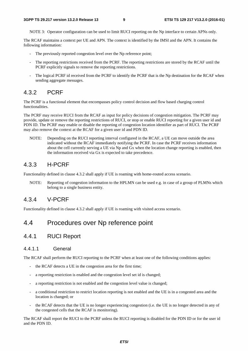
4.2 Np reference model The relationships between the involved functional entities are depicted in figure 4.2.1. The overall PCC architecture is depicted in clause 3a of 3GPP TS 29.213 [3] .
PCRF
Np
RCAF
Figure 4.2.1: Np reference model
NOTE: For the home-routed access scenario, the RCAF interacts with the H-PCRF. For the visited access scenario, the RCAF interacts with the V-PCRF.
Figure 4.2.2: Void
Figure 4.2.3: Void
4.3 Functional elements
4.3.1 RCAF
The RCAF is a functional element which reports RAN User Plane Congestion Information (RUCI) via the Np interface to the PCRF to enable the PCRF to take the RAN user plane congestion status into account for policy decisions. RUCI includes the following information:
- The user id (e.g. IMSI) identifying the UE impacted by congestion;
- PDN ID for which congestion information is reported;
- Congestion level information (either congestion level value or congestion level set id) of the UE impacted by congestion;
- eNodeB identifier, ECGI or SAI identifying the eNodeB, E-UTRAN cell or Service Area respectively, serving the UE if a conditional restriction to restrict location reporting is not enabled.
NOTE 1: In case of E-UTRAN, whether the eNodeB identifier or the ECGI are included in the RUCI is up to operator configuration in the RCAF.
The RCAF sends the RUCI to the PCRFs serving the UEs' PDN connections as follows:
- For a PDN connection in a non-roaming scenario the RCAF reports the RUCI to the PCRF;
- For a PDN connection in a local breakout scenario, based on operator configuration, the RCAF reports the RUCI to the V-PCRF;
- For a PDN connection in a home routed scenario, based on the roaming agreement with the HPLMN and operator configuration, the RCAF reports the RUCI to the H-PCRF
NOTE 2: Reporting of congestion information to the HPLMN may be used e.g. in case of a group of PLMNs which belong to a single business entity.
The RCAF determines whether a given PDN connection is served in a local breakout or a home routed roaming scenario based on the APN operator identifier received as part of the APN information from the MME or the SGSN as documented in 3GPP TS 23.401 [8] and 3GPP TS 23.060 [9], respectively.
ETSI
ETSI TS 129 217 V13.2.0 (2016-01)93GPP TS 29.217 version 13.2.0 Release 13
NOTE 3: Operator configuration can be used to limit RUCI reporting on the Np interface to certain APNs only.
The RCAF maintains a context per UE and APN. The context is identified by the IMSI and the APN. It contains the following information:
- The previously reported congestion level over the Np reference point;
- The reporting restrictions received from the PCRF. The reporting restrictions are stored by the RCAF until the PCRF explicitly signals to remove the reporting restrictions.
- The logical PCRF id received from the PCRF to identify the PCRF that is the Np destination for the RCAF when sending aggregate messages.
4.3.2 PCRF
The PCRF is a functional element that encompasses policy control decision and flow based charging control functionalities.
The PCRF may receive RUCI from the RCAF as input for policy decisions of congestion mitigation. The PCRF may provide, update or remove the reporting restrictions of RUCI, or stop or enable RUCI reporting for a given user id and PDN ID. The PCRF may enable or disable the reporting of congestion location identifier as part of RUCI. The PCRF may also remove the context at the RCAF for a given user id and PDN ID.
NOTE: Depending on the RUCI reporting interval configured in the RCAF, a UE can move outside the area indicated without the RCAF immediately notifying the PCRF. In case the PCRF receives information about the cell currently serving a UE via Np and Gx when the location change reporting is enabled, then the information received via Gx is expected to take precedence.
4.3.3 H-PCRF
Functionality defined in clause 4.3.2 shall apply if UE is roaming with home-routed access scenario.
NOTE: Reporting of congestion information to the HPLMN can be used e.g. in case of a group of PLMNs which belong to a single business entity.
4.3.4 V-PCRF
Functionality defined in clause 4.3.2 shall apply if UE is roaming with visited access scenario.
4.4 Procedures over Np reference point
4.4.1 RUCI Report
4.4.1.1 General
The RCAF shall perform the RUCI reporting to the PCRF when at least one of the following conditions applies:
- the RCAF detects a UE in the congestion area for the first time;
- a reporting restriction is enabled and the congestion level set id is changed;
- a reporting restriction is not enabled and the congestion level value is changed;
- a conditional restriction to restrict location reporting is not enabled and the UE is in a congested area and the location is changed; or
- the RCAF detects that the UE is no longer experiencing congestion (i.e. the UE is no longer detected in any of the congested cells that the RCAF is monitoring).
The RCAF shall report the RUCI to the PCRF unless the RUCI reporting is disabled for the PDN ID or for the user id and the PDN ID.
ETSI
ETSI TS 129 217 V13.2.0 (2016-01)103GPP TS 29.217 version 13.2.0 Release 13
Two types of RUCI reports may be used on Np for transfer of congestion information from RCAF to PCRF: Non-aggregated RUCI report and Aggregated RUCI report. If the RCAF does not know the destination PCRF for the user id and PDN ID, the Non-aggregated RUCI report shall be used; otherwise the RCAF may use either the Non-aggregate RUCI report or Aggregated RUCI report for the user id and PDN ID.
4.4.1.2 Non-aggregated RUCI report
For a Non-aggregated RUCI report, the RCAF shall send an NRR command to the PCRF by including the user id within the Subscription-Id AVP, PDN ID within the Called-Station-Id AVP and a congestion level set id within the Congestion-Level-Set-Id AVP if the reporting restriction was provided earlier or a congestion level value within the Congestion-Level-Value AVP if the reporting restriction was not provided earlier at the command level. The RCAF may also provide congestion location identifier of the UE within the Congestion-Location-Id AVP in the NRR command. The RCAF shall also include the RCAF Identity within the RCAF-Id AVP in every NRR command for a specific user id and PDN ID.
Once the PCRF receives the NRR command, the PCRF shall store the related info and respond with an NRA command including the PCRF id within the PCRF-Address AVP. The PCRF may use the RUCI received from the RCAF as input for policy decisions. When the RCAF receives the NRA command, the RCAF may store the PCRF id in the UE context for this specific user id together with PDN ID for further aggregated RUCI report.
If the ReportRestriction feature is supported by both the RCAF and the PCRF, the PCRF may provide reporting restrictions in the NRA command according to clause 4.4.2.
4.4.1.3 Aggregated RUCI report
For an Aggregated RUCI report, the RCAF shall aggregate the RUCIs of different user ids and PDN IDs that have same destination PCRF. The RCAF shall send an ARR command to the destination PCRF by including the PCRF id within the Destination-Host AVP, one or more Aggregated-RUCI-Report AVP with a congestion level set id within the Congestion-Level-Set-Id AVP if the reporting restriction was provided earlier or a congestion level value within the Congestion-Level-Value AVP if the reporting restriction was not provided earlier, the PDN ID within the Called-Station-ID AVP and a list of aggregated congestion information within the Aggregated-Congestion-Info AVP.
NOTE 1: Each instance of Aggregated-RUCI-Report AVP aggregates the user id list of the subscribers that share the same level of congestion or share the same congestion level set id.
NOTE 2: When the RCAF assembles a Diameter ARR command, if the message length of ARR command has exceeded the maximum length of Diameter message which can be configurable, the RCAF can divide the original ARR command into multiple aggregated RUCI messages for the delivery over Np reference point.
Once the PCRF receives the ARR command, the PCRF shall store the related info and respond with an ARA command. The PCRF may use the RUCI received from the RCAF as input for policy decisions.
4.4.2 Reporting Restriction Provisioning
If the ReportRestriction feature is supported by both the RCAF and the PCRF, the PCRF may provide the reporting restrictions for a specific user id and PDN ID in the initial NRA command. The PCRF may also provide, modify or disable restrictions for RUCI reporting or stop or enable RUCI reporting for the specific user id and PDN ID at any later time. The PCRF may also use this procedure to enable or disable the reporting of congestion location identifier as part of RUCI.
In order to initially provide the reporting restrictions, the PCRF shall send a Modify-Uecontext-Request (MUR) command including the targeted Subscription-Id AVP indicating the user id, the Called-Station-Id AVP indicating the targeted PDN ID and one or more Congestion-Level-Definition AVP(s) including the defined congestion level set within the Congestion-Level-Set-Id AVP and corresponding congestion level(s) within the Congestion-Level-Range AVP or reply with an NRA command including one or more Congestion-Level-Definition AVP(s) including the defined congestion level set within the Congestion-Level-Set-Id AVP and corresponding congestion level(s) within the Congestion-Level-Range AVP . The PCRF may also include the Reporting-Restriction AVP and Conditional-Restriction AVP to indicate when conditional reporting restrictions apply.
The PCRF may modify already provided reporting restrictions. To do so the PCRF shall provide the complete list of congestion level sets and corresponding congestion levels to be used in the same manner as when initially providing
ETSI
ETSI TS 129 217 V13.2.0 (2016-01)113GPP TS 29.217 version 13.2.0 Release 13
reporting restrictions. This complete list shall replace any previously provided list. The absence of Reporting-Restriction AVP and Conditional-Restriction AVP indicates that previous state of reporting restrictions remains valid.
If reporting restrictions has been provided for a specific user id and PDN ID, the PCRF may remove the reporting restrictions by, in the MUR command, including the Reporting-Restriction AVP set to 0 (No reporting restriction), together with Subscription-Id AVP indicating the user id and the Called-Station-Id AVP indicating the targeted PDN ID or reply with an NRA command including the Reporting-Restriction AVP set to 0 (No reporting restriction).
The PCRF may disable RUCI reporting by, in the MUR command, including the RUCI-Action AVP set to 0 (Disable RUCI Reporting), together with Subscription-Id AVP indicating the user id and the Called-Station-Id AVP indicating the targeted PDN ID or reply with an NRA command including the RUCI-Action AVP set to 0 (Disable RUCI Reporting).
To enable RUCI Reporting if previously disabled, the PCRF in the MUR command shall include the RUCI-Action AVP set to1 (Enable RUCI Reporting), together with Subscription-Id AVP indicating the user id and the Called-Station-Id AVP indicating the targeted PDN ID or reply with an NRA command including the RUCI-Action AVP set to 1 (Enable RUCI Reporting).
If reporting restrictions also applies, the PCRF shall include one or more Congestion-Level-Definition AVP(s) including the defined congestion level set with the Congestion-Level-Set-Id AVP and corresponding congestion level(s) within the Congestion-Level-Range AVP, within the same command.
To provision the reporting restriction which disables the reporting of congestion location identifier of the UE as part of RUCI, the PCRF shall include Reporting-Restriction AVP set to 1 (Conditional reporting restriction) and Conditional-Restriction AVP with the bit 0 be set. To enable a previously disabled reporting of the congestion location identifier of the UE as part of RUCI, the PCRF shall include Reporting-Restriction AVP set to 2 (Unconditional reporting restriction).
The PCRF shall include the value of the RCAF-Id AVP received in the NRR command for the specific user id and PDN ID in the Destination-Host AVP of the MUR command.
The RCAF acknowledges the received MUR command by sending a Modify-Uecontext-Answer (MUA) command in all cases above.
4.4.3 UE mobility between RCAFs
If RUCI reporting is used for a specific user id and PDN ID and the PCRF receives a new non-aggregated RUCI report for the same user id and PDN ID but with a different RCAF id included in the RCAF-Id AVP, the PCRF shall update the related information and respond with an NRA command according to clause 4.4.1.1.
The PCRF shall also initiate a removal of the UE context to the old RCAF according to clause 4.4.4.
4.4.4 Removal of UE context
This procedure is initiated when the PCRF needs to remove a UE context from the RCAF, e.g. at UE mobility between RCAFs.
If the PCRF due to an event determines that a UE context needs to be removed from the RCAF, the PCRF shall send an MUR command to the targeted RCAF to explicitly release the context related to the user id and PDN ID by including the Subscription-Id AVP indicating the user id, the Called-Station-Id AVP indicating the PDN ID, the Destination-Host AVP indicating the targeted RCAF id and the RUCI-Action AVP set to 2 (Release Context).
The RCAF when receiving the MUR command from the PCRF shall release the context related to the user id and PDN ID. If this is the last PDN ID stored for this user id the RCAF shall release the complete context.
The RCAF shall acknowledge the received MUR command by sending an MUA command.
4.4.5 Race condition handling
If the RCAF receives an MUR command to remove a context for a specific user id and PDN ID, the request shall be handled immediately, regardless of whether there are any ongoing RUCI report transactions for that user id and PDN ID.
ETSI
ETSI TS 129 217 V13.2.0 (2016-01)123GPP TS 29.217 version 13.2.0 Release 13
If the PCRF receives an NRR command for a specific user id and PDN ID, and if there is an ongoing MUR command to remove the context for that user id and PDN ID, the PCRF shall reject the incoming request with a Diameter experimental result code of DIAMETER_PENDING_TRANSACTION.
If the PCRF receives an ARR command for specific user id and PDN ID combinations for which there is at least one ongoing MUR command to remove the context, the PCRF shall accept the request and only update the context(s) that are not in the process of being removed.
5 Np protocol
5.1 Protocol support The Np application is defined as a vendor specific Diameter application, where the vendor is 3GPP and the Application-ID for the Np Application in the present release is xxxx. The vendor identifier assigned by IANA to 3GPP (http://www.iana.org/assignments/enterprise-numbers) is 10415.
NOTE: A route entry can have a different destination based on the application identification AVP of the message. Therefore, Diameter agents (relay, proxy, redirection, translation agents) must be configured appropriately to identify the 3GPP Np application within the Auth-Application-Id AVP in order to create suitable routeing tables.
With regard to the Diameter protocol defined over the Np interface, the PCRF acts as a Diameter server, in the sense that it is the network element that handles the RUCI reporting for a particular realm. The RCAF acts as the Diameter client, in the sense that it is the network element reporting the RUCI.
5.2 Initialization, maintenance and termination of connection and session
The initialization and maintenance of the connection between the RCAF and PCRF are defined by the underlying protocol. Establishment and maintenance of connections between Diameter nodes are described in IETF RFC 3588 [7].
After establishing the transport connection, the RCAF and the PCRF shall advertise the support of the Np specific Application by including the value of the application identifier in the Auth-Application-Id AVP and the value of the 3GPP (10415) in the Vendor-Id AVP of the Vendor-Specific-Application-Id AVP contained in the Capabilities-Exchange-Request and Capabilities-Exchange-Answer commands. The Capabilities-Exchange-Request and Capabilities-Exchange-Answer commands are specified in the Diameter Base Protocol (IETF RFC 3588 [7]).
The Np Diameter session shall be terminated after each request and answer pair interaction.
In order to indicate that the session state is not to be maintained, the Diameter client and server shall include the Auth-Session-State AVP with the value set to NO_STATE_MAINTAINED (1), in the request and in the answer messages (see IETF RFC 3588 [7]).
5.3 Np specific AVPs
5.3.1 General
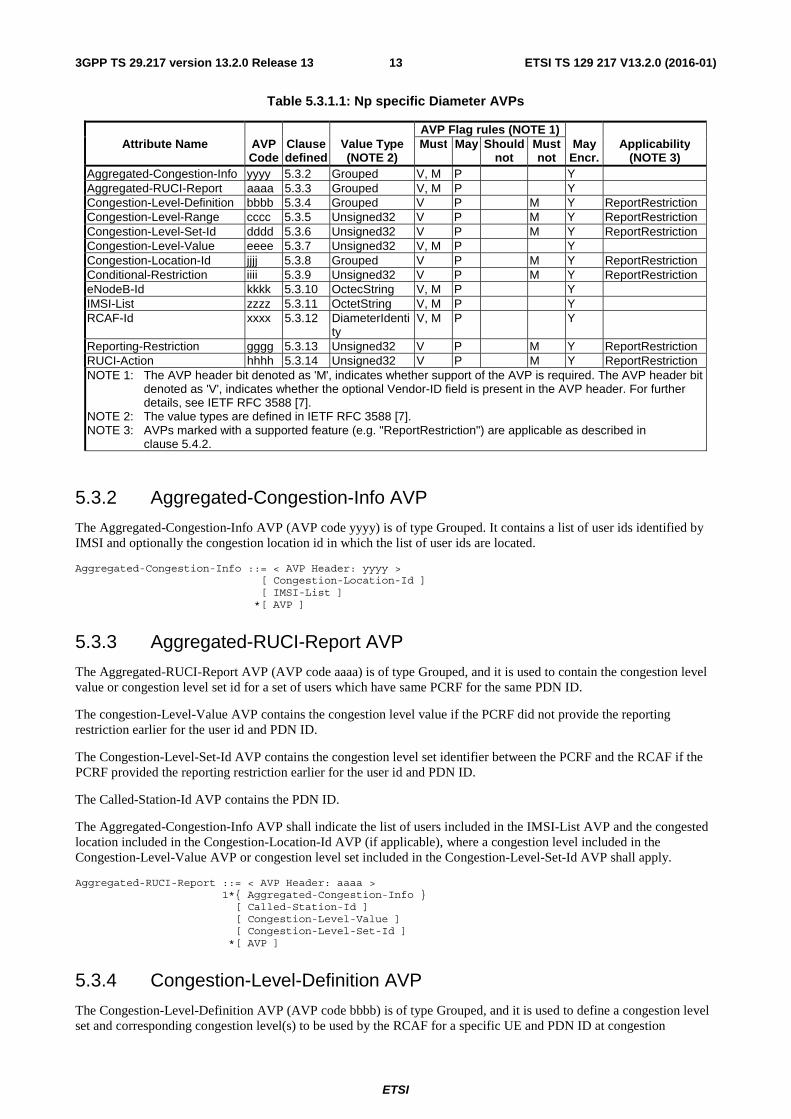
Table 5.3.1.1 describes the Diameter AVPs defined for the Np reference point, their AVP Code values, types, possible flag values, whether or not the AVP may be encrypted and which supported features the AVP is applicable to. The Vendor-Id header of all AVPs defined in the present document shall be set to 3GPP (10415).
ETSI
ETSI TS 129 217 V13.2.0 (2016-01)133GPP TS 29.217 version 13.2.0 Release 13
Table 5.3.1.1: Np specific Diameter AVPs
AVP Flag rules (NOTE 1) Attribute Name AVP
Code Clause defined
Value Type (NOTE 2)
Must May Should not
Must not
May Encr.
Applicability (NOTE 3)
Aggregated-Congestion-Info yyyy 5.3.2 Grouped V, M P Y Aggregated-RUCI-Report aaaa 5.3.3 Grouped V, M P Y Congestion-Level-Definition bbbb 5.3.4 Grouped V P M Y ReportRestriction Congestion-Level-Range cccc 5.3.5 Unsigned32 V P M Y ReportRestriction Congestion-Level-Set-Id dddd 5.3.6 Unsigned32 V P M Y ReportRestriction Congestion-Level-Value eeee 5.3.7 Unsigned32 V, M P Y Congestion-Location-Id jjjj 5.3.8 Grouped V P M Y ReportRestriction Conditional-Restriction iiii 5.3.9 Unsigned32 V P M Y ReportRestriction eNodeB-Id kkkk 5.3.10 OctecString V, M P Y IMSI-List zzzz 5.3.11 OctetString V, M P Y RCAF-Id xxxx 5.3.12 DiameterIdenti
ty V, M P Y
Reporting-Restriction gggg 5.3.13 Unsigned32 V P M Y ReportRestriction RUCI-Action hhhh 5.3.14 Unsigned32 V P M Y ReportRestriction NOTE 1: The AVP header bit denoted as 'M', indicates whether support of the AVP is required. The AVP header bit
denoted as 'V', indicates whether the optional Vendor-ID field is present in the AVP header. For further details, see IETF RFC 3588 [7].
NOTE 2: The value types are defined in IETF RFC 3588 [7]. NOTE 3: AVPs marked with a supported feature (e.g. "ReportRestriction") are applicable as described in
clause 5.4.2.
5.3.2 Aggregated-Congestion-Info AVP
The Aggregated-Congestion-Info AVP (AVP code yyyy) is of type Grouped. It contains a list of user ids identified by IMSI and optionally the congestion location id in which the list of user ids are located.
Aggregated-Congestion-Info ::= < AVP Header: yyyy > [ Congestion-Location-Id ] [ IMSI-List ] *[ AVP ]
5.3.3 Aggregated-RUCI-Report AVP
The Aggregated-RUCI-Report AVP (AVP code aaaa) is of type Grouped, and it is used to contain the congestion level value or congestion level set id for a set of users which have same PCRF for the same PDN ID.
The congestion-Level-Value AVP contains the congestion level value if the PCRF did not provide the reporting restriction earlier for the user id and PDN ID.
The Congestion-Level-Set-Id AVP contains the congestion level set identifier between the PCRF and the RCAF if the PCRF provided the reporting restriction earlier for the user id and PDN ID.
The Called-Station-Id AVP contains the PDN ID.
The Aggregated-Congestion-Info AVP shall indicate the list of users included in the IMSI-List AVP and the congested location included in the Congestion-Location-Id AVP (if applicable), where a congestion level included in the Congestion-Level-Value AVP or congestion level set included in the Congestion-Level-Set-Id AVP shall apply.
Aggregated-RUCI-Report ::= < AVP Header: aaaa > 1*{ Aggregated-Congestion-Info } [ Called-Station-Id ] [ Congestion-Level-Value ] [ Congestion-Level-Set-Id ] *[ AVP ]
5.3.4 Congestion-Level-Definition AVP
The Congestion-Level-Definition AVP (AVP code bbbb) is of type Grouped, and it is used to define a congestion level set and corresponding congestion level(s) to be used by the RCAF for a specific UE and PDN ID at congestion
ETSI
ETSI TS 129 217 V13.2.0 (2016-01)143GPP TS 29.217 version 13.2.0 Release 13
reporting. When this AVP is present in the MUR command reporting restrictions apply, when this AVP is absent there are no reporting restriction for the specific UE and PDN ID.
Congestion-Level-Definition ::= < AVP Header: bbbb > { Congestion-Level-Set-Id } { Congestion-Level-Range } *[ AVP ]
5.3.5 Congestion-Level-Range AVP
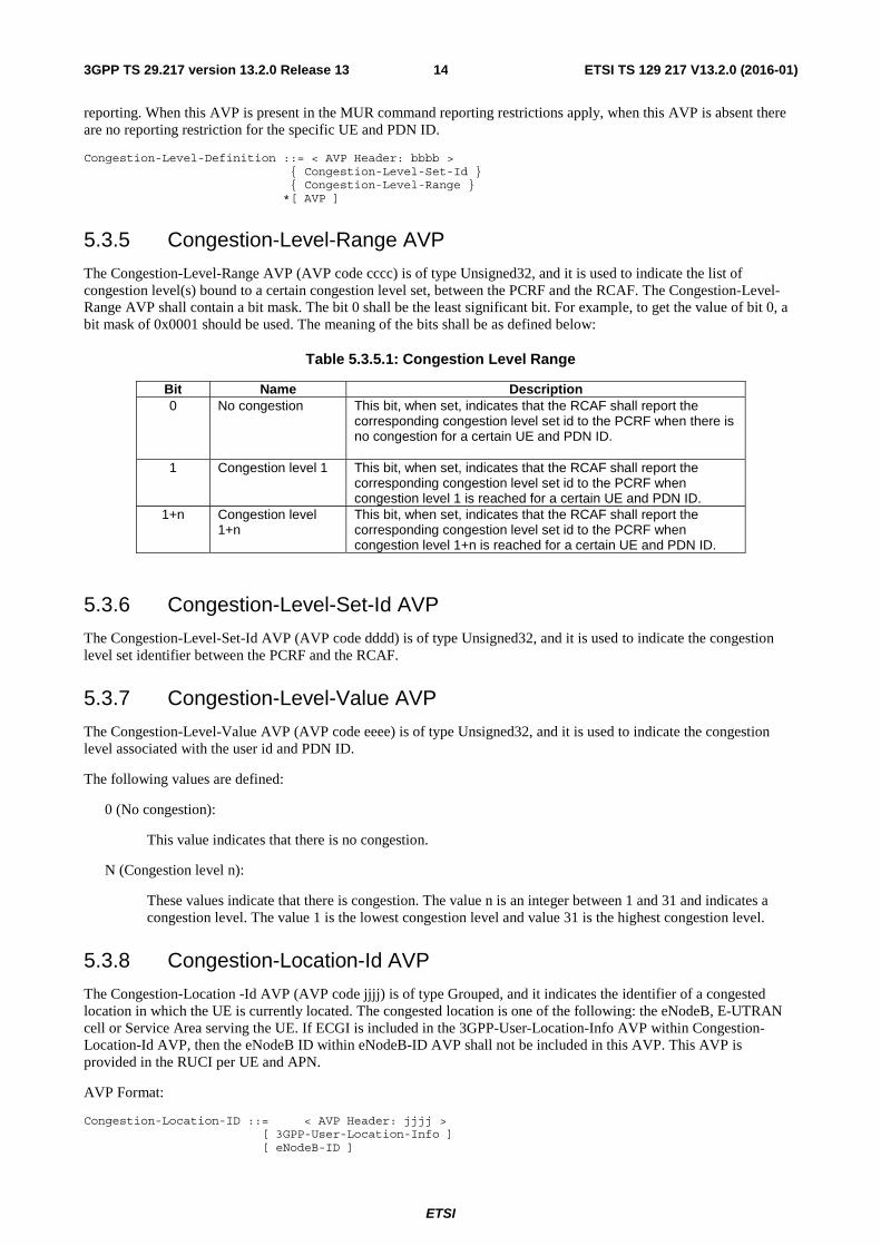
The Congestion-Level-Range AVP (AVP code cccc) is of type Unsigned32, and it is used to indicate the list of congestion level(s) bound to a certain congestion level set, between the PCRF and the RCAF. The Congestion-Level-Range AVP shall contain a bit mask. The bit 0 shall be the least significant bit. For example, to get the value of bit 0, a bit mask of 0x0001 should be used. The meaning of the bits shall be as defined below:
Table 5.3.5.1: Congestion Level Range
Bit Name Description 0 No congestion This bit, when set, indicates that the RCAF shall report the
corresponding congestion level set id to the PCRF when there is no congestion for a certain UE and PDN ID.
1 Congestion level 1 This bit, when set, indicates that the RCAF shall report the corresponding congestion level set id to the PCRF when congestion level 1 is reached for a certain UE and PDN ID.
1+n Congestion level 1+n
This bit, when set, indicates that the RCAF shall report the corresponding congestion level set id to the PCRF when congestion level 1+n is reached for a certain UE and PDN ID.
5.3.6 Congestion-Level-Set-Id AVP
The Congestion-Level-Set-Id AVP (AVP code dddd) is of type Unsigned32, and it is used to indicate the congestion level set identifier between the PCRF and the RCAF.
5.3.7 Congestion-Level-Value AVP
The Congestion-Level-Value AVP (AVP code eeee) is of type Unsigned32, and it is used to indicate the congestion level associated with the user id and PDN ID.
The following values are defined:
0 (No congestion):
This value indicates that there is no congestion.
N (Congestion level n):
These values indicate that there is congestion. The value n is an integer between 1 and 31 and indicates a congestion level. The value 1 is the lowest congestion level and value 31 is the highest congestion level.
5.3.8 Congestion-Location-Id AVP
The Congestion-Location -Id AVP (AVP code jjjj) is of type Grouped, and it indicates the identifier of a congested location in which the UE is currently located. The congested location is one of the following: the eNodeB, E-UTRAN cell or Service Area serving the UE. If ECGI is included in the 3GPP-User-Location-Info AVP within Congestion-Location-Id AVP, then the eNodeB ID within eNodeB-ID AVP shall not be included in this AVP. This AVP is provided in the RUCI per UE and APN.
AVP Format:
Congestion-Location-ID ::= < AVP Header: jjjj > [ 3GPP-User-Location-Info ] [ eNodeB-ID ]
ETSI
ETSI TS 129 217 V13.2.0 (2016-01)153GPP TS 29.217 version 13.2.0 Release 13
*[ AVP ]
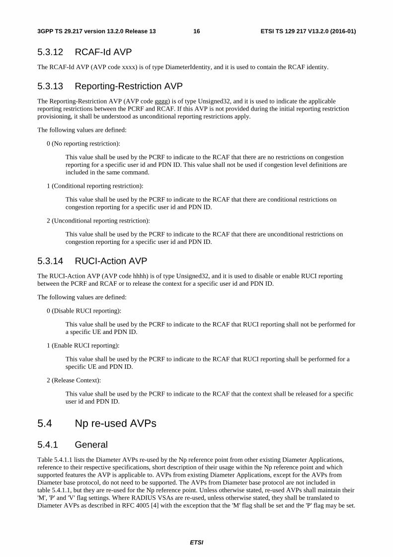
5.3.9 Conditional-Restriction AVP
The Conditional-Restriction AVP (AVP code iiii) is of type Unsigned32 and it shall contain a bit mask, and indicates what conditional reporting restrictions apply. Conditional reporting restrictions shall apply when this AVP is provided. The bit 0 shall be the least significant bit. For example, to get the value of bit 0, a bit mask of 0x0001 should be used. The meaning of the bits shall be as defined below:
Table 5.3.9.1: Conditional-Restriction over Np
Bit Name Description 0 UE location info not included
in RUCI This bit, when set, indicates that the location information of the UE shall not be included in RUCI for reporting.
5.3.10 eNodeB-ID AVP
The eNodeB-ID AVP (AVP code kkkk) is of type OctetString, and indicates the eNodeB in which the UE is currently located. The AVP shall be coded as in clause 8.51 of 3GPP TS 29.274 [12].
5.3.11 IMSI-List AVP
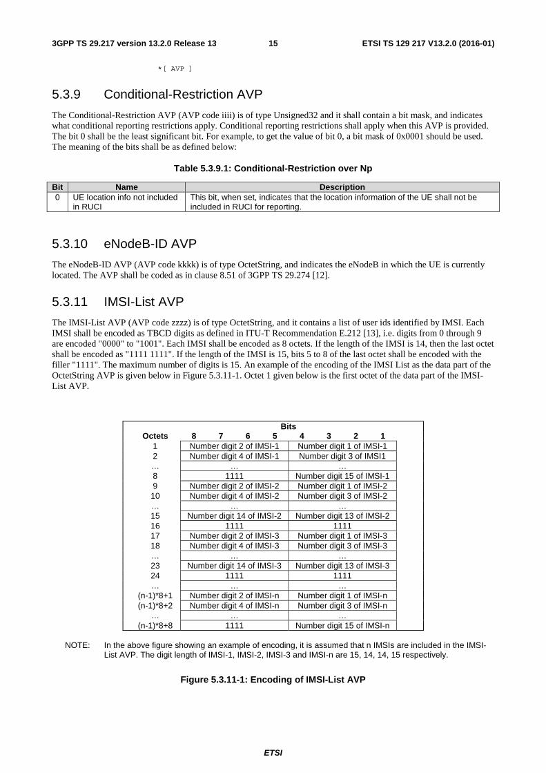
The IMSI-List AVP (AVP code zzzz) is of type OctetString, and it contains a list of user ids identified by IMSI. Each IMSI shall be encoded as TBCD digits as defined in ITU-T Recommendation E.212 [13], i.e. digits from 0 through 9 are encoded "0000" to "1001". Each IMSI shall be encoded as 8 octets. If the length of the IMSI is 14, then the last octet shall be encoded as "1111 1111". If the length of the IMSI is 15, bits 5 to 8 of the last octet shall be encoded with the filler "1111". The maximum number of digits is 15. An example of the encoding of the IMSI List as the data part of the OctetString AVP is given below in Figure 5.3.11-1. Octet 1 given below is the first octet of the data part of the IMSI-List AVP.
Bits Octets 8 7 6 5 4 3 2 1 1 Number digit 2 of IMSI-1 Number digit 1 of IMSI-1 2 Number digit 4 of IMSI-1 Number digit 3 of IMSI1 … … … 8 1111 Number digit 15 of IMSI-1 9 Number digit 2 of IMSI-2 Number digit 1 of IMSI-2 10 Number digit 4 of IMSI-2 Number digit 3 of IMSI-2 … … … 15 Number digit 14 of IMSI-2 Number digit 13 of IMSI-2 16 1111 1111 17 Number digit 2 of IMSI-3 Number digit 1 of IMSI-3 18 Number digit 4 of IMSI-3 Number digit 3 of IMSI-3 … … … 23 Number digit 14 of IMSI-3 Number digit 13 of IMSI-3 24 1111 1111 … … … (n-1)*8+1 Number digit 2 of IMSI-n Number digit 1 of IMSI-n (n-1)*8+2 Number digit 4 of IMSI-n Number digit 3 of IMSI-n … … … (n-1)*8+8 1111 Number digit 15 of IMSI-n
NOTE: In the above figure showing an example of encoding, it is assumed that n IMSIs are included in the IMSI-
List AVP. The digit length of IMSI-1, IMSI-2, IMSI-3 and IMSI-n are 15, 14, 14, 15 respectively.
Figure 5.3.11-1: Encoding of IMSI-List AVP
ETSI
ETSI TS 129 217 V13.2.0 (2016-01)163GPP TS 29.217 version 13.2.0 Release 13
5.3.12 RCAF-Id AVP
The RCAF-Id AVP (AVP code xxxx) is of type DiameterIdentity, and it is used to contain the RCAF identity.
5.3.13 Reporting-Restriction AVP
The Reporting-Restriction AVP (AVP code gggg) is of type Unsigned32, and it is used to indicate the applicable reporting restrictions between the PCRF and RCAF. If this AVP is not provided during the initial reporting restriction provisioning, it shall be understood as unconditional reporting restrictions apply.
The following values are defined:
0 (No reporting restriction):
This value shall be used by the PCRF to indicate to the RCAF that there are no restrictions on congestion reporting for a specific user id and PDN ID. This value shall not be used if congestion level definitions are included in the same command.
1 (Conditional reporting restriction):
This value shall be used by the PCRF to indicate to the RCAF that there are conditional restrictions on congestion reporting for a specific user id and PDN ID.
2 (Unconditional reporting restriction):
This value shall be used by the PCRF to indicate to the RCAF that there are unconditional restrictions on congestion reporting for a specific user id and PDN ID.
5.3.14 RUCI-Action AVP
The RUCI-Action AVP (AVP code hhhh) is of type Unsigned32, and it is used to disable or enable RUCI reporting between the PCRF and RCAF or to release the context for a specific user id and PDN ID.
The following values are defined:
0 (Disable RUCI reporting):
This value shall be used by the PCRF to indicate to the RCAF that RUCI reporting shall not be performed for a specific UE and PDN ID.
1 (Enable RUCI reporting):
This value shall be used by the PCRF to indicate to the RCAF that RUCI reporting shall be performed for a specific UE and PDN ID.
2 (Release Context):
This value shall be used by the PCRF to indicate to the RCAF that the context shall be released for a specific user id and PDN ID.
5.4 Np re-used AVPs
5.4.1 General
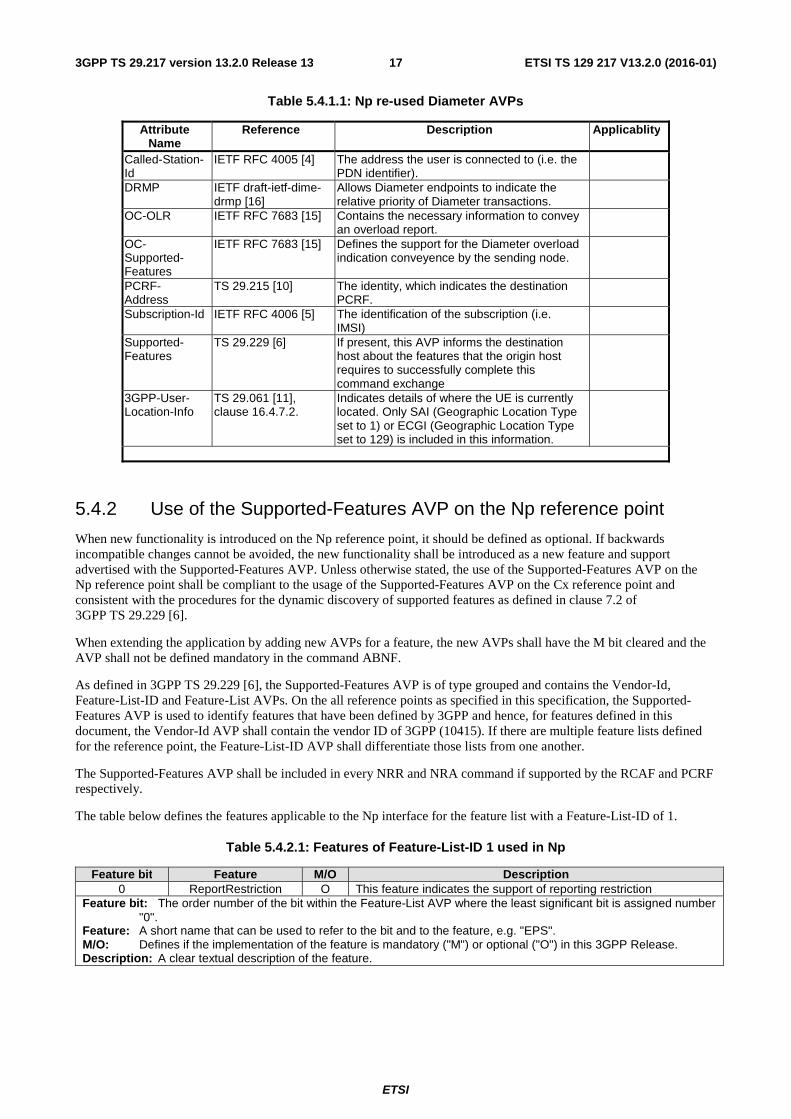
Table 5.4.1.1 lists the Diameter AVPs re-used by the Np reference point from other existing Diameter Applications, reference to their respective specifications, short description of their usage within the Np reference point and which supported features the AVP is applicable to. AVPs from existing Diameter Applications, except for the AVPs from Diameter base protocol, do not need to be supported. The AVPs from Diameter base protocol are not included in table 5.4.1.1, but they are re-used for the Np reference point. Unless otherwise stated, re-used AVPs shall maintain their 'M', 'P' and 'V' flag settings. Where RADIUS VSAs are re-used, unless otherwise stated, they shall be translated to Diameter AVPs as described in RFC 4005 [4] with the exception that the 'M' flag shall be set and the 'P' flag may be set.
ETSI
ETSI TS 129 217 V13.2.0 (2016-01)173GPP TS 29.217 version 13.2.0 Release 13
Table 5.4.1.1: Np re-used Diameter AVPs
Attribute Name
Reference Description Applicablity
Called-Station-Id
IETF RFC 4005 [4] The address the user is connected to (i.e. the PDN identifier).
DRMP IETF draft-ietf-dime-drmp [16]
Allows Diameter endpoints to indicate the relative priority of Diameter transactions.
OC-OLR IETF RFC 7683 [15] Contains the necessary information to convey an overload report.
OC-Supported-Features
IETF RFC 7683 [15] Defines the support for the Diameter overload indication conveyence by the sending node.
PCRF-Address
TS 29.215 [10] The identity, which indicates the destination PCRF.
Subscription-Id IETF RFC 4006 [5] The identification of the subscription (i.e. IMSI)
Supported-Features
TS 29.229 [6] If present, this AVP informs the destination host about the features that the origin host requires to successfully complete this command exchange
3GPP-User-Location-Info
TS 29.061 [11], clause 16.4.7.2.
Indicates details of where the UE is currently located. Only SAI (Geographic Location Type set to 1) or ECGI (Geographic Location Type set to 129) is included in this information.
5.4.2 Use of the Supported-Features AVP on the Np reference point
When new functionality is introduced on the Np reference point, it should be defined as optional. If backwards incompatible changes cannot be avoided, the new functionality shall be introduced as a new feature and support advertised with the Supported-Features AVP. Unless otherwise stated, the use of the Supported-Features AVP on the Np reference point shall be compliant to the usage of the Supported-Features AVP on the Cx reference point and consistent with the procedures for the dynamic discovery of supported features as defined in clause 7.2 of 3GPP TS 29.229 [6].
When extending the application by adding new AVPs for a feature, the new AVPs shall have the M bit cleared and the AVP shall not be defined mandatory in the command ABNF.
As defined in 3GPP TS 29.229 [6], the Supported-Features AVP is of type grouped and contains the Vendor-Id, Feature-List-ID and Feature-List AVPs. On the all reference points as specified in this specification, the Supported-Features AVP is used to identify features that have been defined by 3GPP and hence, for features defined in this document, the Vendor-Id AVP shall contain the vendor ID of 3GPP (10415). If there are multiple feature lists defined for the reference point, the Feature-List-ID AVP shall differentiate those lists from one another.
The Supported-Features AVP shall be included in every NRR and NRA command if supported by the RCAF and PCRF respectively.
The table below defines the features applicable to the Np interface for the feature list with a Feature-List-ID of 1.
Table 5.4.2.1: Features of Feature-List-ID 1 used in Np
Feature bit Feature M/O Description 0 ReportRestriction O This feature indicates the support of reporting restriction
Feature bit: The order number of the bit within the Feature-List AVP where the least significant bit is assigned number "0".
Feature: A short name that can be used to refer to the bit and to the feature, e.g. "EPS". M/O: Defines if the implementation of the feature is mandatory ("M") or optional ("O") in this 3GPP Release. Description: A clear textual description of the feature.
ETSI
ETSI TS 129 217 V13.2.0 (2016-01)183GPP TS 29.217 version 13.2.0 Release 13
5.5 Np specific Experimental-Result-Code AVP values
5.5.1 General
This clause defines result code values that shall be supported by Diameter implementations that conform to this specification.
5.5.2 Success
Result Codes that fall into the Success category are used to inform a peer that a request has been successfully completed. The Result-Code AVP values defined in Diameter BASE IETF RFC 3588 [7] are applied.
5.5.3 Permanent Failures
Errors that fall into the Failures category shall be used to inform the peer that the request has failed. The Result-Code AVP values defined in Diameter Base Protocol IETF RFC 3588 [7] are applied. As an addition the following Result-Code AVP value defined in IETF RFC 4006 [5] is applicable:
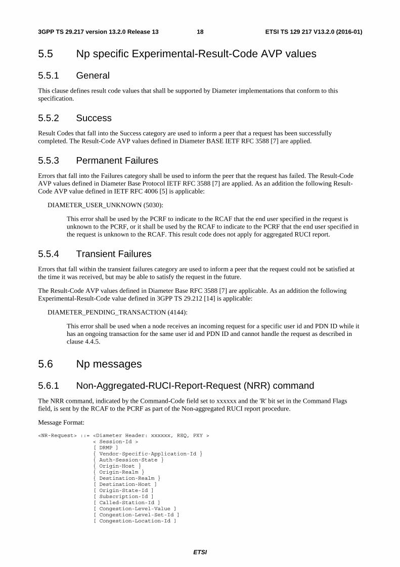
DIAMETER_USER_UNKNOWN (5030):
This error shall be used by the PCRF to indicate to the RCAF that the end user specified in the request is unknown to the PCRF, or it shall be used by the RCAF to indicate to the PCRF that the end user specified in the request is unknown to the RCAF. This result code does not apply for aggregated RUCI report.
5.5.4 Transient Failures
Errors that fall within the transient failures category are used to inform a peer that the request could not be satisfied at the time it was received, but may be able to satisfy the request in the future.
The Result-Code AVP values defined in Diameter Base RFC 3588 [7] are applicable. As an addition the following Experimental-Result-Code value defined in 3GPP TS 29.212 [14] is applicable:
DIAMETER_PENDING_TRANSACTION (4144):
This error shall be used when a node receives an incoming request for a specific user id and PDN ID while it has an ongoing transaction for the same user id and PDN ID and cannot handle the request as described in clause 4.4.5.
5.6 Np messages
5.6.1 Non-Aggregated-RUCI-Report-Request (NRR) command
The NRR command, indicated by the Command-Code field set to xxxxxx and the 'R' bit set in the Command Flags field, is sent by the RCAF to the PCRF as part of the Non-aggregated RUCI report procedure.
Message Format:
<NR-Request> ::= <Diameter Header: xxxxxx, REQ, PXY > < Session-Id > [ DRMP ] { Vendor-Specific-Application-Id } { Auth-Session-State } { Origin-Host } { Origin-Realm } { Destination-Realm } [ Destination-Host ] [ Origin-State-Id ] [ Subscription-Id ] [ Called-Station-Id ] [ Congestion-Level-Value ] [ Congestion-Level-Set-Id ] [ Congestion-Location-Id ]
ETSI
ETSI TS 129 217 V13.2.0 (2016-01)193GPP TS 29.217 version 13.2.0 Release 13
[ OC-Supported-Features ] [ RCAF-Id ] *[ Proxy-Info ] *[ Route-Record ] *[ Supported-Features ] *[ AVP ]
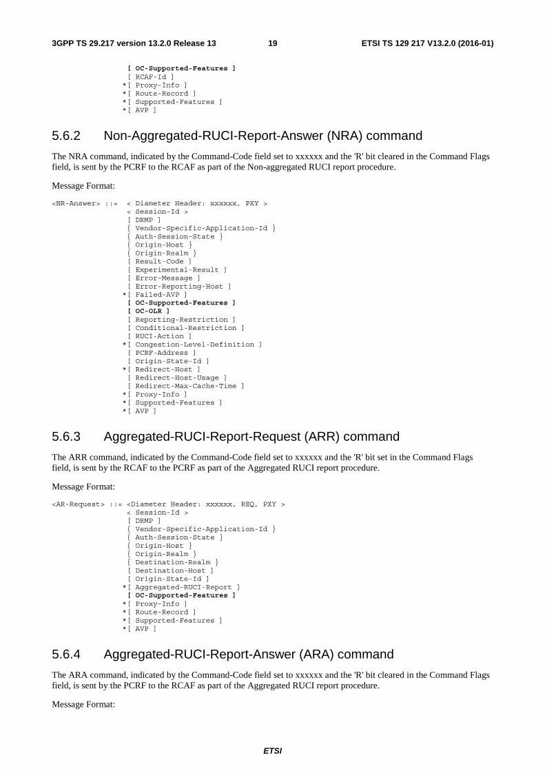
5.6.2 Non-Aggregated-RUCI-Report-Answer (NRA) command
The NRA command, indicated by the Command-Code field set to xxxxxx and the 'R' bit cleared in the Command Flags field, is sent by the PCRF to the RCAF as part of the Non-aggregated RUCI report procedure.
Message Format:
<NR-Answer> ::= < Diameter Header: xxxxxx, PXY > < Session-Id > [ DRMP ] { Vendor-Specific-Application-Id } { Auth-Session-State } { Origin-Host } { Origin-Realm } [ Result-Code ] [ Experimental-Result ] [ Error-Message ] [ Error-Reporting-Host ] *[ Failed-AVP ] [ OC-Supported-Features ] [ OC-OLR ] [ Reporting-Restriction ] [ Conditional-Restriction ] [ RUCI-Action ] *[ Congestion-Level-Definition ] [ PCRF-Address ] [ Origin-State-Id ] *[ Redirect-Host ] [ Redirect-Host-Usage ] [ Redirect-Max-Cache-Time ] *[ Proxy-Info ] *[ Supported-Features ] *[ AVP ]
5.6.3 Aggregated-RUCI-Report-Request (ARR) command
The ARR command, indicated by the Command-Code field set to xxxxxx and the 'R' bit set in the Command Flags field, is sent by the RCAF to the PCRF as part of the Aggregated RUCI report procedure.
Message Format:
<AR-Request> ::= <Diameter Header: xxxxxx, REQ, PXY > < Session-Id > [ DRMP ] { Vendor-Specific-Application-Id } { Auth-Session-State } { Origin-Host } { Origin-Realm } { Destination-Realm } [ Destination-Host ] [ Origin-State-Id ] *[ Aggregated-RUCI-Report ] [ OC-Supported-Features ] *[ Proxy-Info ] *[ Route-Record ] *[ Supported-Features ] *[ AVP ]
5.6.4 Aggregated-RUCI-Report-Answer (ARA) command
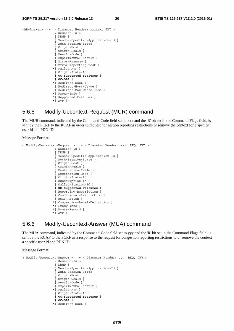
The ARA command, indicated by the Command-Code field set to xxxxxx and the 'R' bit cleared in the Command Flags field, is sent by the PCRF to the RCAF as part of the Aggregated RUCI report procedure.
Message Format:
ETSI
ETSI TS 129 217 V13.2.0 (2016-01)203GPP TS 29.217 version 13.2.0 Release 13
<AR-Answer> ::= < Diameter Header: xxxxxx, PXY > < Session-Id > [ DRMP ] { Vendor-Specific-Application-Id } { Auth-Session-State } { Origin-Host } { Origin-Realm } [ Result-Code ] [ Experimental-Result ] [ Error-Message ] [ Error-Reporting-Host ] *[ Failed-AVP ] [ Origin-State-Id ] [ OC-Supported-Features ] [ OC-OLR ] *[ Redirect-Host ] [ Redirect-Host-Usage ] [ Redirect-Max-Cache-Time ] *[ Proxy-Info ] *[ Supported-Features ] *[ AVP ]
5.6.5 Modify-Uecontext-Request (MUR) command
The MUR command, indicated by the Command-Code field set to xxx and the 'R' bit set in the Command Flags field, is sent by the PCRF to the RCAF in order to request congestion reporting restrictions or remove the context for a specific user id and PDN ID.
Message Format:
< Modify-Uecontext-Request > ::= < Diameter Header: xxx, REQ, PXY > < Session-Id > [ DRMP ] { Vendor-Specific-Application-Id } { Auth-Session-State } { Origin-Host } { Origin-Realm } { Destination-Realm } { Destination-Host } [ Origin-State-Id ] [ Subscription-Id ] [ Called-Station-Id ] [ OC-Supported-Features ] [ Reporting-Restriction ] [ Conditional-Restriction ] [ RUCI-Action ] *[ Congestion-Level-Definition ] *[ Proxy-Info ] *[ Route-Record ] *[ AVP ]
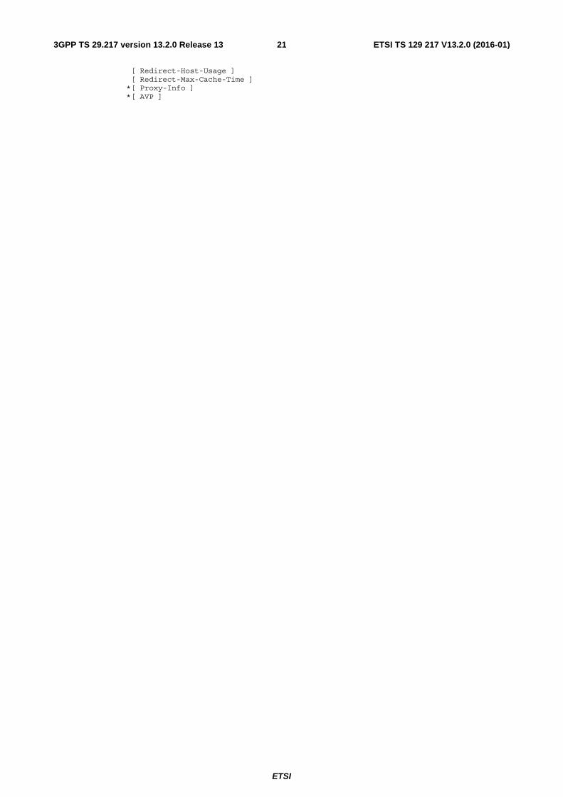
5.6.6 Modify-Uecontext-Answer (MUA) command
The MUA command, indicated by the Command-Code field set to yyy and the 'R' bit set in the Command Flags field, is sent by the RCAF to the PCRF as a response to the request for congestion reporting restrictions to or remove the context a specific user id and PDN ID.
Message Format:
< Modify-Uecontext-Answer > ::= < Diameter Header: yyy, REQ, PXY > < Session-Id > [ DRMP ] { Vendor-Specific-Application-Id } { Auth-Session-State } { Origin-Host } { Origin-Realm } [ Result-Code ] [ Experimental-Result ] *[ Failed-AVP ] [ Origin-State-Id ] [ OC-Supported-Features ] [ OC-OLR ] *[ Redirect-Host ]
ETSI
ETSI TS 129 217 V13.2.0 (2016-01)213GPP TS 29.217 version 13.2.0 Release 13
[ Redirect-Host-Usage ] [ Redirect-Max-Cache-Time ] *[ Proxy-Info ] *[ AVP ]
ETSI
ETSI TS 129 217 V13.2.0 (2016-01)223GPP TS 29.217 version 13.2.0 Release 13
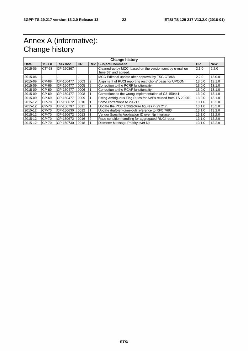
Annex A (informative): Change history
Change history Date TSG # TSG Doc. CR Rev Subject/Comment Old New 2015-06 CT#68 CP-150367 Cleaned-up by MCC, based on the version sent by e-mail on
June 5th and agreed. 2.1.0 2.2.0
2015-06 - - - - MCC Editorial update after approval by TSG CT#68 2.2.0 13.0.0 2015-09 CP-69 CP-150477 0003 2 Alignment of RUCI reporting restrictions' basis for UPCON 13.0.0 13.1.0 2015-09 CP-69 CP-150477 0005 2 Correction to the PCRF functionality 13.0.0 13.1.0 2015-09 CP-69 CP-150477 0006 1 Correction to the RCAF functionality 13.0.0 13.1.0 2015-09 CP-69 CP-150477 0008 1 Corrections to the wrong implementation of C3-150441 13.0.0 13.1.0 2015-09 CP-69 CP-150477 0009 1 Fixing Ambiguous Flag Rules for AVPs reused from TS 29.061 13.0.0 13.1.0 2015-12 CP-70 CP-150672 0010 1 Some corrections to 29.217 13.1.0 13.2.0 2015-12 CP-70 CP-150797 0011 1 Update the PCC architecture figures in 29.217 13.1.0 13.2.0 2015-12 CP-70 CP-150630 0012 1 Update draft-ietf-dime-ovli reference to RFC 7683 13.1.0 13.2.0 2015-12 CP-70 CP-150672 0013 1 Vendor Specific Application ID over Np interface 13.1.0 13.2.0 2015-12 CP-70 CP-150672 0016 2 Race condition handling for aggregated RUCI report 13.1.0 13.2.0 2015-12 CP-70 CP-150730 0018 1 Diameter Message Priority over Np 13.1.0 13.2.0
ETSI
ETSI TS 129 217 V13.2.0 (2016-01)233GPP TS 29.217 version 13.2.0 Release 13
History
Document history
V13.2.0 January 2016 Publication