TS 102 165-1 - V4.2.3 - Telecommunications and Internet - ETSI

ETSI TS 129 010 V4.2.0 (2001-12)
Technical Specification
Digital cellular telecommunications system (Phase 2+) (GSM);Universal Mobile Telecommunications System (UMTS);Information Element Mapping between Mobile Station -
Base Station System (MS - BSS) and Base Station System -Mobile-services Switching Centre (BSS - MSC) Signalling
Procedures and the Mobile Application Part (MAP)(3GPP TS 29.010 version 4.2.0 Release 1999)
GLOBAL SYSTEM FOR MOBILE COMMUNICATIONS
R

ETSI
ETSI TS 129 010 V4.2.0 (2001-12)13GPP TS 29.010 version 4.2.0 Release 1999
Reference RTS/TSGN-0429010Uv4R2
Keywords GSM, UMTS
ETSI
650 Route des Lucioles F-06921 Sophia Antipolis Cedex - FRANCE
Tel.: +33 4 92 94 42 00 Fax: +33 4 93 65 47 16
Siret N° 348 623 562 00017 - NAF 742 C
Association à but non lucratif enregistrée à la Sous-Préfecture de Grasse (06) N° 7803/88
Important notice
Individual copies of the present document can be downloaded from: http://www.etsi.org
The present document may be made available in more than one electronic version or in print. In any case of existing or perceived difference in contents between such versions, the reference version is the Portable Document Format (PDF).
In case of dispute, the reference shall be the printing on ETSI printers of the PDF version kept on a specific network drive within ETSI Secretariat.
Users of the present document should be aware that the document may be subject to revision or change of status. Information on the current status of this and other ETSI documents is available at
http://portal.etsi.org/tb/status/status.asp
If you find errors in the present document, send your comment to: [email protected]
Copyright Notification
No part may be reproduced except as authorized by written permission. The copyright and the foregoing restriction extend to reproduction in all media.
© European Telecommunications Standards Institute 2001.
All rights reserved.

ETSI
ETSI TS 129 010 V4.2.0 (2001-12)23GPP TS 29.010 version 4.2.0 Release 1999
Intellectual Property Rights IPRs essential or potentially essential to the present document may have been declared to ETSI. The information pertaining to these essential IPRs, if any, is publicly available for ETSI members and non-members, and can be found in ETSI SR 000 314: "Intellectual Property Rights (IPRs); Essential, or potentially Essential, IPRs notified to ETSI in respect of ETSI standards", which is available from the ETSI Secretariat. Latest updates are available on the ETSI Web server (http://webapp.etsi.org/IPR/home.asp).
Pursuant to the ETSI IPR Policy, no investigation, including IPR searches, has been carried out by ETSI. No guarantee can be given as to the existence of other IPRs not referenced in ETSI SR 000 314 (or the updates on the ETSI Web server) which are, or may be, or may become, essential to the present document.
Foreword This Technical Specification (TS) has been produced by ETSI 3rd Generation Partnership Project (3GPP).
The present document may refer to technical specifications or reports using their 3GPP identities, UMTS identities or GSM identities. These should be interpreted as being references to the corresponding ETSI deliverables.
The cross reference between GSM, UMTS, 3GPP and ETSI identities can be found under www.etsi.org/key .

ETSI
ETSI TS 129 010 V4.2.0 (2001-12)33GPP TS 29.010 version 4.2.0 Release 1999
Contents
Intellectual Property Rights ................................................................................................................................2
Foreword.............................................................................................................................................................2
Foreword.............................................................................................................................................................5
1 Scope ........................................................................................................................................................6 1.1 References ..........................................................................................................................................................6 1.2 Abbreviations .....................................................................................................................................................7
2 Classification of interworking cases.........................................................................................................7 2.1 Transparent procedures ......................................................................................................................................7 2.2 Non-transparent procedures................................................................................................................................7
3 Interworking in the MSC, Transparent case.............................................................................................8 3.1 General ...............................................................................................................................................................8 3.2 Routeing area updating.....................................................................................................................................10 3.3 Authentication ..................................................................................................................................................11 3.4 Retrieval of the IMSI from the MS ..................................................................................................................12 3.5 Reallocation of TMSI.......................................................................................................................................12 3.6 Retrieval of the IMEI from the MS ..................................................................................................................13 3.7 Tracing subscriber activity ...............................................................................................................................13
4 Non-transparent cases.............................................................................................................................14 4.1 General .............................................................................................................................................................14 4.2 Outgoing call set-up (MS originating call).......................................................................................................14 4.3 Incoming call set-up (MS terminating call)......................................................................................................18 4.4 Cipher mode setting..........................................................................................................................................20 4.5 Inter-MSC Handover ........................................................................................................................................20 4.5.1 Basic Inter-MSC Handover ........................................................................................................................20 4.5.2 Subsequent Inter-MSC Handover back to MSC-A.....................................................................................26 4.5.3 Subsequent Inter-MSC Handover to third MSC .........................................................................................30 4.5.4 BSSAP Messages transfer on E-Interface...................................................................................................33 4.5.5 Processing in MSC-B, and information transfer on E-interface .................................................................34 4.5.5.1 Encryption Information.........................................................................................................................35 4.5.5.2 Channel Type ........................................................................................................................................35 4.5.5.3 Classmark..............................................................................................................................................36 4.5.5.4 Downlink DTX-Flag .............................................................................................................................36 4.5.5.5 Priority ..................................................................................................................................................36 4.5.5.6 MSC/BSC-Invoke Trace Information Elements ...................................................................................37 4.5.5.7 LSA Identifier List ................................................................................................................................37 4.5.5.8 Selected UMTS Algorithm ...................................................................................................................37 4.5.5.9 Allowed UMTS Algorithms..................................................................................................................37 4.5.6 Overview of the Technical Specifications GSM interworking for the Inter-MSC Handover .....................38 4.6 Inter-MSC Handover (UMTS to GSM)............................................................................................................40 4.6.1 Basic Inter-MSC Handover ........................................................................................................................40 4.6.2 Subsequent Inter-MSC Handover from 3G-MSC-B back to MSC-A........................................................45 4.6.3 Subsequent Inter-MSC Handover to third MSC .........................................................................................49 4.6.4 BSSAP Messages transfer on E-Interface...................................................................................................53 4.6.5 Processing in MSC-B, and information transfer on E-interface .................................................................53 4.6.6 Cause Code Mapping..................................................................................................................................53 4.7 Inter-MSC Handover (GSM to UMTS)............................................................................................................54 4.7.1 Basic Inter-MSC Handover ........................................................................................................................55 4.7.2 Subsequent Inter-MSC Handover from MSC-B back to 3G_MSC-A........................................................60 4.7.3 Subsequent Inter-MSC Handover to third MSC .........................................................................................64 4.7.4 BSSAP Messages transfer on E-Interface...................................................................................................66 4.7.4.1 Assignment............................................................................................................................................66 4.7.4.2 Cipher Mode Control ............................................................................................................................67 4.7.4.3 Location Reporting Control ..................................................................................................................68
ETSI
ETSI TS 129 010 V4.2.0 (2001-12)43GPP TS 29.010 version 4.2.0 Release 1999
4.7.5 Processing in 3G_MSC-B, and information transfer on E-interface...........................................................68 4.7.5.1 Encryption Information.........................................................................................................................68 4.7.5.2 Channel Type ........................................................................................................................................68 4.7.5.3 Classmark..............................................................................................................................................69 4.7.5.4 Priority ..................................................................................................................................................69 4.7.5.5 MSC-Invoke Trace Information Elements ............................................................................................69 4.7.5.6 Selected UMTS Algorithm ...................................................................................................................69 4.7.5.7 Allowed UMTS Algorithms..................................................................................................................70 4.7.6 Cause Code Mapping..................................................................................................................................70 4.8 Inter-MSC Relocation ......................................................................................................................................73 4.8.1 Basic Inter-MSC Relocation .......................................................................................................................73 4.8.2 Subsequent Inter-MSC Relocation back to 3G_MSC-A.............................................................................78 4.8.3 Subsequent Inter-MSC Relocation to third MSC........................................................................................82 4.8.4 RANAP Messages transfer on E-Interface .................................................................................................85 4.8.5 Processing in 3G_MSC-B, and information transfer on E-interface...........................................................86 4.8.5.1 Integrity Protection Information............................................................................................................86 4.8.5.2 Encryption Information.........................................................................................................................87 4.8.5.3 RAB Parameters....................................................................................................................................87 4.8.5.4 Channel Type ........................................................................................................................................87 4.8.5.5 Selected GSM Algorithm......................................................................................................................88 4.8.5.6 Allowed GSM Algorithms ....................................................................................................................88 4.8.5.7 Chosen Channel ....................................................................................................................................89 4.8.6 Overview of the Technical Specifications 3GPP interworking for the Inter-MSC Relocation...................89 4.9 ..........................................................................................................................................................................90 4.9 Location Services .............................................................................................................................................91 4.9.1 Completed Location Acquisition ................................................................................................................91 4.9.1.1 Inter-MSC Handover (GSM to GSM) ...................................................................................................................91 4.9.1.2 Inter-MSC Handover (GSM to UMTS).................................................................................................................92 4.9.1.3 Inter-MSC Handover (UMTS to GSM).................................................................................................................94 4.9.1.4 Inter-MSC SRNS Relocation ................................................................................................................................95 4.9.1 Cause Code Mapping..................................................................................................................................96 4.9.2.1 Inter-MSC Handover (GSM to GSM) ...................................................................................................................96 4.9.2.2 Inter-MSC Handover (GSM to UMTS).................................................................................................................96 4.9.2.3 Inter-MSC Handover (UMTS to GSM).................................................................................................................97 4.9.2.4 Inter-MSC SRNS Relocation ................................................................................................................................97 4.9.3 Aborted Location Acquisition.....................................................................................................................97 4.9.3.1 Inter-MSC Handover (GSM to GSM) ...................................................................................................................97 4.9.3.2 Inter-MSC Handover (GSM to UMTS).................................................................................................................98 4.9.3.3 Inter-MSC Handover (UMTS to GSM)...............................................................................................................100 4.9.3.4 Inter-MSC SRNS Relocation ..............................................................................................................................100
Annex A (informative): Change history .....................................................................................................102
History ............................................................................................................................................................103

ETSI
ETSI TS 129 010 V4.2.0 (2001-12)53GPP TS 29.010 version 4.2.0 Release 1999
Foreword This Technical Specification (TS) has been produced by the 3rd Generation Partnership Project (3GPP).
The present document specifies Information element mapping between Mobile Station - Base Station System (MS - BSS) and Base Station System - Mobile-services Switching Centre (BSS - MSC) Signalling procedures and the Mobile Application Part (MAP) within the digital cellular telecommunications system.
The contents of the present document are subject to continuing work within the TSG and may change following formal TSG approval. Should the TSG modify the contents of the present document, it will be re-released by the TSG with an identifying change of release date and an increase in version number as follows:
Version x.y.z
where:
x the first digit:
1 presented to TSG for information;
2 presented to TSG for approval;
3 or greater indicates TSG approved document under change control.
y the second digit is incremented for all changes of substance, i.e. technical enhancements, corrections, updates, etc.
z the third digit is incremented when editorial only changes have been incorporated in the document.
ETSI
ETSI TS 129 010 V4.2.0 (2001-12)63GPP TS 29.010 version 4.2.0 Release 1999
1 Scope The scope of the present document is:
i) to provide a detailed specification for the interworking between information elements contained in layer 3 messages sent on the MS-MSC interface (Call Control and Mobility Management parts of GSM 04.08) and parameters contained in MAP services sent over the MSC-VLR interface (GSM 09.02) where the MSC acts as a transparent relay of information;
ii) to provide a detailed specification for the interworking between information elements contained in BSSMAP messages sent on the BSC-MSC interface (3GPP TS 48.008) and parameters contained in MAP services sent over the MSC-VLR interface (GSM 09.02) where the MSC acts as a transparent relay of information;
iii) to provide a detailed specification for the interworking between information elements contained in BSSMAP messages (3GPP TS 48.008) and RANAP (25.413)
iv) to provide a detailed specification for the interworking as in i) and ii) above when the MSC also processes the information.
Interworking for supplementary services is given in GSM 09.11. Interworking for the short message service is given in GSM 03.40 and GSM 04.11. Interworking between the call control signalling of GSM 04.08 and the PSTN/ISDN is given in GSM 09.03, GSM 09.07 and 3GPP TS 49.008. Interworking between the 'A' and 'E' interfaces for inter-MSC handover signalling is given in GSM 09.07 and 09.08.
1.1 References The following documents contain provisions which, through reference in this text, constitute provisions of the present document.
• References are either specific (identified by date of publication, edition number, version number, etc.) or non-specific.
• For a specific reference, subsequent revisions do not apply.
• For a non-specific reference, the latest version applies. In the case of a reference to a 3GPP document (including a GSM document), a non-specific reference implicitly refers to the latest version of that document in the same Release as the present document.
[1] 3GPP TS 21.905: "3G Vocabulary".
[2] 3GPP TS 23.009: "Handover procedures".
[3] 3GPP TS 23.040: "Technical realization of the Short Message Service (SMS) Point to Point (PP)".
[4] 3GPP TS 24.008: "Mobile Radio Interface Layer 3 specification; Core Network Protocols-Stage 3".
[5] 3GPP TS 24.010: "Mobile radio interface layer 3 Supplementary services specification - General aspects".
[6] 3GPP TSº24.011: "Point-to-Point (PP) Short Message Service (SMS) support on mobile radio interface".
[7] 3GPP TS 25.413: "Iu interface RANAP signalling".
[8] 3GPP TS 27.001: " General on Terminal Adaptation Functions (TAF) for Mobile Stations (MS)".
[9] 3GPP TS 29.002: "Mobile Application Part (MAP) specification".
[10] 3GPP TS 29.007: "General requirements on interworking between the Public Land Mobile Network (PLMN) and the Integrated Services Digital Network (ISDN) or Public Switched Telephone Network (PSTN)".

ETSI
ETSI TS 129 010 V4.2.0 (2001-12)73GPP TS 29.010 version 4.2.0 Release 1999
[11] 3GPP TS 29.011: "Digital cellular telecommunications system (Phase 2+); Signalling interworking for supplementary services".
[12] 3GPP TS 48.008: " Mobile Switching Centre - Base Station System (MSC - BSS) interface Layer 3 specification".
[13] GSM 09.03: "Digital cellular telecommunications system (Phase 2+); Signalling requirements on interworking between the Integrated Services Digital Network (ISDN) or Public Switched Telephone Network (PSTN) and the Public Land Mobile Network (PLMN)".
[14] 3GPP TS 49.008: "Digital cellular telecommunications system (Phase 2+); Application of the Base Station System Application Part (BSSAP) on the E-interface".
[15] 3GPP TS 29.108: "Application of the Radio Access Network Application Part (RANAP) on the E-interface"
[16] 3GPP TS 23.271: "Functional stage 2 description of LCS"
1.2 Abbreviations Abbreviations used in the present document are listed in 3GPP TS 21.905.
2 Classification of interworking cases
2.1 Transparent procedures The following MSC procedures require transparent mapping of BSSAP information elements into MAP parameters and vice versa (see GSM 09.02 for definitions and the use of the procedures):
- update location area;
- detach IMSI;
- forward new TMSI;
- provide IMSI;
- obtain IMEI;
- check IMEI;
- authenticate;
- trace subscriber activity.
2.2 Non-transparent procedures Procedures in this class require processing in the MSC and information element mapping. These procedures include those related to:
- outgoing call set-up;
- incoming call set-up;
- handover;
- cipher mode setting;
- location services.

ETSI
ETSI TS 129 010 V4.2.0 (2001-12)83GPP TS 29.010 version 4.2.0 Release 1999
3 Interworking in the MSC, Transparent case
3.1 General When the MSC receives a forward message from the BSS (possibly forwarded transparently from the MS), it will invoke the desired MAP service and establish a cross reference between the BSSAP procedure and the MAP procedure in order to return the result of the operation to the BSS (which may forward it transparently to the MS. The cross reference is deleted when the MSC terminates the MAP procedure.
Positive or negative results of the MAP procedure are returned in the appropriate BSSAP message.
The parameters of the forward BSSAP message are mapped by a one-to-one mapping into the parameters of the MAP service. However, in some cases parameters received on the radio path may be suppressed at the MSC because they are related to another protocol entity, e.g. information related to RR-management may be included in MM-management messages. Similarly, parameters received in the (positive) MAP service response are mapped one-to-one into parameters of the corresponding backward BSSAP message.
A negative outcome, as carried in various MAP services (MAP specific service response, MAP_U_ABORT, MAP_P_ABORT, MAP_NOTICE and premature MAP_CLOSE, see GSM 09.02 for definitions) is mapped into a cause value in the required backward BSSAP message. In this case several negative results of MAP may be mapped into the same BSSAP cause value, i.e. without discrimination between these negative results.
NOTE: For O & M purposes, the MAP procedure entity in the MSC may require a more detailed overview of negative results than the MS.

ETSI
ETSI TS 129 010 V4.2.0 (2001-12)93GPP TS 29.010 version 4.2.0 Release 1999
These principles are illustrated in figure 1.
04.08 (08.08) MAP service forward message request ------------> -----------> +-----------+ +---------+ |information| |parameter| | element | | | +-----------+ one-to-one +---------+ +----->-------------------------------->----+ mapping MAP service positive ack response <------------ <----------- +-----------+ +---------+ |information| |parameter| | element | | | +-----------+ one-to-one +---------+ +-----<--------------------------------<----+ mapping negative negative cause response <------------ <----------- +-----------+ +---------+ | cause | | cause | +-----------+ one-to-one or many-to-one +---------+ +-----<--------------------------------<----+ mapping
Figure 1: Illustration of mapping principles in the MSC
For each of the transparent operations listed in subclause 2.1, the following format is used to show the mapping.
---------------------------------------------------------------- | 04.08 or 08.08 09.02 |Notes --------┼-------------------------------------------------┼----- Forward | MS/BSS to MSC MSC to VLR | message | message name MAP service request | | information element 1 <---> parameter 1 | | information element 2 <---> parameter 2 | --------┼-------------------------------------------------┼----- Positive| MSC to MS/BSS VLR to MSC | result | message name positive response | | information element 1 <---> parameter 1 | | information element 2 <---> parameter 2 | --------┼-------------------------------------------------┼----- Negative| MSC to MS/BSS VLR to MSC | result | message name negative response | | cause 1 <---> cause 1 | | cause 2 <---> cause 2 | | cause 3 <---> MAP_U/P_ABORT | | cause 3 <---> MAP_NOTICE | | cause 3 <---> MAP_CLOSE | --------┴-------------------------------------------------┴-----
Equivalent mapping principles apply for operations invoked by the VLR towards the BSS/MS. However, negative results are generally not received from the BSS/MS but are generated in the MSC. Therefore, for such operations the interworking for negative results is not normally shown.

ETSI
ETSI TS 129 010 V4.2.0 (2001-12)103GPP TS 29.010 version 4.2.0 Release 1999
3.2 Routeing area updating --------------------------------------------------------------- | 04.08 09.02 |Notes --------┼------------------------------------------------┼----- Forward | GMM (ROUTEING AREA MAP_UPDATE_GPRS _ | message | UPDATE REQUEST) LOCATION request | | | | MS classmark 1 - | | MS classmark 4 - | | GPRS Ciphering - | | key seq number | | Mobile station IMSI | | identity | | Old routeing area - | | identification | --------┼------------------------------------------------┼----- Positive| GMM (ROUTEING AREA MAP_UPDATE_GPRS | results | UPDATE ACCEPT) LOCATION response | | | | Routeing area - | | identification | | Mobile station - | 1 | identity | | C Mobile station - | 2 | C Reject: IMSI unknown - | 3 | in HLR | | C Reject: MSC temporarily - | 4 | not reacheable | --------┼------------------------------------------------┼----- Negative| GMM (ROUTEING AREA MAP_UPDATE_GPRS | results | UPDATE REJECT) LOCATION response | | | | Network failure - | 5 | GPRS services Unknown HLR | | not allowed in | | this PLMN | | GPRS services Unknown subscriber | 6 | not allowed (no GPRS subscription) | | GPRS services and Unknown subscriber | 7 | non GPRS services (IMSI unknown) | | not allowed | | C GPRS services Unknown subscriber | 8 | not allowed (no GPRS subscription) | | C GPRS services and Unknown subscriber | 9 | non-GPRS services (IMSI unknown) | | not allowed | | MS identity cannot - | 10 | be derived by | | the network | | Roaming not allowed: | | GPRS services not PLMN not allowed | │ allowed in this │ │ PLMN │ | LA not allowed - | | Roaming not allowed - | | in this LA | | No Suitable cells in - | 11 | location area | | GPRS services not Operator | | allowed in this determined barring| │ PLMN │ | Illegal MS - | | Illegal ME - | | Network failure System Failure | | Network failure Unexpected data value| | Network failure MAP_U/P_ABORT | | Network failure MAP_NOTICE | | Network failure MAP_CLOSE | --------┴------------------------------------------------┴-----
NOTE 1: The mobile station identity is inserted by the SGSN if the SGSN wants to deallocate or re-allocate a P-
TMSI. If the SGSN wants to deallocate the P-TMSI it shall include the IMSI. If the SGSN wants to re-allocate the P-TMSI it shall include the new P-TMSI. If a P-TMSI is included, the MS shall respond with a ROUTEING AREA UPDATE COMPLETE message.

ETSI
ETSI TS 129 010 V4.2.0 (2001-12)113GPP TS 29.010 version 4.2.0 Release 1999
NOTE 2: The mobile station identity is inserted by the SGSN if it is received in a BSSAP+ LOCATION UPDATE ACCEPT message from the VLR. If a TMSI is included, the MS shall respond with a ROUTEING AREA UPDATE COMPLETE message. Only used in the Combined Routeing and Location Area procedure.
NOTE 3: This reject cause is inserted on the positive response by the SGSN if the SGSN receives a BSSAP+ LOCATION UPDATE REJECT message from the VLR indicating in the reject cause IMSI unknown in HLR. Only used in the Combined Routeing and Location Area procedure.
NOTE 4: This reject cause is inserted on the positive response by the SGSN if the SGSN does not receive any response from the VLR to a previous BSSAP+ LOCATION UPDATE REQUEST message. Only used in the Combined Routeing and Location Area procedure.
NOTE 5: The Unknown RA error is only generated as a result of incorrect information being inserted by the BSS.
NOTE 6: The HLR shall send Unknown subscriber with diagnostic value No GPRS subscription if the HLR indicates that there is an error in the type of subscription (i.e. SGSN requests service for a non-GPRS only subscriber).
NOTE 7: The HLR shall send Unknown subscriber with diagnostic value IMSI unknown if the HLR indicates that the IMSI provided by the SGSN is unknown.
NOTE 8: The HLR shall send Unknown subscriber with diagnostic value No GPRS subscription if the HLR indicates that there is an error in the type of subscription (i.e. SGSN requests service for a non-GPRS only subscriber). Used in the Combined Routeing and Location Area procedure.
NOTE 9: This reject cause is inserted if the SGSN receives a MAP GPRS UPDATE LOCATION negative response message indicating IMSI unknown. Used in the Combined Routeing and Location Area procedure.
NOTE 10: This reject cause is inserted if the SGSN does not receive any response from the old SGSN to a previous SGSN CONTEXT REQUEST message.
NOTE 11 The ‘No Suitable cells in location area’ error is generated when the MS has access to only part of the PLMN, but where there may also be suitable location areas available. The MS retries on another location area.
3.3 Authentication The message flow for the authentication procedure is shown in figure 2.
MS MSC VLR MAP_AUTHENTICATE request AUTHENTICATION REQUEST <---------------------------------- <----------------------- AUTHENTICATION RESPONSE -----------------------> MAP_AUTHENTICATE response ----------------------------------> or MAP_U/P_ABORT ---------------------------------->
Figure 2: Authentication operation
The MSC can only act on a MAP_AUTHENTICATE request if an RR connection exists with the MS. If such a connection does not exist, the MSC shall terminate the MAP procedure with a MAP_U_ABORT. The same applies if the MS does not respond to an AUTHENTICATION REQUEST message.

ETSI
ETSI TS 129 010 V4.2.0 (2001-12)123GPP TS 29.010 version 4.2.0 Release 1999
--------------------------------------------------------------- | 04.08 09.02 |Notes --------┼------------------------------------------------┼----- Forward | AUTHENTICATION REQUEST MAP_AUTHENTICATE | message | request | | | | RAND RAND | | | | Ciphering key seq CKSN | | number | --------┼------------------------------------------------┼----- Backward| AUTHENTICATION REQUEST MAP_AUTHENTICATE | result | response | | | | SRES SRES | --------┴------------------------------------------------┴-----
If the SRES parameter does not match the value stored in the VLR, then the ongoing MAP procedure shall be terminated with a cause 'illegal subscriber'. This shall cause the MSC to send an AUTHENTICATION REJECT message.
3.4 Retrieval of the IMSI from the MS The VLR may request open identification of an MS with a MAP_PROVIDE_IMSI request.
The mapping of information elements is as follows:
--------------------------------------------------------------- | 04.08 09.02 |Notes --------┼------------------------------------------------┼----- Forward | IDENTITY REQUEST MAP_PROVIDE_IMSI | message | request | | Identity type | | set to: IMSI | 1 --------┼------------------------------------------------┼----- Backward| IDENTITY RESPONSE MAP_PROVIDE_IMSI | result | Mobile Identity (IMSI) response | --------┴------------------------------------------------┴-----
NOTE 1: The INVOKE does not carry any parameters. The identity type is inferred from the invoke name.
The MSC shall return a MAP_PROVIDE_IMSI response with user error "absent subscriber" if:
- there is no RR connection with the MS when the MAP service request is received;
- there is no response from the MS.
3.5 Reallocation of TMSI This operation is invoked by the VLR. The MAP_FORWARD_NEW_TMSI request contains the new TMSI which is forwarded to the MS in the TMSI REALLOCATION COMMAND. When the MS acknowledges the receipt of the new TMSI, the MSC will return a MAP_FORWARD_NEW_TMSI response to the VLR.
If there is no radio connection to the MS when the MSC receives the MAP service request, the MSC shall ignore the message.

ETSI
ETSI TS 129 010 V4.2.0 (2001-12)133GPP TS 29.010 version 4.2.0 Release 1999
--------------------------------------------------------------- | 04.08 09.02 |Notes --------┼------------------------------------------------┼----- Forward | TMSI REALLOCATION MAP_FORWARD_NEW_TMSI | message | COMMAND request | | | | Mobile identity TMSI | | | | Location area | | identification - | --------┼------------------------------------------------┼----- Backward| TMSI REALLOCATION MAP_FORWARD_NEW_TMSI | result | COMPLETE response | --------┴------------------------------------------------┴-----
3.6 Retrieval of the IMEI from the MS The VLR may use the MAP_OBTAIN_IMEI service to request the MS to supply its IMEI , or may use the MAP_CHECK_IMEI service to request the MSC to check the MS's IMEI. For either MAP service the BSSAP signalling is the same.
The mapping of information elements is as follows:
--------------------------------------------------------------- | 04.08 09.02 |Notes --------┼------------------------------------------------┼----- Forward | (MAP_CHECK_IMEI request | message | IDENTITY REQUEST ( or | | (MAP_OBTAIN_IMEI request | | Identity type | | set to: IMEI | 1 --------┼------------------------------------------------┼----- Backward| (MAP_CHECK_IMEI response | result | IDENTITY RESPONSE ( or | | (MAP_OBTAIN_IMEI response | | | | Mobile Identity IMEI | 2 | (IMEI) | --------┴------------------------------------------------┴-----
NOTE 1: The MAP service request does not carry any parameters. The identity type is inferred from the service
name.
NOTE 2: If the MAP_CHECK_IMEI service was used, the MSC also returns the equipment status to the VLR in the MAP_CHECK_IMEI response, after a successful dialogue with the EIR using the IMEI received from the MS.
The MSC shall terminate the MAP dialogue with the VLR using a MAP_U_ABORT if:
- there is no RR connection with the MS when the MAP service request is received;
- there is no response from the MS.
NOTE: The MSC can also obtain the IMEI from a phase 2 MS by including appropriate information in the BSSMAP Cipher Mode Command.
3.7 Tracing subscriber activity The VLR may request the MSC and/or BSS to record data about the current transaction with an MS.

ETSI
ETSI TS 129 010 V4.2.0 (2001-12)143GPP TS 29.010 version 4.2.0 Release 1999
--------------------------------------------------------------- | 08.08 09.02 |Notes --------┼------------------------------------------------┼----- Forward | MSC INVOKE TRACE MAP_TRACE_SUBSCRIBER_ | message | ACTIVITY request | | | | Trace type Trace type | | TriggerId - | | Trace reference Trace reference | | TransactionId - | | Mobile identity(IMSI) IMSI | 1 | Mobile identity(IMEI) IMEI | 1 | OMCId OMCId | --------┼------------------------------------------------┼----- Backward| none none | result | | --------┴------------------------------------------------┴-----
NOTE 1: The VLR may provide either an IMSI or IMEI, but not both.
4 Non-transparent cases
4.1 General For interworking other than the mapping of information fields, see 3GPP TS 49.008.
4.2 Outgoing call set-up (MS originating call) Figure 3 shows those elements of a call set-up sequence which require interworking between BSSAP and MAP. BSSAP messages which do not require interworking with MAP are not shown.
ETSI
ETSI TS 129 010 V4.2.0 (2001-12)153GPP TS 29.010 version 4.2.0 Release 1999
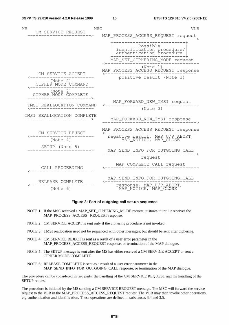
MS MSC VLR CM SERVICE REQUEST -----------------------> MAP_PROCESS_ACCESS_REQUEST request ----------------------------------> +--------------------------+ | Possibly | | identification procedure/| | authentication procedure | +--------------------------+ MAP_SET_CIPHERING_MODE request <---------------------------------- (Note 1) MAP_PROCESS_ACCESS_REQUEST response CM SERVICE ACCEPT <--------------------------------- <----------------------- positive result (Note 1) (Note 2) CIPHER MODE COMMAND <----------------------- (Note 2) CIPHER MODE COMPLETE -----------------------> MAP_FORWARD_NEW_TMSI request TMSI REALLOCATION COMMAND <---------------------------------- <----------------------- (Note 3) TMSI REALLOCATION COMPLETE -----------------------> MAP_FORWARD_NEW_TMSI response ----------------------------------> MAP_PROCESS_ACCESS_REQUEST response CM SERVICE REJECT <--------------------------------- <----------------------- negative result, MAP_U/P_ABORT, (Note 4) MAP_NOTICE, MAP_CLOSE SETUP (Note 5) -----------------------> MAP_SEND_INFO_FOR_OUTGOING_CALL ----------------------------------> request MAP_COMPLETE_CALL request CALL PROCEEDING <---------------------------------- <----------------------- MAP_SEND_INFO_FOR_OUTGOING_CALL RELEASE COMPLETE <---------------------------------- <----------------------- response, MAP_U/P_ABORT, (Note 6) MAP_NOTICE, MAP_CLOSE
Figure 3: Part of outgoing call set-up sequence
NOTE 1: If the MSC received a MAP_SET_CIPHERING_MODE request, it stores it until it receives the MAP_PROCESS_ACCESS_ REQUEST response.
NOTE 2: CM SERVICE ACCEPT is sent only if the ciphering procedure is not invoked.
NOTE 3: TMSI reallocation need not be sequenced with other messages, but should be sent after ciphering.
NOTE 4: CM SERVICE REJECT is sent as a result of a user error parameter in the MAP_PROCESS_ACCESS_REQUEST response, or termination of the MAP dialogue.
NOTE 5: The SETUP message is sent after the MS has either received a CM SERVICE ACCEPT or sent a CIPHER MODE COMPLETE.
NOTE 6: RELEASE COMPLETE is sent as a result of a user error parameter in the MAP_SEND_INFO_FOR_OUTGOING_CALL response, or termination of the MAP dialogue.
The procedure can be considered in two parts: the handling of the CM SERVICE REQUEST and the handling of the SETUP request.
The procedure is initiated by the MS sending a CM SERVICE REQUEST message. The MSC will forward the service request to the VLR in the MAP_PROCESS_ACCESS_REQUEST request. The VLR may then invoke other operations, e.g. authentication and identification. These operations are defined in subclauses 3.4 and 3.5.

ETSI
ETSI TS 129 010 V4.2.0 (2001-12)163GPP TS 29.010 version 4.2.0 Release 1999
If there is a positive outcome for the CM SERVICE REQUEST procedure, the VLR always sends a MAP_PROCESS_ACCESS_REQUEST response. If the request is for a first MM-connection and ciphering is required, the MAP_PROCESS_ACCESS_REQUEST response is preceded by a MAP_SET_CIPHERING_MODE request. In this case the MSC sends a CIPHER MODE COMMAND towards the MS. The interworking for cipher mode setting is described in subclause 4.4. If the request is for an additional MM-connection or for a first MM-connection where ciphering is not required, then the positive MAP_PROCESS_ACCESS_ REQUEST response causes the MSC to send a CM SERVICE ACCEPT message to the MS. After cipher mode setting has been completed or the CM SERVICE ACCEPT message has been returned, the MS will send the SETUP (or EMERGENCY SETUP) message and information retrieval takes place as shown.
A negative outcome for the MAP_PROCESS_ACCESS_REQUEST procedure can be signalled by a MAP_PROCESS_ACCESS_REQUEST response containing a user error parameter, or by terminating the MAP dialogue between the MSC and the VLR.
A positive outcome for the call setup procedure is indicated by a MAP_COMPLETE_CALL request from the VLR to the MSC, which causes the MSC to send a CALL PROCEEDING message towards the MS.
A negative outcome for the call setup procedure can be signalled by a MAP_SEND_INFO_FOR_INCOMING_CALL response or by terminating the dialogue between the MSC and the VLR.
Information element mapping is required between the messages:
- CM SERVICE REQUEST to MAP_PROCESS_ACCESS_REQUEST request;
- SETUP to MAP_SEND_INFO_FOR_OUTGOING CALL request;
- MAP_SEND_INFO_FOR_OUTGOING_CALL response, MAP_U/P_ABORT, MAP_NOTICE or premature MAP_CLOSE to RELEASE COMPLETE or CM SERVICE REJECT.
The information contained in the MAP_COMPLETE_CALL request is not transmitted on the radio interface but is used in the MSC for connecting the call.
The conversion of information elements is as follows:

ETSI
ETSI TS 129 010 V4.2.0 (2001-12)173GPP TS 29.010 version 4.2.0 Release 1999
--------------------------------------------------------------- | 08.08/04.08 09.02 |Notes --------┼------------------------------------------------┼----- Forward | COMPLETE LAYER 3 INFO MAP_PROCESS_ACCESS_ | | (CM SERVICE REQUEST) REQUEST request | | | | CM Service type CM Service type | 1 | Ciphering key CKSN | | sequence number | | Mobile identity TMSI or IMSI or IMEI | | Mobile station | | Classmark 2 - | | | | Cell identifier Current LA Id | 4 | Chosen channel - | | - Access Connection | | Status | 3 --------┼------------------------------------------------┼----- Positive| DTAP(CM SERVICE ACCEPT) MAP_PROCESS_ACCESS_ | result | REQUEST response | 2 --------┼------------------------------------------------┼----- Negative| DTAP(CM SERVICE REJECT) MAP_PROCESS_ACCESS_ | result | REQUEST response | | | | IMSI unknown in VLR Unidentified | | Subscriber | [ | Requested service ??????? | | option not | | subscribed |] | Illegal ME Illegal equipment | | Network failure System failure | | Network failure MAP_U/P_ABORT | | Network failure MAP_NOTICE | | Network failure MAP_CLOSE | --------┼------------------------------------------------┼----- | DTAP(AUTHENTICATION MAP_PROCESS_ACCESS_ | | REJECT) REQUEST response | | | | Illegal subscriber | --------┴------------------------------------------------┴-----
NOTE 1: Indicates, in this case, a mobile originating call establishment or an emergency call establishment.
NOTE 2: The CM SERVICE ACCEPT is sent when the ciphering procedure is not invoked.
NOTE 3: Indicates whether or not an RR-connection exists and whether or not ciphering has been started.
NOTE 4: The Current LA Id parameter is derived by the MSC from the Cell identifier information element.
ETSI
ETSI TS 129 010 V4.2.0 (2001-12)183GPP TS 29.010 version 4.2.0 Release 1999
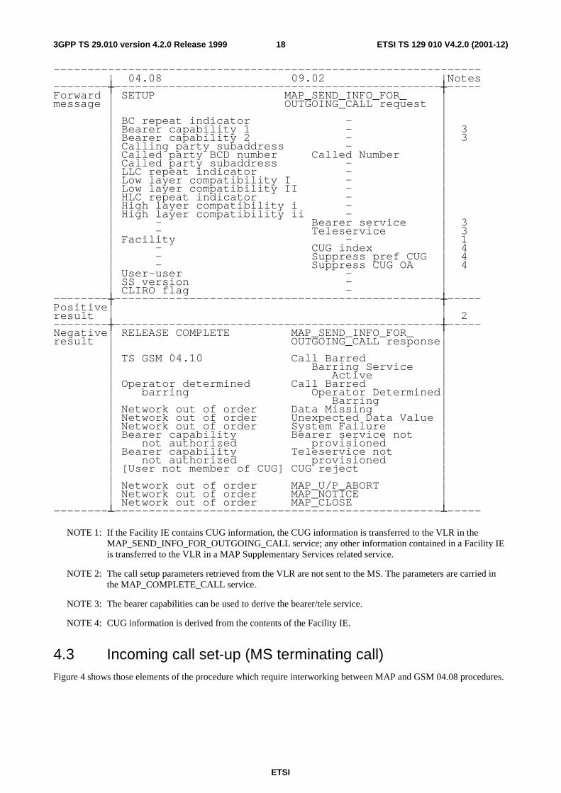
--------------------------------------------------------------- | 04.08 09.02 |Notes --------┼------------------------------------------------┼----- Forward | SETUP MAP_SEND_INFO_FOR_ | message | OUTGOING_CALL request | | | | BC repeat indicator - | | Bearer capability 1 - | 3 | Bearer capability 2 - | 3 | Calling party subaddress - | | Called party BCD number Called Number | | Called party subaddress - | | LLC repeat indicator - | | Low layer compatibility I - | | Low layer compatibility II - | | HLC repeat indicator - | | High layer compatibility i - | | High layer compatibility ii - | | - Bearer service | 3 | - Teleservice | 3 | Facility - | 1 | - CUG index | 4 | - Suppress pref CUG | 4 | - Suppress CUG OA | 4 | User-user - | | SS version - | | CLIRO flag - | --------┼------------------------------------------------┼----- Positive| | result | | 2 --------┼------------------------------------------------┼----- Negative| RELEASE COMPLETE MAP_SEND_INFO_FOR_ | result | OUTGOING_CALL response| | | | TS GSM 04.10 Call Barred | | Barring Service | | Active | | Operator determined Call Barred | | barring Operator Determined| | Barring | | Network out of order Data Missing | | Network out of order Unexpected Data Value | | Network out of order System Failure | | Bearer capability Bearer service not | | not authorized provisioned | | Bearer capability Teleservice not | | not authorized provisioned | | [User not member of CUG] CUG reject | | | | Network out of order MAP_U/P_ABORT | | Network out of order MAP_NOTICE | | Network out of order MAP_CLOSE | --------┴------------------------------------------------┴-----
NOTE 1: If the Facility IE contains CUG information, the CUG information is transferred to the VLR in the
MAP_SEND_INFO_FOR_OUTGOING_CALL service; any other information contained in a Facility IE is transferred to the VLR in a MAP Supplementary Services related service.
NOTE 2: The call setup parameters retrieved from the VLR are not sent to the MS. The parameters are carried in the MAP_COMPLETE_CALL service.
NOTE 3: The bearer capabilities can be used to derive the bearer/tele service.
NOTE 4: CUG information is derived from the contents of the Facility IE.
4.3 Incoming call set-up (MS terminating call) Figure 4 shows those elements of the procedure which require interworking between MAP and GSM 04.08 procedures.

ETSI
ETSI TS 129 010 V4.2.0 (2001-12)193GPP TS 29.010 version 4.2.0 Release 1999
MS MSC VLR +--------------------------+ | Info retrieval | +--------------------------+ MAP_PAGE request or PAGE REQUEST <---------------------------------- <----------------------- MAP_SEARCH_FOR_MS request (Note 1) PAGING RESPONSE -----------------------> MAP_SEARCH_FOR_MS response (Note 2) ----------------------------------> MAP_PROCESS_ACCESS_REQUEST request ----------------------------------> +--------------------------+ | Possibly | | authentication procedure | +--------------------------+ MAP_SET_CIPHERING_MODE request <---------------------------------- (Note 3) MAP_PROCESS_ACCESS_REQUEST response CIPHER MODE COMMAND <--------------------------------- <----------------------- positive result (Note 4) (Note 3) CIPHER MODE COMPLETE -----------------------> MAP_FORWARD_NEW_TMSI request TMSI REALLOCATION COMMAND <---------------------------------- <----------------------- (Note 5) TMSI REALLOCATION COMPLETE -----------------------> MAP_FORWARD_NEW_TMSI response ----------------------------------> MAP_COMPLETE_CALL request SETUP <---------------------------------- <----------------------- MAP_SEND_INFO_FOR_INCOMING_CALL RELEASE COMPLETE <--------------------------------- <----------------------- response negative result, (Note 6) MAP_U/P_ABORT,MAP_NOTICE, MAP_CLOSE
Figure 4: Incoming call set-up
NOTE 1: If an MM connection already exists, the PAGE REQUEST is not sent. If the call can be accepted, the MSC sends a MAP_PROCESS_ACCESS_REQUEST request in response to the MAP_PAGE request. If the call cannot be accepted the MSC sends a MAP_PAGE response containing the error 'busy subscriber'.
NOTE 2: Sent only if MAP_SEARCH_FOR_MS was used.
NOTE 3: Needed only if a ciphered MM-connection does not exist already.
NOTE 4: If the MSC received a MAP_SET_CIPHERING_MODE request, it stores it until it receives the MAP_PROCESS_ACCESS_ REQUEST response.
NOTE 5: TMSI reallocation need not be sequenced with other messages, but should be sent after ciphering.
NOTE 6: RELEASE COMPLETE is sent as a result of a user error parameter in the MAP_SEND_INFO_FOR_OUTGOING_CALL response, or termination of the MAP dialogue.
The paging procedure is controlled by the VLR. It may be followed by authentication (subclause 3.4), ciphering (subclause 4.4) and reallocation of TMSI(subclause 3.6). The SETUP message is sent when the MAP_COMPLETE_CALL request is received.

ETSI
ETSI TS 129 010 V4.2.0 (2001-12)203GPP TS 29.010 version 4.2.0 Release 1999
Normally there is no interworking between the MAP_COMPLETE_CALL request and the SETUP message. However, the MAP_COMPLETE_CALL request may contain a bearer service indication which will be used to establish the bearer capabilities at the MSC. The interworking between the MAP_PAGE request or MAP_SEARCH_FOR_MS request and the BSSMAP PAGING REQUEST message is as follows:
--------------------------------------------------------------- | 08.08/04.08 09.02 |Notes --------┼------------------------------------------------┼----- Forward | PAGING REQUEST MAP_PAGE request or | message | MAP_SEARCH_FOR_MS request | | | | IMSI IMSI | | TMSI TMSI | 1 | Cell identifier Stored LA Id | | list | --------┼------------------------------------------------┼----- Backward| COMPLETE LAYER 3 INFO MAP_PROCESS_ACCESS_ | message | (PAGING RESPONSE) REQUEST request | | | | - CM service type | 2 | Ciphering key CKSN | | sequence number | | Mobile identity TMSI or IMSI | | Mobile station | | classmark 2 - | | Cell Identifier Current LA Id | 3 | - Access connection | | status | | Chosen channel - | --------┴------------------------------------------------┴-----
NOTE 1: If TMSI is included, the TMSI is used as the mobile identity in the GSM 04.08 PAGE REQUEST
message, otherwise the IMSI is used as the mobile identity.
NOTE 2: In this case the MAP CM service type is set to 'mobile terminating call'.
NOTE 3: The Target LA Id parameter is derived by the MSC from the Cell identifier information element.
4.4 Cipher mode setting The interworking is as follows:
--------------------------------------------------------------- | 08.08 09.02 |Notes --------┼------------------------------------------------┼----- Forward | CIPHER MODE COMMAND MAP_SET_CIPHERING_MODE | | request | | | | Cipher mode setting Ciphering mode | | Encryption information Kc | 1 --------┼------------------------------------------------┼----- Positive| CIPHER MODE COMPLETE None | result | | --------┼------------------------------------------------┼----- Negative| CIPHER MODE REJECT None | result | | --------┴------------------------------------------------┴-----
NOTE 1: The key Kc is passed through the BSS to the BTS, but is not passed to the MS.
4.5 Inter-MSC Handover The general principles of the handover procedures are given in GSM 03.09. GSM 09.10 gives the necessary information for interworking between the 3GPP TS 48.008 handover protocol and the GSM 09.02 MAP protocol.
4.5.1 Basic Inter-MSC Handover
When a Mobile Station is handed over between two MSCs, the establishment of a connection between them (described in GSM 03.09) requires interworking between A-Interface and E-Interface.

ETSI
ETSI TS 129 010 V4.2.0 (2001-12)213GPP TS 29.010 version 4.2.0 Release 1999
The signalling at initiation, execution, completion of the Basic Inter-MSC handover procedure is shown in figures 5 to 10 with both possible positive or negative outcomes.
Additionally figures 5b and 5c show the possible interworking when trace related messages are transparently transferred on the E-Interface at Basic Inter-MSC Handover initiation.
BSS-A MSC-A MSC-B | | | |HANDOVER | | |-------------->|MAP PREPARE HANDOVER | |REQUIRED |------------------------>| +----------------+ | |request | |Possible Alloc. | | | | |of a handover | | | | |no. in the VLR-B| | | | +----------------+ | | | | | | BSS-B | | | | | | |HANDOVER REQUEST | | | |------------------>|
Figure 5a: Signalling for Basic Inter-MSC Handover initiation (no trace related messages transferred)
BSS-A MSC-A MSC-B |BSC INVOKE TRACE | |-------------->| | | | | |HANDOVER | | |-------------->|MAP PREPARE HANDOVER | |REQUIRED |------------------------>| +----------------+ | |request(*) | |Possible Alloc. | | | | |of a handover | | | | |no. in the VLR-B| | | | +----------------+ | | | | | | BSS-B | | | | | | |HANDOVER REQUEST | | | |------------------>| | | | | | | |BSC INVOKE TRACE | | | |---------------->(**)
Figure 5b: Signalling for Basic Inter-MSC Handover initiation (BSC invoke trace message transferred)
(*): In that case, HANDOVER REQUEST and BSC INVOKE TRACE messages are included within the AN-APDU parameter.
(**): BSC INVOKE TRACE is forwarded to BSS-B if supported by MSC-B.
BSS-A MSC-A MSC-B | (*) | |HANDOVER | | |-------------->|MAP PREPARE HANDOVER | |REQUIRED |------------------------>| +----------------+ | |request(**) | |Possible Alloc. | | | | |of a handover | | | | |no. in the VLR-B| | | | +----------------+ | | | | | | BSS-B | | | | | | |HANDOVER REQUEST | | | |------------------>| | | | | | | |MSC INVOKE TRACE | | | |--------------->(***)
Figure 5c: Signalling for Basic Inter-MSC Handover initiation (MSC invoke trace message transferred)

ETSI
ETSI TS 129 010 V4.2.0 (2001-12)223GPP TS 29.010 version 4.2.0 Release 1999
(*): Tracing invocation has been received from VLR.
(**): In that case, HANDOVER REQUEST and MSC INVOKE TRACE messages are included within the AN-APDU parameter.
(***): MSC INVOKE TRACE is forwarded to BSS-B if supported by MSC-B.
Possible Positive outcomes:
a) successful radio resources allocation and handover number allocation (if performed):
BSS-A MSC-A MSC-B BSS-B | | | | | | |HANDOVER REQUEST | | | |<------------------| | | |ACKNOWLEDGE | | | MAP PREPARE HANDOVER | | | |<------------------------| | | | response | | | | | | |HANDOVER COMMAND | | |<--------------| | |
b) radio resources allocation queued and successful handover number allocation (if performed). Later successful
radio resources allocation indication:
BSS-A MSC-A MSC-B BSS-B | | | | | | |QUEUING INDICATION | | | |<------------------| | |MAP PREPARE HANDOVER | | | |<------------------------| | | | response | | | | |HANDOVER REQUEST | | | |<------------------| | | |ACKNOWLEDGE | | |MAP PROCESS ACCESS | | | |<------------------------| | HANDOVER COMMAND| SIGNALLING request | | |<--------------| | | | | | |
Figure 6: Signalling for Basic Inter-MSC Handover execution (Positive outcomes)
Possible Negative outcomes:
c) user error detected, or handover number allocation unsuccessful (if performed), or component rejection or dialogue abortion performed by MSC-B:
BSS-A MSC-A MSC-B BSS-B | | | | | |MAP PREPARE HANDOVER response | | |negative result, MAP CLOSE | | |<------------------------| | | |MAP U/P-ABORT | | |HANDOVER REQUIRED | | |<--------------| | | |REJECT (Note 1)| | | | | | |
d) radio resources allocation failure:

ETSI
ETSI TS 129 010 V4.2.0 (2001-12)233GPP TS 29.010 version 4.2.0 Release 1999
BSS-A MSC-A MSC-B BSS-B | | | | | | |HANDOVER FAILURE | | | |<------------------| | |MAP PREPARE HANDOVER | | | |<------------------------| | | | response | | |HANDOVER REQUIRED | | |<--------------| | | |REJECT (Note 1)| | | | | | |
e) radio resources allocation queued and successful handover number allocation (if performed). Later unsuccessful radio resources allocation:
BSS-A MSC-A MSC-B BSS-B | | | | | | |QUEUING INDICATION | | | |<------------------| | |MAP PREPARE HANDOVER | | | |<------------------------| | | | response | | | | | | | | |HANDOVER FAILURE | | | |<------------------| | |MAP PROCESS ACCESS | | | |<------------------------| | | | SIGNALLING request | | |HANDOVER REQUIRED | | |<--------------| | | |REJECT (Note 1)| | |
f) unsuccessful handover execution (Reversion to the old channel):
BSS-A MSC-A MSC-B BSS-B | | | | |HANDOVER | | | |-------------->| | | |FAILURE | | | | |MAP U -ABORT | | | |------------------------>| | | | |CLEAR COMMAND | | | |------------------>| | | | |
Figure 7: Signalling for Basic Inter-MSC Handover execution (Negative outcomes)
NOTE: Possible rejection of the handover because of the negative outcome of MAP or BSSMAP procedure.
BSS-A MSC-A MSC-B BSS-B | | | | | | |HANDOVER COMPLETE | | | |<------------------| | |MAP SEND END SIGNAL request | | |<------------------------| | |CLEAR sCOMMAND | | | |<--------------| | | | | | |
Figure 8: Signalling for Basic Inter-MSC Handover completion
Positive outcome

ETSI
ETSI TS 129 010 V4.2.0 (2001-12)243GPP TS 29.010 version 4.2.0 Release 1999
BSS-A MSC-A MSC-B BSS-B | | | | | |MAP SEND END SIGNAL | | | |------------------------>| | | | response |CLEAR COMMAND | | | |------------------>| | | | (Note 1) |
Figure 9: Signalling for Basic Inter-MSC Handover completion (Positive outcome)
Negative outcome
BSS-A MSC-A MSC-B BSS-B | | | | | | MAP U/P -ABORT | | | |------------------------>| | | | |CLEAR COMMAND | | | |------------------>| | | | |
Figure 10: Signalling for Basic Inter-MSC Handover completion (Negative outcome)
NOTE: From interworking between MAP and BSSMAP point of view.
The handover procedure is normally triggered by BSS-A by sending a HANDOVER REQUIRED message on A-Interface to MSC-A. The invocation of the Basic Inter-MSC handover procedure is performed and controlled by MSC-A. The sending of the MAP Prepare-Handover request to MSC-B is triggered in MSC-A upon receipt of the HANDOVER REQUIRED message. For compatibility reason, the cell identity of the cell where the call is to be handed over in MSC-B area, provided in the HANDOVER REQUIRED message, is mapped into targetCellId MAP parameter and the HANDOVER REQUEST message is encapsulated in the AN-APDU MAP parameter of the Prepare-Handover MAP request. MSC-B can invoke another operation towards the VLR-B (allocation of the handover number described in GSM 09.02).
Additionally, if tracing activity has been invoked, the trace related messages can be transferred on the E-Interface encapsulated in the AN-APDU MAP parameter of the Prepare-Handover Request. If transferred, one complete trace related message at a time shall be included in the AN-APDU MAP parameter after the HANDOVER REQUEST message.
The interworking between Prepare Handover and HANDOVER REQUIRED is as follows:

ETSI
ETSI TS 129 010 V4.2.0 (2001-12)253GPP TS 29.010 version 4.2.0 Release 1999
---------------------------------------------------------------- | 08.08 09.02 |Notes --------┼-------------------------------------------------┼----- Forward | HANDOVER REQUIRED MAP PREPARE HANDOVER request| message | | | -ho-NumberNotRequired| 1 | BSSMAP information -targetCellId | | elements -AN-APDU( | 2 | HANDOVER REQUEST, | | BSC INVOKE TRACE | 3 | or MSC INVOKE TRACE) | --------┼-------------------------------------------------┼----- Positive| MAP PREPARE HANDOVER response| result | | 4 | -handover number | | -AN-APDU( | | QUEUING INDICATION | | or HANDOVER REQUEST| | ACKNOWLEDGE or | | HANDOVER FAILURE) | --------┼-------------------------------------------------┼----- Negative| HANDOVER REQUIRED REJECT MAP PREPARE HANDOVER| 5 result | | | equipment failure System Failure | | equipment failure No Handover Number | | available | | equipment failure UnexpectedDataValue| | equipment failure Data Missing | | | | equipment failure MAP CLOSE | | equipment failure MAP U/P -ABORT | | |
NOTE 1: The ho-NumberNotRequired parameter is included by MSC-A, when MSC-A decides not to use any
circuit connection with MSC-B. No handover number shall be present in the positive result. Any negative response from MSC-B shall not be due to handover number allocation problem.
NOTE 2: The process performed on the BSSMAP information elements received in the HANDOVER REQUIRED message is described in the GSM Recommendation 08.08.
NOTE 3: The process performed on the BSSMAP information elements received in the MSC or BSC INVOKE TRACE message is described in subclause 4.5.6.6.
NOTE 4: The response to the Prepare-Handover request can include in its AN-APDU parameter, identifying the GSM-08.06 protocol, either a BSSMAP QUEUING INDICATION, or a BSSMAP HANDOVER REQUEST ACKNOWLEDGE or a BSSMAP HANDOVER FAILURE.
In the first case, MSC-A shall wait for the radio resources allocation response from MSC-B, transmitted to MSC-A as described in subclause 4.5.4.
In the second case, the positive result triggers in MSC-A the sending on A-Interface of the HANDOVER COMMAND.
In the third case, the positive result triggers in MSC-A one of the following:
- another handover attempt is initiated by MSC-A;
- optionally the sending of the HANDOVER REQUIRED REJECT.
(The possible sending of the HANDOVER REQUIRED REJECT message upon receipt of the HANDOVER FAILURE is out of the scope of GSM 09.10 and lies in 3GPP TS 48.008).
NOTE 5: The possible sending of the HANDOVER REQUIRED REJECT message is described in 3GPP TS 48.008.
The interworking between Send End Signal and HANDOVER COMPLETE in MSC-B is as follows:

ETSI
ETSI TS 129 010 V4.2.0 (2001-12)263GPP TS 29.010 version 4.2.0 Release 1999
---------------------------------------------------------------- | 08.08 09.02 |Notes --------┼-------------------------------------------------┼----- Forward | HANDOVER COMPLETE MAP SEND END SIGNAL request | message | | | -AN-APDU( | | HANDOVER COMPLETE)| | | --------┼-------------------------------------------------┼----- Positive| CLEAR COMMAND MAP SEND END SIGNAL response| result | -Call Control release | 1 --------┼-------------------------------------------------┼----- Negative| CLEAR COMMAND | result | -Call Control release MAP CLOSE | 2 | -Call Control release MAP U/P -ABORT | | |
NOTE 1: The positive empty result triggers the clearing of the Radio Resources on the A-Interface and the release
of the SCCP connection between MSC-B and BSS-B. If a circuit connection is used between MSC-A and MSC-B, the 'Call Control release' clearing cause shall only be given to BSS-B when MSC-B has received a clearing indication on its circuit connection with MSC-A.
NOTE 2: The abortion of the dialogue or the rejection of the component triggers in MSC-B the clearing of its circuit connection with MSC-A, if any, of the Radio Resources on the A-Interface and the release of the SCCP connection between MSC-B and BSS-B.
The interworking between Send End Signal and CLEAR COMMAND in MSC-A is as follows:
---------------------------------------------------------------- | 09.02 08.08 |Notes --------┼-------------------------------------------------┼----- Forward | MAP SEND END SIGNAL CLEAR COMMAND | message | response | | -AN-APDU( - Handover | | HANDOVER COMPLETE) Successful | --------┼-------------------------------------------------┼----- Positive| | result | | --------┼-------------------------------------------------┼----- Negative| | result | |
The interworking between HANDOVER FAILURE in case of reversion to old channel of the MS and User Abort in MSC-A is as follows:
---------------------------------------------------------------- | 08.08 09.02 |Notes --------┼-------------------------------------------------┼----- Forward | HANDOVER FAILURE MAP U -ABORT | message | | | - Reversion to old | | channel | --------┼-------------------------------------------------┼----- Positive| | result | | --------┼-------------------------------------------------┼----- Negative| | result | |
4.5.2 Subsequent Inter-MSC Handover back to MSC-A
When a Mobile Station is being handed over back to MSC-A, the procedure (described in GSM 03.09) requires interworking between A-Interface and E-Interface.
The signalling at initiation, execution and completion of the Subsequent Inter-MSC handover procedure is shown in figures 11 to 15.

ETSI
ETSI TS 129 010 V4.2.0 (2001-12)273GPP TS 29.010 version 4.2.0 Release 1999
BSS-A MSC-B MSC-A | | | |HANDOVER | | |-------------->|MAP PREPARE SUBSEQUENT | |REQUIRED |------------------------>| | |HANDOVER request | | | | BSS-B | | | | | | |HANDOVER REQUEST | | | |------------------>|
Figure 11: Signalling for Subsequent Inter-MSC Handover back to MSC-A initiation
Possible Positive outcomes:
a) successful radio resources allocation:
BSS-A MSC-B MSC-A BSS-B | | | | | | |HANDOVER REQUEST | | | |<------------------| | | |ACKNOWLEDGE | | | MAP PREPARE SUBSEQUENT | | | |<------------------------| | | | HANDOVER response | | |HANDOVER COMMAND | | |<--------------| | |
b) radio resources allocation queued. Later successful radio resources allocation indication:
BSS-A MSC-B MSC-A BSS-B | | |QUEUING INDICATION | | | |<------------------| | | MAP PREPARE SUBSEQUENT | | | |<------------------------| | | | HANDOVER response | | | | |HANDOVER REQUEST | | | |<------------------| | | |ACKNOWLEDGE | | | MAP FORWARD ACCESS | | | |<------------------------| | | | SIGNALLING request | | |HANDOVER COMMAND | | |<--------------| | |
Figure 12: Signalling for Subsequent Inter-MSC Handover back to MSC-A execution (Positive
outcome)
Possible Negative outcomes:
c) user error detected, or component rejection or dialogue abortion performed by MSC-A:
BSS-A MSC-B MSC-A BSS-B | |MAP PREPARE SUBSEQUENT HANDOVER | | |<------------------------| | |HANDOVER REQUIRED response negative result | |<--------------| | | |REJECT (Note 1)| | | | | | |
d) component rejection or dialogue abortion performed by MSC-A:

ETSI
ETSI TS 129 010 V4.2.0 (2001-12)283GPP TS 29.010 version 4.2.0 Release 1999
BSS-A MSC-B MSC-A BSS-B | |MAP CLOSE, MAP U/P ABORT | | | |<------------------------| | |CLEAR COMMAND | | | |<--------------| | | | | | |
e) radio resources allocation failure:
BSS-A MSC-B MSC-A BSS-B | | | HANDOVER FAILURE | | | |<------------------| | |MAP PREPARE SUBSEQUENT | | | |<------------------------| | |HANDOVER REQUIRED HANDOVER response | | |<--------------| | | |REJECT (Note 1)| | |
f) radio resources allocation queued. Later unsuccessful radio resources allocation:
BSS-A MSC-B MSC-A BSS-B | | |QUEUING INDICATION | | | |<------------------| | | MAP PREPARE SUBSEQUENT | | | |<------------------------| | | | HANDOVER response | | | | |HANDOVER FAILURE | | | |<------------------| | | MAP FORWARD ACCESS | | | |<------------------------| | |HANDOVER REQUIRED SIGNALLING request | | |<--------------| | | |REJECT (Note 1)| | |
Figure 13: Signalling for Subsequent Inter-MSC Handover back to MSC-A execution
(Negative outcome)
NOTE 1: Possible rejection of the handover because of the negative outcome of MAP or BSSMAP procedure.
BSS-B MSC-A MSC-B BSS-A | | | | |HANDOVER | | | |-------------->|MAP SEND END SIGNAL | | |COMPLETE |------------------------>| | | | response | | | | |CLEAR COMMAND | | | |------------------>|
Figure 14: Signalling for Subsequent Inter-MSC Handover back to MSC-A completion
(Successful completion of the procedure)
NOTE: Positive outcome case shown in figure 9.
BSS-B MSC-A MSC-B BSS-A | | | | |HANDOVER | | | |-------------->|MAP SEND END SIGNAL | | |COMPLETE |------------------------>| | | | response | | | | | | | |MAP U/P -ABORT | | | |<------------------------| | | | |CLEAR COMMAND | | | |------------------>| | | |(Note 1) |
Figure 15: Signalling for Subsequent Inter-MSC Handover back to MSC-A completion (Unsuccessful
completion of the procedure)
NOTE 1: Abnormal end of the procedure which triggers the clearing of all resources in MSC-B.
The interworking between Prepare Subsequent Handover and HANDOVER REQUIRED is as follows:

ETSI
ETSI TS 129 010 V4.2.0 (2001-12)293GPP TS 29.010 version 4.2.0 Release 1999
---------------------------------------------------------------- | 08.08 09.02 |Notes --------┼-------------------------------------------------┼----- Forward |HANDOVER REQUIRED MAP PREPARE SUBSEQUENT HANDOVER| message | request | 1 | | | -target MSC number | | BSSMAP information -targetCellId | | elements -AN-APDU( | | HANDOVER REQUEST) | --------┼-------------------------------------------------┼----- Positive|HANDOVER REQUIRED MAP PREPARE SUBSEQUENT HANDOVER| result | response | 2 | -AN-APDU( | | QUEUING INDICATION | | or HANDOVER REQUEST| | ACKNOWLEDGE or | | HANDOVER FAILURE) | --------┼-------------------------------------------------┼----- Negative| HANDOVER REQUIRED REJECT MAP PREPARE SUBSEQUENT| 3 result | HANDOVER response | | equipment failure Unknown MSC | | equipment failure Subsequent Handover| | Failure | | equipment failure UnexpectedDataValue| | equipment failure Data Missing | | | | CLEAR COMMAND | | | | equipment failure MAP CLOSE | | equipment failure MAP U/P -ABORT | | |
NOTE 1: The processing performed on the BSSMAP information elements received in the HANDOVER
REQUIRED message is out of the scope of the present document. The target MSC number is provided to MSC-A by MSC-B based on the information received from BSS-B.
NOTE 2: The response to the Prepare-Subsequent-Handover request can include in its AN-APDU parameter, identifying the GSM-0806 protocol, either a BSSMAP QUEUING INDICATION, or a BSSMAP HANDOVER REQUEST ACKNOWLEDGE or a BSSMAP HANDOVER FAILURE.
In the first case, MSC-B shall wait for the radio resources allocation response from MSC-A, transmitted to MSC-B as described in subclause 4.5.4.
In the second case, the positive result triggers in MSC-B the sending on A-Interface of the HANDOVER COMMAND.
In the third case, the positive result triggers in MSC-B one of the following:
- another handover attempt is initiated by MSC-B;
- optionally the sending of the HANDOVER REQUIRED REJECT.
(The possible sending of the HANDOVER REQUIRED REJECT message upon receipt of the HANDOVER FAILURE is out of the scope of GSM 09.10 and lies in 3GPP TS 48.008).
NOTE 3: The possible sending of the HANDOVER REQUIRED REJECT message is described in 3GPP TS 48.008.
The interworking between Send End Signal Result and HANDOVER COMPLETE in MSC-A is as follows:

ETSI
ETSI TS 129 010 V4.2.0 (2001-12)303GPP TS 29.010 version 4.2.0 Release 1999
---------------------------------------------------------------- | 08.08 09.02 |Notes --------┼-------------------------------------------------┼----- Forward | HANDOVER COMPLETE MAP SEND END SIGNAL | message | response | | | --------┼-------------------------------------------------┼----- Positive| | result | | --------┼-------------------------------------------------┼----- Negative| | result | MAP U/P -ABORT | 1 | |
NOTE 1: The abortion of the dialogue ends the handover procedure with MSC-B.
4.5.3 Subsequent Inter-MSC Handover to third MSC
When a Mobile Station is being handed over to a third MSC, the procedure (described in GSM 03.09) does require one specific interworking case in MSC-A (figure 20) between E-Interface from MSC-B and E-Interface from MSC-B' other than the combination of the ones described in the subclause 4.5.1 and 4.5.2.
BSS-A MSC-B MSC-A MSC-B' | | | | |HANDOVER | | | |----------->|MAP PREPARE SUSEQUENT | | |REQUIRED |--------------------->| | | |HANDOVER request |MAP PREPARE | | | |--------------->| | | |HANDOVER request| | | | |+-------+ | | | ||Possib.| | | | ||Alloc. | | | | ||of ho. | | | | ||number | | | | || VLR-B | | | | |+-------+ | | | | BSS-B' | | | | | | | | |HANDOVER | | | | |-------->| | | | |REQUEST | | | | |
Figure 16: Signalling for Subsequent Inter-MSC Handover to third MSC (MSC-B') initiation
Possible Positive outcomes:
a) successful radio resources allocation:
BSS-A MSC-B MSC-A MSC-B' | | | | | | | | BSS-B' | | | | | | | | |HANDOVER | | | | |<--------| | | | |REQUEST | | | | ACKNOWLEDGE | | | | | | | |MAP PREPARE HANDOVER | | | |<---------------| | | |MAP PREPARE SUBSEQUENT| response | | | |<---------------------| | | | |HANDOVER response | | | | HANDOVER | | | | |<-----------| | | | | COMMAND | | | | | | | | |
b) radio resources allocation queued and successful handover number allocation, if performed. Later successful
radio resources allocation indication:

ETSI
ETSI TS 129 010 V4.2.0 (2001-12)313GPP TS 29.010 version 4.2.0 Release 1999
BSS-A MSC-B MSC-A MSC-B' | | | | | | | | BSS-B' | | | | | | | | | QUEUING | | | | |<--------| | | | |INDICAT. | | | | | | | | |MAP PREPARE HANDOVER | | | |<---------------| | | |MAP PREPARE SUBSEQUENT| response | | | |<---------------------| | | | |HANDOVER response | | | | | | |HANDOVER | | | | |<--------| | | | |REQUEST | | | | ACKNOWLEDGE | | | | | | | |MAP PROCESS ACCESS | | | |<---------------| | | |MAP FORWARD ACCESS |SIGNALLING request | | |<---------------------| | | | |SIGNALLING request | | | | HANDOVER | | | | |<-----------| | | | | COMMAND | | | |
Figure 17: Signalling for Subsequent Inter-MSC Handover to third MSC (MSC-B') execution
(Positive outcome)
Possible Negative outcomes:
c) user error detected, or component rejection or dialogue abortion performed by MSC-B':
BSS-A MSC-B MSC-A MSC-B' | | | | | | | | BSS-B' | | |MAP PREPARE HANDOVER | | | |response negative result | | | |MAP CLOSE | | | | |<---------------| | | | |MAP U/P -ABORT | | | |MAP PREPARE SUBSEQUENT| | | | |<---------------------| | | | |HANDOVER response negative | | | HANDOVER |result | | | |<-----------| | | | | REQUIRED | | | | | REJECT | | | | | (Note 1) | | | |
d) radio resources allocation failure:

ETSI
ETSI TS 129 010 V4.2.0 (2001-12)323GPP TS 29.010 version 4.2.0 Release 1999
BSS-A MSC-B MSC-A MSC-B' | | | | | | | | BSS-B' | | | | | | | | |HANDOVER | | | | |<--------| | | | |FAILURE | | | | | | | | |MAP PREPARE HANDOVER | | | |<---------------| | | |MAP PREPARE SUBSEQUENT| response | | | |<---------------------| | | | |HANDOVER response | | | | HANDOVER | | | | |<-----------| | | | | REQUIRED | | | | | REJECT | | | | | (Note 1) | | | |
e) radio resources allocation queued and successful handover number allocation (if performed). Later unsuccessful radio resources allocation:
BSS-A MSC-B MSC-A MSC-B' | | | | | | | | BSS-B' | | | | | | | | | QUEUING | | | | |<--------| | | | |INDICAT. | | | | | | | | |MAP PREPARE HANDOVER | | | |<---------------| | | |MAP PREPARE SUBSEQUENT| response | | | |<---------------------| | | | |HANDOVER response | | | | | | |HANDOVER | | | | |<--------| | | | |FAILURE | | | | | | | | |MAP PROCESS ACCESS | | | |<---------------| | | | |SIGNALLING request | | |MAP FORWARD ACCESS | | | | |<---------------------| | | | |SIGNALLING request | | | | HANDOVER | | | | |<-----------| | | | | REQUIRED | | | | | REJECT | | | | | (Note 1) | | | |
Figure 18: Signalling for Subsequent Inter-MSC Handover to third MSC (MSC-B') execution (Negative
outcome)
NOTE 1: Possible rejection of the handover because of the negative outcome of MAP or BSSMAP procedure.
Positive outcome:

ETSI
ETSI TS 129 010 V4.2.0 (2001-12)333GPP TS 29.010 version 4.2.0 Release 1999
BSS-A MSC-B MSC-A MSC-B' | | | | | | | | BSS-B' | | | | | | | | |HANDOVER | | | | |<--------| | | | |COMPLETE | | | | | | | | |MAP SEND END SIGNAL | | | |<---------------| | | | MAP SEND END SIGNAL | | | | |<---------------------| | | | | response | | | | CLEAR | | | | |<-----------| | | | | COMMAND | | | |
Figure 19: Signalling for Subsequent Inter-MSC Handover to third MSC (MSC-B') completion
(Successful completion of the procedure)
Negative outcome:
BSS-A MSC-B MSC-A MSC-B' | | | | |HANDOVER | | | BSS-B' |----------->| | | | |FAILURE |MAP PROCESS ACCESS | | | | |--------------------->| | | | |SIGNALLING request (Note 1) | | | | | | | | | |MAP U -ABORT | | | | |--------------->| | | | | |CLEAR | | | | |-------->| | | | |COMMAND | | | | | |
Figure 20: Signalling for Subsequent Inter-MSC Handover to third MSC (MSC-B') completion
(Unsuccessful completion of the procedure)
NOTE 1: Specific interworking case detailed below.
The specific interworking case in MSC-A compared to the subclauses 4.5.1 and 4.5.2 occurs between HANDOVER FAILURE encapsulated in a Process Access Signalling from MSC-B and the abortion of the dialogue with MSC-B' in the case of a reversion to old channel of the MS:
---------------------------------------------------------------- | 09.02 09.02 |Notes --------┼-------------------------------------------------┼----- Forward | MAP PROCESS-SIGNALLING | message | request | | | | -AN-APDU( MAP U -ABORT | 1 | HANDOVER FAILURE) | | | --------┼-------------------------------------------------┼----- Positive| | result | | --------┼-------------------------------------------------┼----- Negative| | result | MAP U/P -ABORT | 2 | |
NOTE 1: The abortion of the dialogue triggers in MSC-B' the clearing of the circuit connection with MSC-A, if
any, and of the Resources between MSC-B' and BSS-B'.The abortion of the dialogue ends the handover procedure with MSC-B'.
NOTE 2: The abortion of the dialogue ends the handover procedure with MSC-B.
4.5.4 BSSAP Messages transfer on E-Interface
The following mapping applies to the encapsulation performed in MSC-A.

ETSI
ETSI TS 129 010 V4.2.0 (2001-12)343GPP TS 29.010 version 4.2.0 Release 1999
---------------------------------------------------------------- | 04.08/08.08 09.02 |Notes --------┼-------------------------------------------------┼----- Forward | BSSAP messages MAP FORWARD ACCESS SIGNALLING| message | request | 1 | | | -AN-APDU (BSSAP messages)| --------┼-------------------------------------------------┼----- Positive| | result | | 2 --------┼-------------------------------------------------┼----- Negative| | result | MAP CLOSE | | MAP U/P -ABORT | | |
NOTE 1: Complete BSSAP messages to be sent on MSC-B - BSS-B interface (BSSMAP or DTAP messages) are
embedded into the AN-APDU parameter (see Annex A of 3GPP TS 48.008 for the description of the set of BSSMAP messages).
NOTE 2: The Return Result does not apply. If MSC-B returns a message, this message will arrive in an Invoke: Process Access Signalling.
The following mapping applies to the encapsulation performed in MSC-B.
---------------------------------------------------------------- | 04.08/08.08 09.02 |Notes --------┼-------------------------------------------------┼----- Forward | BSSAP messages MAP PROCESS ACCESS SIGNALLING| message | request | 1 | | | -AN-APDU (BSSAP messages)| --------┼-------------------------------------------------┼----- Positive| | result | | 2 --------┼-------------------------------------------------┼----- Negative| | result | MAP CLOSE | | CLEAR COMMAND | | | | equipment failure MAP U/P -ABORT | 3 | |
NOTE 1: Complete BSSAP messages to be sent to MSC-A (BSSMAP or DTAP messages) are embedded into the
AN-APDU parameter (see 3GPP TS 49.008 for the description of the set of BSSMAP messages).
NOTE 2: The Return Result does not apply. If MSC-A returns a message, this message will arrive in an Invoke: Forward Access Signalling.
NOTE 3: The abortion of the dialogue triggers the clearing of the circuit connection with MSC-A, if any, of the Radio Resources on the A-Interface and the release of the SCCP connection between MSC-B and BSS-B. The clearing of the Radio Resources (the clearing indication received from BSS-B is transmitted to MSC-A) or the loss of the SCCP connection between MSC-B and BSS-B, triggers in MSC-B the abortion of the dialogue on the E-Interface and the clearing of the circuit connection with MSC-A, if any.
4.5.5 Processing in MSC-B, and information transfer on E-interface
The following parameters require processing (e.g. to store the parameter, to internally generate the parameter) in MSC-B. The relevant BSSMAP procedures are mentioned to ease the comprehension, their detailed description is the scope of 3GPP TS 48.008. Each BSSMAP message listed in 3GPP TS 49.008 being transferred on E-interface shall use the mechanisms given in subclause 4.5.4 and is described in 3GPP TS 48.008.
In case of intra-MSC-B handover/relocation and security interworking , after inter-MSC handover from GSM to GSM, the 3G_MSC-B needs additional information to be able to perform security mode and integrity protection procedures. These RANAP informations are transferred between MSC-A and 3G-MSC-B in MAP messages, defined in 3GPP TS 29.002.

ETSI
ETSI TS 129 010 V4.2.0 (2001-12)353GPP TS 29.010 version 4.2.0 Release 1999
4.5.5.1 Encryption Information
A sequence of possible encryption algorithms can be sent to a BSS in Cipher Mode Command or Handover Request. The BSS chooses one of the listed algorithms and reports this back to the MSC in Cipher Mode Complete or Handover Request Acknowledge respectively.
The list of algorithms, the ciphering key and the chosen algorithm shall be stored by MSC-B, and the chosen value sent to MSC-A.
Transfer of Information:
If ciphering has not been performed before Inter-MSC Handover, this will be controlled by MSC-A after the completion of Inter-MSC Handover.
Ciphering control towards MSC-B:
If Ciphering has been performed before Inter-MSC Handover:
- in the Handover Request BSSMAP message (information included).
The Handover Request Acknowledge should in this case contain the indication of the chosen algorithm.
If Ciphering has NOT been performed before Inter-MSC Handover:
- in the Cipher Mode Command procedure between MSC-A and MSC-B.
If the encryption algorithm is changed at an intra-BSS handover in BSS-B this must be reported to MSC-A in:
- the BSSMAP Handover Performed procedure.
If the encryption algorithm is changed at an intra-MSC handover in MSC-B this must be reported to MSC-A in:
- the BSSMAP Handover Performed procedure which shall be initiated by MSC-B on reception from BSS-B of the Handover Complete message (the information being previously received in the Handover Request Acknowledge message).
Note also that the chosen encryption value may be contained in the BSSMAP Assignment Complete message. This may happen if the encryption value changes e.g. at a second assignment during a call (e.g. from TCH to SDCCH).
4.5.5.2 Channel Type
Assignment Request and Handover Request (BSSMAP) may give the BSS a choice, in the same way as the Encryption Algorithm above. Depending on the Channel Type Info, the chosen channel may have impact on subsequent handovers, internal in MSC-B and inter-MSC controlled by MSC-A. Some values in channel Type Info indicate that if a particular channel once has been chosen, the same type must be used for the rest of the call.
The Channel Type, and the characteristics of the chosen channel shall be stored by MSC-B, and the Chosen Channel and/or Speech Version information elements transferred to MSC-A.
Transfer of Information:
Independently of the type of resource (Signalling only (e.g. SDCCH) or TCH) assigned to the MS, the Channel Type Information is transferred to MSC-B in:
- the Handover Request BSSMAP message, and the Chosen Channel and/or Speech Version should be reported back to MSC-A in the Handover Request Acknowledge.
If a new type of resource is to be assigned after Inter-MSC Handover, this can be made with:
- the BSSMAP Assignment procedure between MSC-A and MSC-B (Chosen Channel and/or Speech Version in Assignment Complete).

ETSI
ETSI TS 129 010 V4.2.0 (2001-12)363GPP TS 29.010 version 4.2.0 Release 1999
If the Channel Type (the chosen channel and/or chosen speech version) is changed at an intra-BSS handover in BSS-B this must be reported to MSC-A in:
- the BSSMAP Handover Performed procedure.
If the Channel Type (the chosen channel or chosen speech version) is changed at an intra-MSC handover in MSC-B this must be reported to MSC-A in:
- the BSSMAP Handover Performed procedure which shall be initiated by MSC-B on reception from BSS-B of the Handover Complete message (the information being previously received in the Handover Request Acknowledge message).
4.5.5.3 Classmark
This information shall be stored by MSC-B and might be received either from MSC-A, or from the MS when the MS initiates a Classmark Update.
Transfer of Information due to Classmark received from MSC-A:
This information shall be stored by MSC-B and is received:
- in the Handover Request BSSMAP message.
If a new type of resource is to be assigned after Inter-MSC Handover, Classmark Information MAY be included:
- in the BSSMAP Assignment procedure.
Transfer of Information, due to "Classmark Signalling Procedures".
This information shall be stored by MSC-B and can be received:
- Due to a classmark update, either requested from MSC-A (Classmark Request, Classmark Update), or an MS-Initiated Classmark Update.
This can be carried out either with:
- the BSSMAP Classmark procedure(s).
Apart from these cases there is the "odd" case where a Classmark Update can be received during an Inter-MSC Handover by MSC-B, i.e. before the MS has moved to the new channel controlled by MSC-B. This can be made with transparent transfer of BSSMAP Classmark Update.
4.5.5.4 Downlink DTX-Flag
The parameter shall be stored by MSC-B to be used at internal Handover in MSC-B.
Transfer of Information:
Received by MSC-B from MSC-A in either:
If the MS has already been assigned to a TCH for speech before the Inter-MSC Handover, the DTX-flag should be sent in:
- the Handover Request BSSMAP message;
(if the type of resource is not TCH for speech, the DTX-flag shall not be included).
If a new assignment to a TCH for speech after an Inter-MSC Handover is to be performed, this can be made with:
- the BSSMAP Assignment procedure.
4.5.5.5 Priority
The parameter shall be stored by MSC-B and is received according to below:

ETSI
ETSI TS 129 010 V4.2.0 (2001-12)373GPP TS 29.010 version 4.2.0 Release 1999
Transfer of Information:
Received by MSC-B from MSC-A in:
- the Handover Request BSSMAP message.
If a change is needed after an Inter-MSC Handover with:
- the BSSMAP Assignment procedure.
4.5.5.6 MSC/BSC-Invoke Trace Information Elements
The process to be performed by MSC-B on the information elements of the MSC or BSC Invoke Trace BSSMAP messages is left for further study.
4.5.5.7 LSA Identifier List
The parameter shall be stored by MSC-B and is received according to below:
Transfer of Information:
Received by MSC-B from MSC-A in:
- the Handover Request BSSMAP message.
If a change is needed after an Inter-MSC Handover with:
- the LSA Information BSSMAP message.
4.5.5.8 Selected UMTS Algorithm
After inter-MSC handover, the 3G_MSC-B can perform intra-MSC GSM to UMTS handover. A sequence of possible encryption and integrity protection algorithms, received from the 3G_MSC-A, can be sent to an RNS in Relocation Request or in Security Mode Command in case of cipher mode setting after intra.MSC-B handover from GSM to UMTS. The RNS chooses one of the listed algorithms and reports this back to the 3G_MSC in Relocation Request Acknowledge or Security Mode Complete respectively. The MSC-B provides the Selected UMTS algorithm information to the MSC-A. The Selected UMTS algorithms IE in the MAP Process Access Signalling Request message refers to the Chosen Integrity Protection Algorithm and Chosen Encryption Algorithm, defined in RANAP specification 3GPP TS 25.413
The selected algorithm shall be stored by 3G_MSC-B, and sent to 3G_MSC-A.
Transfer of Information:
If ciphering has not been performed before Inter-MSC Handover, this will be controlled by 3G_MSC-A after the completion of Inter-MSC Handover and possibly after intra-MSC-B handover from GSM to UMTS. In both cases Selected UMTS algorithm information is received by 3G_MSC-A from 3G_MSC-B in:
− The Process Access Signalling Request MAP message.
4.5.5.9 Allowed UMTS Algorithms
In case of GSM-subscriber, the Integrity Protection Information and UMTS Encryption Information are not transferred to the MSC-B during inter-MSC handover. Allowed UMTS algorithms is UMTS information that is required in RANAP Relocation Request and RANAP Security Mode Command, and shall be provided by 3G_MSC-A. 3G_MSC-B needs this information in case of an intra-MSC GSM to UMTS handover and in subsequent security mode setting, after an inter-MSC handover. Therefore 3G_MSC-A must provide this information in case of an inter-MSC GSM to GSM handover. The Allowed UMTS algorithms IE in the MAP Prepare Handover and in the MAP Forward Access Signalling Request messages refers to the Permitted Integrity Protection Algorithms in Integrity Protection Information and Permitted Encryption Algorithms in Encryption Information, defined in RANAP specification 3GPP TS 25.413.
ETSI
ETSI TS 129 010 V4.2.0 (2001-12)383GPP TS 29.010 version 4.2.0 Release 1999
Allowed UMTS algorithms shall be stored by 3G_MSC-B.
Transfer of information:
If ciphering has not been performed before Inter-MSC Handover, this will be controlled by 3G_MSC-A after the completion of Inter-MSC Handover.
Ciphering control towards 3G_MSC-B:
If Ciphering has been performed before Inter-MSC Handover:
− The Prepare Handover Request MAP message.
If Ciphering has NOT been performed before Inter-MSC Handover:
− The Forward Access Signalling Request MAP message.
4.5.6 Overview of the Technical Specifications GSM interworking for the Inter-MSC Handover

ETSI
ETSI TS 129 010 V4.2.0 (2001-12)393GPP TS 29.010 version 4.2.0 Release 1999
╔══════════════════════════════════════════════════════════════════════════════════════════════════╗ ║ PSTN/ISDN ║ ║ ▒▒▒▒▒▒▒▒▒▒▒▒▒▒▒▒▒▒▒▒▒▒▒▒▒▒▒▒▒▒▒▒▒▒▒▒▒▒▒▒▒▒▒▒▒▒▒▒▒▒ ║ ║ ▒ +---------------+ ▒ ║ ║ ==============▒====== | ============= | =============== ▒ ║ ║ PLMN ▒ | | ▒ ║ ║ ▒ V V ▒ ║ ║ ▒▒▒▒▒▒▒▒▒▒▒▒▒▒▒ ▒ ║ ║ ▒ BSS-A MSC-A MSC-B BSS-B ▒ MS ║ ║ ▒ ▒ ║ ║ ▒ +-------+ ▒ +-------+ ║ ║ ▒ | C M | 04.08 (Note) ▒ | C M | ║ ║ ▒ +-------|<------------------------------------>+-------| ║ ║ ▒ ░░░░░░░░░░░░░░░ | M M | ░░░░░░░░░░░░░░░░░░░░░░░░░░░░░░░░░░▒ | M M | ║ ║ ▒ ░+------+ 08.08 +-------| 08.08'+-------+ 08.08 +-------+ ░▒ +-------| ║ ║ ▒ ░| R R |<----->| R R |<=====>| R R |<----->| R R | ░▒ | R R | ║ ║ ▒ ░+------+ +-------+ (Note)+-------+ +-------+ ░▒ +-------+ ║ ║ ▒ ░ Λ Λ Λ Λ ░▒ ║ ║ ▒ ░ | | 09.10 | | ░▒ Note: Subset of 08.08 ║ ║ ▒ ░ | V V | ░▒ procedures as described ║ ║ ▒ ░ |+-----+ 09.02 +-----+| ░▒ in the TS 3GPP TS 48.008. ║ ║ ▒ ░ ||MAP/E|<----->|MAP/E|| ░▒ ║ ║ ▒ ░ |+-----+ +-----+| 03.09░▒ ║ ║ ▒ ░░░░░░░░░░░░░░░░ | ░░░░░░░░░░░░░░░░░░░ | ░░░░░░░░░░░░░░░░░░░▒ Remark: The A-bis interface and ║ ║ ▒▒▒▒▒▒▒▒▒▒▒▒▒▒▒▒▒▒ V ▒▒▒▒▒▒▒▒▒▒▒▒▒▒▒▒▒▒▒ V ▒▒▒▒▒▒▒▒▒▒▒▒▒▒▒▒▒▒▒▒ the link layer ║ ║ +-----------------------+ protocols being out of ║ ║ | T C A P | the scope of this ║ ║ +-----------------------+ Specification are not ║ ║ +------------------------------------------------------+ shown here. ║ ║ | S C C P | ║ ║ +------------------------------------------------------+ ║ ║ +------------------------------------------------------+ ║ ║ | M T P | ║ ║ +------------------------------------------------------+ ║ ╚══════════════════════════════════════════════════════════════════════════════════════════════════╝

ETSI
ETSI TS 129 010 V4.2.0 (2001-12)403GPP TS 29.010 version 4.2.0 Release 1999
4.6 Inter-MSC Handover (UMTS to GSM) The general principles of the handover procedures are given in 3GPP TS 23.009. 3GPP TS 29.010 gives the necessary information for interworking between the 3GPP TS 25.413 RANAP protocol, GSM handover procedures and the 3GPP TS 29.002 MAP protocol. The RANAP protocol is used between the RNS and the 3G-MSC.
The following three principles apply for the Inter-MSC handover UMTS to GSM:
The BSSMAP parameters required for Inter-MSC handover UMTS to GSM are generated as in GSM.
Received BSSMAP parameters, e.g. cause code or Handover command, are mapped to the appropriate RANAP parameters, e.g. cause code transparent container to source RNS.
4.6.1 Basic Inter-MSC Handover
When a Mobile Station is handed over between two MSCs, the establishment of a connection between them (described in 3GPP TS 23.009) requires interworking between A-Interface and E-Interface.
The signalling at initiation, execution, completion of the Basic Inter-MSC handover procedure is shown in figures 21 to 26 with both possible positive or negative outcomes.
Additionally figure 21b shows the possible interworking when the trace related message is transparently transferred on the E-Interface at Basic Inter-MSC Handover initiation.
RNS-A 3G-MSC-A MSC-B | | | |RELOCATION | | |-------------->|MAP PREPARE HANDOVER | |REQUIRED |------------------------>| +----------------+ | |request | |Possible Alloc. | | | | |of a handover | | | | |no. in the VLR-B| | | | +----------------+ | | | | | | BSS-B | | | | | | |HANDOVER REQUEST | | | |------------------>|
Figure 21a: Signalling for Basic Inter-MSC Handover initiation (no trace related messages
transferred)
RNS-A 3G-MSC-A MSC-B | (*) | |RELOCATION | | |-------------->|MAP PREPARE HANDOVER | |REQUIRED |------------------------>| +----------------+ | |request(**) | |Possible Alloc. | | | | |of a handover | | | | |no. in the VLR-B| | | | +----------------+ | | | | | | BSS-B | | | | | | |HANDOVER REQUEST | | | |------------------>| | | | | | | |MSC INVOKE TRACE | | | |--------------->(***)
Figure 21b: Signalling for Basic Inter-MSC Handover initiation (MSC invoke trace message
transferred)
(*): Tracing invocation has been received from VLR.

ETSI
ETSI TS 129 010 V4.2.0 (2001-12)413GPP TS 29.010 version 4.2.0 Release 1999
(**): In that case, HANDOVER REQUEST and MSC INVOKE TRACE messages are included within the AN-APDU parameter.
(***): MSC INVOKE TRACE is forwarded to BSS-B if supported by MSC-B.
Possible Positive outcomes:
a) successful radio resources allocation and handover number allocation (if performed):
RNS-A 3G-MSC-A MSC-B BSS-B | | | | | | |HANDOVER REQUEST | | | |<------------------| | | |ACKNOWLEDGE | | | MAP PREPARE HANDOVER | | | |<------------------------| | | | response | | | | | | |RELOCATION COMMAND | | |<--------------| | |
b) radio resources allocation queued and successful handover number allocation (if performed). Later successful
radio resources allocation indication:
RNS-A 3G-MSC-A MSC-B BSS-B | | | | | | |QUEUING INDICATION | | | |<------------------| | |MAP PREPARE HANDOVER | | | |<------------------------| | | | response | | | | |HANDOVER REQUEST | | | |<------------------| | | |ACKNOWLEDGE | | |MAP PROCESS ACCESS | | | |<------------------------| | RELOCATION COMMAND SIGNALLING request | | |<--------------| | | | | | |
Figure 22: Signalling for Basic Inter-MSC Handover execution (Positive outcomes)
Possible Negative outcomes:
c) user error detected, or handover number allocation unsuccessful (if performed), or component rejection or dialogue abortion performed by MSC-B:
RNS-A 3G-MSC-A MSC-B BSS-B | | | | | |MAP PREPARE HANDOVER response | | |negative result, MAP CLOSE | | |<------------------------| | | |MAP U/P-ABORT | | | | | | |RELOCATION PREPARATION | | |<--------------| | | |FAILURE(Note 1)| | | | | | |
d) radio resources allocation failure:

ETSI
ETSI TS 129 010 V4.2.0 (2001-12)423GPP TS 29.010 version 4.2.0 Release 1999
RNS-A 3G-MSC-A MSC-B BSS-B | | | | | | |HANDOVER FAILURE | | | |<------------------| | |MAP PREPARE HANDOVER | | | |<------------------------| | | | response | | | | | | |RELOCATION PREPARATION | | |<--------------| | | |FAILURE(Note 1)| | | | | | |
e) radio resources allocation queued and successful handover number allocation (if performed). Later unsuccessful radio resources allocation:
RNS-A 3G-MSC-A MSC-B BSS-B | | | | | | |QUEUING INDICATION | | | |<------------------| | |MAP PREPARE HANDOVER | | | |<------------------------| | | | response | | | | | | | | |HANDOVER FAILURE | | | |<------------------| | |MAP PROCESS ACCESS | | | |<------------------------| | | | SIGNALLING request | | | | | | |RELOCATION PREPARATION | | |<--------------| | | |FAILURE(Note 1)| | |
f) unsuccessful handover execution (Reversion to the old radio resources):
RNS-A 3G-MSC-A MSC-B BSS-B | | | | |RELOCATION | | | |-------------->| | | |CANCEL | | | | |MAP U -ABORT | | | |------------------------>| | | | |CLEAR COMMAND | | | |------------------>| |RELOCATION | | | |<--------------| | | |CANCEL ACK | | |
Figure 23: Signalling for Basic Inter-MSC Handover execution (Negative outcomes)
NOTE 1: Possible rejection of the handover because of the negative outcome of MAP or RANAP procedure.
RNS-A 3G-MSC-A MSC-B BSS-B | | | | | | |HANDOVER COMPLETE | | | |<------------------| | |MAP SEND END SIGNAL request | | |<------------------------| | |IU RELEASE COMMAND | | |<--------------| | | | | | |
Figure 24: Signalling for Basic Inter-MSC Handover completion
Positive outcome:

ETSI
ETSI TS 129 010 V4.2.0 (2001-12)433GPP TS 29.010 version 4.2.0 Release 1999
RNS-A 3G-MSC-A MSC-B BSS-B | | | | | |MAP SEND END SIGNAL | | | |------------------------>| | | | response |CLEAR COMMAND | | | |------------------>| | | | (Note 2) |
Figure 25: Signalling for Basic Inter-MSC Handover completion (Positive outcome)
Negative outcome:
RNS-A 3G-MSC-A MSC-B BSS-B | | | | | | MAP U/P -ABORT | | | |------------------------>| | | | |CLEAR COMMAND | | | |------------------>| | | | |
Figure 26: Signalling for Basic Inter-MSC Handover completion (Negative outcome)
NOTE 2: From interworking between MAP and BSSMAP point of view, when the call is released.
The handover procedure is normally triggered by RNS-A by sending a RELOCATION REQUIRED message on Iu-Interface to 3G-MSC-A. The invocation of the Basic Inter-MSC handover procedure is performed and controlled by 3G-MSC-A. The sending of the MAP Prepare-Handover request to MSC-B is triggered in 3G-MSC-A upon receipt of the RELOCATION REQUIRED message. For compatibility reason, the cell identity of the cell where the call is to be handed over in MSC-B area, provided in the RELOCATION REQUIRED message, is mapped into targetCellId MAP parameter and the HANDOVER REQUEST message is encapsulated in the AN-APDU MAP parameter of the Prepare-Handover MAP request. MSC-B can invoke another operation towards the VLR-B (allocation of the handover number described in 3GPP TS 29.002).
Additionally, if tracing activity has been invoked, the trace related message can be transferred on the E-Interface encapsulated in the AN-APDU MAP parameter of the Prepare-Handover Request. If transferred, one complete trace related message at a time shall be included in the AN-APDU MAP parameter after the HANDOVER REQUEST message.
The interworking between Prepare Handover and RELOCATION REQUIRED is as follows:

ETSI
ETSI TS 129 010 V4.2.0 (2001-12)443GPP TS 29.010 version 4.2.0 Release 1999
---------------------------------------------------------------- | 25.413 29.002 |Notes --------┼-------------------------------------------------┼----- Forward | RELOCATION REQUIRED MAP PREPARE HANDOVER request| message | | | -ho-NumberNotRequired| 1 | RANAP information -targetCellId | | elements -AN-APDU( | 2 | HANDOVER REQUEST, | | | | MSC INVOKE TRACE) | --------┼-------------------------------------------------┼----- Positive| RELOCATION CMD MAP PREPARE HANDOVER response| result | | 3 | -handover number | | -AN-APDU( | | QUEUING INDICATION | | or HANDOVER REQUEST| | ACKNOWLEDGE) | | | --------┼-------------------------------------------------┼----- Negative| RELOCATION PREP FAILURE MAP PREPARE HANDOVER| 4 result | | | Relocation failure in System Failure | | target RNC/CN or target system| |” No Handover Number | | available | |” UnexpectedDataValue| |” Data Missing | | | |” MAP CLOSE | |” MAP U/P -ABORT | | |
NOTE 1: The BSSMAP information elements are already stored in 3G-MSC.
The ho-NumberNotRequired parameter is included by 3G-MSC-A, when 3G-MSC-A decides not to use any circuit connection with MSC-B. No handover number shall be present in the positive result. Any negative response from MSC-B shall not be due to handover number allocation problem.
NOTE 2: The process performed on the RANAP information elements received in the RELOCATION REQUIRED message is described in the 3GPP TS 25.413.
NOTE 3: The response to the Prepare-Handover request can include in its AN-APDU parameter, identifying the GSM 08.06 protocol, either a BSSMAP QUEUING INDICATION, or a BSSMAP HANDOVER REQUEST ACKNOWLEDGE.
In the first case, 3G-MSC-A shall wait for the radio resources allocation response from MSC-B, transmitted to 3G-MSC-A as described in subclause 4.5.4.
In the second case, the positive result triggers in 3G-MSC-A the sending on Iu-Interface of the RELOCATION CMD.
In the third case, the positive result triggers in 3G-MSC-A.
NOTE 4: The possible sending of the RELOCATION PREP FAILURE message is described in the 3G 25.413.
(The possible sending of the RELOCATION PREP FAILURE message upon receipt of the HANDOVER FAILURE is out of the scope of the 3GPP TS 29.010 and lies in the 3GPP TS 25.413).
The interworking between Send End Signal and HANDOVER COMPLETE in MSC-B is as follows:

ETSI
ETSI TS 129 010 V4.2.0 (2001-12)453GPP TS 29.010 version 4.2.0 Release 1999
---------------------------------------------------------------- | 08.08 29.002 |Notes --------┼-------------------------------------------------┼----- Forward | HANDOVER COMPLETE MAP SEND END SIGNAL request | message | | | -AN-APDU( | | HANDOVER COMPLETE)| | | --------┼-------------------------------------------------┼----- Positive| CLEAR COMMAND MAP SEND END SIGNAL response| result | -Call Control release | 1 --------┼-------------------------------------------------┼----- Negative| CLEAR COMMAND | result | -Call Control release MAP CLOSE | 2 | -Call Control release MAP U/P -ABORT | | |
NOTE 1: The positive empty result triggers the clearing of the Radio Resources on the A-Interface and the release
of the SCCP connection between MSC-B and BSS-B. If a circuit connection is used between 3G_MSC-A and MSC-B, the 'Call Control release' clearing cause shall only be given to BSS-B when MSC-B has received a clearing indication on its circuit connection with 3G_MSC-A.
NOTE 2: The abortion of the dialogue or the rejection of the component triggers in MSC-B the clearing of its circuit connection with 3G_MSC-A, if any, of the Radio Resources on the A-Interface and the release of the SCCP connection between MSC-B and BSS-B.
The interworking between Send End Signal and IU RELEASE COMMAND in 3G_MSC-A is as follows:
---------------------------------------------------------------- | 29.002 25.413 |Notes --------┼-------------------------------------------------┼----- Forward | MAP SEND END SIGNAL IU RELEASE COMMAND | message | response | | -AN-APDU( - | | HANDOVER COMPLETE) Successful Relocation | --------┼-------------------------------------------------┼----- Positive| | result | | --------┼-------------------------------------------------┼----- Negative| | result | |
The interworking between RELOCATION CANCEL in case of reversion to old channel of the UE and User Abort in 3G-MSC-A is as follows:
---------------------------------------------------------------- | 25.413 29.002 |Notes --------┼-------------------------------------------------┼----- Forward | RELOCATION CANCEL MAP U -ABORT | message | | | -Relocation cancelled | --------┼-------------------------------------------------┼----- Positive| RELOCATION CANCEL ACKNOWLEDGEMENT | result | | --------┼-------------------------------------------------┼----- Negative| | result | |
4.6.2 Subsequent Inter-MSC Handover from 3G-MSC-B back to MSC-A
When a Mobile Station is being handed over back to MSC-A, the procedure (described in TS 23.009) requires interworking between A-Interface, Iu-interface and E-Interface.
The signalling at initiation, execution and completion of the Subsequent Inter-MSC handover procedure is shown in figures 27 to 31.

ETSI
ETSI TS 129 010 V4.2.0 (2001-12)463GPP TS 29.010 version 4.2.0 Release 1999
RNS-A 3G-MSC-B MSC-A | | | |RELOCATION | | |-------------->|MAP PREPARE SUBSEQUENT | |REQUIRED |------------------------>| | |HANDOVER request | | | | BSS-B | | | | | | |HANDOVER REQUEST | | | |------------------>|
Figure 27: Signalling for Subsequent Inter-MSC Handover back to MSC-A initiation
Possible Positive outcomes:
a) successful radio resources allocation:
RNS-A 3G-MSC-B MSC-A BSS-B | | | | | | |HANDOVER REQUEST | | | |<------------------| | | |ACKNOWLEDGE | | | MAP PREPARE SUBSEQUENT | | | |<------------------------| | | | HANDOVER response | | |RELOCATION CMD | | | |<--------------| | |
b) radio resources allocation queued. Later successful radio resources allocation indication:
RNS-A 3G-MSC-B MSC-A BSS-B | | |QUEUING INDICATION | | | |<------------------| | | MAP PREPARE SUBSEQUENT | | | |<------------------------| | | | HANDOVER response | | | | |HANDOVER REQUEST | | | |<------------------| | | |ACKNOWLEDGE | | | MAP FORWARD ACCESS | | | |<------------------------| | | | SIGNALLING request | | |RELOCATION CMD | | | |<--------------| | |
Figure 28: Signalling for Subsequent Inter-MSC Handover back to MSC-A execution (Positive
outcome)
Possible Negative outcomes:
c) user error detected, or component rejection or dialogue abortion performed by MSC-A:
RNS-A 3G-MSC-B MSC-A BSS-B | |MAP PREPARE SUBSEQUENT HANDOVER | | |<------------------------| | |RELOCATION PREP| response negative result| | |<--------------| | | |FAILURE(Note 1)| | | | | | |
d) component rejection or dialogue abortion performed by MSC-A:
RNS-A 3G-MSC-B MSC-A BSS-B | |MAP CLOSE, MAP U/P ABORT | | | |<------------------------| | |IU RELEASE | | | |<--------------| | | | COMMAND | | |
e) radio resources allocation failure:

ETSI
ETSI TS 129 010 V4.2.0 (2001-12)473GPP TS 29.010 version 4.2.0 Release 1999
RNS-A 3G-MSC-B MSC-A BSS-B | | | HANDOVER FAILURE | | | |<------------------| | |MAP PREPARE SUBSEQUENT | | | |<------------------------| | |RELOCATION PREP| HANDOVER response | | |<--------------| | | |FAILURE(Note 1)| | |
f) radio resources allocation queued. Later unsuccessful radio resources allocation:
RNS-A 3G-MSC-B MSC-A BSS-B | | |QUEUING INDICATION | | | |<------------------| | | MAP PREPARE SUBSEQUENT | | | |<------------------------| | | | HANDOVER response | | | | |HANDOVER FAILURE | | | |<------------------| | | MAP FORWARD ACCESS | | | |<------------------------| | |RELOCATION PREP| SIGNALLING request | | |<--------------| | | |FAILURE(Note 1)| | |
Figure 29: Signalling for Subsequent Inter-MSC Handover back to MSC-A execution
(Negative outcome)
NOTE 1: Possible rejection of the handover because of the negative outcome of MAP or BSSMAP procedure.
BSS-B MSC-A 3G-MSC-B RNS-A | | | | |HANDOVER | | | |-------------->|MAP SEND END SIGNAL | | |COMPLETE |------------------------>| | | | response | | | | |Iu RELEASE COMMAND | | | |------------------>|
Figure 30: Signalling for Subsequent Inter-MSC Handover back to MSC-A completion
(Successful completion of the procedure)
NOTE: Positive outcome case shown in figure 9.
BSS-B MSC-A 3G-MSC-B RNS-A | | | | |HANDOVER | | | |-------------->|MAP SEND END SIGNAL | | |COMPLETE |------------------------>| | | | response | | | | | | | |MAP U/P -ABORT | | | |<------------------------| | | | |Iu RELEASE COMMAND | | | |------------------>| | | |(Note 1) |
Figure 31: Signalling for Subsequent Inter-MSC Handover back to MSC-A completion (Unsuccessful
completion of the procedure)
NOTE 1: Abnormal end of the procedure which triggers the clearing of all resources in 3G-MSC-B.
The interworking between Prepare Subsequent Handover and RELOCATION REQUIRED is as follows:

ETSI
ETSI TS 129 010 V4.2.0 (2001-12)483GPP TS 29.010 version 4.2.0 Release 1999
---------------------------------------------------------------- | 25.413 29.002 |Notes --------┼-------------------------------------------------┼----- Forward |REL. REQUIRED MAP PREPARE SUBSEQUENT HANDOVER| message | request | | | | -target MSC number | | -targetCellId | | -AN-APDU( | | HANDOVER REQUEST) | | | | | | RANAP information BSSMAP information | | elements: elements: | | | | MS Classmark 2 CM2 | | Source Id Cell Id (serving) | | Target Id Cell Id (target) | | Cause Cause |1 | MS Classmark 3 CM3 | | | | info stored/generated | | in/by 3G-MSC-B: | | Message Type | | Channel Type | | Speech version | | Priority | | Interference Band | | to be used | | | --------┼-------------------------------------------------┼----- Positive|RELOCATION CMD. MAP PREPARE SUBSEQUENT HANDOVER| result | response | 2 | -AN-APDU( | | QUEUING INDICATION | | or HANDOVER REQUEST| | ACKNOWLEDGE or | | HANDOVER FAILURE) | | | | RANAP information BSSMAP information | | elements: elements: | | L3 information L3 information | | | | | | | --------┼-------------------------------------------------┼----- Negative| REL. PREP. FAILURE MAP PREPARE SUBSEQUENT| 3 result | HANDOVER response | | Relocation Failure in Target CN/RNC or Target System Unknown MSC | | Relocation Failure in Target CN/RNC or Target System Subsequent Handover | | Failure | | Relocation Failure in Target CN/RNC or Target System | | UnexpectedDataValue | | Relocation Failure in Target CN/RNC or Target System Data Missing | | | | Iu RELEASE COMMAND | | | | Relocation Cancelled MAP CLOSE | | Relocation Cancelled MAP U/P -ABORT | | |
NOTE 1: The mapping of cause code values between BSSMAP and RANAP is FFS.
NOTE 2: The response to the Prepare-Subsequent-Handover request can include in its AN-APDU parameter, identifying the GSM 08.06 protocol, a BSSMAP QUEUING INDICATION, or a BSSMAP HANDOVER REQUEST ACKNOWLEDGE or a BSSMAP HANDOVER FAILURE.
In the first case, 3G-MSC-B shall wait for the radio resources allocation response from MSC-A, transmitted to 3G-MSC-B as described in subclause 4.5.4.
In the second case, the positive result triggers in 3GMSC-B the sending on Iu-Interface of the RELOCATION COMMAND.

ETSI
ETSI TS 129 010 V4.2.0 (2001-12)493GPP TS 29.010 version 4.2.0 Release 1999
In the third case, the positive result triggers in 3G-MSC-B the sending of the RELOCATION PREPARATION FAILURE.
NOTE 3: The possible sending of the RELOCATION PREPARATION FAILURE message is described in 3GPP TS 25.413.
The interworking between Send End Signal Result and HANDOVER COMPLETE in MSC-A is as follows:
---------------------------------------------------------------- | 08.08 29.002 |Notes --------┼-------------------------------------------------┼----- Forward | HANDOVER COMPLETE MAP SEND END SIGNAL | message | response | | | --------┼-------------------------------------------------┼----- Positive| | result | | --------┼-------------------------------------------------┼----- Negative| | result | MAP U/P -ABORT | 1 | |
NOTE: The abortion of the dialogue ends the handover procedure with 3G-MSC-B.
4.6.3 Subsequent Inter-MSC Handover to third MSC
When a Mobile Station is being handed over to a third MSC, the procedure (described in 3GPP TS 23.009) does require one specific interworking case in MSC-A between E-Interface from 3G-MSC-B and E-Interface from MSC-B' other than the combination of the ones described in subclauses 4.6.1 and 4.6.2.
RNS-A 3G-MSC-B MSC-A MSC-B' | | | | |RELOCATION | | | |----------->|MAP PREPARE SUBSEQUENT| | |REQUIRED |--------------------->| | | |HANDOVER request |MAP PREPARE | | | |--------------->| | | |HANDOVER request| | | | |+-------+ | | | ||Possib.| | | | ||Alloc. | | | | ||of ho. | | | | ||number | | | | || VLR-B | | | | |+-------+ | | | | BSS-B' | | | | | | | | |HANDOVER | | | | |-------->| | | | |REQUEST | | | | |
Figure 32: Signalling for Subsequent Inter-MSC Handover to third MSC (MSC-B') initiation
Possible Positive outcomes:
a) successful radio resources allocation:

ETSI
ETSI TS 129 010 V4.2.0 (2001-12)503GPP TS 29.010 version 4.2.0 Release 1999
RNS-A 3G-MSC-B MSC-A MSC-B' | | | | | | | | BSS-B' | | | | | | | | |HANDOVER | | | | |<--------| | | | |REQUEST | | | | ACKNOWLEDGE | | | | | | | |MAP PREPARE HANDOVER | | | |<---------------| | | |MAP PREPARE SUBSEQUENT| response | | | |<---------------------| | | | |HANDOVER response | | | | RELOCATION | | | | |<-----------| | | | | COMMAND | | | | | | | | |
b) radio resources allocation queued and successful handover number allocation, if performed. Later successful
radio resources allocation indication:
RNS-A 3G-MSC-B MSC-A MSC-B' | | | | | | | | BSS-B' | | | | | | | | | QUEUING | | | | |<--------| | | | |INDICAT. | | | | | | | | |MAP PREPARE HANDOVER | | | |<---------------| | | |MAP PREPARE SUBSEQUENT| response | | | |<---------------------| | | | |HANDOVER response | | | | | | |HANDOVER | | | | |<--------| | | | |REQUEST | | | | ACKNOWLEDGE | | | | | | | |MAP PROCESS ACCESS | | | |<---------------| | | |MAP FORWARD ACCESS |SIGNALLING request | | |<---------------------| | | | |SIGNALLING request | | | | RELOCATION | | | | |<-----------| | | | | COMMAND | | | |
Figure 33: Signalling for Subsequent Inter-MSC Handover to third MSC (MSC-B') execution
(Positive outcome)
Possible Negative outcomes:
c) user error detected, or component rejection or dialogue abortion performed by MSC-B':

ETSI
ETSI TS 129 010 V4.2.0 (2001-12)513GPP TS 29.010 version 4.2.0 Release 1999
RNS-A 3G-MSC-B MSC-A MSC-B' | | | | | | | | BSS-B' | | |MAP PREPARE HANDOVER | | | |response negative result | | | |MAP CLOSE | | | | |<---------------| | | | |MAP U/P -ABORT | | | |MAP PREPARE SUBSEQUENT| | | | |<---------------------| | | | |HANDOVER response negative | | | RELOCATION |result | | | |<-----------| | | | | PREPARATION| | | | | FAILURE | | | | | (Note 1) | | | |
d) radio resources allocation failure:
RNS-A 3G-MSC-B MSC-A MSC-B' | | | | | | | | BSS-B' | | | | | | | | |HANDOVER | | | | |<--------| | | | |FAILURE | | | | | | | | |MAP PREPARE HANDOVER | | | |<---------------| | | |MAP PREPARE SUBSEQUENT| response | | | |<---------------------| | | | |HANDOVER response | | | | RELOCATION | | | | |<-----------| | | | | PREPARATION| | | | | FAILURE | | | | | (Note 1) | | | |
e) radio resources allocation queued and successful handover number allocation (if performed). Later unsuccessful radio resources allocation:
RNS-A 3G-MSC-B MSC-A MSC-B' | | | | | | | | BSS-B' | | | | | | | | | QUEUING | | | | |<--------| | | | |INDICAT. | | | | | | | | |MAP PREPARE HANDOVER | | | |<---------------| | | |MAP PREPARE SUBSEQUENT| response | | | |<---------------------| | | | |HANDOVER response | | | | | | |HANDOVER | | | | |<--------| | | | |FAILURE | | | | | | | | |MAP PROCESS ACCESS | | | |<---------------| | | | |SIGNALLING request | | |MAP FORWARD ACCESS | | | | |<---------------------| | | | |SIGNALLING request | | | | RELOCATION | | | | |<-----------| | | | | PREPARATION| | | | | FAILURE | | | | | (Note 1) | | | | Figure 34: Signalling for Subsequent Inter-MSC Handover to third MSC (MSC-B') execution (Negative
outcome)

ETSI
ETSI TS 129 010 V4.2.0 (2001-12)523GPP TS 29.010 version 4.2.0 Release 1999
NOTE 1: Possible rejection of the handover because of the negative outcome of MAP or BSSMAP procedure.
Positive outcome:
RNS-A 3G-MSC-B MSC-A MSC-B' | | | | | | | | BSS-B' | | | | | | | | |HANDOVER | | | | |<--------| | | | |COMPLETE | | | | | | | | |MAP SEND END SIGNAL | | | |<---------------| | | | MAP SEND END SIGNAL | | | | |<---------------------| | | | | response | | | | IU-RELEASE | | | | |<-----------| | | | | COMMAND | | | |
Figure 35: Signalling for Subsequent Inter-MSC Handover to third MSC (MSC-B') completion
(Successful completion of the procedure)
Negative outcome:
RNS-A 3G-MSC-B MSC-A MSC-B' | | | | |RELOCATION | | | BSS-B' |----------->| | | | |CANCEL |MAP PROCESS ACCESS | | | | |--------------------->| | | | |SIGNALLING request (Note 1) | | | | | | | | | |MAP U -ABORT | | | | |--------------->| | | | | |CLEAR | | | | |-------->| | | | |COMMAND | |RELOCATION | | | | |<-----------| | | | |CANCEL ACK | | | | | | | | | | | | | | | | | | | | | | | |
Figure 36: Signalling for Subsequent Inter-MSC Handover to third MSC (MSC-B') completion
(Unsuccessful completion of the procedure)
NOTE 1: Specific interworking case detailed below.
The specific interworking case in MSC-A compared to the subclauses 4.5.1 and 4.5.2 occurs between HANDOVER FAILURE encapsulated in a Process Access Signalling from 3G-MSC-B and the abortion of the dialogue with MSC-B' in the case of a reversion to old channel of the MS:

ETSI
ETSI TS 129 010 V4.2.0 (2001-12)533GPP TS 29.010 version 4.2.0 Release 1999
---------------------------------------------------------------- | 29.002 29.002 |Notes --------┼-------------------------------------------------┼----- Forward | MAP PROCESS-SIGNALLING | message | request | | | | -AN-APDU( MAP U -ABORT | 1 | HANDOVER FAILURE) | | | --------┼-------------------------------------------------┼----- Positive| | result | | --------┼-------------------------------------------------┼----- Negative| | result | MAP U/P -ABORT | 2 | |
NOTE 1: The abortion of the dialogue triggers in MSC-B' the clearing of the circuit connection with MSC-A, if
any, and of the Resources between MSC-B' and BSS-B'.The abortion of the dialogue ends the handover procedure with MSC-B'.
NOTE 2: The abortion of the dialogue ends the handover procedure with 3G-MSC-B.
4.6.4 BSSAP Messages transfer on E-Interface
The handling is described in chapter 4.5.4.
4.6.5 Processing in MSC-B, and information transfer on E-interface
The handling is described in chapter 4.5.5.
4.6.6 Cause Code Mapping
When a Mobile Station is handed over between UMTS and GSM, a mapping of the cause codes used in the RANAP and the BSSMAP protocols is needed. The mapping described here is applicable to the BSSMAP protocol even when used inside MAP in the E-interface.
The mapping between the cause codes received in RANAP Relocation Required and the cause codes sent in BSSMAP Handover Request is as follows:
---------------------------------------------------------------- 25.413 08.08 |Notes -------------------------------------------------------┼-------- RELOCATION REQUIRED HANDOVER REQUEST | | -Time critical relocation -Better cell | -Resource optimisation | 1 relocation | -Relocation desirable for -Better cell | radio reasons | -Directed retry -Directed retry | -Any other value -Better cell |
NOTE 1: Cause code not used at inter-system handover.
The mapping between the cause codes received in RANAP Relocation Cancel and the cause codes sent in BSSMAP Clear Command is as follows:

ETSI
ETSI TS 129 010 V4.2.0 (2001-12)543GPP TS 29.010 version 4.2.0 Release 1999
---------------------------------------------------------------- 25.413 08.08 |Notes -------------------------------------------------------┼-------- RELOCATION CANCEL CLEAR COMMAND | | -Trelocprepexpiry -Radio interface | failure, reversion to | old channel | -Interaction with other -Radio interface | procedure failure, reversion to | old channel | -Any other value -Radio interface | failure, reversion to | old channel |
The mapping between the cause codes received in BSSMAP Handover Failure and the cause codes sent in RANAP Relocation Preparation Failure is as follows:
---------------------------------------------------------------- 08.08 25.413 |Notes -------------------------------------------------------┼-------- HANDOVER FAILURE RELOCATION PREP. FAILURE| | -Ciphering algorithm not -Requested ciphering | supported and/or integrity | protection is not | supported | -Circuit pool mismatch | 1 -Equipment failure -Relocation failure in | Target CN/RNC or | target system | -Invalid message contents - Abstract Syntax Error| -No radio resource available -Relocation failure in | Target CN/RNC or | target system | -O and M intervention -O and M intervention | -Radio interface failure, | 2 reversion to old channel | -Radio interface message -Relocation failure in | failure Target CN/RNC or | target system | -Requested speech version -Relocation failure in | unavailable Target CN/RNC or | target system | -Requested terrestrial -Relocation failure in | resource unavailable Target CN/RNC or | target system | -Requested transcoding/rate -Relocation failure in | adaption unavailable Target CN/RNC or | target system | -Switch circuit pool | 1 -Terrestrial circuit already -Relocation failure in | allocated Target CN/RNC or | target system | -Any other value -Relocation failure in | Target CN/RNC or | target system |
NOTE 1: Cause code not used at inter-system handover.
NOTE 2: Cause code not applicable to this traffic case.
4.7 Inter-MSC Handover (GSM to UMTS) The general principles of the handover procedures are given in 3GPP TS 23.009. 3GPP TS 29.010 gives the necessary information for interworking between the 3GPP TS 25.413 RANAP protocol, GSM handover procedures and the 3GPP TS 29.002 MAP protocol. The RANAP protocol is used between the RNS and the 3G_MSC.
The following four principles apply for the Inter-MSC handover GSM to UMTS:
The BSSMAP parameters required for Inter-MSC handover GSM to UMTS are generated as in GSM.

ETSI
ETSI TS 129 010 V4.2.0 (2001-12)553GPP TS 29.010 version 4.2.0 Release 1999
Received RANAP parameters, e.g. cause code or transparent container, are mapped to the appropriate BSSMAP parameters, e.g. cause code or Handover command.
The RANAP parameters required for Inter-MSC handover GSM to UMTS are generated from received or stored GSM parameters.
4.7.1 Basic Inter-MSC Handover
When a Mobile Station is handed over between two MSCs, the establishment of a connection between them (described in 3GPP TS 23.009) requires interworking between A-Interface, Iu-Interface and E-Interface.
The signalling at initiation, execution and completion of the Basic Inter-MSC handover procedure is shown in figures 37 to 42 with both possible positive or negative outcomes.
Additionally figure 37b shows the possible interworking when the trace related message is transparently transferred on the E-Interface at Basic Inter-MSC Handover initiation.
BSS-A MSC-A 3G-MSC-B | | | |HANDOVER | | |-------------->|MAP PREPARE HANDOVER | |REQUIRED |------------------------>| +----------------+ | |request | |Possible Alloc. | | | | |of a handover | | | | |no. in the VLR-B| | | | +----------------+ | | | | | | RNS-B | | | | | | |RELOCATION REQUEST | | | |------------------>|
Figure 37a: Signalling for Basic Inter-MSC Handover initiation (no trace related messages
transferred)
BSS-A MSC-A 3G-MSC-B | (*) | |HANDOVER | | |-------------->|MAP PREPARE HANDOVER | |REQUIRED |------------------------>| +----------------+ | |request (**) | |Possible Alloc. | | | | |of a handover | | | | |no. in the VLR-B| | | | +----------------+ | | | | | | RNS-B | | | | | | |RELOCATION REQUEST | | | |------------------>| | | | | | | |CN INVOKE TRACE | | | |--------------->(***)
Figure 37b: Signalling for Basic Inter-MSC Handover initiation (CN invoke trace message transferred)
(*): Tracing invocation has been received from VLR.
(**): In that case, HANDOVER REQUEST and MSC INVOKE TRACE messages are included within the AN-apdu parameter.
(***): CN INVOKE TRACE is forwarded to RNS-B if supported by 3G_MSC-B.
Possible Positive outcomes: successful radio resources allocation and handover number allocation (if performed):

ETSI
ETSI TS 129 010 V4.2.0 (2001-12)563GPP TS 29.010 version 4.2.0 Release 1999
BSS-A MSC-A 3G-MSC-B RNS-B | | | | | | |RELOCATION REQUEST | | | |<------------------| | | |ACKNOWLEDGE | | | |LOCATION REPORTING | | | |------------------>| | | |CONTROL | | | MAP PREPARE HANDOVER | | | |<------------------------| | | | response | | | | | | |HANDOVER COMMAND | | |<--------------| | |
Figure 38: Signalling for Basic Inter-MSC Handover execution (Positive outcome)
Possible Negative outcomes:
a) user error detected, or handover number allocation unsuccessful (if performed), or component rejection or dialogue abortion performed by 3G_MSC-B:
BSS-A MSC-A 3G-MSC-B RNS-B | | | | | |MAP PREPARE HANDOVER response | | |negative result, MAP CLOSE | | |<------------------------| | | |MAP U/P-ABORT | | | | | | |HANDOVER REQUIRED | | |<--------------| | | |REJECT (Note 1)| | | | | | |
b) radio resources allocation failure:
BSS-A MSC-A 3G-MSC-B RNS-B | | | | | | |RELOCATION FAILURE | | | |<------------------| | |MAP PREPARE HANDOVER | | | |<------------------------| | | | response | | | | | | |HANDOVER REQUIRED | | |<--------------| | | |REJECT (Note 1)| | | | | | |
c) unsuccessful handover execution (Reversion to the old radio resources):
BSS-A MSC-A 3G-MSC-B RNS-B | | | | |HANDOVER | | | |-------------->| | | |FAILURE | | | | |MAP U -ABORT | | | |------------------------>| | | | |IU RELEASE COMMAND | | | |------------------>|
Figure 39: Signalling for Basic Inter-MSC Handover execution (Negative outcomes)
NOTE 1: Possible rejection of the handover because of the negative outcome of MAP or RANAP procedure.
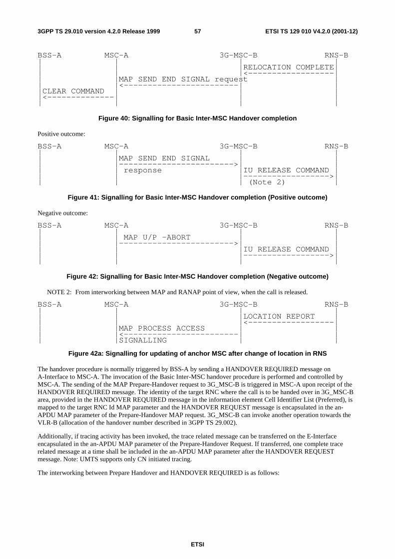
ETSI
ETSI TS 129 010 V4.2.0 (2001-12)573GPP TS 29.010 version 4.2.0 Release 1999
BSS-A MSC-A 3G-MSC-B RNS-B | | | | | | |RELOCATION COMPLETE| | | |<------------------| | |MAP SEND END SIGNAL request | | |<------------------------| | |CLEAR COMMAND | | | |<--------------| | | | | | |
Figure 40: Signalling for Basic Inter-MSC Handover completion
Positive outcome:
BSS-A MSC-A 3G-MSC-B RNS-B | | | | | |MAP SEND END SIGNAL | | | |------------------------>| | | | response |IU RELEASE COMMAND | | | |------------------>| | | | (Note 2) |
Figure 41: Signalling for Basic Inter-MSC Handover completion (Positive outcome)
Negative outcome:
BSS-A MSC-A 3G-MSC-B RNS-B | | | | | | MAP U/P -ABORT | | | |------------------------>| | | | |IU RELEASE COMMAND | | | |------------------>| | | | |
Figure 42: Signalling for Basic Inter-MSC Handover completion (Negative outcome)
NOTE 2: From interworking between MAP and RANAP point of view, when the call is released.
BSS-A MSC-A 3G-MSC-B RNS-B | | | | | | |LOCATION REPORT | | | |<------------------| | |MAP PROCESS ACCESS | | | |<------------------------| | | |SIGNALLING | |
Figure 42a: Signalling for updating of anchor MSC after change of location in RNS
The handover procedure is normally triggered by BSS-A by sending a HANDOVER REQUIRED message on A-Interface to MSC-A. The invocation of the Basic Inter-MSC handover procedure is performed and controlled by MSC-A. The sending of the MAP Prepare-Handover request to 3G_MSC-B is triggered in MSC-A upon receipt of the HANDOVER REQUIRED message. The identity of the target RNC where the call is to be handed over in 3G_MSC-B area, provided in the HANDOVER REQUIRED message in the information element Cell Identifier List (Preferred), is mapped to the target RNC Id MAP parameter and the HANDOVER REQUEST message is encapsulated in the an-APDU MAP parameter of the Prepare-Handover MAP request. 3G_MSC-B can invoke another operation towards the VLR-B (allocation of the handover number described in 3GPP TS 29.002).
Additionally, if tracing activity has been invoked, the trace related message can be transferred on the E-Interface encapsulated in the an-APDU MAP parameter of the Prepare-Handover Request. If transferred, one complete trace related message at a time shall be included in the an-APDU MAP parameter after the HANDOVER REQUEST message. Note: UMTS supports only CN initiated tracing.
The interworking between Prepare Handover and HANDOVER REQUIRED is as follows:

ETSI
ETSI TS 129 010 V4.2.0 (2001-12)583GPP TS 29.010 version 4.2.0 Release 1999
---------------------------------------------------------------- | 08.08 29.002 |Notes --------┼-------------------------------------------------┼----- Forward | HANDOVER REQUIRED MAP PREPARE HANDOVER request| message | | | -ho-NumberNotRequired| 1 | BSSMAP information -target RNC Id | | elements -IMSI | | -Integrity protection| 2 | info | | -Encryption info | | -an-APDU( | 3 | HANDOVER REQUEST, | | MSC INVOKE TRACE) | 4 --------┼-------------------------------------------------┼----- Positive| MAP PREPARE HANDOVER response| result | | 5 | -handover number | | -an-APDU( | | HANDOVER REQUEST | | ACKNOWLEDGE or | | HANDOVER FAILURE) | --------┼-------------------------------------------------┼----- Negative| HANDOVER REQUIRED REJECT MAP PREPARE HANDOVER| 6 result | | | equipment failure System Failure | | equipment failure No Handover Number | | available | | equipment failure UnexpectedDataValue| | equipment failure Data Missing | | | | equipment failure MAP CLOSE | | equipment failure MAP U/P -ABORT | | |
NOTE 1: The ho-NumberNotRequired parameter is included by MSC-A, when MSC-A decides not to use any
circuit connection with 3G_MSC-B. No handover number shall be present in the positive result. Any negative response from 3G_MSC-B shall not be due to handover number allocation problem.
NOTE 2: Integrity protection information, encryption information and IMSI parameters are included by MSC-A, only when the MSC-A uses 29.002 as per release 99. These IEs are not included if the MSC-A is R98 or earlier.
NOTE 3: The process performed on the BSSMAP information elements received in the HANDOVER REQUIRED message is described in the GSM Recommendation 08.08.
NOTE 4: The process performed on the BSSMAP information elements received in the MSC INVOKE TRACE message is described in subclause 4.5.5.6.
NOTE 5: The response to the Prepare-Handover request can include in its an-APDU parameter, identifying the GSM 08.06 protocol, either a BSSMAP HANDOVER REQUEST ACKNOWLEDGE or a BSSMAP HANDOVER FAILURE.
In the first case, the positive result triggers in MSC-A the sending on A-Interface of the HANDOVER COMMAND.
In the second case, the positive result triggers in MSC-A optionally the sending of the HANDOVER REQUIRED REJECT.
(The possible sending of the HANDOVER REQUIRED REJECT message upon receipt of the HANDOVER FAILURE is out of the scope of 3GPP TS 29.010 and lies in 3GPP TS 48.008).
NOTE 6: The possible sending of the HANDOVER REQUIRED REJECT message is described in 3GPP TS 48.008.
The interworking between Prepare Handover and RELOCATION REQUEST in 3G_MSC-B is as follows:

ETSI
ETSI TS 129 010 V4.2.0 (2001-12)593GPP TS 29.010 version 4.2.0 Release 1999
---------------------------------------------------------------- | 29.002 25.413 |Notes --------┼-------------------------------------------------┼----- Forward | MAP PREPARE HANDOVER RELOCATION REQUEST | message | request | | -ho-NumberNotRequired | | -target RNC Id | | -IMSI | | -Integrity protection info | 1 | -Encryption info | | -an-APDU( | | HANDOVER REQUEST, | | MSC INVOKE TRACE) | | | | BSSMAP information RANAP information | | elements: elements: | | | | Channel Type RAB parameters | | Cause Cause | | sRNC to tRNC container sRNC to tRNC container| | | | info stored/generated | | in/by 3G_MSC-B: | | CN domain indicator | | | --------┼-------------------------------------------------┼----- Positive| MAP PREPARE HANDOVER RELOCATION REQUEST ACK | result | response | | -an-APDU( | | HANDOVER REQUEST ACK) | | | | BSSMAP information RANAP information | | elements: elements: | | | | Layer 3 info tRNC to sRNC container| | | --------┼-------------------------------------------------┼----- Negative| MAP PREPARE HANDOVER RELOCATION FAILURE | result | response | | -an-APDU( | | HANDOVER FAILURE) |
| | NOTE 1: Integrity protection information, encryption information and IMSI parameters are included by MSC-A,
only when the MSC-A uses 29.002 as per release 99. These IEs are not included if the MSC-A is R98 or earlier.
The interworking between Send End Signal and RELOCATION COMPLETE in 3G_MSC-B is as follows:
---------------------------------------------------------------- | 25.413 29.002 |Notes --------┼-------------------------------------------------┼----- Forward | RELOCATION COMPLETE MAP SEND END SIGNAL request | message | | | -an-APDU( | | HANDOVER COMPLETE)| | | --------┼-------------------------------------------------┼----- Positive| IU RELEASE COMMAND MAP SEND END SIGNAL response| result | -Normal release | 1 --------┼-------------------------------------------------┼----- Negative| IU RELEASE COMMAND | result | -Normal release MAP CLOSE | 2 | -Normal release MAP U/P -ABORT| | |
NOTE 1: The positive empty result triggers the clearing of the Radio Resources on the Iu-Interface and the release
of the SCCP connection between 3G_MSC-B and RNS-B. If a circuit connection is used between MSC-A and 3G_MSC-B, the 'Normal release' clearing cause shall only be given to RNS-B when 3G_MSC-B has received a clearing indication on its circuit connection with MSC-A.
NOTE 2: The abortion of the dialogue or the rejection of the component triggers in 3G_MSC-B the clearing of its circuit connection with MSC-A, if any, of the Radio Resources on the Iu-Interface and the release of the SCCP connection between 3G_MSC-B and RNS-B.

ETSI
ETSI TS 129 010 V4.2.0 (2001-12)603GPP TS 29.010 version 4.2.0 Release 1999
The interworking between Send End Signal and CLEAR COMMAND in MSC-A is as follows:
---------------------------------------------------------------- | 29.002 08.08 |Notes --------┼-------------------------------------------------┼----- Forward | MAP SEND END SIGNAL CLEAR COMMAND | message | request | | -an-APDU( - Handover | | HANDOVER COMPLETE) Successful | --------┼-------------------------------------------------┼----- Positive| | result | | --------┼-------------------------------------------------┼----- Negative| | result | |
The interworking between HANDOVER FAILURE in case of reversion to old channel of the MS and User Abort in MSC-A is as follows:
---------------------------------------------------------------- | 08.08 29.002 |Notes --------┼-------------------------------------------------┼----- Forward | HANDOVER FAILURE MAP U -ABORT | message | | | - Reversion to old | | channel | --------┼-------------------------------------------------┼----- Positive| | result | | --------┼-------------------------------------------------┼----- Negative| | result | |
4.7.2 Subsequent Inter-MSC Handover from MSC-B back to 3G_MSC-A
When a Mobile Station is being handed over back to 3G_MSC-A, the procedure (described in 3GPP TS 23.009) requires interworking between A-Interface, Iu-Interface and E-Interface.
The signalling at initiation, execution and completion of the Subsequent Inter-MSC handover procedure is shown in figures 43 to 47.
BSS-A MSC-B 3G-MSC-A | | | |HANDOVER | | |-------------->|MAP PREPARE SUBSEQUENT | |REQUIRED |------------------------>| | |HANDOVER request | | | | RNS-B | | | | | | |RELOCATION REQUEST | | | |------------------>|
Figure 43: Signalling for Subsequent Inter-MSC Handover back to 3G_MSC-A initiation
Possible Positive outcomes: successful radio resources allocation:
BSS-A MSC-B 3G-MSC-A RNS-B | | | | | | |RELOCATION REQUEST | | | |<------------------| | | |ACKNOWLEDGE | | | MAP PREPARE SUBSEQUENT | | | |<------------------------| | | | HANDOVER response | | |HANDOVER COMMAND | | |<--------------| | |
Figure 44: Signalling for Subsequent Inter-MSC Handover back to 3G_MSC-A execution (Positive
outcome)

ETSI
ETSI TS 129 010 V4.2.0 (2001-12)613GPP TS 29.010 version 4.2.0 Release 1999
Possible Negative outcomes:
a) user error detected, or component rejection or dialogue abortion performed by 3G_MSC-A:
BSS-A MSC-B 3G-MSC-A RNS-B | |MAP PREPARE SUBSEQUENT HANDOVER | | |<------------------------| | |HANDOVER REQUIRED response negative result | |<--------------| | | |REJECT (Note 1)| | | | | | |
b) component rejection or dialogue abortion performed by 3G_MSC-A:
BSS-A MSC-B 3G-MSC-A RNS-B | |MAP CLOSE, MAP U/P ABORT | | | |<------------------------| | |CLEAR COMMAND | | | |<--------------| | | | | | |
c) radio resources allocation failure:
BSS-A MSC-B 3G-MSC-A RNS-B | | | RELOCATION FAILURE| | | |<------------------| | |MAP PREPARE SUBSEQUENT | | | |<------------------------| | |HANDOVER REQUIRED HANDOVER response | | |<--------------| | | |REJECT (Note 1)| | |
d) unsuccessful relocation execution (reversion to the old radio resources):
BSS-A MSC-B 3G-MSC-A RNS-B |HANDOVER | | | |-------------->| | | |FAILURE |MAP PROCESS ACCESS | | | |------------------------>| | | | SIGNALLING request |IU RELEASE COMMAND | | | |------------------>| | | | |
Figure 45: Signalling for Subsequent Inter-MSC Handover back to 3G_MSC-A execution
(Negative outcome)
NOTE 1: Possible rejection of the handover because of the negative outcome of MAP or BSSMAP procedure.
RNS-B 3G-MSC-A MSC-B BSS-A | | | | |RELOCATION | | | |-------------->|MAP SEND END SIGNAL | | |COMPLETE |------------------------>| | | | response | | | | |CLEAR COMMAND | | | |------------------>|
Figure 46: Signalling for Subsequent Inter-MSC Handover back to 3G_MSC-A completion
(Successful completion of the procedure)
NOTE: Positive outcome case shown in figure 41.

ETSI
ETSI TS 129 010 V4.2.0 (2001-12)623GPP TS 29.010 version 4.2.0 Release 1999
RNS-B 3G-MSC-A MSC-B BSS-A | | | | | |MAP U/P -ABORT | | | |<------------------------| | | | |CLEAR COMMAND | | | |------------------>| | | |(Note 1) |
Figure 47: Signalling for Subsequent Inter-MSC Handover back to 3G_MSC-A completion
(Unsuccessful completion of the procedure)
NOTE 1: Abnormal end of the procedure that triggers the clearing of all resources in MSC-B.
The interworking between Prepare Subsequent Handover and HANDOVER REQUIRED is as follows:
---------------------------------------------------------------- | 08.08 29.002 |Notes --------┼-------------------------------------------------┼----- Forward |HANDOVER REQUIRED MAP PREPARE SUBSEQUENT HANDOVER| message | request | 1 | | | -target MSC number | | BSSMAP information -target RNC Id | | elements -an-APDU( | | HANDOVER REQUEST) | --------┼-------------------------------------------------┼----- Positive|HANDOVER REQUIRED MAP PREPARE SUBSEQUENT HANDOVER| result | response | 2 | -an-APDU( | | HANDOVER REQUEST | | ACKNOWLEDGE or | | HANDOVER FAILURE) | --------┼-------------------------------------------------┼----- Negative| HANDOVER REQUIRED REJECT MAP PREPARE SUBSEQUENT| 3 result | HANDOVER response | | equipment failure Unknown MSC | | equipment failure Subsequent Handover| | Failure | | equipment failure UnexpectedDataValue| | equipment failure Data Missing | | | | CLEAR COMMAND | | | | equipment failure MAP CLOSE | | equipment failure MAP U/P -ABORT | | |
NOTE 1: The processing performed on the BSSMAP information elements received in the HANDOVER
REQUIRED message is out of the scope of the present document. The target MSC number is provided to 3G_MSC-A by MSC-B based on the information received from RNS-B.
NOTE 2: The response to the Prepare-Subsequent-Handover request can include in its an-APDU parameter, identifying the GSM 08.06 protocol, either a BSSMAP HANDOVER REQUEST ACKNOWLEDGE or a BSSMAP HANDOVER FAILURE.
In the first case, the positive result triggers in MSC-B the sending on A-Interface of the HANDOVER COMMAND.
In the second case, the positive result triggers in MSC-B optionally the sending of the HANDOVER REQUIRED REJECT.
(The possible sending of the HANDOVER REQUIRED REJECT message upon receipt of the HANDOVER FAILURE is out of the scope of 3GPP TS 29.010 and lies in 3GPP TS 48.008).
NOTE 3: The possible sending of the HANDOVER REQUIRED REJECT message is described in 3GPP TS 48.008.
The interworking between Prepare Subsequent Handover and RELOCATION REQUEST in 3G_MSC-A is as follows:

ETSI
ETSI TS 129 010 V4.2.0 (2001-12)633GPP TS 29.010 version 4.2.0 Release 1999
---------------------------------------------------------------- | 29.002 25.413 |Notes --------┼-------------------------------------------------┼----- Forward | MAP PREPARE SUB HANDOVER RELOCATION REQUEST | message | request | | -ho-NumberNotRequired | | -target RNC ID | | -an-APDU( | | HANDOVER REQUEST, | | MSC INVOKE TRACE) | | | | BSSMAP information RANAP information | | elements: elements: | | | | Cause Cause | | sRNC to tRNC container sRNC to tRNC container| | | | info stored/generated | | in/by 3G_MSC-A: | | CN domain indicator | | RAB parameters | | Permanent NAS UE id | | Encryption info | | Integrity protection | | info | | | --------┼-------------------------------------------------┼----- Positive| MAP PREPARE SUB HANDOVER RELOCATION REQUEST ACK| result | response | | -an-APDU( | | HANDOVER REQUEST ACK) | | | | BSSMAP information RANAP information | | elements: elements: | | | | Layer 3 info tRNC to sRNC container| | | --------┼-------------------------------------------------┼----- Negative| MAP SUB PREPARE HANDOVER RELOCATION FAILURE | result | response | | -an-APDU( | | HANDOVER FAILURE) | | |
The interworking between HANDOVER FAILURE and MAP Process Signalling Request in 3G_MSC-B is as follows:
---------------------------------------------------------------- | 08.08 29.002 |Notes --------┼-------------------------------------------------┼----- Forward | HANDOVER FAILURE MAP PROCESS-SIGNALLING | message | request | | -an-APDU( | | HANDOVER FAILURE) | | | --------┼-------------------------------------------------┼----- Positive| | result | | --------┼-------------------------------------------------┼----- Negative| | result | | | |
The interworking between Send End Signal Response and RELOCATION COMPLETE in 3G_MSC-A is as follows:

ETSI
ETSI TS 129 010 V4.2.0 (2001-12)643GPP TS 29.010 version 4.2.0 Release 1999
---------------------------------------------------------------- | 25.413 29.002 |Notes --------┼-------------------------------------------------┼----- Forward | RELOCATION COMPLETE MAP SEND END SIGNAL | message | response | | | --------┼-------------------------------------------------┼----- Positive| | result | | --------┼-------------------------------------------------┼----- Negative| | result | MAP U/P -ABORT | 1 | |
NOTE 1: The abortion of the dialogue ends the handover procedure with MSC-B.
4.7.3 Subsequent Inter-MSC Handover to third MSC
When a Mobile Station is being handed over to a third MSC, the procedure (described in 3GPP TS 23.009) does require one specific interworking case in MSC-A (figure 49) between E-Interface from MSC-B and E-Interface from 3G_MSC-B' other than the combination of the ones described in the subclause 4.5.1 and 4.7.2.
BSS-A MSC-B MSC-A 3G-MSC-B' | | | | |HANDOVER | | | |----------->|MAP PREPARE SUBSEQUENT| | |REQUIRED |--------------------->| | | |HANDOVER request |MAP PREPARE | | | |--------------->| | | |HANDOVER request| | | | |+-------+ | | | ||Possib.| | | | ||Alloc. | | | | ||of ho. | | | | ||number | | | | || VLR-B | | | | |+-------+ | | | | RNS-B' | | | | | | | | |RELOCATION | | | |-------->| | | | |REQUEST | | | | |
Figure 45: Signalling for Subsequent Inter-MSC Handover to third MSC (3G_MSC-B') initiation
Possible Positive outcomes: successful radio resources allocation:
BSS-A MSC-B MSC-A 3G-MSC-B' | | | | | | | | RNS-B' | | | | | | | | |RELOCATION | | | |<--------| | | | |REQUEST | | | | ACKNOWLEDGE | | | | | | | | |LOCATION | | | | |-------->| | | | |REPORTING| | | | |CONTROL | | | | | | | | |MAP PREPARE HANDOVER | | | |<---------------| | | |MAP PREPARE SUBSEQUENT| response | | | |<---------------------| | | | |HANDOVER response | | | | HANDOVER | | | | |<-----------| | | | | COMMAND | | | | | | | | |
Figure 46: Signalling for Subsequent Inter-MSC Handover to third MSC (3G_MSC-B') execution
(Positive outcome)

ETSI
ETSI TS 129 010 V4.2.0 (2001-12)653GPP TS 29.010 version 4.2.0 Release 1999
Possible Negative outcomes:
a) user error detected, or component rejection or dialogue abortion performed by MSC-B':
BSS-A MSC-B MSC-A 3G-MSC-B' | | | | | | | | RNS-B' | | |MAP PREPARE HANDOVER | | | |response negative result | | | |MAP CLOSE | | | | |<---------------| | | | |MAP U/P -ABORT | | | |MAP PREPARE SUBSEQUENT| | | | |<---------------------| | | | |HANDOVER response negative | | | HANDOVER |result | | | |<-----------| | | | | REQUIRED | | | | | REJECT | | | | | (Note 1) | | | |
b) radio resources allocation failure:
BSS-A MSC-B MSC-A 3G-MSC-B' | | | | | | | | RNS-B' | | | | | | | | |RELOCATION | | | |<--------| | | | |FAILURE | | | | | | | | |MAP PREPARE HANDOVER | | | |<---------------| | | |MAP PREPARE SUBSEQUENT| response | | | |<---------------------| | | | |HANDOVER response | | | | HANDOVER | | | | |<-----------| | | | | REQUIRED | | | | | REJECT | | | | | (Note 1) | | | |
Figure 47: Signalling for Subsequent Inter-MSC Handover to third MSC (3G_MSC-B') execution
(Negative outcome)
NOTE 1: Possible rejection of the handover because of the negative outcome of MAP or BSSMAP procedure.
Positive outcome:
BSS-A MSC-B MSC-A 3G-MSC-B' | | | | | | | | RNS-B' | | | | | | | | |RELOCATION | | | |<--------| | | | |COMPLETE | | | | | | | | |MAP SEND END SIGNAL | | | |<---------------| | | | MAP SEND END SIGNAL |request | | | |<---------------------| | | | | response | | | | CLEAR | | | | |<-----------| | | | | COMMAND | | | |
Figure 48: Signalling for Subsequent Inter-MSC Handover to third MSC (3G_MSC-B') completion
(Successful completion of the procedure)

ETSI
ETSI TS 129 010 V4.2.0 (2001-12)663GPP TS 29.010 version 4.2.0 Release 1999
Negative outcome:
BSS-A MSC-B MSC-A 3G-MSC-B' | | | | |HANDOVER | | | RNS-B' |----------->| | | | |FAILURE |MAP PROCESS ACCESS | | | | |--------------------->| | | | |SIGNALLING request (Note 1) | | | | | | | | | |MAP U -ABORT | | | | |--------------->| | | | | |IU RELEASE | | | |-------->| | | | |COMMAND | | | | | |
Figure 49: Signalling for Subsequent Inter-MSC Handover to third MSC (3G_MSC-B') completion
(Unsuccessful completion of the procedure)
NOTE: Specific interworking case detailed below.
BSS-A MSC-A 3G-MSC-B' RNS-B' | | | | | | |LOCATION REPORT | | | |<------------------| | |MAP PROCESS ACCESS | | | |<------------------------| | | |SIGNALLING | |
Figure yy: Signalling for updating of anchor MSC after change of location in RNS
The specific interworking case in MSC-A compared to the subclauses 4.5.1 and 4.7.2 occurs between HANDOVER FAILURE encapsulated in a Process Access Signalling from MSC-B and the abortion of the dialogue with 3G_MSC-B' in the case of a reversion to old channel of the MS:
---------------------------------------------------------------- | 29.002 29.002 |Notes --------┼-------------------------------------------------┼----- Forward | MAP PROCESS-SIGNALLING | message | request | | | | -an-APDU( MAP U -ABORT | 1 | HANDOVER FAILURE) | | | --------┼-------------------------------------------------┼----- Positive| | result | | --------┼-------------------------------------------------┼----- Negative| | result | MAP U/P -ABORT | 2 | |
NOTE 1: The abortion of the dialogue triggers in 3G_MSC-B' the clearing of the circuit connection with MSC-A, if
any, and of the Resources between 3G_MSC-B' and RNS-B'. The abortion of the dialogue ends the handover procedure with 3G_MSC-B'.
NOTE 2: The abortion of the dialogue ends the handover procedure with MSC-B.
4.7.4 BSSAP Messages transfer on E-Interface
The handling is described in chapter 4.5.4, additional cases are described in this chapter.
4.7.4.1 Assignment
The interworking between the BSSMAP assignment messages in MAP and the RANAP RAB assignment messages is as follows:
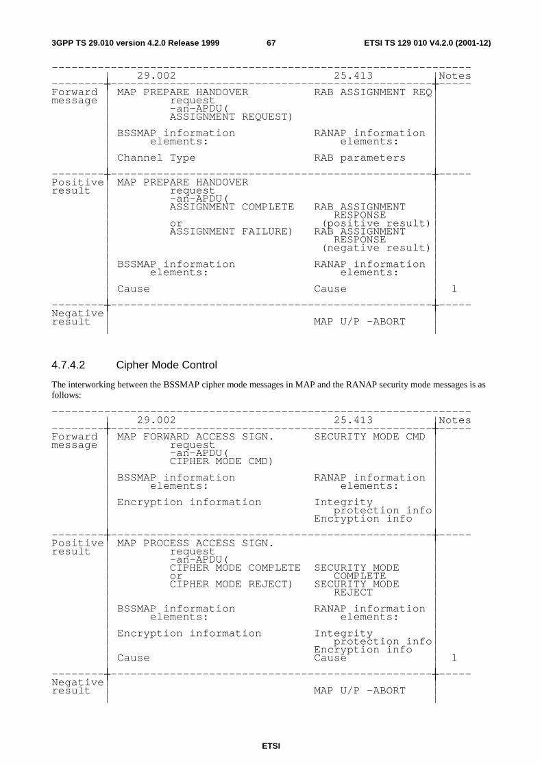
ETSI
ETSI TS 129 010 V4.2.0 (2001-12)673GPP TS 29.010 version 4.2.0 Release 1999
---------------------------------------------------------------- | 29.002 25.413 |Notes --------┼-------------------------------------------------┼----- Forward | MAP PREPARE HANDOVER RAB ASSIGNMENT REQ| message | request | | -an-APDU( | | ASSIGNMENT REQUEST) | | | | BSSMAP information RANAP information | | elements: elements: | | | | Channel Type RAB parameters | | | --------┼-------------------------------------------------┼----- Positive| MAP PREPARE HANDOVER | result | request | | -an-APDU( | | ASSIGNMENT COMPLETE RAB ASSIGNMENT | | RESPONSE | | or (positive result)| | ASSIGNMENT FAILURE) RAB ASSIGNMENT | | RESPONSE | | (negative result)| | | | BSSMAP information RANAP information | | elements: elements: | | | | Cause Cause | 1 | | --------┼-------------------------------------------------┼----- Negative| | result | MAP U/P –ABORT | | |
4.7.4.2 Cipher Mode Control
The interworking between the BSSMAP cipher mode messages in MAP and the RANAP security mode messages is as follows:
---------------------------------------------------------------- | 29.002 25.413 |Notes --------┼-------------------------------------------------┼----- Forward | MAP FORWARD ACCESS SIGN. SECURITY MODE CMD | message | request | | -an-APDU( | | CIPHER MODE CMD) | | | | BSSMAP information RANAP information | | elements: elements: | | | | Encryption information Integrity | | protection info| | Encryption info | | | --------┼-------------------------------------------------┼----- Positive| MAP PROCESS ACCESS SIGN. | result | request | | -an-APDU( | | CIPHER MODE COMPLETE SECURITY MODE | | or COMPLETE | | CIPHER MODE REJECT) SECURITY MODE | | REJECT | | | | BSSMAP information RANAP information | | elements: elements: | | | | Encryption information Integrity | | protection info| | Encryption info | | Cause Cause | 1 | | --------┼-------------------------------------------------┼----- Negative| | result | MAP U/P –ABORT | | |

ETSI
ETSI TS 129 010 V4.2.0 (2001-12)683GPP TS 29.010 version 4.2.0 Release 1999
4.7.4.3 Location Reporting Control
The interworking between the RANAP location report message and the BSSMAP handover performed message in MAP is as follows:
---------------------------------------------------------------- | 25.413 29.002 |Notes --------┼-------------------------------------------------┼----- Forward | LOCATION REPORT MAP PROC. ACC. SIGNALLING | message | | | -an-APDU( | | HANDOVER PERFORMED)| | | | RANAP information BSSMAP information | | elements: elements: | | | | Area identity (SAI) Cell identifier | | Cause Cause | | | --------┼-------------------------------------------------┼----- Positive| | result | | --------┼-------------------------------------------------┼----- Negative| | result | |
4.7.5 Processing in 3G_MSC-B, and information transfer on E-interface
The following parameters require processing (e.g. to store the parameter, to internally generate the parameter) in MSC-B. The relevant BSSMAP procedures are mentioned to ease the comprehension, their detailed description is the scope of 3GPP TS 48.008. Each BSSMAP message listed in 3GPP TS 49.008 being transferred on E-interface shall use the mechanisms given in subclause 4.5.4 and is described in 3GPP TS 48.008.
4.7.5.1 Encryption Information
The list of GSM algorithms, the ciphering key and the chosen algorithm shall be stored by 3G_MSC-B and used for generating the UMTS parameters Encryption Information and Integrity Protection Information if they are not received in MAP Prepare Handover Request (the generation of the UMTS parameters from the GSM parameters is described in TS 33.102).
Transfer of Information:
If ciphering has not been performed before Inter-MSC Handover, this will be controlled by MSC-A after the completion of Inter-MSC Handover.
Ciphering control towards 3G_MSC-B:
If Ciphering has been performed before Inter-MSC Handover:
- in the Handover Request BSSMAP message (information included).
The Handover Request Acknowledge should in this case NOT contain the indication of the chosen algorithm.
If Ciphering has NOT been performed before Inter-MSC Handover:
- in the Cipher Mode Command procedure between MSC-A and 3G_MSC-B.
4.7.5.2 Channel Type
The Channel Type shall be stored by 3G_MSC-B and used for generating RAB parameters.
Transfer of Information:

ETSI
ETSI TS 129 010 V4.2.0 (2001-12)693GPP TS 29.010 version 4.2.0 Release 1999
Independently of the type of resource (Signalling only or traffic channel) assigned to the MS, the Channel Type Information is transferred to 3G_MSC-B in:
- the Handover Request BSSMAP message.
Chosen Channel and/or Speech Version shall NOT be reported back to MSC-A in the Handover Request Acknowledge
If a new type of resource is to be assigned after Inter-MSC Handover, this can be made with:
- the BSSMAP Assignment procedure between MSC-A and 3G_MSC-B.
4.7.5.3 Classmark
This information shall be stored by 3G_MSC-B and might be received from MSC-A.
Transfer of Information due to Classmark received from MSC-A:
This information shall be stored by 3G_MSC-B and is received:
- in the Handover Request BSSMAP message.
If a new type of resource is to be assigned after Inter-MSC Handover, Classmark Information MAY be included:
- in the BSSMAP Assignment procedure.
4.7.5.4 Priority
The parameter shall be stored by 3G_MSC-B and used for generating RAB parameters. It is received as detailed below:
Transfer of Information:
Received by 3G_MSC-B from MSC-A in:
- the Handover Request BSSMAP message.
If a change is needed after an Inter-MSC Handover with:
- the BSSMAP Assignment procedure.
4.7.5.5 MSC-Invoke Trace Information Elements
The process to be performed by 3G_MSC-B on the information elements of the MSC Invoke Trace BSSMAP messages is left for further study.
Note that MSC-A does not forward BSC Invoke Trace in case of GSM to UMTS handover.
4.7.5.6 Selected UMTS Algorithm
A sequence of possible encryption and integrity protection algorithms, received from the 3G_MSC-A, can be sent to an RNS in Relocation Request or in Security Mode Command in case of cipher mode setting after inter-MSC handover from GSM to UMTS. The RNS chooses one of the listed algorithms and reports this back to the 3G_MSC in Relocation Request Acknowledge or Security Mode Complete respectively. The MSC-B provides the Selected UMTS algorithm information to the MSC-A. The Selected UMTS algorithms IE in the MAP Process Access Signalling Request and MAP Prepare Handover Response messages refers to the Chosen Integrity Protection Algorithm and Chosen Encryption Algorithm, defined in RANAP specification 3GPP TS 25.413
The selected algorithm shall be stored by 3G_MSC-B, and sent to 3G_MSC-A.
Transfer of Information:
If ciphering has not been performed before Inter-MSC Handover, this will be controlled by 3G_MSC-A after the completion of Inter-MSC Handover.

ETSI
ETSI TS 129 010 V4.2.0 (2001-12)703GPP TS 29.010 version 4.2.0 Release 1999
If Ciphering has been performed before Inter-MSC Handover, Selected UMTS algorithm information is received by 3G_MSC-A from 3G_MSC-B in:
− The Prepare Handover Response MAP message.
If Ciphering has NOT been performed before Inter-MSC Handover, Selected UMTS algorithm information is received by 3G_MSC-A from 3G_MSC-B in:
− The Process Access Signalling Request MAP message.
4.7.5.7 Allowed UMTS Algorithms
In case of GSM-subscriber, the Integrity Protection Information and UMTS Encryption Information are not transferred to the MSC-B during inter-MSC handover from GSM to UMTS. Allowed UMTS algorithms is UMTS information that is required in RANAP Relocation Request and RANAP Security Mode Command, and shall be provided by 3G_MSC-A. 3G_MSC-B needs this information in case of an inter-MSC GSM to UMTS handover and in subsequent security mode setting, after an inter-MSC GSM to UMTS handover. Therefore 3G_MSC-A must provide this information in case of an inter-MSC GSM to UMTS handover. The Allowed UMTS algorithms IE in the MAP Prepare Handover and in the MAP Forward Access Signalling Request messages refers to the Permitted Integrity Protection Algorithms in Integrity Protection Information and Permitted Encryption Algorithms in Encryption Information, defined in RANAP specification 3GPP TS 25.413.
Allowed UMTS algorithms shall be stored by 3G_MSC-B.
Transfer of information:
If ciphering has not been performed before Inter-MSC Handover, this will be controlled by 3G_MSC-A after the completion of Inter-MSC Handover.
Ciphering control towards 3G_MSC-B:
If Ciphering has been performed before Inter-MSC Handover:
− The Prepare Handover Request MAP message.
If Ciphering has NOT been performed before Inter-MSC Handover:
− The Forward Access Signalling Request MAP message.
4.7.6 Cause Code Mapping
When a Mobile Station is handed over between GSM and UMTS, a mapping of the cause codes used in the BSSMAP and the RANAP protocols is needed. The mapping described here is applicable to the BSSMAP protocol even when used inside MAP in the E-interface.
The mapping between the cause codes received in BSSMAP Handover Required and the cause codes sent in RANAP Relocation Request is as follows:

ETSI
ETSI TS 129 010 V4.2.0 (2001-12)713GPP TS 29.010 version 4.2.0 Release 1999
---------------------------------------------------------------- 08.08 25.413 |Notes -------------------------------------------------------┼-------- HANDOVER REQUIRED RELOCATION REQUEST | | -Better Cell -Time critical reloc. | -Directed retry -Directed retry | -Distance -Time critical reloc. | -Downlink quality -Time critical reloc. | -Downlink strength -Time critical reloc. | -O and M intervention -O and M intervention | -Preemption -RAB pre-empted | -Response to MSC invocation -Time critical reloc. | -Switch circuit pool | 1 -Traffic -Time critical reloc. | -Uplink quality -Time critical reloc. | -Uplink strength -Time critical reloc. | -Any other value -Time critical reloc. |
NOTE 1: Cause code not used at inter-system handover.
The mapping between the cause codes received in BSSMAP Handover Request and the cause codes sent in RANAP Relocation Request is as follows (the mapping is only used for the MAP-E interface):
---------------------------------------------------------------- 08.08 25.413 |Notes -------------------------------------------------------┼-------- HANDOVER REQUEST RELOCATION REQUEST | | -Better Cell -Time critical reloc. | -Directed retry - Directed retry | -Distance -Time critical reloc. | -Downlink quality -Time critical reloc. | -Downlink strength -Time critical reloc. | -O and M intervention -O and M intervention | -Preemption -RAB pre-empted | -Response to MSC invocation -Time critical reloc. | -Switch circuit pool | 1 -Traffic -Time critical reloc. | -Uplink quality -Time critical reloc. | -Uplink strength -Time critical reloc. | -Any other value -Time critical reloc. |
NOTE 1: Cause code not used at inter-system handover.
The mapping between the cause codes received in BSSMAP Handover Failure and the cause codes sent in RANAP Iu Release Command is as follows:
---------------------------------------------------------------- 08.08 25.413 |Notes -------------------------------------------------------┼-------- HANDOVER FAILURE IU RELEASE COMMAND | | -Ciphering algorithm not | 2 supported | -Circuit pool mismatch | 1 -Equipment failure -Relocation cancelled | -Invalid message contents -Abstract Syntax Error | -No radio resource available | 2 -O and M intervention -O and M intervention | -Radio interface failure, -Relocation cancelled | reversion to old channel | -Radio interface message -Relocation cancelled | failure | -Requested speech version | 2 unavailable | -Requested terrestrial | 2 resource unavailable | -Requested transcoding/rate | 2 adaption unavailable | -Switch circuit pool | 1 -Terrestrial circuit already -Relocation cancelled | allocated | -Any other value -Relocation cancelled |
NOTE 1: Cause code not used at inter-system handover.

ETSI
ETSI TS 129 010 V4.2.0 (2001-12)723GPP TS 29.010 version 4.2.0 Release 1999
NOTE 2: Cause code not applicable to this traffic case.
The mapping between the cause codes received in RANAP Relocation Failure and the cause codes sent in BSSMAP Handover Failure is as follows (this mapping is only used for the MAP-E interface):
---------------------------------------------------------------- 25.413 08.08 |Notes -------------------------------------------------------┼-------- RELOCATION FAILURE HANDOVER FAILURE | | -Any value -No radio resource | available |
The mapping between the cause codes received in RANAP Relocation Failure and the cause codes sent in BSSMAP Handover Request Reject is as follows:
---------------------------------------------------------------- 25.413 08.08 |Notes -------------------------------------------------------┼-------- RELOCATION FAILURE HANDOVER REQUIRED REJECT | | -Any value -No radio resource | available |
The mapping between the RANAP and the BSSMAP assignment messages is used in the MAP-E interface. RANAP RAB Assignment Response with successful result is mapped to BSSMAP Assignment Complete; RANAP RAB Assignment Response with unsuccessful result is mapped to BSSMAP Assignment Failure. The mapping between the cause codes received in RANAP RAB Assignment Response and the cause codes sent in BSSMAP Assignment Failure is as follows (this mapping is only used for the MAP-E interface):
---------------------------------------------------------------- 25.413 08.08 |Notes -------------------------------------------------------┼-------- RAB ASSIGNMENT RESPONSE ASSIGNMENT FAILURE | | -Requested traffic class not –No radio resource | available available | -Invalid RAB parameters value –Invalid msg. contents | -Requested max bit rate not –No radio resource | available available | -Requested max bit rate for DL –No radio resource | not available available | -Requested max bit rate for UL –No radio resource | not available available | -Requested guaranteed bit rate –No radio resource | not available available | -Requested guaranteed bit rate –No radio resource | for DL not available available | -Requested guaranteed bit rate –No radio resource | for UL not available available | -Requested transfer delay not –No radio resource | achievable available | -Invalid RAB param. combination–Invalid msg. contents | -Condition violation for SDU –Invalid msg. contents | parameters | -Condition violation for –Invalid msg. contents | traffic handling priority | -Condition violation for –Invalid msg. contents | guaranteed bit rate | -User plane not supported –No radio resource | available | -Iu UP failure –Equipment failure | -Tqueuing expiry –Radio interface message| failure | -Invalid RAB id –Invalid msg. contents | -Request superseeded –No radio resource | available | -Relocation triggered -No radio resource | available | -Any other value –Radio interface message| failure |

ETSI
ETSI TS 129 010 V4.2.0 (2001-12)733GPP TS 29.010 version 4.2.0 Release 1999
The mapping between the cause codes received in RANAP Location Report and the cause codes sent in BSSMAP Handover Performed is as follows (this mapping is only used for the MAP-E interface):
---------------------------------------------------------------- 25.413 08.08 |Notes -------------------------------------------------------┼-------- LOCATION REPORT HANDOVER PERFORMED | | -User restriction start ind. –O&M intervention | -User restriction start ind. –O&M intervention | -Requested report type not | 1 supported | -Any other value -Better cell |
NOTE 1: In this case, no Handover Performed is sent.
4.8 Inter-MSC Relocation The general principles of the relocation procedures are given in Technical Specification TS 23.009. TS 29.010 gives the necessary information for interworking between the TS 25.413 relocation protocol and the TS 29.002 MAP protocol.
For intra UMTS handovers, RANAP is carried over the MAP-E interface instead of BSSAP. Please refer to 3GPP TS 29.108.
4.8.1 Basic Inter-MSC Relocation
When a Mobile Station is relocated between two MSCs, the establishment of a connection between them (described in TS 23.009) requires interworking between Iu-Interface and E-Interface.
The signalling at initiation, execution and completion of the Basic Inter-MSC relocation procedure is shown in figures 50 to 54 with both possible positive or negative outcomes.
Additionally figure 50b shows the possible interworking when trace related messages are transparently transferred on the E-Interface at Basic Inter-MSC Relocation initiation.
RNS-A 3G-MSC-A 3G-MSC-B | | | |RELOCATION | | |-------------->|MAP PREPARE HANDOVER | |REQUIRED |------------------------>| +----------------+ | |request | |Possible Alloc. | | | | |of a relocation| | | | |no. in the VLR-B| | | | +----------------+ | | | | | | RNS-B | | | | | | |RELOCATION REQUEST | | | |------------------>|
Figure 50a: Signalling for Basic Inter-MSC Relocation initiation (no trace related messages
transferred)

ETSI
ETSI TS 129 010 V4.2.0 (2001-12)743GPP TS 29.010 version 4.2.0 Release 1999
RNS-A 3G-MSC-A 3G-MSC-B | (*) | |RELOCATION | | |-------------->|MAP PREPARE HANDOVER | |REQUIRED |------------------------>| +----------------+ | |request (**) | |Possible Alloc. | | | | |of a relocation | | | | |no. in the VLR-B| | | | +----------------+ | | | | | | RNS-B | | | | | | |RELOCATION REQUEST | | | |------------------>| | | | | | | |CN INVOKE TRACE | | | |--------------->(***)
Figure 50b: Signalling for Basic Inter-MSC Relocation initiation (CN invoke trace message
transferred)
(*): Tracing invocation has been received from VLR.
(**): In that case, RELOCATION REQUEST and CN INVOKE TRACE messages are included within the AN-apdu parameter.
(***): CN INVOKE TRACE is forwarded to RNS-B if supported by 3G_MSC-B.
Possible Positive outcomes: successful radio resources allocation and relocation numbers allocation (if performed):
RNS-A 3G-MSC-A 3G-MSC-B RNS-B | | | | | | |RELOCATION REQUEST | | | |<------------------| | | |ACKNOWLEDGE | | | MAP PREPARE HANDOVER | | | |<------------------------| | | | response | | | | | | |RELOCATION COMMAND | | |<--------------| | |
Possible Negative outcomes:
a) user error detected, or relocation numbers allocation unsuccessful (if performed), or component rejection or dialogue abortion performed by 3G_MSC-B:

ETSI
ETSI TS 129 010 V4.2.0 (2001-12)753GPP TS 29.010 version 4.2.0 Release 1999
RNS-A 3G-MSC-A 3G-MSC-B RNS-B | | | | | |MAP PREPARE HANDOVER response | | |negative result, MAP CLOSE | | |<------------------------| | | |MAP U/P-ABORT | | |RELOCATION PREPARATION | | |<--------------| | | |FAILURE | MAP CLOSE | | | |------------------------>| | | | | |
b) radio resources allocation failure:
RNS-A 3G-MSC-A 3G-MSC-B RNS-B | | | | | | |RELOCATION FAILURE | | | |<------------------| | |MAP PREPARE HANDOVER | | | |<------------------------| | | | response | | |RELOCATION PREPARATION | | |<--------------| | | |FAILURE | | | | | | |
c) radio resources allocation partial failure (3G_MSC-A decides to reject the relocation):
RNS-A 3G-MSC-A 3G-MSC-B RNS-B | | | | | | |RELOCATION REQUEST | | | |<------------------| | |MAP PREPARE HANDOVER | ACK | | |<------------------------| | | | response | | |RELOCATION PREPARATION | | |<--------------| | | |FAILURE | | | | | | |
d) unsuccessful relocation execution (relocation cancelled):
RNS-A 3G-MSC-A 3G-MSC-B RNS-B | | | | |RELOCATION | | | |-------------->| | | |CANCEL | | | | |MAP U -ABORT | | | |------------------------>| | | | |IU RELEASE COMMAND | |RELOCATION | |------------------>| |<--------------| | | |CANCEL ACK | | | | | | |
Figure 51: Signalling for Basic Inter-MSC Relocation execution (Negative outcomes)
RNS-A 3G-MSC-A 3G-MSC-B RNS-B | | | | | | |RELOCATION COMPLETE| | | |<------------------| | |MAP SEND END SIGNAL request | | |<------------------------| | |IU RELEASE COMMAND | | |<--------------| | | | | | |
Figure 52: Signalling for Basic Inter-MSC Relocation completion

ETSI
ETSI TS 129 010 V4.2.0 (2001-12)763GPP TS 29.010 version 4.2.0 Release 1999
Positive outcome
RNS-A 3G-MSC-A 3G-MSC-B RNS-B | | | | | |MAP SEND END SIGNAL | | | |------------------------>| | | | response |IU RELEASE COMMAND | | | |------------------>| | | | (Note 1) |
Figure 53: Signalling for Basic Inter-MSC Relocation completion (Positive outcome)
NOTE: From interworking between MAP and RANAP point of view.
Negative outcome:
RNS-A 3G-MSC-A 3G-MSC-B RNS-B | | | | | | MAP U/P -ABORT | | | |------------------------>| | | | |IU RELEASE COMMAND | | | |------------------>| | | | |
Figure 54: Signalling for Basic Inter-MSC Relocation completion (Negative outcome)
The relocation procedure is normally triggered by RNS-A by sending a RELOCATION REQUIRED message on Iu-Interface to 3G_MSC-A. The invocation of the Basic Inter-MSC relocation procedure is performed and controlled by 3G_MSC-A. The sending of the MAP Prepare-Handover request to 3G_MSC-B is triggered in 3G_MSC-A upon receipt of the RELOCATION REQUIRED message. The identity of the target RNC where the call is to be handed over in 3G_MSC-B area, provided in the RELOCATION REQUIRED message, is mapped to the target RNC Id MAP parameter and the RELOCATION REQUEST message is encapsulated in the an-APDU MAP parameter of the Prepare-Handover MAP request. 3G_MSC-B can invoke another operation towards the VLR-B (allocation of the relocation numbers described in 3GPP TS 29.002).
Additionally, if tracing activity has been invoked, the trace related messages can be transferred on the E-Interface encapsulated in the an-APDU MAP parameter of the Prepare-Handover Request. If transferred, one complete trace related message at a time shall be included in the an-APDU MAP parameter after the RELOCATION REQUEST message.
The interworking between Prepare Handover and RELOCATION REQUIRED is as follows:

ETSI
ETSI TS 129 010 V4.2.0 (2001-12)773GPP TS 29.010 version 4.2.0 Release 1999
---------------------------------------------------------------- | 25.413 29.002 |Notes --------┼-------------------------------------------------┼----- Forward | RELOCATION REQUIRED MAP PREPARE HANDOVER request| message | | | -ho-NumberNotRequired| 1 | -target RNC Id | | RANAP information -Radio Resource Info | | elements -an-APDU( | | RELOCATION REQUEST, | 2 | CN INVOKE TRACE) | --------┼-------------------------------------------------┼----- Positive| MAP PREPARE HANDOVER response | result | | 3 | -relocation numbers | | -an-APDU( | | RELOCATION COMMAND RELOCATION REQUEST | | ACKNOWLEDGE | | or | | RELOCATION PREP FAILURE RELOCATION FAILURE)| | | --------┼-------------------------------------------------┼----- Negative| RELOCATION PREP FAILURE MAP PREPARE HANDOVER| result | | | Unspecified failure System Failure | | Unspecified failure No Handover Number | | available | | Unspecified failure UnexpectedDataValue| | Unspecified failure Data Missing | | | | Unspecified failure MAP CLOSE | | Unspecified failure MAP U/P -ABORT | | |
NOTE 1: The RANAP information elements are already stored in 3G_MSC.
The ho-NumberNotRequired parameter is included by 3G_MSC-A, when 3G_MSC-A decides not to use any circuit connection with 3G_MSC-B. No relocation numbers shall be present in the positive result. Any negative response from 3G_MSC-B shall not be due to relocation number allocation problem.
NOTE 2: The process performed on the RANAP information elements received in the RELOCATION REQUIRED message is described in the 3GPP TS 25.413.
NOTE 3: The response to the Prepare-Handover request can include in its an-APDU parameter, identifying the 3GPP TS 25.413 protocol, either a RANAP RELOCATION REQUEST ACKNOWLEDGE or a RANAP RELOCATION FAILURE.
In the first case, the positive result triggers in 3G_MSC-A the sending on Iu-Interface of the RELOCATION CMD.
In the second case, the positive result triggers in 3G_MSC-A the sending of the RELOCATION PREP FAILURE.
The interworking between Send End Signal and RELOCATION COMPLETE in 3G_MSC-B is as follows:

ETSI
ETSI TS 129 010 V4.2.0 (2001-12)783GPP TS 29.010 version 4.2.0 Release 1999
---------------------------------------------------------------- | 25.413 29.002 |Notes --------┼-------------------------------------------------┼----- Forward | RELOCATION COMPLETE MAP SEND END SIGNAL request | message | | | -an-APDU( | | RELOCATION COMPL) | | | --------┼-------------------------------------------------┼----- Positive| IU RELEASE COMMAND MAP SEND END SIGNAL response| result | -Normal release | 1 --------┼-------------------------------------------------┼----- Negative| IU RELEASE COMMAND | result | -Normal release MAP CLOSE | 2 | -Normal release MAP U/P -ABORT | | |
NOTE 1: The positive empty result triggers the clearing of the Radio Resources on the Iu-Interface and the release
of the SCCP connection between 3G_MSC-B and RNS-B. If a circuit connection is used between 3G_MSC-A and 3G_MSC-B, the 'Normal release' clearing cause shall only be given to RNS-B when 3G_MSC-B has received a clearing indication on its circuit connection with 3G_MSC-A.
NOTE 2: The abortion of the dialogue or the rejection of the component triggers in 3G_MSC-B the clearing of its circuit connection with 3G_MSC-A, if any, of the Radio Resources on the Iu-Interface and the release of the SCCP connection between 3G_MSC-B and RNS-B.
The interworking between Send End Signal and IU RELEASE COMMAND in 3G_MSC-A is as follows:
---------------------------------------------------------------- | 29.002 25.413 |Notes --------┼-------------------------------------------------┼----- Forward | MAP SEND END SIGNAL IU RELEASE COMMAND | message | request | | -an-APDU( - Successful | | RELOCATION COMPLETE) Relocation | --------┼-------------------------------------------------┼----- Positive| | result | | --------┼-------------------------------------------------┼----- Negative| | result | |
The interworking between RELOCATION CANCEL in case of relocation cancelled and User Abort in 3G-MSC-A is as follows:
---------------------------------------------------------------- | 25.413 29.002 |Notes --------┼-------------------------------------------------┼----- Forward | RELOCATION CANCEL MAP U -ABORT | message | | | - Relocation | | cancelled | --------┼-------------------------------------------------┼----- Positive| RELOCATION CANCEL ACKNOWLEDGEMENT | result | | --------┼-------------------------------------------------┼----- Negative| | result | |
4.8.2 Subsequent Inter-MSC Relocation back to 3G_MSC-A
When a Mobile Station is being relocated back to 3G_MSC-A, the procedure (described in TS 23.009) requires interworking between Iu-Interface and E-Interface.
The signalling at initiation, execution and completion of the Subsequent Inter-MSC relocation procedure is shown in figures 55 to 59.

ETSI
ETSI TS 129 010 V4.2.0 (2001-12)793GPP TS 29.010 version 4.2.0 Release 1999
RNS-A 3G-MSC-B 3G-MSC-A | | | |RELOCATION | | |-------------->|MAP PREPARE SUBSEQUENT | |REQUIRED |------------------------>| | |HANDOVER request | | | | RNS-B | | | | | | |RELOCATION REQUEST | | | |------------------>|
Figure 55: Signalling for Subsequent Inter-MSC Relocation back to 3G_MSC-A initiation
Possible Positive outcomes: successful radio resources allocation:
RNS-A 3G-MSC-B 3G-MSC-A RNS-B | | | | | | |RELOCATION REQUEST | | | |<------------------| | | |ACKNOWLEDGE | | | MAP PREPARE SUBSEQUENT | | | |<------------------------| | | | HANDOVER response | | |RELOCATION COMMAND | | |<--------------| | |
Figure 56: Signalling for Subsequent Inter-MSC Relocation back to 3G_MSC-A execution (Positive
outcome)
Possible Negative outcomes:
a) user error detected, or component rejection or dialogue abortion performed by 3G_MSC-A:
RNS-A 3G-MSC-B 3G-MSC-A RNS-B | |MAP PREPARE SUBSEQUENT HANDOVER | | |<------------------------| | |RELOCATION PREP| response negative result | |<--------------| | | |FAILURE (Note 1) | | | | | |
b) component rejection or dialogue abortion performed by 3G_MSC-A:
RNS-A 3G-MSC-B 3G-MSC-A RNS-B | |MAP CLOSE, MAP U/P ABORT | | | |<------------------------| | |IU RELEASE COMMAND | | |<--------------| | | | | | |
c) radio resources allocation failure:
RNS-A 3G-MSC-B 3G-MSC-A RNS-B | | | RELOCATION FAILURE| | | |<------------------| | |MAP PREPARE SUBSEQUENT | | | |<------------------------| | |RELOCATION PREP| HANDOVER response | | |<--------------| | | |FAILURE | | |
d) radio resources allocation partial failure (3G_MSC-A decides to reject the relocation):
RNS-A 3G-MSC-B 3G-MSC-A RNS-B | | | RELOCATION REQUEST| | | |<------------------| | |MAP PREPARE SUBSEQUENT | ACK | | |<------------------------| | |RELOCATION PREP| HANDOVER response | | |<--------------| | | |FAILURE | | |

ETSI
ETSI TS 129 010 V4.2.0 (2001-12)803GPP TS 29.010 version 4.2.0 Release 1999
e) unsuccessful relocation execution (relocation cancelled):
RNS-A 3G-MSC-B 3G-MSC-A RNS-B |RELOCATION | | | |-------------->| | | |CANCEL |MAP PROCESS ACCESS | | | |------------------------>| | | | SIGNALLING request |IU RELEASE COMMAND | | | |------------------>| | | |IU RELEASE COMPLETE| | | |<------------------| | |MAP FORWARD ACCESS | | | |<------------------------| | | RELOCATION | SIGNALLING request | | |<--------------| | | |CANCEL ACK | | |
Figure 57: Signalling for Subsequent Inter-MSC Relocation back to 3G_MSC-A execution
(Negative outcome)
RNS-A 3G-MSC-B 3G-MSC-A RNS-B | | | | | | |RELOCATION | | |MAP SEND END SIGNAL |<------------------| | |<------------------------|COMPLETE | | | response | | |IU RELEASE CMD | | | |<--------------| | |
Figure 58: Signalling for Subsequent Inter-MSC Relocation back to 3G_MSC-A completion
(Successful completion of the procedure)
NOTE: Positive outcome case shown in figure 53.
RNS-A 3G-MSC-B 3G-MSC-A RNS-B | | | | | |MAP U/P -ABORT | | | |<------------------------| | | | |IU RELEASE COMMAND | | | |------------------>| | | |(Note 1) |
Figure 59: Signalling for Subsequent Inter-MSC Relocation back to 3G_MSC-A completion
(Unsuccessful completion of the procedure)
NOTE: Abnormal end of the procedure that triggers the clearing of all resources in 3G_MSC-B.
The interworking between Prepare Subsequent Handover and RELOCATION REQUIRED is as follows:

ETSI
ETSI TS 129 010 V4.2.0 (2001-12)813GPP TS 29.010 version 4.2.0 Release 1999
---------------------------------------------------------------- | 25.413 29.002 |Notes --------┼-------------------------------------------------┼----- Forward |REL. REQUIRED MAP PREPARE SUBSEQUENT HANDOVER| message | request | | | | -target MSC number | | -target RNC Id | | RANAP information -an-APDU( | 1 | elements RELOCATION REQ) | | | | | --------┼-------------------------------------------------┼----- Positive| MAP PREPARE SUBSEQUENT HANDOVER| result | response | 2 | -an-APDU( | |RELOCATION CMD. RELOCATION REQUEST | | ACKNOWLEDGE | | or | |RELOCATION PREP FAILURE RELOCATION FAILURE)| | | --------┼-------------------------------------------------┼----- Negative| REL. PREP. FAILURE MAP PREPARE SUBSEQUENT| result | HANDOVER response | | Unspecified failure Unknown MSC | | Unspecified failure Subsequent Handover| | Failure | | Unspecified failure UnexpectedDataValue| | Unspecified failure Data Missing | | | | Iu RELEASE COMMAND MAP CLOSE | | MAP U/P –ABORT | | Unspecified failure | | Unspecified failure | | |
NOTE 1: The processing performed on the RANAP information elements received in the RELOCATION
REQUIRED message is out of the scope of the present document. The target MSC number is provided to 3G_MSC-A by 3G_MSB-B based on the information received from RNS-B.
NOTE 2: The response to the Prepare-Subsequent-Handover request can include in its an-APDU parameter, identifying the 3GPP TS 25.413 protocol, a RANAP RELOCATION REQUEST ACKNOWLEDGE or a RANAP RELOCATION FAILURE.
In the first case, the positive result triggers in 3G_MSC-B the sending on Iu-Interface of the RELOCATION COMMAND.
In the second case, the positive result triggers in 3G_MSC-B the sending of the RELOCATION PREPARATION FAILURE.
The interworking between RELOCATION CANCEL and MAP Process Signalling Request in 3G_MSC-A is as follows:
---------------------------------------------------------------- | 29.002 25.413 |Notes --------┼-------------------------------------------------┼----- Forward | MAP PROCESS-SIGNALLING IU RELEASE COMMAND | message | request | | -an-APDU( | | RELOCATION CANCEL) | | | --------┼-------------------------------------------------┼----- Positive| MAP FORWARD-SIGNALLING IU RELEASE COMPLETE| result | request | | -an-APDU( | | RELOCATION CANCEL ACK) | | | --------┼-------------------------------------------------┼----- Negative| | result | | | |
The interworking between RELOCATION CANCEL and MAP Process Signalling Request in 3G_MSC-B is as follows:

ETSI
ETSI TS 129 010 V4.2.0 (2001-12)823GPP TS 29.010 version 4.2.0 Release 1999
---------------------------------------------------------------- | 25.413 29.002 |Notes --------┼-------------------------------------------------┼----- Forward | RELOCATION CANCEL MAP PROCESS-SIGNALLING | message | request | | -an-APDU( | | RELOCATION CANCEL) | | | --------┼-------------------------------------------------┼----- Positive| RELOCATION CANCEL ACK MAP FORWARD-SIGNALLING | result | request | | -an-APDU( | | RELOCATION CANCEL ACK)| | | --------┼-------------------------------------------------┼----- Negative| | result | | | |
The interworking between Send End Signal Result and RELOCATION COMPLETE in 3G_MSC-A is as follows:
---------------------------------------------------------------- | 25.413 29.002 |Notes --------┼-------------------------------------------------┼----- Forward | RELOCATION COMPLETE MAP SEND END SIGNAL | message | response | | | --------┼-------------------------------------------------┼----- Positive| | result | | --------┼-------------------------------------------------┼----- Negative| | result | MAP U/P -ABORT | 1
NOTE: The abortion of the dialogue ends the relocation procedure with 3G_MSC-B.
4.8.3 Subsequent Inter-MSC Relocation to third MSC
When a Mobile Station is being relocated to a third MSC, the procedure (described in 3GPP TS 23.009) does require one specific interworking case in 3G_MSC-A (figure 64) between E-Interface from 3G_MSC-B and E-Interface from 3G_MSC-B' other than the combination of the ones described in the subclause 4.8.1 and 4.8.2.
RNS-A 3G-MSC-B 3G-MSC-A 3G-MSC-B' | | | | |RELOCATION | | | |----------->|MAP PREPARE SUBSEQUENT| | |REQUIRED |--------------------->| | | |HANDOVER request |MAP PREPARE | | | |--------------->| | | |HANDOVER request| | | | |+-------+ | | | ||Possib.| | | | ||Alloc. | | | | ||of relo| | | | ||number | | | | || VLR-B | | | | |+-------+ | | | | RNS-B' | | | | | | | | |RELOCATION | | | |-------->| | | | |REQUEST | | | | | |
Figure 60: Signalling for Subsequent Inter-MSC Relocation to third MSC (3G_MSC-B') initiation
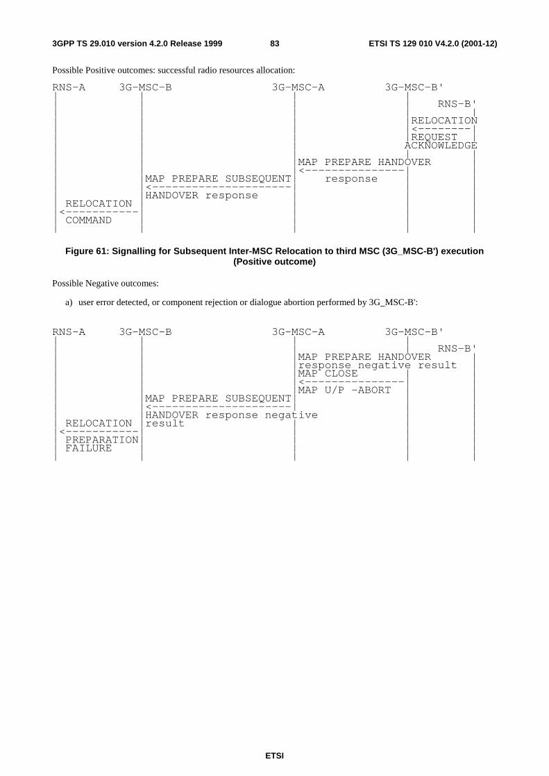
ETSI
ETSI TS 129 010 V4.2.0 (2001-12)833GPP TS 29.010 version 4.2.0 Release 1999
Possible Positive outcomes: successful radio resources allocation:
RNS-A 3G-MSC-B 3G-MSC-A 3G-MSC-B' | | | | | | | | RNS-B' | | | | | | | | |RELOCATION | | | |<--------| | | | |REQUEST | | | | ACKNOWLEDGE | | | | | | | |MAP PREPARE HANDOVER | | | |<---------------| | | |MAP PREPARE SUBSEQUENT| response | | | |<---------------------| | | | |HANDOVER response | | | | RELOCATION | | | | |<-----------| | | | | COMMAND | | | | | | | | |
Figure 61: Signalling for Subsequent Inter-MSC Relocation to third MSC (3G_MSC-B') execution
(Positive outcome)
Possible Negative outcomes:
a) user error detected, or component rejection or dialogue abortion performed by 3G_MSC-B':
RNS-A 3G-MSC-B 3G-MSC-A 3G-MSC-B' | | | | | | | | RNS-B' | | |MAP PREPARE HANDOVER | | | |response negative result | | | |MAP CLOSE | | | | |<---------------| | | | |MAP U/P -ABORT | | | |MAP PREPARE SUBSEQUENT| | | | |<---------------------| | | | |HANDOVER response negative | | | RELOCATION |result | | | |<-----------| | | | | PREPARATION| | | | | FAILURE | | | | | | | | |
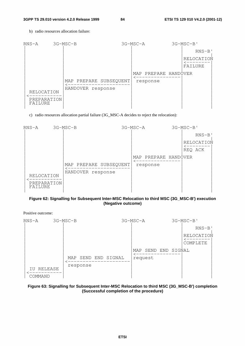
ETSI
ETSI TS 129 010 V4.2.0 (2001-12)843GPP TS 29.010 version 4.2.0 Release 1999
b) radio resources allocation failure:
RNS-A 3G-MSC-B 3G-MSC-A 3G-MSC-B' | | | | | | | | RNS-B' | | | | | | | | |RELOCATION | | | |<--------| | | | |FAILURE | | | | | | | | |MAP PREPARE HANDOVER | | | |<---------------| | | |MAP PREPARE SUBSEQUENT| response | | | |<---------------------| | | | |HANDOVER response | | | | RELOCATION | | | | |<-----------| | | | | PREPARATION| | | | | FAILURE | | | | | | | | |
c) radio resources allocation partial failure (3G_MSC-A decides to reject the relocation):
RNS-A 3G-MSC-B 3G-MSC-A 3G-MSC-B' | | | | | | | | RNS-B' | | | | | | | | |RELOCATION | | | |<--------| | | | |REQ ACK | | | | | | | | |MAP PREPARE HANDOVER | | | |<---------------| | | |MAP PREPARE SUBSEQUENT| response | | | |<---------------------| | | | |HANDOVER response | | | | RELOCATION | | | | |<-----------| | | | | PREPARATION| | | | | FAILURE | | | | | | | | |
Figure 62: Signalling for Subsequent Inter-MSC Relocation to third MSC (3G_MSC-B') execution
(Negative outcome)
Positive outcome:
RNS-A 3G-MSC-B 3G-MSC-A 3G-MSC-B' | | | | | | | | RNS-B' | | | | | | | | |RELOCATION | | | |<--------| | | | |COMPLETE | | | | | | | | |MAP SEND END SIGNAL | | | |<---------------| | | | MAP SEND END SIGNAL |request | | | |<---------------------| | | | | response | | | | IU RELEASE | | | | |<-----------| | | | | COMMAND | | | |
Figure 63: Signalling for Subsequent Inter-MSC Relocation to third MSC (3G_MSC-B') completion
(Successful completion of the procedure)

ETSI
ETSI TS 129 010 V4.2.0 (2001-12)853GPP TS 29.010 version 4.2.0 Release 1999
Negative outcome:
RNS-A 3G-MSC-B 3G-MSC-A 3G-MSC-B' | | | | |RELOCATION | | | RNS-B' |----------->| | | | |CANCEL |MAP PROCESS ACCESS | | | | |--------------------->| | | | |SIGNALLING request (Note 1) | | | | | | | | | |MAP U -ABORT | | | | |--------------->| | | |MAP FORWARD ACCESS | |IU RELEASE | |<---------------------| |-------->| |RELOCATION | SIGNALLING request | |COMMAND | |<-----------| | | | |CANCEL ACK | | | | | | | | |
Figure 64: Signalling for Subsequent Inter-MSC Relocation to third MSC (3G_MSC-B') completion
(Unsuccessful completion of the procedure)
NOTE: Specific interworking case detailed below.
The specific interworking case in 3G_MSC-A compared to the subclauses 4.8.1 and 4.8.2 occurs between RELOCATION FAILURE encapsulated in a Process Access Signalling from 3G_MSC-B and the abortion of the dialogue with 3G_MSC-B' in the case of relocation cancelled:
---------------------------------------------------------------- | 29.002 29.002 |Notes --------┼-------------------------------------------------┼----- Forward | MAP PROCESS-SIGNALLING | message | request | | | | -an-APDU( MAP U -ABORT | 1 | RELOCATION CANCEL) | | | --------┼-------------------------------------------------┼----- Positive| MAP FORWARD-SIGNALLING | result | request | | -an-APDU( | | RELOCATION CANCEL ACK) | --------┼-------------------------------------------------┼----- Negative| | result | MAP U/P -ABORT | 2 | |
NOTE 1: The abortion of the dialogue triggers in 3G_MSC-B' the clearing of the circuit connection with 3G_MSC-
A, if any, and of the Resources between 3G_MSC-B' and RNS-B'. The abortion of the dialogue ends the relocation procedure with 3G_MSC-B'.
NOTE 2: The abortion of the dialogue ends the relocation procedure with 3G_MSC-B.
4.8.4 RANAP Messages transfer on E-Interface
The following mapping applies to the encapsulation performed in 3G_MSC-A.

ETSI
ETSI TS 129 010 V4.2.0 (2001-12)863GPP TS 29.010 version 4.2.0 Release 1999
---------------------------------------------------------------- | 25.413 29.002 |Notes --------┼-------------------------------------------------┼----- Forward | RANAP messages MAP FORWARD ACCESS SIGNALLING| message | request | 1 | | | -an-APDU (RANAP messages) | --------┼-------------------------------------------------┼----- Positive| | result | | 2 --------┼-------------------------------------------------┼----- Negative| | result | MAP CLOSE | | MAP U/P -ABORT | | |
NOTE 1: Complete RANAP messages to be sent on 3G_MSC-B - RNS-B interface are embedded into the an-
APDU parameter.
NOTE 2: The Return Result does not apply. If 3G_MSC-B returns a message, this message will arrive in an Invoke: Process Access Signalling.
The following mapping applies to the encapsulation performed in 3G_MSC-B.
---------------------------------------------------------------- | 25.413 29.002 |Notes --------┼-------------------------------------------------┼----- Forward | RANAP messages MAP PROCESS ACCESS SIGNALLING| message | request | 1 | | | -an-APDU (RANAP messages) | --------┼-------------------------------------------------┼----- Positive| | result | | 2 --------┼-------------------------------------------------┼----- Negative| | result | MAP CLOSE | | IU RELEASE COMMAND | | | | Unspecified failure MAP U/P -ABORT | 3 | |
NOTE 1: Complete RANAP messages to be sent to 3G_MSC-A are embedded into the an-APDU parameter.
NOTE 2: The Return Result does not apply. If 3G_MSC-A returns a message, this message will arrive in an Invoke: Forward Access Signalling.
NOTE 3: The abortion of the dialogue triggers the clearing of the circuit connection with 3G_MSC-A, if any, of the Radio Resources on the Iu-Interface and the release of the SCCP connection between 3G_MSC-B and RNS-B. The clearing of the Radio Resources (the clearing indication received from RNS-B is transmitted to 3G_MSC-A) or the loss of the SCCP connection between 3G_MSC-B and RNS-B, triggers in 3G_MSC-B the abortion of the dialogue on the E-Interface and the clearing of the circuit connection with 3G_MSC-A, if any.
4.8.5 Processing in 3G_MSC-B, and information transfer on E-interface
The following parameters require processing (e.g. to store the parameter, to internally generate the parameter) in 3G_MSC-B. The relevant RANAP procedures are mentioned to ease the comprehension, their detailed description is the scope of the TS 25.413. Each RANAP message being transferred on E-interface shall use the mechanisms given in subclause 4.8.4 and is described in TS 25.413.
4.8.5.1 Integrity Protection Information
A sequence of possible integrity protection algorithms can be sent to an RNS in Security Mode Command or Relocation Request. The RNS chooses one of the listed algorithms and reports this back to the 3G_MSC in Security Mode Complete or Relocation Request Acknowledge respectively.
The list of algorithms, the integrity protection key and the chosen algorithm shall be stored by 3G_MSC-B.

ETSI
ETSI TS 129 010 V4.2.0 (2001-12)873GPP TS 29.010 version 4.2.0 Release 1999
Transfer of Information:
If integrity protection has not been performed before Inter-MSC Relocation, this will be controlled by 3G_MSC-A after the completion of Inter-MSC Relocation.
Integrity protection control towards 3G_MSC-B:
If Integrity protection has been performed before Inter-MSC Relocation:
- in the Relocation Request RANAP message (information included).
The Relocation Request Acknowledge should in this case contain the indication of the chosen algorithm.
If Integrity protection has NOT been performed before Inter-MSC Relocation:
- in the Security Mode Command procedure between 3G_MSC-A and 3G_MSC-B.
4.8.5.2 Encryption Information
A sequence of possible encryption algorithms can be sent to an RNS in Security Mode Command or Relocation Request. The RNS chooses one of the listed algorithms and reports this back to the 3G_MSC in Security Mode Complete or Relocation Request Acknowledge respectively.
The list of algorithms, the ciphering key and the chosen algorithm shall be stored by 3G_MSC-B, and the chosen value sent to 3G_MSC-A.
Transfer of Information:
If ciphering has not been performed before Inter-MSC Relocation, this will be controlled by 3G_MSC-A after the completion of Inter-MSC Relocation.
Ciphering control towards 3G_MSC-B:
If Ciphering has been performed before Inter-MSC Relocation:
- in the Relocation Request RANAP message (information included).
The Relocation Request Acknowledge should in this case contain the indication of the chosen algorithm.
If Ciphering has NOT been performed before Inter-MSC Relocation:
- in the Security Mode Command procedure between 3G_MSC-A and 3G_MSC-B.
4.8.5.3 RAB Parameters
The parameters shall be stored by 3G_MSC-B to be used at internal Relocation in 3G_MSC-B.
Transfer of information:
Received by 3G_MSC-B from 3G_MSC-A in:
− The Relocation Request RANAP message.
If a new type of resource is to be assigned after Inter-MSC Relocation, this can be made with:
− The RAB Assignment Request RANAP message.
4.8.5.4 Channel Type
Channel Type is GSM information that is required in BSSMAP Handover Request and BSSMAP Assignment Request, and it shall be provided by 3G_MSC-A. 3G_MSC-B needs this information in case of an intra-MSC UMTS to GSM handover after an inter-MSC relocation and subsequent assignment procedures. The Channel Type derived from the Bearer Capability that is available in 3G_MSC-A. This mapping is described in 3GPP TS 27.001. Therefore 3G_MSC-A must provide this information in case of an inter-MSC relocation. The Radio Resource Information IE in the MAP Prepare Handover message refers to the Channel Type GSM information.
ETSI
ETSI TS 129 010 V4.2.0 (2001-12)883GPP TS 29.010 version 4.2.0 Release 1999
Channel Type shall be stored by 3G_MSC-B.
Transfer of information:
Received by 3G_MSC-B from 3G_MSC-A in:
− The Prepare Handover Request MAP message.
− The Forward Access Signalling Request message.
4.8.5.5 Selected GSM Algorithm
After inter-MSC relocation, the 3G_MSC-B can perform intra-MSC UMTS to GSM handover. A sequence of possible encryption algorithms, received from the 3G_MSC-A, can be sent to an BSS in Handover Request or in Cipher Mode Command in case of cipher mode setting after intra.MSC-B handover from UMTS to GSM. The BSS chooses one of the listed algorithms and reports this back to the 3G_MSC in Handover Request Acknowledge or Cipher Mode Complete respectively. The MSC-B provides the Selected GSM algorithm information to the MSC-A. The Selected GSM algorithms IE in the MAP Process Access Signalling Request message refers to the Algorithm identifier octet in the Chosen Encryption Algorithm GSM information.
The chosen algorithm shall be stored by 3G_MSC-B, and sent to 3G_MSC-A.
Transfer of Information:
If ciphering has not been performed before Inter-MSC Relocation, this will be controlled by 3G_MSC-A after the completion of Inter-MSC Relocation.
If Ciphering has been performed before Inter-MSC Relocation, Selected GSM algorithm information is received by 3G_MSC-A from 3G_MSC-B in:
− The Handover Performed BSSMAP message.
If Ciphering has NOT been performed before Intra-MSC-B handover from UMTS to GSM after Inter-MSC Relocation, Selected GSM algorithm information is received by 3G_MSC-A from 3G_MSC-B in:
− The Process Access Signalling Request MAP message.
4.8.5.6 Allowed GSM Algorithms
Allowed GSM algorithms is GSM information that is required in BSSMAP Handover Request and BSSMAP Cipher Mode Command, and shall be provided by 3G_MSC-A. 3G_MSC-B needs this information in case of an intra-MSC UMTS to GSM handover and in subsequent ciphering mode setting, after an inter-MSC relocation. Therefore 3G_MSC-A must provide this information in case of an inter-MSC relocation. The Allowed GSM algorithms IE in the MAP Prepare Handover and in the MAP Forward Access Signalling Request messages refers to the Algorithm identifier octet in the Permitted Algorithms GSM information.
Allowed GSM algorithms shall be stored by 3G_MSC-B.
Transfer of information:
If ciphering has not been performed before Inter-MSC Relocation, this will be controlled by 3G_MSC-A after the completion of Inter-MSC Relocation.
Ciphering control towards 3G_MSC-B:
If Ciphering has been performed before Inter-MSC Relocation:
− The Prepare Handover Request MAP message.
If Ciphering has NOT been performed before Inter-MSC Relocation:

ETSI
ETSI TS 129 010 V4.2.0 (2001-12)893GPP TS 29.010 version 4.2.0 Release 1999
− The Forward Access Signalling Request MAP message.
4.8.5.7 Chosen Channel
BSSMAP Assignment Request may give the BSS some freedom in the selection of radio resource (for instance channel rate selection, speech version selection etc.). Chosen Channel and/or Speech Version is reported back to 3G_MSC-B in BSSMAP Assignment Complete. The Chosen Radio Resource Information IE in the MAP Prepare Handover Response and Process Access Signalling Request messages refers to the Chosen Channel and/or Speech Version GSM information.
The Channel Type and the characteristics of the chosen channel shall be stored by 3G_MSC-B, and the Chosen Channel and/or Speech Version information elements shall be transferred to MSC-A or 3G_MSC-A.
Transfer of information:
Received by MSC-A or 3G_MSC-A from 3G_MSC-B in:
− The Prepare Handover Response MAP message
− The Process Access Signalling request MAP message
4.8.6 Overview of the Technical Specifications 3GPP interworking for the Inter-MSC Relocation

ETSI
ETSI TS 129 010 V4.2.0 (2001-12)903GPP TS 29.010 version 4.2.0 Release 1999
╔══════════════════════════════════════════════════════════════════════════════════════════════════╗ ║ PSTN/ISDN ║ ║ ▒▒▒▒▒▒▒▒▒▒▒▒▒▒▒▒▒▒▒▒▒▒▒▒▒▒▒▒▒▒▒▒▒▒▒▒▒▒▒▒▒▒▒▒▒▒▒▒▒▒ ║ ║ ▒ +---------------+ ▒ ║ ║ ==============▒====== | ============= | =============== ▒ ║ ║ UMTS ▒ | | ▒ ║ ║ ▒ V V ▒ ║ ║ ▒▒▒▒▒▒▒▒▒▒▒▒▒▒▒ ▒ ║ ║ ▒ RNS-A 3G-MSC-A 3G-MSC-B RNS-B ▒ MS ║ ║ ▒ ▒ ║ ║ ▒ +-------+ ▒ +-------+ ║ ║ ▒ | C M | 24.008 ▒ | C M | ║ ║ ▒ +-------|<------------------------------------>+-------| ║ ║ ▒ ░░░░░░░░░░░░░░░ | M M | ░░░░░░░░░░░░░░░░░░░░░░░░░░░░░░░░░░▒ | M M | ║ ║ ▒ ░+------+25.413 +-------| 25.413+-------+ 25.413+-------+ ░▒ +-------| ║ ║ ▒ ░| R R |<----->| R R |<=====>| R R |<----->| R R | ░▒ | R R | ║ ║ ▒ ░+------+ +-------+ +-------+ +-------+ ░▒ +-------+ ║ ║ ▒ ░ Λ Λ Λ Λ ░▒ ║ ║ ▒ ░ | | 29.010 | | ░▒ ║ ║ ▒ ░ | V V | ░▒ ║ ║ ▒ ░ |+-----+ 29.002+-----+| ░▒ ║ ║ ▒ ░ ||MAP/E|<----->|MAP/E|| ░▒ ║ ║ ▒ ░ |+-----+ +-----+| 23.009░▒ ║ ║ ▒ ░░░░░░░░░░░░░░░░ | ░░░░░░░░░░░░░░░░░░░ | ░░░░░░░░░░░░░░░░░░░▒ Remark: The RRC interface and ║ ║ ▒▒▒▒▒▒▒▒▒▒▒▒▒▒▒▒▒▒ V ▒▒▒▒▒▒▒▒▒▒▒▒▒▒▒▒▒▒▒ V ▒▒▒▒▒▒▒▒▒▒▒▒▒▒▒▒▒▒▒▒ the link layer ║ ║ +-----------------------+ protocols being out of ║ ║ | T C A P | the scope of this ║ ║ +-----------------------+ Specification are not ║ ║ +------------------------------------------------------+ shown here. ║ ║ | S C C P | ║ ║ +------------------------------------------------------+ ║ ║ +------------------------------------------------------+ ║ ║ | M T P | ║ ║ +------------------------------------------------------+ ║ ╚══════════════════════════════════════════════════════════════════════════════════════════════════╝

ETSI
ETSI TS 129 010 V4.2.0 (2001-12)913GPP TS 29.010 version 4.2.0 Release 1999
4.9 4.9 Location Services The general principles of the location services procedures are given in Technical Specification 3GPP TS 23.271.
3GPP TS 29.010 gives the necessary information for interworking between the 3GPP TS 25.413 RANAP protocol and the 3GPP TS 48.008 BSSMAP protocol. The interworking is necessary for positioning requests issued after a completed GSM to UMTS inter system handover. BSSMAP messages carried by MAP over the E-interface must be mapped by the non-anchor 3G-MSC into the corresponding RANAP messages to be sent over the Iu-interface and vice versa. In case of Inter-MSC GSM to GSM Handover and Inter-MSC UMTS to UMTS SRNS Relocation no mapping between the 3GPP TS 25.413 RANAP protocol and the GSM 08.08 BSSMAP protocol is necessary, but only the interworking with the MAP protocol over the E-interface needs to be described.
4.9.1 Completed Location Acquisition
4.9.1.1 Inter-MSC Handover (GSM to GSM)
After a successful Inter-MSC handover, any positioning request received by the anchor MSC via the MAP message Provide Subscriber Location triggers the BSSMAP procedure Location Acquisition described in GSM 08.08. In case of handover this procedure is executed according to GSM 09.08 with the anchor MSC playing the role of the MSC and the non anchor MSC playing the role of the BSS.
The needed BSSMAP signalling is sent over the E-interface encapsulated in the MAP messages Process Access Signalling and Forward Access Signalling.
At the non anchor MSC the received BSSMAP messages are forwarded to the BSS, and the received BSSMAP messages are sent over the E-interface to the anchor MSC.
The signalling for a completed Location Acquisition procedure is shown in figures 65a.

ETSI
ETSI TS 129 010 V4.2.0 (2001-12)923GPP TS 29.010 version 4.2.0 Release 1999
GMLC MSC-A MSC-B | | | |MAP PROVIDE | | |SUBSCRIBER | | |LOCATION | | |-------------->|MAP FORWARD ACCESS | | | SIGNALLING | | |------------------------>| | | -an-APDU( | | | PERFORM LOCATION | | | REQUEST) | | | | | | | BSS-B | | | | | | | | | | |------------------>| | | | | | | | PERFORM LOCATION | | | | REQUEST | | | | | | | | | | | | +-----------+ | | | |Positioning| | | | | is | | | | | performed | | | | +-----------+ | | | | | | | | | | | | | | |<------------------| | | | | | | PERFORM LOCATION | | | RESPONSE | | | | | MAP PROCESS ACCESS | | | SIGNALLING | | |<------------------------| | | -an-APDU( | | | PERFORM LOCATION | | | RESPONSE) | |MAP PROVIDE | | |SUBSCRIBER | | |LOCATION res | | |<--------------| | | | |
Figure 65a: Signalling for a completed Location Acquisition procedure
4.9.1.2 Inter-MSC Handover (GSM to UMTS)
After a successful Inter-MSC GSM to UMTS inter system handover, any positioning request received by the anchor MSC via the MAP message Provide Subscriber Location triggers the BSSMAP procedure Location Acquisition described in 3GPP TS 48.008. In case of handover this procedure is executed according to 3GPP TS 49.008 with the anchor MSC playing the role of the MSC and the non anchor 3G MSC playing the role of the BSS.
The needed BSSMAP signalling is sent over the E-interface encapsulated in the MAP messages Process Access Signalling and Forward Access Signalling.
At the non anchor 3G MSC the received BSSMAP messages are mapped into the corresponding RANAP messages to be sent to the RNS, and the received RANAP messages are mapped into the corresponding BSSMAP messages to be sent over the E-interface to the anchor MSC.
The signalling for a completed Location Acquisition procedure is shown in figures 65.

ETSI
ETSI TS 129 010 V4.2.0 (2001-12)933GPP TS 29.010 version 4.2.0 Release 1999
GMLC MSC-A 3G-MSC-B | | | |MAP PROVIDE | | |SUBSCRIBER | | |LOCATION | | |-------------->|MAP FORWARD ACCESS | | | SIGNALLING | | |------------------------>| | | -an-APDU( | | | PERFORM LOCATION | | | REQUEST) | | | | | | | RNS-B | | | | | | |LOCATION REPORTING | | | | CONTROL | | | |------------------>| | | | | | | | +-----------+ | | | |Positioning| | | | | is | | | | | performed | | | | +-----------+ | | | | | | |LOCATION REPORT | | | |<------------------| | |MAP PROCESS ACCESS | | | SIGNALLING | | |<------------------------| | | -an-APDU( | | | PERFORM LOCATION | | | RESPONSE) | |MAP PROVIDE | | |SUBSCRIBER | | |LOCATION res | | |<--------------| | | | |
Figure 65: Signalling for a completed Location Acquisition procedure
The interworking between the BSSMAP location aquisition messages in MAP and the RANAP location reporting messages is as follows:

ETSI
ETSI TS 129 010 V4.2.0 (2001-12)943GPP TS 29.010 version 4.2.0 Release 1999
---------------------------------------------------------------- | 29.002 25.413 |Notes --------┼-------------------------------------------------┼----- Forward | MAP FORWARD ACCESS SIG. LOCATION REPORTING | message | request CONTROL | | | | -an-APDU( | | PERFORM LOCATION REQUEST) | | | | BSSMAP information RANAP information | | elements: elements: | | | | Location Type Request Type | 1 | >Current Geographic >Event = Direct | | Location >Report Area = | | Geo. Coord. | | | | Cell Identifier ---- | | Classmark Inf. Type3 ---- | | LCS Client Type ---- | | Chosen Channel ---- | | LCS Priority ---- | | LCS QoS Request Type | | >Accuracy Code | | | | GPS Assistance Data ---- | | APDU ---- | | | --------┼-------------------------------------------------┼----- Result | MAP PROCESS ACCESS SIG. LOCATION REPORT | | request | | -an-APDU( | | PERFORM LOCATION RESPONSE) | | | | BSSMAP information RANAP information | | elements: elements: | | | | | | Location Estimate Area Identity | | >Geographical Area | | Positioning Data ---- | | Deciphering Keys ---- | | LCS Cause Cause | | ---- Request Type | | | | | NOTE 1: All other Location Type possibilities are not supported by UMTS positioning
4.9.1.3 Inter-MSC Handover (UMTS to GSM)
After a successful Inter-MSC UMTS to GSM inter system handover, any positioning request received by the anchor 3G-MSC via the MAP message Provide Subscriber Location triggers the BSSMAP procedure Location Acquisition described in GSM 08.08. In case of handover this procedure is executed according to GSM 09.08 with the anchor 3G-MSC playing the role of the 3G-MSC and the non anchor MSC playing the role of the BSS.
The needed BSSMAP signalling is sent over the E-interface encapsulated in the MAP messages Process Access Signalling and Forward Access Signalling.
At the non anchor MSC the received BSSMAP messages are forwarded to the BSS, and the received BSSMAP messages are sent over the E-interface to the anchor 3G-MSC.
The signalling for a completed Location Acquisition procedure is shown in figures 65b.

ETSI
ETSI TS 129 010 V4.2.0 (2001-12)953GPP TS 29.010 version 4.2.0 Release 1999
GMLC 3G-MSC-A MSC-B | | | |MAP PROVIDE | | |SUBSCRIBER | | |LOCATION | | |-------------->|MAP FORWARD ACCESS | | | SIGNALLING | | |------------------------>| | | -an-APDU( | | | PERFORM LOCATION | | | REQUEST) | | | | | | | BSS-B | | | | | | | | | | |------------------>| | | | | | | | PERFORM LOCATION | | | | REQUEST | | | | | | | | | | | | +-----------+ | | | |Positioning| | | | | is | | | | | performed | | | | +-----------+ | | | | | | | | | | | | | | |<------------------| | | | | | | PERFORM LOCATION | | | RESPONSE | | | | | MAP PROCESS ACCESS | | | SIGNALLING | | |<------------------------| | | -an-APDU( | | | PERFORM LOCATION | | | RESPONSE) | |MAP PROVIDE | | |SUBSCRIBER | | |LOCATION res | | |<--------------| | | | |
Figure 65b: Signalling for a completed Location Acquisition procedure
4.9.1.4 Inter-MSC SRNS Relocation
After a successful Inter-MSC SRNS Relocation, any positioning request received by the anchor 3G-MSC via the MAP message Provide Subscriber Location triggers the RANAP procedure Location Reporting Control described in TS 25.413. In case of handover this procedure is executed according to 23.009 with the anchor 3G-MSC playing the role of the 3G-MSC and the non anchor 3G-MSC playing the role of the RNS.
The needed RANAP signalling is sent over the E-interface encapsulated in the MAP messages Process Access Signalling and Forward Access Signalling.
At the non anchor 3G-MSC the received RANAP messages are forwarded to the RNS, and the received RANAPmessages are sent over the E-interface to the anchor 3G-MSC.
The signalling for a completed Location Acquisition procedure is shown in figures 65c.

ETSI
ETSI TS 129 010 V4.2.0 (2001-12)963GPP TS 29.010 version 4.2.0 Release 1999
GMLC 3G-MSC-A 3G-MSC-B | | | |MAP PROVIDE | | |SUBSCRIBER | | |LOCATION | | |-------------->|MAP FORWARD ACCESS | | | SIGNALLING | | |------------------------>| | | -an-APDU( | | | LOCATION REPORTING | | | CONTROL) | | | | | | | RNS-B | | | | | | | | | | |------------------>| | | | | | | |LOCATION REPORTING | | | | CONTROL | | | | | | | | | | | | +-----------+ | | | |Positioning| | | | | is | | | | | performed | | | | +-----------+ | | | | | | | | | | | | | | |<------------------| | | | | | |LOCATION REPORT | | | | | | | | MAP PROCESS ACCESS | | | SIGNALLING | | |<------------------------| | | -an-APDU( | | | LOCATION REPORT) | | | | |MAP PROVIDE | | |SUBSCRIBER | | |LOCATION res | | |<--------------| | | | |
Figure 65c: Signalling for a completed Location Acquisition procedure
4.9.1 Cause Code Mapping
4.9.2.1 Inter-MSC Handover (GSM to GSM)
When a mobile station is handed over from GSM to GSM, no mapping of cause codes is required. The MSC shall use the cause codes specified in GSM 08.08.
4.9.2.2 Inter-MSC Handover (GSM to UMTS)
When a Mobile Station is handed over between GSM and UMTS, a mapping of the cause codes used in the RANAP and the BSSMAP protocols is needed. The mapping described here is applicable to the BSSMAP protocol even when used inside MAP in the E-interface.
The mapping between the cause codes received in RANAP Location Report and the LCS cause codes sent in BSSMAP Perform Location Response is as follows:

ETSI
ETSI TS 129 010 V4.2.0 (2001-12)973GPP TS 29.010 version 4.2.0 Release 1999
---------------------------------------------------------------- 25.413 08.08 |Notes -------------------------------------------------------┼-------- LOCATION REPORT PERFORM LOCATION RESPONSE | | - Requested Report Type - Position method failure| not Supported | - Requested Information - System Failure | not Available | - all other cause codes - System Failure |
4.9.2.3 Inter-MSC Handover (UMTS to GSM)
When a mobile station is handed over from UMTS to GSM, no mapping of cause codes is required. The 3G-MSC shall use the cause codes specified in GSM 08.08.
4.9.2.4 Inter-MSC SRNS Relocation
When a mobile station is handed over from UMTS to UMTS, no mapping of cause codes is required. Both 3G-MSCs shall use the cause codes specified in TS 25.413.
4.9.3 Aborted Location Acquisition
4.9.3.1 Inter-MSC Handover (GSM to GSM)
When for any reason the on going location acquisition procedure needs to be aborted, the anchor MSC sends the BSSMAP message Perform Location Abort over the E-interface.
Figure 66a shows the signalling for an aborted Location Acquisition procedure.

ETSI
ETSI TS 129 010 V4.2.0 (2001-12)983GPP TS 29.010 version 4.2.0 Release 1999
GMLC MSC-A MSC-B | | | |MAP PROVIDE | | |SUBSCRIBER | | |LOCATION | | |-------------->|MAP FORWARD ACCESS | | | SIGNALLING | | |------------------------>| | | -an-APDU( | | | PERFORM LOCATION | | | REQUEST) | | | | | | | BSS-B | | | | | | | | | | | | | | |-------------------->| | | | | | | | PERFORM LOCATION | | | | REQUEST)| | | | | | | | | | |MAP FORWARD ACCESS | | | | SIGNALLING | | | |------------------------>| | | | -an-APDU( | | | | PERFORM LOCATION ABORT)| | | | | | | | | | | | | | | | | | | | |-------------------->| | | | | | | | PERFORM LOCATION | | | | ABORT | | | | | | |MAP PROCESS ACCESS | | | | SIGNALLING | | | |<------------------------| | | | -an-APDU( | | | | PERFORM LOCATION | | | | RESPONSE) | |
Figure 66a: Signalling for an aborted Location Acquisition procedure
4.9.3.2 Inter-MSC Handover (GSM to UMTS)
When for any reason the on going location acquisition procedure needs to be aborted, the anchor MSC sends the BSSMAP message Perform Location Abort over the E-interface.
Figure 66 shows the signalling for an aborted Location Acquisition procedure.

ETSI
ETSI TS 129 010 V4.2.0 (2001-12)993GPP TS 29.010 version 4.2.0 Release 1999
GMLC MSC-A 3G-MSC-B | | | |MAP PROVIDE | | |SUBSCRIBER | | |LOCATION | | |-------------->|MAP FORWARD ACCESS | | | SIGNALLING | | |------------------------>| | | -an-APDU( | | | PERFORM LOCATION | | | REQUEST) | | | | | | | RNS-B | | | | | | |LOCATION REPORTING | | | | CONTROL | | | |------------------>| | | | | | | | | | |MAP FORWARD ACCESS | | | | SIGNALLING | | | |------------------------>| | | | -an-APDU( | | | | PERFORM LOCATION ABORT)| | | | | | | | | | | | |LOCATION REPORTING | | | | CONTROL | | | |------------------>| | | | | | | | | | |MAP PROCESS ACCESS | | | | SIGNALLING | | | |<------------------------| | | | -an-APDU( | | | | PERFORM LOCATION | | | | RESPONSE) | |
Figure 66: Signalling for an aborted Location Acquisition procedure
The interworking between the BSSMAP location aquisition messages in MAP and the RANAP location reporting messages is as follows:
---------------------------------------------------------------- | 29.002 25.413 |Notes --------┼-------------------------------------------------┼----- Forward | MAP FORWARD ACCESS SIG. LOCATION REPORTING | message | request CONTROL | | | | -an-APDU( | | PERFORM LOCATION ABORT) | | | | BSSMAP information RANAP information | | elements: elements: | | | | LCS Cause Request Type | | >Event = Stop | | >Report Area = | | Geo. Coord. | | | | | --------┼-------------------------------------------------┼----- Result | MAP PROCESS ACCESS SIG. - | | request | 1 | -an-APDU( | | PERFORM LOCATION RESPONSE) | | | | BSSMAP information | | elements: | | | | ---- | | LCS Cause | | ---- | | |
NOTE 1: PERFORM LOCATION RESPONSE with LCS cause shall be generated by 3G-MSC-B.

ETSI
ETSI TS 129 010 V4.2.0 (2001-12)1003GPP TS 29.010 version 4.2.0 Release 1999
4.9.3.3 Inter-MSC Handover (UMTS to GSM)
When for any reason the on going location acquisition procedure needs to be aborted, the anchor 3G-MSC sends the BSSMAP message Perform Location Abort over the E-interface.
Figure 66b shows the signalling for an aborted Location Acquisition procedure.
GMLC 3G-MSC-A MSC-B | | | |MAP PROVIDE | | |SUBSCRIBER | | |LOCATION | | |-------------->|MAP FORWARD ACCESS | | | SIGNALLING | | |------------------------>| | | -an-APDU( | | | PERFORM LOCATION | | | REQUEST) | | | | | | | BSS-B | | | | | | | | | | | | | | |-------------------->| | | | | | | | PERFORM LOCATION | | | | REQUEST)| | | | | | | | | | |MAP FORWARD ACCESS | | | | SIGNALLING | | | |------------------------>| | | | -an-APDU( | | | | PERFORM LOCATION ABORT)| | | | | | | | | | | | | | | | | | | | |-------------------->| | | | | | | | PERFORM LOCATION | | | | ABORT | | | | | | |MAP PROCESS ACCESS | | | | SIGNALLING | | | |<------------------------| | | | -an-APDU( | | | | PERFORM LOCATION | | | | RESPONSE) | |
Figure 66b: Signalling for an aborted Location Acquisition procedure
4.9.3.4 Inter-MSC SRNS Relocation
When for any reason the on going location acquisition procedure needs to be aborted, the anchor 3G-MSC sends the RANAP message Location Reporting Control over the E-interface.
Figure 66c shows the signalling for an aborted Location Acquisition procedure.
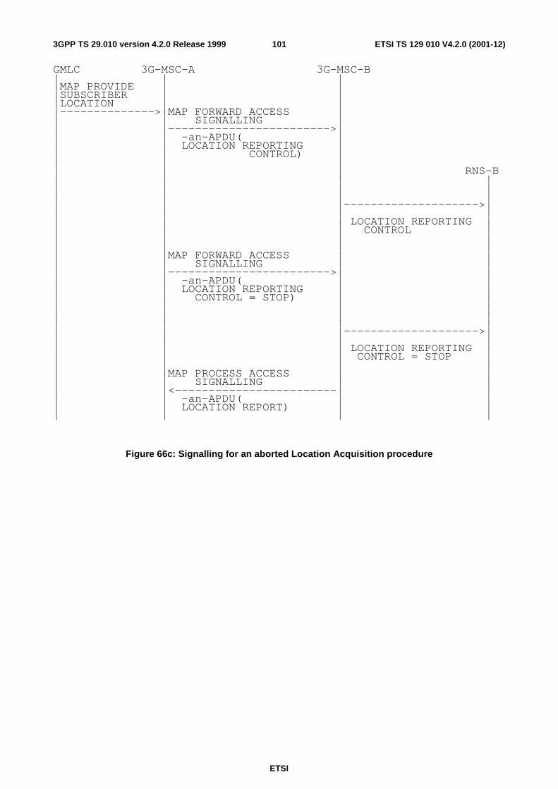
ETSI
ETSI TS 129 010 V4.2.0 (2001-12)1013GPP TS 29.010 version 4.2.0 Release 1999
GMLC 3G-MSC-A 3G-MSC-B | | | |MAP PROVIDE | | |SUBSCRIBER | | |LOCATION | | |-------------->|MAP FORWARD ACCESS | | | SIGNALLING | | |------------------------>| | | -an-APDU( | | | LOCATION REPORTING | | | CONTROL) | | | | | | | RNS-B | | | | | | | | | | | | | | |-------------------->| | | | | | | | LOCATION REPORTING | | | | CONTROL | | | | | | | | | | |MAP FORWARD ACCESS | | | | SIGNALLING | | | |------------------------>| | | | -an-APDU( | | | | LOCATION REPORTING | | | | CONTROL = STOP) | | | | | | | | | | | | | | | | |-------------------->| | | | | | | | LOCATION REPORTING | | | | CONTROL = STOP | | | | | | |MAP PROCESS ACCESS | | | | SIGNALLING | | | |<------------------------| | | | -an-APDU( | | | | LOCATION REPORT) | | | | | |
Figure 66c: Signalling for an aborted Location Acquisition procedure

ETSI
ETSI TS 129 010 V4.2.0 (2001-12)1023GPP TS 29.010 version 4.2.0 Release 1999
Annex A (informative): Change history
Change history TSG CN# Spec Version CR <Phase> New Version Subject/Comment Sept 1999 GSM 09.10 7.0.0 Transferred to 3GPP CN CN#04 29.010 R99 3.0.0 Approved by mail exploder at CN#04 CN#06 29.010 3.0.0 001 R99 3.1.0 UMTS / GSM Interworking CN#06 29.010 3.0.0 002 R99 3.1.0 Addition of LSA Information message CN#07 29.010 3.1.0 003r1 R99 3.2.0 UMTS / GSM Interworking CN#07 29.010 3.1.0 004r1 R99 3.2.0 GSM / UMTS Interworking CN#07 29.010 3.1.0 005 R99 3.2.0 UMTS/UMTS Handover CN#09 29.010 3.2.0 006r1 R99 3.3.0 Clarification of use of Radio Resource
Information CN#09 29.010 3.2.0 007r1 R99 3.3.0 Corrections and updates to align with current
R99 specs CN#10 29.010 3.3.0 008 R99 3.4.0 GSM to 3G Handover: Location Reporting in
3G_MSC-B CN#10 29.010 3.3.0 009 R99 3.4.0 GSM to 3G Handover: Chosen IEs in
Handover Request Ack CN#10 29.010 3.3.0 010 R99 3.4.0 GSM to 3G Handover: MAP parameter Target
Cell ID CN#10 29.010 3.3.0 011r1 R99 3.4.0 GSM/UMTS Interworking: Mapping of cause
codes CN#11 29.010 3.4.0 012 R99 3.5.0 GSM to UMTS handover: addition of MAP
parameter Target RNC ID CN#11 29.010 3.4.0 013 R99 3.5.0 Inter MSC relocation: addition of MAP
parameter Target RNC ID CN#11 29.010 3.4.0 014 R99 3.5.0 Roaming restrictions for GPRS service CN#11 29.010 3.4.0 015 R99 3.5.0 Alignment of cause mapping for 08.08 and
25.413 (Directed Retry) CN#11 29.010 3.4.0 016 R99 3.5.0 UMTS to GSM Directed Retry cause code
mapping CN#11 29.010 3.4.0 017 R99 3.5.0 Mapping of unknown HLR error to access
interface cause code CN#11 29.010 3.5.0 Rel-4 4.0.0 Version increased from R99 to Rel-4 CN#12 29.010 4.0.0 020r1 Rel-4 4.1.0 Addition of selected UMTS algorithm
indication to the handover procedures CN#12 29.010 4.0.0 022r1 Rel-4 4.1.0 Addition of selected GSM algorithm indication
to the handover procedures CN#12 29.010 4.0.0 024r1 Rel-4 4.1.0 Addition of allowed UMTS algorithms
indication to the handover procedures CN#12 29.010 4.0.0 026r1 Rel-4 4.1.0 Addition of allowed GSM algorithms indication
to the handover procedures CN#12 29.010 4.0.0 028r1 Rel-4 4.1.0 Addition of GSM channel type and GSM
chosen channel indications to handover procedures
CN#12 29.010 4.0.0 030 Rel-4 4.1.0 Partial Roaming – restriction by Location area CN#12 29.010 4.0.0 031 Rel-4 4.1.0 Mapping between RANAP and BSSMAP for
Location Services CN#12 29.010 4.0.0 034r1 Rel-4 4.1.0 Mapping between RANAP and BSSMAP for
Location Services CN#14 29.010 4.1.0 036r2 Rel-4 4.2.0 LCS/HO Location Reporting – GSM to GSM,
UMTS to GSM and UMTS to UMTS CN#14 29.010 4.1.0 040 Rel-4 4.2.0 Global replace of BSS-APDU with AN-APDU CN#14 29.010 4.1.0 047 Rel-4 4.2.0 Removal of deleted MAP operations

ETSI
ETSI TS 129 010 V4.2.0 (2001-12)1033GPP TS 29.010 version 4.2.0 Release 1999
History
Document history
V4.0.0 March 2001 Publication
V4.1.0 June 2001 Publication
V4.2.0 December 2001 Publication


![TR 182 030 - V3.1.1 - Telecommunications and Internet ... 7 ETSI TR 182 030 V3.1.1 (2011-05) [i.26] ETSI TS 182 019: "Telecommunications and Internet converged Services and Protocols](https://static.fdocuments.net/doc/165x107/5b2ec97d7f8b9ac06e8cc8d2/tr-182-030-v311-telecommunications-and-internet-7-etsi-tr-182-030-v311.jpg)