
TS 125 430 - V3.4.0 - Universal Mobile Telecommunications ... · ETSI 3GPP TS 25.430 version 3.4.0...
25
ETSI TS 125 430 V3.4.0 (2000-12) Technical Specification Universal Mobile Telecommunications System (UMTS); UTRAN l ub Interface: General Aspects and Principles (3GPP TS 25.430 version 3.4.0 Release 1999)
Transcript of TS 125 430 - V3.4.0 - Universal Mobile Telecommunications ... · ETSI 3GPP TS 25.430 version 3.4.0...
ETSI TS 125 430 V3.4.0 (2000-12)Technical Specification
Universal Mobile Telecommunications System (UMTS);UTRAN lub Interface: General Aspects and Principles
(3GPP TS 25.430 version 3.4.0 Release 1999)
1
ETSI
ETSI TS 125 430 V3.4.0 (2000-12)3GPP TS 25.430 version 3.4.0 Release 1999
ReferenceRTS/TSGR-0325430UR4
KeywordsUMTS
ETSI
650 Route des LuciolesF-06921 Sophia Antipolis Cedex - FRANCE
Tel.: +33 4 92 94 42 00 Fax: +33 4 93 65 47 16
Siret N° 348 623 562 00017 - NAF 742 CAssociation à but non lucratif enregistrée à laSous-Préfecture de Grasse (06) N° 7803/88
Important notice
Individual copies of the present document can be downloaded from:http://www.etsi.org
The present document may be made available in more than one electronic version or in print. In any case of existing orperceived difference in contents between such versions, the reference version is the Portable Document Format (PDF).
In case of dispute, the reference shall be the printing on ETSI printers of the PDF version kept on a specific network drivewithin ETSI Secretariat.
Users of the present document should be aware that the document may be subject to revision or change of status.Information on the current status of this and other ETSI documents is available at http://www.etsi.org/tb/status/
If you find errors in the present document, send your comment to:[email protected]
Copyright Notification
No part may be reproduced except as authorized by written permission.The copyright and the foregoing restriction extend to reproduction in all media.
© European Telecommunications Standards Institute 2000.
All rights reserved.
2
ETSI
ETSI TS 125 430 V3.4.0 (2000-12)3GPP TS 25.430 version 3.4.0 Release 1999
Intellectual Property RightsIPRs essential or potentially essential to the present document may have been declared to ETSI. The informationpertaining to these essential IPRs, if any, is publicly available for ETSI members and non-members, and can be foundin ETSI SR 000 314: "Intellectual Property Rights (IPRs); Essential, or potentially Essential, IPRs notified to ETSI inrespect of ETSI standards", which is available from the ETSI Secretariat. Latest updates are available on the ETSI Webserver (http://www.etsi.org/ipr).
Pursuant to the ETSI IPR Policy, no investigation, including IPR searches, has been carried out by ETSI. No guaranteecan be given as to the existence of other IPRs not referenced in ETSI SR 000 314 (or the updates on the ETSI Webserver) which are, or may be, or may become, essential to the present document.
ForewordThis Technical Specification (TS) has been produced by the ETSI 3rd Generation Partnership Project (3GPP).
The present document may refer to technical specifications or reports using their 3GPP identities, UMTS identities orGSM identities. These should be interpreted as being references to the corresponding ETSI deliverables.
The cross reference between GSM, UMTS, 3GPP and ETSI identities can be found under www.etsi.org/key .
ETSI
ETSI TS 125 430 V3.4.0 (2000-12)33GPP TS 25.430 version 3.4.0 Release 1999
Contents
Foreword.............................................................................................................................................................5
1 Scope ........................................................................................................................................................6
2 References ................................................................................................................................................6
3 Definitions and abbreviations...................................................................................................................63.1 Definitions..........................................................................................................................................................63.2 Abbreviations .....................................................................................................................................................7
4 General Aspects........................................................................................................................................84.1 Introduction ........................................................................................................................................................84.2 Iub Interface General Principles.........................................................................................................................84.3 Iub Interface Specification Objectives ...............................................................................................................84.4 Iub Interface Capabilities ...................................................................................................................................94.4.1 Radio application related signalling..............................................................................................................94.4.2 Iub/Iur DCH data stream...............................................................................................................................94.4.3 Iub RACH data stream..................................................................................................................................94.4.4 Iub FDD CPCH data stream .........................................................................................................................94.4.5 Iub FACH data stream ..................................................................................................................................94.4.6 Iub DSCH data stream ..................................................................................................................................94.4.7 Iub TDD USCH data stream.........................................................................................................................94.4.8 Iub PCH data stream.....................................................................................................................................94.5 Iub Interface Characteristics.............................................................................................................................104.5.1 Mapping of Iub data streams.......................................................................................................................104.6 Iub Protocols ....................................................................................................................................................10
5 Functions of the Iub Interface Protocols..................................................................................................105.1 Iub Functions....................................................................................................................................................105.2 Functional split over Iub...................................................................................................................................125.2.1 Management of Iub Transport Resources ...................................................................................................125.2.2 Logical O&M of Node B ............................................................................................................................125.2.2.1 Handling of Node B Hardware Resources ............................................................................................125.2.3 Implementation Specific O&M Transport ..................................................................................................125.2.4 System Information Management...............................................................................................................125.2.5 Traffic management of Common Channels ................................................................................................125.2.6 Traffic management of Dedicated Channels...............................................................................................125.2.6.1 Combining/Splitting and Control ..........................................................................................................125.2.6.2 Handover Decision................................................................................................................................135.2.6.3 Allocation of Physical Channel Resources ...........................................................................................135.2.6.4 UpLink Power Control..........................................................................................................................135.2.6.5 Down-Link Power Control....................................................................................................................135.2.6.6 Admission Control ................................................................................................................................135.2.6.7 Power and Interference Reporting.........................................................................................................135.2.7 Traffic management of Shared Channels....................................................................................................145.2.8 Timing and Synchronization Management .................................................................................................14
6 Node B logical Model over Iub..............................................................................................................146.1 Overview..........................................................................................................................................................146.2 Elements of the logical model ..........................................................................................................................146.2.1 Node B Communication Contexts for Dedicated and Shared Channels .....................................................146.2.2 Common Transport Channels .....................................................................................................................156.2.3 Transport network logical resources ...........................................................................................................156.2.3.1 Node B Control Port .............................................................................................................................156.2.3.2 Communication Control Port ................................................................................................................166.2.3.3 Traffic Termination Point .....................................................................................................................166.2.3.4 Iub DCH Data Port................................................................................................................................166.2.3.5 Iub RACH Data Port .............................................................................................................................166.2.3.6 Iub FDD CPCH Data Port.....................................................................................................................16
ETSI
ETSI TS 125 430 V3.4.0 (2000-12)43GPP TS 25.430 version 3.4.0 Release 1999
6.2.3.7 Iub FACH Data Port .............................................................................................................................166.2.3.8 Iub DSCH Data Port .............................................................................................................................166.2.3.9 Iub TDD USCH Data Port ....................................................................................................................166.2.3.10 Iub PCH Data Port ................................................................................................................................166.2.4 Radio Network Logical resources...............................................................................................................166.2.4.1 Common Resources ..............................................................................................................................166.2.4.2 Cell........................................................................................................................................................176.2.4.3 Common Physical Channels and Common Transport Channels...........................................................196.2.4.4 Physical Shared Channels .....................................................................................................................19
7 Iub Interface Protocol Structure .............................................................................................................20
8 Other Iub Interface Specifications..........................................................................................................218.1 UTRAN Iub Interface: Layer 1 (TSG RAN 25.431)........................................................................................218.2 UTRAN Iub Interface: Signalling Transport (TSG RAN 25.432) ...................................................................218.3 NBAP Specification (TSG RAN 25.433).........................................................................................................218.4 UTRAN Iub Interface: Data Transport & Transport Signalling for Common Transport Channel Data
Streams (TSG RAN 25.434) ............................................................................................................................218.5 UTRAN Iub Interface: User Plane Protocols for Common Transport Channel Data Streams (TSG RAN
25.435...............................................................................................................................................................218.6 UTRAN Iur/Iub Interface: Data Transport & Transport Signalling for DCH Data Streams (TSG RAN
25.426) .............................................................................................................................................................218.7 UTRAN Iur/Iub Interface: User Plane Protocol for DCH Data Streams (TSG RAN 25.427) .........................218.8 Summary of UTRAN Iub Interface Technical Specifications..........................................................................22
Annex A (informative): Change history .......................................................................................................23
ETSI
ETSI TS 125 430 V3.4.0 (2000-12)53GPP TS 25.430 version 3.4.0 Release 1999
ForewordThis Technical Specification (TS) has been produced by the 3rd Generation Partnership Project (3GPP).
The contents of the present document are subject to continuing work within the TSG and may change following formalTSG approval. Should the TSG modify the contents of the present document, it will be re-released by the TSG with anidentifying change of release date and an increase in version number as follows:
Version x.y.z
where:
x the first digit:
1 presented to TSG for information;
2 presented to TSG for approval;
3 or greater indicates TSG approved document under change control.
y the second digit is incremented for all changes of substance, i.e. technical enhancements, corrections,updates, etc.
z the third digit is incremented when editorial only changes have been incorporated in the document.
ETSI
ETSI TS 125 430 V3.4.0 (2000-12)63GPP TS 25.430 version 3.4.0 Release 1999
1 ScopeThe present document is an introduction to the TSG RAN TS 25.43x series of UMTS Technical Specifications thatdefine the Iub Interface. The Iub interface is a logical interface for the interconnection of Node B and Radio NetworkController (RNC) components of the UMTS Terrestrial Radio Access Network (UTRAN) for the UMTS system.
2 ReferencesThe following documents contain provisions which, through reference in this text, constitute provisions of the presentdocument.
• References are either specific (identified by date of publication, edition number, version number, etc.) ornon-specific.
• For a specific reference, subsequent revisions do not apply.
• For a non-specific reference, the latest version applies.
[1] 3GPP TS 25.401: "UTRAN Overall Description".
[2] 3GPP TS 25.442: "UTRAN Implementation Specific O&M transport".
[3] 3GPP TS 25.432: "UTRAN Iub interface signalling transport".
[4] 3GPP TS 25.302: "Services Provided by the Physical Layer".
[5] 3GPP TS 25.431: "UTRAN Iub Interface: Layer 1".
[6] 3GPP TS 25.432: "UTRAN Iub Interface: Signalling Transport".
[7] 3GPP TS 25.433: "NBAP Specification".
[8] 3GPP TS 25.434: "UTRAN Iub Interface: Data Transport & Transport Signalling for CommonTransport Channel Data Streams".
[9] 3GPP TS 25.435: "UTRAN Iub Interface: User Plane Protocols for Common Transport ChannelData Streams".
[10] 3GPP TS 25.426: "UTRAN Iur/Iub Interface: Data Transport & Transport Signalling for DCHData Streams".
[11] 3GPP TS 25.427: "UTRAN Iur/Iub Interface: User Plane Protocol for DCH Data Streams".
[12] 3GPP TS 25.402: "Synchronization in UTRAN, Stage 2".
3 Definitions and abbreviations
3.1 DefinitionsFor the purposes of the present document, the following terms and definitions apply:
Propagation delay (PD): it is the round trip propagation delay of the radio signal from the Node B to the UE and backto the BS in one chip resolution
Timing Advance (TA): it is the amount of time, expressed in number of chips, by which the transmission of an uplinkburst is anticipated by the UE in order to be received by the cell inside the corresponding time slot
ETSI
ETSI TS 125 430 V3.4.0 (2000-12)73GPP TS 25.430 version 3.4.0 Release 1999
3.2 AbbreviationsFor the purposes of the present document, the following abbreviations apply:
AAL2 ATM Adaptation Layer type 2AAL5 ATM Adaptation Layer type 5AICH Acquisition Indication ChannelALCAP Access Link Control Application PartAP-AICH Access Preamble Acquisition Indication ChannelATM Asynchronous Transfer ModeBCH Broadcast ChannelBCCH Broadcast Control ChannelCCH Control ChannelCD/CA-ICH Collision Detection/Channel Assignment Indication ChannelCPCH Common Packet ChannelCPCId Common Physical Channel IdentifierCPICH Common Pilot ChannelCSICH Common Packet Channel Status Indication ChannelCTCId Common Transport Channel IdentifierCRNC Controlling Radio Network ControllerDCH Dedicated Transport ChannelDPCCH Dedicated Physical Control ChannelDPCH Dedicated Physical ChannelDRNC Drift Radio Network ControllerDSCH Down-link Shared ChannelFACH Forward Access ChannelFAUSCH Fast Up-link Signalling ChannelFDD Frequency Division DuplexFP Frame ProtocolNBAP NodeB Application PartO&M Operation and MaintenancePICH Page Indication ChannelPCCH Paging Control ChannelPCCPCH Primary Common Control Physical ChannelPCPCH Physical Common Packet ChannelPCPICH Primary Common Pilot ChannelPCH Paging ChannelPDSCH Physical Downlink Shared ChannelPRACH Physical Random Access ChannelPUSCH Physical Uplink Shared ChannelRACH Random Access ChannelRNC Radio Network ControllerRNS Radio Network SubsystemSCCP Signalling Connection Control PartSCH Synchronization ChannelSCCPCH Secondary Common Control Physical ChannelSCPICH Secondary Common Pilot ChannelSRNC Serving Radio Network ControllerSSCF-UNI Service Specific Co-ordination Function - User Network InterfaceSSCOP Service Specific Connection Oriented ProtocolTDD Time Division DuplexUE User EquipmentUC-ID UTRAN Cell IdentifierUMTS Universal Mobile Telecommunication SystemUSCH Up-link Shared ChannelUTRAN UMTS Terrestrial Radio Access Network
ETSI
ETSI TS 125 430 V3.4.0 (2000-12)83GPP TS 25.430 version 3.4.0 Release 1999
4 General Aspects
4.1 IntroductionThe logical interface between a RNC and a Node B is called the Iub interface.
4.2 Iub Interface General PrinciplesThe general principles for the specification of the Iub interface are as follows:
- Transmission sharing between the GSM/GPRS Abis interface and the Iub interface shall not be precluded.
- The functional division between RNC and Node B shall have as few options as possible.
- Iub should be based on a logical model of Node B.
- Node B controls a number of cells and can be ordered to add/remove radio links in those cells.
- Neither the physical structure nor any internal protocols of the Node B shall be visible over Iub and are thus notlimiting factors, e.g., when introducing future technology.
- Only the logical O&M [1] of Node B is supported by the Iub.
- Complex functionality shall as far as possible be avoided over Iub. Advanced optimization solutions may beadded in later versions of the standard.
- The Iub functional split shall take into account the probability of frequent switching between different channeltypes.
4.3 Iub Interface Specification ObjectivesThe Iub interface specifications shall facilitate the following:
- Inter-connection of RNCs and Node Bs from different manufacturers.
- Separation of Iub interface Radio Network functionality and Transport Network functionality to facilitateintroduction of future technology.
The Iub parts to be standardised are:
1. User data transport.
2. Signalling for handling the user data.
3. NodeB Logical O&M [1] 1.
1 It should be possible to transport the Implementation Specific O&M [1] interface via the same transport bearer as theIub interface and, hence, the lower layer transport mechanisms should be standardised to this effect. The applicationlevel content of the Implementation Specific O&M interface is out of scope of UTRAN standardization. Where theimplementation specific O&M interface shares the same bearer as the Iub interface, the transport layers shall be asspecified in [2] and [3] respectively.
ETSI
ETSI TS 125 430 V3.4.0 (2000-12)93GPP TS 25.430 version 3.4.0 Release 1999
4.4 Iub Interface Capabilities
4.4.1 Radio application related signalling
The Iub interface allows the RNC and the Node B to negotiate about radio resources, for example to add and deletecells controlled by the Node B to support communication of the dedicated connection between UE and SRNC.Information used to control the broadcast channel and information to be transported on the broadcast channel belong tothis category also. In addition, logical O&M [1] between the Node B and RNC shall also be included in this category.
4.4.2 Iub/Iur DCH data stream
The Iub interface provides the means for transport of uplink and downlink DCH transport frames between RNC andNode B. An Iub/Iur DCH data stream corresponds to the data carried on one DCH transport channel.
In the UTRAN, one DCH data stream always corresponds to a bi-directional transport channel. Although the TFS isconfigured separately for each DCH direction and a DCH could be configured with e.g. only a zero-bit transport formatin one direction, the DCH is always treated as a bi-directional transport channel in the UTRAN. As a result, two uni-directional Uu DCH transport channels with opposite directions can be mapped to either one or two DCH transportchannels in the UTRAN.
4.4.3 Iub RACH data stream
The Iub interface provides the means for transport of uplink RACH transport frames between Node B and RNC. An IubRACH data stream corresponds to the data carried on one RACH transport channel.
4.4.4 Iub FDD CPCH data stream
The Iub interface provides the means for transport of uplink CPCH [FDD] transport frames between Node B and RNC.
4.4.5 Iub FACH data stream
The Iub interface provides the means for transport of downlink FACH transport frames between RNC and Node B. AnIub FACH data stream corresponds to the data carried on one FACH transport channel.
4.4.6 Iub DSCH data stream
The Iub interface provides the means for transport of downlink shared channel, DSCH, data frames between RNC andNode B. An Iub DSCH data stream corresponds to the data carried on one DSCH transport channel for one UE. A UEmay have multiple DSCH data streams.
4.4.7 Iub TDD USCH data stream
The Iub interface provides the means for transport of uplink shared channel, USCH, data frames between Node B andRNC. An Iub USCH data stream corresponds to the data carried on one USCH transport channel for one UE. A UE mayhave multiple USCH data streams.
4.4.8 Iub PCH data stream
The Iub interface provides the means for transport of PCH transport frames between RNC and Node B. An Iub PCHdata stream corresponds to the data carried on one PCH transport channel.
ETSI
ETSI TS 125 430 V3.4.0 (2000-12)103GPP TS 25.430 version 3.4.0 Release 1999
4.5 Iub Interface Characteristics
4.5.1 Mapping of Iub data streams
DCH One Iub DCH data stream is carried on one transport bearer. For each DCH data stream a transportbearer must be established over Iub, except in the case of coordinated DCHs in which case a set ofcoordinated DCHs are multiplexed onto the same transport bearer.
FDD CPCH One Iub CPCH data stream is carried on one transport bearer. For each CPCH in a cell, an IubCPCH data stream must be established over the Iub interface.
RACH One Iub RACH data stream is carried on one transport bearer. For each RACH in a cell, atransport bearer must be established over the Iub interface.
FACH One Iub FACH data stream is carried on one transport bearer. For each FACH in a cell, a transportbearer must be established over the Iub Interface.
DSCH One Iub DSCH data stream is carried on one transport bearer. For each DSCH data stream, atransport bearer must be established over the Iub interface.
TDD USCH One Iub TDD USCH data stream is carried on one transport bearer. For each USCH data stream, atransport bearer must be established over the Iub interface.
PCH One Iub PCH data stream is carried on one transport bearer.
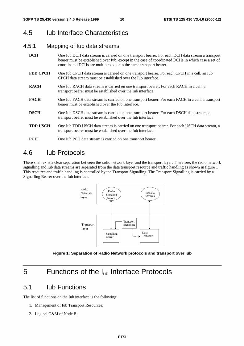
4.6 Iub ProtocolsThere shall exist a clear separation between the radio network layer and the transport layer. Therefore, the radio networksignalling and Iub data streams are separated from the data transport resource and traffic handling as shown in figure 1This resource and traffic handling is controlled by the Transport Signalling. The Transport Signalling is carried by aSignalling Bearer over the Iub interface.
RadioSignalingProtocol
Iub DataStreams
TransportSignalling
SignallingBearer
DataTransport
RadioNetworklayer
Transportlayer
Figure 1: Separation of Radio Network protocols and transport over Iub
5 Functions of the Iub Interface Protocols
5.1 Iub FunctionsThe list of functions on the Iub interface is the following:
1. Management of Iub Transport Resources;
2. Logical O&M of Node B:
ETSI
ETSI TS 125 430 V3.4.0 (2000-12)113GPP TS 25.430 version 3.4.0 Release 1999
- Iub Link Management;
- Cell Configuration Management;
- Radio Network Performance Measurements;
- Resource Event Management;
- Common Transport Channel Management;
- Radio Resource Management;
- Radio Network Configuration Alignment;
3. Implementation Specific O&M Transport;
4. System Information Management;
5. Traffic Management of Common Channels:
- Admission Control;
- Power Management;
- Data Transfer;
6. Traffic Management of Dedicated Channels:
- Radio Link Management;
- Radio Link Supervision;
- Channel Allocation / De-allocation;
- Power Management;
- Measurement Reporting;
- Dedicated Transport Channel Management;
- Data Transfer;
7. Traffic Management of Shared Channels:
- Channel Allocation / De-allocation;
- Power Management;
- Transport Channel Management;
- Dynamic Physical Channel Assignment;
- Radio Link Management;
- Data Transfer;
8. Timing and Synchronization Management:
- Transport Channel Synchronization (Frame synchronization);
- Node B - RNC node Synchronization;
- Inter Node B node Synchronization.
ETSI
ETSI TS 125 430 V3.4.0 (2000-12)123GPP TS 25.430 version 3.4.0 Release 1999
5.2 Functional split over Iub
5.2.1 Management of Iub Transport Resources
The underlying transport resources (AAL2 connections) shall be set up and controlled by the RNC. Further informationon these functions is provided in the transport layer specifications [3], [8], [10].
5.2.2 Logical O&M of Node B
Logical O&M is the signalling associated with the control of logical resources (channels, cells,…) owned by the RNCbut physically implemented in the Node B. The RNC controls these logical resources. A number of O&M proceduresphysically implemented in Node B impact on the logical resources and therefore require an information exchangebetween RNC and Node B. All messages needed to support this information exchange are classified as Logical O&Mforming an integral part of NBAP over the Iub interface.
5.2.2.1 Handling of Node B Hardware Resources
Mapping of Node B logical resources onto Node B hardware resources, used for Iub data streams and radio interfacetransmission/reception, is performed by Node B.
5.2.3 Implementation Specific O&M Transport
The Iub interface may support the transport of Implementation specific O&M information. Further detail on this can befound in the UMTS technical specification on Implementation Specific O&M Transport [2].
5.2.4 System Information Management
System Information is sent by the CRNC to a Node B. CRNC can also request the Node B to autonomously create andupdate certain Node B related system information. Scheduling of system broadcast information is carried out in theCRNC. Scheduling information is always sent by the CRNC to the Node B. The Node B is responsible for transmittingthe received system information according to the scheduling parameters provided. If requested by the CRNC, the NodeB is also responsible for autonomously creating and updating the Node B related system information according to thescheduling parameters provided.
5.2.5 Traffic management of Common Channels
The common channels need to be controlled from the RNC. This is typically the control of the RACH, CPCH [FDD],DSCH and FACH channels, the information that is broadcast on the Broadcast control channel, and the control andrequest for sending information on the paging channels.
5.2.6 Traffic management of Dedicated Channels
These functions are related to the activation of logical resources (e.g. Radio Links, Iub ports), and the connection ofthese various resources together.
Some freedom may be left for Node B implementation on some functions like soft combining for FDD within Node B,since soft combining has merits for being executed as close as possible to the radio (both in terms of transmission costand efficiency).
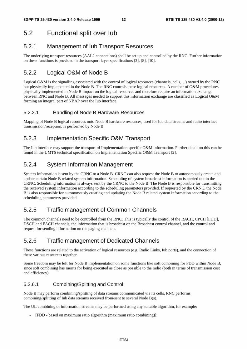
5.2.6.1 Combining/Splitting and Control
Node B may perform combining/splitting of data streams communicated via its cells. RNC performscombining/splitting of Iub data streams received from/sent to several Node B(s).
The UL combining of information streams may be performed using any suitable algorithm, for example:
- [FDD - based on maximum ratio algorithm (maximum ratio combining)];
ETSI
ETSI TS 125 430 V3.4.0 (2000-12)133GPP TS 25.430 version 3.4.0 Release 1999
- [FDD - based on quality information associated to each TBS (selection-combining)];
- [TDD - based on the presence/absence of the signal (selection)].
When requesting the addition of a new cell for a UE-UTRAN connection, the RNC can explicitly request to the Node Ba new Iub data stream, in which case the combining and splitting function within the Node B is not used for that cell.Otherwise, the Node B takes the decision whether combining and splitting function is used inside the Node B for thatcell i.e. whether a new Iub data stream shall be added or not.
The internal Node B handling of the combining/splitting of radio frames is controlled by the Node B.
5.2.6.2 Handover Decision
To support mobility of the UE to UTRAN connection between cells, UTRAN uses measurement reports from the UEand detectors at the cells.
The RNC takes the decision to add or delete cells from the connection.
5.2.6.3 Allocation of Physical Channel Resources
In FDD allocation of downlink channelization codes of cells belonging to Node B is performed in the CRNC.
In TDD allocation of uplink and downlink physical channel resources of cells belonging to Node B is performed in theCRNC.
5.2.6.4 UpLink Power Control
This function controls the level of the transmitted power in order to minimise interference and keep the quality of theconnections. The function uplink Outer Loop Power Control located in the SRNC sets the target quality for the uplinkInner Loop Power Control function. In FDD Inner Loop Power Control Function is located in Node B, while in TDD itis located in the UE.
5.2.6.5 Down-Link Power Control
This function controls the level of the downlink transmitted power. In FDD it is also used to correct the downlink powerdrifting between several radio links. A SRNC regularly (or under some algorithms) shall send the target down linkpower range based on the measurement report from UE.
5.2.6.6 Admission Control
The Admission Control function based on uplink interference and downlink power is located in the CRNC.
Node B shall report uplink interference measurements and downlink power information over the Iub.
The CRNC controls this reporting function, i.e. if this information needs to be reported and the period of these reports.
5.2.6.7 Power and Interference Reporting
A threshold for reporting may be given to Node B from the CRNC to prevent frequent reporting over the Iub. Node Bshall have a function to measure "uplink interference level and downlink TX Power" and a function to compare theaveraged "uplink interference level and downlink TX power" with the threshold value. NodeB shall also have a functionto report when the average measured value exceeds the threshold value. The CRNC shall have a function to modify the"threshold value" for neighbour cell co-ordination.
An indication of exceeding uplink interference threshold or downlink TX power may be included as a cause of failurewhen a Node B is requested to set-up a radio link or add to an existing radio link. This may be used when a number ofradio links set-up requests or additions are received on the Iub during the reporting interval.
ETSI
ETSI TS 125 430 V3.4.0 (2000-12)143GPP TS 25.430 version 3.4.0 Release 1999
5.2.7 Traffic management of Shared Channels
The shared channels shall be controlled from the RNC. This is typically the control of the DSCH channels and the TDDUSCH channels.
5.2.8 Timing and Synchronization Management
The Iub interface shall support timing and synchronization management functions. Further detail regarding thesefunctions can be found in the UMTS technical specification on UTRAN synchronization [12].
6 Node B logical Model over Iub
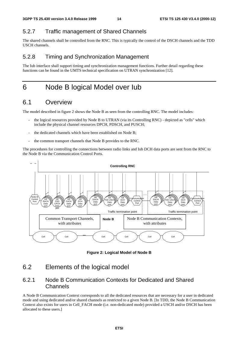
6.1 OverviewThe model described in figure 2 shows the Node B as seen from the controlling RNC. The model includes:
- the logical resources provided by Node B to UTRAN (via its Controlling RNC) - depicted as "cells" whichinclude the physical channel resources DPCH, PDSCH, and PUSCH;
- the dedicated channels which have been established on Node B;
- the common transport channels that Node B provides to the RNC.
The procedures for controlling the connections between radio links and Iub DCH data ports are sent from the RNC tothe Node B via the Communication Control Ports.
.. ..
Node B
...Cell Cell Cell Cell CellCell
Node B Communication Contexts,with attributes
Common Transport Channels,with attributes
Node BControl
PortIub
RACHDataport
IubFACHDataport
IubPCHDataport
Traffic termination point
CommunicationControl
Port
IubTDD USCH
Dataport
IubDCHDataport
IubDSCHDataport
Traffic termination point
CommunicationControl
Port
IubTDD USCH
Dataport
IubDCHDataport
IubDSCHDataport
Controlling RNC
IubFDD
CPCHDataport
Figure 2: Logical Model of Node B
6.2 Elements of the logical model
6.2.1 Node B Communication Contexts for Dedicated and SharedChannels
A Node B Communication Context corresponds to all the dedicated resources that are necessary for a user in dedicatedmode and using dedicated and/or shared channels as restricted to a given Node B. [In TDD, the Node B CommunicationContext also exists for users in Cell_FACH mode (i.e. non-dedicated mode) provided a USCH and/or DSCH has beenallocated to these users.]
ETSI
ETSI TS 125 430 V3.4.0 (2000-12)153GPP TS 25.430 version 3.4.0 Release 1999
There are a number of Node B Communication Contexts inside a given Node B.
The attributes to a Node B Communication Context shall include the following (not exhaustive):
- The list of Cells where dedicated and/or shared physical resources are used.
- The list of DCH which are mapped on the dedicated physical resources for that Node B Communication Context.
- The list of DSCH and (TDD) USCH which are used by the respective UE.
- The complete DCH characteristics for each DCH, identified by its DCH-identifier [4].
- The complete Transport Channel characteristics for each DSCH and USCH, identified by its Shared Channelidentifier [4].
- The list of Iub DCH Data Ports.
- The list of Iub DSCH Data ports and Iub USCH data ports.
- For each Iub DCH Data Port, the corresponding DCH and cells which are carried on this data port.
- For each Iub DSCH and USCH data port, the corresponding DSCH or USCH and cells which serve that DSCHor USCH.
- Physical layer parameters (outer loop power control, etc).
6.2.2 Common Transport Channels
Common Transport Channels are defined in [9]. A Common Transport Channel is configured in the Node B, on requestof the CRNC.
The BCH is carried directly on the Node B control port using NBAP procedures. This Common Channel will not bemapped to an individual data port.
The RACH has an associated Iub RACH Data Port and the FACH has an associated Iub FACH Data Port.
The CPCH [FDD] has an associated Iub CPCH Data Port.
The Iub DSCH data port is associated to one DSCH and to one Node B Communication Context.
[TDD - the Iub USCH data port is associated to one USCH and to one Node B Communication Context.]
The attributes of a Common transport channel shall include (not exhaustive):
- Type (RACH, CPCH [FDD], FACH, DSCH, USCH, PCH).
- Associated Iub RACH Data Port for a RACH, Iub CPCH Data Port for a CPCH [FDD], Iub FACH Data Port fora FACH, Iub PCH Data Port for the PCH.
- List of associated Iub FDD DSCH Data ports for the DSCH (FDD only).
- Physical parameters.
[TDD - In TDD, the DSCHs used by one UE are multiplexed to one or several CCTrCHs where each CCTrCH ismapped to a set of PDSCH ("PDSCH Set"). These PDSCH Sets are included in the Common Transport Channel database. The same applies for the USCHs and the corresponding PUSCH Sets.]
6.2.3 Transport network logical resources
6.2.3.1 Node B Control Port
The Node B Control Port is used to exchange the signalling information for the logical O&M of Node B, the creation ofNode B Communication Contexts, the configuration of the common transport channels that Node B provides in a givencell, PCH and BCH control information between the RNC and the Node B. The Node B Control Port corresponds toone signalling bearer between the controlling RNC and the Node B. There is one Node B Control Port per Node B.
ETSI
ETSI TS 125 430 V3.4.0 (2000-12)163GPP TS 25.430 version 3.4.0 Release 1999
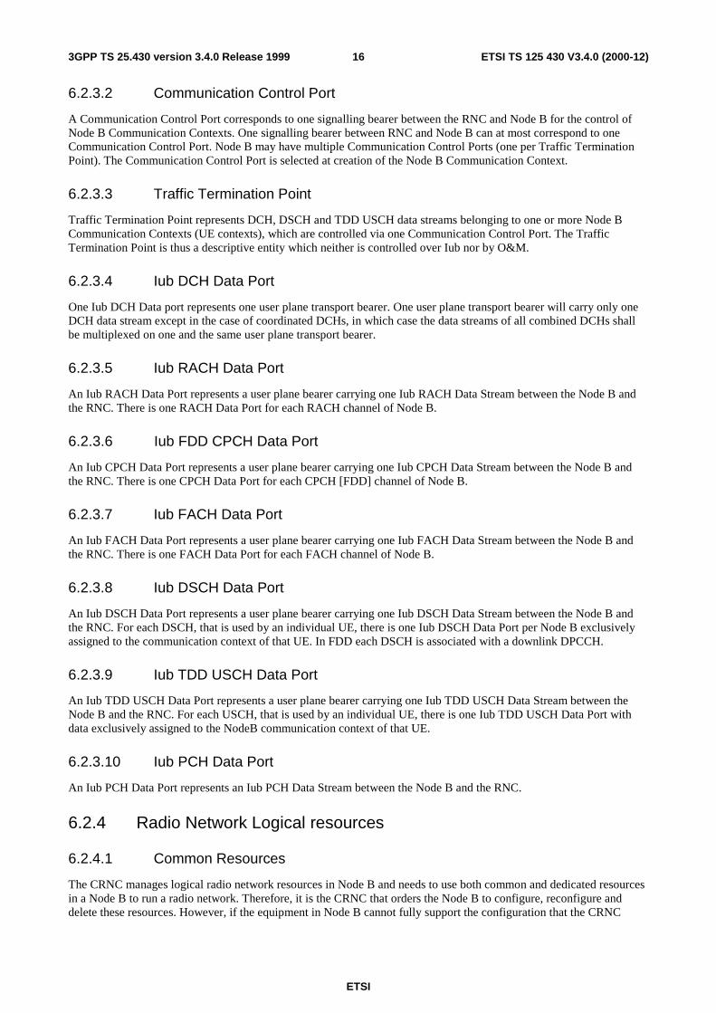
6.2.3.2 Communication Control Port
A Communication Control Port corresponds to one signalling bearer between the RNC and Node B for the control ofNode B Communication Contexts. One signalling bearer between RNC and Node B can at most correspond to oneCommunication Control Port. Node B may have multiple Communication Control Ports (one per Traffic TerminationPoint). The Communication Control Port is selected at creation of the Node B Communication Context.
6.2.3.3 Traffic Termination Point
Traffic Termination Point represents DCH, DSCH and TDD USCH data streams belonging to one or more Node BCommunication Contexts (UE contexts), which are controlled via one Communication Control Port. The TrafficTermination Point is thus a descriptive entity which neither is controlled over Iub nor by O&M.
6.2.3.4 Iub DCH Data Port
One Iub DCH Data port represents one user plane transport bearer. One user plane transport bearer will carry only oneDCH data stream except in the case of coordinated DCHs, in which case the data streams of all combined DCHs shallbe multiplexed on one and the same user plane transport bearer.
6.2.3.5 Iub RACH Data Port
An Iub RACH Data Port represents a user plane bearer carrying one Iub RACH Data Stream between the Node B andthe RNC. There is one RACH Data Port for each RACH channel of Node B.
6.2.3.6 Iub FDD CPCH Data Port
An Iub CPCH Data Port represents a user plane bearer carrying one Iub CPCH Data Stream between the Node B andthe RNC. There is one CPCH Data Port for each CPCH [FDD] channel of Node B.
6.2.3.7 Iub FACH Data Port
An Iub FACH Data Port represents a user plane bearer carrying one Iub FACH Data Stream between the Node B andthe RNC. There is one FACH Data Port for each FACH channel of Node B.
6.2.3.8 Iub DSCH Data Port
An Iub DSCH Data Port represents a user plane bearer carrying one Iub DSCH Data Stream between the Node B andthe RNC. For each DSCH, that is used by an individual UE, there is one Iub DSCH Data Port per Node B exclusivelyassigned to the communication context of that UE. In FDD each DSCH is associated with a downlink DPCCH.
6.2.3.9 Iub TDD USCH Data Port
An Iub TDD USCH Data Port represents a user plane bearer carrying one Iub TDD USCH Data Stream between theNode B and the RNC. For each USCH, that is used by an individual UE, there is one Iub TDD USCH Data Port withdata exclusively assigned to the NodeB communication context of that UE.
6.2.3.10 Iub PCH Data Port
An Iub PCH Data Port represents an Iub PCH Data Stream between the Node B and the RNC.
6.2.4 Radio Network Logical resources
6.2.4.1 Common Resources
The CRNC manages logical radio network resources in Node B and needs to use both common and dedicated resourcesin a Node B to run a radio network. Therefore, it is the CRNC that orders the Node B to configure, reconfigure anddelete these resources. However, if the equipment in Node B cannot fully support the configuration that the CRNC
ETSI
ETSI TS 125 430 V3.4.0 (2000-12)173GPP TS 25.430 version 3.4.0 Release 1999
requests, or the equipment breaks down, then Node B can indicate the availability of the common resources (i.e. bothdowngrade and upgrade).
The common resources are the Cell, the common physical channels and the common transport channels.
In Node B these common resources have an operational state, that indicates whether they are operational or not, i.e.whether they can carry traffic or not.
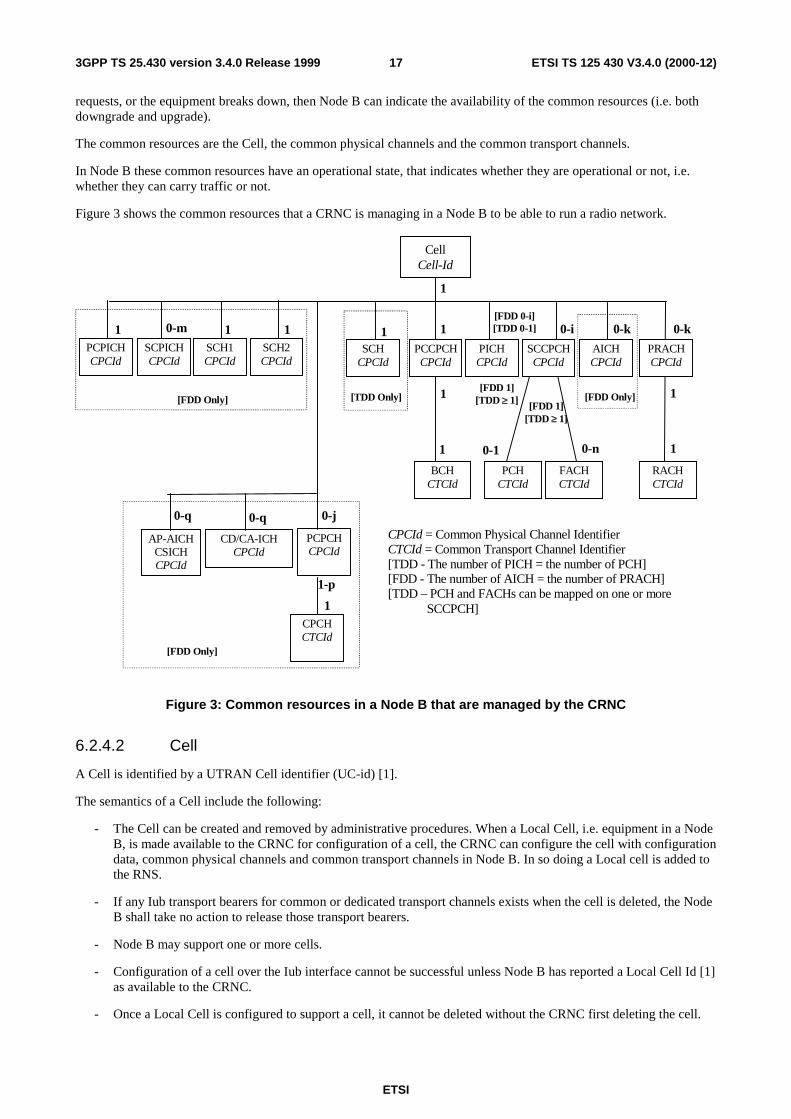
Figure 3 shows the common resources that a CRNC is managing in a Node B to be able to run a radio network.
CellCell-Id
PCPICHCPCId
SCH1CPCId
SCH2CPCId
PCCPCHCPCId
SCPICHCPCId
SCCPCHCPCId
AICHCPCId
PRACHCPCId
BCHCTCId
PCHCTCId
FACHCTCId
RACHCTCId
1
11
1
1
1 1
10-m 0-k0-i 0-k
0-1 0-n
CPCId = Common Physical Channel IdentifierCTCId = Common Transport Channel Identifier[TDD - The number of PICH = the number of PCH][FDD - The number of AICH = the number of PRACH][TDD – PCH and FACHs can be mapped on one or more
SCCPCH]
SCHCPCId
1
[FDD Only] [TDD Only] [FDD Only]
PICHCPCId
[FDD 1][TDD ≥ 1]
[FDD 0-i][TDD 0-1]
1[FDD 1][TDD ≥ 1]
PCPCHCPCId
0-j
CPCHCTCId
[FDD Only]
CD/CA-ICHCPCId
AP-AICHCSICHCPCId
0-q 0-q
1-p
1
Figure 3: Common resources in a Node B that are managed by the CRNC
6.2.4.2 Cell
A Cell is identified by a UTRAN Cell identifier (UC-id) [1].
The semantics of a Cell include the following:
- The Cell can be created and removed by administrative procedures. When a Local Cell, i.e. equipment in a NodeB, is made available to the CRNC for configuration of a cell, the CRNC can configure the cell with configurationdata, common physical channels and common transport channels in Node B. In so doing a Local cell is added tothe RNS.
- If any Iub transport bearers for common or dedicated transport channels exists when the cell is deleted, the NodeB shall take no action to release those transport bearers.
- Node B may support one or more cells.
- Configuration of a cell over the Iub interface cannot be successful unless Node B has reported a Local Cell Id [1]as available to the CRNC.
- Once a Local Cell is configured to support a cell, it cannot be deleted without the CRNC first deleting the cell.
ETSI
ETSI TS 125 430 V3.4.0 (2000-12)183GPP TS 25.430 version 3.4.0 Release 1999
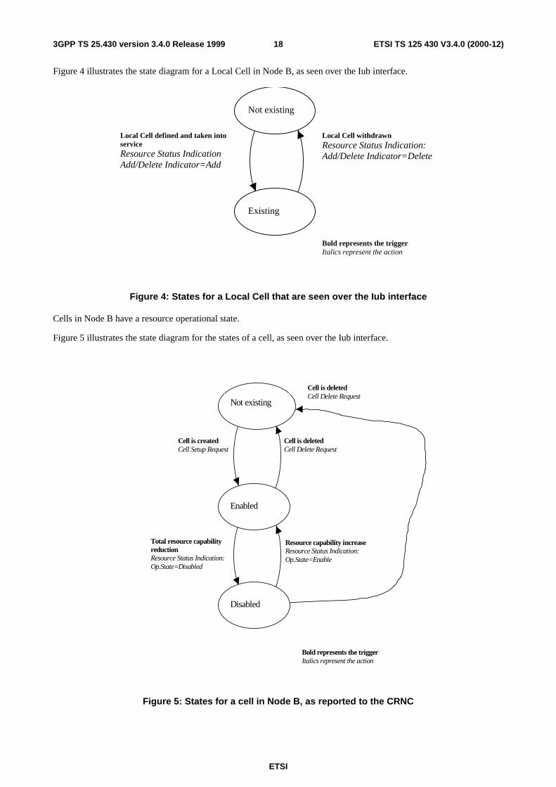
Figure 4 illustrates the state diagram for a Local Cell in Node B, as seen over the Iub interface.
Not existing
Existing
Local Cell defined and taken intoserviceResource Status IndicationAdd/Delete Indicator=Add
Local Cell withdrawnResource Status Indication:Add/Delete Indicator=Delete
Bold represents the triggerItalics represent the action
Figure 4: States for a Local Cell that are seen over the Iub interface
Cells in Node B have a resource operational state.
Figure 5 illustrates the state diagram for the states of a cell, as seen over the Iub interface.
Cell is createdCell Setup Request
Total resource capabilityreductionResource Status Indication:Op.State=Disabled
Resource capability increaseResource Status Indication:Op.State=Enable
Enabled
Disabled
Cell is deletedCell Delete Request
Bold represents the triggerItalics represent the action
Cell is deletedCell Delete Request
Not existing
Figure 5: States for a cell in Node B, as reported to the CRNC
ETSI
ETSI TS 125 430 V3.4.0 (2000-12)193GPP TS 25.430 version 3.4.0 Release 1999
There are three states seen over the Iub interface:
1. Not existing, meaning that the cell does not exist in Node B.
2. enabled, meaning that the resource can be used by the RNC.
3. disabled, meaning that the resource cannot be used by the RNC.
When a cell becomes disabled in Node B, that shall be reported to the CRNC together with the cause.
6.2.4.3 Common Physical Channels and Common Transport Channels
Common physical channels and common transport channels in Node B have a resource operational state.
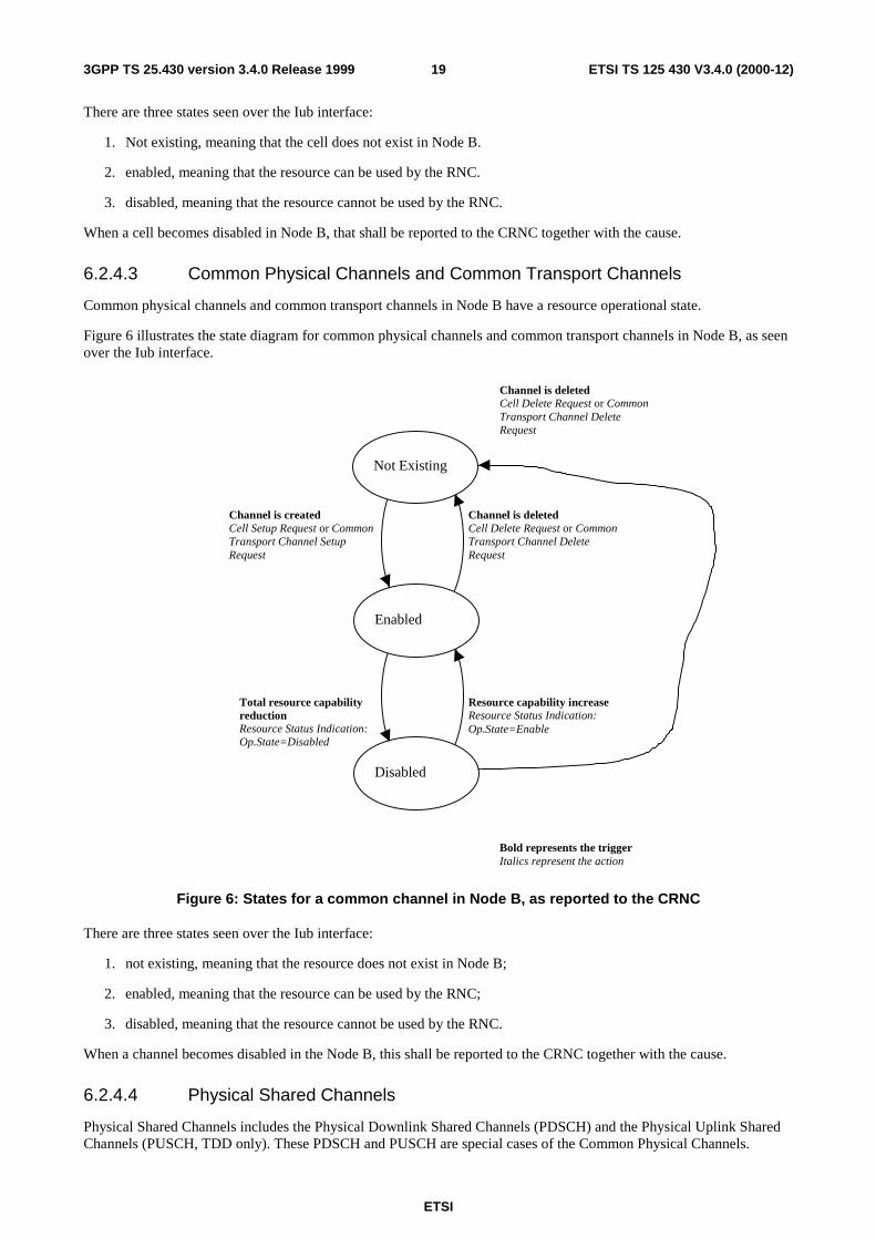
Figure 6 illustrates the state diagram for common physical channels and common transport channels in Node B, as seenover the Iub interface.
Channel is createdCell Setup Request or CommonTransport Channel SetupRequest
Total resource capabilityreductionResource Status Indication:Op.State=Disabled
Resource capability increaseResource Status Indication:Op.State=Enable
Channel is deletedCell Delete Request or CommonTransport Channel DeleteRequest
Bold represents the triggerItalics represent the action
Channel is deletedCell Delete Request or CommonTransport Channel DeleteRequest
Enabled
Disabled
Not Existing
Figure 6: States for a common channel in Node B, as reported to the CRNC
There are three states seen over the Iub interface:
1. not existing, meaning that the resource does not exist in Node B;
2. enabled, meaning that the resource can be used by the RNC;
3. disabled, meaning that the resource cannot be used by the RNC.
When a channel becomes disabled in the Node B, this shall be reported to the CRNC together with the cause.
6.2.4.4 Physical Shared Channels
Physical Shared Channels includes the Physical Downlink Shared Channels (PDSCH) and the Physical Uplink SharedChannels (PUSCH, TDD only). These PDSCH and PUSCH are special cases of the Common Physical Channels.
ETSI
ETSI TS 125 430 V3.4.0 (2000-12)203GPP TS 25.430 version 3.4.0 Release 1999
[FDD - A PDSCH is defined by a channelization code within a code subtree that is configured within a specificCommunication Context. The PDSCH is activated dynamically as part of the DSCH scheduling.]
[TDD - A PDSCH is defined by a channelization code, a time slot and other Physical Channel parameters. SeveralPDSCH may be grouped into a PDSCH Set, which is given a "PDSCH Set Id". The PDSCH Sets are configured in theNode B in the "Common Transport Channel" data base by Common NBAP messages. These PDSCH Sets are availableto carry DSCH data. The PDSCH Sets are dynamically activated to carry DSCH data, as part of the DSCH scheduling.
A PUSCH is defined by a channelization code, a time slot and other Physical Channel parameters. Several PUSCH maybe grouped into a PUSCH Set, which is given a "PUSCH Set Id". The PUSCH Sets are configured in the Node B in the"Common Transport Channel" data base by Common NBAP messages. These PUSCH Sets are available to carryUSCH data. The PUSCH Sets are dynamically activated to carry USCH data, as part of the USCH scheduling.]
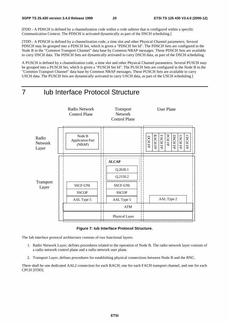
7 Iub Interface Protocol Structure
Node BApplication Part
(NBAP)
AAL Type 2
ALCAP
TransportLayer
Physical Layer
RadioNetworkLayer
Radio NetworkControl Plane
TransportNetwork
Control Plane
DC
H FP
RA
CH
FP
ATM
DSC
H FP
AAL Type 5
User Plane
SSCF-UNI
SSCOP
AAL Type 5
SSCF-UNI
SSCOP
Q.2630.1
Q.2150.2
FAC
H FP
PCH
FP
USC
H FP
CPC
H FP
Figure 7: Iub Interface Protocol Structure.
The Iub interface protocol architecture consists of two functional layers:
1. Radio Network Layer, defines procedures related to the operation of Node B. The radio network layer consists ofa radio network control plane and a radio network user plane.
2. Transport Layer, defines procedures for establishing physical connections between Node B and the RNC.
There shall be one dedicated AAL2 connection for each RACH, one for each FACH transport channel, and one for eachCPCH [FDD].
ETSI
ETSI TS 125 430 V3.4.0 (2000-12)213GPP TS 25.430 version 3.4.0 Release 1999
8 Other Iub Interface Specifications
8.1 UTRAN Iub Interface: Layer 1 (TSG RAN 25.431)This document [5] specifies the standards allowed for the implement of Layer 1 (physical layer) on the Iub interface.
8.2 UTRAN Iub Interface: Signalling Transport (TSG RAN25.432)
This document [6] specifies the signalling transport related to NBAP signalling to be used across the Iub Interface.
8.3 NBAP Specification (TSG RAN 25.433)This document [7] specifies the standards for NBAP specification to be used over Iub Interface.
8.4 UTRAN Iub Interface: Data Transport & TransportSignalling for Common Transport Channel Data Streams(TSG RAN 25.434)
This document [8] provides a specification of the UTRAN RNC-Node B (Iub) interface Data Transport and TransportSignalling for Common Transport Channel data streams.
8.5 UTRAN Iub Interface: User Plane Protocols for CommonTransport Channel Data Streams (TSG RAN 25.435
This document [9] provides a specification of the UTRAN RNC-Node B (Iub) interface user plane protocols forCommon Transport Channel data streams.
8.6 UTRAN Iur/Iub Interface: Data Transport & TransportSignalling for DCH Data Streams (TSG RAN 25.426)
This Technical Specification [10] specifies the transport bearers for the DCH data streams on UTRAN Iur and Iubinterfaces. The corresponding Transport Network Control plane is also specified.
8.7 UTRAN Iur/Iub Interface: User Plane Protocol for DCH DataStreams (TSG RAN 25.427)
This document [11] provides a specification of the UTRAN Iur and Iub interfaces user plane protocols for DedicatedTransport Channel data streams.
ETSI
ETSI TS 125 430 V3.4.0 (2000-12)223GPP TS 25.430 version 3.4.0 Release 1999
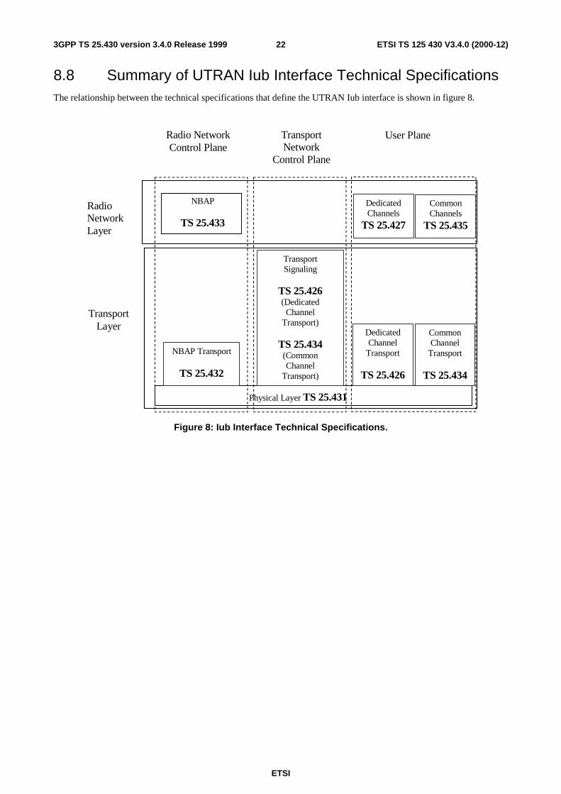
8.8 Summary of UTRAN Iub Interface Technical SpecificationsThe relationship between the technical specifications that define the UTRAN Iub interface is shown in figure 8.
NBAP
TS 25.433
TransportLayer
Physical Layer TS 25.431
RadioNetworkLayer
Radio NetworkControl Plane
TransportNetwork
Control Plane
NBAP Transport
TS 25.432
User Plane
DedicatedChannels
TS 25.427
CommonChannels
TS 25.435
DedicatedChannel
Transport
TS 25.426
CommonChannel
Transport
TS 25.434
TransportSignaling
TS 25.426(Dedicated
ChannelTransport)
TS 25.434(CommonChannel
Transport)
Figure 8: Iub Interface Technical Specifications.
ETSI
ETSI TS 125 430 V3.4.0 (2000-12)233GPP TS 25.430 version 3.4.0 Release 1999
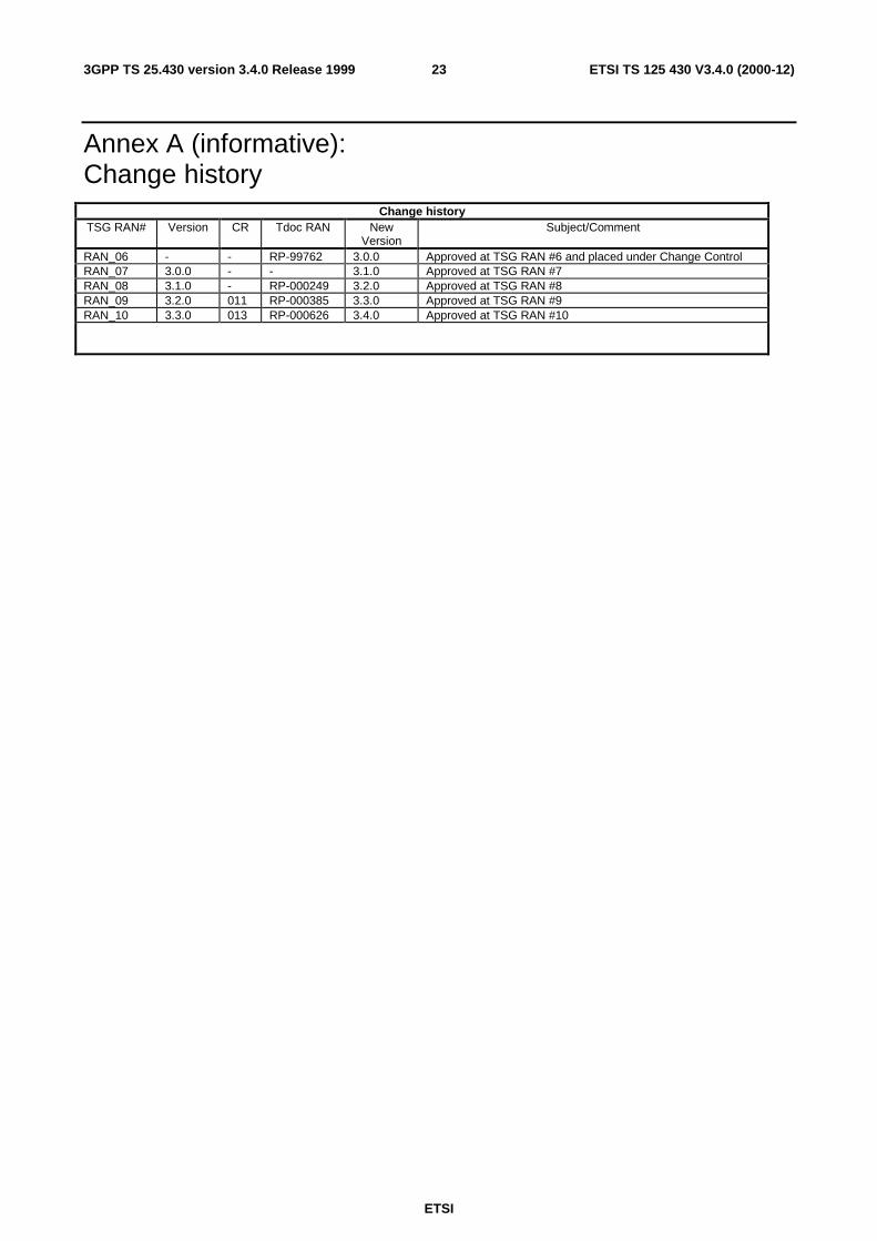
Annex A (informative):Change history
Change historyTSG RAN# Version CR Tdoc RAN New
VersionSubject/Comment
RAN_06 - - RP-99762 3.0.0 Approved at TSG RAN #6 and placed under Change ControlRAN_07 3.0.0 - - 3.1.0 Approved at TSG RAN #7RAN_08 3.1.0 - RP-000249 3.2.0 Approved at TSG RAN #8RAN_09 3.2.0 011 RP-000385 3.3.0 Approved at TSG RAN #9RAN_10 3.3.0 013 RP-000626 3.4.0 Approved at TSG RAN #10
24
ETSI
ETSI TS 125 430 V3.4.0 (2000-12)3GPP TS 25.430 version 3.4.0 Release 1999
History
Document history
V3.0.0 January 2000 Publication
V3.1.0 March 2000 Publication
V3.2.0 June 2000 Publication
V3.3.0 September 2000 Publication
V3.4.0 December 2000 Publication