TS 125 420 - V3.2.0 - Universal Mobile Telecommunications System ...
22
ETSI TS 125 420 V3.2.0 (2000-09) Technical Specification Universal Mobile Telecommunications System (UMTS); UTRAN I ur Interface General Aspects and Principles (3GPP TS 25.420 version 3.2.0 Release 1999)
Transcript of TS 125 420 - V3.2.0 - Universal Mobile Telecommunications System ...
ETSI TS 125 420 V3.2.0 (2000-09)Technical Specification
Universal Mobile Telecommunications System (UMTS);UTRAN Iur Interface General Aspects and Principles
(3GPP TS 25.420 version 3.2.0 Release 1999)

1
ETSI
ETSI TS 125 420 V3.2.0 (2000-09)3GPP TS 25.420 version 3.2.0 Release 1999
ReferenceRTS/TSGR-0325420UR2
KeywordsUMTS
ETSI
650 Route des LuciolesF-06921 Sophia Antipolis Cedex - FRANCE
Tel.: +33 4 92 94 42 00 Fax: +33 4 93 65 47 16
Siret N° 348 623 562 00017 - NAF 742 CAssociation à but non lucratif enregistrée à laSous-Préfecture de Grasse (06) N° 7803/88
Important notice
Individual copies of the present document can be downloaded from:http://www.etsi.org
The present document may be made available in more than one electronic version or in print. In any case of existing orperceived difference in contents between such versions, the reference version is the Portable Document Format (PDF).
In case of dispute, the reference shall be the printing on ETSI printers of the PDF version kept on a specific network drivewithin ETSI Secretariat.
Users of the present document should be aware that the document may be subject to revision or change of status.Information on the current status of this and other ETSI documents is available at http://www.etsi.org/tb/status/
If you find errors in the present document, send your comment to:[email protected]
Copyright Notification
No part may be reproduced except as authorized by written permission.The copyright and the foregoing restriction extend to reproduction in all media.
© European Telecommunications Standards Institute 2000.
All rights reserved.

2
ETSI
ETSI TS 125 420 V3.2.0 (2000-09)3GPP TS 25.420 version 3.2.0 Release 1999
Intellectual Property RightsIPRs essential or potentially essential to the present document may have been declared to ETSI. The informationpertaining to these essential IPRs, if any, is publicly available for ETSI members and non-members, and can be foundin ETSI SR 000 314: "Intellectual Property Rights (IPRs); Essential, or potentially Essential, IPRs notified to ETSI inrespect of ETSI standards", which is available from the ETSI Secretariat. Latest updates are available on the ETSI Webserver (http://www.etsi.org/ipr).
Pursuant to the ETSI IPR Policy, no investigation, including IPR searches, has been carried out by ETSI. No guaranteecan be given as to the existence of other IPRs not referenced in ETSI SR 000 314 (or the updates on the ETSI Webserver) which are, or may be, or may become, essential to the present document.
ForewordThis Technical Specification (TS) has been produced by the ETSI 3rd Generation Partnership Project (3GPP).
The present document may refer to technical specifications or reports using their 3GPP identities, UMTS identities orGSM identities. These should be interpreted as being references to the corresponding ETSI deliverables.
The cross reference between GSM, UMTS, 3GPP and ETSI identities can be found under www.etsi.org/key .

ETSI
ETSI TS 125 420 V3.2.0 (2000-09)33GPP TS 25.420 version 3.2.0 Release 1999
Contents
Foreword.............................................................................................................................................................5
1 Scope ........................................................................................................................................................6
2 References ................................................................................................................................................6
3 Abbreviations ...........................................................................................................................................6
4 General Aspects........................................................................................................................................74.1 Introduction ........................................................................................................................................................74.2 Iur Interface General Principles..........................................................................................................................74.3 Iur Interface Specification Objectives ................................................................................................................74.3.1 General..........................................................................................................................................................74.3.2 Addressing of RNSs over the Iur Interface...................................................................................................84.4 Iur Interface Capabilities ....................................................................................................................................84.4.1 Radio application related signalling..............................................................................................................84.4.2 Iub/Iur DCH data streams .............................................................................................................................84.4.3 Iur RACH/CPCH[FDD] data streams...........................................................................................................84.4.4 Iur DSCH data streams .................................................................................................................................84.4.5 [TDD Iur USCH data streams] .....................................................................................................................84.4.6 Iur FACH data streams .................................................................................................................................94.5 Iur Interface Characteristics ...............................................................................................................................94.5.1 Uses of SCCP ...............................................................................................................................................94.5.1.1 General ....................................................................................................................................................94.5.1.2 SCCP connection establishment..............................................................................................................94.5.1.3 Establishment procedure initiated from the SRNC .................................................................................94.5.1.4 SCCP connection release ......................................................................................................................104.5.1.5 General SCCP Abnormal Conditions....................................................................................................104.5.2 SCCP Addressing Scheme..........................................................................................................................104.5.2.1 General ..................................................................................................................................................10
5 Functions of the Iur Interface Protocols ..................................................................................................115.1 Functional List..................................................................................................................................................115.2 Functional Split over Iur...................................................................................................................................115.2.1 combining/Splitting ....................................................................................................................................115.2.2 Control of Combining/Splitting Topology..................................................................................................125.2.3 Handling of DRNS Hardware Resources....................................................................................................125.2.4 Allocation of Physical Channels.................................................................................................................125.2.5 UpLink Power Control................................................................................................................................125.2.6 Down-Link Power Control .........................................................................................................................125.2.7 Admission Control......................................................................................................................................125.2.8 Radio Protocol Functional Split..................................................................................................................12
6 Iur Interface Protocols .............................................................................................................................126.1 General .............................................................................................................................................................126.2 Radio Signalling Protocols...............................................................................................................................136.2.1 RNSAP Protocol.........................................................................................................................................136.3 User Plane Frame Protocols .............................................................................................................................136.3.1 Iub/Iur DCH Frame Protocol ......................................................................................................................136.3.2 Iur DSCH Frame Protocol ..........................................................................................................................146.3.3 [TDD - Iur USCH Frame Protocol] ............................................................................................................146.3.4 Iur RACH/CPCH[FDD] Frame Protocol....................................................................................................146.3.5 Iur FACH Frame Protocol ..........................................................................................................................146.4 Mapping of Frame Protocols onto transport bearers ........................................................................................15
7 DRNS logical Model over Iur .................................................................................................................157.1 Overview..........................................................................................................................................................157.2 Logical Model Elements ..................................................................................................................................157.2.1 Radio Link ..................................................................................................................................................157.2.2 Cell..............................................................................................................................................................16
ETSI
ETSI TS 125 420 V3.2.0 (2000-09)43GPP TS 25.420 version 3.2.0 Release 1999
7.2.3 Iur DCH Data Port ......................................................................................................................................167.2.4 Iur DSCH Data Port....................................................................................................................................167.2.5 [TDD Iur USCH Data Port] ........................................................................................................................167.2.6 Iur RACH/CPCH[FDD]/FACH Data Port..................................................................................................167.2.7 Iur Control Port...........................................................................................................................................16
8 Iur Interface Protocol Structure ...............................................................................................................17
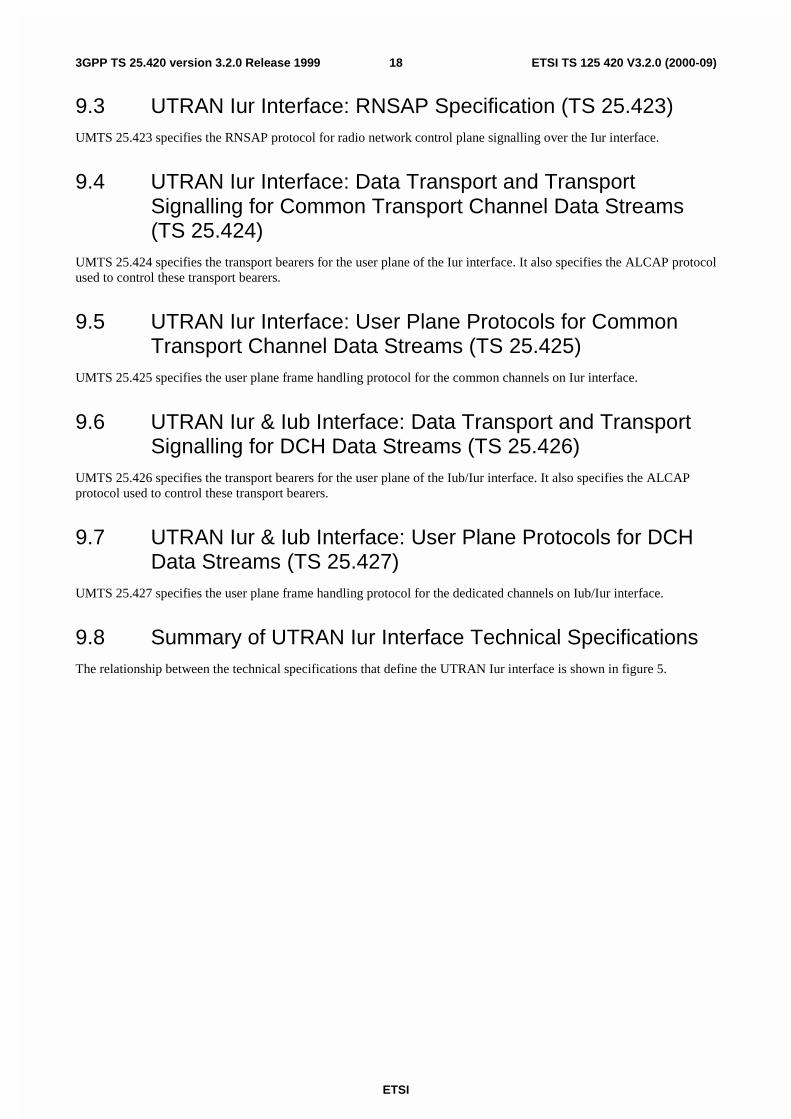
9 Other Iur Interface Specifications ...........................................................................................................179.1 UTRAN Iur Interface: Layer 1 (TS 25.421).....................................................................................................179.2 UTRAN Iur Interface: Signalling Transport (TS 25.422) ................................................................................179.3 UTRAN Iur Interface: RNSAP Specification (TS 25.423) ..............................................................................189.4 UTRAN Iur Interface: Data Transport and Transport Signalling for Common Transport Channel Data
Streams (TS 25.424).........................................................................................................................................189.5 UTRAN Iur Interface: User Plane Protocols for Common Transport Channel Data Streams (TS 25.425) .....189.6 UTRAN Iur & Iub Interface: Data Transport and Transport Signalling for DCH Data Streams (TS
25.426) .............................................................................................................................................................189.7 UTRAN Iur & Iub Interface: User Plane Protocols for DCH Data Streams (TS 25.427) ................................189.8 Summary of UTRAN Iur Interface Technical Specifications...........................................................................18
Annex A (informative): Change history .......................................................................................................20

ETSI
ETSI TS 125 420 V3.2.0 (2000-09)53GPP TS 25.420 version 3.2.0 Release 1999
ForewordThis Technical Specification (TS) has been produced by the 3rd Generation Partnership Project (3GPP).
The contents of the present document are subject to continuing work within the TSG and may change following formalTSG approval. Should the TSG modify the contents of the present document, it will be re-released by the TSG with anidentifying change of release date and an increase in version number as follows:
Version x.y.z
where:
x the first digit:
1 presented to TSG for information;
2 presented to TSG for approval;
3 or greater indicates TSG approved document under change control.
y the second digit is incremented for all changes of substance, i.e. technical enhancements, corrections,updates, etc.
z the third digit is incremented when editorial only changes have been incorporated in the document.

ETSI
ETSI TS 125 420 V3.2.0 (2000-09)63GPP TS 25.420 version 3.2.0 Release 1999
1 ScopeThe present document is an introduction to the TSG RAN TS 25.42x series of UMTS Technical Specifications thatdefine the Iur Interface. It is a logical interface for the interconnection of two Radio Network Controller (RNC)components of the UMTS Terrestrial Radio Access Network (UTRAN) for the UMTS system.
2 ReferencesThe following documents contain provisions which, through reference in this text, constitute provisions of the presentdocument.
• References are either specific (identified by date of publication, edition number, version number, etc.) ornon-specific.
• For a specific reference, subsequent revisions do not apply.
• For a non-specific reference, the latest version applies.
[1] 3GPP TS 25.427: "UTRAN Iub/Iur Interface User Plane Protocol for DCH Data Streams".
[2] 3GPP TS 25.425: "UTRAN Iur Interface: User Plane Protocols for Common Transport ChannelData Streams".
[3] 3GPP TS 25.421: "UTRAN Iur Interface: Layer 1".
[4] 3GPP TS 25.422: "UTRAN Iur Interface: Signalling Transport".
[5] 3GPP TS 25.423: "UTRAN Iur Interface: RNSAP Signalling ".
[6] 3GPP TS 25.424: "UTRAN Iur Interface: Data Transport & Transport Signalling ".
[7] 3GPP TS 25.401: "UTRAN Overall Description".
[8] 3GPP TS 25.426: "UTRAN Iur & Iub Interface: Data Transport & Transport Signalling for DCHData Streams".
[9] ITU-T Recommendation Q.711 (7/96): "Functional description of the signalling connectioncontrol part".
[10] ITU-T Recommendation Q.712 (7/96): "Definition and function of signalling connection controlpart messages".
[11] ITU-T Recommendation Q.713 (7/96): "Signalling connection control part formats and codes".
[12] ITU-T Recommendation Q.714 (7/96): "Signalling connection control part procedures".
[13] 3GPP TS 23.003: "Numbering, Addressing and Identification".
3 AbbreviationsFor the purposes of the present document, the following abbreviations apply:
AAL2 ATM Adaptation Layer type 2AAL5 ATM Adaptation Layer type 5ALCAP Access Link Control Application PartATM Asynchronous Transfer ModeCPCH Common Packet ChannelCRNC Controlling RNCCTP Common Transport ProtocolDCH Dedicated Transport Channel

ETSI
ETSI TS 125 420 V3.2.0 (2000-09)73GPP TS 25.420 version 3.2.0 Release 1999
DL Down-linkDRNC Drift Radio Network ControllerDRNS Drift Radio Network SubsystemDSCH Downlink Shared ChannelFACH Forward Access ChannelGT Global TitleIP Internet ProtocolMAC Medium Access ControlMTP3-B Message Transfer Part level 3 (for Q.2140)PLMN Public Land Mobile NetworkQoS Quality of ServiceRACH Random Access ChannelRF Radio FrequencyRNC Radio Network ControllerRNS Radio Network SubsystemRNSAP Radio Network Subsystem Application PartRRC Radio Resource ControlSCCP Signalling Connection Control PartSPC Signalling Point CodeSRNC Serving Radio Network ControllerSRNS Serving Radio Network SubsystemSS7 Signalling System No 7SSCF-NNI Service Specific Co-ordination Function – Network Node InterfaceSSCOP Service Specific Connection Oriented ProtocolSSN Sub-System NumberSTC Signalling Transport ConverterUE User EquipmentUL Up-linkUMTS Universal Mobile Telecommunication SystemURA UTRAN Registration AreaUSCH Uplink Shared ChannelUTRAN UMTS Terrestrial Radio Access Network
4 General Aspects
4.1 IntroductionThe logical connection that exists between any two RNCs within the UTRAN is referred to as the Iur interface.
4.2 Iur Interface General PrinciplesThe general principles for the specification of the Iur interface are as follows:
- the Iur interface should be open;
- the Iur interface shall support the exchange of signalling information between two RNCs, in addition theinterface may need to support one or more Iur data streams;
- from a logical standpoint, the Iur is a point to point interface between two RNCs within the UTRAN. A point topoint logical interface should be feasible even in the absence of a physical direct connection between the twoRNCs.
4.3 Iur Interface Specification Objectives
4.3.1 General
The Iur interface specifications shall facilitate the following:

ETSI
ETSI TS 125 420 V3.2.0 (2000-09)83GPP TS 25.420 version 3.2.0 Release 1999
- inter-connection of RNCs supplied by different manufacturers;
- support of continuation between RNSs of the UTRAN services offered via the Iu interface;
- separation of Iur interface Radio Network functionality and Transport Network functionality to facilitateintroduction of future technology.
4.3.2 Addressing of RNSs over the Iur Interface
- For an RRC connection using a dedicated channel, the Iur standard shall allow the addition / deletion of radiolinks supported by cells belonging to any RNS within the PLMN.
- The specification of the Iur interface shall allow an RNC to address any other RNC within the PLMN forestablishing a signalling bearer over Iur.
- The specification of the Iur interface shall allow an RNC to address any other RNC within the PLMN forestablishing user data bearers for Iur data streams.
RNSAP shall allow different kinds of addressing schemes to be used for the signalling bearer.
4.4 Iur Interface Capabilities
4.4.1 Radio application related signalling
The Iur interface provides capability to support radio interface mobility between RNSs, of UEs having a connectionwith UTRAN. This capability includes the support of handover, radio resource handling and synchronisation betweenRNSs.
4.4.2 Iub/Iur DCH data streams
The Iur interface provides the means for transport of uplink and downlink Iub/Iur DCH frames carrying user data andcontrol information between SRNC and Node B (DRNS), via the DRNC.
In the UTRAN, one DCH data stream always corresponds to a bi-directional transport channel. Although the TFS isconfigured separately for each DCH direction and a DCH could be configured with e.g. only a zero-bit transport formatin one direction, the DCH is always treated as a bi-directional transport channel in the UTRAN. As a result, two uni-directional Uu DCH transport channels with opposite directions can be mapped to either one or two DCH transportchannels in the UTRAN.
4.4.3 Iur RACH/CPCH[FDD] data streams
The Iur interface provides the means for transport of uplink RACH and [FDD - CPCH] transport frames betweenDRNC and SRNC.
4.4.4 Iur DSCH data streams
An Iur DSCH data stream corresponds to the data carried on one DSCH transport channel for one UE. A UE may havemultiple Iur DSCH data streams.
The Iur interface provides a means of transporting down link MAC-c/sh SDUs. In addition, the interface provides ameans to the SRNC for queue reporting and a means for the DRNC to allocate capacity to the SRNC.
4.4.5 [TDD Iur USCH data streams]
An Iur USCH data stream corresponds to the data carried on one USCH transport channel for one UE. A UE may havemultiple Iur USCH data streams.

ETSI
ETSI TS 125 420 V3.2.0 (2000-09)93GPP TS 25.420 version 3.2.0 Release 1999
4.4.6 Iur FACH data streams
The Iur interface provides the means for transport of downlink FACH transport frames between SRNC and DRNC.
4.5 Iur Interface Characteristics
4.5.1 Uses of SCCP
4.5.1.1 General
The SCCP is used to support signalling messages between two RNCs. One user function of the SCCP, called RadioNetwork Subsystem Application Part (RNSAP), is defined. The RNSAP uses one signalling connection per DRNC andUE where a UE is having one or more active radio links for the transfer of layer 3 messages.
Both connectionless and connection-oriented procedures are used to support the RNSAP. TS 25.423 explains whetherconnection oriented or connectionless services should be used for a layer 3 procedure.
The following subclauses describe the use of SCCP connections for RNSAP transactions. Subclause 2.2 describes theconnection establishment procedures. Subclause 2.3 describes the connection release procedures. Subclause 2.4describes abnormal conditions.
4.5.1.2 SCCP connection establishment
A new SCCP connection is established when information related to the communication between a UE and the networkhas to be exchanged between two RNCs, and no SCCP connection exists between the two RNCs involved, for theconcerned UE.
An SCCP connection is always established by the SRNC.
The above case is the only case currently identified for SCCP connection establishment. Other cases may emerge in thefuture.
4.5.1.3 Establishment procedure initiated from the SRNC
The SCCP signalling connection establishment is initiated, by the SRNC, when the SRNC needs to request dedicatedresources, i.e. a DCH, from a DRNC.
Initiation
- The SRNC sends the SCCP: CR message to the DRNC. The RADIO LINK SETUP REQUEST message may beincluded in the user data field of an SCCP Connection Request message.
Termination
1. Successful outcome:
- The SCCP Connection Confirm message, which may optionally contain a connection oriented RNSAPmessage in the user data field, is returned to the SRNC.
2. Unsuccessful outcome:
- If the SCCP signalling connection establishment fails, an SCCP Connection Refusal message will be sentback to the SRNC. This message may optionally contain a connection oriented RNSAP message.
For more information on how the RNSAP procedure Radio Link Setup is handled, please see the procedure Radio LinkSetup in TS 25.423 [5].

ETSI
ETSI TS 125 420 V3.2.0 (2000-09)103GPP TS 25.420 version 3.2.0 Release 1999
SRNC DRNCCR {SSN=RNSAP, a1=x,
RNSAP message or no user data }
CC {a1=y,a2=x, RNSAP message or no user data}
CREF{a2=x, RNSAP message or no user data}
a1 = source local reference,a2 = destination local referencex = SCCP connection reference at the SRNC,y = SCCP connection reference at the DRNC.
OR
Figure 1: Setting-up of SCCP Signalling Connection
4.5.1.4 SCCP connection release
An SCCP connection is released when the SRNC realises that a given signalling connection is no longer required.
The SRNC sends an SCCP Released message.
4.5.1.5 General SCCP Abnormal Conditions
If a user-out-of-service information or signalling-point-inaccessible information is received by the RNSAP, no newattempt to establish SCCP connections towards the affected point code will be started until the corresponding user-in-service information or signalling-point-accessible information is received.
When a user-out-of-service information or signalling-point-inaccessible is received by an RNC, an optional timer maybe started. When the timer expires, all the SCCP connections towards the affected point code will be released. When theuser-in-service or signalling-point-accessible is received, the timer is stopped.
If for any reason an SCCP connection is released, the optional timer expires or a connection refusal is received whileany of the RNSAP procedures are being performed or while a dedicated resource is still allocated, the following actionsare taken:
At the SRNC:
- Any RNSAP procedure relating to that connection is abandoned.
At the DRNC:
- Any RNSAP procedure relating to that connection is abandoned;
- The DRNS resources (RL's) associated with the SCCP connection are released as soon as possible.
4.5.2 SCCP Addressing Scheme
4.5.2.1 General
RNSAP may use SSN, SPC and/or GT and any combination of them as addressing schemes for the SCCP. Which of theavailable addressing schemes to use for the SCCP is an operator matter.
When GT addressing is utilised, the following settings shall be used:
- SSN Indicator = 1 (RNSAP SSN as defined in [13] shall always be included);
- Global Title Indicator = 0100 (GT includes translation type, numbering plan, encoding scheme and nature ofaddress indicator);

ETSI
ETSI TS 125 420 V3.2.0 (2000-09)113GPP TS 25.420 version 3.2.0 Release 1999
- Translation Type = 0000 0000 (not used);
- Numbering Plan = 0001 (E.163/4);
- Nature of Address Indicator = 000 0100 (International Significant Number);
- Encoding Scheme = 0001 or 0010 (BCD, odd or even);
- Routing indicator = 0 or 1 (route on GT or PC/SSN).
When used, the GT shall be the E.164 address of the relevant node.
5 Functions of the Iur Interface Protocols
5.1 Functional ListThe list of functions on the Iur interface is the following:
1. Transport Network Management.
2. Traffic management of Common Transport Channels:
- Preparation of Common Transport Channel resources;
- Paging.
3. Traffic Management of Dedicated Transport Channels:
- Radio Link Setup/ Addition/ Deletion;
- Measurement Reporting.
4. Traffic Management of Downlink Shared Transport Channels and [TDD Uplink Shared Transport Channels]:
- Radio Link Setup/ Addition/ Deletion;
- Capacity Allocation.
5. Measurement reporting for common and dedicated measurement objects.
5.2 Functional Split over Iur
5.2.1 combining/Splitting
DRNS may perform combining/splitting of data streams communicated via its cells. SRNS performscombining/splitting of Iur data streams received from/sent to DRNS(s), and data streams communicated via its owncells.
The UL combining of information streams may be performed using any suitable algorithm, for example:
- [FDD - based on maximum ratio algorithm (maximum ratio combining)];
- [FDD - based on quality information associated to each TBS (selection-combining)];
- [TDD - based on the presence/absence of the signal (selection)].
The internal DRNS handling of combining (respectively splitting) of Iub (respectively Iur) DCH frames is controlled bythe DRNS.

ETSI
ETSI TS 125 420 V3.2.0 (2000-09)123GPP TS 25.420 version 3.2.0 Release 1999
5.2.2 Control of Combining/Splitting Topology
When requesting the addition of a new cell for a UE-UTRAN connection, the RNC of the SRNS (i.e. the SRNC) canexplicitly request to the RNC of the DRNS (i.e. the DRNC) a new Iur data stream, in which case the combining andsplitting function within the DRNS is not used for that cell. Otherwise, the DRNS takes the decision whether combiningand splitting function is used inside the DRNS for that cell i.e. whether a new Iur data stream shall be added or not.
5.2.3 Handling of DRNS Hardware Resources
Allocation and control of DRNS hardware resources, used for Iur data streams and radio interfacetransmission/reception in DRNS is performed by DRNS.
5.2.4 Allocation of Physical Channels
Allocation of physical channels in cells belonging to DRNS is performed in DRNS.
5.2.5 UpLink Power Control
This group of functions controls the level of the uplink transmitted power in order to minimise uplink interference andkeep the quality of the connections. If the connection involves both a SRNS and a DRNS the function UL Outer LoopPower Control (located in the SRNC) sets the target quality for the UL Inner Loop Power Control function (located inNode B [FDD]).
5.2.6 Down-Link Power Control
This group of functions controls the level of the downlink transmitted power. In FDD it is also used to correct thedownlink power drifting between several radio links. SRNC regularly (or under some algorithms) sends the target downlink power reference based on the measurement report from UE.
5.2.7 Admission Control
Admission control in a DRNC is implicitly invoked during radio link setup/modify.
Information on UL interference and DL power on cells controlled by the DRNC should be available across Iur.
Additional information exchanges between admission control functions located in different RNCs are for further study.
5.2.8 Radio Protocol Functional Split
Iur supports the radio protocol functional split between SRNC and DRNC.
6 Iur Interface Protocols
6.1 GeneralThere shall exist a clear separation between the Radio Network Layer and the Transport Layer. Therefore, the radionetwork signalling and Iur data streams are separated from the data transport resource and traffic handling as shown inFigure 2. Data transport resource and traffic handling is controlled by Transport Signalling. The Transport Signalling iscarried by a Signalling Bearer over the Iur interface.

ETSI
ETSI TS 125 420 V3.2.0 (2000-09)133GPP TS 25.420 version 3.2.0 Release 1999
RadioSignallingProtocols
User PlaneFraming
Protocols
TransportSignalling
SignallingBearer
DataTransport
RadioNetworklayer
Transportlayer
Figure 2: Separation of Radio Network Protocols and transport over Iur
6.2 Radio Signalling Protocols
6.2.1 RNSAP Protocol
The protocol responsible for providing signalling information across the Iur interface is called the Radio NetworkSubsystem Application Part (RNSAP).
The RNSAP is terminated by the two RNCs inter-connected via the Iur interface RNSAP Procedure Modules.
RNSAP procedures are divided into four modules as follows:
1. RNSAP Basic Mobility Procedures;
2. RNSAP DCH Procedures;
3. RNSAP Common Transport Channel Procedures;
4. RNSAP Global Procedures.
The Basic Mobility Procedures module contains procedures used to handle the mobility within UTRAN.
The DCH Procedures module contains procedures that are used to handle DCHs, DSCH and [TDD USCHs] betweentwo RNSs. If procedures from this module are not used in a specific Iur, then the usage of DCH, DSCH and [TDDUSCH] traffic between corresponding RNSs is not possible.
The Common Transport Channel Procedures module contains procedures that are used to control common transportchannel data streams over Iur interface.
The Global Procedures module contains procedures that are not related to a specific UE. The procedures in this moduleare in contrast to the above modules involving two peer CRNCs.
6.3 User Plane Frame Protocols
6.3.1 Iub/Iur DCH Frame Protocol
There are two types of Iub/Iur DCH FP frames:
- DCH data frame;
- DCH control frame.
The contents of the Iub/Iur DCH data frame include:
- Transport Block Sets;

ETSI
ETSI TS 125 420 V3.2.0 (2000-09)143GPP TS 25.420 version 3.2.0 Release 1999
- Quality estimate.
The contents of the Iur DCH control frame include:
- Measurement reports;
- Power control information;
- Synchronisation information.
For a more detailed description of the Iur/Iub DCH frame protocol refer to 'UTRAN Iur & Iub Interface User PlaneProtocol for DCH Data Streams' [1].
6.3.2 Iur DSCH Frame Protocol
There are two types of Iur DSCH FP frames:
- DSCH data frame;
- DSCH control frames.
The contents of the Iur DSCH data frame include:
- MAC-c/sh SDUs;
- User Buffer Status.
The contents of the Iur DSCH control frame include:
- Flow control Information (UL);
- Capacity Request Information (DL).
For a more detailed description of the Iur DSCH frame protocol refer to 'UTRAN Iur Interface User Plane protocols forCommon Transport Channel Data Streams' [2].
6.3.3 [TDD - Iur USCH Frame Protocol]
There is one type of Iur USCH FP frames:
- USCH data frame.
The contents of the Iur USCH data frame include:
- MAC-c/sh SDUs.
For a more detailed description of the Iur USCH frame protocol refer to 'UTRAN Iur Interface User Plane protocols forCommon Transport Channel Data Streams' [2].
6.3.4 Iur RACH/CPCH[FDD] Frame Protocol
For a more detailed description of the Iur RACH framing protocol refer to 'UTRAN Iur Interface User Plane protocolsfor Common Transport Channel Data Streams' [2].
6.3.5 Iur FACH Frame Protocol
For a more detailed description of the Iur FACH framing protocol refer to 'UTRAN Iur Interface User Plane protocolsfor Common Transport Channel Data Streams' [2].

ETSI
ETSI TS 125 420 V3.2.0 (2000-09)153GPP TS 25.420 version 3.2.0 Release 1999
6.4 Mapping of Frame Protocols onto transport bearersDCH One Iur DCH data stream is carried on one transport bearer except in the case of co-
ordinated DCHs in which case a set of co-ordinated DCHs are multiplexed onto the same transport bearer.
DSCH One Iur DSCH data stream is carried on one transport bearer
[TDD USCH One Iur USCH data stream is carried on one transport bearer.]
RACH/CPCH[FDD] Multiple RACH/CPCH[FDD] data streams may be carried on one transport bearer.
FACH Multiple FACH data streams may be carried on one transport bearer.
RACH/CPCH[FDD] and FACH data streams for one UE are carried on same transport bearer.
7 DRNS logical Model over Iur
7.1 OverviewThe model in Figure 3. shows the Drift Radio Network System as seen from the SRNC. It is modelled as a «black box»with a set of Radio Links on the Uu side of the box and another set of User Plane access ports on the Iur side of the box.The Radio Links are connected to the Iur user ports via the internal transport mechanisms of the DRNS. Operations forcontrolling the connections between ports are sent from the SRNC to the DRNC via an Iur Control Plane port.
Radio User Plane
Iur Control Plane
Drift Radio Network System
Radio
Link
Radio
Link
Radio
Link
Iur
Control
Port
Radio
Link
Radio
Link
Radio
Link
Serving Radio Network System
Cell Cell
IurDCHDataPort
RACH/FACHTraffic ContextsWith attributes
IurDCHDataPort
IurDSCHDataPort
IurTDD USCH
DataPort
IurDSCHDataPort
IurRACH/
CPCH[FDD]/FACHDataPort
IurRACH/
CPCH[FDD}/FACHDataPort
Iur
DataPort
TDD USCH
Figure 3: Drift RNS Logical Model
7.2 Logical Model Elements
7.2.1 Radio Link
A Radio Link represents a User Plane access point on the UTRAN side of the Uu interface between the User Equipmentand the UTRAN.
The semantics of a Radio Link include the following:

ETSI
ETSI TS 125 420 V3.2.0 (2000-09)163GPP TS 25.420 version 3.2.0 Release 1999
- It is created, destroyed, and added by SRNC.
- It can be attached to one or more Iur Data Ports at any given time.
- Its resources are allocated and controlled by the DRNS.
7.2.2 Cell
It is defined by:
- A Cell identifier.
The semantics of a Cell include the following:
- It is created and destroyed by administrative procedures.
7.2.3 Iur DCH Data Port
One Iur DCH Data port represents one user plane transport bearer. One user plane transport bearer will carry only oneDCH data stream except in the case of co-ordinated DCHs, in which case the data streams of all co-ordinated DCHsshall be multiplexed on one and the same user plane transport bearer.
The semantics of an Iur DCH Data Port include the following:
- It is created and destroyed by administrative procedures when transport facilities are added to, or deleted from,the Iur interface between the SRNS and DRNS. It can also be created and destroyed dynamically usingdynamically setup transport bearers to add or remove transport facilities.
- It is assigned and released by the SRNC in reaction to requests for bearer services from the UE.
- It may be attached to one or more Radio Links. When attached to Radio Links in the downlink direction, it actsas a point-to-multipoint connection for diversity transmission. When attached to multiple Radio Links in theuplink direction, it acts as a multipoint-to-point connection for diversity reception [FDD].
- The transmit and receive combining/splitting resources required to implement the point-to-multipoint andmultipoint-to-point connections are controlled by the DRNS [FDD].
- The Iur DCH Data Stream emanating from the Iur DCH Data Port terminates in the SRNS connected to DRNS.
7.2.4 Iur DSCH Data Port
One Iur DSCH Data port represents one bi-directional Iur user plane transport bearer. One Iur user plane transportbearer will carry only one DSCH data stream.
7.2.5 [TDD Iur USCH Data Port]
One Iur USCH Data port represents one Iur user plane transport bearer. One Iur user plane transport bearer will carryonly one USCH data stream.
7.2.6 Iur RACH/CPCH[FDD]/FACH Data Port
The Iur RACH/CPCH[FDD]/FACH data port represents a transport bearer and is identified with a transport beareridentity.
7.2.7 Iur Control Port
An Iur Control Port represents the Control Plane access point on the Iur interface between the SRNS and the DRNS. Itis defined by:
- A transport bearer channel identifier.
The semantics of an Iur Control Port include the following:

ETSI
ETSI TS 125 420 V3.2.0 (2000-09)173GPP TS 25.420 version 3.2.0 Release 1999
- It is created via administrative procedures when the Iur interface is created.
8 Iur Interface Protocol StructureThe Iur interface protocol architecture consists of two functional layers:
- Radio Network Layer, defines the procedures related to the interaction of two RNCs within a PLMN. The radionetwork layer consists of a Radio Network Control Plane and a Radio Network User Plane.
- Transport layer, defines procedures for establishing physical connections between two RNCs within a PLMN.
SSCF-NNI
SSCOP
MTP3-B
AAL5
IP
SCTP
SCCP
AAL5
SSCF-NNI
STC (Q.2150.1)
RNSAP Iur DataStream(s)
TransportNetwork
Layer
Physical Layer
TransportUser
NetworkPlane
Control Plane User Plane
TransportUser
NetworkPlane
Transport NetworkControl Plane
RadioNetwork
Layer
ATM
ALCAP(Q.2630.1)
AAL2
SSCF-NNI
SSCOP
MTP3-B
IP
SCTPSSCF-NNI
M3UA M3UA
Figure 4: Iur Interface Protocol Structure
9 Other Iur Interface Specifications
9.1 UTRAN Iur Interface: Layer 1 (TS 25.421)UMTS 25.421 specifies the range of physical layer technologies that may be used to support the Iur interface.
9.2 UTRAN Iur Interface: Signalling Transport (TS 25.422)UMTS 25.422 specifies the signalling bearers for the RNSAP for Iur Interface.
ETSI
ETSI TS 125 420 V3.2.0 (2000-09)183GPP TS 25.420 version 3.2.0 Release 1999
9.3 UTRAN Iur Interface: RNSAP Specification (TS 25.423)UMTS 25.423 specifies the RNSAP protocol for radio network control plane signalling over the Iur interface.
9.4 UTRAN Iur Interface: Data Transport and TransportSignalling for Common Transport Channel Data Streams(TS 25.424)
UMTS 25.424 specifies the transport bearers for the user plane of the Iur interface. It also specifies the ALCAP protocolused to control these transport bearers.
9.5 UTRAN Iur Interface: User Plane Protocols for CommonTransport Channel Data Streams (TS 25.425)
UMTS 25.425 specifies the user plane frame handling protocol for the common channels on Iur interface.
9.6 UTRAN Iur & Iub Interface: Data Transport and TransportSignalling for DCH Data Streams (TS 25.426)
UMTS 25.426 specifies the transport bearers for the user plane of the Iub/Iur interface. It also specifies the ALCAPprotocol used to control these transport bearers.
9.7 UTRAN Iur & Iub Interface: User Plane Protocols for DCHData Streams (TS 25.427)
UMTS 25.427 specifies the user plane frame handling protocol for the dedicated channels on Iub/Iur interface.
9.8 Summary of UTRAN Iur Interface Technical SpecificationsThe relationship between the technical specifications that define the UTRAN Iur interface is shown in figure 5.

ETSI
ETSI TS 125 420 V3.2.0 (2000-09)193GPP TS 25.420 version 3.2.0 Release 1999
RNSAP
TS 25.423
TransportLayer
Physical Layer TS 25.421
RadioNetworkLayer
Radio NetworkControl Plane
TransportNetwork
Control Plane
SignallingTransport
TS 25.422
User Plane
DedicatedChannels
TS 25.427
CommonChannels
TS 25.425
DedicatedChannel
Transport
TS 25.426
CommonChannel
Transport
TS 25.424
TransportSignaling
TS 25.426(Dedicated
ChannelTransport)
TS 25.424(CommonChannel
Transport)
Figure 5: Iur Interface Technical Specifications
ETSI
ETSI TS 125 420 V3.2.0 (2000-09)203GPP TS 25.420 version 3.2.0 Release 1999
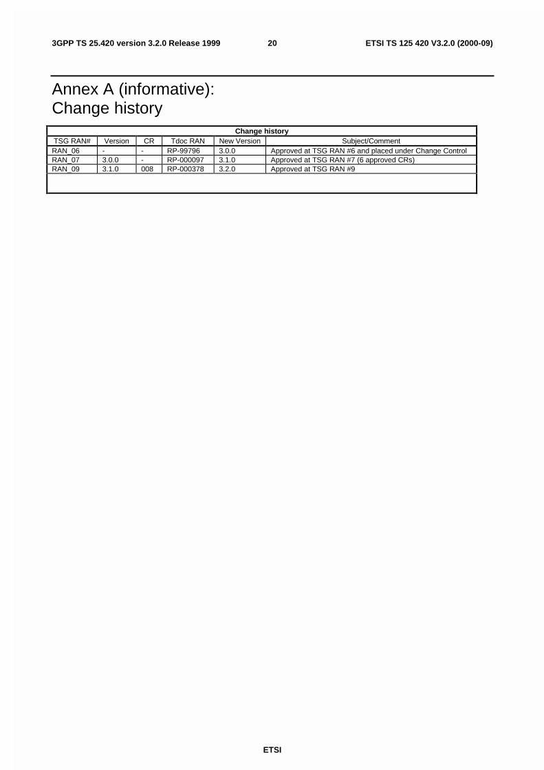
Annex A (informative):Change history
Change historyTSG RAN# Version CR Tdoc RAN New Version Subject/CommentRAN_06 - - RP-99796 3.0.0 Approved at TSG RAN #6 and placed under Change ControlRAN_07 3.0.0 - RP-000097 3.1.0 Approved at TSG RAN #7 (6 approved CRs)RAN_09 3.1.0 008 RP-000378 3.2.0 Approved at TSG RAN #9

21
ETSI
ETSI TS 125 420 V3.2.0 (2000-09)3GPP TS 25.420 version 3.2.0 Release 1999
History
Document history
V3.0.0 January 2000 Publication
V3.1.0 March 2000 Publication
V3.2.0 September 2000 Publication