TS 125 322 - V3.3.0 - Universal Mobile …...2 ETSI 3G TS 25.322 version 3.3.0 Release 1999 ETSI TS...
126
ETSI TS 125 322 V3.3.0 (2000-06) Technical Specification Universal Mobile Telecommunications System (UMTS); RLC Protocol Specification (3G TS 25.322 version 3.3.0 Release 1999)
Transcript of TS 125 322 - V3.3.0 - Universal Mobile …...2 ETSI 3G TS 25.322 version 3.3.0 Release 1999 ETSI TS...
ETSI TS 125 322 V3.3.0 (2000-06)Technical Specification
Universal Mobile Telecommunications System (UMTS);RLC Protocol Specification
(3G TS 25.322 version 3.3.0 Release 1999)
1
ETSI
ETSI TS 125 322 V3.3.0 (2000-06)3G TS 25.322 version 3.3.0 Release 1999
ReferenceRTS/TSGR-0225322UR2
KeywordsUMTS
ETSI
650 Route des LuciolesF-06921 Sophia Antipolis Cedex - FRANCE
Tel.: +33 4 92 94 42 00 Fax: +33 4 93 65 47 16
Siret N° 348 623 562 00017 - NAF 742 CAssociation à but non lucratif enregistrée à laSous-Préfecture de Grasse (06) N° 7803/88
Important notice
Individual copies of the present document can be downloaded from:http://www.etsi.org
The present document may be made available in more than one electronic version or in print. In any case of existing orperceived difference in contents between such versions, the reference version is the Portable Document Format (PDF).
In case of dispute, the reference shall be the printing on ETSI printers of the PDF version kept on a specific network drivewithin ETSI Secretariat.
Users of the present document should be aware that the document may be subject to revision or change of status.Information on the current status of this and other ETSI documents is available at http://www.etsi.org/tb/status/
If you find errors in the present document, send your comment to:[email protected]
Copyright Notification
No part may be reproduced except as authorized by written permission.The copyright and the foregoing restriction extend to reproduction in all media.
© European Telecommunications Standards Institute 2000.
All rights reserved.
2
ETSI
ETSI TS 125 322 V3.3.0 (2000-06)3G TS 25.322 version 3.3.0 Release 1999
Intellectual Property RightsIPRs essential or potentially essential to the present document may have been declared to ETSI. The informationpertaining to these essential IPRs, if any, is publicly available for ETSI members and non-members, and can be foundin SR 000 314: "Intellectual Property Rights (IPRs); Essential, or potentially Essential, IPRs notified to ETSI in respectof ETSI standards", which is available from the ETSI Secretariat. Latest updates are available on the ETSI Web server(http://www.etsi.org/ipr).
Pursuant to the ETSI IPR Policy, no investigation, including IPR searches, has been carried out by ETSI. No guaranteecan be given as to the existence of other IPRs not referenced in SR 000 314 (or the updates on the ETSI Web server)which are, or may be, or may become, essential to the present document.
ForewordThis Technical Specification (TS) has been produced by the ETSI 3rd Generation Partnership Project (3GPP).
The present document may refer to technical specifications or reports using their 3GPP identities, UMTS identities orGSM identities. These should be interpreted as being references to the corresponding ETSI deliverables.
The cross reference between GSM, UMTS, 3GPP and ETSI identities can be found under www.etsi.org/key .
ETSI
ETSI TS 125 322 V3.3.0 (2000-06)33G TS 25.322 version 3.3.0 Release 1999
Contents
Foreword ............................................................................................................................................................ 6
1 Scope........................................................................................................................................................ 7
2 References................................................................................................................................................ 7
3 Abbreviations........................................................................................................................................... 7
4 General..................................................................................................................................................... 84.2 Overview on sublayer architecture .................................................................................................................... 84.2.1 Model of RLC .............................................................................................................................................. 84.2.1.1 Transparent mode entities....................................................................................................................... 94.2.1.2 Unacknowledged mode entities............................................................................................................ 104.2.1.3 Acknowledged mode entity .................................................................................................................. 11
5 Functions................................................................................................................................................ 13
6 Services provided to upper layers .......................................................................................................... 136.1 Mapping of services/functions onto logical channels ...................................................................................... 14
7 Services expected from MAC................................................................................................................ 15
8 Elements for layer-to-layer communication .......................................................................................... 168.1 Primitives between RLC and higher layers...................................................................................................... 16
9 Elements for peer-to-peer communication............................................................................................. 179.1 Protocol data units ........................................................................................................................................... 179.1.1 Data PDUs.................................................................................................................................................. 179.1.2 Control PDUs............................................................................................................................................. 189.2 Formats and parameters ................................................................................................................................... 189.2.1 Formats....................................................................................................................................................... 189.2.1.1 General ................................................................................................................................................. 189.2.1.2 TrD PDU .............................................................................................................................................. 189.2.1.3 UMD PDU............................................................................................................................................ 199.2.1.4 AMD PDU............................................................................................................................................ 199.2.1.5 STATUS PDU...................................................................................................................................... 199.2.1.6 Piggybacked STATUS PDU ................................................................................................................ 209.2.1.7 RESET, RESET ACK PDU ................................................................................................................. 209.2.2 Parameters .................................................................................................................................................. 219.2.2.1 D/C field ............................................................................................................................................... 219.2.2.2 PDU Type............................................................................................................................................. 219.2.2.3 Sequence Number (SN) ........................................................................................................................ 219.2.2.4 Polling bit (P) ....................................................................................................................................... 219.2.2.5 Extension bit (E)................................................................................................................................... 219.2.2.6 Reserved (R)......................................................................................................................................... 229.2.2.7 Header Extension Type (HE) ............................................................................................................... 229.2.2.8 Length Indicator (LI) ............................................................................................................................ 229.2.2.9 Data ...................................................................................................................................................... 239.2.2.10 Padding (PAD) ..................................................................................................................................... 249.2.2.11 SUFI ..................................................................................................................................................... 249.2.2.11.1 The No More Data super-field ........................................................................................................ 249.2.2.11.2 The Acknowledgement super-field ................................................................................................. 249.2.2.11.3 The Window Size super-field ......................................................................................................... 259.2.2.11.4 The List super-field......................................................................................................................... 259.2.2.11.5 The Bitmap super-field ................................................................................................................... 269.2.2.11.6 The Relative List super-field........................................................................................................... 269.2.2.11.7 The Move Receiving Window super-field ...................................................................................... 279.2.2.11.8 The Move Receiving Window and Ignore First LI (MRW_N_IFL) super-field............................. 289.2.2.12 Reserved (R)......................................................................................................................................... 289.2.2.13 Reset Sequence Number (RSN)............................................................................................................ 28
ETSI
ETSI TS 125 322 V3.3.0 (2000-06)43G TS 25.322 version 3.3.0 Release 1999
9.3 Protocol states.................................................................................................................................................. 299.3.1 State model for transparent mode entities .................................................................................................. 299.3.1.1 Null State .............................................................................................................................................. 299.3.1.2 Transparent Data Transfer Ready State ................................................................................................ 299.3.2 State model for unacknowledged mode entities ......................................................................................... 299.3.2.1 Null State .............................................................................................................................................. 299.3.2.2 Unacknowledged Data Transfer Ready State ....................................................................................... 299.3.2.3 Local Suspend State.............................................................................................................................. 299.3.3 State model for acknowledged mode entities ............................................................................................. 309.3.3.1 Null State .............................................................................................................................................. 309.3.3.2 Acknowledged Data Transfer Ready State ........................................................................................... 309.3.3.3 Reset Pending State .............................................................................................................................. 309.3.3.4 Local Suspend State.............................................................................................................................. 319.4 State variables.................................................................................................................................................. 319.5 Timers.............................................................................................................................................................. 339.6 Protocol Parameters ......................................................................................................................................... 349.7 Specific functions ............................................................................................................................................ 359.7.1 Polling function for acknowledged mode transfer ..................................................................................... 359.7.2 STATUS transmission for acknowledged mode ........................................................................................ 369.7.3 SDU discard function................................................................................................................................. 369.7.3.1 Timer based discard, with explicit signalling ....................................................................................... 379.7.3.2 Timer based discard, without explicit signalling .................................................................................. 379.7.3.3 SDU discard after MaxDAT number of retransmissions...................................................................... 379.7.4 The Estimated PDU Counter...................................................................................................................... 379.7.5 Multiple payload units in an RLC PDU ..................................................................................................... 389.7.6 Local Suspend function for acknowledged mode transfer ......................................................................... 38
10 Handling of unknown, unforeseen and erroneous protocol data ........................................................... 38
11 Elementary procedures .......................................................................................................................... 3811.1 Transparent mode data transfer procedure....................................................................................................... 3811.1.1 Purpose....................................................................................................................................................... 3811.1.2 Initiation ..................................................................................................................................................... 3911.1.2.1 TrD PDU contents to set....................................................................................................................... 3911.1.3 Reception of TrD PDU............................................................................................................................... 3911.1.4 Abnormal cases .......................................................................................................................................... 3911.1.4.1 Undefined SDU size at receiver ........................................................................................................... 3911.1.4.2 SDU discard without explicit signalling............................................................................................... 3911.2 Unacknowledged mode data transfer procedure .............................................................................................. 3911.2.1 Purpose....................................................................................................................................................... 3911.2.2 Initiation ..................................................................................................................................................... 4011.2.2.1 UMD PDU contents to set .................................................................................................................... 4011.2.3 Reception of UMD PDU............................................................................................................................ 4011.2.4 Abnormal cases .......................................................................................................................................... 4011.2.4.1 Length Indicator value 1111110........................................................................................................... 4011.2.4.2 Invalid length indicator value ............................................................................................................... 4011.2.4.3 SDU discard without explicit signalling............................................................................................... 4111.3 Acknowledged mode data transfer procedure.................................................................................................. 4111.3.1 Purpose....................................................................................................................................................... 4111.3.2 Initiation ..................................................................................................................................................... 4111.3.2.1 AMD PDU contents to set .................................................................................................................... 4111.3.2.1.1 Setting of the Polling bit ................................................................................................................. 4211.3.2.1.2 Segmentation of a SDU .................................................................................................................. 4211.3.3 Reception of AMD PDU by the receiver ................................................................................................... 4211.3.4 Abnormal cases .......................................................................................................................................... 4211.3.4.1 Timer_Poll timeout............................................................................................................................... 4211.3.4.2 Receiving a PU outside the receiving window ..................................................................................... 4311.3.4.3 Timer_Discard timeout......................................................................................................................... 4311.3.4.3.1 SDU discard with explicit signalling .............................................................................................. 4311.3.4.4 VT(DAT) > MaxDAT .......................................................................................................................... 4311.3.4.5 Invalid length indicator value ............................................................................................................... 4311.4 RLC reset procedure ........................................................................................................................................ 43
ETSI
ETSI TS 125 322 V3.3.0 (2000-06)53G TS 25.322 version 3.3.0 Release 1999
11.4.1 Purpose....................................................................................................................................................... 4311.4.2 Initiation ..................................................................................................................................................... 4311.4.2.1 RESET PDU contents to set ................................................................................................................. 4411.4.3 Reception of the RESET PDU by the receiver........................................................................................... 4411.4.3.1 RESET ACK PDU contents to set........................................................................................................ 4411.4.4 Reception of the RESET ACK PDU by the sender.................................................................................... 4411.4.5 Abnormal cases .......................................................................................................................................... 4411.4.5.1 Timer_RST timeout.............................................................................................................................. 4411.4.5.2 VT(RST) ≥ MaxRST............................................................................................................................ 4411.4.5.3 Reception of the RESET PDU by the sender ....................................................................................... 4411.5 STATUS report transfer procedure.................................................................................................................. 4511.5.1 Purpose....................................................................................................................................................... 4511.5.2 Initiation ..................................................................................................................................................... 4511.5.2.1 Piggybacked STATUS PDU ................................................................................................................ 4511.5.2.2 STATUS PDU contents to set .............................................................................................................. 4611.5.3 Reception of the STATUS PDU by the sender .......................................................................................... 4611.5.4 Abnormal cases .......................................................................................................................................... 4611.5.4.1 EPC reaches zero and the requested PUs have not been received ........................................................ 4611.6 SDU discard with explicit signalling procedure .............................................................................................. 4611.6.1 Purpose....................................................................................................................................................... 4611.6.2 Initiation ..................................................................................................................................................... 4711.6.2.1 Piggybacked STATUS PDU ................................................................................................................ 4711.6.2.2 STATUS PDU contents to set .............................................................................................................. 4711.6.3 Reception of the STATUS PDU by the receiver........................................................................................ 4711.6.4 Reception of STATUS PDU if VR(R) ≥ SN_MRWLENGTH........................................................................ 4711.6.5 Expiration of timer Timer_MRW............................................................................................................... 4811.6.6 Abnormal cases .......................................................................................................................................... 4811.6.6.1 Obsolete/corrupted MRW command.................................................................................................... 4811.6.6.2 VT(MRW) equals MaxMRW............................................................................................................... 48
Annex A (informative): SDL diagrams ................................................................................................ 49
Annex B (informative): Pseudo code describing AMD PDU header Compression ....................... 123
Annex C (informative): Change history............................................................................................. 124

ETSI
ETSI TS 125 322 V3.3.0 (2000-06)63G TS 25.322 version 3.3.0 Release 1999
ForewordThis Technical Specification (TS) has been produced by the 3rd Generation Partnership Project (3GPP).
The contents of the present document are subject to continuing work within the TSG and may change following formalTSG approval. Should the TSG modify the contents of the present document, it will be re-released by the TSG with anidentifying change of release date and an increase in version number as follows:
Version x.y.z
where:
x the first digit:
1 presented to TSG for information;
2 presented to TSG for approval;
3 or greater indicates TSG approved document under change control.
y the second digit is incremented for all changes of substance, i.e. technical enhancements, corrections,updates, etc.
z the third digit is incremented when editorial only changes have been incorporated in the document.
ETSI
ETSI TS 125 322 V3.3.0 (2000-06)73G TS 25.322 version 3.3.0 Release 1999
1 ScopeThe present document specifies the RLC protocol.
Release '99 features:
- Transparent mode.
- Unacknowledged mode.
- Acknowledged mode.
Features for future Releases:
- Hybrid ARQ.
2 ReferencesThe following documents contain provisions which, through reference in this text, constitute provisions of the presentdocument.
• References are either specific (identified by date of publication, edition number, version number, etc.) ornon-specific.
• For a specific reference, subsequent revisions do not apply.
• For a non-specific reference, the latest version applies.
[1] 3G TS 25.401: "UTRAN Overall Description".
[2] 3G TR 25.990: "Vocabulary for the UTRAN".
[3] 3G TS 25.301: "Radio Interface Protocol Architecture".
[4] 3G TS 25.302: "Services Provided by the Physical Layer".
[5] 3G TS 25.303: "Interlayer Procedures in Connected Mode".
[6] 3G TS 25.304: "UE Procedures in Idle Mode and Procedures for Cell Reselection in ConnectedMode".
[7] 3G TS 25.321: "MAC Protocol Specification".
[8] 3G TS 25.331: "RRC Protocol Specification".
3 AbbreviationsFor the purposes of the present document, the following abbreviations apply:
ARQ Automatic Repeat RequestBCCH Broadcast Control ChannelBCH Broadcast ChannelC- Control-CCCH Common Control ChannelCCH Control ChannelCCTrCH Coded Composite Transport ChannelCRC Cyclic Redundancy CheckDCCH Dedicated Control ChannelDCH Dedicated ChannelDL Downlink
ETSI
ETSI TS 125 322 V3.3.0 (2000-06)83G TS 25.322 version 3.3.0 Release 1999
DSCH Downlink Shared ChannelDTCH Dedicated Traffic ChannelFACH Forward Link Access ChannelFDD Frequency Division DuplexL1 Layer 1 (physical layer)L2 Layer 2 (data link layer)L3 Layer 3 (network layer)LSB Least Significant BitMAC Medium Access ControlMRW Move Receive WindowMSB Most Significant BitPCCH Paging Control ChannelPCH Paging ChannelPDU Protocol Data UnitPU Payload Unit.PHY Physical layerPhyCH Physical ChannelsRACH Random Access ChannelRLC Radio Link ControlRRC Radio Resource ControlSAP Service Access PointSDU Service Data UnitSHCCH Shared Channel Control ChannelTCH Traffic ChannelTDD Time Division DuplexTFI Transport Format IndicatorU- User-UE User EquipmentUL UplinkUMTS Universal Mobile Telecommunications SystemUTRA UMTS Terrestrial Radio AccessUTRAN UMTS Terrestrial Radio Access Network
4 General
4.2 Overview on sublayer architectureThe model presented in this section is not for implementation purposes.
4.2.1 Model of RLC
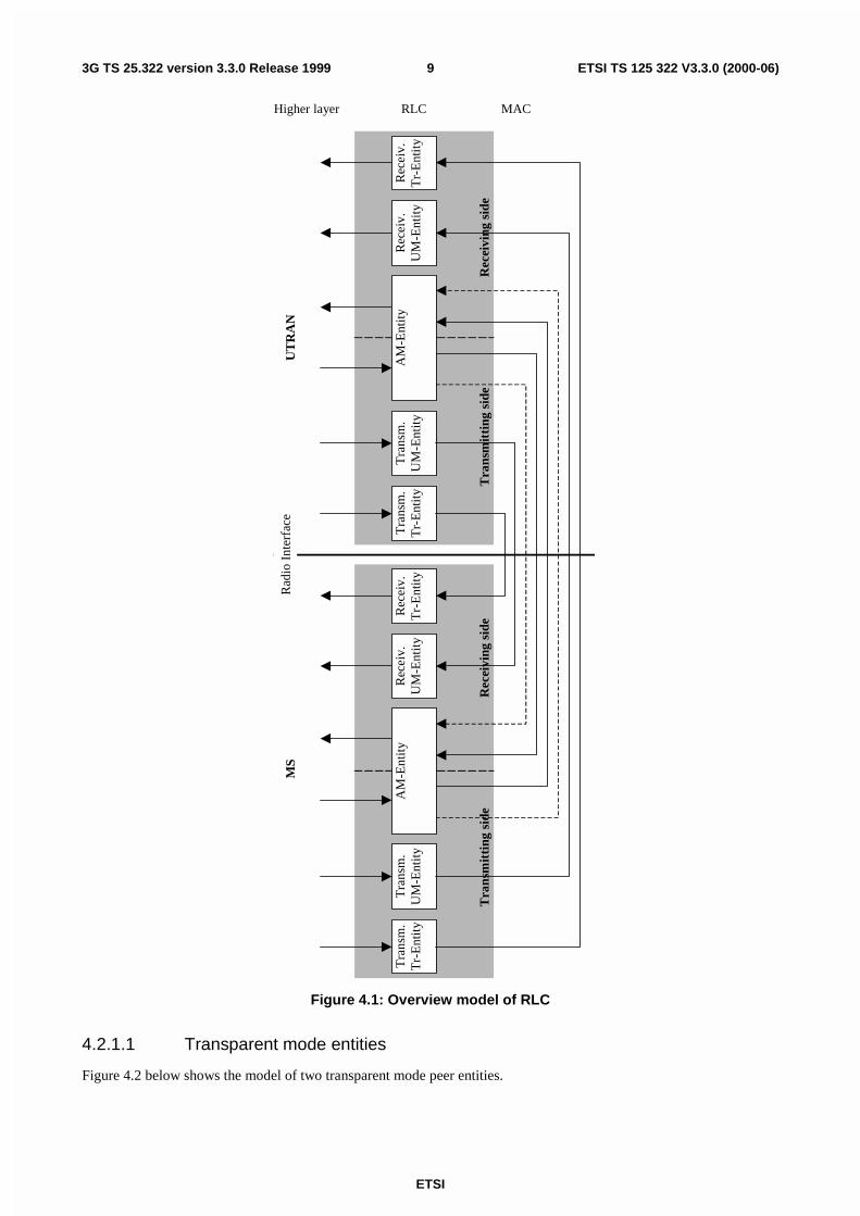
Figure 4.1 gives an overview model of the RLC layer. The figure illustrates the different RLC peer entities. There is onetransmitting and one receiving entity for the transparent mode service and the unacknowledged mode service and onecombined transmitting and receiving entity for the acknowledged mode service. The dashed lines between the AM-Entities illustrate the possibility to send the RLC PDUs on separate logical channels, e.g. control PDUs on one and dataPDUs on the other. More detailed descriptions of the different entities are given in subclauses 4.2.1.1, 4.2.1.2 and4.2.1.3.
ETSI
ETSI TS 125 322 V3.3.0 (2000-06)93G TS 25.322 version 3.3.0 Release 1999
Tra
nsm
.U
M-E
ntit
yT
rans
m.
Tr-
Ent
ity
UT
RA
N
Tra
nsm
itti
ng s
ide
Rec
eivi
ng s
ide
MS
Rad
io I
nter
face
RLC MACHigher layer
Rec
eiv.
UM
-Ent
ity
Rec
eiv.
Tr-
Ent
ity
Tra
nsm
.U
M-E
ntit
yT
rans
m.
Tr-
Ent
ity
Rec
eiv.
UM
-Ent
ity
Rec
eiv.
Tr-
Ent
ity
Tra
nsm
itti
ng s
ide
Rec
eivi
ng s
ide
AM
-Ent
ity
AM
-Ent
ity
Figure 4.1: Overview model of RLC
4.2.1.1 Transparent mode entities
Figure 4.2 below shows the model of two transparent mode peer entities.
ETSI
ETSI TS 125 322 V3.3.0 (2000-06)103G TS 25.322 version 3.3.0 Release 1999
Transm.Tr-Entity
Transmissionbuffer
Segmentation
Tr-SAP
BCCH/PCCH/DCCHCCCH/DTCH/SHCCH
ReceivingTr-Entity
Receiver buffer
Reassembly
Tr-SAP
Radio Interface
BCCH/PCCH/DCCHCCCH/DTCH/SHCCH
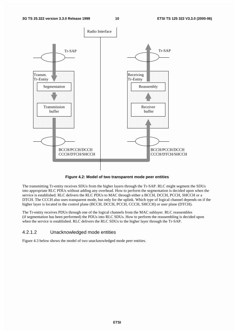
Figure 4.2: Model of two transparent mode peer entities
The transmitting Tr-entity receives SDUs from the higher layers through the Tr-SAP. RLC might segment the SDUsinto appropriate RLC PDUs without adding any overhead. How to perform the segmentation is decided upon when theservice is established. RLC delivers the RLC PDUs to MAC through either a BCCH, DCCH, PCCH, SHCCH or aDTCH. The CCCH also uses transparent mode, but only for the uplink. Which type of logical channel depends on if thehigher layer is located in the control plane (BCCH, DCCH, PCCH, CCCH, SHCCH) or user plane (DTCH).
The Tr-entity receives PDUs through one of the logical channels from the MAC sublayer. RLC reassembles(if segmentation has been performed) the PDUs into RLC SDUs. How to perform the reassembling is decided uponwhen the service is established. RLC delivers the RLC SDUs to the higher layer through the Tr-SAP.
4.2.1.2 Unacknowledged mode entities
Figure 4.3 below shows the model of two unacknowledged mode peer entities.
ETSI
ETSI TS 125 322 V3.3.0 (2000-06)113G TS 25.322 version 3.3.0 Release 1999
T r a n s m .U M -E n t i ty
T r a n s m is s io nb u ffe r
U M -S A P
R e c e iv e rU M -E n t i ty
R e c e iv e rb u f fe r
U M -S A P
R a d io I n te r fa c e
S e g m e n ta t io n &C o n c a te n a t io n
C ip h e r in g
A d d R L C h e a d e r
R e a s s e m b ly
D e c ip h e r in g
R e m o v e R L Ch e a d e r
C C C H /D C C H /D T C H /S H C C HC T C H
C C C H /D C C H /DT C H / S H C C HC T C H
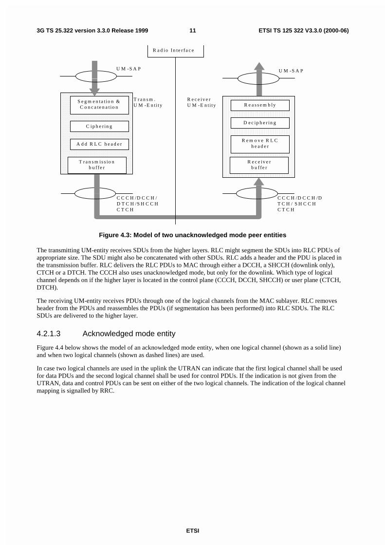
Figure 4.3: Model of two unacknowledged mode peer entities
The transmitting UM-entity receives SDUs from the higher layers. RLC might segment the SDUs into RLC PDUs ofappropriate size. The SDU might also be concatenated with other SDUs. RLC adds a header and the PDU is placed inthe transmission buffer. RLC delivers the RLC PDUs to MAC through either a DCCH, a SHCCH (downlink only),CTCH or a DTCH. The CCCH also uses unacknowledged mode, but only for the downlink. Which type of logicalchannel depends on if the higher layer is located in the control plane (CCCH, DCCH, SHCCH) or user plane (CTCH,DTCH).
The receiving UM-entity receives PDUs through one of the logical channels from the MAC sublayer. RLC removesheader from the PDUs and reassembles the PDUs (if segmentation has been performed) into RLC SDUs. The RLCSDUs are delivered to the higher layer.
4.2.1.3 Acknowledged mode entity
Figure 4.4 below shows the model of an acknowledged mode entity, when one logical channel (shown as a solid line)and when two logical channels (shown as dashed lines) are used.
In case two logical channels are used in the uplink the UTRAN can indicate that the first logical channel shall be usedfor data PDUs and the second logical channel shall be used for control PDUs. If the indication is not given from theUTRAN, data and control PDUs can be sent on either of the two logical channels. The indication of the logical channelmapping is signalled by RRC.
ETSI
ETSI TS 125 322 V3.3.0 (2000-06)123G TS 25.322 version 3.3.0 Release 1999
T ra n sm iss io nb u ffe r
R e tra n sm iss io nb u ffe r &
m a n g e m e n t
M U X
S e t f ie ld s in R L C H e a d e r (e .g . s e tp o ll b its ) .
R L C C o n tro l U n it
Re
ce
ive
d a
ck
no
wle
dg
e
A c k n o w le d g e m e n ts
D C C H /D T C H *
A M -S A P
D C C H /D T C H * *
D C C H /D T C H * *
A M -E n tity
D e m u x /R o u tin g
D C C H /D T C H *
D C C H /D T C H * *
D C C H /D T C H * *
R e c e iv e r b u ffe r &R e tra n sm iss io n
m a n a g e m e n t
T r a n sm it t in g S id e R e c e iv in g S id e
S e g m e n ta tio n /C o n c a te n a tio n
C ip h e r in g
A d d R L C h e a d e r
R e a sse m b ly
D e c ip h e rin g
R e m o v e R L C h e a d e r & E x tra c tP ig g yb a c k e d in fo rm a tio n
P ig g yb a c k e d s ta tu sO p tio n a l
Figure 4.4: Model of a acknowledged mode entity
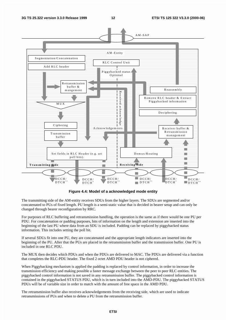
The transmitting side of the AM-entity receives SDUs from the higher layers. The SDUs are segmented and/orconcatenated to PUs of fixed length. PU length is a semi-static value that is decided in bearer setup and can only bechanged through bearer reconfiguration by RRC.
For purposes of RLC buffering and retransmission handling, the operation is the same as if there would be one PU perPDU. For concatenation or padding purposes, bits of information on the length and extension are inserted into thebeginning of the last PU where data from an SDU is included. Padding can be replaced by piggybacked statusinformation. This includes setting the poll bit.
If several SDUs fit into one PU, they are concatenated and the appropriate length indicators are inserted into thebeginning of the PU. After that the PUs are placed in the retransmission buffer and the transmission buffer. One PU isincluded in one RLC PDU.
The MUX then decides which PDUs and when the PDUs are delivered to MAC. The PDUs are delivered via a functionthat completes the RLC-PDU header. The fixed 2 octet AMD PDU header is not ciphered.
When Piggybacking mechanism is applied the padding is replaced by control information, in order to increase thetransmission efficiency and making possible a faster message exchange between the peer to peer RLC entities. Thepiggybacked control information is not saved in any retransmission buffer. The piggybacked control information iscontained in the piggybacked STATUS PDU, which is in turn included into the AMD-PDU. The piggybacked STATUSPDUs will be of variable size in order to match with the amount of free space in the AMD PDU.
The retransmission buffer also receives acknowledgements from the receiving side, which are used to indicateretransmissions of PUs and when to delete a PU from the retransmission buffer.
ETSI
ETSI TS 125 322 V3.3.0 (2000-06)133G TS 25.322 version 3.3.0 Release 1999
The Receiving Side of the AM-entity receives PDUs through one of the logical channels from the MAC sublayer. TheRLC-PDUs are expanded into separate PUs and potential piggybacked status information are extracted. The PUs areplaced in the receiver buffer until a complete SDU has been received. The receiver buffer requests retransmissions ofPUs by sending negative acknowledgements to the peer entity. After that the headers are removed from the PDUs andthe PDUs are reassembled into a SDU. Finally the SDU is delivered to the higher layer. The receiving side also receivesacknowledgements from the peer entity. The acknowledgements are passed to the retransmission buffer on thetransmitting side.
5 FunctionsThe following functions are supported by RLC. For a detailed description of the following functions see [3]:
- Segmentation and reassembly.
- Concatenation.
- Padding.
- Transfer of user data.
- Error correction.
- In-sequence delivery of higher layer PDUs.
- Duplicate Detection.
- Flow control.
- Sequence number check (Unacknowledged data transfer mode).
- Protocol error detection and recovery.
- Ciphering.
- Suspend/resume function.
6 Services provided to upper layersThis clause describes the different services provided by RLC to higher layers. It also includes mapping of functions todifferent services. For a detailed description of the following functions see [3].
- Transparent data transfer Service.
The following functions are needed to support transparent data transfer:
- Segmentation and reassembly.
- Transfer of user data.
- Unacknowledged data transfer Service:
The following functions are needed to support unacknowledged data transfer:
- Segmentation and reassembly.
- Concatenation.
- Padding.
- Transfer of user data.
- Ciphering.
ETSI
ETSI TS 125 322 V3.3.0 (2000-06)143G TS 25.322 version 3.3.0 Release 1999
- Sequence number check.
- Acknowledged data transfer Service:
The following functions are needed to support acknowledged data transfer:
- Segmentation and reassembly.
- Concatenation.
- Padding.
- Transfer of user data.
- Error correction.
- In-sequence delivery of higher layer PDUs.
- Duplicate detection.
- Flow Control.
- Protocol error detection and recovery.
- Ciphering.
- QoS setting:
- Notification of unrecoverable errors.
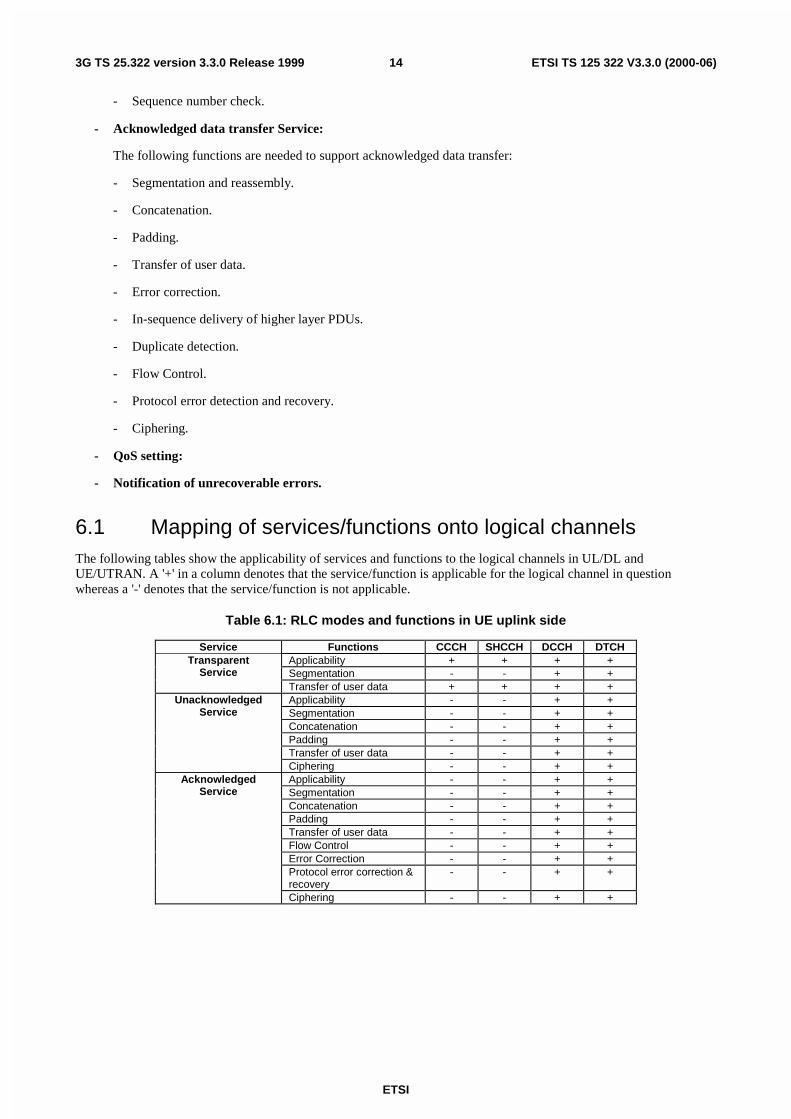
6.1 Mapping of services/functions onto logical channelsThe following tables show the applicability of services and functions to the logical channels in UL/DL andUE/UTRAN. A '+' in a column denotes that the service/function is applicable for the logical channel in questionwhereas a '-' denotes that the service/function is not applicable.
Table 6.1: RLC modes and functions in UE uplink side
Service Functions CCCH SHCCH DCCH DTCHApplicability + + + +Segmentation - - + +
TransparentService
Transfer of user data + + + +Applicability - - + +Segmentation - - + +Concatenation - - + +Padding - - + +Transfer of user data - - + +
UnacknowledgedService
Ciphering - - + +Applicability - - + +Segmentation - - + +Concatenation - - + +Padding - - + +Transfer of user data - - + +Flow Control - - + +Error Correction - - + +Protocol error correction &recovery
- - + +
AcknowledgedService
Ciphering - - + +
ETSI
ETSI TS 125 322 V3.3.0 (2000-06)153G TS 25.322 version 3.3.0 Release 1999
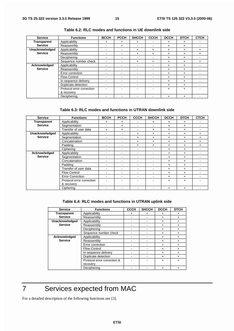
Table 6.2: RLC modes and functions in UE downlink side
Service Functions BCCH PCCH SHCCH CCCH DCCH DTCH CTCHApplicability + + + - + + -Transparent
Service Reassembly - + - - + + -Applicability - - + + + + +Reassembly - - + + + + +Deciphering - - - - + + -
UnacknowledgedService
Sequence number check - - + + + + +Applicability - - - - + + -Reassembly - - - - + + -Error correction - - - - + + -Flow Control - - - - + + -In sequence delivery - - - - + + -Duplicate detection - - - - + + -Protocol error correction& recovery
- - - - + + -
AcknowledgedService
Deciphering - - - - + + -
Table 6.3: RLC modes and functions in UTRAN downlink side
Service Functions BCCH PCCH CCCH SHCCH DCCH DTCH CTCHApplicability + + - + + + -Segmentation - + - - + + -
TransparentService
Transfer of user data + + - + + + -Applicability - - + + + + +Segmentation - - + + + + +Concatenation - - + + + + +Padding - - + + + + +
UnacknowledgedService
Ciphering - - - - + + -Applicability - - - - + + -Segmentation - - - - + + -Concatenation - - - - + + -Padding - - - - + + -Transfer of user data - - - - + + -Flow Control - - - - + + -Error Correction - - - - + + -Protocol error correction& recovery
- - - - + + -
AcknowledgedService
Ciphering - - - - + + -
Table 6.4: RLC modes and functions in UTRAN uplink side
Service Functions CCCH SHCCH DCCH DTCHApplicability + + + +Transparent
Service Reassembly - - + +Applicability - - + +Reassembly - - + +Deciphering - - + +
UnacknowledgedService
Sequence number check - - + +Applicability - - + +Reassembly - - + +Error correction - - + +Flow Control - - + +In sequence delivery - - + +Duplicate detection - - + +Protocol error correction &recovery
- - + +
AcknowledgedService
Deciphering - - + +
7 Services expected from MACFor a detailed description of the following functions see [3].
ETSI
ETSI TS 125 322 V3.3.0 (2000-06)163G TS 25.322 version 3.3.0 Release 1999
- Data transfer.
8 Elements for layer-to-layer communicationThe interaction between the RLC layer and other layers are described in terms of primitives where the primitivesrepresent the logical exchange of information and control between the RLC layer and other layers. The primitives shallnot specify or constrain implementations.
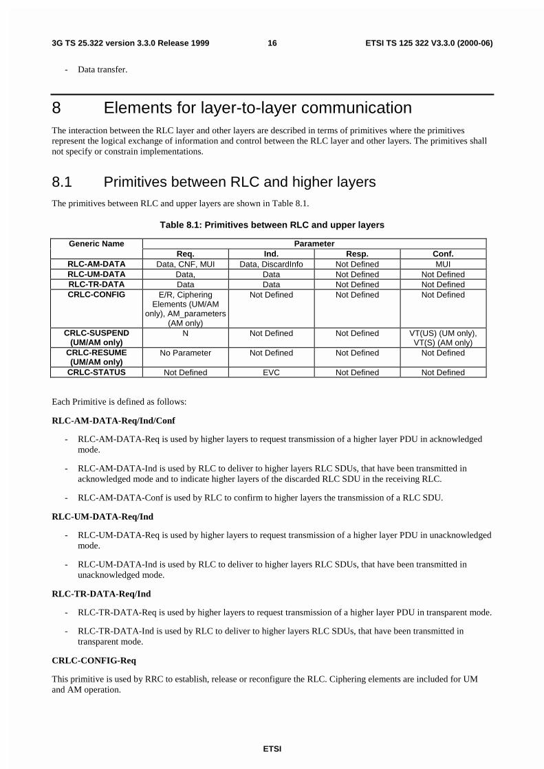
8.1 Primitives between RLC and higher layersThe primitives between RLC and upper layers are shown in Table 8.1.
Table 8.1: Primitives between RLC and upper layers
Generic Name ParameterReq. Ind. Resp. Conf.
RLC-AM-DATA Data, CNF, MUI Data, DiscardInfo Not Defined MUIRLC-UM-DATA Data, Data Not Defined Not DefinedRLC-TR-DATA Data Data Not Defined Not DefinedCRLC-CONFIG E/R, Ciphering
Elements (UM/AMonly), AM_parameters
(AM only)
Not Defined Not Defined Not Defined
CRLC-SUSPEND(UM/AM only)
N Not Defined Not Defined VT(US) (UM only),VT(S) (AM only)
CRLC-RESUME(UM/AM only)
No Parameter Not Defined Not Defined Not Defined
CRLC-STATUS Not Defined EVC Not Defined Not Defined
Each Primitive is defined as follows:
RLC-AM-DATA-Req/Ind/Conf
- RLC-AM-DATA-Req is used by higher layers to request transmission of a higher layer PDU in acknowledgedmode.
- RLC-AM-DATA-Ind is used by RLC to deliver to higher layers RLC SDUs, that have been transmitted inacknowledged mode and to indicate higher layers of the discarded RLC SDU in the receiving RLC.
- RLC-AM-DATA-Conf is used by RLC to confirm to higher layers the transmission of a RLC SDU.
RLC-UM-DATA-Req/Ind
- RLC-UM-DATA-Req is used by higher layers to request transmission of a higher layer PDU in unacknowledgedmode.
- RLC-UM-DATA-Ind is used by RLC to deliver to higher layers RLC SDUs, that have been transmitted inunacknowledged mode.
RLC-TR-DATA-Req/Ind
- RLC-TR-DATA-Req is used by higher layers to request transmission of a higher layer PDU in transparent mode.
- RLC-TR-DATA-Ind is used by RLC to deliver to higher layers RLC SDUs, that have been transmitted intransparent mode.
CRLC-CONFIG-Req
This primitive is used by RRC to establish, release or reconfigure the RLC. Ciphering elements are included for UMand AM operation.
ETSI
ETSI TS 125 322 V3.3.0 (2000-06)173G TS 25.322 version 3.3.0 Release 1999
CRLC-SUSPEND-Req/Conf
This primitive is used by RRC to suspend the RLC. The N parameter indicates that RLC shall not send a PDU withSN>=VT(S)+N, where N is an integer. RLC informs RRC of the VT(S) value in the confirm primitive.
CRLC-RESUME-Req
This primitive is used by RRC to resume RLC when RLC has been suspended.
CRLC-STATUS-Ind
It is used by the RLC to send status information to RRC.
Following parameters are used in the primitives:
1) The parameter Data is the RLC SDU that is mapped onto the Data field in RLC PDUs. The Data parameter maybe divided over several RLC PDUs. In case of a RLC-AM-DATA or a RLC-UM-DATA primitive the length ofthe Data parameter shall be octet-aligned.
2) The parameter Confirmation request (CNF) indicates whether the RLC needs to confirm the correct transmissionof the RLC SDU.
3) The parameter Message Unit Identifier (MUI) is an identity of the RLC SDU, which is used to indicate whichRLC SDU that is confirmed with the RLC-AM-DATA conf. primitive.
4) The parameter E/R indicates (re)establishment, release or modification of RLC If it indicates (re)establishment,all protocol parameters, variables and timers shall be set or reset and RLC shall enter the data transfer readystate. If it indicates release, all protocol parameters, variables and timers shall be released and RLC shall exit thedata transfer ready state. If it indicates modification, the protocol parameters indicated by RRC (e.g. cipheringparameters) shall only be modified with keeping the other protocol parameters, the protocol variables, theprotocol timers and the protocol state.
5) The parameter Event Code (EVC) indicates the reason for the CRLC-STATUS-ind (i.e., unrecoverable errorssuch as data link layer loss or recoverable status events such as reset, etc.).
6) The parameter ciphering elements are only applicable for UM and AM operation. These parameters areCiphering Mode, Ciphering Key, Activation Time (SN to activate a new ciphering configuration) and HFN(Hyper Frame Number).
7) The AM_parameters is only applicable for AM operation. It contains PU size, Timer values (see subclause 9.5),Protocol parameter values (see subclause 9.6), Polling triggers (see subclause 9.7.1), Status triggers (seesubclause 9.7.2), SDU discard mode (see subclause 9.7.3).
8) The parameter DiscardInfo indicates the upper layer of each of the discarded RLC SDU. It is applicable onlywhen in-sequence delivery is active and it is purposed to be used when the upper layer requires the reliable datatransfer and especially the information of the discarded RLC SDU.
9 Elements for peer-to-peer communication
9.1 Protocol data units
9.1.1 Data PDUs
a) TrD PDU (Transparent Mode Data PDU).
The TrD PDU is used to convey RLC SDU data without adding any RLC overhead. The TrD PDU is used byRLC when it is in transparent mode.
b) UMD PDU (Unacknowledged Mode Data PDU).
The UMD PDU is used to convey sequentially numbered PDUs containing RLC SDU data. It is used by RLCwhen using unacknowledged data transfer.
ETSI
ETSI TS 125 322 V3.3.0 (2000-06)183G TS 25.322 version 3.3.0 Release 1999
c) AMD PDU (Acknowledged Mode Data PDU).
The AMD PDU is used to convey sequentially numbered PUs containing RLC SDU data. The AMD PDU isused by RLC when it is in acknowledged mode.
9.1.2 Control PDUs
a) STATUS PDU and Piggybacked STATUS PDU
The STATUS PDU and the Piggybacked STATUS PDU are used:
- by the receiving entity to inform the transmitting entity about missing PUs at the receiving entity;
- by the receiving entity to inform the transmitting entity about the size of the allowed transmission window;
- and by the transmitting entity to request the receiving entity to move the receiving window.
b) RESET PDU
The RESET PDU is used in acknowledged mode to reset all protocol states, protocol variables and protocoltimers of the peer RLC entity in order to synchronise the two peer entities.
c) RESET ACK PDU
The RESET ACK PDU is an acknowledgement to the RESET PDU.
Table 9.1: RLC PDU names and descriptions
Data Transfer Mode PDU name DescriptionTransparent TrD Transparent mode data
Unacknowledged UMD Sequenced unacknowledged mode dataAMD Sequenced acknowledged mode dataSTATUS Solicited or Unsolicited Status ReportPiggybackedSTATUS
Piggybacked Solicited or Unsolicited Status Report
RESET Reset Command
Acknowledged
RESET ACK Reset Acknowledgement
9.2 Formats and parameters
9.2.1 Formats
This subclause specifies the format of the RLC PDUs. The parameters of each PDU are explained in subclause 9.2.2.
9.2.1.1 General
An RLC PDU is a bit string, with a length not necessarily a multiple of 8 bits. In the drawings in clause 9.2, bit stringsare represented by tables in which the first bit is the leftmost one on the first line of the table, the last bit is the rightmoston the last line of the table, and more generally the bit string is to be read from left to right and then in the reading orderof the lines.
Depending on the provided service, RLC SDUs are bit strings, with any nonnull length, or bit strings with an integernumber of octets in length. An SDU is included into an RLC PDU from first bit onward.
9.2.1.2 TrD PDU
The TrD PDU transfers user data when RLC is operating in transparent mode. No overhead is added to the SDU byRLC. The data length is not constrained to be an integer number of octets.
ETSI
ETSI TS 125 322 V3.3.0 (2000-06)193G TS 25.322 version 3.3.0 Release 1999
Data
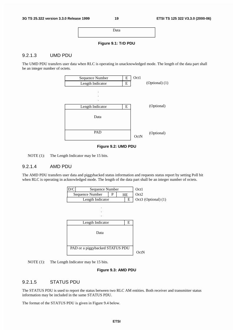
Figure 9.1: TrD PDU
9.2.1.3 UMD PDU
The UMD PDU transfers user data when RLC is operating in unacknowledged mode. The length of the data part shallbe an integer number of octets.
Oct1
ELength Indicator
Data
PADOctN
ELength Indicator (Optional) (1)
.
.
.
ESequence Number
(Optional)
(Optional)
Figure 9.2: UMD PDU
NOTE (1): The Length Indicator may be 15 bits.
9.2.1.4 AMD PDU
The AMD PDU transfers user data and piggybacked status information and requests status report by setting Poll bitwhen RLC is operating in acknowledged mode. The length of the data part shall be an integer number of octets.
Sequence NumberSequence Number
D/C
ELength Indicator
Data
PAD or a piggybacked STATUS PDU
Oct1Oct2
OctN
P HEELength Indicator
.
.
.
(Optional) (1)Oct3
NOTE (1): The Length Indicator may be 15 bits.
Figure 9.3: AMD PDU
9.2.1.5 STATUS PDU
The STATUS PDU is used to report the status between two RLC AM entities. Both receiver and transmitter statusinformation may be included in the same STATUS PDU.
The format of the STATUS PDU is given in Figure 9.4 below.
ETSI
ETSI TS 125 322 V3.3.0 (2000-06)203G TS 25.322 version 3.3.0 Release 1999
D/C PDU type SUFI 1 Oct 1
Oct2
OctN
…
SUFIK
SUFI1
PAD
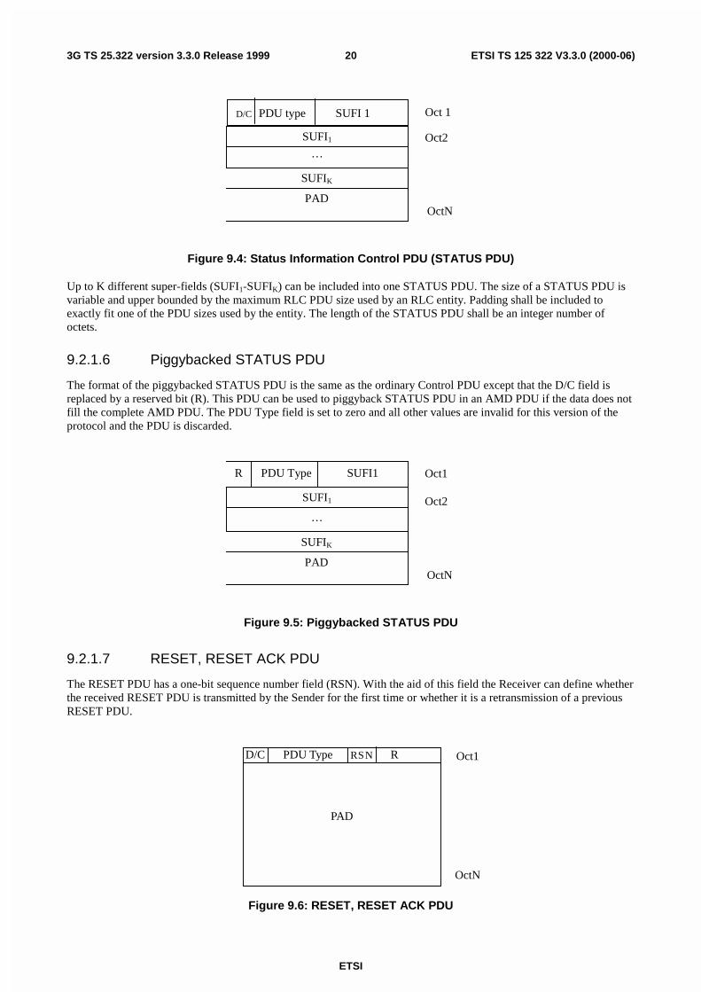
Figure 9.4: Status Information Control PDU (STATUS PDU)
Up to K different super-fields (SUFI1-SUFIK) can be included into one STATUS PDU. The size of a STATUS PDU isvariable and upper bounded by the maximum RLC PDU size used by an RLC entity. Padding shall be included toexactly fit one of the PDU sizes used by the entity. The length of the STATUS PDU shall be an integer number ofoctets.
9.2.1.6 Piggybacked STATUS PDU
The format of the piggybacked STATUS PDU is the same as the ordinary Control PDU except that the D/C field isreplaced by a reserved bit (R). This PDU can be used to piggyback STATUS PDU in an AMD PDU if the data does notfill the complete AMD PDU. The PDU Type field is set to zero and all other values are invalid for this version of theprotocol and the PDU is discarded.
Oct1
Oct2
OctN
…
SUFIK
SUFI1
PAD
R PDU Type SUFI1
Figure 9.5: Piggybacked STATUS PDU
9.2.1.7 RESET, RESET ACK PDU
The RESET PDU has a one-bit sequence number field (RSN). With the aid of this field the Receiver can define whetherthe received RESET PDU is transmitted by the Sender for the first time or whether it is a retransmission of a previousRESET PDU.
Oct1
OctN
D/C RPDU Type
PAD
RSN
Figure 9.6: RESET, RESET ACK PDU
ETSI
ETSI TS 125 322 V3.3.0 (2000-06)213G TS 25.322 version 3.3.0 Release 1999
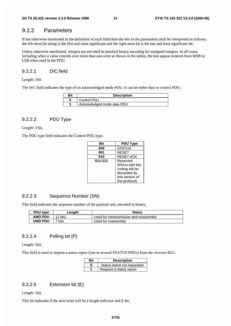
9.2.2 Parameters
If not otherwise mentioned in the definition of each field then the bits in the parameters shall be interpreted as follows:the left-most bit string is the first and most significant and the right most bit is the last and least significant bit.
Unless otherwise mentioned, integers are encoded in standard binary encoding for unsigned integers. In all cases,including when a value extends over more than one octet as shown in the tables, the bits appear ordered from MSB toLSB when read in the PDU.
9.2.2.1 D/C field
Length: 1bit.
The D/C field indicates the type of an acknowledged mode PDU. It can be either data or control PDU.
Bit Description0 Control PDU1 Acknowledged mode data PDU
9.2.2.2 PDU Type
Length: 3 bit.
The PDU type field indicates the Control PDU type.
Bit PDU Type000 STATUS001 RESET010 RESET ACK
011-111 Reserved(PDUs with thiscoding will bediscarded bythis version ofthe protocol).
9.2.2.3 Sequence Number (SN)
This field indicates the sequence number of the payload unit, encoded in binary.
PDU type Length NotesAMD PDU 12 bits Used for retransmission and reassemblyUMD PDU 7 bits Used for reassembly
9.2.2.4 Polling bit (P)
Length: 1bit.
This field is used to request a status report (one or several STATUS PDUs) from the receiver RLC.
Bit Description0 Status report not requested1 Request a status report
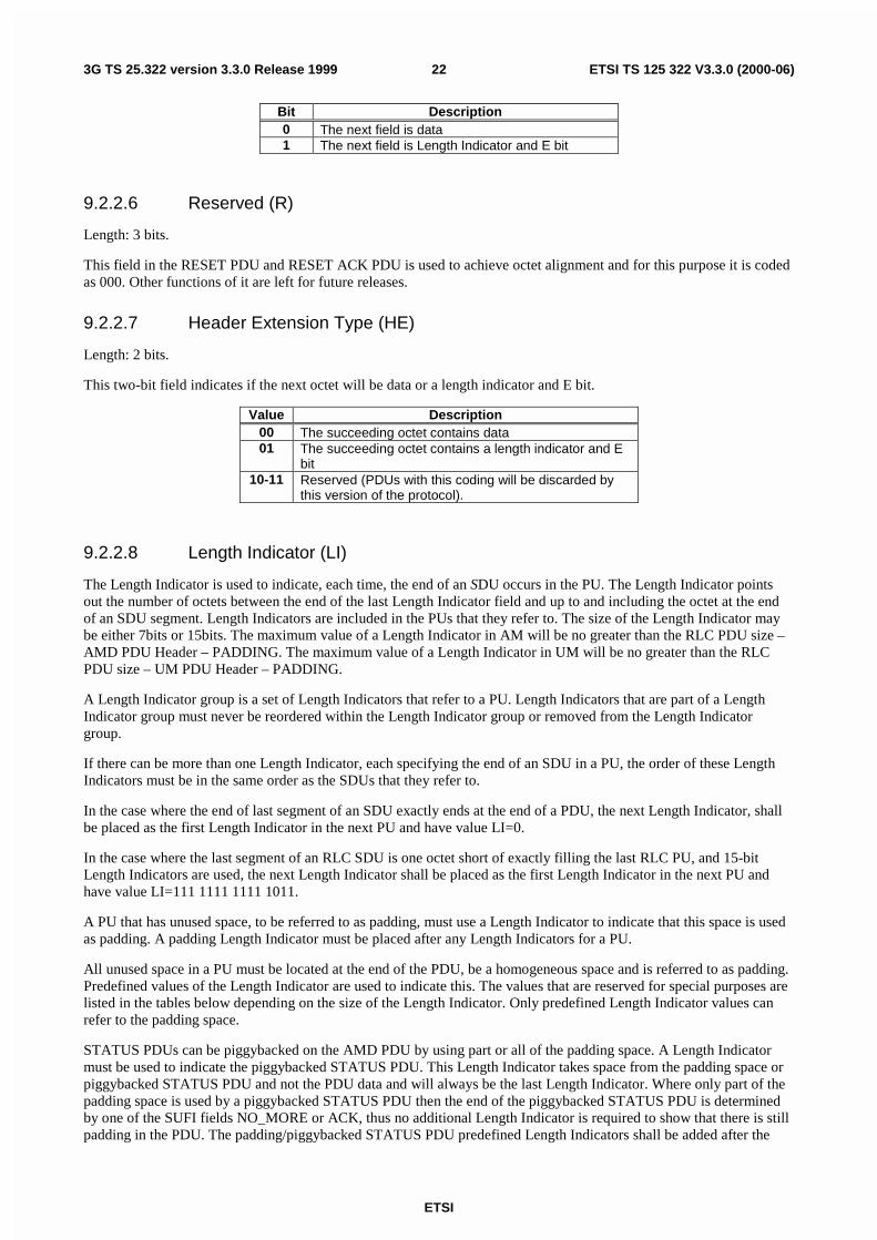
9.2.2.5 Extension bit (E)
Length: 1bit.
This bit indicates if the next octet will be a length indicator and E bit.
ETSI
ETSI TS 125 322 V3.3.0 (2000-06)223G TS 25.322 version 3.3.0 Release 1999
Bit Description0 The next field is data1 The next field is Length Indicator and E bit
9.2.2.6 Reserved (R)
Length: 3 bits.
This field in the RESET PDU and RESET ACK PDU is used to achieve octet alignment and for this purpose it is codedas 000. Other functions of it are left for future releases.
9.2.2.7 Header Extension Type (HE)
Length: 2 bits.
This two-bit field indicates if the next octet will be data or a length indicator and E bit.
Value Description00 The succeeding octet contains data01 The succeeding octet contains a length indicator and E
bit10-11 Reserved (PDUs with this coding will be discarded by
this version of the protocol).
9.2.2.8 Length Indicator (LI)
The Length Indicator is used to indicate, each time, the end of an SDU occurs in the PU. The Length Indicator pointsout the number of octets between the end of the last Length Indicator field and up to and including the octet at the endof an SDU segment. Length Indicators are included in the PUs that they refer to. The size of the Length Indicator maybe either 7bits or 15bits. The maximum value of a Length Indicator in AM will be no greater than the RLC PDU size –AMD PDU Header – PADDING. The maximum value of a Length Indicator in UM will be no greater than the RLCPDU size – UM PDU Header – PADDING.
A Length Indicator group is a set of Length Indicators that refer to a PU. Length Indicators that are part of a LengthIndicator group must never be reordered within the Length Indicator group or removed from the Length Indicatorgroup.
If there can be more than one Length Indicator, each specifying the end of an SDU in a PU, the order of these LengthIndicators must be in the same order as the SDUs that they refer to.
In the case where the end of last segment of an SDU exactly ends at the end of a PDU, the next Length Indicator, shallbe placed as the first Length Indicator in the next PU and have value LI=0.
In the case where the last segment of an RLC SDU is one octet short of exactly filling the last RLC PU, and 15-bitLength Indicators are used, the next Length Indicator shall be placed as the first Length Indicator in the next PU andhave value LI=111 1111 1111 1011.
A PU that has unused space, to be referred to as padding, must use a Length Indicator to indicate that this space is usedas padding. A padding Length Indicator must be placed after any Length Indicators for a PU.
All unused space in a PU must be located at the end of the PDU, be a homogeneous space and is referred to as padding.Predefined values of the Length Indicator are used to indicate this. The values that are reserved for special purposes arelisted in the tables below depending on the size of the Length Indicator. Only predefined Length Indicator values canrefer to the padding space.
STATUS PDUs can be piggybacked on the AMD PDU by using part or all of the padding space. A Length Indicatormust be used to indicate the piggybacked STATUS PDU. This Length Indicator takes space from the padding space orpiggybacked STATUS PDU and not the PDU data and will always be the last Length Indicator. Where only part of thepadding space is used by a piggybacked STATUS PDU then the end of the piggybacked STATUS PDU is determinedby one of the SUFI fields NO_MORE or ACK, thus no additional Length Indicator is required to show that there is stillpadding in the PDU. The padding/piggybacked STATUS PDU predefined Length Indicators shall be added after the
ETSI
ETSI TS 125 322 V3.3.0 (2000-06)233G TS 25.322 version 3.3.0 Release 1999
very last (i.e. there could be more than one SDU that end within a PDU) Length Indicator that indicates the end of thelast SDU segment in the PU.
For AM, 7bit indicators shall be used if the AMD PDU size is ≤ l26 octets. Otherwise 15bit indicators shall be used. ForUM, 7bit indicators shall be used if the UM PDU size is ≤ l25 octets. Otherwise 15bit indicators shall be used.
The length of the Length Indicator only depends on the size of the largest RLC PDU. The length of the Length Indicatoris always the same for all PUs, for one RLC entity.
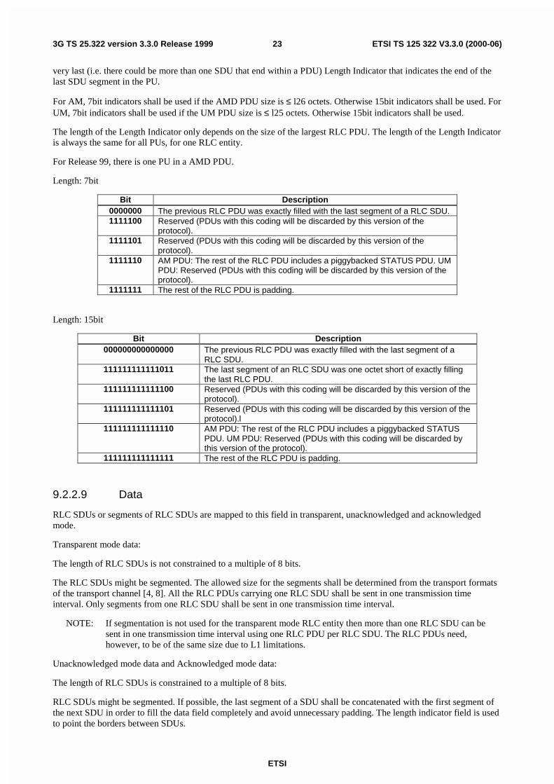
For Release 99, there is one PU in a AMD PDU.
Length: 7bit
Bit Description0000000 The previous RLC PDU was exactly filled with the last segment of a RLC SDU.1111100 Reserved (PDUs with this coding will be discarded by this version of the
protocol).1111101 Reserved (PDUs with this coding will be discarded by this version of the
protocol).1111110 AM PDU: The rest of the RLC PDU includes a piggybacked STATUS PDU. UM
PDU: Reserved (PDUs with this coding will be discarded by this version of theprotocol).
1111111 The rest of the RLC PDU is padding.
Length: 15bit
Bit Description000000000000000 The previous RLC PDU was exactly filled with the last segment of a
RLC SDU.111111111111011 The last segment of an RLC SDU was one octet short of exactly filling
the last RLC PDU.111111111111100 Reserved (PDUs with this coding will be discarded by this version of the
protocol).111111111111101 Reserved (PDUs with this coding will be discarded by this version of the
protocol).l111111111111110 AM PDU: The rest of the RLC PDU includes a piggybacked STATUS
PDU. UM PDU: Reserved (PDUs with this coding will be discarded bythis version of the protocol).
111111111111111 The rest of the RLC PDU is padding.
9.2.2.9 Data
RLC SDUs or segments of RLC SDUs are mapped to this field in transparent, unacknowledged and acknowledgedmode.
Transparent mode data:
The length of RLC SDUs is not constrained to a multiple of 8 bits.
The RLC SDUs might be segmented. The allowed size for the segments shall be determined from the transport formatsof the transport channel [4, 8]. All the RLC PDUs carrying one RLC SDU shall be sent in one transmission timeinterval. Only segments from one RLC SDU shall be sent in one transmission time interval.
NOTE: If segmentation is not used for the transparent mode RLC entity then more than one RLC SDU can besent in one transmission time interval using one RLC PDU per RLC SDU. The RLC PDUs need,however, to be of the same size due to L1 limitations.
Unacknowledged mode data and Acknowledged mode data:
The length of RLC SDUs is constrained to a multiple of 8 bits.
RLC SDUs might be segmented. If possible, the last segment of a SDU shall be concatenated with the first segment ofthe next SDU in order to fill the data field completely and avoid unnecessary padding. The length indicator field is usedto point the borders between SDUs.
ETSI
ETSI TS 125 322 V3.3.0 (2000-06)243G TS 25.322 version 3.3.0 Release 1999
9.2.2.10 Padding (PAD)
Padding has a length such that the PDU has the required predefined total length.
Padding may have any value and the receiving entity shall disregard it.
9.2.2.11 SUFI
Which SUFI fields to use is implementation dependent, but when a STATUS PDU includes information about whichPUs have been received and which are detected as missing, information shall not be included about PUs withSN≥VR(H) i.e. PUs that have not yet reached the receiver. Information about PUs with SN<VR(R) shall not be givenexcept when this is necessary in order to use the BITMAP SUFI, see 9.2.2.11.5.
Length: variable number of bits.
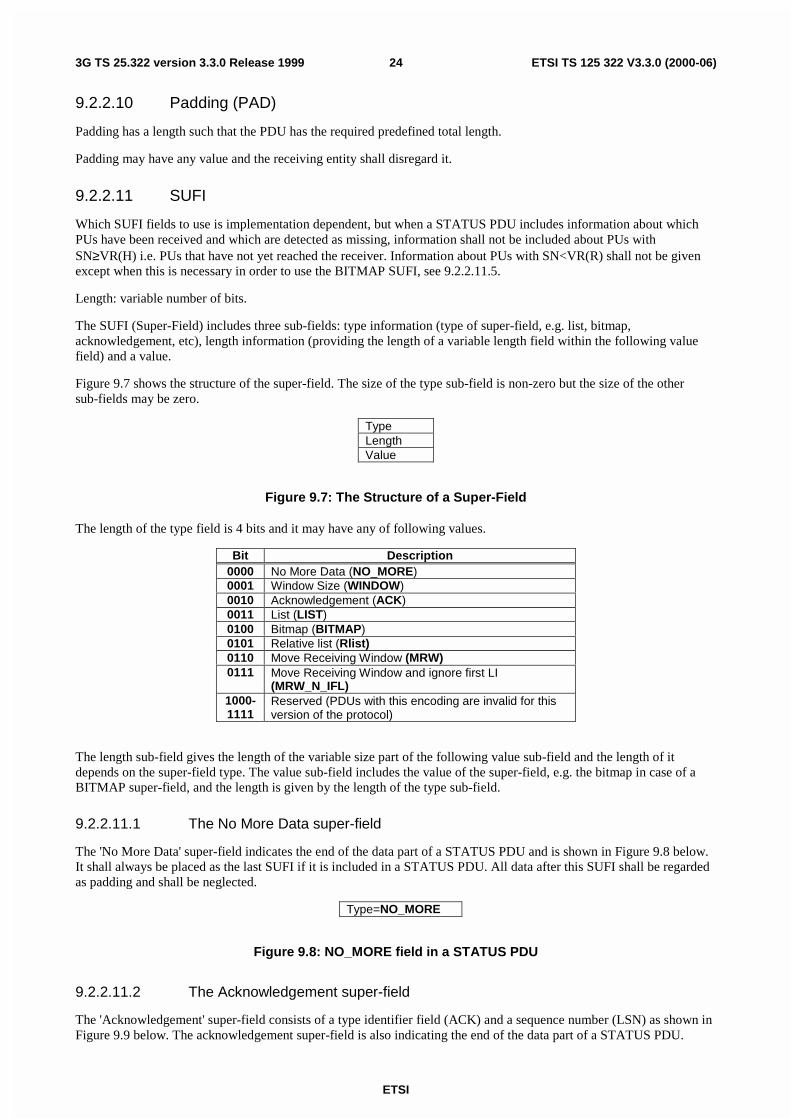
The SUFI (Super-Field) includes three sub-fields: type information (type of super-field, e.g. list, bitmap,acknowledgement, etc), length information (providing the length of a variable length field within the following valuefield) and a value.
Figure 9.7 shows the structure of the super-field. The size of the type sub-field is non-zero but the size of the othersub-fields may be zero.
TypeLengthValue
Figure 9.7: The Structure of a Super-Field
The length of the type field is 4 bits and it may have any of following values.
Bit Description0000 No More Data (NO_MORE)0001 Window Size (WINDOW)0010 Acknowledgement (ACK)0011 List (LIST)0100 Bitmap (BITMAP)0101 Relative list (Rlist)0110 Move Receiving Window (MRW)0111 Move Receiving Window and ignore first LI
(MRW_N_IFL)1000-1111
Reserved (PDUs with this encoding are invalid for thisversion of the protocol)
The length sub-field gives the length of the variable size part of the following value sub-field and the length of itdepends on the super-field type. The value sub-field includes the value of the super-field, e.g. the bitmap in case of aBITMAP super-field, and the length is given by the length of the type sub-field.
9.2.2.11.1 The No More Data super-field
The 'No More Data' super-field indicates the end of the data part of a STATUS PDU and is shown in Figure 9.8 below.It shall always be placed as the last SUFI if it is included in a STATUS PDU. All data after this SUFI shall be regardedas padding and shall be neglected.
Type=NO_MORE
Figure 9.8: NO_MORE field in a STATUS PDU
9.2.2.11.2 The Acknowledgement super-field
The 'Acknowledgement' super-field consists of a type identifier field (ACK) and a sequence number (LSN) as shown inFigure 9.9 below. The acknowledgement super-field is also indicating the end of the data part of a STATUS PDU.
ETSI
ETSI TS 125 322 V3.3.0 (2000-06)253G TS 25.322 version 3.3.0 Release 1999
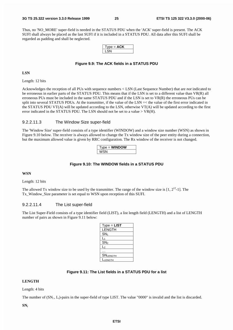
Thus, no 'NO_MORE' super-field is needed in the STATUS PDU when the 'ACK' super-field is present. The ACKSUFI shall always be placed as the last SUFI if it is included in a STATUS PDU. All data after this SUFI shall beregarded as padding and shall be neglected.
Type = ACKLSN
Figure 9.9: The ACK fields in a STATUS PDU
LSN
Length: 12 bits
Acknowledges the reception of all PUs with sequence numbers < LSN (Last Sequence Number) that are not indicated tobe erroneous in earlier parts of the STATUS PDU. This means that if the LSN is set to a different value than VR(R) allerroneous PUs must be included in the same STATUS PDU and if the LSN is set to VR(R) the erroneous PUs can besplit into several STATUS PDUs. At the transmitter, if the value of the LSN =< the value of the first error indicated inthe STATUS PDU VT(A) will be updated according to the LSN, otherwise VT(A) will be updated according to the firsterror indicated in the STATUS PDU. The LSN should not be set to a value > VR(H).
9.2.2.11.3 The Window Size super-field
The 'Window Size' super-field consists of a type identifier (WINDOW) and a window size number (WSN) as shown inFigure 9.10 below. The receiver is always allowed to change the Tx window size of the peer entity during a connection,but the maximum allowed value is given by RRC configuration. The Rx window of the receiver is not changed.
Type = WINDOWWSN
Figure 9.10: The WINDOW fields in a STATUS PDU
WSN
Length: 12 bits
The allowed Tx window size to be used by the transmitter. The range of the window size is [1, 212-1]. TheTx_Window_Size parameter is set equal to WSN upon reception of this SUFI.
9.2.2.11.4 The List super-field
The List Super-Field consists of a type identifier field (LIST), a list length field (LENGTH) and a list of LENGTHnumber of pairs as shown in Figure 9.11 below:
Type = LISTLENGTHSN1
L1
SN2
L2
…SNLENGTH
LLENGTH
Figure 9.11: The List fields in a STATUS PDU for a list
LENGTH
Length: 4 bits
The number of (SNi , Li)-pairs in the super-field of type LIST. The value "0000" is invalid and the list is discarded.
SNi
ETSI
ETSI TS 125 322 V3.3.0 (2000-06)263G TS 25.322 version 3.3.0 Release 1999
Length: 12 bits
Sequence number of PU, which was not correctly received.
Li
Length: 4 bits
Number of consecutive PUs not correctly received following PU with sequence number SNi.
9.2.2.11.5 The Bitmap super-field
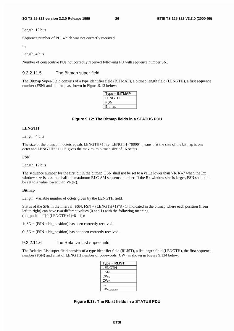
The Bitmap Super-Field consists of a type identifier field (BITMAP), a bitmap length field (LENGTH), a first sequencenumber (FSN) and a bitmap as shown in Figure 9.12 below:
Type = BITMAPLENGTHFSNBitmap
Figure 9.12: The Bitmap fields in a STATUS PDU
LENGTH
Length: 4 bits
The size of the bitmap in octets equals LENGTH+1, i.e. LENGTH="0000" means that the size of the bitmap is oneoctet and LENGTH="1111" gives the maximum bitmap size of 16 octets.
FSN
Length: 12 bits
The sequence number for the first bit in the bitmap. FSN shall not be set to a value lower than VR(R)-7 when the Rxwindow size is less then half the maximum RLC AM sequence number. If the Rx window size is larger, FSN shall notbe set to a value lower than VR(R).
Bitmap
Length: Variable number of octets given by the LENGTH field.
Status of the SNs in the interval [FSN, FSN + (LENGTH+1)*8 - 1] indicated in the bitmap where each position (fromleft to right) can have two different values (0 and 1) with the following meaning(bit_position∈ [0,(LENGTH+1)*8 - 1]):
1: SN = (FSN + bit_position) has been correctly received.
0: SN = (FSN + bit_position) has not been correctly received.
9.2.2.11.6 The Relative List super-field
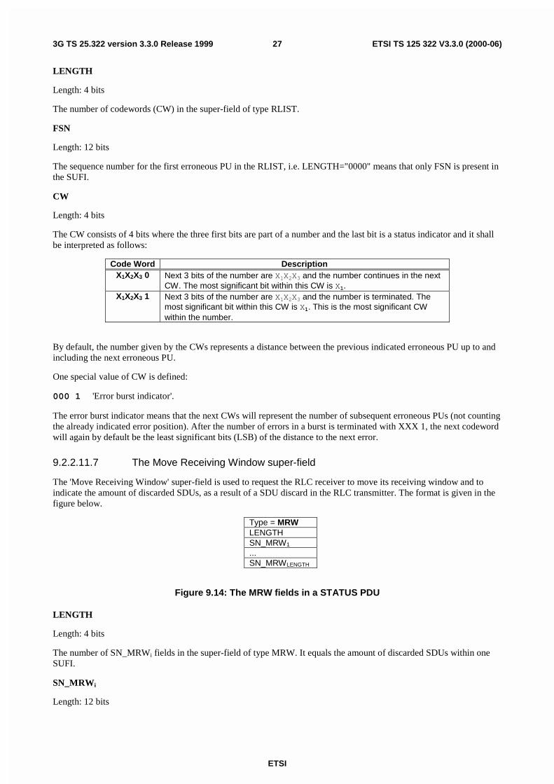
The Relative List super-field consists of a type identifier field (RLIST), a list length field (LENGTH), the first sequencenumber (FSN) and a list of LENGTH number of codewords (CW) as shown in Figure 9.134 below.
Type = RLISTLENGTHFSNCW1
CW2
…CWLENGTH
Figure 9.13: The RList fields in a STATUS PDU
ETSI
ETSI TS 125 322 V3.3.0 (2000-06)273G TS 25.322 version 3.3.0 Release 1999
LENGTH
Length: 4 bits
The number of codewords (CW) in the super-field of type RLIST.
FSN
Length: 12 bits
The sequence number for the first erroneous PU in the RLIST, i.e. LENGTH="0000" means that only FSN is present inthe SUFI.
CW
Length: 4 bits
The CW consists of 4 bits where the three first bits are part of a number and the last bit is a status indicator and it shallbe interpreted as follows:
Code Word DescriptionX1X2X3 0 Next 3 bits of the number are X1X2X3 and the number continues in the next
CW. The most significant bit within this CW is X1.X1X2X3 1 Next 3 bits of the number are X1X2X3 and the number is terminated. The
most significant bit within this CW is X1. This is the most significant CWwithin the number.
By default, the number given by the CWs represents a distance between the previous indicated erroneous PU up to andincluding the next erroneous PU.
One special value of CW is defined:
000 1 'Error burst indicator'.
The error burst indicator means that the next CWs will represent the number of subsequent erroneous PUs (not countingthe already indicated error position). After the number of errors in a burst is terminated with XXX 1, the next codewordwill again by default be the least significant bits (LSB) of the distance to the next error.
9.2.2.11.7 The Move Receiving Window super-field
The 'Move Receiving Window' super-field is used to request the RLC receiver to move its receiving window and toindicate the amount of discarded SDUs, as a result of a SDU discard in the RLC transmitter. The format is given in thefigure below.
Type = MRWLENGTHSN_MRW1
...SN_MRWLENGTH
Figure 9.14: The MRW fields in a STATUS PDU
LENGTH
Length: 4 bits
The number of SN_MRWi fields in the super-field of type MRW. It equals the amount of discarded SDUs within oneSUFI.
SN_MRWi
Length: 12 bits
ETSI
ETSI TS 125 322 V3.3.0 (2000-06)283G TS 25.322 version 3.3.0 Release 1999
SN_MRWi fields enumerate each of the discarded SDUs by indicating the sequence number of the PU in which thesucceeding SDU of the i:th discarded SDU begins.
Additionally SN_MRWLENGTH requests the RLC receiver to discard all PUs with sequence number < SN_MRWLENGTH,and to move the receiving window accordingly. It also indicates the first data byte in the PU with sequence numberSN_MRWLENGTH corresponds to the first byte of the SDU to be reassembled next.
9.2.2.11.8 The Move Receiving Window and Ignore First LI (MRW_N_IFL) super-field
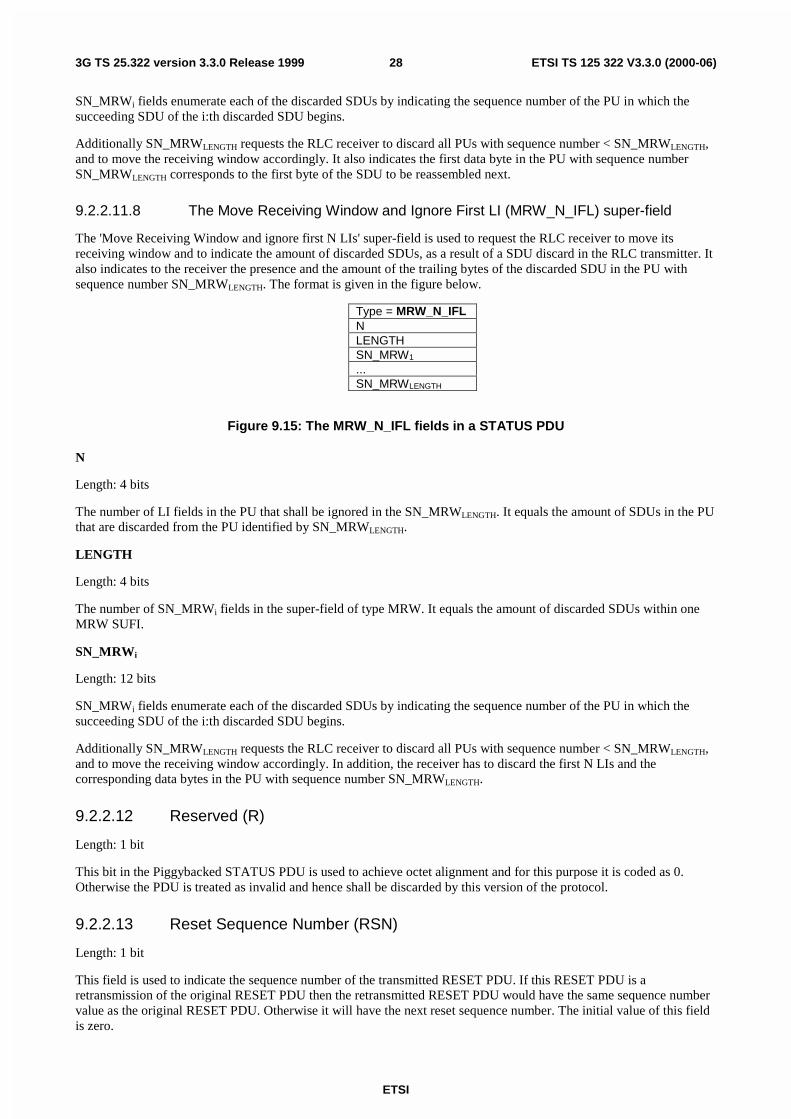
The 'Move Receiving Window and ignore first N LIs' super-field is used to request the RLC receiver to move itsreceiving window and to indicate the amount of discarded SDUs, as a result of a SDU discard in the RLC transmitter. Italso indicates to the receiver the presence and the amount of the trailing bytes of the discarded SDU in the PU withsequence number SN_MRWLENGTH. The format is given in the figure below.
Type = MRW_N_IFLNLENGTHSN_MRW1
...SN_MRWLENGTH
Figure 9.15: The MRW_N_IFL fields in a STATUS PDU
N
Length: 4 bits
The number of LI fields in the PU that shall be ignored in the SN_MRWLENGTH. It equals the amount of SDUs in the PUthat are discarded from the PU identified by SN_MRWLENGTH.
LENGTH
Length: 4 bits
The number of SN_MRWi fields in the super-field of type MRW. It equals the amount of discarded SDUs within oneMRW SUFI.
SN_MRWi
Length: 12 bits
SN_MRWi fields enumerate each of the discarded SDUs by indicating the sequence number of the PU in which thesucceeding SDU of the i:th discarded SDU begins.
Additionally SN_MRWLENGTH requests the RLC receiver to discard all PUs with sequence number < SN_MRWLENGTH,and to move the receiving window accordingly. In addition, the receiver has to discard the first N LIs and thecorresponding data bytes in the PU with sequence number SN_MRWLENGTH.
9.2.2.12 Reserved (R)
Length: 1 bit
This bit in the Piggybacked STATUS PDU is used to achieve octet alignment and for this purpose it is coded as 0.Otherwise the PDU is treated as invalid and hence shall be discarded by this version of the protocol.
9.2.2.13 Reset Sequence Number (RSN)
Length: 1 bit
This field is used to indicate the sequence number of the transmitted RESET PDU. If this RESET PDU is aretransmission of the original RESET PDU then the retransmitted RESET PDU would have the same sequence numbervalue as the original RESET PDU. Otherwise it will have the next reset sequence number. The initial value of this fieldis zero.
ETSI
ETSI TS 125 322 V3.3.0 (2000-06)293G TS 25.322 version 3.3.0 Release 1999
9.3 Protocol states
9.3.1 State model for transparent mode entities
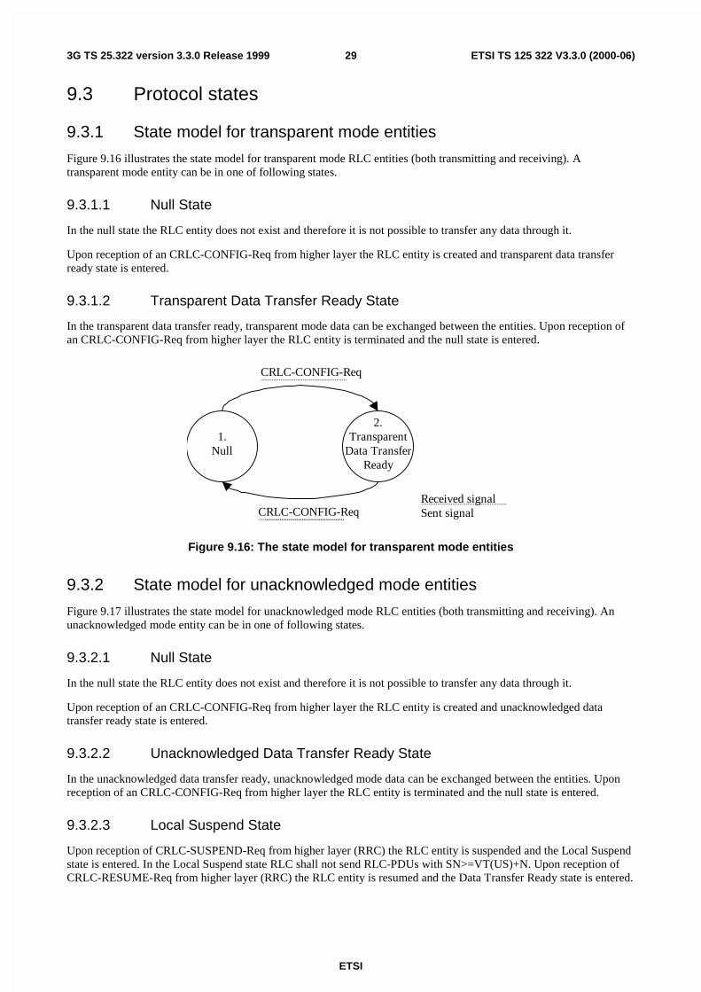
Figure 9.16 illustrates the state model for transparent mode RLC entities (both transmitting and receiving). Atransparent mode entity can be in one of following states.
9.3.1.1 Null State
In the null state the RLC entity does not exist and therefore it is not possible to transfer any data through it.
Upon reception of an CRLC-CONFIG-Req from higher layer the RLC entity is created and transparent data transferready state is entered.
9.3.1.2 Transparent Data Transfer Ready State
In the transparent data transfer ready, transparent mode data can be exchanged between the entities. Upon reception ofan CRLC-CONFIG-Req from higher layer the RLC entity is terminated and the null state is entered.
2.Transparent
Data TransferReady
1.Null
CRLC-CONFIG-Req
Received signalSent signalCRLC-CONFIG-Req
Figure 9.16: The state model for transparent mode entities
9.3.2 State model for unacknowledged mode entities
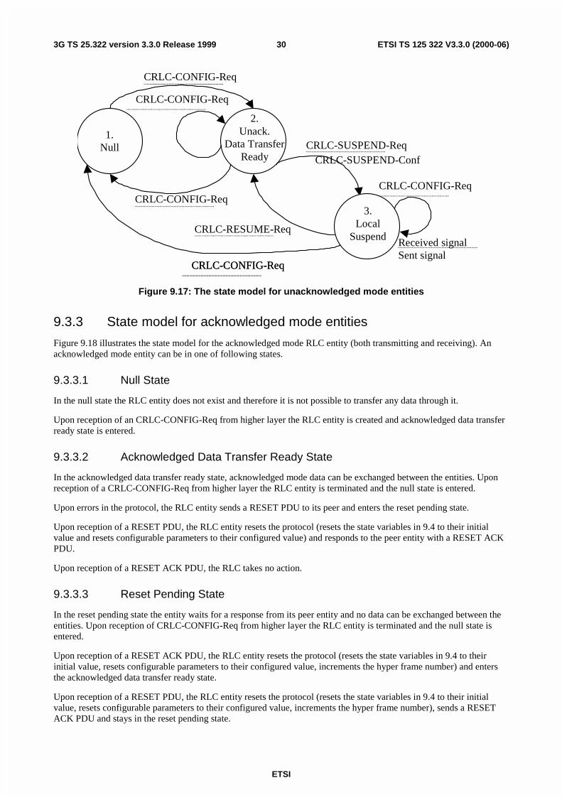
Figure 9.17 illustrates the state model for unacknowledged mode RLC entities (both transmitting and receiving). Anunacknowledged mode entity can be in one of following states.
9.3.2.1 Null State
In the null state the RLC entity does not exist and therefore it is not possible to transfer any data through it.
Upon reception of an CRLC-CONFIG-Req from higher layer the RLC entity is created and unacknowledged datatransfer ready state is entered.
9.3.2.2 Unacknowledged Data Transfer Ready State
In the unacknowledged data transfer ready, unacknowledged mode data can be exchanged between the entities. Uponreception of an CRLC-CONFIG-Req from higher layer the RLC entity is terminated and the null state is entered.
9.3.2.3 Local Suspend State
Upon reception of CRLC-SUSPEND-Req from higher layer (RRC) the RLC entity is suspended and the Local Suspendstate is entered. In the Local Suspend state RLC shall not send RLC-PDUs with SN>=VT(US)+N. Upon reception ofCRLC-RESUME-Req from higher layer (RRC) the RLC entity is resumed and the Data Transfer Ready state is entered.
ETSI
ETSI TS 125 322 V3.3.0 (2000-06)303G TS 25.322 version 3.3.0 Release 1999
2.Unack.
Data TransferReady
1.Null
CRLC-CONFIG-Req
CRLC-CONFIG-Req
CRLC-CONFIG-Req
Received signalSent signal
CRLC-SUSPEND-Req
CRLC-RESUME-Req
CRLC-SUSPEND-Conf
CRLC-CONFIG-Req
CRLC-CONFIG-Req
CRLC-CONFIG-Req
3.Local
Suspend
Figure 9.17: The state model for unacknowledged mode entities
9.3.3 State model for acknowledged mode entities
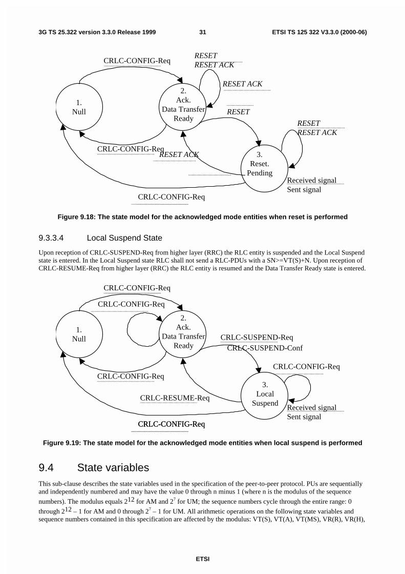
Figure 9.18 illustrates the state model for the acknowledged mode RLC entity (both transmitting and receiving). Anacknowledged mode entity can be in one of following states.
9.3.3.1 Null State
In the null state the RLC entity does not exist and therefore it is not possible to transfer any data through it.
Upon reception of an CRLC-CONFIG-Req from higher layer the RLC entity is created and acknowledged data transferready state is entered.
9.3.3.2 Acknowledged Data Transfer Ready State
In the acknowledged data transfer ready state, acknowledged mode data can be exchanged between the entities. Uponreception of a CRLC-CONFIG-Req from higher layer the RLC entity is terminated and the null state is entered.
Upon errors in the protocol, the RLC entity sends a RESET PDU to its peer and enters the reset pending state.
Upon reception of a RESET PDU, the RLC entity resets the protocol (resets the state variables in 9.4 to their initialvalue and resets configurable parameters to their configured value) and responds to the peer entity with a RESET ACKPDU.
Upon reception of a RESET ACK PDU, the RLC takes no action.
9.3.3.3 Reset Pending State
In the reset pending state the entity waits for a response from its peer entity and no data can be exchanged between theentities. Upon reception of CRLC-CONFIG-Req from higher layer the RLC entity is terminated and the null state isentered.
Upon reception of a RESET ACK PDU, the RLC entity resets the protocol (resets the state variables in 9.4 to theirinitial value, resets configurable parameters to their configured value, increments the hyper frame number) and entersthe acknowledged data transfer ready state.
Upon reception of a RESET PDU, the RLC entity resets the protocol (resets the state variables in 9.4 to their initialvalue, resets configurable parameters to their configured value, increments the hyper frame number), sends a RESETACK PDU and stays in the reset pending state.
ETSI
ETSI TS 125 322 V3.3.0 (2000-06)313G TS 25.322 version 3.3.0 Release 1999
2.Ack.
Data TransferReady
1.Null
CRLC-CONFIG-Req
CRLC-CONFIG-Req3.
Reset.Pending
RESET
RESET ACK
RESETRESET ACK
CRLC-CONFIG-Req
Received signalSent signal
RESET ACK
RESETRESET ACK
Figure 9.18: The state model for the acknowledged mode entities when reset is performed
9.3.3.4 Local Suspend State
Upon reception of CRLC-SUSPEND-Req from higher layer (RRC) the RLC entity is suspended and the Local Suspendstate is entered. In the Local Suspend state RLC shall not send a RLC-PDUs with a SN>=VT(S)+N. Upon reception ofCRLC-RESUME-Req from higher layer (RRC) the RLC entity is resumed and the Data Transfer Ready state is entered.
2.Ack.
Data TransferReady
1.Null
CRLC-CONFIG-Req
CRLC-CONFIG-Req
CRLC-CONFIG-Req
Received signalSent signal
CRLC-SUSPEND-Req
CRLC-RESUME-Req
CRLC-SUSPEND-Conf
CRLC-CONFIG-Req
CRLC-CONFIG-Req
CRLC-CONFIG-Req
3.Local
Suspend
Figure 9.19: The state model for the acknowledged mode entities when local suspend is performed
9.4 State variablesThis sub-clause describes the state variables used in the specification of the peer-to-peer protocol. PUs are sequentiallyand independently numbered and may have the value 0 through n minus 1 (where n is the modulus of the sequence
numbers). The modulus equals 212 for AM and 27 for UM; the sequence numbers cycle through the entire range: 0
through 212 – 1 for AM and 0 through 27 – 1 for UM. All arithmetic operations on the following state variables andsequence numbers contained in this specification are affected by the modulus: VT(S), VT(A), VT(MS), VR(R), VR(H),
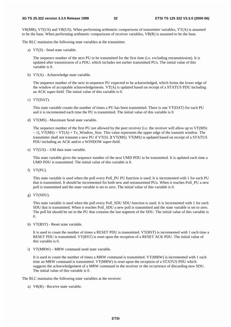
ETSI
ETSI TS 125 322 V3.3.0 (2000-06)323G TS 25.322 version 3.3.0 Release 1999
VR(MR), VT(US) and VR(US). When performing arithmetic comparisons of transmitter variables, VT(A) is assumedto be the base. When performing arithmetic comparisons of receiver variables, VR(R) is assumed to be the base.
The RLC maintains the following state variables at the transmitter.
a) VT(S) - Send state variable.
The sequence number of the next PU to be transmitted for the first time (i.e. excluding retransmission). It isupdated after transmission of a PDU, which includes not earlier transmitted PUs. The initial value of thisvariable is 0.
b) VT(A) - Acknowledge state variable.
The sequence number of the next in-sequence PU expected to be acknowledged, which forms the lower edge ofthe window of acceptable acknowledgements. VT(A) is updated based on receipt of a STATUS PDU includingan ACK super-field. The initial value of this variable is 0.
c) VT(DAT).
This state variable counts the number of times a PU has been transmitted. There is one VT(DAT) for each PUand it is incremented each time the PU is transmitted. The initial value of this variable is 0.
d) VT(MS) - Maximum Send state variable.
The sequence number of the first PU not allowed by the peer receiver [i.e. the receiver will allow up to VT(MS)– 1], VT(MS) = VT(A) + Tx_Window_Size. This value represents the upper edge of the transmit window. Thetransmitter shall not transmit a new PU if VT(S) ≥ VT(MS). VT(MS) is updated based on receipt of a STATUSPDU including an ACK and/or a WINDOW super-field.
e) VT(US) – UM data state variable.
This state variable gives the sequence number of the next UMD PDU to be transmitted. It is updated each time aUMD PDU is transmitted. The initial value of this variable is 0.
f) VT(PU).
This state variable is used when the poll every Poll_PU PU function is used. It is incremented with 1 for each PUthat is transmitted. It should be incremented for both new and retransmitted PUs. When it reaches Poll_PU a newpoll is transmitted and the state variable is set to zero. The initial value of this variable is 0.
g) VT(SDU).
This state variable is used when the poll every Poll_SDU SDU function is used. It is incremented with 1 for eachSDU that is transmitted. When it reaches Poll_SDU a new poll is transmitted and the state variable is set to zero.The poll bit should be set in the PU that contains the last segment of the SDU. The initial value of this variable is0.
h) VT(RST) - Reset state variable.
It is used to count the number of times a RESET PDU is transmitted. VT(RST) is incremented with 1 each time aRESET PDU is transmitted. VT(RST) is reset upon the reception of a RESET ACK PDU. The initial value ofthis variable is 0.
i) VT(MRW) – MRW command send state variable.
It is used to count the number of times a MRW command is transmitted. VT(MRW) is incremented with 1 eachtime an MRW command is transmitted. VT(MRW) is reset upon the reception of a STATUS PDU whichsuggests the acknowledgement of a MRW command in the receiver or the occurrence of discarding new SDU.The initial value of this variable is 0.
The RLC maintains the following state variables at the receiver:
a) VR(R) - Receive state variable.
ETSI
ETSI TS 125 322 V3.3.0 (2000-06)333G TS 25.322 version 3.3.0 Release 1999
The sequence number of the next in-sequence PU expected to be received. It is set equal to SNmax+1 uponreceipt of the next in-sequence PU, where SNmax is the sequence number of the highest received in-sequencePU. The initial value of this variable is 0.
b) VR(H) - Highest expected state variable.
The sequence number of the highest expected PU. This state variable is set equal to SN+1 onlywhen a new PU isreceived with VR(MR)>SN≥VR(H). The initial value of this variable is 0.
c) VR(MR) - Maximum acceptable Receive state variable.
The sequence number of the first PU not allowed by the receiver [i.e. the receiver will allow up to VR(MR) – 1],VR(MR) = VR(R) + Rx_Window_Size. The receiver shall discard PUs with SN ≥ VR(MR).
d) VR(US) - Receiver Send Sequence state variable.
The sequence number of the next PDU to be received. It shall set equal to SN + 1 upon reception of a PDU. Theinitial value of this variable is 0.
e) VR(EP) – Estimated PDU Counter state variable.
The number of PUs that should be received yet as a consequence of the transmission of the latest status report. Inacknowledged mode, this state variable is updated at the end of each transmission time interval. It isdecremented by the number of PUs that should have been received during the transmission time interval. IfVR(EP) is equal to zero, then check if all PUs requested for retransmission in the latest status report have beenreceived.
9.5 Timersa) Timer_Poll.
This timer is only used when the poll timer trigger is used. It is started when the transmitting side sends a poll tothe peer entity. The timer is stopped when receiving a STATUS PDU that contains an acknowledgement ornegative acknowledgement of the AMD PDU with SN=VT(S)-1 at the time the poll was transmitted. The valueof the timer is signalled by RRC.
If the timer expires and no STATUS PDU containing an acknowledgement or negative acknowledgement of theAMD PDU with SN=VT(S)-1 at the time the poll was transmitted has been received, the receiver is polled oncemore (either by the transmission of a PDU which was not yet sent, or by a retransmission) and the timer isrestarted with a new value of VT(S)-1. If there is no PU to be transmitted and all PUs have already beenacknowledged, the receiver shall not be polled.
If a new poll is sent when the timer is running it is restarted.
b) Timer_Poll_Prohibit.
This timer is only used when the poll prohibit function is used. It is used to prohibit transmission of polls withina certain period. A poll shall be delayed until the timer expires if a poll is triggered when the timer is active.Only one poll shall be transmitted when the timer expires even if several polls were triggered when the timer wasactive. If there is no PU to be transmitted and all PUs have already been acknowledged, a poll shall not betransmitted. This timer will not be stopped by a STATUS PDU. The value of the timer is signalled by RRC.
c) Timer_EPC.
This timer is only used when the EPC function is used and it accounts for the roundtrip delay, i.e. the time whenthe first retransmitted PU should be received after a status report has been sent. The timer is started when thefirst STATUS PDU of a status report is transmitted and when it expires EPC can start decrease (see subclause9.7.3). The value of the timer is signalled by RRC.
d) Timer_Discard.
This timer is used for the SDU discard function. In the transmitter, the timer is activated upon reception of aSDU from higher layer. One timer is used for each SDU that is received from higher layer. If the SDU has notbeen acknowledged and/or transmitted when the timer expires, the SDU is discarded. Following which, if the
ETSI
ETSI TS 125 322 V3.3.0 (2000-06)343G TS 25.322 version 3.3.0 Release 1999
SDU discard function uses explicit signalling, a Move Receiving Window request is sent to the receiver. Thevalue of the timer is signalled by RRC.
e) Timer_Poll_Periodic.
This timer is only used when the timer based polling is used. The timer is started when the RLC entity is created.Each time the timer expires a poll is transmitted (either by the transmission of a PDU which was not yet sent, orby a retransmission) and the timer is restarted. If there is no PU to be transmitted and all PUs have already beenacknowledged, a poll shall not be transmitted and the timer shall only be restarted. The value of the timer issignalled by RRC.
f) Timer_Status_Prohibit.
This timer is only used when the STATUS prohibit function is used. It prohibits the receiving side from sendingstatus reports containing any of the SUFIs LIST, BITMAP, RLIST or ACK. The timer is started when the lastSTATUS PDU in a status report is transmitted and no new status report containing the mentioned SUFIs can betransmitted before the timer has expired. The timer does not prohibit transmission of the SUFIs MRW,MRW_N_IFL, WINDOW or NO_MORE. The value of the timer is signalled by RRC.
g) Timer_Status_Periodic.
This timer is only used when timer based status report sending is used. The timer is started when the RLC entityis created. Each time the timer expires a status report is transmitted and the timer is restarted. The value of thetimer is signalled by RRC.
h) Timer_RST.
It is used to detect the loss of RESET ACK PDU from the peer RLC entity. This timer is set when the RESETPDU is transmitted. And it will be stopped upon reception of RESET ACK PDU. If it expires, RESET PDU willbe retransmitted. The value of the timer is signalled by RRC.
i) Timer_MRW.
This timer is used as part of the Move Receiving Window protocol. It is used to trigger the retransmission of astatus report containing an MRW SUFI field. The timer is started when the last STATUS PDU of the statusreport is first transmitted. Each time the timer expires the status report is retransmitted and the timer is restarted(when the last STATUS PDU of the status report is retransmitted). It shall be stopped when a STATUS PDU isreceived that indicates that VR(R) ≥ SN_MRW. It shall also be stopped if a new MRW procedure is triggeredwhile it is running. The value of the timer is signalled by RRC.
9.6 Protocol ParametersThe values of the protocol parameters in this section are signalled by RRC.
a) MaxDAT.
It is the maximum value for the number of retransmissions of a PU. This parameter is an upper limit of counterVT(DAT). When the value of VT(DAT) comes to MaxDAT, error recovery procedure will be performed.
b) Poll_PU.
This parameter indicates how often the transmitter should poll the receiver in case of polling every Poll_PU PU.This is an upper limit for the VT(PU) state variable, when VT(PU) reaches Poll_PU a poll is transmitted to thepeer entity.
c) Poll_SDU.
This parameter indicates how often the transmitter should poll the receiver in case of polling every Poll_SDUSDU. This is an upper limit for the VT(SDU) state variable, when VT(SDU) reaches Poll_SDU a poll istransmitted to the peer entity.
d) Poll_Window.
This parameter indicates when the transmitter should poll the receiver in case of performing window-basedpolling. A poll is transmitted when:
ETSI
ETSI TS 125 322 V3.3.0 (2000-06)353G TS 25.322 version 3.3.0 Release 1999
1 –(Tx_Window_Size + VT(MS) – VT(S))modTx_Window_Size
Tx_Window_Size* 100 > Poll_Window
e) MaxRST.
It is the maximum value for the number of retransmission of RESET PDU. This parameter is an upper limit ofcounter VT(RST). When the value of VT(RST) comes to MaxRST, the higher layer (RRC) is notified.
f) Tx_Window_Size.
The maximum allowed transmitter window size.
g) Rx_Window_Size.
The maximum allowed receiver window size.
h) MaxMRW.
It is the maximum value for the number of retransmissions of a MRW command. This parameter is an upperlimit of counter VT(MRW). When the value of VT(MRW) comes to MaxMRW, error recovery procedure willbe performed.
9.7 Specific functions
9.7.1 Polling function for acknowledged mode transfer
The transmitter of AMD PDUs may poll the receiver for a status report (consisting of one or several STATUS PDUs).The Polling bit in the AMD PDU indicates the poll request. There are several triggers for setting the polling bit. Thenetwork (RRC) controls, which triggers should be used for each RLC entity. Following triggers are possible:
1) Last PU in buffer.
The sender transmits a poll when the last PU available for transmission is transmitted.
2) Last PU in retransmission buffer.
The sender transmits a poll when the last PU to be retransmitted is transmitted.
3) Poll timer.
The timer Timer_Poll is started when a poll is transmitted to the receiver and if no STATUS PDU containing anacknowledgement or negative acknowledgement of the AMD PDU with SN=VT(S)-1 at the time the poll wastransmitted has been received before the timer Timer_Poll expires a new poll is transmitted to the receiver.
4) Every Poll_PU PU.
The sender polls the receiver every Poll_PU PU. Both retransmitted and new Pus shall be counted.
5) Every Poll_SDU SDU.
The sender polls the receiver every Poll_SDU SDU.
6) Poll_Window% of transmission window.
The sender polls the receiver when it has reached Poll_Window% of the transmission window.
7) Timer based.
The sender polls the receiver periodically.
Either the trigger "Last PU in buffer" and "Last PU in retransmission buffer" or "Timer based" can be chosen to avoiddeadlock for every RLC entity. The network also controls if the poll prohibit function shall be used. The poll bit shall be
ETSI
ETSI TS 125 322 V3.3.0 (2000-06)363G TS 25.322 version 3.3.0 Release 1999
set to 0 if the poll prohibit function is used and the timer Timer_Poll_Prohibit is active. This function has higher prioritythan any of the above mentioned triggers.
9.7.2 STATUS transmission for acknowledged mode
The receiver of AMD PDUs transmits status reports (each status report consists of one or several STATUS PDUs) tothe sender in order to inform about which PUs that have been received and not received. There are several triggers forsending a status report. The network (RRC) controls which triggers should be used for each RLC entity, except for one,which is always present. The receiver shall always send a status report when receiving a poll request. Except for thattrigger following triggers are configurable:
1) Detection of missing PU(s).
If the receiver detects one or several missing PUs it shall send a status report to the sender.
2) Timer based STATUS transfer.
The receiver transmits a status report periodically to the sender. The timer Timer_Status_Periodic controls thetime period.
3) The EPC mechanism.
The Timer EPC is started when the first STATUS PDU of a status report is transmitted to the peer entity. If notall PUs requested for retransmission have been received before the Timer EPC has expired a new status report istransmitted to the peer entity. A more detailed description of the EPC mechanism is given in subclause 9.7.4.
There are two functions that can prohibit the receiver from sending a status report. The network (RRC) controls whichfunctions should be used for each RLC entity. If any of the following functions is used the sending of the status reportshall be delayed, even if any of the conditions above are fulfilled:
1) STATUS prohibit.
The Timer_Status_Prohibit is started when the last STATUS PDU of a status report is transmitted to the peerentity. As long as the timer is running the receiving side is not allowed to send a status report to the peer entity.If a status report was triggered while the timer was running, the status report is transmitted after the timer hasexpired. The receiver shall only send one status report, even if there are several triggers when the timer running.This timer only prohibits the transmission of status reports containing any of the SUFIs LIST, BITMAP, RLISTor ACK. Status reports containing other SUFIs are not prohibited.
2) The EPC mechanism.
If the EPC mechanism is active and the sending of a status report is triggered it shall be delayed until the EPCmechanism has ended. The receiver shall only send one status report, even if there are several triggers when thetimer is active or the counter is counting down. This mechanism only prohibits the transmission of status reportscontaining any of the SUFIs LIST, BITMAP, RLIST or ACK. Status reports containing other SUFIs are notprohibited.
9.7.3 SDU discard function
The SDU discard function allows to discharge RLC PDU from the buffer on the transmitter side, when the transmissionof the RLC PDU does not success for a long time. The SDU discard function allows to avoid buffer overflow. Therewill be several alternative operation modes of the RLC SDU discard function, and which discard function to use will begiven by the QoS requirements of the Radio Access Bearer.
The following is a list of operation modes for the RLC SDU discard function.
ETSI
ETSI TS 125 322 V3.3.0 (2000-06)373G TS 25.322 version 3.3.0 Release 1999
Table 9.2: List of criteria's that control when to perform SDU discard
Operation mode PresenceTimer based discard, with explicit signalling Network controlledTimer based discard, without explicit signalling Network controlledSDU discard after MaxDAT number of retransmissions Network controlled
9.7.3.1 Timer based discard, with explicit signalling
This alternative uses a timer based triggering of SDU discard (Timer_Discard). This makes the SDU discard functioninsensitive to variations in the channel rate and provides means for exact definition of maximum delay. However, theSDU loss rate of the connection is increased as SDUs are discarded.
For every SDU received from a higher layer, timer monitoring of the transmission time of the SDU is started. If thetransmission time exceeds a predefined value for a SDU in acknowledged mode RLC, this SDU is discarded in thetransmitter and a Move Receiving Window (MRW) command is sent to the receiver so that AMD PDUs carrying thatSDU are discarded in the receiver and the receiver window is updated accordingly. Note that when the concatenationfunction is active, PDUs carrying segments of other SDUs that have not timed out shall not be discarded.
The MRW command is defined as a super-field in the RLC STATUS PDU (see subclause 9.2), and piggy backed tostatus information of transmissions in the opposite direction. If the MRW command has not been acknowledged byreceiver, it will be retransmitted. Therefore, SDU discard variants requiring peer-to-peer signalling are only possible forfull duplex connections.
9.7.3.2 Timer based discard, without explicit signalling
This alternative uses the same timer based trigger for SDU discard (Timer_Discard) as the one described in thesubclause 9.7.3.1. The difference is that this discard method does not use any peer-to-peer signalling. This function isapplied only for unacknowledged and transparent mode RLC and peer-to-peer signalling is never needed. The SDUs aresimply discarded in the transmitter, once the transmission time is exceeded.
9.7.3.3 SDU discard after MaxDAT number of retransmissions
This alternative uses the number of retransmissions as a trigger for SDU discard, and is therefore only applicable foracknowledged mode RLC. This makes the SDU discard function dependent of the channel rate. Also, this variant of theSDU discard function strives to keep the SDU loss rate constant for the connection, on the cost of a variable delay. SDUdiscard is triggered at the transmitter, and a MRW command is necessary to convey the discard information to thereceiver, like in the timer based discard with explicit signalling.
9.7.4 The Estimated PDU Counter
The Estimated PDU Counter is a mechanism used for scheduling the retransmission of status reports in the receiverside. With this mechanism, the receiver will send a new status report in which it requests for PUs not yet received. Thetime between two subsequent status report retransmissions is not fixed, but it is controlled by the Estimated PDUCounter (EPC), which adapt this time to the current bit rate, indicated in the TFI, in order to minimise the delay of thestatus report retransmission.
The EPC is a counter, which is decremented every transmission time interval with the estimated number of PUs thatshould have been transmitted during that transmission time interval. When the receiver detects that PDUs are missing itgenerates and sends a status report to the transmitter and sets the EPC equal to the number of requested PUs.
A special timer, called EPC timer, controls the maximum time that the EPC needs to wait before it will start countingdown. This timer starts immediately after a transmission of a retransmission request from the receiver (when the firstSTATUS PDU of the status report is transmitted). The EPC timer typically depends on the roundtrip delay, whichconsists of the propagation delay, processing time in the transmitter and receiver and the frame structure. This timer canalso be implemented as a counter, which counts the number of 10 ms radio frames that could be expected to elapsebefore the first requested AMD PDU is received.
When the EPC is equal to zero and not all of these requested PUs have been received correctly, a new status report willbe transmitted and the EPC will be reset accordingly. The EPC timer will be started once more.
ETSI
ETSI TS 125 322 V3.3.0 (2000-06)383G TS 25.322 version 3.3.0 Release 1999
9.7.5 Multiple payload units in an RLC PDU
The possibility to include multiple payload units (PU) into one RLC AMD PDU is part of the service capabilities of aUE in acknowledged mode. For Release 99, there shall be only one PU per AMD PDU.
A payload unit is the smallest unit that can be separately addressed for retransmission and is of fixed size, containingdata and optionally, length indicators and/or padding. The padding space of a PU can be used to piggyback STATUSPDUs.
The size of the PU is set by the RRC.
9.7.6 Local Suspend function for acknowledged mode transfer
The higher layer (RRC) may suspend the RLC entity. The CRLC-SUSPEND-Req indicates this request. The RLCentity shall, when receiving this request, not send RLC PDUs with SN>=VT(S)+N (N is given by theCRLC_SUSPEND-Req primitive). The RLC entity shall acknowledge the CRLC-SUSPEND-Req ordering a suspendwith a CRLC-SUSPEND-Conf with the current value of VT(S). The suspend state is left when a CRLC-RESUME-Reqprimitive indicating resume is received.
10 Handling of unknown, unforeseen and erroneousprotocol data
The list of error cases is reported below:
a) Inconsistent state variables.
If the RLC entity receives a PDU including "erroneous Sequence Number", state variables between peer entities may beinconsistent. Following shows "erroneous Sequence Number" examples:
- Each Sequence Number of missing PU informed by SUFI LIST is not within the value between "Acknowledgestate variable(VT(A))" and "Send state variable(VT(S))", and
- Each Sequence Number of missing PU informed by SUFI BITMAP is not within the value between"Acknowledge state variable(VT(A))-7" and "Send state variable(VT(S))", and
- LSN of SUFI ACK is not within the value between "Acknowledge state variable(VT(A))" and "Send statevariable(VT(S))".
In case of error situations the following actions are foreseen:
1) RLC entity should use RESET procedure in case of an unrecoverable error.
2) RLC entity should discard invalid PDU.
3) RLC entity should notify upper layer of unrecoverable error occurrence in case of failed retransmission.
11 Elementary procedures
11.1 Transparent mode data transfer procedure
11.1.1 Purpose
The transparent mode data transfer procedure is used for transferring of data between two RLC peer entities, which areoperating in transparent mode. Figure 11.1 below illustrates the elementary procedure for transparent mode datatransfer. The sender can be either the UE or the network and the receiver is either the network or the UE.
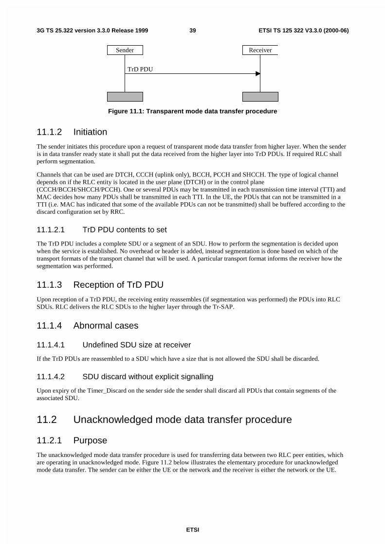
ETSI
ETSI TS 125 322 V3.3.0 (2000-06)393G TS 25.322 version 3.3.0 Release 1999
TrD PDU
Sender Receiver
Figure 11.1: Transparent mode data transfer procedure
11.1.2 Initiation
The sender initiates this procedure upon a request of transparent mode data transfer from higher layer. When the senderis in data transfer ready state it shall put the data received from the higher layer into TrD PDUs. If required RLC shallperform segmentation.
Channels that can be used are DTCH, CCCH (uplink only), BCCH, PCCH and SHCCH. The type of logical channeldepends on if the RLC entity is located in the user plane (DTCH) or in the control plane(CCCH/BCCH/SHCCH/PCCH). One or several PDUs may be transmitted in each transmission time interval (TTI) andMAC decides how many PDUs shall be transmitted in each TTI. In the UE, the PDUs that can not be transmitted in aTTI (i.e. MAC has indicated that some of the available PDUs can not be transmitted) shall be buffered according to thediscard configuration set by RRC.
11.1.2.1 TrD PDU contents to set
The TrD PDU includes a complete SDU or a segment of an SDU. How to perform the segmentation is decided uponwhen the service is established. No overhead or header is added, instead segmentation is done based on which of thetransport formats of the transport channel that will be used. A particular transport format informs the receiver how thesegmentation was performed.
11.1.3 Reception of TrD PDU
Upon reception of a TrD PDU, the receiving entity reassembles (if segmentation was performed) the PDUs into RLCSDUs. RLC delivers the RLC SDUs to the higher layer through the Tr-SAP.
11.1.4 Abnormal cases
11.1.4.1 Undefined SDU size at receiver
If the TrD PDUs are reassembled to a SDU which have a size that is not allowed the SDU shall be discarded.
11.1.4.2 SDU discard without explicit signalling
Upon expiry of the Timer_Discard on the sender side the sender shall discard all PDUs that contain segments of theassociated SDU.
11.2 Unacknowledged mode data transfer procedure
11.2.1 Purpose
The unacknowledged mode data transfer procedure is used for transferring data between two RLC peer entities, whichare operating in unacknowledged mode. Figure 11.2 below illustrates the elementary procedure for unacknowledgedmode data transfer. The sender can be either the UE or the network and the receiver is either the network or the UE.
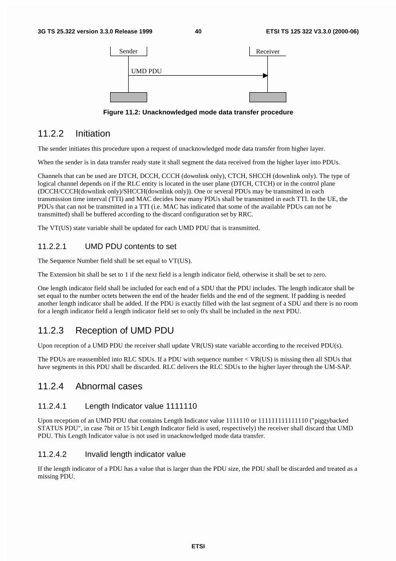
ETSI
ETSI TS 125 322 V3.3.0 (2000-06)403G TS 25.322 version 3.3.0 Release 1999
UMD PDU
Sender Receiver
Figure 11.2: Unacknowledged mode data transfer procedure
11.2.2 Initiation
The sender initiates this procedure upon a request of unacknowledged mode data transfer from higher layer.
When the sender is in data transfer ready state it shall segment the data received from the higher layer into PDUs.
Channels that can be used are DTCH, DCCH, CCCH (downlink only), CTCH, SHCCH (downlink only). The type oflogical channel depends on if the RLC entity is located in the user plane (DTCH, CTCH) or in the control plane(DCCH/CCCH(downlink only)/SHCCH(downlink only)). One or several PDUs may be transmitted in eachtransmission time interval (TTI) and MAC decides how many PDUs shall be transmitted in each TTI. In the UE, thePDUs that can not be transmitted in a TTI (i.e. MAC has indicated that some of the available PDUs can not betransmitted) shall be buffered according to the discard configuration set by RRC.
The VT(US) state variable shall be updated for each UMD PDU that is transmitted.
11.2.2.1 UMD PDU contents to set
The Sequence Number field shall be set equal to VT(US).
The Extension bit shall be set to 1 if the next field is a length indicator field, otherwise it shall be set to zero.
One length indicator field shall be included for each end of a SDU that the PDU includes. The length indicator shall beset equal to the number octets between the end of the header fields and the end of the segment. If padding is neededanother length indicator shall be added. If the PDU is exactly filled with the last segment of a SDU and there is no roomfor a length indicator field a length indicator field set to only 0's shall be included in the next PDU.
11.2.3 Reception of UMD PDU
Upon reception of a UMD PDU the receiver shall update VR(US) state variable according to the received PDU(s).
The PDUs are reassembled into RLC SDUs. If a PDU with sequence number < VR(US) is missing then all SDUs thathave segments in this PDU shall be discarded. RLC delivers the RLC SDUs to the higher layer through the UM-SAP.
11.2.4 Abnormal cases
11.2.4.1 Length Indicator value 1111110
Upon reception of an UMD PDU that contains Length Indicator value 1111110 or 111111111111110 ("piggybackedSTATUS PDU", in case 7bit or 15 bit Length Indicator field is used, respectively) the receiver shall discard that UMDPDU. This Length Indicator value is not used in unacknowledged mode data transfer.
11.2.4.2 Invalid length indicator value
If the length indicator of a PDU has a value that is larger than the PDU size, the PDU shall be discarded and treated as amissing PDU.
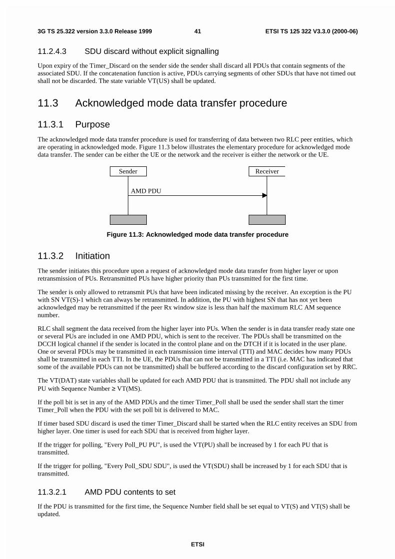
ETSI
ETSI TS 125 322 V3.3.0 (2000-06)413G TS 25.322 version 3.3.0 Release 1999
11.2.4.3 SDU discard without explicit signalling
Upon expiry of the Timer_Discard on the sender side the sender shall discard all PDUs that contain segments of theassociated SDU. If the concatenation function is active, PDUs carrying segments of other SDUs that have not timed outshall not be discarded. The state variable VT(US) shall be updated.
11.3 Acknowledged mode data transfer procedure
11.3.1 Purpose
The acknowledged mode data transfer procedure is used for transferring of data between two RLC peer entities, whichare operating in acknowledged mode. Figure 11.3 below illustrates the elementary procedure for acknowledged modedata transfer. The sender can be either the UE or the network and the receiver is either the network or the UE.
AMD PDU
Sender Receiver
Figure 11.3: Acknowledged mode data transfer procedure
11.3.2 Initiation
The sender initiates this procedure upon a request of acknowledged mode data transfer from higher layer or uponretransmission of PUs. Retransmitted PUs have higher priority than PUs transmitted for the first time.
The sender is only allowed to retransmit PUs that have been indicated missing by the receiver. An exception is the PUwith SN VT(S)-1 which can always be retransmitted. In addition, the PU with highest SN that has not yet beenacknowledged may be retransmitted if the peer Rx window size is less than half the maximum RLC AM sequencenumber.
RLC shall segment the data received from the higher layer into PUs. When the sender is in data transfer ready state oneor several PUs are included in one AMD PDU, which is sent to the receiver. The PDUs shall be transmitted on theDCCH logical channel if the sender is located in the control plane and on the DTCH if it is located in the user plane.One or several PDUs may be transmitted in each transmission time interval (TTI) and MAC decides how many PDUsshall be transmitted in each TTI. In the UE, the PDUs that can not be transmitted in a TTI (i.e. MAC has indicated thatsome of the available PDUs can not be transmitted) shall be buffered according to the discard configuration set by RRC.
The VT(DAT) state variables shall be updated for each AMD PDU that is transmitted. The PDU shall not include anyPU with Sequence Number ≥ VT(MS).
If the poll bit is set in any of the AMD PDUs and the timer Timer_Poll shall be used the sender shall start the timerTimer_Poll when the PDU with the set poll bit is delivered to MAC.
If timer based SDU discard is used the timer Timer_Discard shall be started when the RLC entity receives an SDU fromhigher layer. One timer is used for each SDU that is received from higher layer.
If the trigger for polling, "Every Poll_PU PU", is used the VT(PU) shall be increased by 1 for each PU that istransmitted.
If the trigger for polling, "Every Poll_SDU SDU", is used the VT(SDU) shall be increased by 1 for each SDU that istransmitted.
11.3.2.1 AMD PDU contents to set
If the PDU is transmitted for the first time, the Sequence Number field shall be set equal to VT(S) and VT(S) shall beupdated.
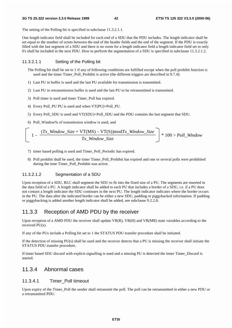
ETSI
ETSI TS 125 322 V3.3.0 (2000-06)423G TS 25.322 version 3.3.0 Release 1999
The setting of the Polling bit is specified in subclause 11.3.2.1.1.
One length indicator field shall be included for each end of a SDU that the PDU includes. The length indicator shall beset equal to the number of octets between the end of the header fields and the end of the segment. If the PDU is exactlyfilled with the last segment of a SDU and there is no room for a length indicator field a length indicator field set to only0's shall be included in the next PDU. How to perform the segmentation of a SDU is specified in subclause 11.3.2.1.2.
11.3.2.1.1 Setting of the Polling bit
The Polling bit shall be set to 1 if any of following conditions are fulfilled except when the poll prohibit function isused and the timer Timer_Poll_Prohibit is active (the different triggers are described in 9.7.4):
1) Last PU in buffer is used and the last PU available for transmission is transmitted.
2) Last PU in retransmission buffer is used and the last PU to be retransmitted is transmitted.
3) Poll timer is used and timer Timer_Poll has expired.
4) Every Poll_PU PU is used and when VT(PU)=Poll_PU.
5) Every Poll_SDU is used and VT(SDU)=Poll_SDU and the PDU contains the last segment that SDU.
6) Poll_Window% of transmission window is used, and
1 –(Tx_Window_Size + VT(MS) – VT(S))modTx_Window_Size
Tx_Window_Size* 100 > Poll_Window
7) timer based polling is used and Timer_Poll_Periodic has expired.
8) Poll prohibit shall be used, the timer Timer_Poll_Prohibit has expired and one or several polls were prohibitedduring the time Timer_Poll_Prohibit was active.
11.3.2.1.2 Segmentation of a SDU
Upon reception of a SDU, RLC shall segment the SDU to fit into the fixed size of a PU. The segments are inserted inthe data field of a PU. A length indicator shall be added to each PU that includes a border of a SDU, i.e. if a PU doesnot contain a length indicator the SDU continues in the next PU. The length indicator indicates where the border occursin the PU. The data after the indicated border can be either a new SDU, padding or piggybacked information. If paddingor piggybacking is added another length indicator shall be added, see subclause 9.2.2.8.
11.3.3 Reception of AMD PDU by the receiver
Upon reception of a AMD PDU the receiver shall update VR(R), VR(H) and VR(MR) state variables according to thereceived PU(s).
If any of the PUs include a Polling bit set to 1 the STATUS PDU transfer procedure shall be initiated.
If the detection of missing PU(s) shall be used and the receiver detects that a PU is missing the receiver shall initiate theSTATUS PDU transfer procedure.
If timer based SDU discard with explicit signalling is used and a missing PU is detected the timer Timer_Discard isstarted.
11.3.4 Abnormal cases
11.3.4.1 Timer_Poll timeout
Upon expiry of the Timer_Poll the sender shall retransmit the poll. The poll can be retransmitted in either a new PDU ora retransmitted PDU.
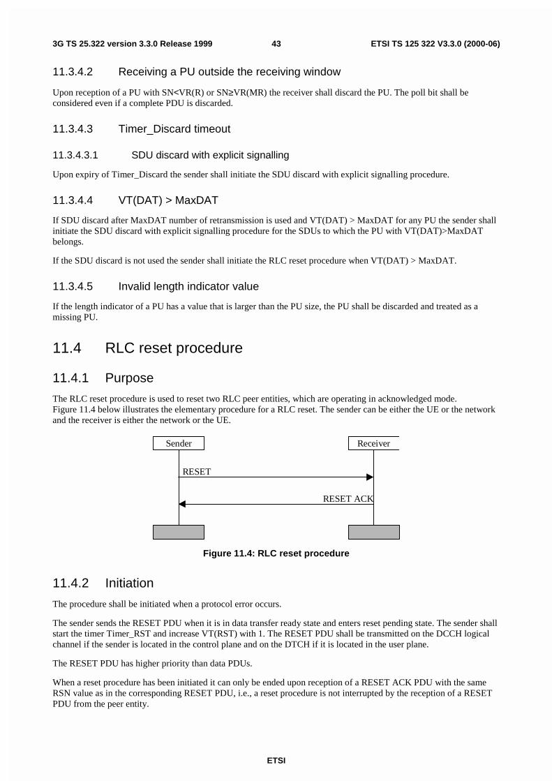
ETSI
ETSI TS 125 322 V3.3.0 (2000-06)433G TS 25.322 version 3.3.0 Release 1999
11.3.4.2 Receiving a PU outside the receiving window
Upon reception of a PU with SN<VR(R) or SN≥VR(MR) the receiver shall discard the PU. The poll bit shall beconsidered even if a complete PDU is discarded.
11.3.4.3 Timer_Discard timeout
11.3.4.3.1 SDU discard with explicit signalling
Upon expiry of Timer_Discard the sender shall initiate the SDU discard with explicit signalling procedure.
11.3.4.4 VT(DAT) > MaxDAT
If SDU discard after MaxDAT number of retransmission is used and VT(DAT) > MaxDAT for any PU the sender shallinitiate the SDU discard with explicit signalling procedure for the SDUs to which the PU with VT(DAT)>MaxDATbelongs.
If the SDU discard is not used the sender shall initiate the RLC reset procedure when VT(DAT) > MaxDAT.
11.3.4.5 Invalid length indicator value
If the length indicator of a PU has a value that is larger than the PU size, the PU shall be discarded and treated as amissing PU.
11.4 RLC reset procedure
11.4.1 Purpose
The RLC reset procedure is used to reset two RLC peer entities, which are operating in acknowledged mode.Figure 11.4 below illustrates the elementary procedure for a RLC reset. The sender can be either the UE or the networkand the receiver is either the network or the UE.
RESET ACK
RESET
Sender Receiver
Figure 11.4: RLC reset procedure
11.4.2 Initiation
The procedure shall be initiated when a protocol error occurs.
The sender sends the RESET PDU when it is in data transfer ready state and enters reset pending state. The sender shallstart the timer Timer_RST and increase VT(RST) with 1. The RESET PDU shall be transmitted on the DCCH logicalchannel if the sender is located in the control plane and on the DTCH if it is located in the user plane.
The RESET PDU has higher priority than data PDUs.
When a reset procedure has been initiated it can only be ended upon reception of a RESET ACK PDU with the sameRSN value as in the corresponding RESET PDU, i.e., a reset procedure is not interrupted by the reception of a RESETPDU from the peer entity.
ETSI
ETSI TS 125 322 V3.3.0 (2000-06)443G TS 25.322 version 3.3.0 Release 1999
11.4.2.1 RESET PDU contents to set
The size of the RESET PDU shall be equal to one of the allowed PDU sizes. The RSN field shall indicate the sequencenumber of the RESET PDU. This sequence number is incremented every time a new RESET PDU is transmitted.
11.4.3 Reception of the RESET PDU by the receiver
Upon reception of a RESET PDU the receiver shall respond with a RESET ACK PDU. The receiver resets the statevariables in 9.4 to their initial value and resets configurable parameters to their configured value.
In the received RESET PDU the Receiver shall check the value of RSN (Reset Sequence Number) field. If the value ofthe RSN field is different from the RSN value in the previously received RESET PDU the Receiver shall increase thevalue of the HFN by one.
If the value of the RSN is equal to the RSN value in the previously received RESET PDU, (i.e. the RESET PDU is aretransmitted RESET PDU) the value of the HFN shall not be increased and only a RESET ACK PDU shall be sent tothe peer RLC entity.
The RESET ACK PDU shall be transmitted on the DCCH logical channel if the sender is located in the control planeand on the DTCH if it is located in the user plane.
The RESET ACK PDU has higher priority than data PDUs.
11.4.3.1 RESET ACK PDU contents to set
The size of the RESET ACK PDU shall be equal to one of the allowed PDU sizes. The RSN field shall always be set tothe same value as in the corresponding RESET PDU.
11.4.4 Reception of the RESET ACK PDU by the sender
When the sender is in reset pending state and receives a RESET ACK PDU with the same RSN value as in thecorresponding RESET PDU the Timer_RST shall be stopped and the value of the HFN shall be increased by one. Thesender resets the state variables in 9.4 to their initial value and resets configurable parameters to their configured value.The sender shall enter data transfer ready state.
Upon reception of a RESET ACK PDU with a different RSN value as in the corresponding RESET PDU the RESETACK PDU is discarded.
Upon reception of a RESET ACK PDU in data transfer ready state the RESET ACK PDU is discarded.
11.4.5 Abnormal cases
11.4.5.1 Timer_RST timeout
Upon expiry of Timer_RST the sender shall retransmit the RESET PDU and increase VT(RST) with 1. In theretransmitted RESET PDU the RSN field value shall not be incremented.
11.4.5.2 VT(RST) ≥ MaxRST
If VT(RST) becomes larger or equal to MaxRST the RRC layer shall be informed.
11.4.5.3 Reception of the RESET PDU by the sender
Upon reception of a RESET PDU in reset pending state the sender resets the state variables in 9.4 to their initial value,resets configurable parameters to their configured value and increments the hyper frame number. The sender shall stayin the reset pending state. The sender shall retransmit the RESET PDU and increase VT(RST) with 1. The sender canenter data transfer ready state only upon reception of a RESET ACK PDU with the same RSN value as in thecorresponding RESET PDU.
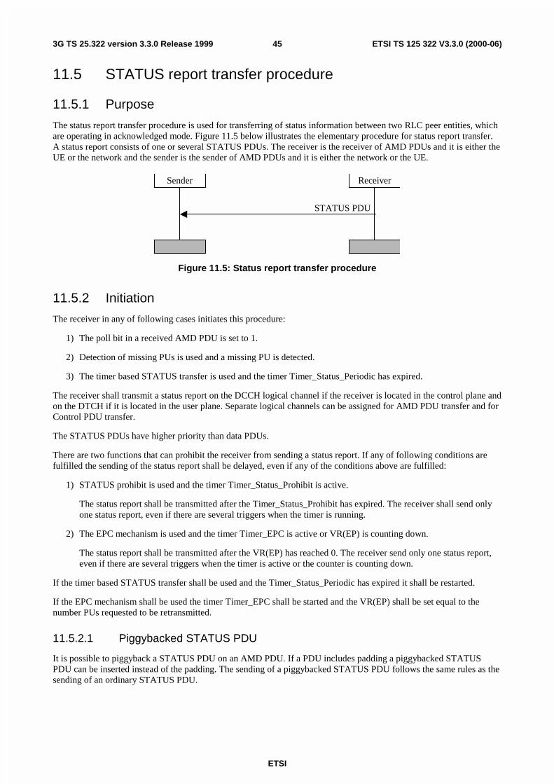
ETSI
ETSI TS 125 322 V3.3.0 (2000-06)453G TS 25.322 version 3.3.0 Release 1999
11.5 STATUS report transfer procedure
11.5.1 Purpose
The status report transfer procedure is used for transferring of status information between two RLC peer entities, whichare operating in acknowledged mode. Figure 11.5 below illustrates the elementary procedure for status report transfer.A status report consists of one or several STATUS PDUs. The receiver is the receiver of AMD PDUs and it is either theUE or the network and the sender is the sender of AMD PDUs and it is either the network or the UE.
Sender Receiver
STATUS PDU
Figure 11.5: Status report transfer procedure
11.5.2 Initiation
The receiver in any of following cases initiates this procedure:
1) The poll bit in a received AMD PDU is set to 1.
2) Detection of missing PUs is used and a missing PU is detected.
3) The timer based STATUS transfer is used and the timer Timer_Status_Periodic has expired.
The receiver shall transmit a status report on the DCCH logical channel if the receiver is located in the control plane andon the DTCH if it is located in the user plane. Separate logical channels can be assigned for AMD PDU transfer and forControl PDU transfer.
The STATUS PDUs have higher priority than data PDUs.
There are two functions that can prohibit the receiver from sending a status report. If any of following conditions arefulfilled the sending of the status report shall be delayed, even if any of the conditions above are fulfilled:
1) STATUS prohibit is used and the timer Timer_Status_Prohibit is active.
The status report shall be transmitted after the Timer_Status_Prohibit has expired. The receiver shall send onlyone status report, even if there are several triggers when the timer is running.
2) The EPC mechanism is used and the timer Timer_EPC is active or VR(EP) is counting down.
The status report shall be transmitted after the VR(EP) has reached 0. The receiver send only one status report,even if there are several triggers when the timer is active or the counter is counting down.
If the timer based STATUS transfer shall be used and the Timer_Status_Periodic has expired it shall be restarted.
If the EPC mechanism shall be used the timer Timer_EPC shall be started and the VR(EP) shall be set equal to thenumber PUs requested to be retransmitted.
11.5.2.1 Piggybacked STATUS PDU
It is possible to piggyback a STATUS PDU on an AMD PDU. If a PDU includes padding a piggybacked STATUSPDU can be inserted instead of the padding. The sending of a piggybacked STATUS PDU follows the same rules as thesending of an ordinary STATUS PDU.
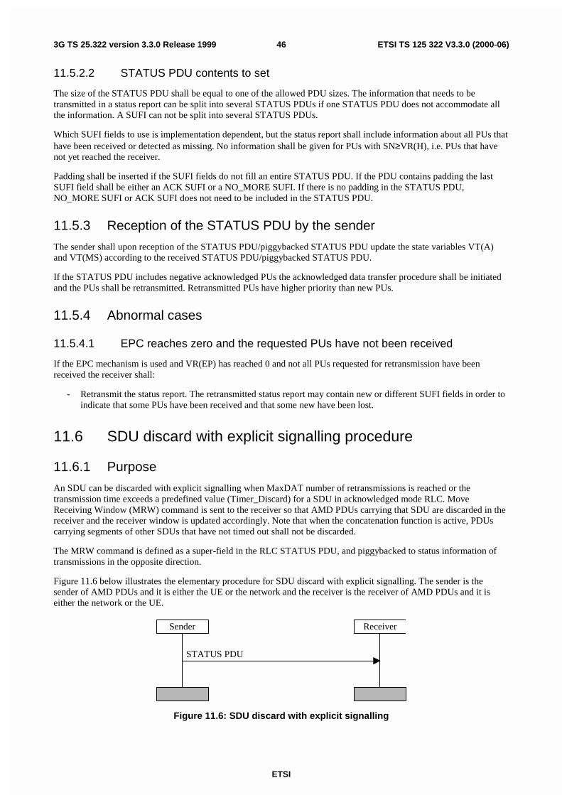
ETSI
ETSI TS 125 322 V3.3.0 (2000-06)463G TS 25.322 version 3.3.0 Release 1999
11.5.2.2 STATUS PDU contents to set
The size of the STATUS PDU shall be equal to one of the allowed PDU sizes. The information that needs to betransmitted in a status report can be split into several STATUS PDUs if one STATUS PDU does not accommodate allthe information. A SUFI can not be split into several STATUS PDUs.
Which SUFI fields to use is implementation dependent, but the status report shall include information about all PUs thathave been received or detected as missing. No information shall be given for PUs with SN≥VR(H), i.e. PUs that havenot yet reached the receiver.
Padding shall be inserted if the SUFI fields do not fill an entire STATUS PDU. If the PDU contains padding the lastSUFI field shall be either an ACK SUFI or a NO_MORE SUFI. If there is no padding in the STATUS PDU,NO_MORE SUFI or ACK SUFI does not need to be included in the STATUS PDU.
11.5.3 Reception of the STATUS PDU by the sender
The sender shall upon reception of the STATUS PDU/piggybacked STATUS PDU update the state variables VT(A)and VT(MS) according to the received STATUS PDU/piggybacked STATUS PDU.
If the STATUS PDU includes negative acknowledged PUs the acknowledged data transfer procedure shall be initiatedand the PUs shall be retransmitted. Retransmitted PUs have higher priority than new PUs.
11.5.4 Abnormal cases
11.5.4.1 EPC reaches zero and the requested PUs have not been received
If the EPC mechanism is used and VR(EP) has reached 0 and not all PUs requested for retransmission have beenreceived the receiver shall:
- Retransmit the status report. The retransmitted status report may contain new or different SUFI fields in order toindicate that some PUs have been received and that some new have been lost.
11.6 SDU discard with explicit signalling procedure
11.6.1 Purpose
An SDU can be discarded with explicit signalling when MaxDAT number of retransmissions is reached or thetransmission time exceeds a predefined value (Timer_Discard) for a SDU in acknowledged mode RLC. MoveReceiving Window (MRW) command is sent to the receiver so that AMD PDUs carrying that SDU are discarded in thereceiver and the receiver window is updated accordingly. Note that when the concatenation function is active, PDUscarrying segments of other SDUs that have not timed out shall not be discarded.
The MRW command is defined as a super-field in the RLC STATUS PDU, and piggybacked to status information oftransmissions in the opposite direction.
Figure 11.6 below illustrates the elementary procedure for SDU discard with explicit signalling. The sender is thesender of AMD PDUs and it is either the UE or the network and the receiver is the receiver of AMD PDUs and it iseither the network or the UE.
STATUS PDU
Sender Receiver
Figure 11.6: SDU discard with explicit signalling
ETSI
ETSI TS 125 322 V3.3.0 (2000-06)473G TS 25.322 version 3.3.0 Release 1999
11.6.2 Initiation
This procedure is initiated by the sender when the following conditions are fulfilled:
1) SDU discard with explicit signalling is used.
2) MaxDAT number of retransmissions is reached or Timer_Discard expires for a SDU in acknowledged modeRLC.
The sender shall discard all PUs that contain a segment of the associated SDU. If the concatenation function is active,PDUs carrying segments of other SDUs that have not timed out shall not be discarded.
The sender shall transmit a status report on the DCCH logical channel if the sender is located in the control plane andon the DTCH if it is located in the user plane.
If the PU with sequence number SN_MRWLENGTH contains LI indicating trailing data from the discarded SDU, thetransmitter shall send SUFI MRW_N_IFL indicating to the receiver to discard the first N LIs and the correspondingdata bytes. Otherwise the transmitter shall send SUFI MRW.
This status report is sent even if the 'STATUS prohibit' is used and the timer 'Timer_Status_Prohibit' is active.
The STATUS PDUs have higher priority than data PDUs.
The sender shall start timer Timer_MRW. If a new SDU discard procedure is triggered when Timer_MRW is running,no new MRW SUFIs should be sent before the STATUS PDU is received indicating the appropriate value of VR(R).
11.6.2.1 Piggybacked STATUS PDU
It is possible to piggyback a STATUS PDU on an AMD PDU. If a PDU includes padding a piggybacked STATUSPDU can be inserted instead of the padding.
11.6.2.2 STATUS PDU contents to set
The size of the STATUS PDU shall be equal to one of the allowed PDU sizes. The information that needs to betransmitted in a status report can be split into several STATUS PDUs if one STATUS PDU does not accommodate allthe information.
The status report shall include the MRW/MRW_N_IFL SUFI, other SUFI fields can be used additionally.MRW/MRW_N_IFL SUFI shall convey information about the discarded SDU(s) to the receiver.
Padding shall be inserted if the SUFI fields do not fill the entire STATUS PDU. If the PDU contains padding the lastSUFI field shall be a No More Data super-field.
11.6.3 Reception of the STATUS PDU by the receiver
The receiver shall upon reception of the STATUS PDU/piggybacked STATUS PDU discard PUs and update the statevariables VR(R), VR(H) and VR(MR) according to the received STATUS PDU/piggybacked STATUS PDU.Additionally the receiver should indicate the higher layers of all of the discarded SDUs.
The receiver shall initiate the transmission of a status report indicating the revised value of VR(R).
In case of receiving SUFI_MRW, the receiver shall start reassembling the next SDU from the first data byte of the PUwith sequence number SN_MRWLENGTH.
If the receiver receives SUFI MRW_N_IFL , it shall discard the first N LIs and the corresponding data bytes and startreassembling the next SDU from the data byte indicated by the N+1:th LI field of the PU with sequence numberSN_MRWLENGTH.
11.6.4 Reception of STATUS PDU if VR(R) ≥ SN_MRWLENGTH
The procedure is terminated in the sender when a STATUS PDU is received indicating a value of VR(R) ≥SN_MRWLENGTH. If this occurs Timer_MRW is stopped thereby terminating the procedure.
ETSI
ETSI TS 125 322 V3.3.0 (2000-06)483G TS 25.322 version 3.3.0 Release 1999
If new SDUs are discarded during the running of the Timer_MRW, a new discard procedure should be initiated noearlier than after the reception of STATUS PDU with VR(R) ≥ SN_MRWLENGTH.
11.6.5 Expiration of timer Timer_MRW
If Timer_MRW expires before a STATUS PDU is received indicating a value of VR(R) greater or equal to the MRWparameter then the STATUS(MRW) shall be retransmitted, VT(MRW) is incremented by one and Timer_MRWrestarted. MRW SUFI should be exactly the same as previously transmitted even though some new SDUs would havebeen discarded during the running of the Timer_MRW.
11.6.6 Abnormal cases
11.6.6.1 Obsolete/corrupted MRW command
If the MRW command contains outdated information about the receiver window (receiver window already movedfurther than MRW command is indicating), the MRW command shall be discarded and a status report containing SUFIACK shall be transmitted.
11.6.6.2 VT(MRW) equals MaxMRW
If the number of retransmission of a MRW command (i.e. VT(MRW)) reaches MaxMRW, an error indication shall bepassed to RRC and RESET procedure should be performed.
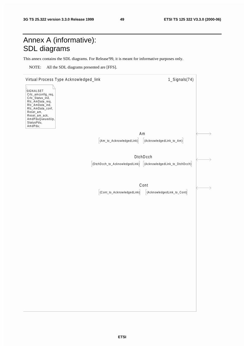
ETSI
ETSI TS 125 322 V3.3.0 (2000-06)493G TS 25.322 version 3.3.0 Release 1999
Annex A (informative):SDL diagramsThis annex contains the SDL diagrams. For Release'99, it is meant for informative purposes only.
NOTE: All the SDL diagrams presented are [FFS].
;S IG N A LS ET C rlc_am config_ req, C rlc_S ta tus_ind, R lc_ A mData_req, R lc_ A mData_ ind, R lc_ A mData_conf, R eset_am, R eset_am_ack, A m dP duQ ueu edUp, S tatusPdu, A m dP du ;
V irtua l P roce ss T ype A ckn ow le dge d_ link 1_ S igna ls(7 4)
A m
(A ckn owledge dLink_ to_Am)(A m_ to_A ckno wledged Link)
D tchD cch
(D tchD cch_ to_A cknowledgedLink) (A ckn owledge dLink_ to_DtchDcch)
C on t
(A ckn owledge dLink_ to_Cont)(C ont_to_A cknow ledgedL ink)
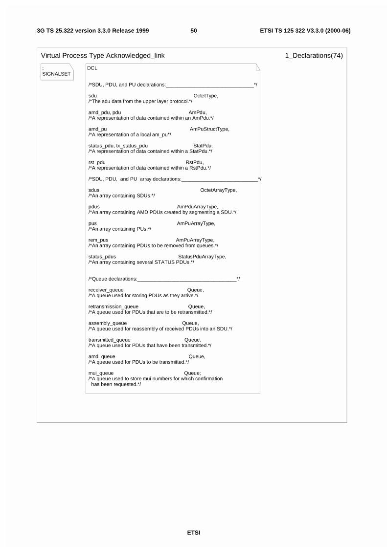
ETSI
ETSI TS 125 322 V3.3.0 (2000-06)503G TS 25.322 version 3.3.0 Release 1999
;SIGNALSET
Virtual Process Type Acknowledged_link 1_Declarations(74)
DCL
/*SDU, PDU, and PU declarations:_______________________________*/
sdu OctetType, /*The sdu data from the upper layer protocol.*/ amd_pdu, pdu AmPdu, /*A representation of data contained within an AmPdu.*/
amd_pu AmPuStructType, /*A representation of a local am_pu*/
status_pdu, tx_status_pdu StatPdu, /*A representation of data contained within a StatPdu.*/
rst_pdu RstPdu, /*A representation of data contained within a RstPdu.*/ /*SDU, PDU, and PU array declarations:___________________________*/
sdus OctetArrayType, /*An array containing SDUs.*/
pdus AmPduArrayType, /*An array containing AMD PDUs created by segmenting a SDU.*/
pus AmPuArrayType, /*An array containing PUs.*/ rem_pus AmPuArrayType, /*An array containing PDUs to be removed from queues.*/
status_pdus StatusPduArrayType, /*An array containing several STATUS PDUs.*/
/*Queue declarations:___________________________________*/
receiver_queue Queue, /*A queue used for storing PDUs as they arrive.*/
retransmission_queue Queue, /*A queue used for PDUs that are to be retransmitted.*/
assembly_queue Queue, /*A queue used for reassembly of received PDUs into an SDU.*/
transmitted_queue Queue, /*A queue used for PDUs that have been transmitted.*/
amd_queue Queue, /*A queue used for PDUs to be transmitted.*/
mui_queue Queue; /*A queue used to store mui numbers for which confirmation has been requested.*/
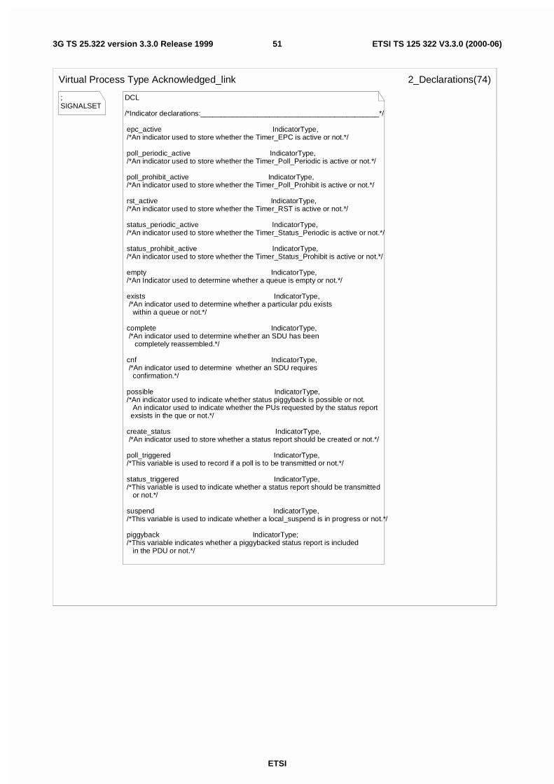
ETSI
ETSI TS 125 322 V3.3.0 (2000-06)513G TS 25.322 version 3.3.0 Release 1999
;SIGNALSET
Virtual Process Type Acknowledged_link 2_Declarations(74)
DCL
/*Indicator declarations:____________________________________________*/
epc_active IndicatorType, /*An indicator used to store whether the Timer_EPC is active or not.*/
poll_periodic_active IndicatorType, /*An indicator used to store whether the Timer_Poll_Periodic is active or not.*/
poll_prohibit_active IndicatorType, /*An indicator used to store whether the Timer_Poll_Prohibit is active or not.*/
rst_active IndicatorType, /*An indicator used to store whether the Timer_RST is active or not.*/
status_periodic_active IndicatorType, /*An indicator used to store whether the Timer_Status_Periodic is active or not.*/
status_prohibit_active IndicatorType, /*An indicator used to store whether the Timer_Status_Prohibit is active or not.*/
empty IndicatorType, /*An Indicator used to determine whether a queue is empty or not.*/
exists IndicatorType, /*An indicator used to determine whether a particular pdu exists within a queue or not.*/
complete IndicatorType, /*An indicator used to determine whether an SDU has been completely reassembled.*/
cnf IndicatorType, /*An indicator used to determine whether an SDU requires confirmation.*/
possible IndicatorType, /*An indicator used to indicate whether status piggyback is possible or not. An indicator used to indicate whether the PUs requested by the status report exsists in the que or not.*/
create_status IndicatorType, /*An indicator used to store whether a status report should be created or not.*/
poll_triggered IndicatorType, /*This variable is used to record if a poll is to be transmitted or not.*/
status_triggered IndicatorType, /*This variable is used to indicate whether a status report should be transmitted or not.*/
suspend IndicatorType, /*This variable is used to indicate whether a local_suspend is in progress or not.*/
piggyback IndicatorType; /*This variable indicates whether a piggybacked status report is included in the PDU or not.*/
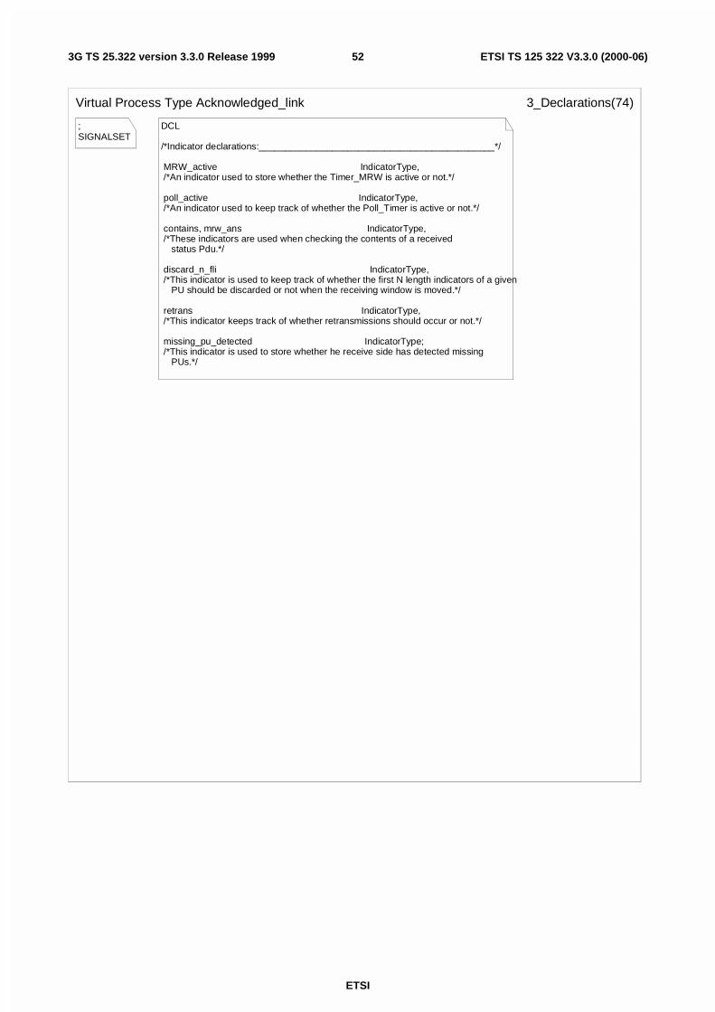
ETSI
ETSI TS 125 322 V3.3.0 (2000-06)523G TS 25.322 version 3.3.0 Release 1999
;SIGNALSET
Virtual Process Type Acknowledged_link 3_Declarations(74)
DCL
/*Indicator declarations:_____________________________________________*/
MRW_active IndicatorType, /*An indicator used to store whether the Timer_MRW is active or not.*/
poll_active IndicatorType, /*An indicator used to keep track of whether the Poll_Timer is active or not.*/
contains, mrw_ans IndicatorType, /*These indicators are used when checking the contents of a received status Pdu.*/
discard_n_fli IndicatorType, /*This indicator is used to keep track of whether the first N length indicators of a given PU should be discarded or not when the receiving window is moved.*/
retrans IndicatorType, /*This indicator keeps track of whether retransmissions should occur or not.*/
missing_pu_detected IndicatorType; /*This indicator is used to store whether he receive side has detected missing PUs.*/
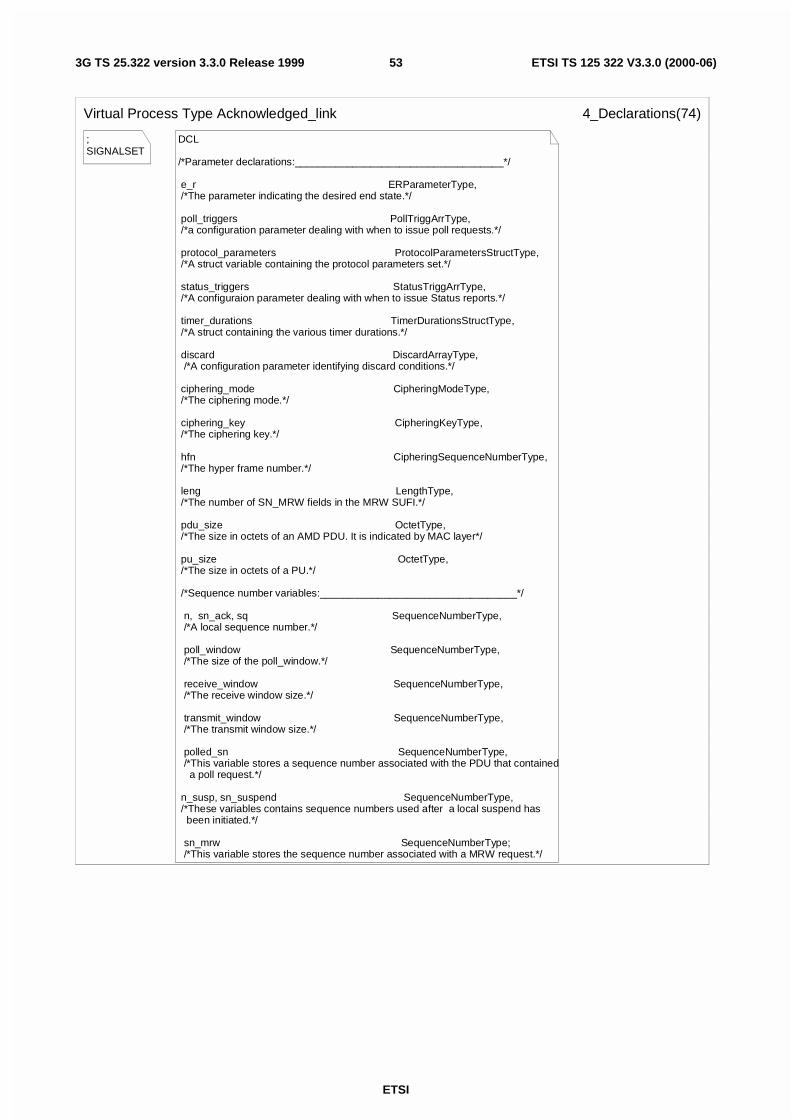
ETSI
ETSI TS 125 322 V3.3.0 (2000-06)533G TS 25.322 version 3.3.0 Release 1999
;SIGNALSET
Virtual Process Type Acknowledged_link 4_Declarations(74)
DCL
/*Parameter declarations:____________________________________*/
e_r ERParameterType, /*The parameter indicating the desired end state.*/
poll_triggers PollTriggArrType, /*a configuration parameter dealing with when to issue poll requests.*/
protocol_parameters ProtocolParametersStructType, /*A struct variable containing the protocol parameters set.*/
status_triggers StatusTriggArrType, /*A configuraion parameter dealing with when to issue Status reports.*/
timer_durations TimerDurationsStructType, /*A struct containing the various timer durations.*/
discard DiscardArrayType, /*A configuration parameter identifying discard conditions.*/
ciphering_mode CipheringModeType, /*The ciphering mode.*/
ciphering_key CipheringKeyType, /*The ciphering key.*/
hfn CipheringSequenceNumberType, /*The hyper frame number.*/
leng LengthType, /*The number of SN_MRW fields in the MRW SUFI.*/
pdu_size OctetType, /*The size in octets of an AMD PDU. It is indicated by MAC layer*/
pu_size OctetType, /*The size in octets of a PU.*/
/*Sequence number variables:__________________________________*/
n, sn_ack, sq SequenceNumberType, /*A local sequence number.*/
poll_window SequenceNumberType, /*The size of the poll_window.*/
receive_window SequenceNumberType, /*The receive window size.*/
transmit_window SequenceNumberType, /*The transmit window size.*/
polled_sn SequenceNumberType, /*This variable stores a sequence number associated with the PDU that contained a poll request.*/
n_susp, sn_suspend SequenceNumberType, /*These variables contains sequence numbers used after a local suspend has been initiated.*/
sn_mrw SequenceNumberType; /*This variable stores the sequence number associated with a MRW request.*/
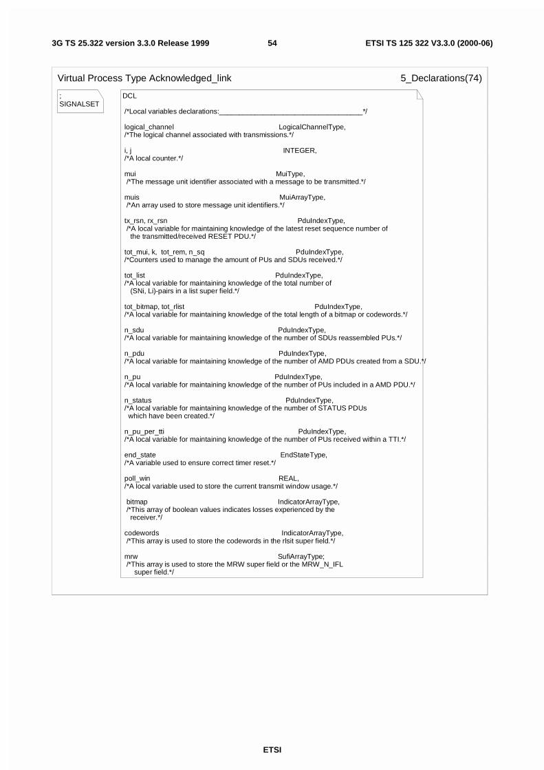
ETSI
ETSI TS 125 322 V3.3.0 (2000-06)543G TS 25.322 version 3.3.0 Release 1999
;SIGNALSET
Virtual Process Type Acknowledged_link 5_Declarations(74)
DCL
/*Local variables declarations:____________________________________*/ logical_channel LogicalChannelType, /*The logical channel associated with transmissions.*/
i, j INTEGER, /*A local counter.*/
mui MuiType, /*The message unit identifier associated with a message to be transmitted.*/
muis MuiArrayType, /*An array used to store message unit identifiers.*/ tx_rsn, rx_rsn PduIndexType, /*A local variable for maintaining knowledge of the latest reset sequence number of the transmitted/received RESET PDU.*/
tot_mui, k, tot_rem, n_sq PduIndexType, /*Counters used to manage the amount of PUs and SDUs received.*/
tot_list PduIndexType, /*A local variable for maintaining knowledge of the total number of (SNi, Li)-pairs in a list super field.*/
tot_bitmap, tot_rlist PduIndexType, /*A local variable for maintaining knowledge of the total length of a bitmap or codewords.*/ n_sdu PduIndexType, /*A local variable for maintaining knowledge of the number of SDUs reassembled PUs.*/
n_pdu PduIndexType, /*A local variable for maintaining knowledge of the number of AMD PDUs created from a SDU.*/ n_pu PduIndexType, /*A local variable for maintaining knowledge of the number of PUs included in a AMD PDU.*/
n_status PduIndexType, /*A local variable for maintaining knowledge of the number of STATUS PDUs which have been created.*/
n_pu_per_tti PduIndexType, /*A local variable for maintaining knowledge of the number of PUs received within a TTI.*/
end_state EndStateType, /*A variable used to ensure correct timer reset.*/
poll_win REAL, /*A local variable used to store the current transmit window usage.*/
bitmap IndicatorArrayType, /*This array of boolean values indicates losses experienced by the receiver.*/
codewords IndicatorArrayType, /*This array is used to store the codewords in the rlsit super field.*/
mrw SufiArrayType; /*This array is used to store the MRW super field or the MRW_N_IFL super field.*/
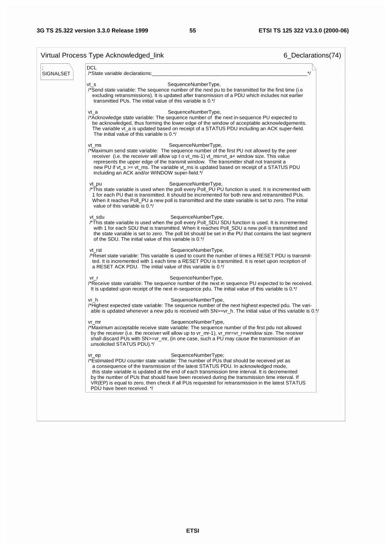
ETSI
ETSI TS 125 322 V3.3.0 (2000-06)553G TS 25.322 version 3.3.0 Release 1999
;SIGNALSET
Virtual Process Type Acknowledged_link 6_Declarations(74)
DCL /*State variable declarations:_______________________________________________________*/
vt_s SequenceNumberType, /*Send state variable: The sequence number of the next pu to be transmitted for the first time (i.e excluding retransmissions). It is updated after transmission of a PDU which includes not earlier transmitted PUs. The initial value of this variable is 0.*/
vt_a SequenceNumberType, /*Acknowledge state variable: The sequence number of the next in-sequence PU expected to be acknowledged, thus forming the lower edge of the window of acceptable acknowledgements. The variable vt_a is updated based on receipt of a STATUS PDU including an ACK super-field. The initial value of this variable is 0.*/
vt_ms SequenceNumberType, /*Maximum send state variable: The sequence number of the first PU not allowed by the peer receiver (i.e. the receiver will allow up t o vt_ms-1) vt_ms=vt_a+ window size. This value represents the upper edge of the transmit window. The transmitter shall not transmit a new PU if vt_s >= vt_ms. The variable vt_ms is updated based on receipt of a STATUS PDU incluiding an ACK and/or WINDOW super-field.*/
vt_pu SequenceNumberType, /*This state variable is used when the poll every Poll_PU PU function is used. It is incremented with 1 for each PU that is transmitted. It should be incremented for both new and retransmitted PUs. When it reaches Poll_PU a new poll is transmitted and the state variable is set to zero. The initial value of this variable is 0.*/
vt_sdu SequenceNumberType, /*This state variable is used when the poll every Poll_SDU SDU function is used. It is incremented with 1 for each SDU that is transmitted. When it reaches Poll_SDU a new poll is transmitted and the state variable is set to zero. The poll bit should be set in the PU that contains the last segment of the SDU. The initial value of this variable is 0.*/
vt_rst SequenceNumberType, /*Reset state variable: This variable is used to count the number of times a RESET PDU is transmit- ted. It is incremented with 1 each time a RESET PDU is transmitted. It is reset upon reception of a RESET ACK PDU. The initial value of this variable is 0.*/
vr_r SequenceNumberType, /*Receive state variable: The sequence number of the next in sequence PU expected to be received. It is updated upon receipt of the next in-sequence pdu. The initial value of this variable is 0.*/
vr_h SequenceNumberType, /*Highest expected state variable: The sequence number of the next highest expected pdu. The vari- able is updated whenever a new pdu is received with SN>=vr_h. The initial value of this variable is 0.*/
vr_mr SequenceNumberType, /*Maximum acceptable receive state variable: The sequence number of the first pdu not allowed by the receiver (i.e. the receiver will allow up to vr_mr-1), vr_mr=vr_r+window size. The receiver shall discard PUs with SN>=vr_mr, (in one case, such a PU may cause the transmission of an unsolicited STATUS PDU).*/
vr_ep SequenceNumberType; /*Estimated PDU counter state variable: The number of PUs that should be received yet as a consequence of the transmission of the latest STATUS PDU. In acknowledged mode, this state variable is updated at the end of each transmission time interval. It is decremented by the number of PUs that should have been received during the transmission time interval. If VR(EP) is equal to zero, then check if all PUs requested for retransmission in the latest STATUS PDU have been received. */
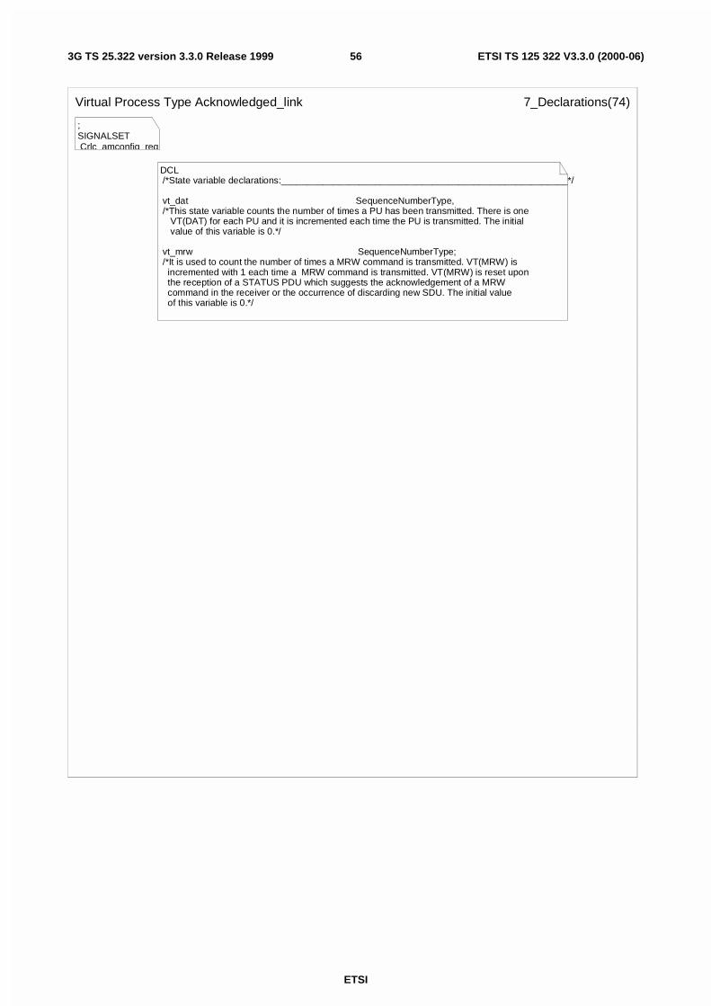
ETSI
ETSI TS 125 322 V3.3.0 (2000-06)563G TS 25.322 version 3.3.0 Release 1999
;SIGNALSET Crlc_amconfig_req,
Virtual Process Type Acknowledged_link 7_Declarations(74)
DCL /*State variable declarations:_______________________________________________________*/
vt_dat SequenceNumberType, /*This state variable counts the number of times a PU has been transmitted. There is one VT(DAT) for each PU and it is incremented each time the PU is transmitted. The initial value of this variable is 0.*/
vt_mrw SequenceNumberType; /*It is used to count the number of times a MRW command is transmitted. VT(MRW) is incremented with 1 each time a MRW command is transmitted. VT(MRW) is reset upon the reception of a STATUS PDU which suggests the acknowledgement of a MRW command in the receiver or the occurrence of discarding new SDU. The initial value of this variable is 0.*/
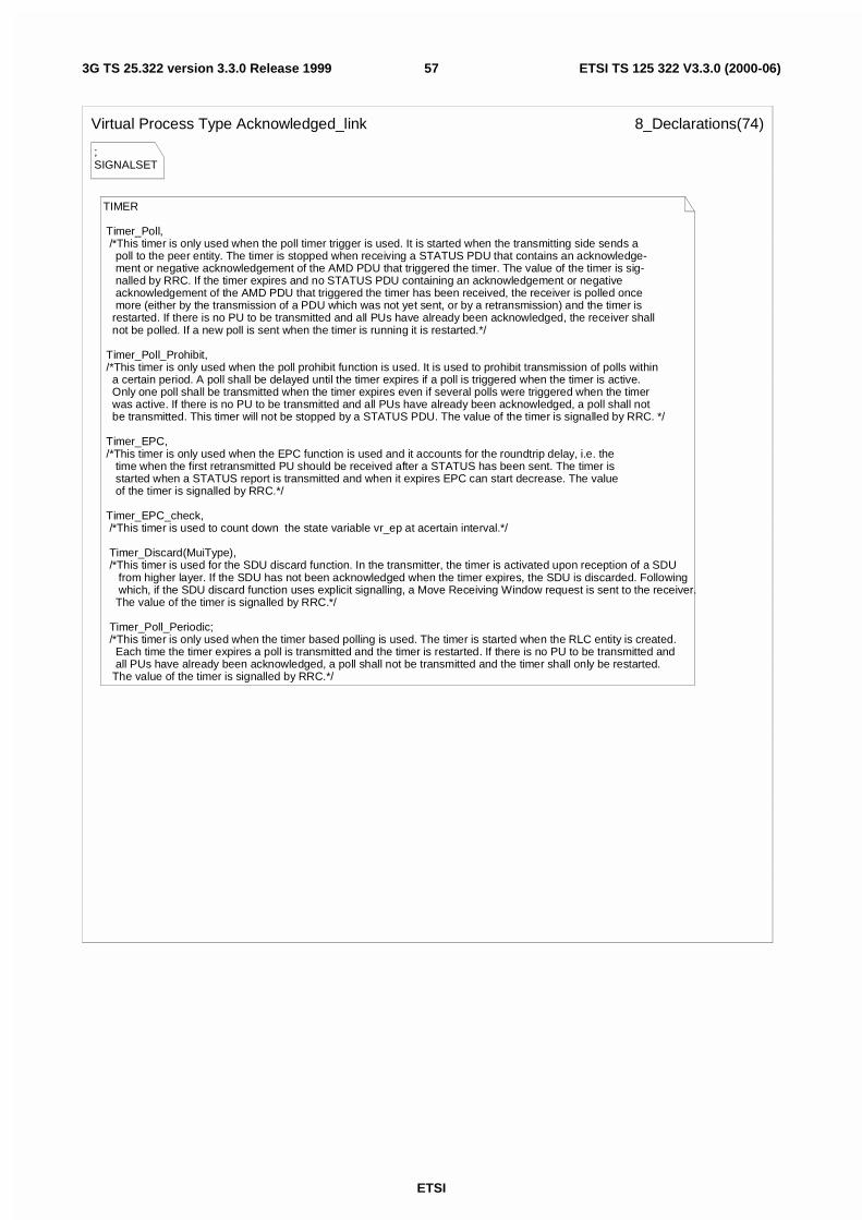
ETSI
ETSI TS 125 322 V3.3.0 (2000-06)573G TS 25.322 version 3.3.0 Release 1999
;SIGNALSET
Virtual Process Type Acknowledged_link 8_Declarations(74)
TIMER
Timer_Poll, /*This timer is only used when the poll timer trigger is used. It is started when the transmitting side sends a poll to the peer entity. The timer is stopped when receiving a STATUS PDU that contains an acknowledge- ment or negative acknowledgement of the AMD PDU that triggered the timer. The value of the timer is sig- nalled by RRC. If the timer expires and no STATUS PDU containing an acknowledgement or negative acknowledgement of the AMD PDU that triggered the timer has been received, the receiver is polled once more (either by the transmission of a PDU which was not yet sent, or by a retransmission) and the timer is restarted. If there is no PU to be transmitted and all PUs have already been acknowledged, the receiver shall not be polled. If a new poll is sent when the timer is running it is restarted.*/
Timer_Poll_Prohibit, /*This timer is only used when the poll prohibit function is used. It is used to prohibit transmission of polls within a certain period. A poll shall be delayed until the timer expires if a poll is triggered when the timer is active. Only one poll shall be transmitted when the timer expires even if several polls were triggered when the timer was active. If there is no PU to be transmitted and all PUs have already been acknowledged, a poll shall not be transmitted. This timer will not be stopped by a STATUS PDU. The value of the timer is signalled by RRC. */
Timer_EPC, /*This timer is only used when the EPC function is used and it accounts for the roundtrip delay, i.e. the time when the first retransmitted PU should be received after a STATUS has been sent. The timer is started when a STATUS report is transmitted and when it expires EPC can start decrease. The value of the timer is signalled by RRC.*/
Timer_EPC_check, /*This timer is used to count down the state variable vr_ep at acertain interval.*/
Timer_Discard(MuiType), /*This timer is used for the SDU discard function. In the transmitter, the timer is activated upon reception of a SDU from higher layer. If the SDU has not been acknowledged when the timer expires, the SDU is discarded. Following which, if the SDU discard function uses explicit signalling, a Move Receiving Window request is sent to the receiver. The value of the timer is signalled by RRC.*/
Timer_Poll_Periodic; /*This timer is only used when the timer based polling is used. The timer is started when the RLC entity is created. Each time the timer expires a poll is transmitted and the timer is restarted. If there is no PU to be transmitted and all PUs have already been acknowledged, a poll shall not be transmitted and the timer shall only be restarted. The value of the timer is signalled by RRC.*/
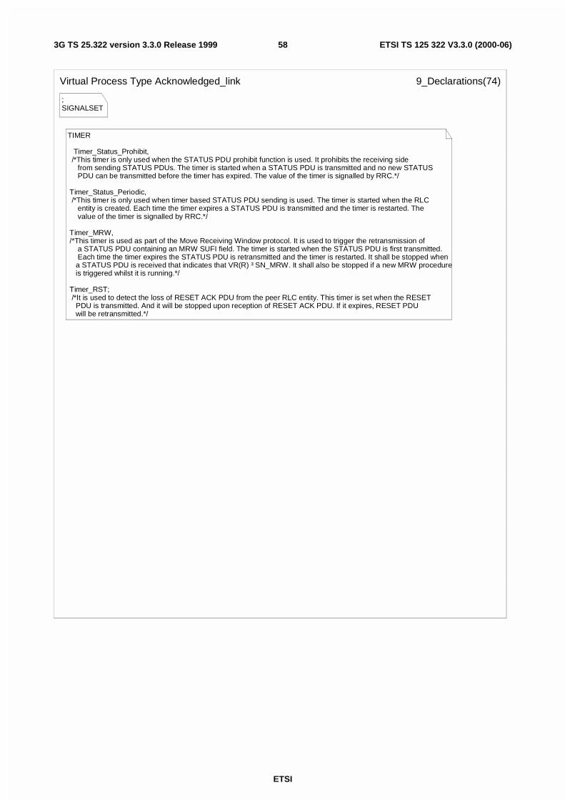
ETSI
ETSI TS 125 322 V3.3.0 (2000-06)583G TS 25.322 version 3.3.0 Release 1999
;SIGNALSET
Virtual Process Type Acknowledged_link 9_Declarations(74)
TIMER
Timer_Status_Prohibit, /*This timer is only used when the STATUS PDU prohibit function is used. It prohibits the receiving side from sending STATUS PDUs. The timer is started when a STATUS PDU is transmitted and no new STATUS PDU can be transmitted before the timer has expired. The value of the timer is signalled by RRC.*/
Timer_Status_Periodic, /*This timer is only used when timer based STATUS PDU sending is used. The timer is started when the RLC entity is created. Each time the timer expires a STATUS PDU is transmitted and the timer is restarted. The value of the timer is signalled by RRC.*/
Timer_MRW, /*This timer is used as part of the Move Receiving Window protocol. It is used to trigger the retransmission of a STATUS PDU containing an MRW SUFI field. The timer is started when the STATUS PDU is first transmitted. Each time the timer expires the STATUS PDU is retransmitted and the timer is restarted. It shall be stopped when a STATUS PDU is received that indicates that VR(R) ³ SN_MRW. It shall also be stopped if a new MRW procedure is triggered whilst it is running.*/
Timer_RST; /*It is used to detect the loss of RESET ACK PDU from the peer RLC entity. This timer is set when the RESET PDU is transmitted. And it will be stopped upon reception of RESET ACK PDU. If it expires, RESET PDU will be retransmitted.*/
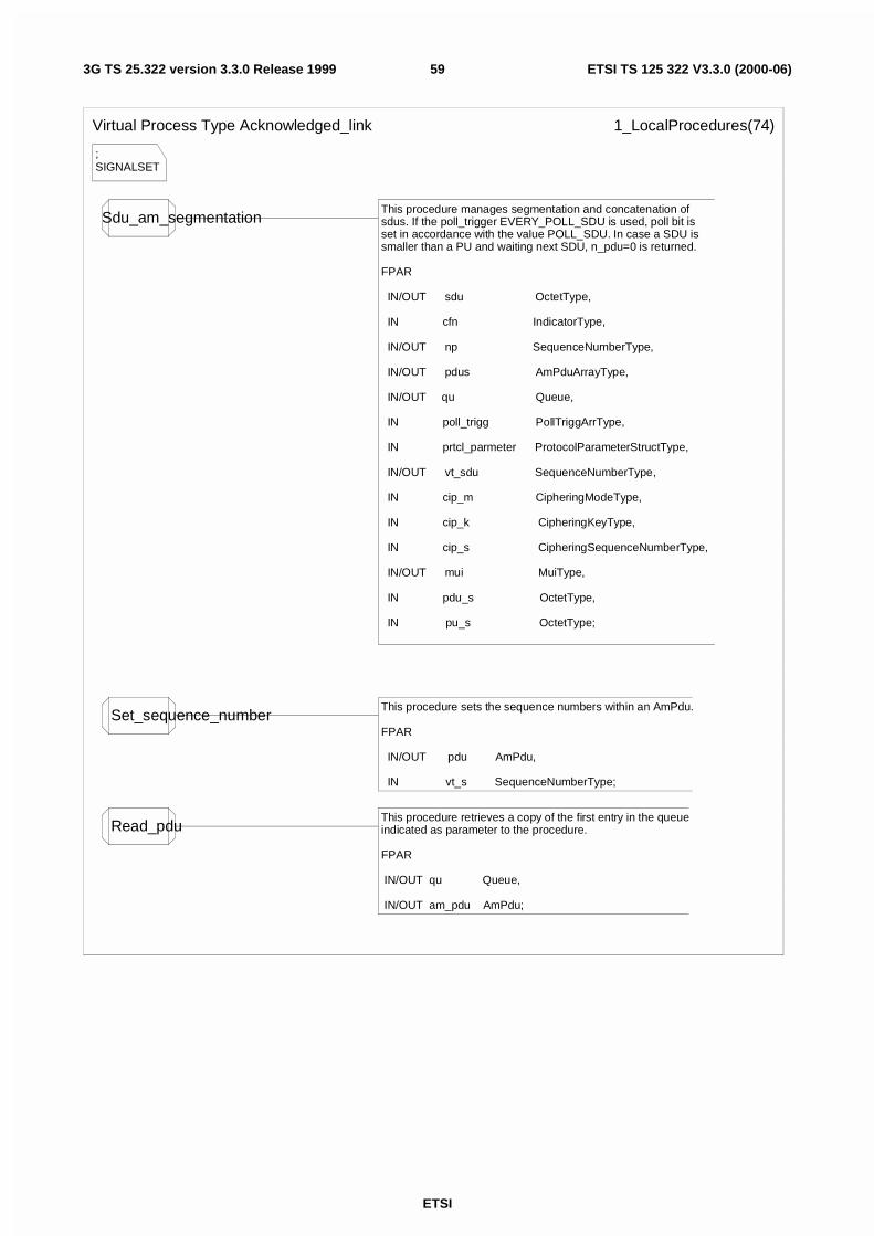
ETSI
ETSI TS 125 322 V3.3.0 (2000-06)593G TS 25.322 version 3.3.0 Release 1999
;SIGNALSET
Virtual Process Type Acknowledged_link 1_LocalProcedures(74)
Sdu_am_segmentationThis procedure manages segmentation and concatenation ofsdus. If the poll_trigger EVERY_POLL_SDU is used, poll bit is set in accordance with the value POLL_SDU. In case a SDU is smaller than a PU and waiting next SDU, n_pdu=0 is returned.
FPAR
IN/OUT sdu OctetType,
IN cfn IndicatorType,
IN/OUT np SequenceNumberType,
IN/OUT pdus AmPduArrayType,
IN/OUT qu Queue,
IN poll_trigg PollTriggArrType,
IN prtcl_parmeter ProtocolParameterStructType,
IN/OUT vt_sdu SequenceNumberType,
IN cip_m CipheringModeType,
IN cip_k CipheringKeyType,
IN cip_s CipheringSequenceNumberType,
IN/OUT mui MuiType,
IN pdu_s OctetType,
IN pu_s OctetType;
Set_sequence_numberThis procedure sets the sequence numbers within an AmPdu.
FPAR
IN/OUT pdu AmPdu,
IN vt_s SequenceNumberType;
Read_pduThis procedure retrieves a copy of the first entry in the queue indicated as parameter to the procedure.
FPAR
IN/OUT qu Queue,
IN/OUT am_pdu AmPdu;
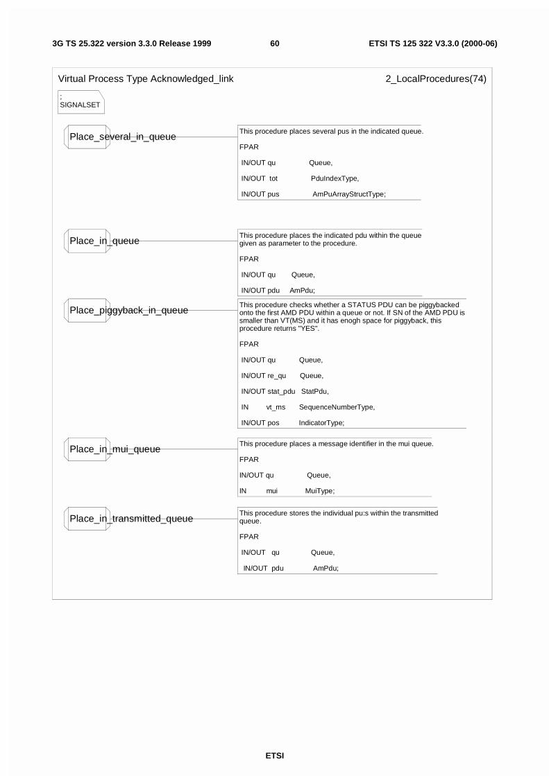
ETSI
ETSI TS 125 322 V3.3.0 (2000-06)603G TS 25.322 version 3.3.0 Release 1999
;SIGNALSET
Virtual Process Type Acknowledged_link 2_LocalProcedures(74)
Place_several_in_queueThis procedure places several pus in the indicated queue.
FPAR
IN/OUT qu Queue,
IN/OUT tot PduIndexType,
IN/OUT pus AmPuArrayStructType;
Place_in_queueThis procedure places the indicated pdu within the queue given as parameter to the procedure.
FPAR
IN/OUT qu Queue,
IN/OUT pdu AmPdu;
Place_piggyback_in_queueThis procedure checks whether a STATUS PDU can be piggybacked onto the first AMD PDU within a queue or not. If SN of the AMD PDU is smaller than VT(MS) and it has enogh space for piggyback, this procedure returns "YES".
FPAR
IN/OUT qu Queue,
IN/OUT re_qu Queue,
IN/OUT stat_pdu StatPdu,
IN vt_ms SequenceNumberType,
IN/OUT pos IndicatorType;
Place_in_mui_queueThis procedure places a message identifier in the mui queue.
FPAR
IN/OUT qu Queue,
IN mui MuiType;
Place_in_transmitted_queueThis procedure stores the individual pu:s within the transmittedqueue.
FPAR
IN/OUT qu Queue,
IN/OUT pdu AmPdu;
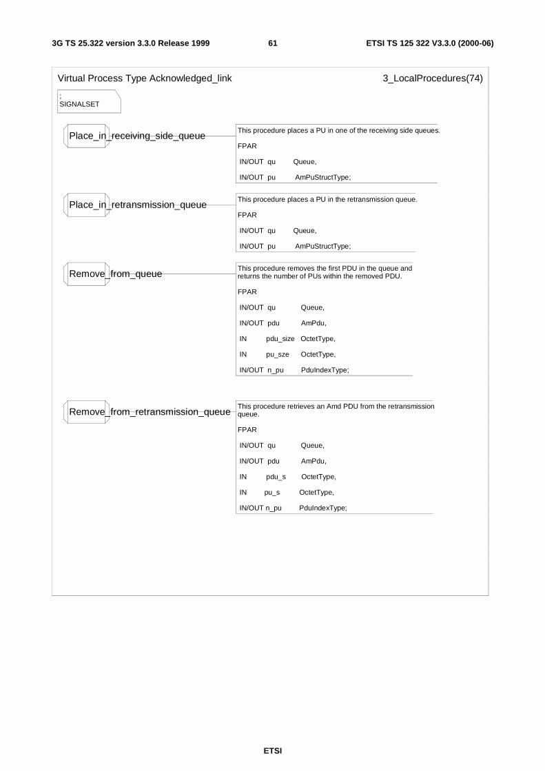
ETSI
ETSI TS 125 322 V3.3.0 (2000-06)613G TS 25.322 version 3.3.0 Release 1999
;SIGNALSET
Virtual Process Type Acknowledged_link 3_LocalProcedures(74)
Place_in_receiving_side_queueThis procedure places a PU in one of the receiving side queues.
FPAR
IN/OUT qu Queue,
IN/OUT pu AmPuStructType;
Place_in_retransmission_queueThis procedure places a PU in the retransmission queue.
FPAR
IN/OUT qu Queue,
IN/OUT pu AmPuStructType;
Remove_from_queueThis procedure removes the first PDU in the queue and returns the number of PUs within the removed PDU.
FPAR
IN/OUT qu Queue,
IN/OUT pdu AmPdu,
IN pdu_size OctetType,
IN pu_sze OctetType,
IN/OUT n_pu PduIndexType;
Remove_from_retransmission_queueThis procedure retrieves an Amd PDU from the retransmissionqueue.
FPAR
IN/OUT qu Queue,
IN/OUT pdu AmPdu,
IN pdu_s OctetType,
IN pu_s OctetType,
IN/OUT n_pu PduIndexType;
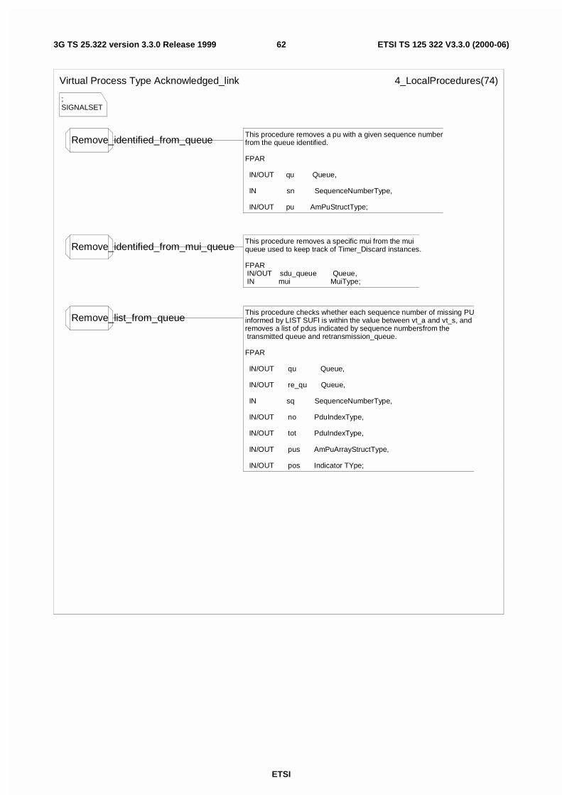
ETSI
ETSI TS 125 322 V3.3.0 (2000-06)623G TS 25.322 version 3.3.0 Release 1999
;SIGNALSET
Virtual Process Type Acknowledged_link 4_LocalProcedures(74)
Remove_identified_from_queueThis procedure removes a pu with a given sequence number from the queue identified.
FPAR
IN/OUT qu Queue,
IN sn SequenceNumberType,
IN/OUT pu AmPuStructType;
Remove_identified_from_mui_queueThis procedure removes a specific mui from the mui queue used to keep track of Timer_Discard instances.
FPAR IN/OUT sdu_queue Queue, IN mui MuiType;
Remove_list_from_queueThis procedure checks whether each sequence number of missing PU informed by LIST SUFI is within the value between vt_a and vt_s, and removes a list of pdus indicated by sequence numbersfrom the transmitted queue and retransmission_queue.
FPAR
IN/OUT qu Queue,
IN/OUT re_qu Queue,
IN sq SequenceNumberType,
IN/OUT no PduIndexType,
IN/OUT tot PduIndexType,
IN/OUT pus AmPuArrayStructType,
IN/OUT pos Indicator TYpe;
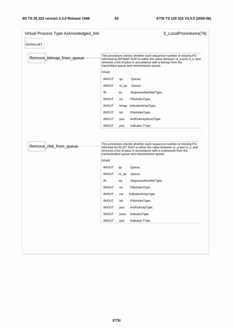
ETSI
ETSI TS 125 322 V3.3.0 (2000-06)633G TS 25.322 version 3.3.0 Release 1999
;SIGNALSET
Virtual Process Type Acknowledged_link 5_LocalProcedures(74)
Remove_bitmap_from_queueThis procedure checks whether each sequence number of missing PU informed by BITMAP SUFI is within the value between vt_a and vt_s, and removes a list of pdus in accordance with a bitmap from the transmitted queue and retranmission queue.
FPAR
IN/OUT qu Queue,
IN/OUT re_qu Queue,
IN sq SequenceNumberType,
IN/OUT no PduIndexType,
IN/OUT bmap IndicatorArrayType,
IN/OUT tot PduIndexType,
IN/OUT pus AmPuArrayStructType,
IN/OUT pos Indicator TYpe;
Remove_rlist_from_queueThis procedure checks whether each sequence number of missing PU informed by RLIST SUFI is within the value between vt_a and vt_s, and removes a list of pdus in accordance with a codewords from the transmissitted queue and retranmission queue.
FPAR
IN/OUT qu Queue,
IN/OUT re_qu Queue,
IN sq SequenceNumberType,
IN/OUT no PduIndexType,
IN/OUT cw IndicatorArrayType,
IN/OUT tot PduIndexType,
IN/OUT pus AmPuArrayType,
IN/OUT poss IndicatorType,
IN/OUT pos Indicator TYpe;
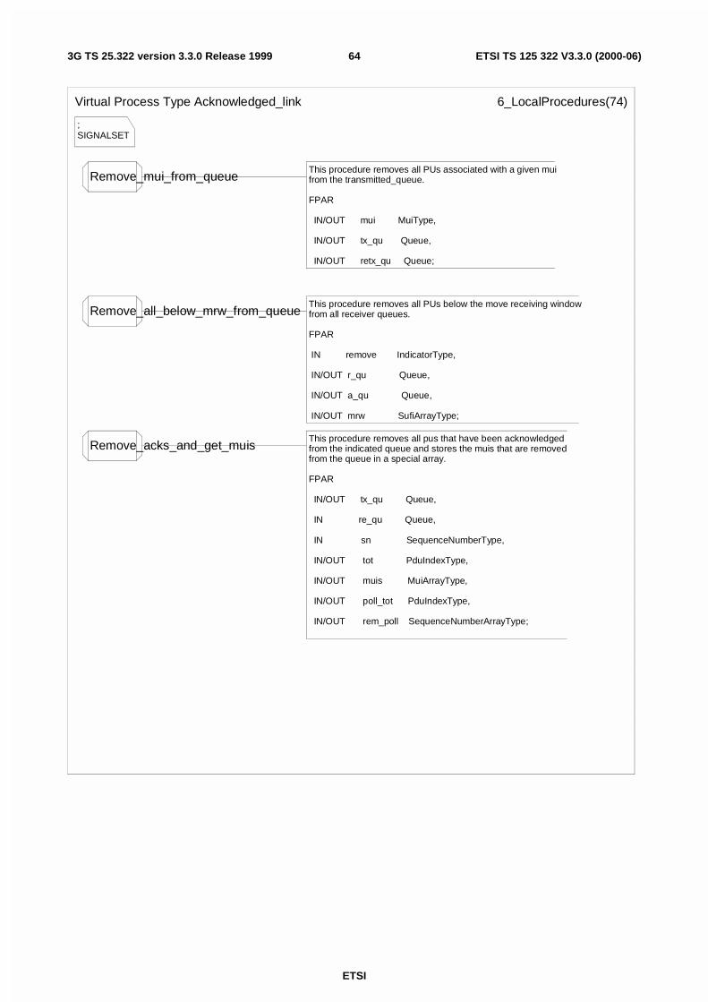
ETSI
ETSI TS 125 322 V3.3.0 (2000-06)643G TS 25.322 version 3.3.0 Release 1999
;SIGNALSET
Virtual Process Type Acknowledged_link 6_LocalProcedures(74)
Remove_mui_from_queueThis procedure removes all PUs associated with a given muifrom the transmitted_queue.
FPAR
IN/OUT mui MuiType,
IN/OUT tx_qu Queue,
IN/OUT retx_qu Queue;
Remove_all_below_mrw_from_queueThis procedure removes all PUs below the move receiving windowfrom all receiver queues.
FPAR IN remove IndicatorType,
IN/OUT r_qu Queue,
IN/OUT a_qu Queue,
IN/OUT mrw SufiArrayType;
Remove_acks_and_get_muisThis procedure removes all pus that have been acknowledged from the indicated queue and stores the muis that are removed from the queue in a special array.
FPAR
IN/OUT tx_qu Queue,
IN re_qu Queue,
IN sn SequenceNumberType,
IN/OUT tot PduIndexType,
IN/OUT muis MuiArrayType,
IN/OUT poll_tot PduIndexType,
IN/OUT rem_poll SequenceNumberArrayType;
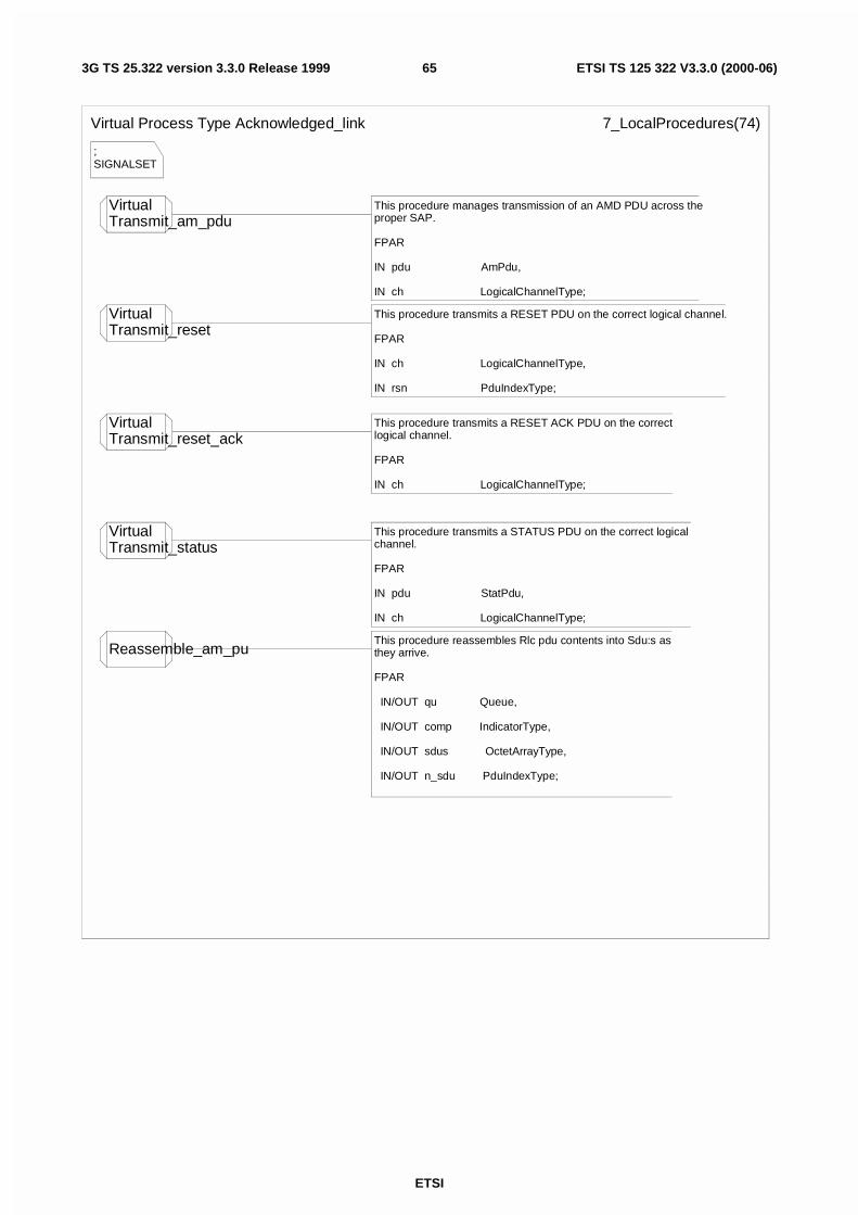
ETSI
ETSI TS 125 322 V3.3.0 (2000-06)653G TS 25.322 version 3.3.0 Release 1999
;SIGNALSET
Virtual Process Type Acknowledged_link 7_LocalProcedures(74)
VirtualTransmit_am_pdu
This procedure manages transmission of an AMD PDU across theproper SAP.
FPAR
IN pdu AmPdu,
IN ch LogicalChannelType;
VirtualTransmit_reset
This procedure transmits a RESET PDU on the correct logical channel.
FPAR
IN ch LogicalChannelType,
IN rsn PduIndexType;
VirtualTransmit_reset_ack
This procedure transmits a RESET ACK PDU on the correctlogical channel.
FPAR
IN ch LogicalChannelType;
VirtualTransmit_status
This procedure transmits a STATUS PDU on the correct logical channel.
FPAR
IN pdu StatPdu,
IN ch LogicalChannelType;
Reassemble_am_puThis procedure reassembles Rlc pdu contents into Sdu:s as they arrive.
FPAR
IN/OUT qu Queue,
IN/OUT comp IndicatorType,
IN/OUT sdus OctetArrayType,
IN/OUT n_sdu PduIndexType;
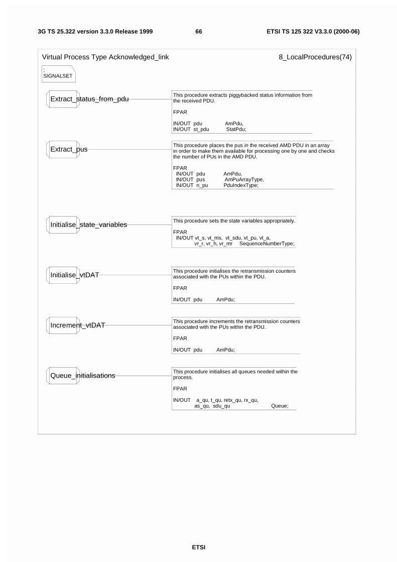
ETSI
ETSI TS 125 322 V3.3.0 (2000-06)663G TS 25.322 version 3.3.0 Release 1999
;SIGNALSET
Virtual Process Type Acknowledged_link 8_LocalProcedures(74)
Extract_status_from_pduThis procedure extracts piggybacked status information from the received PDU.
FPAR
IN/OUT pdu AmPdu,IN/OUT st_pdu StatPdu;
Extract_pusThis procedure places the pus in the received AMD PDU in an array in order to make them available for processing one by one and checks the number of PUs in the AMD PDU.
FPAR IN/OUT pdu AmPdu, IN/OUT pus AmPuArrayType, IN/OUT n_pu PduIndexType;
Initialise_state_variablesThis procedure sets the state variables appropriately.
FPAR IN/OUT vt_s, vt_ms, vt_sdu, vt_pu, vt_a, vr_r, vr_h, vr_mr SequenceNumberType;
Initialise_vtDATThis procedure initialises the retransmission countersassociated with the PUs within the PDU.
FPAR
IN/OUT pdu AmPdu;
Increment_vtDATThis procedure increments the retransmission counters associated with the PUs within the PDU.
FPAR
IN/OUT pdu AmPdu;
Queue_initialisationsThis procedure initialises all queues needed within theprocess.
FPAR
IN/OUT a_qu, t_qu, retx_qu, rx_qu, as_qu, sdu_qu Queue;
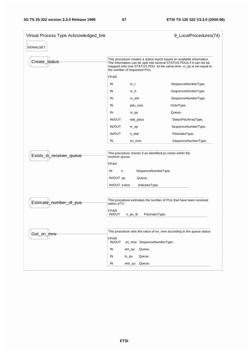
ETSI
ETSI TS 125 322 V3.3.0 (2000-06)673G TS 25.322 version 3.3.0 Release 1999
;SIGNALSET
Virtual Process Type Acknowledged_link 9_LocalProcedures(74)
Create_statusThis procedure creates a status report based on available information.The information can be split into several STATUS PDUs if it can not be mapped onto one STATUS PDU. At the same time, vr_ep is set equal to the number of requested PUs.
FPAR
IN vr_r SequenceNumberType,
IN vr_h SequenceNumberType,
IN rx_win SequenceNumberType,
IN pdu_size OctetType,
IN rx_qu Queue,
IN/OUT stat_pdus StatusPduArrayType,
IN/OUT vr_ep SequenceNumberType,
IN/OUT n_stat PduIndexType,
IN sn_mrw SequenceNumberType;
Exists_in_receiver_queueThis procedure checks if an identified pu exists within thereceiver queue.
FPAR
IN n SequenceNumberType,
IN/OUT qu Queue,
IN/OUT exists IndicatorType;
Estimate_number_of_pusThis procedure estimates the number of PUs that have been receivedwithin aTTI.
FPAR IN/OUT n_pu_tti PduIndexType;
Get_sn_mrwThis procedure sets the value of sn_mrw according to the queue status.
FPAR IN/OUT sn_mrw SequenceNumberType,
IN am_qu Queue,
IN tx_qu Queue,
IN retx_qu Queue;
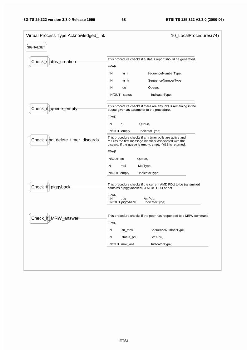
ETSI
ETSI TS 125 322 V3.3.0 (2000-06)683G TS 25.322 version 3.3.0 Release 1999
;SIGNALSET
Virtual Process Type Acknowledged_link 10_LocalProcedures(74)
Check_status_creationThis procedure checks if a status report should be generated.
FPAR
IN vr_r SequenceNumberType,
IN vr_h SequenceNumberType,
IN qu Queue,
IN/OUT status IndicatorType;
Check_if_queue_emptyThis procedure checks if there are any PDUs remaining in thequeue given as parameter to the procedure.
FPAR
IN qu Queue,
IN/OUT empty IndicatorType;
Check_and_delete_timer_discardsThis procedure checks if any timer polls are active andreturns the first message identifier associated with thediscard. If the queue is empty, empty=YES is returned.
FPAR
IN/OUT qu Queue,
IN mui MuiType,
IN/OUT empty IndicatorType;
Check_if_piggybackThis procedure checks if the current AMD PDU to be transmitted contains a piggybacked STATUS PDU or not
FPAR IN pdu AmPdu, IN/OUT piggyback IndicatorType;
Check_if_MRW_answerThis procedure checks if the peer has responded to a MRW command.
FPAR
IN sn_mrw SequenceNumberType,
IN status_pdu StatPdu,
IN/OUT mrw_ans IndicatorType;
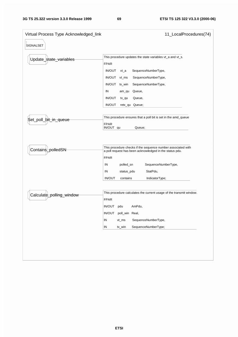
ETSI
ETSI TS 125 322 V3.3.0 (2000-06)693G TS 25.322 version 3.3.0 Release 1999
;SIGNALSET
Virtual Process Type Acknowledged_link 11_LocalProcedures(74)
Update_state_variablesThis procedure updates the state variables vt_a and vt_s.
FPAR
IN/OUT vt_a SequenceNumberType,
IN/OUT vt_ms SequenceNumberType,
IN/OUT tx_win SequenceNumberType,
IN am_qu Queue,
IN/OUT tx_qu Queue,
IN/OUT retx_qu Queue;
Set_poll_bit_in_queueThis procedure ensures that a poll bit is set in the amd_queue
FPARIN/OUT qu Queue;
Contains_polledSNThis procedure checks if the sequence number associated witha poll request has been acknowledged in the status pdu.
FPAR
IN polled_sn SequenceNumberType,
IN status_pdu StatPdu,
IN/OUT contains IndicatorType;
Calculate_polling_windowThis procedure calculates the current usage of the transmit window.
FPAR
IN/OUT pdu AmPdu,
IN/OUT poll_win Real,
IN vt_ms SequenceNumberType,
IN tx_win SequenceNumberType;
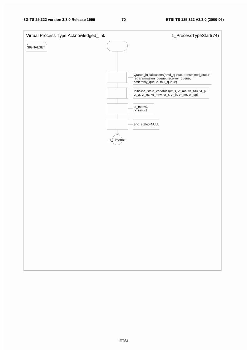
ETSI
ETSI TS 125 322 V3.3.0 (2000-06)703G TS 25.322 version 3.3.0 Release 1999
;SIGNALSET
Virtual Process Type Acknowledged_link 1_ProcessTypeStart(74)
Queue_initialisations(amd_queue, transmitted_queue, retransmission_queue, receiver_queue, assembly_queue, mui_queue)
Initialise_state_variables(vt_s, vt_ms, vt_sdu, vt_pu, vt_a, vt_rst, vt_mrw, vr_r, vr_h, vr_mr, vr_ep)
tx_rsn:=0, rx_rsn:=1
end_state:=NULL
1_TimerInit
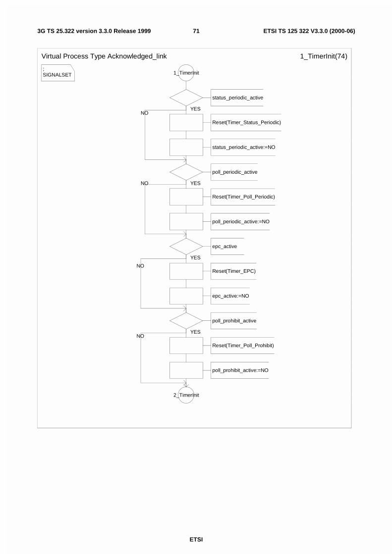
ETSI
ETSI TS 125 322 V3.3.0 (2000-06)713G TS 25.322 version 3.3.0 Release 1999
;SIGNALSET
Virtual Process Type Acknowledged_link 1_TimerInit(74)
1_TimerInit
status_periodic_active
Reset(Timer_Status_Periodic)
status_periodic_active:=NO
poll_periodic_active
Reset(Timer_Poll_Periodic)
poll_periodic_active:=NO
epc_active
Reset(Timer_EPC)
epc_active:=NO
poll_prohibit_active
Reset(Timer_Poll_Prohibit)
poll_prohibit_active:=NO
2_TimerInit
YES
YES
YES
YESNO
NO
NO
NO
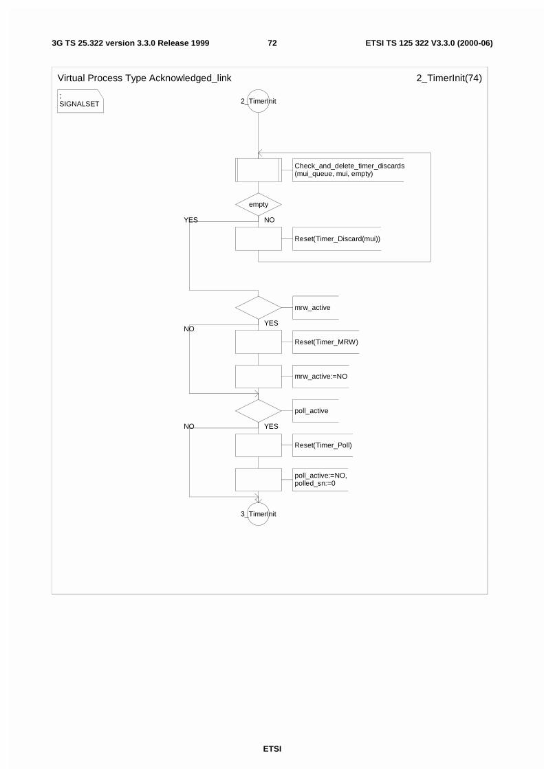
ETSI
ETSI TS 125 322 V3.3.0 (2000-06)723G TS 25.322 version 3.3.0 Release 1999
;SIGNALSET
Virtual Process Type Acknowledged_link 2_TimerInit(74)
2_TimerInit
Check_and_delete_timer_discards(mui_queue, mui, empty)
empty
Reset(Timer_Discard(mui))
mrw_active
Reset(Timer_MRW)
mrw_active:=NO
poll_active
Reset(Timer_Poll)
poll_active:=NO,polled_sn:=0
3_TimerInit
NOYES
YES
YESNO
NO
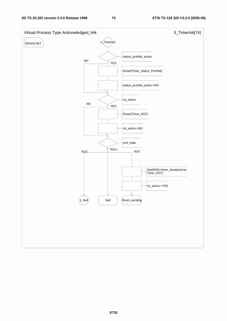
ETSI
ETSI TS 125 322 V3.3.0 (2000-06)733G TS 25.322 version 3.3.0 Release 1999
;SIGNALSET
Virtual Process Type Acknowledged_link 3_TimerInit(74)
3_TimerInit
status_prohibit_active
Reset(Timer_Status_Prohibit)
status_prohibit_active:=NO
rst_active
Reset(Timer_RST)
rst_active:=NO
end_state
Set(NOW+timer_durations!rst,Timer_RST)
rst_active:=YES
Reset_pending1_Null Null
YES
YES
RSTACKNULL
NO
NO
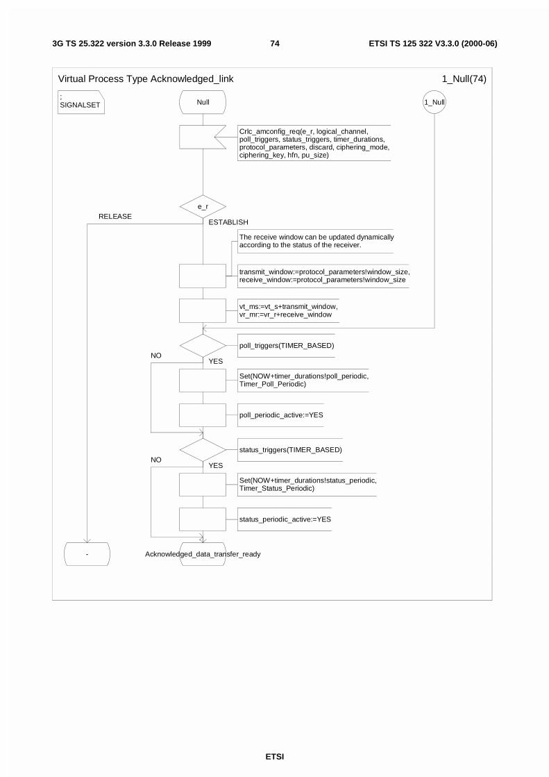
ETSI
ETSI TS 125 322 V3.3.0 (2000-06)743G TS 25.322 version 3.3.0 Release 1999
;SIGNALSET
Virtual Process Type Acknowledged_link 1_Null(74)
Null
Crlc_amconfig_req(e_r, logical_channel, poll_triggers, status_triggers, timer_durations, protocol_parameters, discard, ciphering_mode, ciphering_key, hfn, pu_size)
e_r
The receive window can be updated dynamicallyaccording to the status of the receiver.
transmit_window:=protocol_parameters!window_size,receive_window:=protocol_parameters!window_size
vt_ms:=vt_s+transmit_window,vr_mr:=vr_r+receive_window
poll_triggers(TIMER_BASED)
Set(NOW+timer_durations!poll_periodic,Timer_Poll_Periodic)
poll_periodic_active:=YES
status_triggers(TIMER_BASED)
Set(NOW+timer_durations!status_periodic,Timer_Status_Periodic)
status_periodic_active:=YES
Acknowledged_data_transfer_ready-
1_Null
ESTABLISH
YES
YESNO
NO
RELEASE
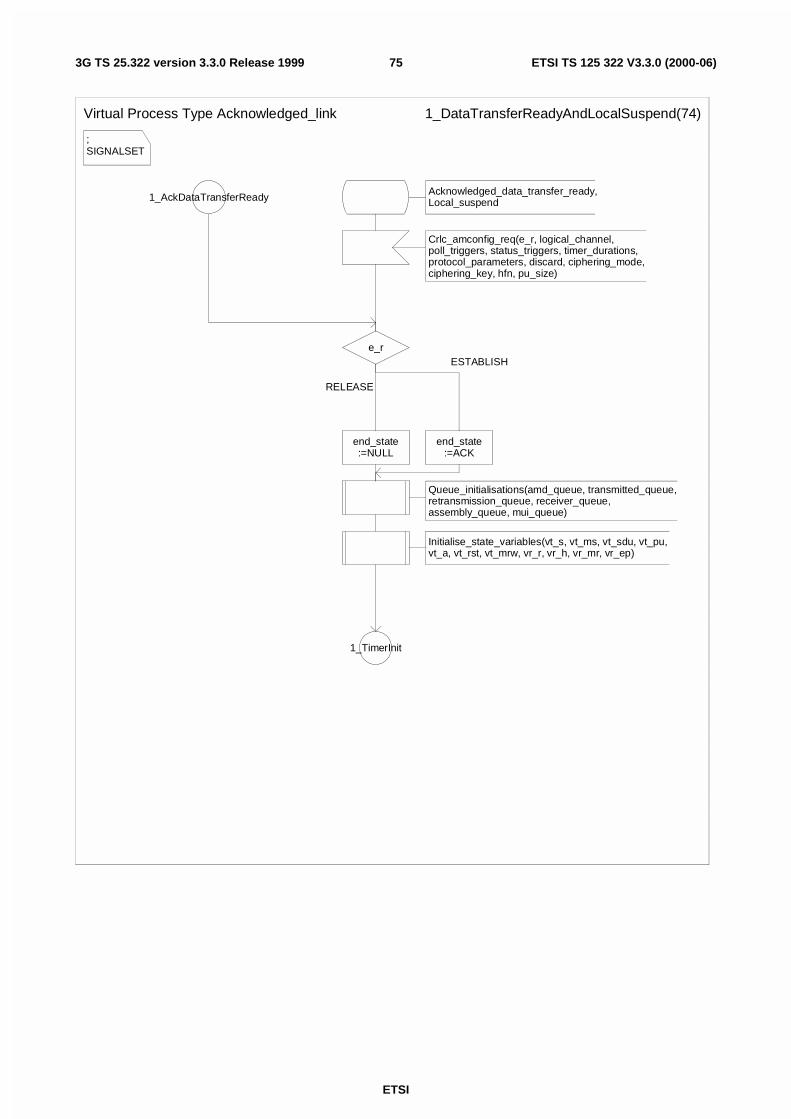
ETSI
ETSI TS 125 322 V3.3.0 (2000-06)753G TS 25.322 version 3.3.0 Release 1999
;SIGNALSET
Virtual Process Type Acknowledged_link 1_DataTransferReadyAndLocalSuspend(74)
1_AckDataTransferReady
e_r
end_state:=NULL
Queue_initialisations(amd_queue, transmitted_queue, retransmission_queue, receiver_queue, assembly_queue, mui_queue)
Initialise_state_variables(vt_s, vt_ms, vt_sdu, vt_pu, vt_a, vt_rst, vt_mrw, vr_r, vr_h, vr_mr, vr_ep)
1_TimerInit
end_state:=ACK
Acknowledged_data_transfer_ready,Local_suspend
Crlc_amconfig_req(e_r, logical_channel, poll_triggers, status_triggers, timer_durations, protocol_parameters, discard, ciphering_mode, ciphering_key, hfn, pu_size)
RELEASE
ESTABLISH
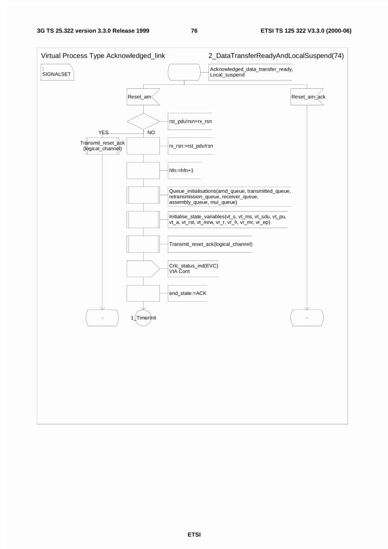
ETSI
ETSI TS 125 322 V3.3.0 (2000-06)763G TS 25.322 version 3.3.0 Release 1999
;SIGNALSET
Virtual Process Type Acknowledged_link 2_DataTransferReadyAndLocalSuspend(74)
Acknowledged_data_transfer_ready,Local_suspend
Reset_am
rst_pdu!rsn=rx_rsn
Transmit_reset_ack(logical_channel)
-
rx_rsn:=rst_pdu!rsn
hfn:=hfn+1
Queue_initialisations(amd_queue, transmitted_queue, retransmission_queue, receiver_queue, assembly_queue, mui_queue)
Initialise_state_variables(vt_s, vt_ms, vt_sdu, vt_pu, vt_a, vt_rst, vt_mrw, vr_r, vr_h, vr_mr, vr_ep)
Transmit_reset_ack(logical_channel)
Crlc_status_ind(EVC)VIA Cont
end_state:=ACK
1_TimerInit
Reset_am_ack
-
YES NO
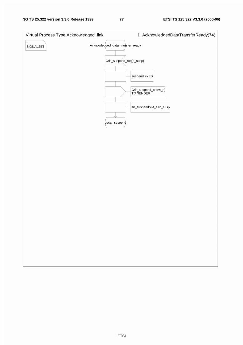
ETSI
ETSI TS 125 322 V3.3.0 (2000-06)773G TS 25.322 version 3.3.0 Release 1999
;SIGNALSET
Virtual Process Type Acknowledged_link 1_AcknowledgedDataTransferReady(74)
Acknowledged_data_transfer_ready
Crlc_suspend_req(n_susp)
suspend:=YES
Crlc_suspend_cnf(vt_s)TO SENDER
sn_suspend:=vt_s+n_susp
Local_suspend
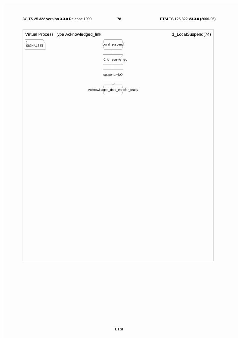
ETSI
ETSI TS 125 322 V3.3.0 (2000-06)783G TS 25.322 version 3.3.0 Release 1999
;SIGNALSET
Virtual Process Type Acknowledged_link 1_LocalSuspend(74)
Local_suspend
Crlc_resume_req
suspend:=NO
Acknowledged_data_transfer_ready
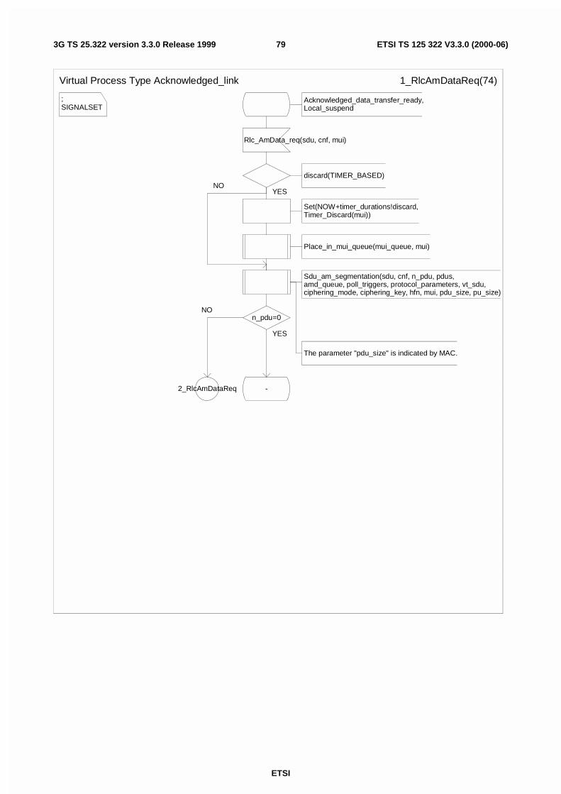
ETSI
ETSI TS 125 322 V3.3.0 (2000-06)793G TS 25.322 version 3.3.0 Release 1999
;SIGNALSET
Virtual Process Type Acknowledged_link 1_RlcAmDataReq(74)
Acknowledged_data_transfer_ready,Local_suspend
Rlc_AmData_req(sdu, cnf, mui)
discard(TIMER_BASED)
Set(NOW+timer_durations!discard,Timer_Discard(mui))
Place_in_mui_queue(mui_queue, mui)
Sdu_am_segmentation(sdu, cnf, n_pdu, pdus, amd_queue, poll_triggers, protocol_parameters, vt_sdu, ciphering_mode, ciphering_key, hfn, mui, pdu_size, pu_size)
The parameter "pdu_size" is indicated by MAC.
n_pdu=0
2_RlcAmDataReq -
YES
NO
YES
NO
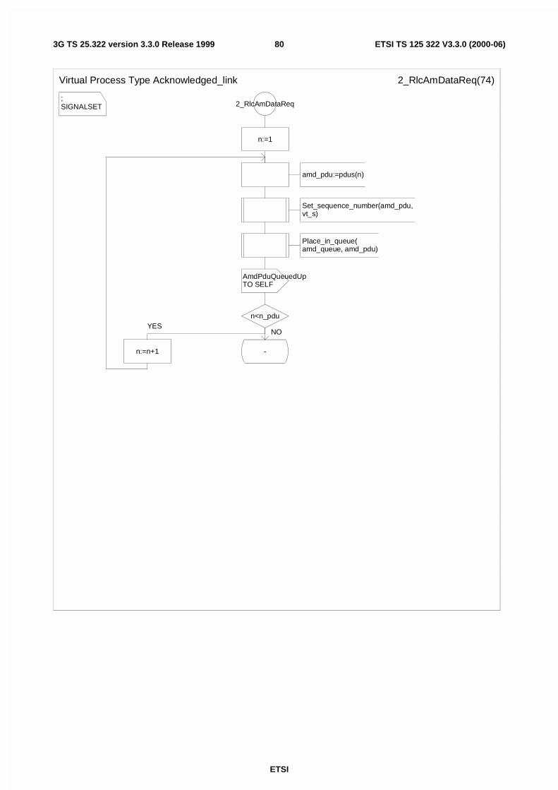
ETSI
ETSI TS 125 322 V3.3.0 (2000-06)803G TS 25.322 version 3.3.0 Release 1999
;SIGNALSET
Virtual Process Type Acknowledged_link 2_RlcAmDataReq(74)
2_RlcAmDataReq
n:=1
amd_pdu:=pdus(n)
Set_sequence_number(amd_pdu, vt_s)
Place_in_queue(amd_queue, amd_pdu)
AmdPduQueuedUpTO SELF
n<n_pdu
n:=n+1 -
YESNO
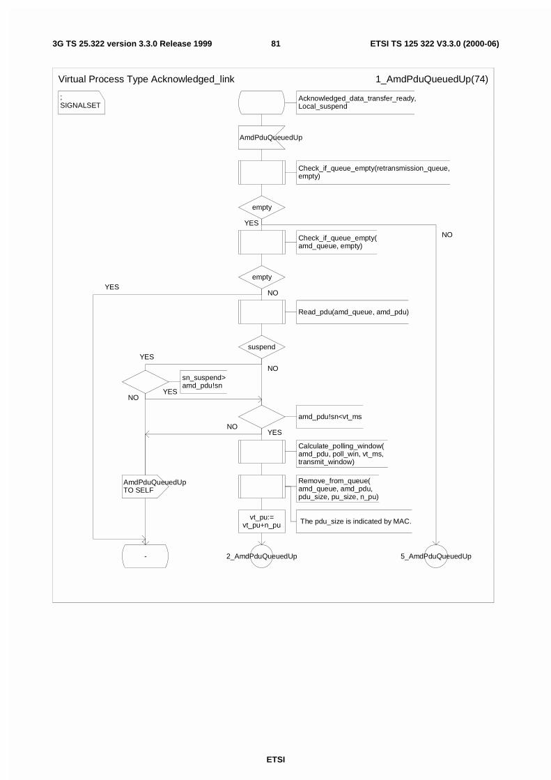
ETSI
ETSI TS 125 322 V3.3.0 (2000-06)813G TS 25.322 version 3.3.0 Release 1999
;SIGNALSET
Virtual Process Type Acknowledged_link 1_AmdPduQueuedUp(74)
Acknowledged_data_transfer_ready,Local_suspend
AmdPduQueuedUp
Check_if_queue_empty(retransmission_queue, empty)
empty
Check_if_queue_empty(amd_queue, empty)
empty
Read_pdu(amd_queue, amd_pdu)
suspend
sn_suspend>amd_pdu!sn
amd_pdu!sn<vt_ms
Calculate_polling_window(amd_pdu, poll_win, vt_ms, transmit_window)
Remove_from_queue(amd_queue, amd_pdu, pdu_size, pu_size, n_pu)
The pdu_size is indicated by MAC.vt_pu:=vt_pu+n_pu
2_AmdPduQueuedUp
AmdPduQueuedUpTO SELF
- 5_AmdPduQueuedUp
YES
NO
YES
YES
YESNO
NO
NO
YES
NO
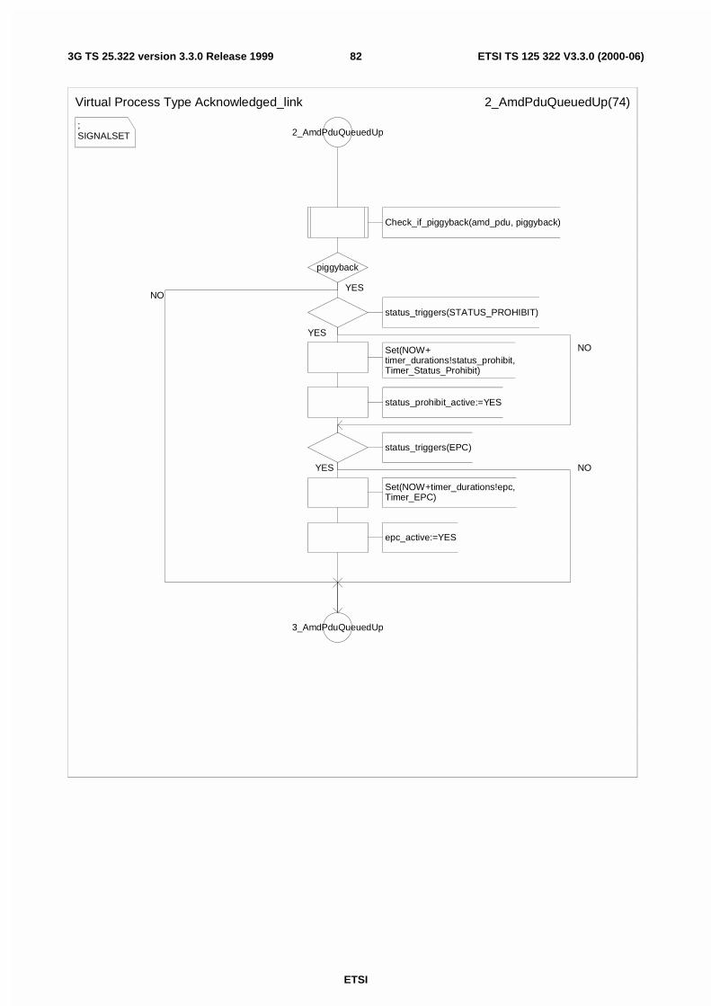
ETSI
ETSI TS 125 322 V3.3.0 (2000-06)823G TS 25.322 version 3.3.0 Release 1999
;SIGNALSET
Virtual Process Type Acknowledged_link 2_AmdPduQueuedUp(74)
2_AmdPduQueuedUp
Check_if_piggyback(amd_pdu, piggyback)
piggyback
status_triggers(STATUS_PROHIBIT)
Set(NOW+timer_durations!status_prohibit,Timer_Status_Prohibit)
status_prohibit_active:=YES
status_triggers(EPC)
Set(NOW+timer_durations!epc,Timer_EPC)
epc_active:=YES
3_AmdPduQueuedUp
YES
YES
YES NO
NO
NO
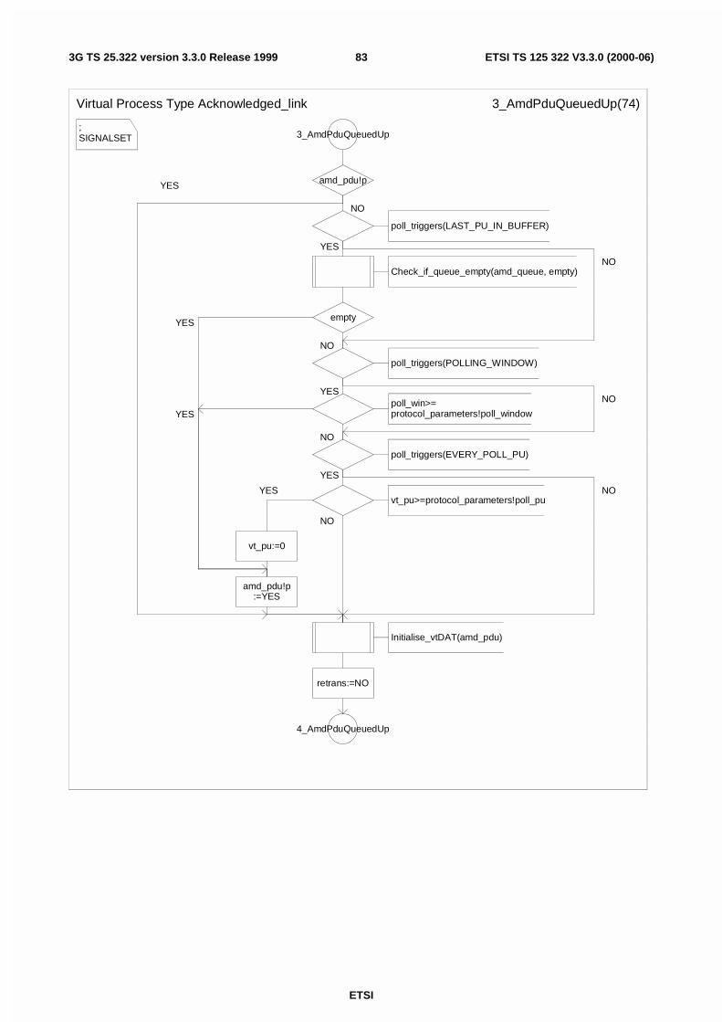
ETSI
ETSI TS 125 322 V3.3.0 (2000-06)833G TS 25.322 version 3.3.0 Release 1999
;SIGNALSET
Virtual Process Type Acknowledged_link 3_AmdPduQueuedUp(74)
3_AmdPduQueuedUp
amd_pdu!p
poll_triggers(LAST_PU_IN_BUFFER)
Check_if_queue_empty(amd_queue, empty)
empty
poll_triggers(POLLING_WINDOW)
poll_win>=protocol_parameters!poll_window
poll_triggers(EVERY_POLL_PU)
vt_pu>=protocol_parameters!poll_pu
vt_pu:=0
amd_pdu!p:=YES
Initialise_vtDAT(amd_pdu)
retrans:=NO
4_AmdPduQueuedUp
NO
YES
NO
YES
NO
YES
YES
NO
NO
YES
NO
YES
NO
YES
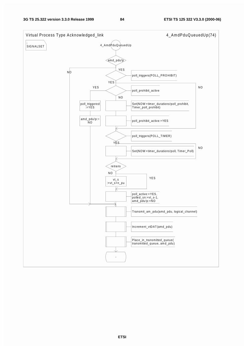
ETSI
ETSI TS 125 322 V3.3.0 (2000-06)843G TS 25.322 version 3.3.0 Release 1999
;S IG N A LS ET
V irtua l P rocess Type A cknow le dged_link 4_A m dP duQ ueuedU p(74)
4_A mdP du Q ueued Up
am d_ pdu !p
po ll_ triggers(P O L L_P RO HIBIT)
po ll_ pro hib it_ ac tive
po ll_ triggere d:=YES
am d_ pdu !p:=NO
Transm it_ am_ pdu(amd_ pdu , log ical_cha nne l)
Inc rem ent_v tD AT (am d_pdu)
P lace_in_ tra nsmitted_queue(transm itted_q ueu e, am d_ pdu )
-
S et(NO W +tim er_ durations!po ll_ pro hib it,T im er_poll_ pro hibit)
po ll_ pro hib it_ ac tive:=YES
po ll_ triggers(P O L L_TIM ER )
S et(NO W +tim er_ durations!po ll, T im er_P o ll)
re tra ns
vt_ s:=vt_s+n_pu
po ll_ active:= YES ,po lle d_sn:=vt_s-1, am d_ pdu !p:=NO
YE S
YE S
YE S
NO
YE S
NO
YE S
NO
NO
NO
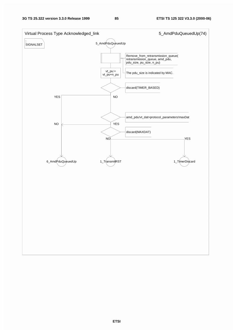
ETSI
ETSI TS 125 322 V3.3.0 (2000-06)853G TS 25.322 version 3.3.0 Release 1999
;SIGNALSET
Virtual Process Type Acknowledged_link 5_AmdPduQueuedUp(74)
5_AmdPduQueuedUp
Remove_from_retransmission_queue(retransmission_queue, amd_pdu, pdu_size, pu_size, n_pu)
The pdu_size is indicated by MAC.vt_pu:=vt_pu+n_pu
discard(TIMER_BASED)
amd_pdu!vt_dat>protocol_parameters!maxDat
discard(MAXDAT)
1_TransmitRST 1_TimerDiscard6_AmdPduQueuedUp
NO
YES
NO YES
NO
YES
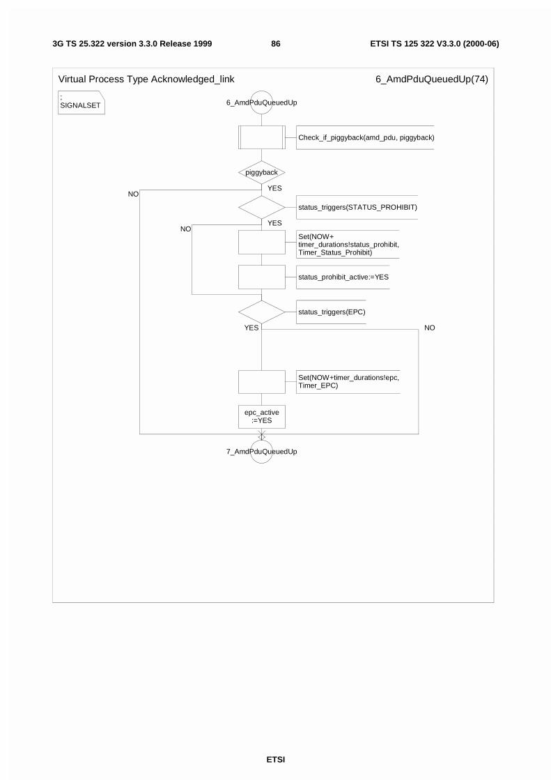
ETSI
ETSI TS 125 322 V3.3.0 (2000-06)863G TS 25.322 version 3.3.0 Release 1999
;SIGNALSET
Virtual Process Type Acknowledged_link 6_AmdPduQueuedUp(74)
6_AmdPduQueuedUp
Check_if_piggyback(amd_pdu, piggyback)
piggyback
status_triggers(STATUS_PROHIBIT)
Set(NOW+timer_durations!status_prohibit,Timer_Status_Prohibit)
status_prohibit_active:=YES
status_triggers(EPC)
Set(NOW+timer_durations!epc,Timer_EPC)
epc_active:=YES
7_AmdPduQueuedUp
YES
YES
YES NO
NO
NO
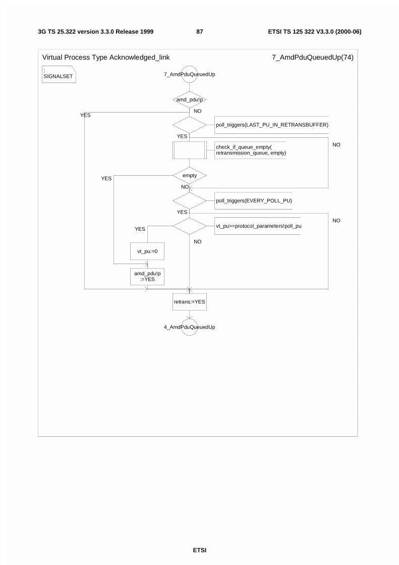
ETSI
ETSI TS 125 322 V3.3.0 (2000-06)873G TS 25.322 version 3.3.0 Release 1999
;SIGNALSET
Virtual Process Type Acknowledged_link 7_AmdPduQueuedUp(74)
7_AmdPduQueuedUp
amd_pdu!p
poll_triggers(LAST_PU_IN_RETRANSBUFFER)
check_if_queue_empty(retransmission_queue, empty)
empty
poll_triggers(EVERY_POLL_PU)
vt_pu>=protocol_parameters!poll_pu
vt_pu:=0
amd_pdu!p:=YES
retrans:=YES
4_AmdPduQueuedUp
NO
YES
NO
YES
YES
NO
NO
YES
NO
YES
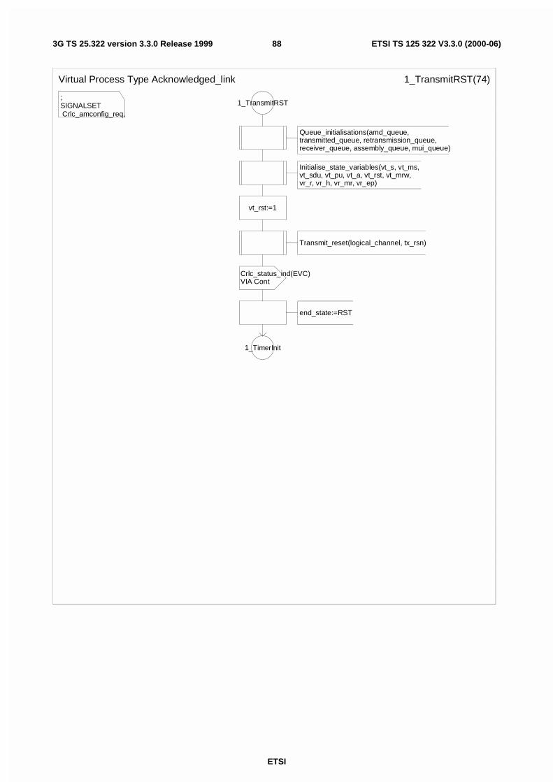
ETSI
ETSI TS 125 322 V3.3.0 (2000-06)883G TS 25.322 version 3.3.0 Release 1999
;SIGNALSET Crlc_amconfig_req,
Virtual Process Type Acknowledged_link 1_TransmitRST(74)
1_TransmitRST
Queue_initialisations(amd_queue, transmitted_queue, retransmission_queue, receiver_queue, assembly_queue, mui_queue)
Initialise_state_variables(vt_s, vt_ms, vt_sdu, vt_pu, vt_a, vt_rst, vt_mrw, vr_r, vr_h, vr_mr, vr_ep)
vt_rst:=1
Transmit_reset(logical_channel, tx_rsn)
Crlc_status_ind(EVC)VIA Cont
end_state:=RST
1_TimerInit
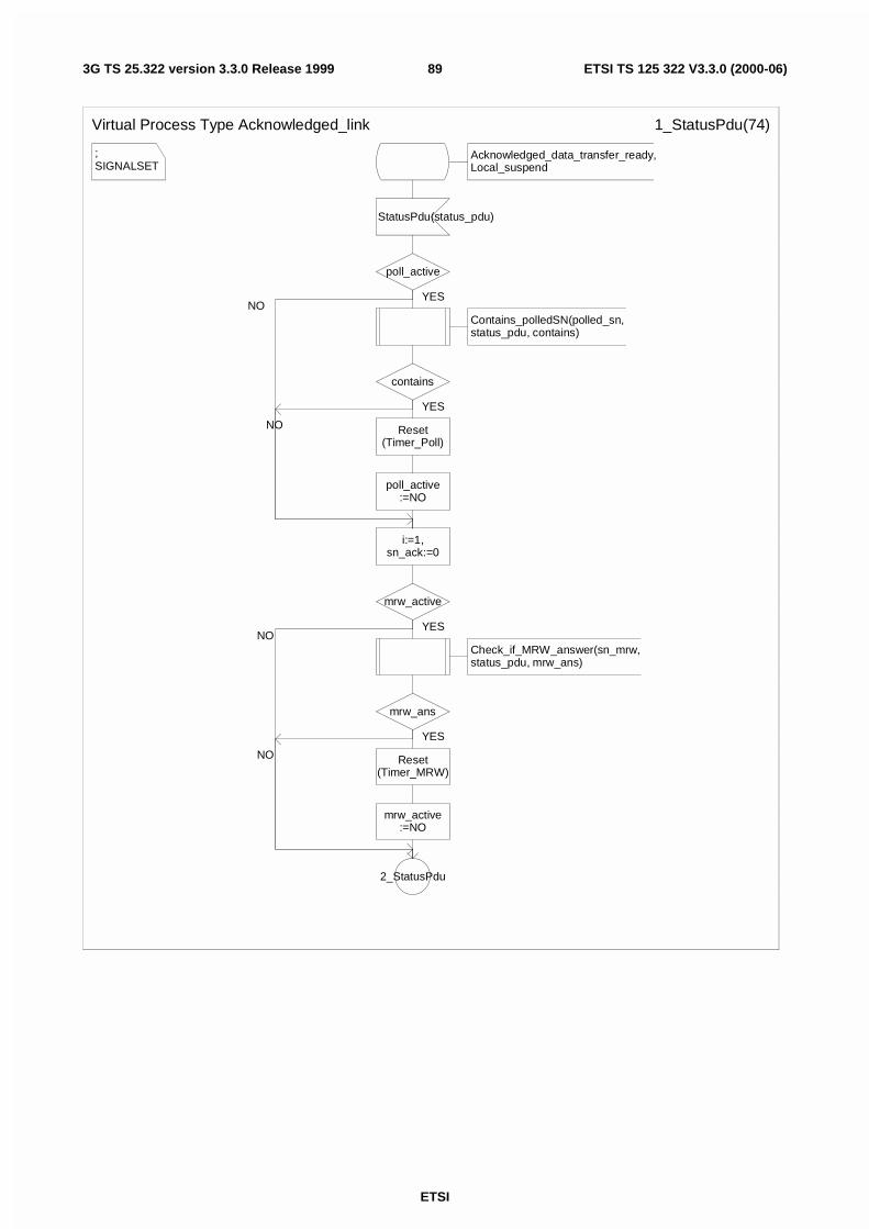
ETSI
ETSI TS 125 322 V3.3.0 (2000-06)893G TS 25.322 version 3.3.0 Release 1999
;SIGNALSET
Virtual Process Type Acknowledged_link 1_StatusPdu(74)
Acknowledged_data_transfer_ready,Local_suspend
StatusPdu(status_pdu)
poll_active
Contains_polledSN(polled_sn, status_pdu, contains)
contains
Reset(Timer_Poll)
poll_active:=NO
i:=1,sn_ack:=0
mrw_active
Check_if_MRW_answer(sn_mrw,status_pdu, mrw_ans)
mrw_ans
Reset(Timer_MRW)
mrw_active:=NO
2_StatusPdu
YES
YES
YES
YES
NO
NO
NO
NO
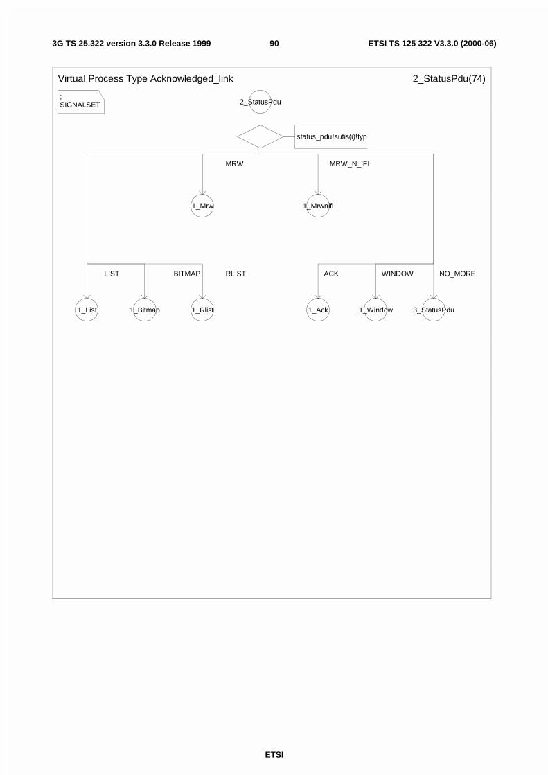
ETSI
ETSI TS 125 322 V3.3.0 (2000-06)903G TS 25.322 version 3.3.0 Release 1999
;SIGNALSET
Virtual Process Type Acknowledged_link 2_StatusPdu(74)
2_StatusPdu
status_pdu!sufis(i)!typ
1_Mrw 1_Mrwnifl
1_List 1_Bitmap 1_Rlist 1_Ack 1_Window 3_StatusPdu
MRW MRW_N_IFL
LIST BITMAP RLIST ACK WINDOW NO_MORE
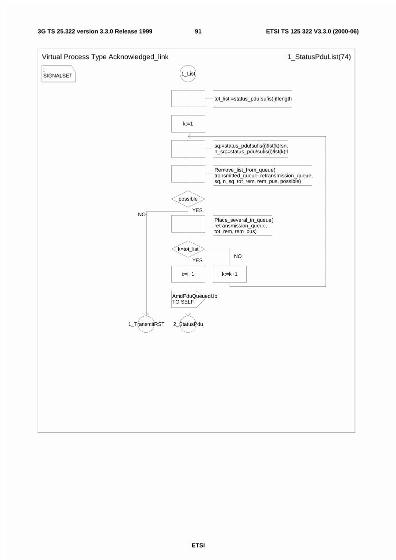
ETSI
ETSI TS 125 322 V3.3.0 (2000-06)913G TS 25.322 version 3.3.0 Release 1999
;SIGNALSET
Virtual Process Type Acknowledged_link 1_StatusPduList(74)
1_List
tot_list:=status_pdu!sufis(i)!length
k:=1
sq:=status_pdu!sufis(i)!lst(k)!sn,n_sq:=status_pdu!sufis(i)!lst(k)!l
Remove_list_from_queue(transmitted_queue, retransmission_queue,sq, n_sq, tot_rem, rem_pus, possible)
possible
Place_several_in_queue(retransmission_queue,tot_rem, rem_pus)
k=tot_list
i:=i+1
AmdPduQueuedUpTO SELF
2_StatusPdu
k:=k+1
1_TransmitRST
YES
YESNO
NO
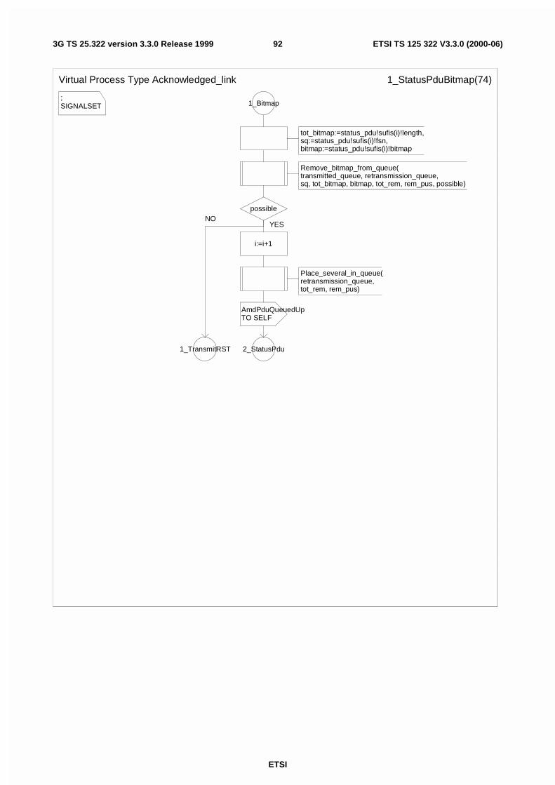
ETSI
ETSI TS 125 322 V3.3.0 (2000-06)923G TS 25.322 version 3.3.0 Release 1999
;SIGNALSET
Virtual Process Type Acknowledged_link 1_StatusPduBitmap(74)
1_Bitmap
tot_bitmap:=status_pdu!sufis(i)!length,sq:=status_pdu!sufis(i)!fsn,bitmap:=status_pdu!sufis(i)!bitmap
Remove_bitmap_from_queue(transmitted_queue, retransmission_queue,sq, tot_bitmap, bitmap, tot_rem, rem_pus, possible)
possible
i:=i+1
Place_several_in_queue(retransmission_queue,tot_rem, rem_pus)
AmdPduQueuedUpTO SELF
2_StatusPdu1_TransmitRST
YESNO

ETSI
ETSI TS 125 322 V3.3.0 (2000-06)933G TS 25.322 version 3.3.0 Release 1999
;SIGNALSET
Virtual Process Type Acknowledged_link 1_StatusPduRlist(74)
1_Rlist
tot_bitmap:=status_pdu!sufis(i)!length,sq:=status_pdu!sufis(i)!fsn,codewords:=status_pdu!sufis(i)!cw
Remove_rlist_from_queue(transmitted_queue, retransmission_queue,sq, tot_rlist, codewords, tot_rem, rem_pus, possible)
possible
i:=i+1
Place_several_in_queue(retransmission_queue,tot_rem, rem_pus)
AmdPduQueuedUpTO SELF
2_StatusPdu1_TransmitRST
YES
NO
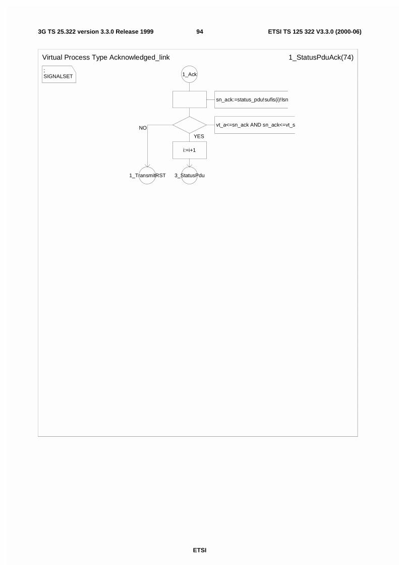
ETSI
ETSI TS 125 322 V3.3.0 (2000-06)943G TS 25.322 version 3.3.0 Release 1999
;SIGNALSET
Virtual Process Type Acknowledged_link 1_StatusPduAck(74)
1_Ack
sn_ack:=status_pdu!sufis(i)!lsn
vt_a<=sn_ack AND sn_ack<=vt_s
i:=i+1
3_StatusPdu1_TransmitRST
YES
NO
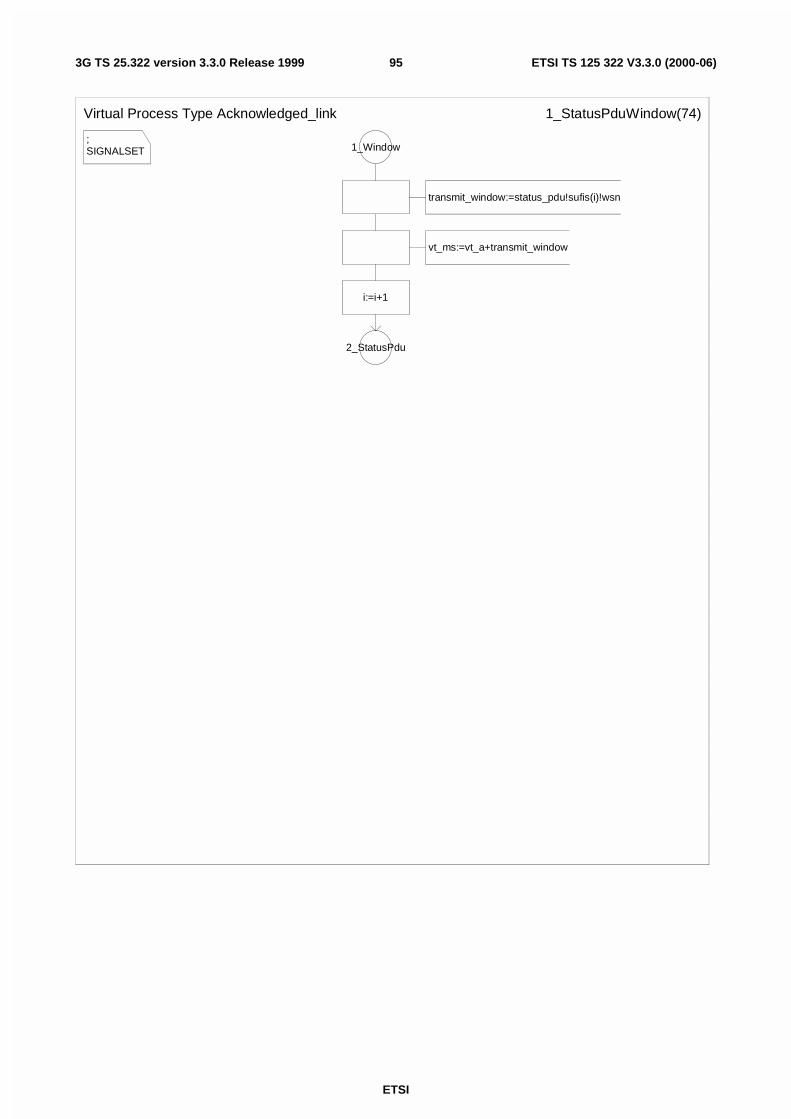
ETSI
ETSI TS 125 322 V3.3.0 (2000-06)953G TS 25.322 version 3.3.0 Release 1999
;SIGNALSET
Virtual Process Type Acknowledged_link 1_StatusPduWindow(74)
1_Window
transmit_window:=status_pdu!sufis(i)!wsn
vt_ms:=vt_a+transmit_window
i:=i+1
2_StatusPdu
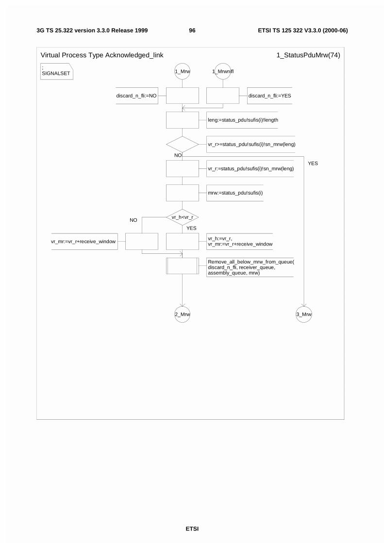
ETSI
ETSI TS 125 322 V3.3.0 (2000-06)963G TS 25.322 version 3.3.0 Release 1999
;SIGNALSET
Virtual Process Type Acknowledged_link 1_StatusPduMrw(74)
1_Mrw
discard_n_fli:=NO
leng:=status_pdu!sufis(i)!length
vr_r>=status_pdu!sufis(i)!sn_mrw(leng)
vr_r:=status_pdu!sufis(i)!sn_mrw(leng)
mrw:=status_pdu!sufis(i)
vr_h<vr_r
vr_mr:=vr_r+receive_window
Remove_all_below_mrw_from_queue(discard_n_fli, receiver_queue, assembly_queue, mrw)
2_Mrw
vr_h:=vr_r,vr_mr:=vr_r+receive_window
3_Mrw
1_Mrwnifl
discard_n_fli:=YES
NO
NO
YES
YES
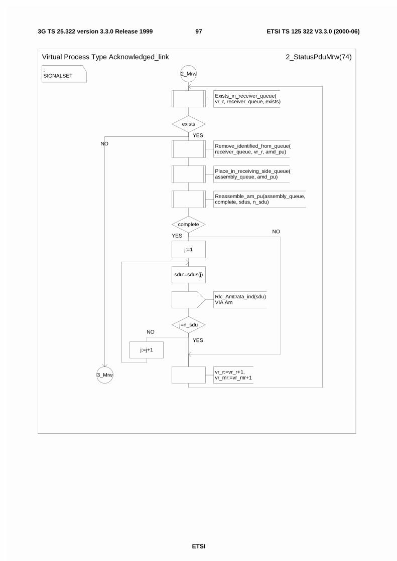
ETSI
ETSI TS 125 322 V3.3.0 (2000-06)973G TS 25.322 version 3.3.0 Release 1999
;SIGNALSET
Virtual Process Type Acknowledged_link 2_StatusPduMrw(74)
2_Mrw
Exists_in_receiver_queue(vr_r, receiver_queue, exists)
exists
Remove_identified_from_queue(receiver_queue, vr_r, amd_pu)
Place_in_receiving_side_queue(assembly_queue, amd_pu)
Reassemble_am_pu(assembly_queue, complete, sdus, n_sdu)
complete
j:=1
sdu:=sdus(j)
Rlc_AmData_ind(sdu)VIA Am
j=n_sdu
j:=j+1
vr_r:=vr_r+1,vr_mr:=vr_mr+13_Mrw
YES
YES
NO
YES
NO
NO
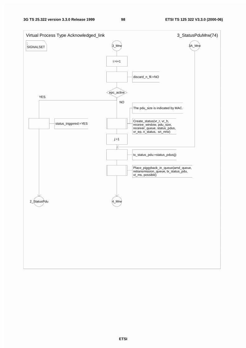
ETSI
ETSI TS 125 322 V3.3.0 (2000-06)983G TS 25.322 version 3.3.0 Release 1999
;SIGNALSET
Virtual Process Type Acknowledged_link 3_StatusPduMrw(74)
3_Mrw
i:=i+1
discard_n_fli:=NO
epc_active
status_triggered:=YES
2_StatusPdu
The pdu_size is indicated by MAC.
Create_status(vr_r, vr_h, receive_window, pdu_size, receiver_queue, status_pdus, vr_ep, n_status, sn_mrw)
j:=1
tx_status_pdu:=status_pdus(j)
Place_piggyback_in_queue(amd_queue, retransmission_queue, tx_status_pdu,vt_ms, possible)
4_Mrw
3A_Mrw
YES
NO
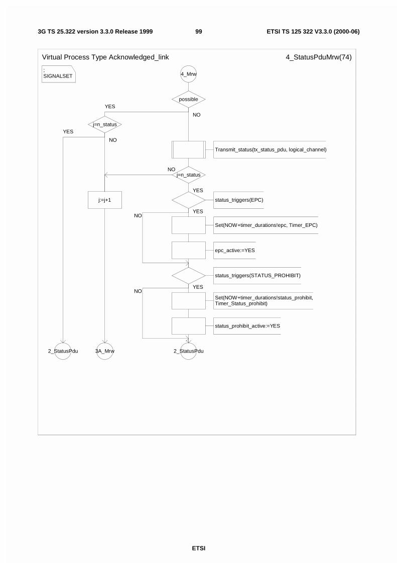
ETSI
ETSI TS 125 322 V3.3.0 (2000-06)993G TS 25.322 version 3.3.0 Release 1999
;SIGNALSET
Virtual Process Type Acknowledged_link 4_StatusPduMrw(74)
4_Mrw
possible
j=n_status
j:=j+1
3A_Mrw2_StatusPdu
Transmit_status(tx_status_pdu, logical_channel)
j=n_status
status_triggers(EPC)
Set(NOW+timer_durations!epc, Timer_EPC)
epc_active:=YES
status_triggers(STATUS_PROHIBIT)
Set(NOW+timer_durations!status_prohibit,Timer_Status_prohibit)
status_prohibit_active:=YES
2_StatusPdu
YES
NO
YES
NO
NO
YES
YES
YESNO
NO
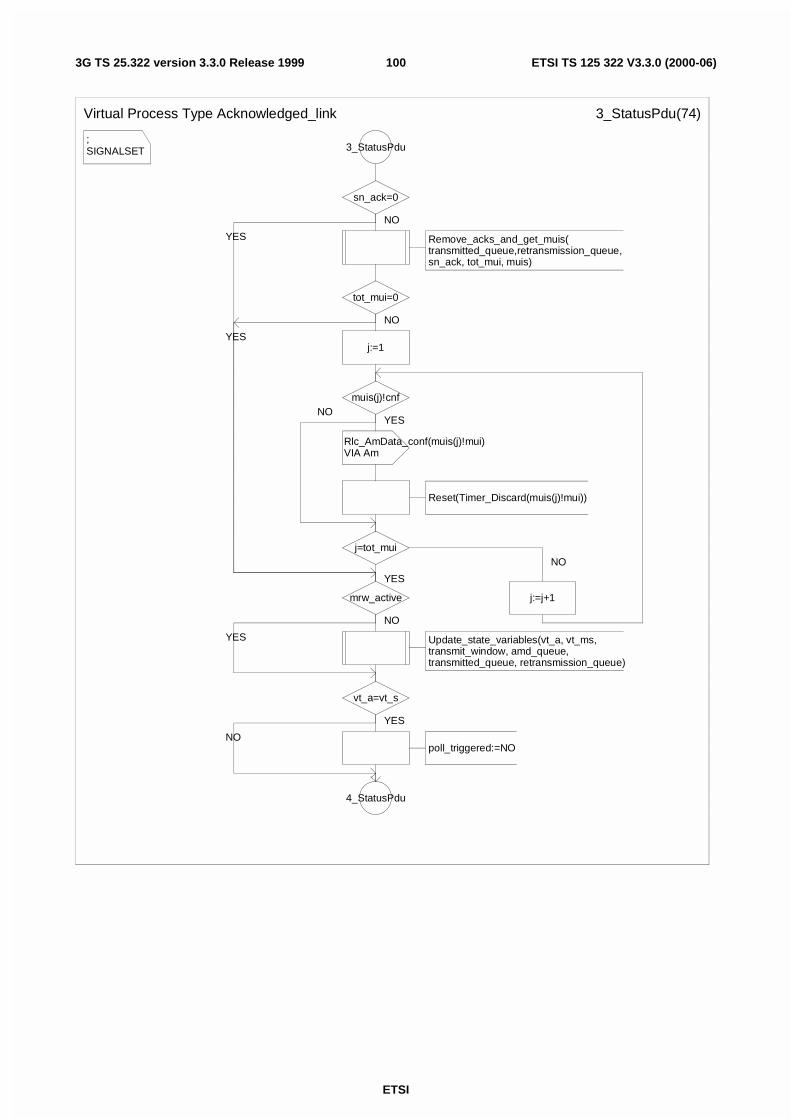
ETSI
ETSI TS 125 322 V3.3.0 (2000-06)1003G TS 25.322 version 3.3.0 Release 1999
;SIGNALSET
Virtual Process Type Acknowledged_link 3_StatusPdu(74)
3_StatusPdu
sn_ack=0
Remove_acks_and_get_muis(transmitted_queue,retransmission_queue, sn_ack, tot_mui, muis)
tot_mui=0
j:=1
muis(j)!cnf
Rlc_AmData_conf(muis(j)!mui)VIA Am
Reset(Timer_Discard(muis(j)!mui))
j=tot_mui
mrw_active
Update_state_variables(vt_a, vt_ms, transmit_window, amd_queue, transmitted_queue, retransmission_queue)
vt_a=vt_s
poll_triggered:=NO
4_StatusPdu
j:=j+1
NO
NO
YES
YES
NO
YES
NO
YES
NO
NO
YES
YES
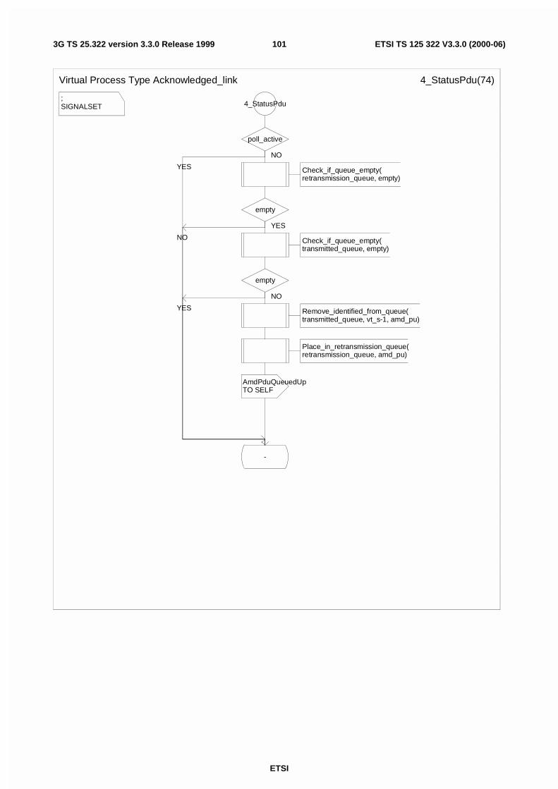
ETSI
ETSI TS 125 322 V3.3.0 (2000-06)1013G TS 25.322 version 3.3.0 Release 1999
;SIGNALSET
Virtual Process Type Acknowledged_link 4_StatusPdu(74)
4_StatusPdu
poll_active
Check_if_queue_empty(retransmission_queue, empty)
empty
Check_if_queue_empty(transmitted_queue, empty)
empty
Remove_identified_from_queue(transmitted_queue, vt_s-1, amd_pu)
Place_in_retransmission_queue(retransmission_queue, amd_pu)
AmdPduQueuedUpTO SELF
-
NO
YES
NO
YES
NO
YES
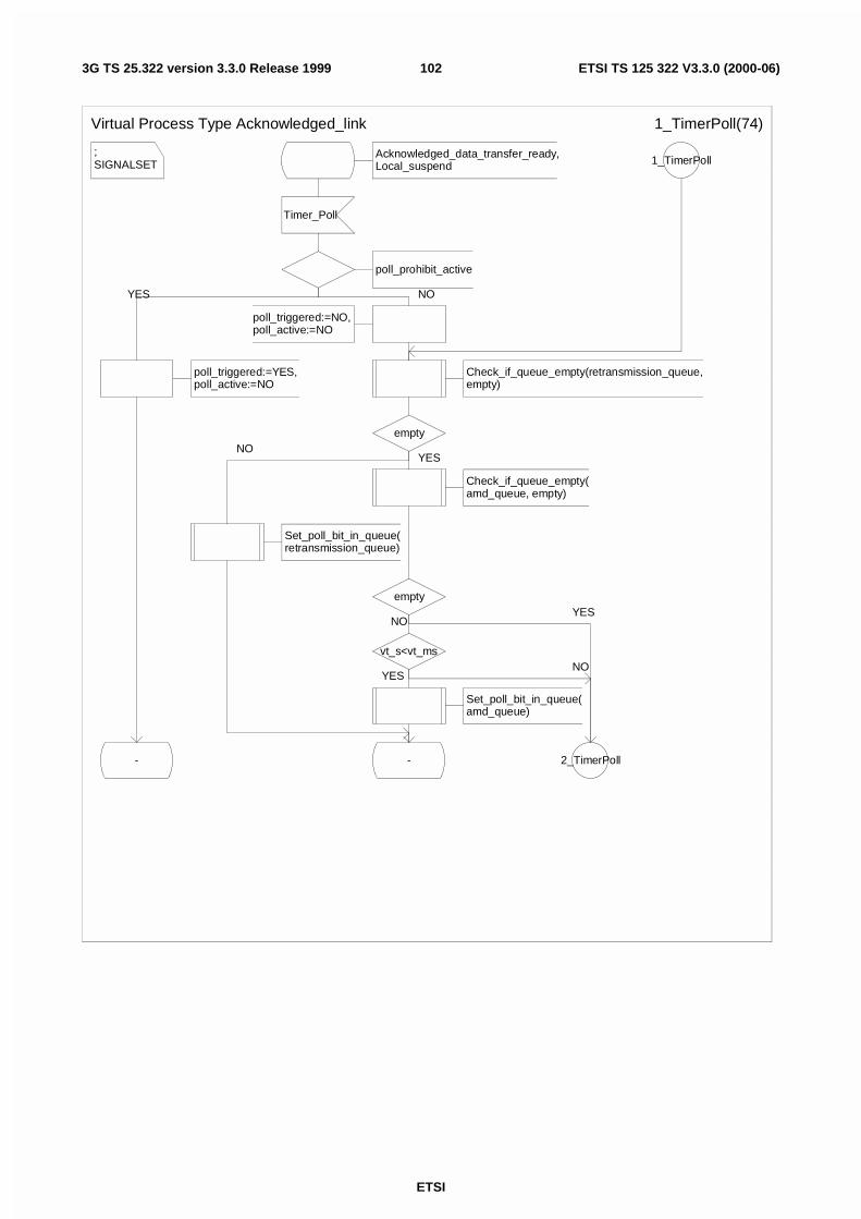
ETSI
ETSI TS 125 322 V3.3.0 (2000-06)1023G TS 25.322 version 3.3.0 Release 1999
;SIGNALSET
Virtual Process Type Acknowledged_link 1_TimerPoll(74)
Acknowledged_data_transfer_ready,Local_suspend
Timer_Poll
poll_prohibit_active
poll_triggered:=NO,poll_active:=NO
Check_if_queue_empty(retransmission_queue, empty)
empty
Check_if_queue_empty(amd_queue, empty)
empty
vt_s<vt_ms
Set_poll_bit_in_queue(amd_queue)
- 2_TimerPoll
Set_poll_bit_in_queue(retransmission_queue)
poll_triggered:=YES,poll_active:=NO
-
1_TimerPoll
NO
YES
NO
YESNO
YES
NO
YES
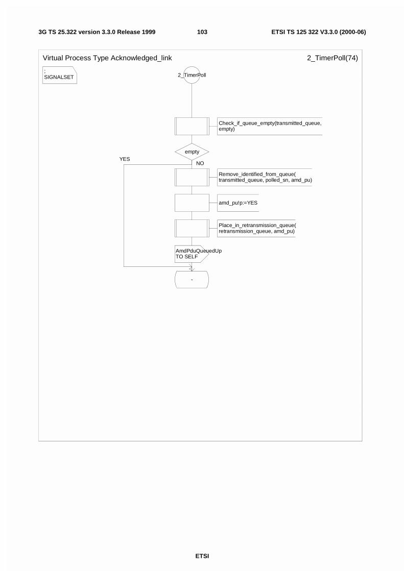
ETSI
ETSI TS 125 322 V3.3.0 (2000-06)1033G TS 25.322 version 3.3.0 Release 1999
;SIGNALSET
Virtual Process Type Acknowledged_link 2_TimerPoll(74)
2_TimerPoll
Check_if_queue_empty(transmitted_queue, empty)
empty
Remove_identified_from_queue(transmitted_queue, polled_sn, amd_pu)
amd_pu!p:=YES
Place_in_retransmission_queue(retransmission_queue, amd_pu)
AmdPduQueuedUpTO SELF
-
NOYES
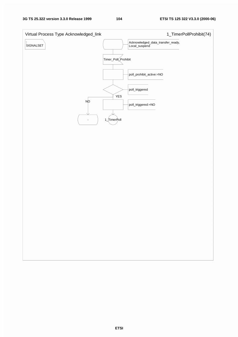
ETSI
ETSI TS 125 322 V3.3.0 (2000-06)1043G TS 25.322 version 3.3.0 Release 1999
;SIGNALSET
Virtual Process Type Acknowledged_link 1_TimerPollProhibit(74)
Acknowledged_data_transfer_ready,Local_suspend
Timer_Poll_Prohibit
poll_prohibit_active:=NO
poll_triggered
poll_triggered:=NO
1_TimerPoll-
YES
NO
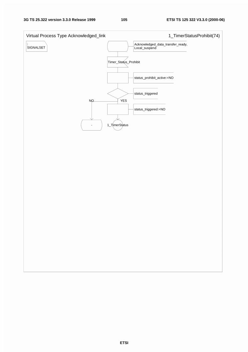
ETSI
ETSI TS 125 322 V3.3.0 (2000-06)1053G TS 25.322 version 3.3.0 Release 1999
;SIGNALSET
Virtual Process Type Acknowledged_link 1_TimerStatusProhibit(74)
Acknowledged_data_transfer_ready,Local_suspend
Timer_Status_Prohibit
status_prohibit_active:=NO
status_triggered
status_triggered:=NO
1_TimerStatus-
YESNO
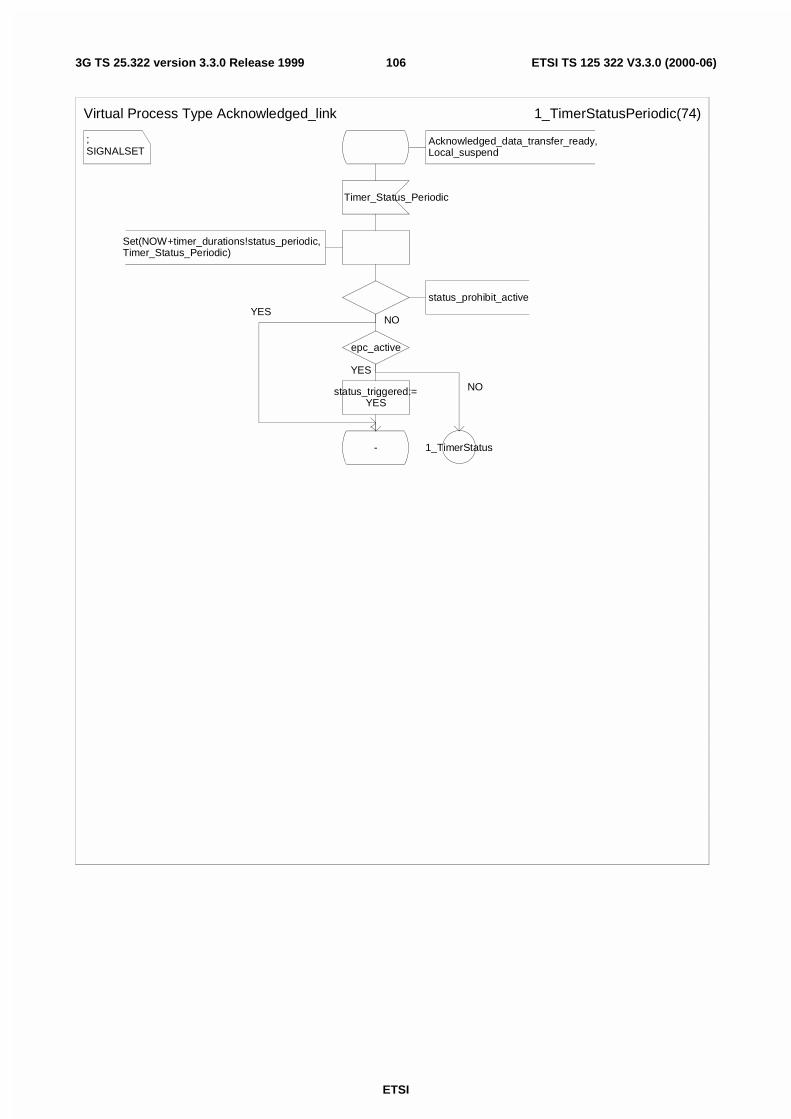
ETSI
ETSI TS 125 322 V3.3.0 (2000-06)1063G TS 25.322 version 3.3.0 Release 1999
;SIGNALSET
Virtual Process Type Acknowledged_link 1_TimerStatusPeriodic(74)
Acknowledged_data_transfer_ready,Local_suspend
Timer_Status_Periodic
Set(NOW+timer_durations!status_periodic,Timer_Status_Periodic)
status_prohibit_active
epc_active
status_triggered:=YES
- 1_TimerStatus
NO
YES
NO
YES
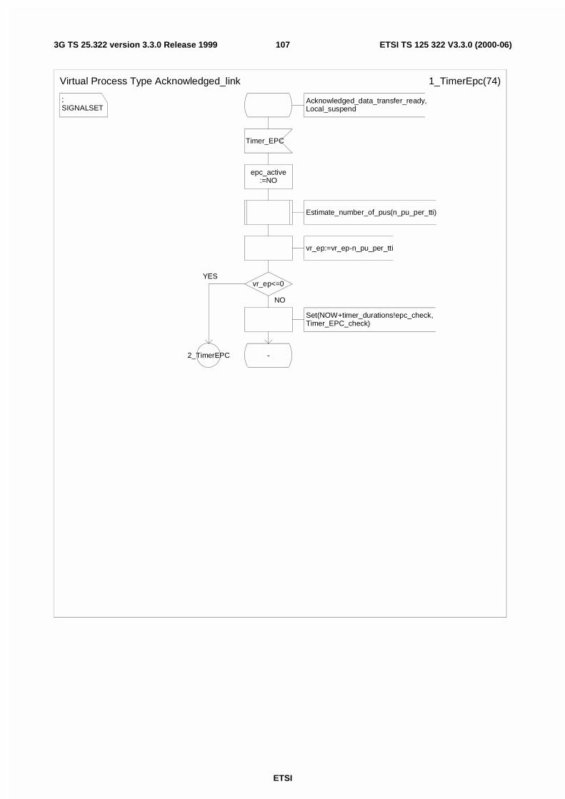
ETSI
ETSI TS 125 322 V3.3.0 (2000-06)1073G TS 25.322 version 3.3.0 Release 1999
;SIGNALSET
Virtual Process Type Acknowledged_link 1_TimerEpc(74)
Acknowledged_data_transfer_ready,Local_suspend
Timer_EPC
epc_active:=NO
Estimate_number_of_pus(n_pu_per_tti)
vr_ep:=vr_ep-n_pu_per_tti
vr_ep<=0
Set(NOW+timer_durations!epc_check, Timer_EPC_check)
-2_TimerEPC
NO
YES
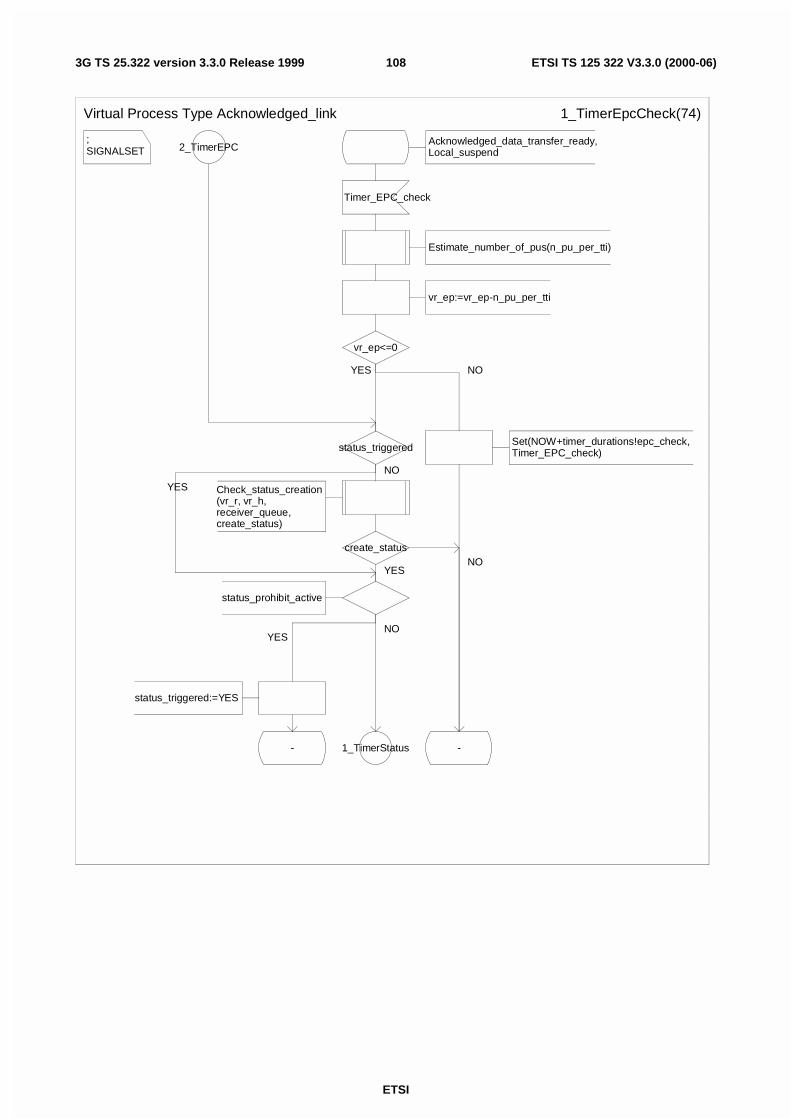
ETSI
ETSI TS 125 322 V3.3.0 (2000-06)1083G TS 25.322 version 3.3.0 Release 1999
;SIGNALSET
Virtual Process Type Acknowledged_link 1_TimerEpcCheck(74)
2_TimerEPC
status_triggered
Check_status_creation(vr_r, vr_h, receiver_queue,create_status)
create_status
status_prohibit_active
status_triggered:=YES
- 1_TimerStatus -
Acknowledged_data_transfer_ready,Local_suspend
Timer_EPC_check
Estimate_number_of_pus(n_pu_per_tti)
vr_ep:=vr_ep-n_pu_per_tti
vr_ep<=0
Set(NOW+timer_durations!epc_check, Timer_EPC_check)
NO
YES
YESNO
NO
YES
YES NO
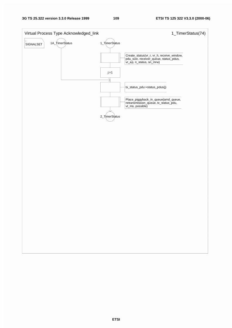
ETSI
ETSI TS 125 322 V3.3.0 (2000-06)1093G TS 25.322 version 3.3.0 Release 1999
;SIGNALSET
Virtual Process Type Acknowledged_link 1_TimerStatus(74)
1A_TimerStatus
tx_status_pdu:=status_pdus(j)
Place_piggyback_in_queue(amd_queue, retransmission_queue, tx_status_pdu, vt_ms, possible)
2_TimerStatus
1_TimerStatus
Create_status(vr_r, vr_h, receive_window, pdu_size, receiver_queue, status_pdus, vr_ep, n_status, sn_mrw)
j:=1
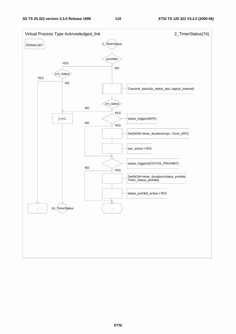
ETSI
ETSI TS 125 322 V3.3.0 (2000-06)1103G TS 25.322 version 3.3.0 Release 1999
;SIGNALSET
Virtual Process Type Acknowledged_link 2_TimerStatus(74)
2_TimerStatus
possible
j=n_status
j:=j+1
1A_TimerStatus-
Transmit_status(tx_status_pdu, logical_channel)
j=n_status
status_triggers(EPC)
Set(NOW+timer_durations!epc, Timer_EPC)
epc_active:=YES
status_triggers(STATUS_PROHIBIT)
Set(NOW+timer_durations!status_prohibit,Timer_Status_prohibit)
status_prohibit_active:=YES
-
YES
NO
YES
NO
NO
YES
YES
YESNO
NO
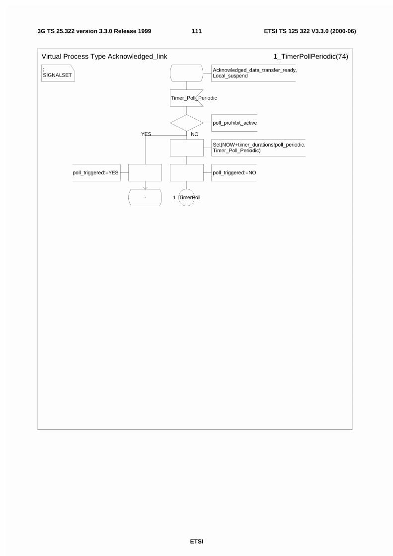
ETSI
ETSI TS 125 322 V3.3.0 (2000-06)1113G TS 25.322 version 3.3.0 Release 1999
;SIGNALSET
Virtual Process Type Acknowledged_link 1_TimerPollPeriodic(74)
Acknowledged_data_transfer_ready,Local_suspend
Timer_Poll_Periodic
poll_prohibit_active
Set(NOW+timer_durations!poll_periodic,Timer_Poll_Periodic)
poll_triggered:=NO
1_TimerPoll
poll_triggered:=YES
-
NOYES
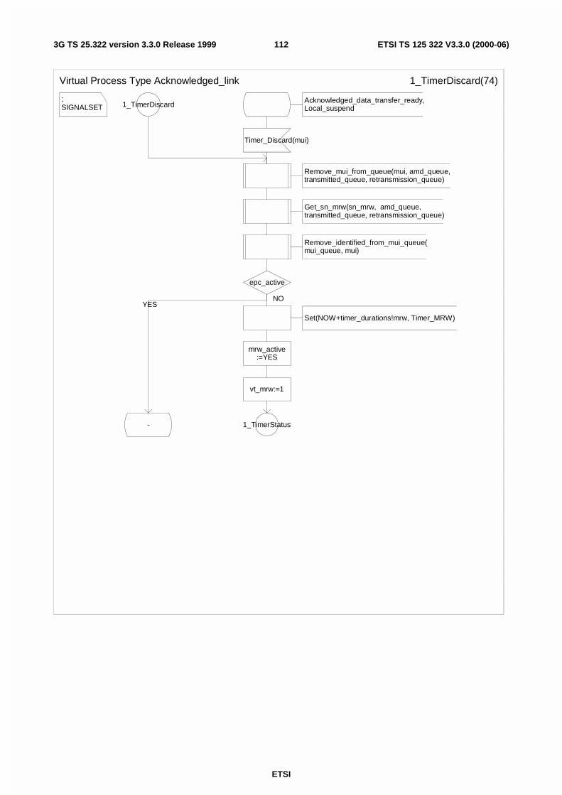
ETSI
ETSI TS 125 322 V3.3.0 (2000-06)1123G TS 25.322 version 3.3.0 Release 1999
;SIGNALSET
Virtual Process Type Acknowledged_link 1_TimerDiscard(74)
1_TimerDiscardAcknowledged_data_transfer_ready,Local_suspend
Timer_Discard(mui)
Remove_mui_from_queue(mui, amd_queue,transmitted_queue, retransmission_queue)
Get_sn_mrw(sn_mrw, amd_queue, transmitted_queue, retransmission_queue)
Remove_identified_from_mui_queue(mui_queue, mui)
epc_active
Set(NOW+timer_durations!mrw, Timer_MRW)
mrw_active:=YES
vt_mrw:=1
- 1_TimerStatus
NOYES
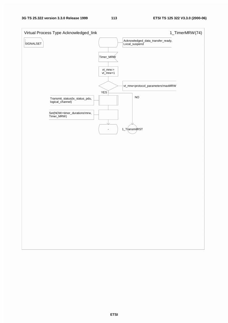
ETSI
ETSI TS 125 322 V3.3.0 (2000-06)1133G TS 25.322 version 3.3.0 Release 1999
;SIGNALSET
Virtual Process Type Acknowledged_link 1_TimerMRW(74)
Acknowledged_data_transfer_ready,Local_suspend
Timer_MRW
vt_mrw:=vt_mrw+1
vt_mrw<protocol_parameters!maxMRW
Transmit_status(tx_status_pdu, logical_channel)
Set(NOW+timer_durations!mrw, Timer_MRW)
- 1_TransmitRST
YES
NO
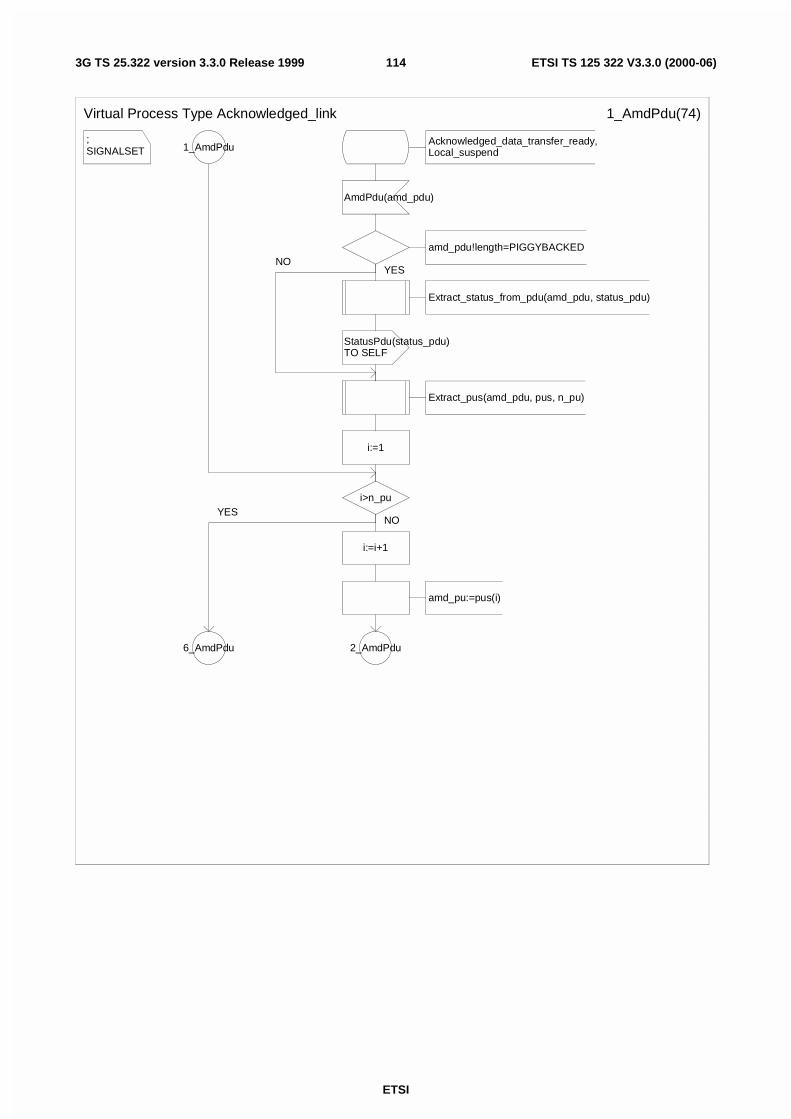
ETSI
ETSI TS 125 322 V3.3.0 (2000-06)1143G TS 25.322 version 3.3.0 Release 1999
;SIGNALSET
Virtual Process Type Acknowledged_link 1_AmdPdu(74)
1_AmdPdu
i>n_pu
i:=i+1
amd_pu:=pus(i)
2_AmdPdu6_AmdPdu
Acknowledged_data_transfer_ready,Local_suspend
AmdPdu(amd_pdu)
amd_pdu!length=PIGGYBACKED
Extract_status_from_pdu(amd_pdu, status_pdu)
StatusPdu(status_pdu)TO SELF
Extract_pus(amd_pdu, pus, n_pu)
i:=1
NOYES
YESNO
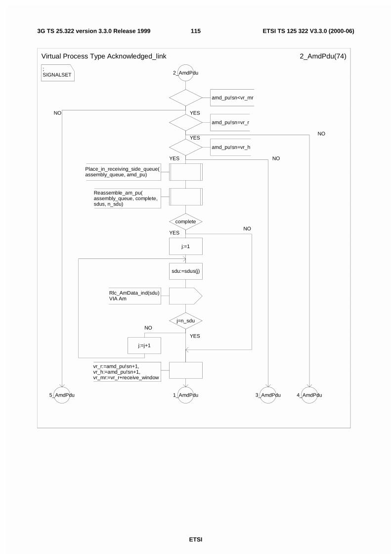
ETSI
ETSI TS 125 322 V3.3.0 (2000-06)1153G TS 25.322 version 3.3.0 Release 1999
;SIGNALSET
Virtual Process Type Acknowledged_link 2_AmdPdu(74)
2_AmdPdu
amd_pu!sn<vr_mr
amd_pu!sn=vr_r
amd_pu!sn=vr_h
Place_in_receiving_side_queue(assembly_queue, amd_pu)
Reassemble_am_pu(assembly_queue, complete, sdus, n_sdu)
complete
j:=1
sdu:=sdus(j)
Rlc_AmData_ind(sdu)VIA Am
j=n_sdu
j:=j+1
vr_r:=amd_pu!sn+1,vr_h:=amd_pu!sn+1,vr_mr:=vr_r+receive_window
1_AmdPdu 3_AmdPdu 4_AmdPdu5_AmdPdu
YES
YES
YES
YES
NO
YES
NO
NO
NO
NO
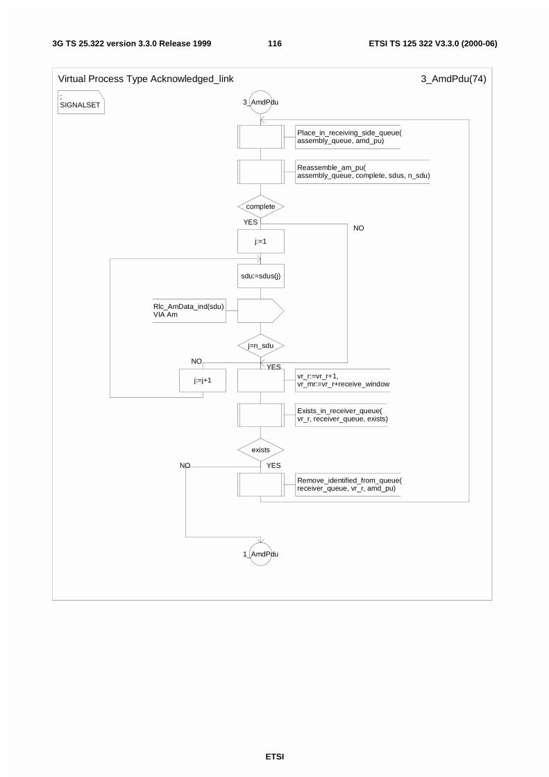
ETSI
ETSI TS 125 322 V3.3.0 (2000-06)1163G TS 25.322 version 3.3.0 Release 1999
;SIGNALSET
Virtual Process Type Acknowledged_link 3_AmdPdu(74)
3_AmdPdu
Place_in_receiving_side_queue(assembly_queue, amd_pu)
Reassemble_am_pu(assembly_queue, complete, sdus, n_sdu)
complete
j:=1
sdu:=sdus(j)
Rlc_AmData_ind(sdu)VIA Am
j=n_sdu
j:=j+1 vr_r:=vr_r+1,vr_mr:=vr_r+receive_window
Exists_in_receiver_queue(vr_r, receiver_queue, exists)
exists
Remove_identified_from_queue(receiver_queue, vr_r, amd_pu)
1_AmdPdu
YES
NOYES
YESNO
NO
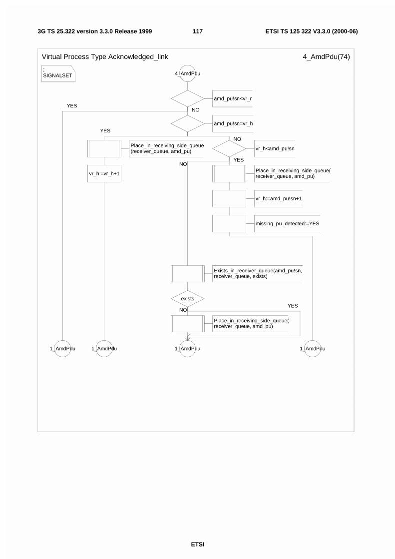
ETSI
ETSI TS 125 322 V3.3.0 (2000-06)1173G TS 25.322 version 3.3.0 Release 1999
;SIGNALSET
Virtual Process Type Acknowledged_link 4_AmdPdu(74)
4_AmdPdu
amd_pu!sn<vr_r
amd_pu!sn=vr_h
Place_in_receiving_side_queue(receiver_queue, amd_pu)
vr_h:=vr_h+1
1_AmdPdu
vr_h<amd_pu!sn
Place_in_receiving_side_queue(receiver_queue, amd_pu)
vr_h:=amd_pu!sn+1
missing_pu_detected:=YES
1_AmdPdu
Exists_in_receiver_queue(amd_pu!sn, receiver_queue, exists)
exists
Place_in_receiving_side_queue(receiver_queue, amd_pu)
1_AmdPdu1_AmdPdu
NO
YES
NO
YESNO
NOYES
YES
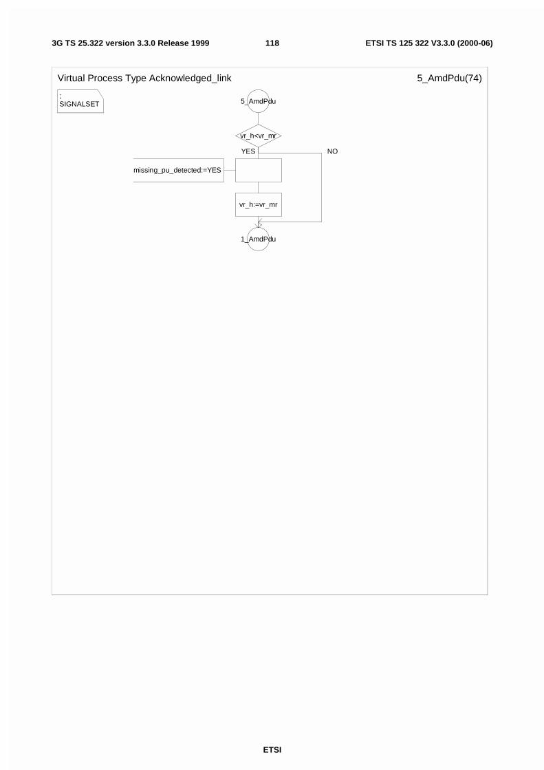
ETSI
ETSI TS 125 322 V3.3.0 (2000-06)1183G TS 25.322 version 3.3.0 Release 1999
;SIGNALSET
Virtual Process Type Acknowledged_link 5_AmdPdu(74)
5_AmdPdu
vr_h<vr_mr
missing_pu_detected:=YES
vr_h:=vr_mr
1_AmdPdu
YES NO
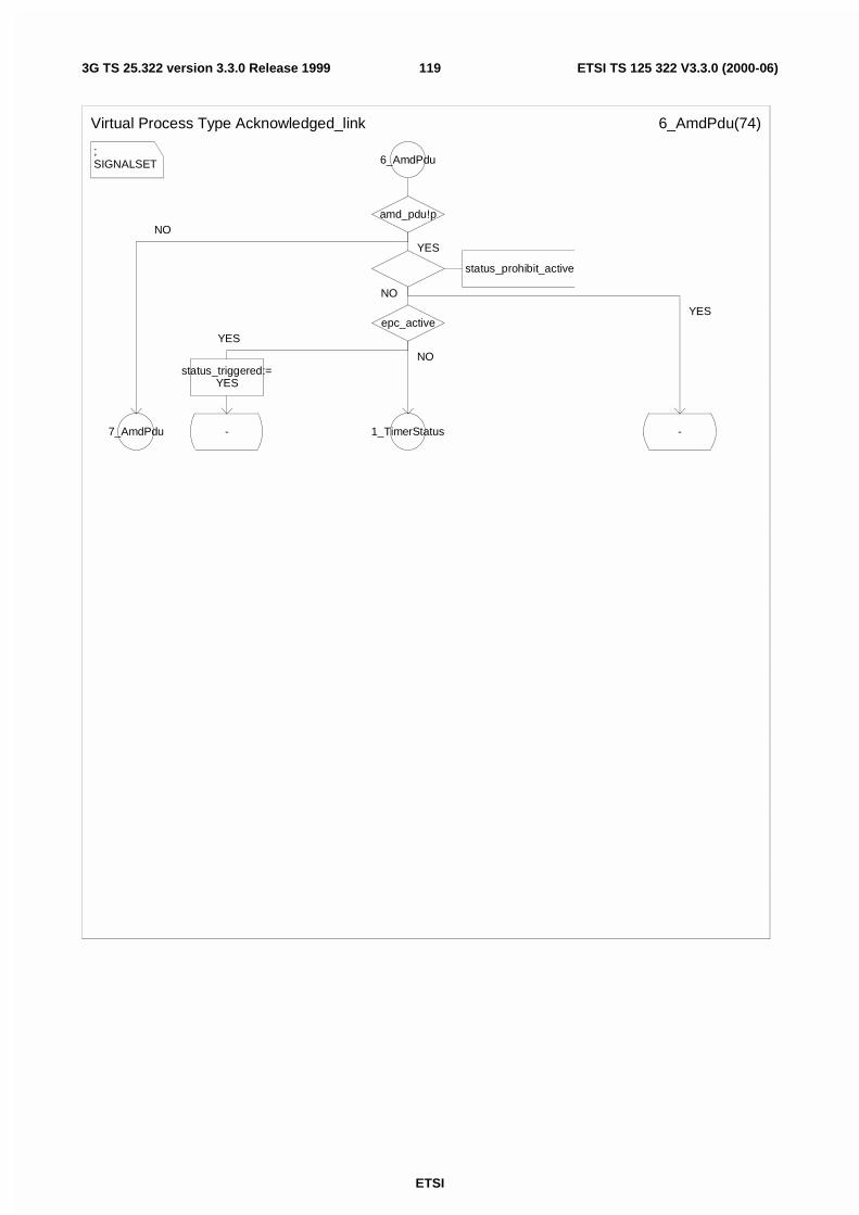
ETSI
ETSI TS 125 322 V3.3.0 (2000-06)1193G TS 25.322 version 3.3.0 Release 1999
;SIGNALSET
Virtual Process Type Acknowledged_link 6_AmdPdu(74)
6_AmdPdu
amd_pdu!p
status_prohibit_active
epc_active
status_triggered:=YES
- 1_TimerStatus -7_AmdPdu
YES
NO
YES
NO
YES
NO
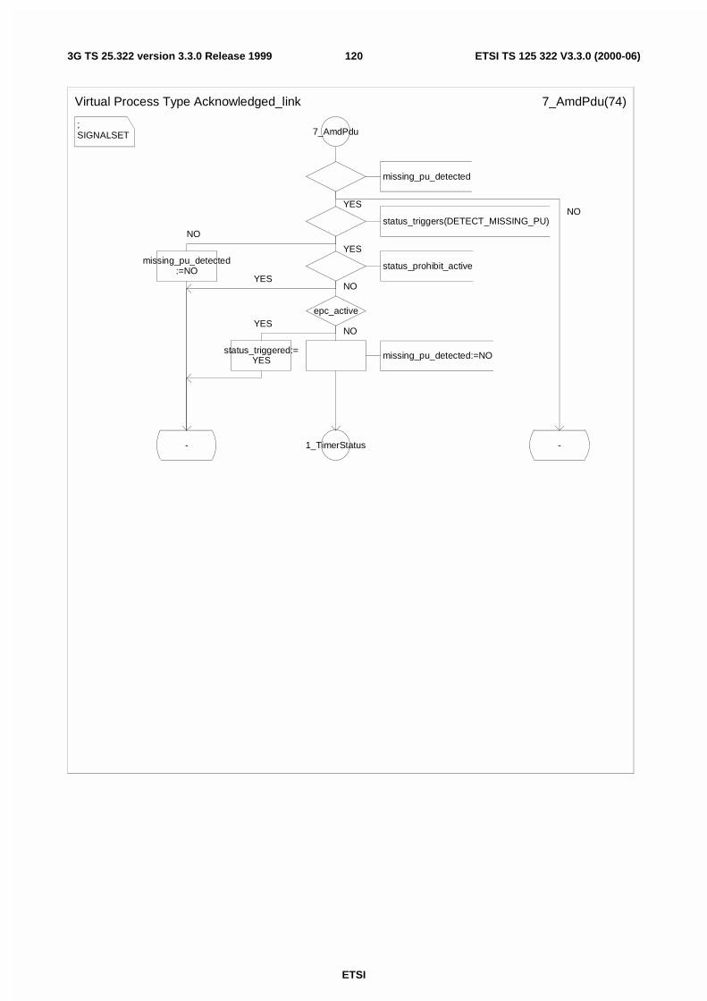
ETSI
ETSI TS 125 322 V3.3.0 (2000-06)1203G TS 25.322 version 3.3.0 Release 1999
;SIGNALSET
Virtual Process Type Acknowledged_link 7_AmdPdu(74)
7_AmdPdu
missing_pu_detected
status_triggers(DETECT_MISSING_PU)
missing_pu_detected:=NO
-
status_prohibit_active
epc_active
status_triggered:=YES missing_pu_detected:=NO
1_TimerStatus -
YES
NO
YES
NO
YESNO
YES
NO
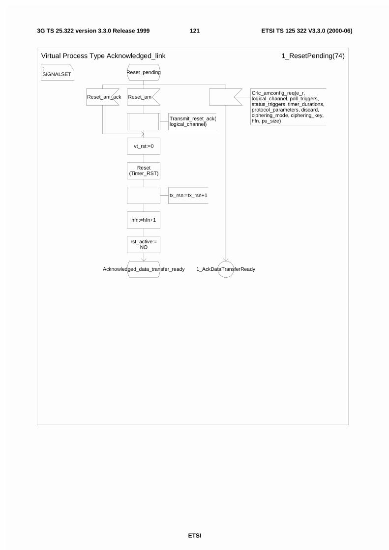
ETSI
ETSI TS 125 322 V3.3.0 (2000-06)1213G TS 25.322 version 3.3.0 Release 1999
;SIGNALSET
Virtual Process Type Acknowledged_link 1_ResetPending(74)
Reset_pending
Reset_am_ack
vt_rst:=0
Reset(Timer_RST)
tx_rsn:=tx_rsn+1
hfn:=hfn+1
rst_active:=NO
Acknowledged_data_transfer_ready
Reset_am
Transmit_reset_ack(logical_channel)
Crlc_amconfig_req(e_r, logical_channel, poll_triggers, status_triggers, timer_durations, protocol_parameters, discard, ciphering_mode, ciphering_key, hfn, pu_size)
1_AckDataTransferReady
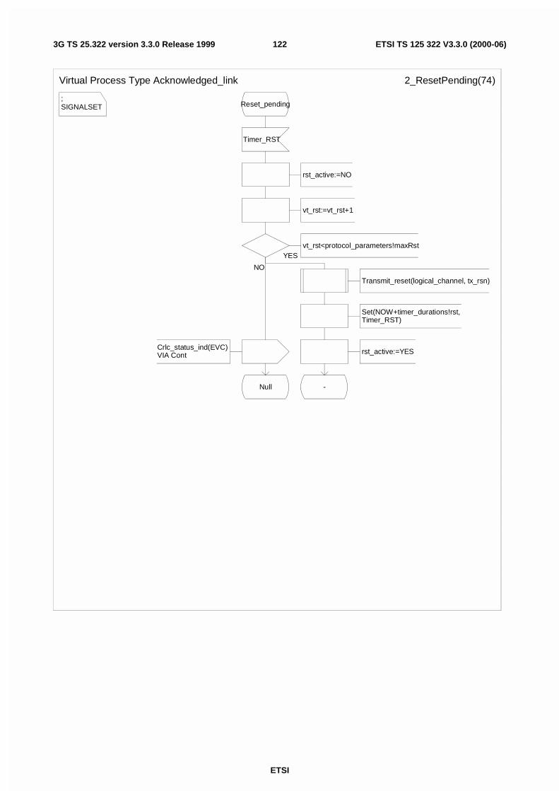
ETSI
ETSI TS 125 322 V3.3.0 (2000-06)1223G TS 25.322 version 3.3.0 Release 1999
;SIGNALSET
Virtual Process Type Acknowledged_link 2_ResetPending(74)
Reset_pending
Timer_RST
rst_active:=NO
vt_rst:=vt_rst+1
vt_rst<protocol_parameters!maxRst
Transmit_reset(logical_channel, tx_rsn)
Set(NOW+timer_durations!rst,Timer_RST)
rst_active:=YES
-
Crlc_status_ind(EVC)VIA Cont
Null
YES
NO
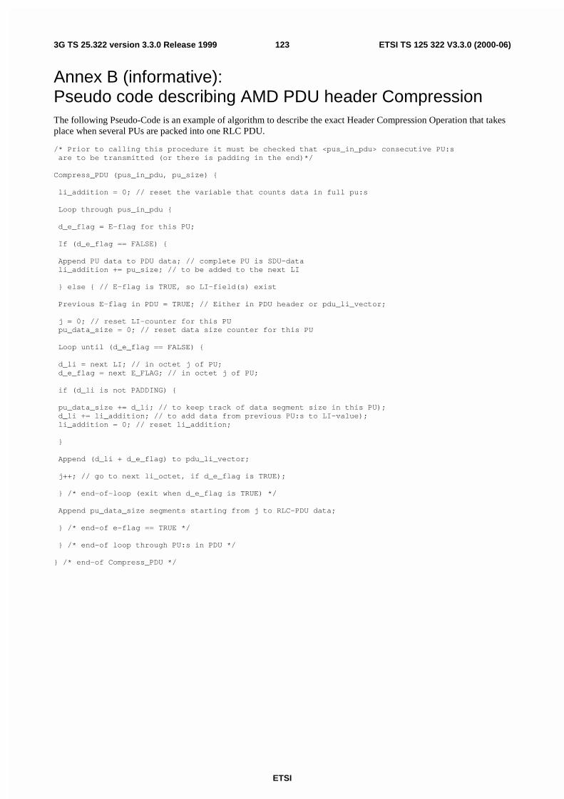
ETSI
ETSI TS 125 322 V3.3.0 (2000-06)1233G TS 25.322 version 3.3.0 Release 1999
Annex B (informative):Pseudo code describing AMD PDU header CompressionThe following Pseudo-Code is an example of algorithm to describe the exact Header Compression Operation that takesplace when several PUs are packed into one RLC PDU.
/* Prior to calling this procedure it must be checked that <pus_in_pdu> consecutive PU:s are to be transmitted (or there is padding in the end)*/
Compress_PDU (pus_in_pdu, pu_size) {
li_addition = 0; // reset the variable that counts data in full pu:s
Loop through pus_in_pdu {
d_e_flag = E-flag for this PU;
If (d_e_flag == FALSE) {
Append PU data to PDU data; // complete PU is SDU-data li_addition += pu_size; // to be added to the next LI
} else { // E-flag is TRUE, so LI-field(s) exist
Previous E-flag in PDU = TRUE; // Either in PDU header or pdu_li_vector;
j = 0; // reset LI-counter for this PU pu_data_size = 0; // reset data size counter for this PU
Loop until (d_e_flag == FALSE) {
d_li = next LI; // in octet j of PU; d_e_flag = next E_FLAG; // in octet j of PU;
if (d_li is not PADDING) {
pu_data_size += d_li; // to keep track of data segment size in this PU); d_li += li_addition; // to add data from previous PU:s to LI-value); li_addition = 0; // reset li_addition;
}
Append (d_li + d_e_flag) to pdu_li_vector;
j++; // go to next li_octet, if d_e_flag is TRUE);
} /* end-of-loop (exit when d_e_flag is TRUE) */
Append pu_data_size segments starting from j to RLC-PDU data;
} /* end-of e-flag == TRUE */
} /* end-of loop through PU:s in PDU */
} /* end-of Compress_PDU */
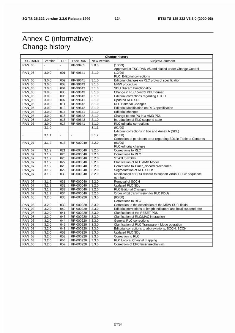
ETSI
ETSI TS 125 322 V3.3.0 (2000-06)1243G TS 25.322 version 3.3.0 Release 1999
Annex C (informative):Change history
Change historyTSG-RAN# Version CR Tdoc RAN New Version Subject/CommentRAN_05 - - RP-99465 3.0.0 (10/99)
Approved at TSG-RAN #5 and placed under Change ControlRAN_06 3.0.0 001 RP-99641 3.1.0 (12/99)
RLC: Editorial correctionsRAN_06 3.0.0 002 RP-99641 3.1.0 Editorial changes on RLC protocol specificationRAN_06 3.0.0 003 RP-99643 3.1.0 MRW procedureRAN_06 3.0.0 004 RP-99643 3.1.0 SDU Discard FunctionalityRAN_06 3.0.0 005 RP-99643 3.1.0 Change in RLC control PDU formatRAN_06 3.0.0 006 RP-99642 3.1.0 Editorial corrections regarding CTCHRAN_06 3.0.0 007 RP-99641 3.1.0 Updated RLC SDLRAN_06 3.0.0 011 RP-99642 3.1.0 RLC Editorial ChangesRAN_06 3.0.0 013 RP-99642 3.1.0 Editorial Modification on RLC specificationRAN_06 3.0.0 014 RP-99641 3.1.0 Editorial changesRAN_06 3.0.0 015 RP-99642 3.1.0 Change to one PU in a AMD PDURAN_06 3.0.0 016 RP-99643 3.1.0 Introduction of RLC suspend stateRAN_06 3.0.0 017 RP-99641 3.1.0 RLC editorial corrections- 3.1.0 - - 3.1.1 (01/00)
Editorial corrections in title and Annex A (SDL)- 3.1.1 - - 3.1.2 (01/00)
Correction of persistent error regarding SDL in Table of ContentsRAN_07 3.1.2 018 RP-000040 3.2.0 (03/00)
RLC editorial changesRAN_07 3.1.2 021 RP-000040 3.2.0 Corrections to RLCRAN_07 3.1.2 025 RP-000040 3.2.0 Corrections to RLCRAN_07 3.1.2 026 RP-000040 3.2.0 STATUS PDUsRAN_07 3.1.2 027 RP-000040 3.2.0 Clarification of RLC AMD ModelRAN_07 3.1.2 028 RP-000040 3.2.0 Corrections to Timer_discard proceduresRAN_07 3.1.2 029 RP-000040 3.2.0 Segmentation of RLC SDUsRAN_07 3.1.2 030 RP-000040 3.2.0 Modification of SDU discard to support virtual PDCP sequence
numbersRAN_07 3.1.2 031 RP-000040 3.2.0 Removal of SCCHRAN_07 3.1.2 032 RP-000040 3.2.0 Updated RLC SDLRAN_07 3.1.2 033 RP-000040 3.2.0 RLC Editorial ChangesRAN_07 3.1.2 034 RP-000040 3.2.0 Order of bit transmission for RLC PDUsRAN_08 3.2.0 038 RP-000220 3.3.0 (06/00)
Corrections to RLCRAN_08 3.2.0 039 RP-000220 3.3.0 Correction to the description of the MRW SUFI fieldsRAN_08 3.2.0 040 RP-000220 3.3.0 Editorial corrections to length indicators and local suspend rateRAN_08 3.2.0 041 RP-000220 3.3.0 Clarification of the RESET PDURAN_08 3.2.0 043 RP-000220 3.3.0 Clarification of RLC/MAC interactionRAN_08 3.2.0 044 RP-000220 3.3.0 General RLC correctionsRAN_08 3.2.0 045 RP-000220 3.3.0 Clarification of RLC Transparent Mode operationRAN_08 3.2.0 048 RP-000220 3.3.0 Editorial corrections to abbreviations, SCCH, BCCHRAN_08 3.2.0 052 RP-000220 3.3.0 Updated RLC SDLRAN_08 3.2.0 053 RP-000220 3.3.0 Correction to RLCRAN_08 3.2.0 055 RP-000220 3.3.0 RLC Logical Channel mappingRAN_08 3.2.0 057 RP-000220 3.3.0 Correction of EPC timer mechanism
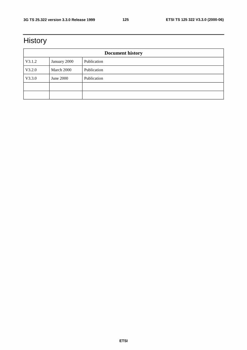
125
ETSI
ETSI TS 125 322 V3.3.0 (2000-06)3G TS 25.322 version 3.3.0 Release 1999
History
Document history
V3.1.2 January 2000 Publication
V3.2.0 March 2000 Publication
V3.3.0 June 2000 Publication