TS 123 682 - ETSI - Welcome to the World of Standards! · 4.5.13.2 Paging for extended idle mode...
83
ETSI TS 1 Digital cellular telecomm Universal Mobile Te Architecture enhancem packet data (3GPP TS 23.6 TECHNICAL SPECIFICATION 123 682 V13.4.0 (201 munications system (Phase elecommunications System ( LTE; ments to facilitate communic a networks and applications 682 version 13.4.0 Release 1 N 16-03) e 2+) (GSM); (UMTS); cations with 13)
Transcript of TS 123 682 - ETSI - Welcome to the World of Standards! · 4.5.13.2 Paging for extended idle mode...
ETSI TS 1
Digital cellular telecommUniversal Mobile Tel
Architecture enhancempacket data
(3GPP TS 23.6
TECHNICAL SPECIFICATION
123 682 V13.4.0 (2016
mmunications system (Phase elecommunications System (
LTE; ments to facilitate communicata networks and applications .682 version 13.4.0 Release 13
ION
16-03)
e 2+) (GSM); (UMTS);
ications with s 13)
ETSI
ETSI TS 123 682 V13.4.0 (2016-03)13GPP TS 23.682 version 13.4.0 Release 13
Reference RTS/TSGS-0223682vd40
Keywords LTE, GSM, UMTS
ETSI
650 Route des Lucioles F-06921 Sophia Antipolis Cedex - FRANCE
Tel.: +33 4 92 94 42 00 Fax: +33 4 93 65 47 16
Siret N° 348 623 562 00017 - NAF 742 C
Association à but non lucratif enregistrée à la Sous-Préfecture de Grasse (06) N° 7803/88
Important notice
The present document can be downloaded from: http://www.etsi.org/standards-search
The present document may be made available in electronic versions and/or in print. The content of any electronic and/or print versions of the present document shall not be modified without the prior written authorization of ETSI. In case of any
existing or perceived difference in contents between such versions and/or in print, the only prevailing document is the print of the Portable Document Format (PDF) version kept on a specific network drive within ETSI Secretariat.
Users of the present document should be aware that the document may be subject to revision or change of status. Information on the current status of this and other ETSI documents is available at
http://portal.etsi.org/tb/status/status.asp
If you find errors in the present document, please send your comment to one of the following services: https://portal.etsi.org/People/CommiteeSupportStaff.aspx
Copyright Notification
No part may be reproduced or utilized in any form or by any means, electronic or mechanical, including photocopying and microfilm except as authorized by written permission of ETSI.
The content of the PDF version shall not be modified without the written authorization of ETSI. The copyright and the foregoing restriction extend to reproduction in all media.
© European Telecommunications Standards Institute 2016.
All rights reserved.
DECTTM, PLUGTESTSTM, UMTSTM and the ETSI logo are Trade Marks of ETSI registered for the benefit of its Members. 3GPPTM and LTE™ are Trade Marks of ETSI registered for the benefit of its Members and
of the 3GPP Organizational Partners. GSM® and the GSM logo are Trade Marks registered and owned by the GSM Association.
ETSI
ETSI TS 123 682 V13.4.0 (2016-03)23GPP TS 23.682 version 13.4.0 Release 13
Intellectual Property Rights IPRs essential or potentially essential to the present document may have been declared to ETSI. The information pertaining to these essential IPRs, if any, is publicly available for ETSI members and non-members, and can be found in ETSI SR 000 314: "Intellectual Property Rights (IPRs); Essential, or potentially Essential, IPRs notified to ETSI in respect of ETSI standards", which is available from the ETSI Secretariat. Latest updates are available on the ETSI Web server (https://ipr.etsi.org/).
Pursuant to the ETSI IPR Policy, no investigation, including IPR searches, has been carried out by ETSI. No guarantee can be given as to the existence of other IPRs not referenced in ETSI SR 000 314 (or the updates on the ETSI Web server) which are, or may be, or may become, essential to the present document.
Foreword This Technical Specification (TS) has been produced by ETSI 3rd Generation Partnership Project (3GPP).
The present document may refer to technical specifications or reports using their 3GPP identities, UMTS identities or GSM identities. These should be interpreted as being references to the corresponding ETSI deliverables.
The cross reference between GSM, UMTS, 3GPP and ETSI identities can be found under http://webapp.etsi.org/key/queryform.asp.
Modal verbs terminology In the present document "shall", "shall not", "should", "should not", "may", "need not", "will", "will not", "can" and "cannot" are to be interpreted as described in clause 3.2 of the ETSI Drafting Rules (Verbal forms for the expression of provisions).
"must" and "must not" are NOT allowed in ETSI deliverables except when used in direct citation.
ETSI
ETSI TS 123 682 V13.4.0 (2016-03)33GPP TS 23.682 version 13.4.0 Release 13
Contents
Intellectual Property Rights ................................................................................................................................ 2
Foreword ............................................................................................................................................................. 2
Modal verbs terminology .................................................................................................................................... 2
Foreword ............................................................................................................................................................. 6
1 Scope ........................................................................................................................................................ 7
2 References ................................................................................................................................................ 7
3 Definitions and abbreviations ................................................................................................................... 8
3.1 Definitions .......................................................................................................................................................... 8
3.2 Abbreviations ..................................................................................................................................................... 8
4 Architecture Model and Concepts ............................................................................................................ 9
4.1 General Concept ................................................................................................................................................. 9
4.2 Architectural Reference Model .......................................................................................................................... 9
4.3 Reference points ............................................................................................................................................... 13
4.3.1 General ........................................................................................................................................................ 13
4.3.2 List of Reference Points .............................................................................................................................. 13
4.3.3 Reference Point Requirements .................................................................................................................... 14
4.3.3.1 Tsp Reference Point Requirements ....................................................................................................... 14
4.3.3.2 T4 Reference Point Requirements ......................................................................................................... 14
4.3.3.3 T5a/T5b/T5c Reference Point Requirements ........................................................................................ 14
4.3.3.4 S6m Reference Point Requirements ...................................................................................................... 15
4.3.3.5 S6n Reference Point Requirements ....................................................................................................... 15
4.3.3.6 T6a/T6b Reference Point Requirements ............................................................................................... 15
4.3.3.7 S6t Reference Point Requirements ........................................................................................................ 15
4.3.3.8 T6ai/T6bi Reference Point Requirements ............................................................................................. 15
4.3.3.9 T7 Reference Point Requirements ......................................................................................................... 16
4.3.3.10 Ns Reference Point Requirements ......................................................................................................... 16
4.4 Network Elements ............................................................................................................................................ 16
4.4.1 General ........................................................................................................................................................ 16
4.4.2 MTC-IWF ................................................................................................................................................... 16
4.4.3 HSS/HLR .................................................................................................................................................... 17
4.4.4 GGSN/P-GW .............................................................................................................................................. 18
4.4.5 SGSN/MME/MSC ...................................................................................................................................... 18
4.4.7 MTC AAA .................................................................................................................................................. 19
4.4.8 Service Capability Exposure Function ........................................................................................................ 19
4.4.9 Interworking SCEF ..................................................................................................................................... 20
4.4.10 RAN Congestion Awareness Function ....................................................................................................... 20
4.5 High Level Function ......................................................................................................................................... 21
4.5.1 Device Triggering Function ........................................................................................................................ 21
4.5.2 PS-only Service Provision .......................................................................................................................... 21
4.5.3 Core Network assisted RAN parameters tuning ......................................................................................... 21
4.5.4 UE Power Saving Mode ............................................................................................................................. 21
4.5.5 Group Message Delivery ............................................................................................................................ 23
4.5.6 Monitoring Events ...................................................................................................................................... 23
4.5.6.1 General .................................................................................................................................................. 23
4.5.6.2 Monitoring Events via HSS and MME/SGSN ...................................................................................... 23
4.5.6.3 Monitoring Events via PCRF ................................................................................................................ 24
4.5.6.4 Charging Principles ............................................................................................................................... 24
4.5.7 High latency communication ...................................................................................................................... 24
4.5.8 Support of informing about potential network issues ................................................................................. 25
4.5.9 Resource management of background data transfer ................................................................................... 25
4.5.10 E-UTRAN network resource optimizations based on communication patterns provided to the MME ...... 26
4.5.11 Support of setting up an AS session with required QoS ............................................................................. 26
4.5.12 Change the chargeable party at session set-up or during the session .......................................................... 26
ETSI
ETSI TS 123 682 V13.4.0 (2016-03)43GPP TS 23.682 version 13.4.0 Release 13
4.5.13 Extended idle mode DRX ........................................................................................................................... 26
4.5.13.1 General .................................................................................................................................................. 26
4.5.13.2 Paging for extended idle mode DRX in UTRAN .................................................................................. 27
4.5.13.3 Paging for extended idle mode DRX in E-UTRAN .............................................................................. 28
4.5.13.3.1 Hyper SFN, Paging Hyperframe and Paging Time Window length ................................................ 28
4.5.13.3.2 Loose Hyper SFN synchronization .................................................................................................. 28
4.5.13.3.3 MME paging and paging retransmission strategy ........................................................................... 28
4.6 Identifiers ......................................................................................................................................................... 29
4.6.1 General ........................................................................................................................................................ 29
4.6.2 External Identifier ....................................................................................................................................... 29
4.7 Addressing ........................................................................................................................................................ 29
4.8 Security Aspects ............................................................................................................................................... 29
4.8.1 Security Requirements ................................................................................................................................ 29
4.8.1.0 General .................................................................................................................................................. 29
4.8.1.1 Void....................................................................................................................................................... 29
4.8.1.2 Void....................................................................................................................................................... 29
5 Functional Description and Information Flow ....................................................................................... 30
5.1 Control and user plane ...................................................................................................................................... 30
5.1.1 Control Plane .............................................................................................................................................. 30
5.1.1.1 HSS – MTC-IWF .................................................................................................................................. 30
5.2 Device triggering procedures ........................................................................................................................... 31
5.2.1 Device triggering procedure over Tsp ........................................................................................................ 31
5.2.2 Trigger Delivery using T4 .......................................................................................................................... 33
5.2.3 Device triggering recall/replace procedures................................................................................................ 34
5.2.3.1 Device trigger recall/replace procedure over Tsp ................................................................................. 34
5.2.3.2 Replace procedure for trigger delivery using T4 ................................................................................... 35
5.2.3.3 Recall procedure for trigger delivery using T4 ..................................................................................... 37
5.3 Information Storage .......................................................................................................................................... 38
5.3.1 Trigger Information in SMS-SC (Triggering with T4) ............................................................................... 38
5.4 Security Procedures .......................................................................................................................................... 38
5.4.0 General ........................................................................................................................................................ 38
5.4.1 Void ............................................................................................................................................................ 38
5.4.2 Void ............................................................................................................................................................ 38
5.5 Group message delivery procedures ................................................................................................................. 39
5.5.1 Group message delivery using MBMS ....................................................................................................... 39
5.6 Monitoring Procedures ..................................................................................................................................... 41
5.6.1 Monitoring Event configuration and deletion via HSS ............................................................................... 41
5.6.1.1 Configuration Procedure ....................................................................................................................... 41
5.6.1.2 Common Parameters of the Configuration Procedure ........................................................................... 43
5.6.1.3 Specific Parameters for Monitoring Event: Loss of connectivity ......................................................... 44
5.6.1.4 Specific Parameters for Monitoring Event: UE reachability ................................................................. 44
5.6.1.5 Specific Parameters for Monitoring Event: Location Reporting ........................................................... 45
5.6.1.6 Specific Parameters for Monitoring Event: Change of IMSI-IMEI(SV) Association ........................... 46
5.6.1.7 Specific Parameters for Monitoring Event: Roaming Status ................................................................. 46
5.6.1.8 Specific Parameters for Monitoring Event: Communication failure ..................................................... 47
5.6.1.9 Specific Parameters for Monitoring Event: Availability after DDN Failure ......................................... 47
5.6.2 Monitoring Events configuration and deletion directly at the MME/SGSN ............................................... 47
5.6.2.1 Configuration Procedure ....................................................................................................................... 47
5.6.2.2 Common Parameters of the Configuration Procedure ........................................................................... 48
5.6.2.3 Specific Steps for Monitoring Event: Number of UEs present in a geographic area ............................ 48
5.6.3 Reporting of Monitoring Events from the HSS or the MME/SGSN .......................................................... 49
5.6.3.1 Reporting Procedure.............................................................................................................................. 49
5.6.3.2 Reporting Event: Loss of connectivity .................................................................................................. 50
5.6.3.3 Reporting Event: UE reachability ......................................................................................................... 50
5.6.3.4 Reporting Event: Location Reporting ................................................................................................... 50
5.6.3.5 Reporting Event: Change of IMSI-IMEI(SV) association .................................................................... 50
5.6.3.6 Reporting Event: Roaming Status ......................................................................................................... 51
5.6.3.7 Reporting Event: Communication failure ............................................................................................. 51
5.6.3.8 Reporting Event: Availability after DDN failure .................................................................................. 51
5.6.4 Monitoring events configuration and reporting via PCRF .......................................................................... 51
5.6.4.1 Request of monitoring event reporting .................................................................................................. 51
ETSI
ETSI TS 123 682 V13.4.0 (2016-03)53GPP TS 23.682 version 13.4.0 Release 13
5.6.4.2 Common Parameters of the request reporting procedure ...................................................................... 52
5.6.4.3 Specific Parameters for Monitoring Event: Location Reporting ........................................................... 52
5.6.4.4 Specific Parameters for Monitoring Event: Communication Failure .................................................... 52
5.6.5 Reporting of Monitoring Events from the PCRF ........................................................................................ 53
5.6.6 Monitoring Event configuration and deletion via HSS for roaming scenarios using an IWK-SCEF ......... 53
5.6.6.1 Configuration Procedure ....................................................................................................................... 53
5.6.6.2 Common Parameters of the Configuration Procedure ........................................................................... 56
5.6.6.3 Specific Parameters for Monitoring Event: Loss of connectivity ......................................................... 56
5.6.6.4 Specific Parameters for Monitoring Event: UE reachability ................................................................. 56
5.6.6.5 Specific Parameters for Monitoring Event: Location Reporting ........................................................... 56
5.6.6.6 Specific Parameters for Monitoring Event: Change of IMSI-IMEI(SV) Association ........................... 57
5.6.6.7 Specific Parameters for Monitoring Event: Roaming Status ................................................................. 57
5.6.6.8 Specific Parameters for Monitoring Event: Communication failure ..................................................... 57
5.6.6.9 Specific Parameters for Monitoring Event: Availability after DDN Failure ......................................... 58
5.6.7 Monitoring Events configuration and deletion directly at the MME/SGSN for roaming scenarios ........... 58
5.6.8 Reporting of Monitoring Events from the HSS or the MME/SGSN for roaming scenarios ....................... 58
5.6.8.1 Reporting Procedure.............................................................................................................................. 58
5.6.8.2 Reporting Event: Loss of connectivity .................................................................................................. 59
5.6.8.3 Reporting Event: UE reachability ......................................................................................................... 59
5.6.8.4 Reporting Event: Location Reporting ................................................................................................... 59
5.6.8.5 Reporting Event: Change of IMSI-IMEI(SV) association .................................................................... 59
5.6.8.6 Reporting Event: Roaming Status ......................................................................................................... 59
5.6.8.7 Reporting Event: Communication failure ............................................................................................. 59
5.6.8.8 Reporting Event: Availability after DDN failure .................................................................................. 60
5.7 High latency communications procedures ........................................................................................................ 60
5.7.1 Availability Notification after DDN Failure ............................................................................................... 60
5.7.1.1 General .................................................................................................................................................. 60
5.7.1.2 Event Configuration .............................................................................................................................. 60
5.7.1.3 Notification ........................................................................................................................................... 61
5.7.2 Notification using Monitoring Event "UE Reachability" ........................................................................... 62
5.8 Procedure for Informing about Potential Network Issues ................................................................................ 62
5.8.1 General ........................................................................................................................................................ 62
5.8.2 Request procedure for one-time or continuous reporting of network status ............................................... 63
5.8.3 Report procedure for continuous reporting of network status ..................................................................... 64
5.8.4 Removal procedure for continuous reporting of network status ................................................................. 65
5.9 Procedure for resource management of background data transfer .................................................................... 66
5.10 Communication Pattern parameters provisioning procedure ............................................................................ 68
5.10.1 Communication Pattern parameters ............................................................................................................ 68
5.10.2 Communication Pattern parameters provisioning to the MME .................................................................. 69
5.11 Setting up an AS session with required QoS procedure ................................................................................... 70
5.12 Change the chargeable party at session set-up or during the session procedure ............................................... 72
5.12.1 Set the chargeable party at session set-up ................................................................................................... 72
5.12.2 Change the chargeable party during the session ......................................................................................... 73
Annex A (Informative): MTC Deployment Scenarios ......................................................................... 74
Annex B (Informative): Trigger Delivery using T5 ............................................................................. 76
Annex C (Informative): Triggering with OMA Push .......................................................................... 77
C.1 General ................................................................................................................................................... 77
C.2 Triggering flow using Service Loading .................................................................................................. 77
Annex D (Informative): Device triggering using direct model over user plane ................................ 79
Annex E (Informative): Change history ............................................................................................... 80
History .............................................................................................................................................................. 82

ETSI
ETSI TS 123 682 V13.4.0 (2016-03)63GPP TS 23.682 version 13.4.0 Release 13
Foreword This Technical Specification has been produced by the 3rd Generation Partnership Project (3GPP).
The contents of the present document are subject to continuing work within the TSG and may change following formal TSG approval. Should the TSG modify the contents of the present document, it will be re-released by the TSG with an identifying change of release date and an increase in version number as follows:
Version x.y.z
where:
x the first digit:
1 presented to TSG for information;
2 presented to TSG for approval;
3 or greater indicates TSG approved document under change control.
y the second digit is incremented for all changes of substance, i.e. technical enhancements, corrections, updates, etc.
z the third digit is incremented when editorial only changes have been incorporated in the document.
ETSI
ETSI TS 123 682 V13.4.0 (2016-03)73GPP TS 23.682 version 13.4.0 Release 13
1 Scope The present document specifies architecture enhancements to facilitate communications with packet data networks and applications (e.g. Machine Type Communication (MTC) applications on the (external) network/MTC servers) according to the use cases and service requirements defined in TS 22.368 [2], TS 22.101 [3], and related 3GPP requirements specifications. Both roaming and non-roaming scenarios are covered.
2 References The following documents contain provisions which, through reference in this text, constitute provisions of the present document.
- References are either specific (identified by date of publication, edition number, version number, etc.) or non-specific.
- For a specific reference, subsequent revisions do not apply.
- For a non-specific reference, the latest version applies. In the case of a reference to a 3GPP document (including a GSM document), a non-specific reference implicitly refers to the latest version of that document in the same Release as the present document.
[1] 3GPP TR 21.905: "Vocabulary for 3GPP Specifications".
[2] 3GPP TS 22.368: "Service Requirements for Machine-Type Communications (MTC)".
[3] 3GPP TS 22.101: "Service Aspects; Service Principles".
[4] 3GPP TS 23.003: "Numbering, addressing and identification".
[5] 3GPP TS 23.002: "Network architecture".
[6] 3GPP TS 23.060: "General Packet Radio Service (GPRS); Service description; Stage 2".
[7] 3GPP TS 23.401: "General Packet Radio Service (GPRS) enhancements for Evolved Universal Terrestrial Radio Access Network (E-UTRAN) access".
[8] 3GPP TS 29.061: "Interworking between the Public Land Mobile Network (PLMN) supporting Packet Based services and Packet Data Networks (PDN)".
[9] 3GPP TS 29.303: "Domain Name System Procedures; Stage 3".
[10] 3GPP TS 23.228: "IP Multimedia Subsystem (IMS); Stage 2".
[11] 3GPP TS 23.272: "Circuit Switched (CS) fallback in Evolved Packet System (EPS); Stage 2".
[12] 3GPP TS 23.040: "Technical realization of the Short Message Service (SMS)".
[13] 3GPP TS 23.204: "Support of Short Message Service (SMS) over generic 3GPP Internet Protocol (IP) access; Stage 2".
[14] 3GPP TR 23.039: "Interface Protocols for the Connection of Short Message Service Centers (SMSCs) to Short Message Entities (SMEs)".
[15] IETF RFC 3588: "Diameter Base Protocol".
[16] IETF RFC 4960: "Stream Control Transmission Protocol".
[17] WAP-168-ServiceLoad-20010731-a: "Service Loading".
[18] OMA-TS-Push_MO-V1_0-20110809-A: "OMA Push Management Object".
[19] OMA-TS-Push_Message-V2_2-20110809-A: "Push Message".
ETSI
ETSI TS 123 682 V13.4.0 (2016-03)83GPP TS 23.682 version 13.4.0 Release 13
[20] OMA-AD-Push-V2_2-20110809-A: "Push Architecture".
[21] 3GPP TS 23.221: "Architectural requirements".
[22] Void.
[23] 3GPP TS 23.142: "Value-added Services for SMS (VAS4SMS); Interface and signalling flow".
[24] 3GPP TS 29.368: "Tsp interface protocol between the MTC Interworking Function (MTC-IWF) and Service Capability Server (SCS)".
[25] 3GPP TS 33.187: "Security aspects of Machine-Type and other mobile data applications Communications enhancements".
[26] 3GPP TS 23.402: "Architecture enhancements for non-3GPP accesses".
[27] 3GPP TS 23.203: "Architecture enhancements for non-3GPP accesses".
[28] 3GPP TS 32.240: "Charging architecture and principles".
[29] 3GPP TS 23.246: "Multimedia Broadcast/Multicast Service (MBMS); Architecture and functional description".
[30] 3GPP TS 23.468: "Group Communication System Enablers for LTE (GCSE_LTE); Stage 2".
[31] 3GPP TS 29.272: "Mobility Management Entity (MME) and Serving GPRS Support Node (SGSN) related interfaces based on Diameter protocol".
[32] OMA API Inventory: "http://technical.openmobilealliance.org/API/APIsInventory.aspx".
[33] 3GPP TS 23.271: "Functional stage 2 description of Location Services (LCS)".
[34] 3GPP TS 25.304: "User Equipment (UE) procedures in idle mode and procedures for cell reselection in connected mode".
[35] 3GPP TS 36.304: "Evolved Universal Terrestrial Radio Access (E-UTRA); User Equipment (UE) procedures in idle mode".
3 Definitions and abbreviations
3.1 Definitions For the purposes of the present document, the terms and definitions given in TR 21.905 [1] apply.
3.2 Abbreviations For the purposes of the present document, the abbreviations given in TR 21.905 [1] and the following apply. An abbreviation defined in the present document takes precedence over the definition of the same abbreviation, if any, in TR 21.905 [1].
AS Application Server CDR Charging Data Record CDF Charging Data Function CGF Charging Gateway Function CP Communication Pattern DDN Downlink Data Notification IWK-SCEF Interworking SCEF MTC Machine Type Communications MTC-IWF Machine Type Communications-InterWorking Function PCRF Policy and Charging Rules Function P-GW PDN Gateway
ETSI
ETSI TS 123 682 V13.4.0 (2016-03)93GPP TS 23.682 version 13.4.0 Release 13
PSM Power Saving Mode SCEF Service Capability Exposure Function SCS Services Capability Server SLF Subscriber Location Function SME Short Message Entities SMS-SC Short Message Service-Service Centre SRI Send Routing Information
4 Architecture Model and Concepts
4.1 General Concept The end-to-end communications, between the MTC Application in the UE and the MTC Application in the external network, uses services provided by the 3GPP system, and optionally services provided by a Services Capability Server (SCS).
The MTC Application in the external network is typically hosted by an Application Server (AS) and may make use of an SCS for additional value added services. The 3GPP system provides transport, subscriber management and other communication services including various architectural enhancements motivated by, but not restricted to, MTC (e.g. control plane device triggering).
Different models are foreseen for machine type of traffic in what relates to the communication between the AS and the 3GPP system (refer to Annex A) and based on the provider of the SCS. The different architectural models that are supported by the Architectural Reference Model in clause 4.2 include the following:
- Direct Model - The AS connects directly to the operator network in order to perform direct user plane communications with the UE without the use of any external SCS. The Application in the external network may make use of services offered by the 3GPP system;
- Indirect Model - The AS connects indirectly to the operator network through the services of a SCS in order to utilize additional value added services for MTC (e.g. control plane device triggering). The SCS is either:
- MTC Service Provider controlled: The SCS is an entity that may include value added services for MTC, performing user plane and/or control plane communication with the UE. Tsp is regarded as an inter-domain interface for control plane communication; or
- 3GPP network operator controlled: The SCS is a mobile operator entity that may include value added services for MTC and performs user plane and/or control plane communication with the UE, making Tsp a control plane interface internal to the PLMN;
- Hybrid Model: The AS uses the direct model and indirect models simultaneously in order to connect directly to the operator's network to perform direct user plane communications with the UE while also using a SCS. From the 3GPP network perspective, the direct user plane communication from the AS and any value added control plane related communications from the SCS are independent and have no correlation to each other even though they may be servicing the same MTC Application hosted by the AS.
When using the hybrid model, the MTC Service provider controlled SCS, and the 3GPP operator controlled SCS may offer different capabilities to the MTC Applications.
Since the different models are not mutually exclusive, but just complementary, it is possible for a 3GPP operator to combine them for different applications. This may include a combination of both MTC Service Provider and 3GPP network operator controlled SCSs communicating with the same PLMN.
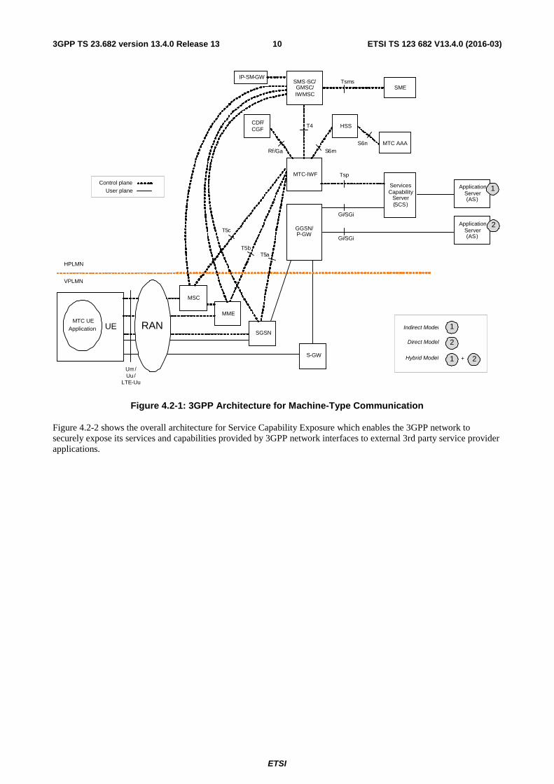
4.2 Architectural Reference Model Figure 4.2-1 shows the architecture for a UE used for MTC connecting to the 3GPP network (UTRAN, E-UTRAN, GERAN, etc.) via the Um/Uu/LTE-Uu interfaces. It also shows the 3GPP network service capability exposure via Tsp to SCS and AS. The architecture covers the various architectural models described in clause 4.1.
ETSI
ETSI TS 123 682 V13.4.0 (2016-03)103GPP TS 23.682 version 13.4.0 Release 13
S6n
Services Capability
Server (SCS )
Gi / SGi
TspControl plane
User plane
Indirect Model
Direct Model
Hybrid Model
GGSN / P -GW
MTC - IWF
SMS -SC / GMSC / IWMSC
2
1
1
T 4
Rf / Ga S 6 m
T5 c
Um /Uu /
LTE -Uu
MTC UE Application
MME
HPLMN
VPLMN
Gi / SGi
SGSN
S -GW
UE
MSC
RAN
T5b T5 a
CDF/ CGF
Tsms
Application Server ( AS )
1
Application Server ( AS )
2
IP -SM - GW
HSS
2+
SME
MTC AAA
Figure 4.2-1: 3GPP Architecture for Machine-Type Communication
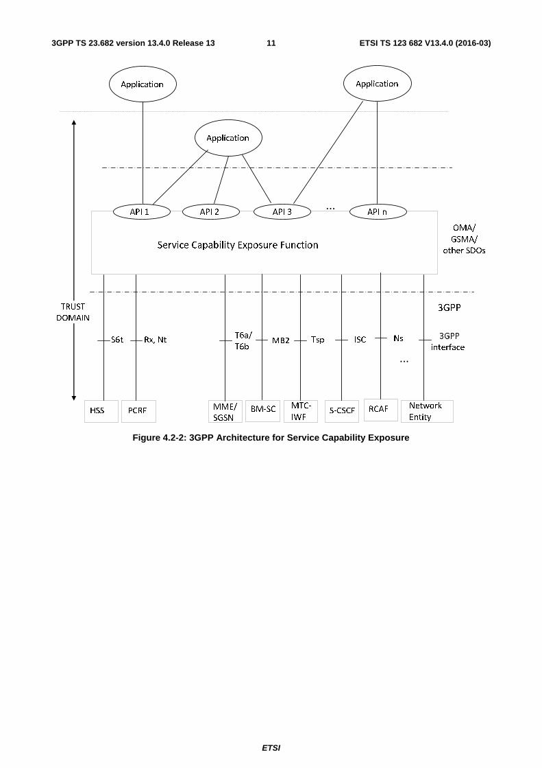
Figure 4.2-2 shows the overall architecture for Service Capability Exposure which enables the 3GPP network to securely expose its services and capabilities provided by 3GPP network interfaces to external 3rd party service provider applications.
ETSI
ETSI TS 123 682 V13.4.0 (2016-03)113GPP TS 23.682 version 13.4.0 Release 13
HSS PCRF MME/
SGSN MTC-
IWF S-CSCF Network
Entity
S6t Rx, Nt T6a/
T6b Tsp ISC
...
3GPP
interface
3GPP TRUST
DOMAIN
Service Capability Exposure Function
API 1 API 2 API 3 API n ...
Application
Application Application
OMA/
GSMA/
other SDOs
MB2
BM-SC RCAF
Ns
Figure 4.2-2: 3GPP Architecture for Service Capability Exposure
ETSI
ETSI TS 123 682 V13.4.0 (2016-03)123GPP TS 23.682 version 13.4.0 Release 13
HSS MME/
SGSN Network
Entity
S6t T6ai/T6bi ... 3GPP
interface
VPLMN
Service Capability
Exposure Function
(SCEF)
HPLMN
Interworking Service
Capability Exposure
Function
(IWK-SCEF)
...
Network
Entity
3GPP
interface
T7
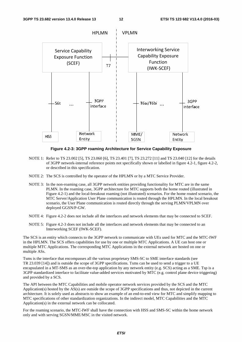
Figure 4.2-3: 3GPP roaming Architecture for Service Capability Exposure
NOTE 1: Refer to TS 23.002 [5], TS 23.060 [6], TS 23.401 [7], TS 23.272 [11] and TS 23.040 [12] for the details of 3GPP network-internal reference points not specifically shown or labelled in figure 4.2-1, figure 4.2-2, or described in this specification.
NOTE 2: The SCS is controlled by the operator of the HPLMN or by a MTC Service Provider.
NOTE 3: In the non-roaming case, all 3GPP network entities providing functionality for MTC are in the same PLMN. In the roaming case, 3GPP architecture for MTC supports both the home routed (illustrated in Figure 4.2-1) and the local-breakout roaming (not illustrated) scenarios. For the home routed scenario, the MTC Server/Application User Plane communication is routed through the HPLMN. In the local breakout scenario, the User Plane communication is routed directly through the serving PLMN/VPLMN over deployed GGSN/P-GW.
NOTE 4: Figure 4.2-2 does not include all the interfaces and network elements that may be connected to SCEF.
NOTE 5: Figure 4.2-3 does not include all the interfaces and network elements that may be connected to an Interworking SCEF (IWK-SCEF).
The SCS is an entity which connects to the 3GPP network to communicate with UEs used for MTC and the MTC-IWF in the HPLMN. The SCS offers capabilities for use by one or multiple MTC Applications. A UE can host one or multiple MTC Applications. The corresponding MTC Applications in the external network are hosted on one or multiple ASs.
Tsms is the interface that encompasses all the various proprietary SMS-SC to SME interface standards (see TR 23.039 [14]) and is outside the scope of 3GPP specifications. Tsms can be used to send a trigger to a UE encapsulated in a MT-SMS as an over-the-top application by any network entity (e.g. SCS) acting as a SME. Tsp is a 3GPP standardized interface to facilitate value-added services motivated by MTC (e.g. control plane device triggering) and provided by a SCS.
The API between the MTC Capabilities and mobile operator network services provided by the SCS and the MTC Application(s) hosted by the AS(s) are outside the scope of 3GPP specifications and thus, not depicted in the current architecture. It is solely used as abstracts to show an example of an end-to-end view for MTC and simplify mapping to MTC specifications of other standardization organizations. In the indirect model, MTC Capabilities and the MTC Application(s) in the external network can be collocated.
For the roaming scenario, the MTC-IWF shall have the connection with HSS and SMS-SC within the home network only and with serving SGSN/MME/MSC in the visited network.
ETSI
ETSI TS 123 682 V13.4.0 (2016-03)133GPP TS 23.682 version 13.4.0 Release 13
The Service Capability Exposure Function (SCEF) is the key entity within the 3GPP architecture for service capability exposure that provides a means to securely expose the services and capabilities provided by 3GPP network interfaces. SCEF functionality may be provided by SCS. MTC-IWF may be co-located with SCEF in which case Tsp functionality would be exposed via API. The interface between SCEF and AS or Applications is outside 3GPP scope. Defining interfaces that permit the SCEF to access services or capabilities at either a new or an existing 3GPP Network Element lies within 3GPP scope. The choice of which protocols to specify for such new 3GPP interfaces (e.g. DIAMETER, RESTful APIs, XML over HTTP, etc.) will depend on multiple factors including but not limited to the needs of that specific interface or ease of exposure of requested information.
The trust domain (see figure 4.2-2) cover entities that are protected by adequate network domain security. The entities and interfaces within the trust domain may all be within one operator's control, or some may be controlled by a trusted business partner which has a trust relationship with the operator e.g. another operator or a 3rd party. The security requirements for the trust domain are out of scope of this document and are assumed to be within SA WG3 scope.
When the SCEF belongs to a trusted business partner of the HPLMN, it is still seen as an HPLMN entity by other HPLMN or VPLMN functional entities invoked by the SCEF (e.g. HSS, MME).
Applications operating in the trust domain may require only a subset of functionalities (e.g. authentication, authorization, etc.) provided by the SCEF. Applications operating in the trust domain can also access network entities (e.g. PCRF), wherever the required 3GPP interface(s) are made available, directly without the need to go through the SCEF.
The Interworking SCEF (IWK-SCEF) is optional. When deployed, the IWK-SCEF is located in the VPLMN.
4.3 Reference points
4.3.1 General
The following 3GPP reference points support the Indirect and Hybrid models of MTC.
NOTE: As further development of the MTC architecture takes place as well as when additional MTC common functionality and features are addressed, further reference points may be added.
4.3.2 List of Reference Points
The description of the MTC and Service Capability Exposure related reference points:
Tsms: Reference point used by an entity outside the 3GPP network to communicate with UEs used for MTC via SMS.
Tsp: Reference point used by a SCS and SCEF to communicate with the MTC-IWF related control plane signalling.
T4: Reference point used by MTC-IWF to route device trigger to the SMS-SC in the HPLMN. T5a: Reference point used between MTC-IWF and serving SGSN. T5b: Reference point used between MTC-IWF and serving MME. T6a: Reference point used between SCEF and serving MME. T6b: Reference point used between SCEF and serving SGSN. T5c: Reference point used between MTC-IWF and serving MSC. T6ai: Reference point used between IWK-SCEF and serving MME. T6bi: Reference point used between IWK-SCEF and serving SGSN. T7: Reference point used between IWK-SCEF and SCEF. S6m: Reference point used by MTC-IWF to interrogate HSS/HLR. S6n: Reference point used by MTC-AAA to interrogate HSS/HLR. S6t: Reference point used between SCEF and HSS. Rx: Reference point used by SCEF and PCRF. Functionality for Rx reference point is specified in
TS 23.203 [27]. Ns: Reference point used between SCEF and RCAF. Nt: Reference point used by SCEF and PCRF. Functionality for Nt reference point is specified in
TS 23.203 [27].
ETSI
ETSI TS 123 682 V13.4.0 (2016-03)143GPP TS 23.682 version 13.4.0 Release 13
NOTE 1: Protocol assumption: User plane communication with SCS, for Indirect model, and AS, for Direct and Hybrid models, is achieved using protocols over Gi and SGi reference points. Control plane protocols over those reference points such as RADIUS/Diameter as specified in TS 29.061 [8] can also be supported towards the SCS.
NOTE 2: In this release of the specification, T5a/b/c reference points are not specified.
NOTE 3: It is assumed that interfaces on the T6ai/T6bi/T7 reference points use the same protocol(s) as interfaces on the T6a/T6b reference points.
4.3.3 Reference Point Requirements
4.3.3.1 Tsp Reference Point Requirements
The Tsp reference point shall fulfil the following requirements:
- connects a MTC-IWF to one or more SCSs;
- supports the following device trigger functionality:
- reception of a device trigger request from SCS that includes an Application Port ID used by the UE to route the trigger internally to the appropriate triggering function;
NOTE 1: The Application Port ID can have different value for different applications.
- report to the SCS the acceptance or non-acceptance of the device trigger request;
- report to the SCS the success or failure of a device trigger delivery; and
- provides congestion/load control information to SCS as part of the response to device trigger requests.
In addition, Domain Name System procedures similar to what is specified in TS 29.303 [9] may be used by the SCS for lookup and selection of which specific MTC-IWF to be used.
NOTE 2: Security requirements can be found in clause 4.8.
4.3.3.2 T4 Reference Point Requirements
The T4 reference point shall fulfil the following requirements:
- connects the MTC-IWF, taking the role of the SME, to SMS-SC inside HPLMN domain;
- supports the following device trigger functionality:
- transfer of device trigger, addressed by either an MSISDN or the IMSI, from MTC-IWF to SMS-SC inside HPLMN domain;
- transfer to the SMS-SC the serving SGSN/MME/MSC identity(ies) along with device trigger when addressed by IMSI; and
- report to MTC-IWF the submission outcome of a device trigger and the success or failure of delivering the device trigger to the UE.
4.3.3.3 T5a/T5b/T5c Reference Point Requirements
The T5a, T5b and T5c reference points shall fulfil the following requirements:
- T5a connects the MTC-IWF to the serving SGSN;
- T5b connects the MTC-IWF to the serving MME;
- T5c connects the MTC-IWF to the serving MSC;
- supports the following device trigger functionality:
ETSI
ETSI TS 123 682 V13.4.0 (2016-03)153GPP TS 23.682 version 13.4.0 Release 13
- transfer of device trigger request to the SGSN/MME/MSC;
- report to MTC-IWF the success or failure of delivering a device trigger to the UE; and
- providing SGSN/MME congestion/load information to the MTC-IWF.
NOTE: In this Release of the specification, T5a/b/c reference points are not specified.
4.3.3.4 S6m Reference Point Requirements
The S6m reference point shall fulfil the following requirements:
- connect the MTC-IWF to HSS/HLR containing subscription and UE related information; and
- support interrogation of HSS/HLR to:
- map E.164 MSISDN or external identifier to IMSI;
- retrieve serving node information for the UE (i.e. serving SGSN/MME/MSC/IP-SM-GW identities); and
- determine if a SCS is allowed to send a device trigger to a particular UE.
NOTE: It is up to stage3 to define interworking between diameter-based s6m and map-based interface to the legacy HLR.
4.3.3.5 S6n Reference Point Requirements
The S6n reference point shall fulfil the following requirements:
- support communication between MTC-AAA and HSS/HLR containing subscription and UE related information; and
- support interrogation of HSS/HLR to:
- map between IMSI and External Identifier(s).
4.3.3.6 T6a/T6b Reference Point Requirements
The T6a and T6b reference points shall fulfil the following requirements:
- T6a connects the SCEF to the serving MME;
- T6b connects the SCEF to the serving SGSN;
- supports the following functionality:
- monitoring event configuration by the SCEF at the serving MME/SGSN;
- monitoring event reporting by the serving MME/SGSN to the SCEF.
4.3.3.7 S6t Reference Point Requirements
The S6t reference point shall fulfil the following requirements:
- connect the SCEF to HSS containing subscription and UE related information;
- monitoring event configuration by the SCEF at the HSS; and
- monitoring event reporting by the HSS to the SCEF.
- configuration of communication pattern parameters by the SCEF to HSS.
4.3.3.8 T6ai/T6bi Reference Point Requirements
The T6ai and T6bi reference points shall fulfil the following requirements:
ETSI
ETSI TS 123 682 V13.4.0 (2016-03)163GPP TS 23.682 version 13.4.0 Release 13
- T6ai connects the IWK-SCEF to the serving MME;
- T6bi connects the IWK-SCEF to the serving SGSN;
- T6ai/T6bi support the following functionality:
- Monitoring Event reporting by the serving MME/SGSN to the IWK-SCEF;
- Forwarding of the Monitoring configuration information from the MME/SGSN to the IWK-SCEF.
4.3.3.9 T7 Reference Point Requirements
The T7 reference point shall fulfil the following requirements:
- connect the IWK-SCEF to the SCEF for Monitoring Event reporting.
4.3.3.10 Ns Reference Point Requirements
The Ns reference points shall fulfil the following requirements:
- Ns connects the SCEF to the RCAF;
- Ns supports the following functionality:
- request for network status by the SCEF;
- report of network status by the RCAF to the SCEF.
4.4 Network Elements
4.4.1 General
The following 3GPP network elements provide functionality to support the Indirect and Hybrid models of MTC.
NOTE: As further development of the MTC architecture takes place as well as when additional MTC common functionality and features are addressed, further network elements may be defined.
4.4.2 MTC-IWF
To support the Indirect and Hybrid models of MTC, one or more instances of an MTC InterWorking Function (MTC-IWF) reside in the HPLMN. A MTC-IWF may be a standalone entity or a functional entity of another network element. The MTC-IWF hides the internal PLMN topology and relays or translates signaling protocols used over Tsp to invoke specific functionality in the PLMN.
The functionality of the MTC-IWF includes the following:
- termination of the Tsp, S6m and Rf/Ga reference points;
- termination of one or more reference points among T4, T5a, T5b and T5c;
- ability to authorize the SCS before communication establishment with the 3GPP network;
- ability to authorize control plane requests from an SCS;
- the following device trigger functionalities:
- reception of a device trigger request from SCS that includes an Application Port ID used by the UE to route the trigger internally to the appropriate triggering function;
- report to the SCS the acceptance or non-acceptance of the device trigger request;
- report to the SCS the success or failure of a device trigger delivery;
ETSI
ETSI TS 123 682 V13.4.0 (2016-03)173GPP TS 23.682 version 13.4.0 Release 13
- may apply MTC-IWF and/or SGSN/MME induced congestion/load control as part of the response to trigger requests; and
- uses a standardised identifier to allow the UE and the network to distinguish an MT message carrying device triggering information from any other type of messages.
- an HSS resolution mechanism for use when multiple and separately addressable HSSs have been deployed by the network operator (see e.g. the SLF / Diameter Proxy agent specified in clause 5.8 TS 23.228 [10]);
- interrogation of the appropriate HSS, when needed for device triggering, to:
- map E.164 MSISDN or External Identifier to IMSI;
- retrieve serving node information for the UE (e.g. serving SGSN/MME/MSC/IP-SM-GW identifier); and
- determine if a SCS is allowed to send a device trigger to a particular UE.
- selection of the most efficient and effective device trigger delivery mechanism and shielding of this detail from SCS based on;
- current UE serving node information from HSS/HLR (e.g. serving MME/SGSN/MSC/IP-SM-GW identifier);
- the device trigger delivery mechanisms supported by the UE;
- the possible device trigger delivery services supported by the HPLMN and, when roaming, VPLMN;
- operator defined device trigger delivery policies, if any; and/or
- optionally, any information received from the SCS.
- protocol translation, if necessary, and forwarding towards the relevant network entity (i.e. serving SGSN/MME/MSC or SMS-SC inside HPLMN domain) of a device trigger request to match the selected trigger delivery mechanism;
- generation of device trigger CDRs with External Identifier and SCS Identifier and forwarding to CDF/CGF over instance of Rf/Ga; and
NOTE 1: CDR generation with or without a device trigger indication by other network entities is not precluded by CDR generation by the MTC-IWF.
- ability for secure communications between the 3GPP network and the SCS.
The architecture shall allow the use of multiple MTC-IWFs within a HPLMN
NOTE 2: This is useful in particular to maintain service upon single MTC-IWF failure.
4.4.3 HSS/HLR
An HSS/HLR supporting device triggering shall support the following functionalities:
- termination of the S6m reference point where MTC-IWFs connect to the HLR/HSS;
- stores and provides to MTC-IWF (and optionally to MTC AAA) the mapping/lookup of E.164 MSISDN or external identifier(s) to IMSI and subscription information used by MTC-IWF for device triggering;
- mapping of E.164 MSISDN or external identifiers to IMSI;
- optionally, mapping from External Identifiers to MSISDN is also provided for legacy SMS infrastructure not supporting MSISDN-less SMS;
- HSS stored "Routing information" including serving node information if available for the UE (e.g. serving SGSN/MME/MSC identifier and registered IP-SM-GW identifier); and
- determine if a SCS is allowed to send a device trigger to a particular UE;
- termination of the S6n reference point;
ETSI
ETSI TS 123 682 V13.4.0 (2016-03)183GPP TS 23.682 version 13.4.0 Release 13
- provides to MTC-AAA the mapping between IMSI and External Identifier(s).
An HSS supporting monitoring events feature shall support the following functionalities:
- termination of the S6t reference point where SCEF connect to the HSS;
- mapping of E.164 MSISDN or external identifiers to IMSI for request received over S6t;
- monitoring event configuration by the SCEF; and
- monitoring event reporting to the SCEF.
An HSS supporting the feature of handling of CP parameters from SCEF to MME shall support the following functionalities:
- termination of the S6t reference point where SCEF connect to the HSS; and
- receiving CP parameters with an External ID; and
- storing the received CP parameters with the corresponding subscriber data; and
- forwarding the received CP parameters with the subscriber data to the corresponding MME.
4.4.4 GGSN/P-GW
A GGSN or P-GW supporting the Indirect or Hybrid model of MTC may support the following functionality
- Based on APN configuration and unavailability of MSISDN and External Identifiers(s) in the GGSN/PGW, the GGSN/PGW either queries a MTC AAA server for retrieval of External Identifier(s) based on IMSI or routes RADIUS/Diameter requests for AAA servers in external PDNs (as specified in TS 29.061 [8]) via a MTC AAA proxy.
4.4.5 SGSN/MME/MSC
SGSN and MME specific functionality to support the Indirect and Hybrid models of MTC includes the following:
- SGSN terminates the T5a reference point;
- MME terminates the T5b reference point;
- MSC terminates the T5c reference point;
- MME terminates the T6a reference point;
- SGSN terminates the T6b reference point;
- receives device trigger from MTC-IWF;
- encapsulates device trigger information in NAS message sent to the UE used for MTC;
- receives device trigger acknowledgement from the triggering UE;
- reports device trigger delivery success/failure status to MTC-IWF;
- may provide SGSN/MME congestion/load information to MTC-IWF;
- monitoring event configuration by the SCEF; and
- monitoring event reporting to the SCEF.
- MME may use the CP parameters for deriving the CN assisted eNodeB parameters. The CP parameters received from the HSS are used by the MME as input to derive the CN assisted eNodeB parameter values.
NOTE: In this Release of the specification, T5a/b/c reference points are not specified.
4.4.6 SMS-SC
ETSI
ETSI TS 123 682 V13.4.0 (2016-03)193GPP TS 23.682 version 13.4.0 Release 13
SMS-SC specific functionality to support the Indirect and Hybrid models of MTC includes the following:
- terminates the T4 reference point where MTC-IWFs connect to the SMS-SC; and
- supports PS-only MT-SMS that can be delivered with IMSI in lieu of E.164 MSISDN; and
- provides the routing information it received from MTC-IWF to SMS-GMSC if needed.
4.4.7 MTC AAA
To support translation of the IMSI to External Identifier(s) at the network egress, an AAA function (MTC AAA) is used in the HPLMN. The MTC AAA may be deployed to return the External Identifier(s) based on IMSI. Alternatively the MTC AAA may be deployed as a RADIUS/Diameter proxy between the GGSN/PGW and the AAA server in the external PDN.
When deployed as an AAA Server, the MTC AAA shall support the following functionalities:
- termination of the S6n reference point where the MTC-AAA communicates with the HLR/HSS;
- return the external identifier(s) corresponding to an IMSI; and
- may query the HSS with IMSI to retrieve the External Identifier(s) and may cache IMSI/External Identifier mapping to avoid multiple HSS queries.
When deployed as an AAA Proxy, the MTC AAA shall support the following functionalities:
- termination of the S6n reference point where the MTC-AAA communicates with the HLR/HSS;
- replace IMSI with an External Identifier for messages to an external AAA server;
- replace External Identifier with IMSI for messages from an external AAA server;
- identifying the destination external AAA server using standard RADIUS/Diameter procedures; and
- optionally, query the HSS with IMSI to retrieve the external identifier(s) and cache IMSI/External Identifier mapping to avoid multiple HSS queries.
4.4.8 Service Capability Exposure Function
The Service Capability Exposure Function (SCEF) provides a means to securely expose the services and capabilities provided by 3GPP network interfaces. The SCEF provides a means for the discovery of the exposed service capabilities. The SCEF provides access to network capabilities through homogenous network application programming interfaces (e.g. Network API) defined by OMA, GSMA, and possibly other standardisation bodies. The SCEF abstracts the services from the underlying 3GPP network interfaces and protocols.
Individual instances of SCEF may vary depending on what service capabilities are exposed and what API features are supported.
The SCEF is always within the trust domain. An application can belong to the trust domain or may lie outside the trust domain. The functionality of the SCEF may include the following:
- Authentication and Authorization:
- Identification of the API consumer,
- Profile management,
- ACL (access control list) management.
NOTE 1: Authentication and Authorization of the requests received from the SCS/AS is outside the scope of 3GPP specifications.
- Ability for the external entities to discover the exposed service capabilities
- Policy enforcement:
ETSI
ETSI TS 123 682 V13.4.0 (2016-03)203GPP TS 23.682 version 13.4.0 Release 13
- Infrastructural Policy: policies to protect platforms and network. An example of which maybe ensuring that a service node such as SMS-SC is not overloaded.
- Business Policy: policies related to the specific functionalities exposed. An example may be number portability, service routing, subscriber consent etc.
- Application Layer Policy: policies that are primarily focused on message payload or throughput provided by an application. An example may be throttling.
- Assurance:
- Integration with O&M systems,
- Assurance process related to usage of APIs.
- Accounting for inter operator settlements.
- Access: issues related to external interconnection and point of contact
- Abstraction: hides the underlying 3GPP network interfaces and protocols to allow full network integration. The following functions are among those that may be supported:
- Underlying protocol connectivity, routing and traffic control,
- Mapping specific APIs onto appropriate network interfaces,
- Protocol translation.
NOTE 2: Abstraction is applied only in cases where required functionality is not natively provided by 3GPP network
The SCEF shall protect the other PLMN entities (e.g. HSS, MME) from requests exceeding the permission arranged in the SLA with the third-party service provider.
When needed, the SCEF supports mapping between information exchanged with SCS/AS (e.g. geographical identifiers) and information exchanged with internal PLMN functions (e.g. cell-Id / ENB-Id / TAI / MBMS SAI , etc.). This mapping is assumed to be provided by the SCEF based on local configuration data.
4.4.9 Interworking SCEF
The Interworking SCEF (IWK-SCEF) is optional. When deployed, the IWK-SCEF is located in the VPLMN for inter-connection with the SCEF of the HPLMN. The Interworking SCEF receives the Monitoring Event Reports from the underlying entities and sends them to the SCEF.
NOTE: In this release the only VPLMN network entities connected towards the IWK-SCEF are the MMEs and SGSNs.
The functionality of the Interworking SCEF may include the following:
- Normalization of reports according to roaming agreement between VPLMN and HPLMN, e.g. change the location granularity (from cell level to a level appropriate for the HPLMN) of Monitoring Event Reports received from the underlying entities; and
- Optionally, generate charging/accounting information:
- For generation of charging/accounting information, the IWK-SCEF receives the Monitoring configuration information as well as the Monitoring Event Report from the underlying nodes.
4.4.10 RAN Congestion Awareness Function
A RCAF supporting network status reporting shall support the following functionalities:
- termination of the Ns reference point where SCEF connects to the RCAF;
- request for one-time or continuous reporting of network status changes by the SCEF; and
ETSI
ETSI TS 123 682 V13.4.0 (2016-03)213GPP TS 23.682 version 13.4.0 Release 13
- report of one-time or continuous network status changes to the SCEF.
4.5 High Level Function
4.5.1 Device Triggering Function
Device Triggering is the means by which a SCS sends information to the UE via the 3GPP network to trigger the UE to perform application specific actions that include initiating communication with the SCS for the indirect model or an AS in the network for the hybrid model. Device Triggering is required when an IP address for the UE is not available or reachable by the SCS/AS.
Device trigger message contains information that allows the network to route the message to the appropriate UE and the UE to route the message to the appropriate application. The information destined to the application, along with the information to route it, is referred to as the Trigger payload. The UE needs to be able to distinguish an MT message carrying device triggering information from any other type of messages.
NOTE: The Trigger payload, for example, upon the reception by the UE possibly provides information to the application that may trigger application related actions. The application in the UE may perform indicated actions, such as for example to initiate immediate or later communication to the SCS/AS, based on the information contained in the Trigger payload.
Device Triggering is subscription based. The subscription provides the information whether a UE is allowed to be triggered by a specific SCS. When device triggers are delivered via MT-SMS the serving nodes MME, SGSN and MSC provide the service towards a specific UE based on the UE's subscription for MT-SMS and other subscription parameters affecting MT-SMS service provision.
Device triggering recall/replace functionality allows a SCS to recall or replace previously submitted trigger messages which are not yet delivered to the UE.
Charging data are collected for the device triggering. The MTC-IWF generates CDRs for the service requester. When device triggers are delivered via MT-SMS then network entities, like MME, SGSN, MSC or SMS-SC generate CDRs for SMS services provided for the mobile subscriber.
4.5.2 PS-only Service Provision
PS-only service provision is providing a UE with all subscribed services via PS domain. PS-only service provision implies a subscription that allows only for services exclusively provided by the PS domain, i.e. packet bearer services and SMS services. The support of SMS services via PS domain NAS is a network deployment option and may depend also on roaming agreements. Therefore, a subscription intended for PS-only service provision may allow also for SMS services via CS domain to provide a UE with SMS services in situations when serving node or network don't support SMS via PS domain NAS. The functionality that enables PS-only service provision is described in TS 23.060 [6] and TS 23.272 [11].
The functionality that enables PS-only service provision for SMS delivery in IMS is described in TS 23.204 [13].
4.5.3 Core Network assisted RAN parameters tuning
Core Network assisted RAN parameters tuning aids the RAN in optimizing the setting of RAN parameters. See TS 23.401 [7] for details.
4.5.4 UE Power Saving Mode
A UE may adopt the PSM for reducing its power consumption. That mode is similar to power-off, but the UE remains registered with the network and there is no need to re-attach or re-establish PDN connections. A UE in PSM is not immediately reachable for mobile terminating services. A UE using PSM is available for mobile terminating services during the time it is in connected mode and for the period of an Active Time that is after the connected mode. The connected mode is caused by a mobile originated event like data transfer or signalling, e.g. after a periodic TAU/RAU procedure. PSM is therefore intended for UEs that are expecting only infrequent mobile originating and terminating services and that can accept a corresponding latency in the mobile terminating communication.
ETSI
ETSI TS 123 682 V13.4.0 (2016-03)223GPP TS 23.682 version 13.4.0 Release 13
For mobile terminated data while a UE is in PSM, the functions for High latency communication may be used as described in clause 4.5.7.
PSM has no support in the CS domain on the network side. PSM should only be used by UEs using the PS domain, SMS and mobile originated IMS or CS services. A UE that uses mobile terminated CS services other than SMS should not use PSM as the CS domain does not provide support for mobile terminated CS voice services to UEs that are in PSM. A UE that uses delay tolerant mobile terminated IMS services other than SMS should not request for PSM unless IMS uses the functions for High latency communication as described in clause 4.5.7.
NOTE 1: The frequency of keep-alive messages on Gm impacts the possibility to use IMS services for UEs applying PSM.
Applications that want to use the PSM need to consider specific handling of mobile terminating services or data transfers. A network side application may send an SMS or a device trigger to trigger an application on UE to initiate communication with the SCS/AS, which is delivered when the UE becomes reachable. Alternatively a network side application may request monitoring of reachability for data to receive a notification when it is possible to send downlink data immediately to the UE, which is when the UE becomes reachable for downlink data transfer. Alternatively, if an SCS/AS has periodic downlink data, it is more efficient when the UE initiates communication with the SCS/AS to poll for downlink data with that period. For either of the options to work, the UE should request an Active Time that is together with the time being in connected mode long enough to allow for potential mobile terminated service or data delivery, e.g. to deliver an SMS.
When the UE wants to use the PSM it shall request an Active Time value during every Attach and TAU/RAU procedures. If the network supports PSM and accepts that the UE uses PSM, the network confirms usage of PSM by allocating an Active Time value to the UE. The network takes the UE requested value, the Reachability Time, if provided with the Insert Subscriber Data message from HSS, and any local MME/SGSN configuration into account for determining the Active Time value that is allocated to the UE. If the UE wants to change the Active Time value, e.g. when the conditions are changed in the UE, the UE consequently requests the value it wants in the TAU/RAU procedure.
NOTE 2: The minimum recommended length for the Active Time is the time allowing for the 'msg waiting flag' in the MME/SGSN to trigger the SMSC via the HSS to deliver an SMS to the MME/SGSN, e.g. 2 DRX cycles plus 10 seconds.
An Active Time may be shorter than the time estimated for delivering a waiting SMS to the UE in NOTE 1 above, e.g. 0 seconds. If the MME/SGSN allocates such a shorter Active Time to the UE, the MME/SGSN (for signalling only connections and if the 'msg waiting flag' is set) and the RAN (for connections with RAB(s) set up) should be configured to keep the connection with the UE sufficiently long such that a waiting SMS can be delivered.
NOTE 3: The RAN configuration of RAB connection times need not differentiate between UEs.
If the MME/SGSN is requested to monitor for Reachability for Data, the MME/SGSN (for signalling only connections) and the RAN (for connections with RAB(s) set up) should keep the connection for the Max Response Time less the Active Time, if Max Response Time is provided with the Insert Subscriber Data message from HSS. Otherwise a configured default Max Response Time is assumed by the MME/SGSN.
The UE is in PSM until a mobile originated event (e.g. periodic RAU/TAU, mobile originated data or detach) requires the UE to initiate any procedure towards the network. In Attach and RAU/TAU procedures a PSM capable UE may request a periodic TAU/RAU Timer value suitable for the latency/responsiveness of the mobile terminated services. If the UE wants to change the periodic TAU/RAU Timer value, e.g. when the conditions are changed in the UE, the UE consequently requests the value it wants in the TAU/RAU procedure.
NOTE 4: If the UE or application performs any periodic uplink data transfer with a periodicity similar to the Periodic TAU/RAU Timer value, it preferably requests a Periodic TAU/RAU Timer value that is at least slightly larger than the data transfer period to avoid periodic TAU/RAU procedures that would increase power consumption.
Any timers and conditions that remain valid during power-off, e.g. NAS-level back-off timers, apply in the same way during PSM. The UE may leave the PSM any time, e.g. for mobile originated communications.
If the network confirms the usage of PSM to a UE, the network shall not activate the ISR for such UE.
The specific procedure handling is described in TS 23.060 [6] and TS 23.401 [7].
ETSI
ETSI TS 123 682 V13.4.0 (2016-03)233GPP TS 23.682 version 13.4.0 Release 13
4.5.5 Group Message Delivery
Group message delivery is intended to efficiently distribute the same content to the members of a group that are located in a particular geographical area on request of the SCS/AS via SCEF.
The specific procedure handling for group message delivery using MBMS is described in clause 5.5.1. The group message delivery using MBMS has limited applicability and does not support all the scenarios, e.g. UEs not supporting MBMS, UEs located in areas where MBMS is not deployed.
4.5.6 Monitoring Events
4.5.6.1 General
The Monitoring Events feature is intended for monitoring of specific events in 3GPP system and making such monitoring events information available via the SCEF. It is comprised of means that allow the identification of the 3GPP network element suitable for configuring the specific events, the event detection, and the event reporting to the authorised users, e.g. for use by applications or logging, etc. If such an event is detected, the network might be configured to perform special actions, e.g. limit the UE access. Configuration and reporting of the following monitoring events may be supported:
- Monitoring the association of the UE and UICC and/or new IMSI-IMEI-SV association;
- UE reachability;
- Location of the UE, and change in location of the UE;
NOTE 1: Location granularity for event request, or event report, or both could be at cell level (CGI/ECGI), TA/RA level or other formats e.g. shapes (e.g. polygons, circles, etc.) or civic addresses (e.g. streets, districts, etc.).
- Loss of connectivity;
- Communication failure;
- Roaming status (i.e. Roaming or No Roaming) of the UE, and change in roaming status of the UE; and
NOTE 2: Roaming status means whether the UE is in HPLMN or VPLMN.
- Number of UEs present in a geographical area; and
- Availability after DDN failure.
To support monitoring features in roaming scenarios, a roaming agreement needs to be made between the HPLMN and the VPLMN. The set of capabilities required for monitoring may be accessible via different 3GPP interfaces/nodes. Selection of 3GPP interface(s) to configure/report the event is dependent on the type of the event, operator configuration, required frequency of event reporting, application provided parameters in monitoring event request, etc.
Support for Monitoring Events can be offered either via HSS, MME/SGSN (as described in clause 4.5.6.2) or via PCRF (as described in clause 4.5.6.3). Based on operator policies, it shall be possible to configure Monitoring Events such that some Monitoring Event follows procedures in clause 4.5.6.2 while another Monitoring Event follows procedures in clause 4.5.6.3. SCEF shall not enable a given Monitoring Event for the same UE via both HSS/MME/SGSN, and PCRF.
NOTE 3: If the configuration of Monitoring Events uses signalling which was specified as part of another feature than the Monitoring feature, then the requirements on the HSS, MME/SGSN and PCRF as specified by that feature apply e.g. not to generate accounting information, not to verify SLA etc.
4.5.6.2 Monitoring Events via HSS and MME/SGSN
Monitoring Events via the HSS and the MME/SGSN enables SCEF to configure a given Monitor Event at HSS or MME/SGSN, and reporting of the event via HSS and/or MME/SGSN. Depending on the specific monitoring event or information, it is either the MME/SGSN or the HSS that is aware of the monitoring event or information and makes it available via the SCEF.
ETSI
ETSI TS 123 682 V13.4.0 (2016-03)243GPP TS 23.682 version 13.4.0 Release 13
The procedures for requesting specific monitoring information or event reports as well as the report procedures are described in clause 5.6.
4.5.6.3 Monitoring Events via PCRF
Monitoring Events via the PCRF enables the SCEF to retrieve the location information and to report communication failure of a UE. The SCEF acting as AF shall have an active Rx session to enable the PCRF to report these events. The procedure is defined in TS 23.203 [27] clause 6.2.3.
The UE location information, provided over Rx, may include a time stamp to indicate when the UE was last-known to be in that location, i.e. if the current location or the last-known location is provided. The UE location information is reported at the time the Rx session is established, modified or terminated. The subscription to UE location information is not persistent across Rx sessions. The UE location information is only provided for 3GPP IP-CAN type or for Trusted WLAN access (S2a).
The reporting of communication failure refers to the reporting of RAN/NAS release cause codes according to TS 23.401 [7], TS 23.060 [6], and TWAN/UWAN release causes according to TS 23.402 [26]. Once the RAN/NAS or TWAN/UWAN release cause codes are reported to the PCRF, the PCRF reports it to the SCEF according to TS 23.203 [27] for applicable IP-CAN types and RAT types listed in TS 23.203 [27].
4.5.6.4 Charging Principles
The support of accounting functionality for Monitoring Events is optional. Depending on operator configuration the MME, SGSN, SCEF and IWK-SCEF support accounting functionality for Monitoring Events.
Accounting information shall be generated for every Monitoring Event configuration request, Monitoring Event modification request, and implicit or explicit Monitoring Event deletion request. The accounting information shall also be generated for Monitoring Event response messages.
NOTE 1: The requirement to generate Accounting information applies for messages which have been defined as part of the Monitoring function e.g. Monitoring Request, Monitoring Indication.
Accounting information, e.g. number of successful Monitoring Requests, number of failed Monitoring Requests, number of Monitoring Event Reports generated due to a configured Monitoring Event, is collected by the MME, SGSN, SCEF, and IWK-SCEF for intra-operator use, and also for inter-operator settlements.
NOTE 2: The details of the required accounting information are outside the scope of this specification.
The Monitoring Event feature shall support charging in accordance with TS 32.240 [28]. Interaction with Offline Charging systems shall be supported.
4.5.7 High latency communication
Functions for High latency communication may be used to handle mobile terminated (MT) communication with UEs being unreachable while using power saving functions e.g. UE Power Saving Mode (see clause 4.5.4) or extended idle mode DRX (see clause 4.5.13) depending on operator configuration. "High latency" refers to the initial response time before normal exchange of packets is established. That is, the time it takes before a UE has woken up from its power saving state and responded to the initial downlink packet(s).
High latency communication is handled by an extended buffering of downlink data in the Serving GW controlled by the MME/S4-SGSN or in the Gn/Gp-SGSN. The MME/S4-SGSN asks the Serving GW to buffer downlink data until the UE is expected to wake up from its power saving state. The Gn/Gp-SGSN similarly buffers downlink data until the UE is expected to wake up from its power saving state. If a Serving GW change or a Gn/Gp-SGSN change is invoked, the buffered packets are forwarded and will not be lost. The number of packets to buffer is decided by the Serving GW or Gn/Gp-SGSN, but the MME/S4-SGSN may optionally provide a suggestion for the number of downlink packets to be buffered based on e.g. subscription and/or information provided by the SCS/AS during the configuration of the event.
High latency communication may also be handled by notification procedures (see clause 5.7), when an MME/S4-SGSN is used (i.e., this procedure does not apply to a Gn/Gp-SGSN). The SCS/AS requests notification when a UE wakes up from its power saving state and sends downlink data to the UE when the UE is reachable. Especially for infrequent mobile terminated communication this may be suitable. This notification procedure is available based on two different monitoring events:
ETSI
ETSI TS 123 682 V13.4.0 (2016-03)253GPP TS 23.682 version 13.4.0 Release 13
- Monitoring event: UE Reachability; or
- Monitoring event: Availability after DDN failure.
An SCS/AS may request a one-time "UE Reachability" notification when it wants to send data to the UE. Alternatively the SCS/AS may request repeated "Availability after DDN failure" notifications where each notification is triggered by a DDN failure i.e. the SCS/AS sends a downlink packet which is discarded by Serving GW but which triggers the MME/SGSN to send an event notification to the SCS/AS next time the UE wakes up.
The length of the power saving intervals used by the network decides the maximum latency for a UE. An SCS/AS, which has a specific requirement on the maximum latency for UEs it communicates with, may provide its maximum latency requirement to the network. This is done either by interaction with the application in the UE and setting of appropriate time values in the UE (e.g. periodic RAU/TAU timer) for the Power Saving Mode, or by providing the maximum latency at the configuration of the "UE reachability" monitoring event (if used) (see clause 5.7).
The tools for High latency communication make the behaviour of the 3GPP network predictable when sending mobile terminated data to UEs applying power saving functions. The network will deliver downlink packets with high reliability for both stationary and mobile UEs when the UE wakes up from its power saving state. Therefore SCS/AS can adapt its retransmissions to reduce the load on both the SCS/AS itself and the network.
4.5.8 Support of informing about potential network issues
The SCS/AS may request the SCEF for being notified about the network status in a geographical area. The SCS/AS can request for a one-time reporting of network status or a continuous reporting of network status changes.
4.5.9 Resource management of background data transfer
The 3rd party SCS/AS requests a time window and related conditions from the SCEF for background data transfer to a set of UEs via the Nt interface. The SCS/AS request shall contain the SCS/AS identifier, the volume of data expected to be transferred per UE, the expected amount of UEs, the desired time window and optionally, network area information. The SCEF passes this information to a selected PCRF. The PCRF shall determine one or more transfer policies each including a recommended time window for the data transfer together with a maximum aggregated bitrate for the expected volume of data and a reference to the applicable charging rate during the time window and provide them to the SCEF together with a reference ID. The SCEF shall forward the reference ID and the transfer policies to the 3rd party SCS/AS. If more than one transfer policy was received, the 3rd party SCS/AS needs to select one of them and inform the SCEF about the selected transfer policy (which forwards it to the PCRF). If this is not done, none of the transfer policies provided by the operator will be valid.
NOTE 1: The maximum aggregated bitrate (optionally provided in a transfer policy) is not enforced in the network. The operator may apply offline CDRs processing (e.g. combining the accounted volume of the involved UEs for the time window) to determine whether the maximum aggregated bitrate for the set of UEs was exceeded by the ASP and charge the excess traffic differently.
NOTE 2: It is assumed that the 3rd party SCS/AS is configured to understand the reference to a charging rate based on the agreement with the operator.
After having negotiated the time window, the SCS/AS shall provide the reference ID to the PCRF for each UE individually together with the SCS/AS session information via the Rx interface. The PCRF retrieves the corresponding transfer policy from the SPR. The PCRF derives the PCC rules for the background data transfer according to this transfer policy and triggers PCC procedures according to 3GPP TS 23.203 [27] to provide the respective policing and charging information to the PCEF.
NOTE 3: The SCS/AS will typically contact the PCRF for the individual UEs to request sponsored connectivity for the background data transfer.
NOTE 4: A transfer policy is only valid until the end of its time window. The removal of outdated transfer policies from the SPR is up to implementation.
ETSI
ETSI TS 123 682 V13.4.0 (2016-03)263GPP TS 23.682 version 13.4.0 Release 13
4.5.10 E-UTRAN network resource optimizations based on communication patterns provided to the MME
Predictable communication patterns (CP) of a UE may be provided by the Application Server to the SCEF in order to enable network resource optimizations for such UE(s). The SCEF filters the CP parameters and forwards them to the HSS, which provides them to the MME. The MME may use the CP parameters as input to derive the CN assisted eNodeB parameters as described in TS 23.401 [7]. This feature is applicable to UEs served over the E-UTRAN access.
4.5.11 Support of setting up an AS session with required QoS
The 3rd party SCS/AS may request that a data session to a UE that is served by the 3rd party service provider (AS session) is set up with a specific QoS (e.g. low latency or jitter) and priority handling. This functionality is exposed via the SCEF towards the SCS/AS.
The SCS/AS can request the network to provide QoS for the AS session based on the application and service requirements with the help of a reference to pre-defined QoS information.
NOTE 1: The concept of referencing a pre-defined QoS is specified by OMA in the RESTful Network API for Quality of Service. The pre-defined QoS is part of the SLA between the operator and the 3rd party SCS/AS.
When the SCEF receives the request from the SCS/AS to provide QoS for an AS session, the SCEF acts as an AF per TS 23.203 [27] specifications and transfers the request to provide QoS for an AS session to the PCRF via the Rx interface.
NOTE 2: An SLA has to be in place defining the possible QoS levels and their charging rates. For each of the possible pre-defined QoS information sets, the PCRF needs to be configured with the corresponding QoS parameters and their values as well as the appropriate Rating-Group (or receive this information from the SPR).
NOTE 3: The reference to pre-defined QoS information is transferred by existing Rx parameters. Before the reference to pre-defined QoS information is forwarded, the SCEF can perform a mapping from the name space of the 3rd party AS to the name space of the operator.
4.5.12 Change the chargeable party at session set-up or during the session
The SCS/AS may request the SCEF to start or stop sponsoring a data session for a UE that is served by the 3rd party service provider (AS session), i.e. to realize that either the 3rd party service provider is charged for the traffic (start) or not (stop). The SCS/AS may request to be set as the chargeable party, i.e. sponsoring the traffic, either at AS session set-up or to change it during an ongoing AS session. The SCEF acts as an AF and existing functionality defined in TS 23.203 [27] for sponsored data connectivity is used to support this functionality.
4.5.13 Extended idle mode DRX
4.5.13.1 General
The UE and the network may negotiate over non-access stratum signaling the use of extended idle mode DRX for reducing its power consumption, while being available for mobile terminating data and/or network originated procedures within a certain delay dependent on the DRX cycle value.
Applications that want to use extended idle mode DRX need to consider specific handling of mobile terminating services or data transfers, and in particular they need to consider the delay tolerance of mobile terminated data. A network side application may send mobile terminated data, an SMS, or a device trigger, and needs to be aware that extended idle mode DRX may be in place. A UE should request for extended idle mode DRX only when all expected mobile terminating communication is tolerant to delay.
A UE that uses mobile terminated CS services other than SMS should not request for extended idle mode DRX as the CS domain does not provide support for mobile terminated CS voice services to UEs that are in extended idle mode DRX. A UE that uses delay tolerant mobile terminated IMS services other than SMS should not request for extended idle mode DRX unless IMS uses the functions for High latency communication as described in clause 4.5.7.
ETSI
ETSI TS 123 682 V13.4.0 (2016-03)273GPP TS 23.682 version 13.4.0 Release 13
NOTE: The frequency of keep-alive messages on Gm impacts the possibility to use IMS services for UEs applying extended idle mode DRX.
In order to negotiate the use of extended idle mode DRX, the UE requests extended idle mode DRX parameters during attach procedure and RAU/TAU procedure. The SGSN/MME may reject or accept the UE request for enabling extended idle mode DRX. In case the SGSN/MME accepts the extended idle mode DRX, the SGSN/MME based on operator policies may also provide different values of the extended idle mode DRX parameters than what was requested by the UE. If the SGSN/MME accepts the use of extended idle mode DRX, the UE applies extended idle mode DRX based on the received extended idle mode DRX parameters. If the UE does not receive extended idle mode DRX parameters in the relevant accept message because the SGSN/MME rejected its request or because the request was received by SGSN/MME not supporting extended idle mode DRX, the UE shall apply its regular discontinuous reception as defined in TS 23.401 [7] clause 5.13.
The specific negotiation procedure handling is described in TS 23.060 [6] and TS 23.401 [7].
If a UE requests via NAS both to enable PSM (requesting an active time and possibly a periodic TAU timer) and extended idle mode DRX (with a specific extended idle mode DRX cycle value), it is up to the SGSN/MME to decide whether to:
1. Enable only PSM, i.e. not accept the request for extended idle mode DRX.
2. Enable only extended idle mode DRX, i.e. not accept the request for an active time.
3. Enable both PSM (i.e. provide an active time) and extended idle mode DRX (i.e. provide an extended idle mode DRX parameters).
The decision between the three above, and which active time, periodic TAU timer and/or extended idle mode DRX cycle value to provide to the UE, are implementation dependent, based on local configuration, and possibly other information available in the SGSN/MME. The method selected is then used until the next Attach or RAU/TAU procedure is initiated, when a new decision may be made. If both extended idle mode DRX and PSM are enabled, the extended idle mode DRX cycle should be set in order to have multiple paging occasions while the active timer is running.
In the specific case when the PSM active time provided by the UE is greater than the extended idle mode DRX cycle value provided by the UE, the SGSN/MME may enable both PSM and extended idle mode DRX. This allows a UE to minimize power consumption during the active time e.g. when the active time is slightly longer than typical active time values for example in the order of several minutes.
In case extended idle mode DRX is enabled, the network handles mobile terminated data using high latency communication feature, according to clause 4.5.7, GTP-C retransmissions as described in TS 23.060 [6] and TS 23.401 [7], and applies techniques to handle mobile terminated SMS according to TS 23.272 [11] and location services according to TS 23.271 [33].
4.5.13.2 Paging for extended idle mode DRX in UTRAN
The procedure makes use of the regular DRX cycle mechanism for determination of Paging Occasions (POs) (see 3GPP TS 25.304 [34]) in conjunction with a new TeDRX timer and a means to synchronize the start of the TeDRX timer with a time reference referred to here as Tref. The TeDRX timer is set to the extended Idle mode DRX cycle value negotiated earlier on NAS level. At TeDRX expiry i.e. when the extended Idle mode DRX cycle elapses the UE monitors the network for paging using regular DRX parameters.
CN and UE start the extended TeDRX timer at transmission and reception, respectively, of the Attach Accept or RAU Accept message where the relevant extended Idle mode DRX parameters are provided. In other words, Tref corresponds in the CN to the instant when RAU Accept message is sent and in the UE to the instant when the respective Accept message is received.
The TeDRX timer is maintained and used only when the Attach/RAU procedure was successfully executed and independent of UE's PMM state, i.e. transitions between Idle and Connected mode do not affect the TeDRX timer.
In order to improve paging reliability e.g. to avoid paging misses due to cell reselection or due to imperfect synchronization of the Tref parameter in the UE and the SGSN, a Paging Transmission Window Time (PTW) described by its duration TPTW is introduced. During PTW the UE monitors the network for paging when the extended Idle mode DRX cycle based on the extended Idle mode DRX value expires. During the PTW there may be multiple opportunities to page the UE which monitors the network for paging using regular DRX parameters.
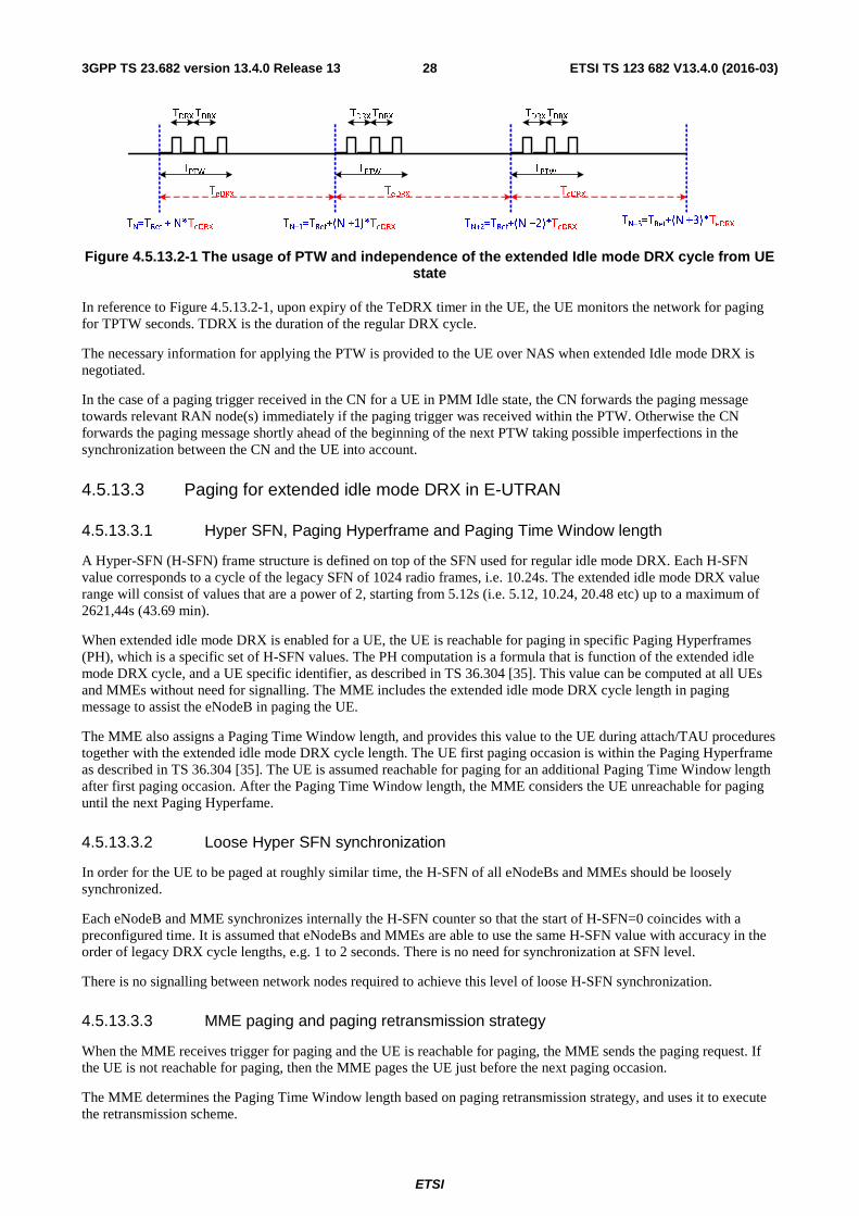
ETSI
ETSI TS 123 682 V13.4.0 (2016-03)283GPP TS 23.682 version 13.4.0 Release 13
TeDRX
TN=TRef + N* TeDRX TN+1=TRef +(N +1)*TeDRX
TPTW
TN+2= TRef+(N +2)*TeDRX
TDRXTDRX
TeDRX
TPTW
TeDRX
TPTW
TDRXTDRX TDRXTDRX
TN+3=TRef +(N +3)*TeDRX
Figure 4.5.13.2-1 The usage of PTW and independence of the extended Idle mode DRX cycle from UE state
In reference to Figure 4.5.13.2-1, upon expiry of the TeDRX timer in the UE, the UE monitors the network for paging for TPTW seconds. TDRX is the duration of the regular DRX cycle.
The necessary information for applying the PTW is provided to the UE over NAS when extended Idle mode DRX is negotiated.
In the case of a paging trigger received in the CN for a UE in PMM Idle state, the CN forwards the paging message towards relevant RAN node(s) immediately if the paging trigger was received within the PTW. Otherwise the CN forwards the paging message shortly ahead of the beginning of the next PTW taking possible imperfections in the synchronization between the CN and the UE into account.
4.5.13.3 Paging for extended idle mode DRX in E-UTRAN
4.5.13.3.1 Hyper SFN, Paging Hyperframe and Paging Time Window length
A Hyper-SFN (H-SFN) frame structure is defined on top of the SFN used for regular idle mode DRX. Each H-SFN value corresponds to a cycle of the legacy SFN of 1024 radio frames, i.e. 10.24s. The extended idle mode DRX value range will consist of values that are a power of 2, starting from 5.12s (i.e. 5.12, 10.24, 20.48 etc) up to a maximum of 2621,44s (43.69 min).
When extended idle mode DRX is enabled for a UE, the UE is reachable for paging in specific Paging Hyperframes (PH), which is a specific set of H-SFN values. The PH computation is a formula that is function of the extended idle mode DRX cycle, and a UE specific identifier, as described in TS 36.304 [35]. This value can be computed at all UEs and MMEs without need for signalling. The MME includes the extended idle mode DRX cycle length in paging message to assist the eNodeB in paging the UE.
The MME also assigns a Paging Time Window length, and provides this value to the UE during attach/TAU procedures together with the extended idle mode DRX cycle length. The UE first paging occasion is within the Paging Hyperframe as described in TS 36.304 [35]. The UE is assumed reachable for paging for an additional Paging Time Window length after first paging occasion. After the Paging Time Window length, the MME considers the UE unreachable for paging until the next Paging Hyperfame.
4.5.13.3.2 Loose Hyper SFN synchronization
In order for the UE to be paged at roughly similar time, the H-SFN of all eNodeBs and MMEs should be loosely synchronized.
Each eNodeB and MME synchronizes internally the H-SFN counter so that the start of H-SFN=0 coincides with a preconfigured time. It is assumed that eNodeBs and MMEs are able to use the same H-SFN value with accuracy in the order of legacy DRX cycle lengths, e.g. 1 to 2 seconds. There is no need for synchronization at SFN level.
There is no signalling between network nodes required to achieve this level of loose H-SFN synchronization.
4.5.13.3.3 MME paging and paging retransmission strategy
When the MME receives trigger for paging and the UE is reachable for paging, the MME sends the paging request. If the UE is not reachable for paging, then the MME pages the UE just before the next paging occasion.
The MME determines the Paging Time Window length based on paging retransmission strategy, and uses it to execute the retransmission scheme.
ETSI
ETSI TS 123 682 V13.4.0 (2016-03)293GPP TS 23.682 version 13.4.0 Release 13
If the UE is unreachable for paging, then MME may follow clause 4.5.7 "High latency communication" for functionality related to Mobile Terminated communication with high latency.
4.6 Identifiers
4.6.1 General
Identifiers relevant for the 3GPP network are specified in TS 23.003 [4].
4.6.2 External Identifier
A subscription used for MTC has one IMSI and may have one or several External Identifier(s) that are stored in the HSS.
NOTE 1: If several External Identifiers are mapped to one IMSI, some functions might not work in this release of the specification.
External Identifier shall be globally unique. It shall have the following components:
a. Domain Identifier: identifies a domain that is under the control of a Mobile Network Operator (MNO). The Domain Identifier is used to identify where services provided by the operator network can be accessed (e.g. MTC-IWF provided services). An operator may use different domain identifiers to provide access to different services.
b. Local Identifier: Identifier used to derive or obtain the IMSI. The Local Identifier shall be unique within the applicable domain. It is managed by the Mobile Network Operator.
NOTE 2: Use of External Identifiers is not restricted to MTC only.
NOTE 3: Use of IMSI outside the 3GPP operator domain is dependent on the operator policy.
4.7 Addressing For UEs used for Machine-Type Communications (MTC) IP Addressing principles and solutions for different scenarios are described in clause 5 of TS 23.221 [21].
4.8 Security Aspects
4.8.1 Security Requirements
4.8.1.0 General
Security requirements are described in TS 33.187 [25].
4.8.1.1 Void
4.8.1.2 Void
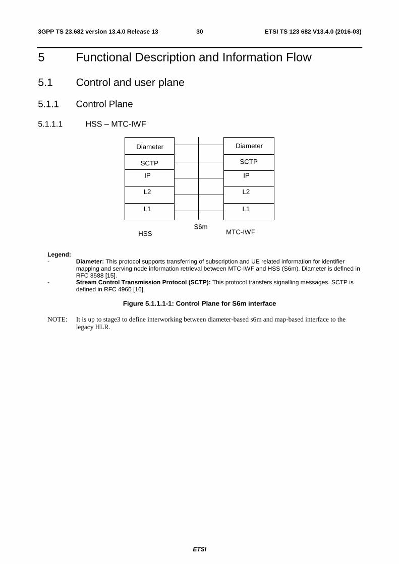
ETSI
ETSI TS 123 682 V13.4.0 (2016-03)303GPP TS 23.682 version 13.4.0 Release 13
5 Functional Description and Information Flow
5.1 Control and user plane
5.1.1 Control Plane
5.1.1.1 HSS – MTC-IWF
SCTP
L2
L1
IP
L2
L1
IP
S6m HSS MTC-IWF
Diameter Diameter
SCTP
Legend: - Diameter: This protocol supports transferring of subscription and UE related information for identifier
mapping and serving node information retrieval between MTC-IWF and HSS (S6m). Diameter is defined in RFC 3588 [15].
- Stream Control Transmission Protocol (SCTP): This protocol transfers signalling messages. SCTP is defined in RFC 4960 [16].
Figure 5.1.1.1-1: Control Plane for S6m interface
NOTE: It is up to stage3 to define interworking between diameter-based s6m and map-based interface to the legacy HLR.
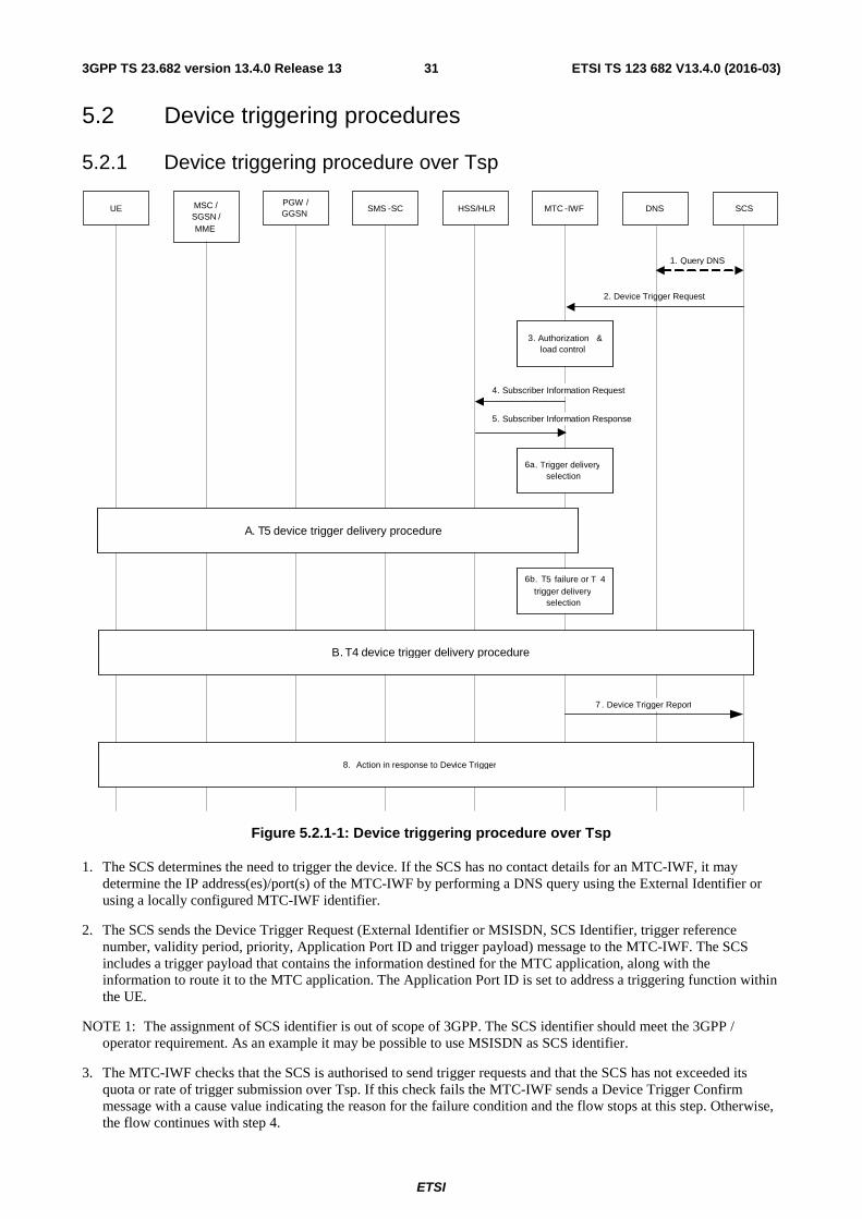
ETSI
ETSI TS 123 682 V13.4.0 (2016-03)313GPP TS 23.682 version 13.4.0 Release 13
5.2 Device triggering procedures
5.2.1 Device triggering procedure over Tsp
UE MSC /
SGSN / MME
PGW / GGSN HSS/HLR SCS DNS SMS - SC MTC - IWF
2. Device Trigger Request
A. T 5 device trigger delivery procedure
7 . Device Trigger Report
B. T 4 device trigger delivery procedure
5. Subscriber Information Response
1 . Query DNS
4. Subscriber Information Request
8. Action in response to Device Trigger
6 a . Trigger delivery selection
3. Authorization & load control
6 b . T5 failure or T 4 trigger delivery
selection
Figure 5.2.1-1: Device triggering procedure over Tsp
1. The SCS determines the need to trigger the device. If the SCS has no contact details for an MTC-IWF, it may determine the IP address(es)/port(s) of the MTC-IWF by performing a DNS query using the External Identifier or using a locally configured MTC-IWF identifier.
2. The SCS sends the Device Trigger Request (External Identifier or MSISDN, SCS Identifier, trigger reference number, validity period, priority, Application Port ID and trigger payload) message to the MTC-IWF. The SCS includes a trigger payload that contains the information destined for the MTC application, along with the information to route it to the MTC application. The Application Port ID is set to address a triggering function within the UE.
NOTE 1: The assignment of SCS identifier is out of scope of 3GPP. The SCS identifier should meet the 3GPP / operator requirement. As an example it may be possible to use MSISDN as SCS identifier.
3. The MTC-IWF checks that the SCS is authorised to send trigger requests and that the SCS has not exceeded its quota or rate of trigger submission over Tsp. If this check fails the MTC-IWF sends a Device Trigger Confirm message with a cause value indicating the reason for the failure condition and the flow stops at this step. Otherwise, the flow continues with step 4.
ETSI
ETSI TS 123 682 V13.4.0 (2016-03)323GPP TS 23.682 version 13.4.0 Release 13
4. The MTC-IWF sends a Subscriber Information Request (External Identifier or MSISDN and SCS Identifier) message to the HSS/HLR to determine if SCS is authorized to trigger the UE, to resolve the External Identifier or MSISDN to IMSI and retrieve the related HSS stored "Routing information" including the identities of the UE's serving CN node(s).
NOTE 2: The MTC-IWF may cache authorization and routing information for the UE. However, this may increase the probability of trigger delivery attempt failures when the cached serving node information is stale.
NOTE 3: Optionally, mapping from External Identifiers to MSISDN is also provided for legacy SMS infrastructure not supporting MSISDN-less SMS.
5. The HSS/HLR sends the Subscriber Information Response (IMSI and/or MSISDN and related "Routing information" including the serving node(s) identities, cause) message. HSS/HLR policy (possibly dependent on the VPLMN ID) may influence which serving node identities are returned. If the cause value indicates the SCS is not allowed to send a trigger message to this UE, or there is no valid subscription information, or "Absent subscriber" is received from HSS and the validity period of this trigger message is set to zero, the MTC-IWF sends a Device Trigger Confirm message with a cause value indicating the reason for the failure condition and the flow stops at this step. Otherwise this flow continues with step 6a.
6a. The MTC-IWF selects trigger delivery procedure based on the information received from HSS/HLR and local policy. If T5 delivery procedure is selected, MTC-IWF attempts T5 trigger delivery procedure.
NOTE 2: The T5 delivery is not supported in this version of the specification.
6b. If T5 delivery is unsuccessful or not supported by the serving nodes(s) or by the UE or if T4 delivery is selected during step 6a, the MTC-IWF attempts T4 trigger delivery procedure according to clause 5.2.2. Otherwise, this flow continues with step 7.
7. The MTC-IWF sends the Device Trigger Report (External Identifier or MSISDN and trigger reference number) message to the SCS with a cause value indicating the trigger delivery outcome (e.g. succeeded, unknown or failed and the reason for the failure). The MTC-IWF generates the necessary CDR information including the External Identifier or MSISDN and SCS Identifier.
8. In response to the received device trigger, the UE takes specific actions that take into consideration the content of the trigger payload. This response typically involves initiation of immediate or later communication with the SCS or an AS.
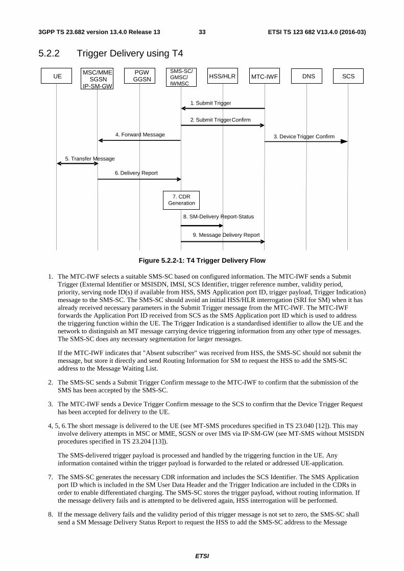
ETSI
ETSI TS 123 682 V13.4.0 (2016-03)333GPP TS 23.682 version 13.4.0 Release 13
5.2.2 Trigger Delivery using T4
UE MSC/MME
SGSN IP-SM-GW
PGW GGSN HSS/HLR SCS DNS
4 . Forward Message
5 . Transfer Message
6 . Delivery Report
SMS-SC/ GMSC/ IWMSC
MTC-IWF
1 . Submit Trigger
2 . Submit Trigger Confirm
9. Message Delivery Report
3 . Device Trigger Confirm
7 . CDR Generation
8. SM-Delivery Report-Status
Figure 5.2.2-1: T4 Trigger Delivery Flow
1. The MTC-IWF selects a suitable SMS-SC based on configured information. The MTC-IWF sends a Submit Trigger (External Identifier or MSISDN, IMSI, SCS Identifier, trigger reference number, validity period, priority, serving node ID(s) if available from HSS, SMS Application port ID, trigger payload, Trigger Indication) message to the SMS-SC. The SMS-SC should avoid an initial HSS/HLR interrogation (SRI for SM) when it has already received necessary parameters in the Submit Trigger message from the MTC-IWF. The MTC-IWF forwards the Application Port ID received from SCS as the SMS Application port ID which is used to address the triggering function within the UE. The Trigger Indication is a standardised identifier to allow the UE and the network to distinguish an MT message carrying device triggering information from any other type of messages. The SMS-SC does any necessary segmentation for larger messages.
If the MTC-IWF indicates that "Absent subscriber" was received from HSS, the SMS-SC should not submit the message, but store it directly and send Routing Information for SM to request the HSS to add the SMS-SC address to the Message Waiting List.
2. The SMS-SC sends a Submit Trigger Confirm message to the MTC-IWF to confirm that the submission of the SMS has been accepted by the SMS-SC.
3. The MTC-IWF sends a Device Trigger Confirm message to the SCS to confirm that the Device Trigger Request has been accepted for delivery to the UE.
4, 5, 6. The short message is delivered to the UE (see MT-SMS procedures specified in TS 23.040 [12]). This may involve delivery attempts in MSC or MME, SGSN or over IMS via IP-SM-GW (see MT-SMS without MSISDN procedures specified in TS 23.204 [13]).
The SMS-delivered trigger payload is processed and handled by the triggering function in the UE. Any information contained within the trigger payload is forwarded to the related or addressed UE-application.
7. The SMS-SC generates the necessary CDR information and includes the SCS Identifier. The SMS Application port ID which is included in the SM User Data Header and the Trigger Indication are included in the CDRs in order to enable differentiated charging. The SMS-SC stores the trigger payload, without routing information. If the message delivery fails and is attempted to be delivered again, HSS interrogation will be performed.
8. If the message delivery fails and the validity period of this trigger message is not set to zero, the SMS-SC shall send a SM Message Delivery Status Report to request the HSS to add the SMS-SC address to the Message
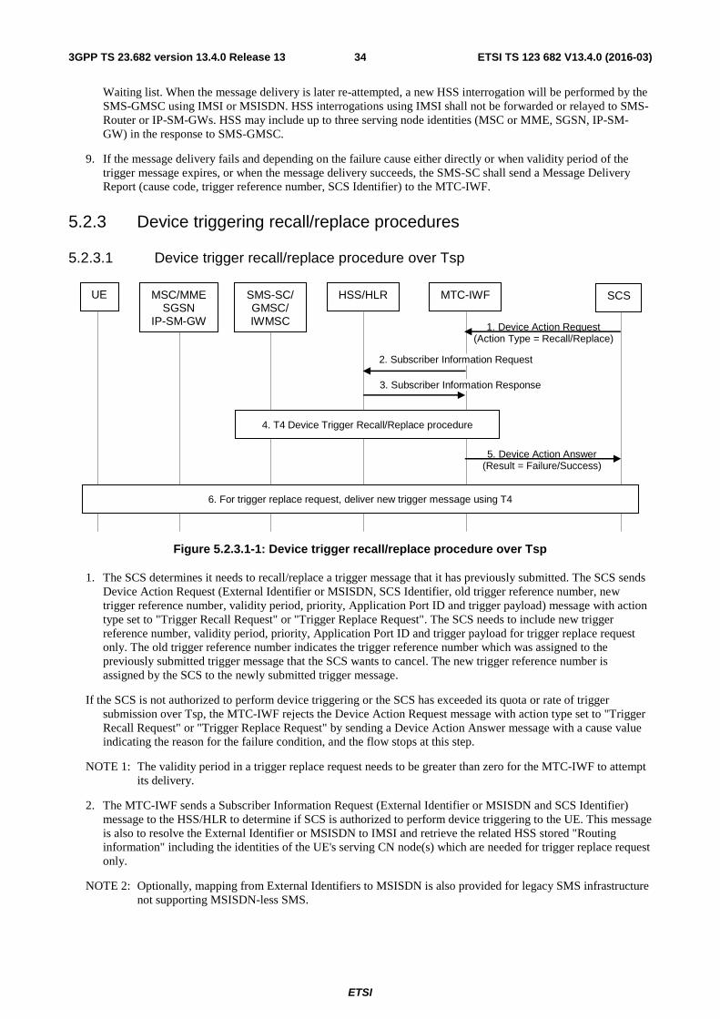
ETSI
ETSI TS 123 682 V13.4.0 (2016-03)343GPP TS 23.682 version 13.4.0 Release 13
Waiting list. When the message delivery is later re-attempted, a new HSS interrogation will be performed by the SMS-GMSC using IMSI or MSISDN. HSS interrogations using IMSI shall not be forwarded or relayed to SMS-Router or IP-SM-GWs. HSS may include up to three serving node identities (MSC or MME, SGSN, IP-SM-GW) in the response to SMS-GMSC.
9. If the message delivery fails and depending on the failure cause either directly or when validity period of the trigger message expires, or when the message delivery succeeds, the SMS-SC shall send a Message Delivery Report (cause code, trigger reference number, SCS Identifier) to the MTC-IWF.
5.2.3 Device triggering recall/replace procedures
5.2.3.1 Device trigger recall/replace procedure over Tsp
1. Device Action Request (Action Type = Recall/Replace)
5. Device Action Answer (Result = Failure/Success)
UE MSC/MME SGSN
IP-SM-GW
SCS
SMS-SC/ GMSC/ IWMSC
MTC-IWF
HSS/HLR
4. T4 Device Trigger Recall/Replace procedure
2. Subscriber Information Request
3. Subscriber Information Response
6. For trigger replace request, deliver new trigger message using T4
Figure 5.2.3.1-1: Device trigger recall/replace procedure over Tsp
1. The SCS determines it needs to recall/replace a trigger message that it has previously submitted. The SCS sends Device Action Request (External Identifier or MSISDN, SCS Identifier, old trigger reference number, new trigger reference number, validity period, priority, Application Port ID and trigger payload) message with action type set to "Trigger Recall Request" or "Trigger Replace Request". The SCS needs to include new trigger reference number, validity period, priority, Application Port ID and trigger payload for trigger replace request only. The old trigger reference number indicates the trigger reference number which was assigned to the previously submitted trigger message that the SCS wants to cancel. The new trigger reference number is assigned by the SCS to the newly submitted trigger message.
If the SCS is not authorized to perform device triggering or the SCS has exceeded its quota or rate of trigger submission over Tsp, the MTC-IWF rejects the Device Action Request message with action type set to "Trigger Recall Request" or "Trigger Replace Request" by sending a Device Action Answer message with a cause value indicating the reason for the failure condition, and the flow stops at this step.
NOTE 1: The validity period in a trigger replace request needs to be greater than zero for the MTC-IWF to attempt its delivery.
2. The MTC-IWF sends a Subscriber Information Request (External Identifier or MSISDN and SCS Identifier) message to the HSS/HLR to determine if SCS is authorized to perform device triggering to the UE. This message is also to resolve the External Identifier or MSISDN to IMSI and retrieve the related HSS stored "Routing information" including the identities of the UE's serving CN node(s) which are needed for trigger replace request only.
NOTE 2: Optionally, mapping from External Identifiers to MSISDN is also provided for legacy SMS infrastructure not supporting MSISDN-less SMS.
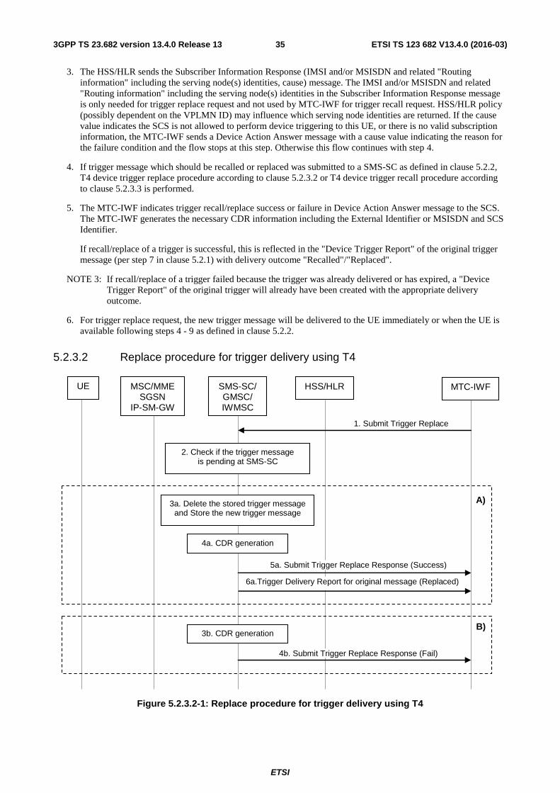
ETSI
ETSI TS 123 682 V13.4.0 (2016-03)353GPP TS 23.682 version 13.4.0 Release 13
3. The HSS/HLR sends the Subscriber Information Response (IMSI and/or MSISDN and related "Routing information" including the serving node(s) identities, cause) message. The IMSI and/or MSISDN and related "Routing information" including the serving node(s) identities in the Subscriber Information Response message is only needed for trigger replace request and not used by MTC-IWF for trigger recall request. HSS/HLR policy (possibly dependent on the VPLMN ID) may influence which serving node identities are returned. If the cause value indicates the SCS is not allowed to perform device triggering to this UE, or there is no valid subscription information, the MTC-IWF sends a Device Action Answer message with a cause value indicating the reason for the failure condition and the flow stops at this step. Otherwise this flow continues with step 4.
4. If trigger message which should be recalled or replaced was submitted to a SMS-SC as defined in clause 5.2.2, T4 device trigger replace procedure according to clause 5.2.3.2 or T4 device trigger recall procedure according to clause 5.2.3.3 is performed.
5. The MTC-IWF indicates trigger recall/replace success or failure in Device Action Answer message to the SCS. The MTC-IWF generates the necessary CDR information including the External Identifier or MSISDN and SCS Identifier.
If recall/replace of a trigger is successful, this is reflected in the "Device Trigger Report" of the original trigger message (per step 7 in clause 5.2.1) with delivery outcome "Recalled"/"Replaced".
NOTE 3: If recall/replace of a trigger failed because the trigger was already delivered or has expired, a "Device Trigger Report" of the original trigger will already have been created with the appropriate delivery outcome.
6. For trigger replace request, the new trigger message will be delivered to the UE immediately or when the UE is available following steps 4 - 9 as defined in clause 5.2.2.
5.2.3.2 Replace procedure for trigger delivery using T4
1. Submit Trigger Replace
UE MSC/MME SGSN
IP-SM-GW
MTC-IWF
SMS-SC/ GMSC/ IWMSC
HSS/HLR
3a. Delete the stored trigger message and Store the new trigger message
5a. Submit Trigger Replace Response (Success)
2. Check if the trigger message is pending at SMS-SC
A)
4a. CDR generation
6a.Trigger Delivery Report for original message (Replaced)
B)3b. CDR generation
4b. Submit Trigger Replace Response (Fail)
Figure 5.2.3.2-1: Replace procedure for trigger delivery using T4
ETSI
ETSI TS 123 682 V13.4.0 (2016-03)363GPP TS 23.682 version 13.4.0 Release 13
1. Based on the Action type in Device Action Request message, the MTC-IWF sends a Submit Trigger Replace (External Identifier or MSISDN, IMSI, SCS Identifier, old trigger reference number, new trigger reference number, validity period, priority, serving node ID(s) if available from HSS, SMS Application port ID, trigger payload, Trigger Indication) message to the SMS-SC. The MTC-IWF selects the SMS-SC to which the old trigger message was submitted, e.g. based on configured information.
2. The SMS-SC determines whether the trigger message identified by the External Identifier or MSISDN, SCS Identifier, and old trigger reference number in the received Submit Trigger Replace message, is pending at SMS-SC.
A) If the trigger message is pending at SMS-SC, steps 3a - 6a are performed.
3a. The SMS-SC deletes the stored trigger message and stores the new trigger message to deliver it when the UE is available.
4a. The SMS-SC generates the necessary CDR information and includes the SCS Identifier. The SMS Application port ID which is included in the SM User Data Header and the Trigger Indication are included in the CDRs in order to enable differentiated charging.
5a. The SMS-SC sends a Submit Trigger Replace Response message to the MTC-IWF to inform that the previously submitted trigger message has been successfully replaced by the new one in the SMS-SC.
6a. The SMS-SC sends a Trigger Delivery Report for the original trigger message indicating that this message has been replaced.
NOTE: Step 5a and step 6a are combined in single message in Stage 3.
B) If the trigger message is not pending at SMS-SC, steps 3b - 4b are performed. In this case, the SMS-SC treats the new trigger message as a trigger message that it has to deliver to the UE.
3b. The SMS-SC generates the necessary CDR information and includes the SCS Identifier. The SMS Application port ID which is included in the SM User Data Header and the Trigger Indication are included in the CDRs in order to enable differentiated charging.
4b. The SMS-SC sends a Submit Trigger Replace Response message to the MTC-IWF to inform that the replace request failed and the SMS-SC shall deliver the new trigger message.
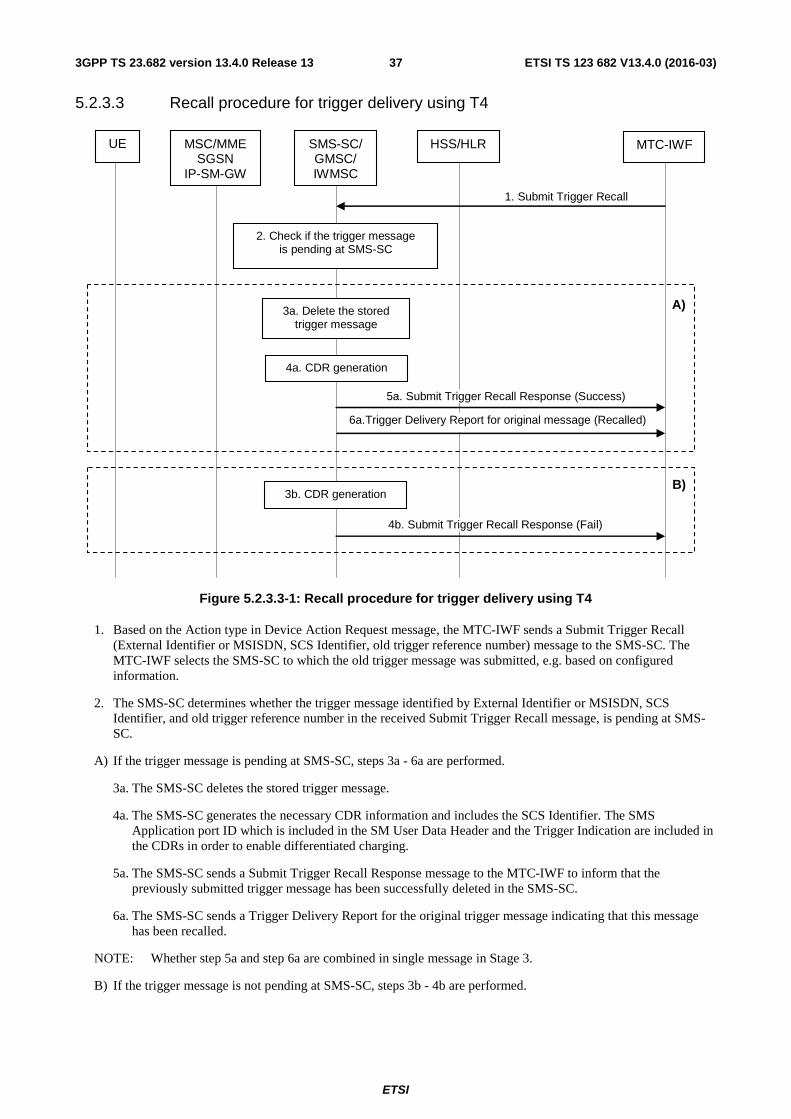
ETSI
ETSI TS 123 682 V13.4.0 (2016-03)373GPP TS 23.682 version 13.4.0 Release 13
5.2.3.3 Recall procedure for trigger delivery using T4
1. Submit Trigger Recall
UE MSC/MME SGSN
IP-SM-GW
MTC-IWF
SMS-SC/ GMSC/ IWMSC
HSS/HLR
3a. Delete the stored trigger message
5a. Submit Trigger Recall Response (Success)
2. Check if the trigger message is pending at SMS-SC
A)
4a. CDR generation
6a.Trigger Delivery Report for original message (Recalled)
B)3b. CDR generation
4b. Submit Trigger Recall Response (Fail)
Figure 5.2.3.3-1: Recall procedure for trigger delivery using T4
1. Based on the Action type in Device Action Request message, the MTC-IWF sends a Submit Trigger Recall (External Identifier or MSISDN, SCS Identifier, old trigger reference number) message to the SMS-SC. The MTC-IWF selects the SMS-SC to which the old trigger message was submitted, e.g. based on configured information.
2. The SMS-SC determines whether the trigger message identified by External Identifier or MSISDN, SCS Identifier, and old trigger reference number in the received Submit Trigger Recall message, is pending at SMS-SC.
A) If the trigger message is pending at SMS-SC, steps 3a - 6a are performed.
3a. The SMS-SC deletes the stored trigger message.
4a. The SMS-SC generates the necessary CDR information and includes the SCS Identifier. The SMS Application port ID which is included in the SM User Data Header and the Trigger Indication are included in the CDRs in order to enable differentiated charging.
5a. The SMS-SC sends a Submit Trigger Recall Response message to the MTC-IWF to inform that the previously submitted trigger message has been successfully deleted in the SMS-SC.
6a. The SMS-SC sends a Trigger Delivery Report for the original trigger message indicating that this message has been recalled.
NOTE: Whether step 5a and step 6a are combined in single message in Stage 3.
B) If the trigger message is not pending at SMS-SC, steps 3b - 4b are performed.
ETSI
ETSI TS 123 682 V13.4.0 (2016-03)383GPP TS 23.682 version 13.4.0 Release 13
3b. The SMS-SC generates the necessary CDR information and includes the SCS Identifier. The SMS Application port ID which is included in the SM User Data Header and the Trigger Indication are included in the CDRs in order to enable differentiated charging.
4b. The SMS-SC sends a Submit Trigger Recall Response message to the MTC-IWF with a cause value indicating that the recall request failed.
5.3 Information Storage This clause describes the context information that is stored in the different nodes for MTC device trigger procedure.
5.3.1 Trigger Information in SMS-SC (Triggering with T4)
This table includes information that needs to be stored in SMS-SC for triggering with T4.
Table 5.3.1-1: SMS-SC trigger information
Field Description External Identifier/MSISDN It is used to identify the corresponding External Identifiers in the delivery report.
This can be also the MSISDN if used. IMSI It is used to indicate the UE used for MTC that is required to be triggered. Trigger reference number This is to co-relate the trigger request with trigger response. SCS ID It is used to allow the SMS SC to send the trigger response back to the
appropriate SCS. Trigger payload The SMSC will store the Trigger payload until it receives the delivery
confirmation. Routing Information for SMS The identities of the serving node(s). Priority It is used to indicate the priority of trigger request. Validity period To indicate the time period for which the trigger request is valid. SMS Application Port ID It is used to route the short message to the triggering function in the UE.
NOTE 1: The Trigger Payload is stored as user data in SMS-SC.
NOTE 2: Priority, Validity period and SMS Application Port ID are included in the Trigger payload.
5.4 Security Procedures
5.4.0 General
The security procedures are specified in TS 33.187 [25].
5.4.1 Void
5.4.2 Void
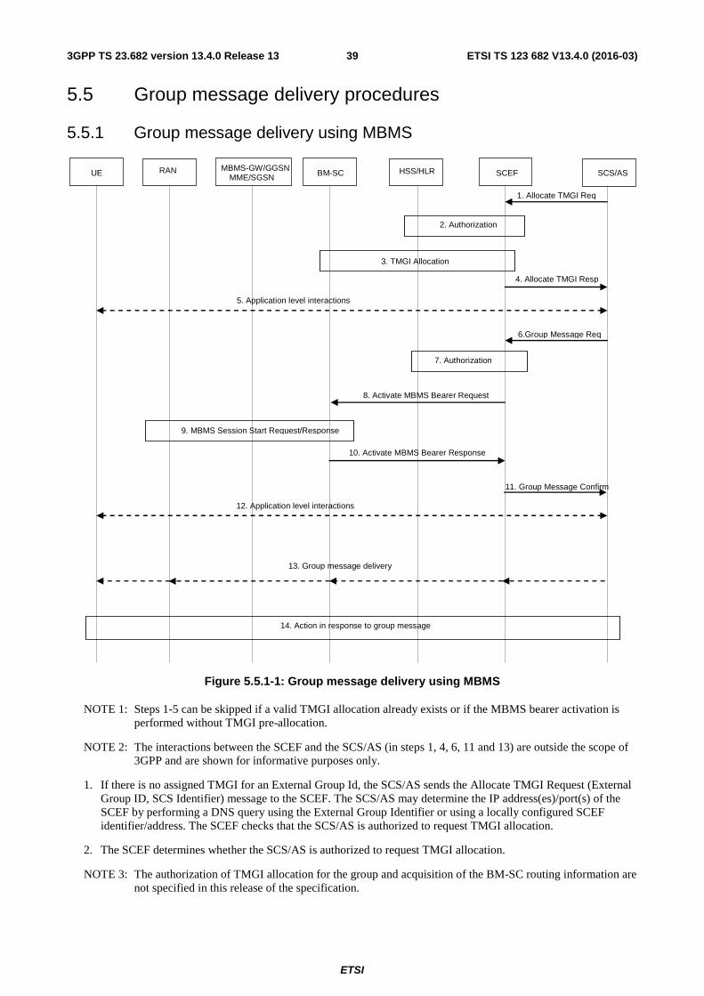
ETSI
ETSI TS 123 682 V13.4.0 (2016-03)393GPP TS 23.682 version 13.4.0 Release 13
5.5 Group message delivery procedures
5.5.1 Group message delivery using MBMS
UE RAN MBMS-GW/GGSN
MME/SGSN SCS/ASBM-SC SCEF
1. Allocate TMGI Req
9. MBMS Session Start Request/Response
14. Action in response to group message
2. Authorization
3. TMGI Allocation
4. Allocate TMGI Resp
12. Application level interactions
6.Group Message Req
7. Authorization
8. Activate MBMS Bearer Request
10. Activate MBMS Bearer Response
11. Group Message Confirm
13. Group message delivery
HSS/HLR
5. Application level interactions
Figure 5.5.1-1: Group message delivery using MBMS
NOTE 1: Steps 1-5 can be skipped if a valid TMGI allocation already exists or if the MBMS bearer activation is performed without TMGI pre-allocation.
NOTE 2: The interactions between the SCEF and the SCS/AS (in steps 1, 4, 6, 11 and 13) are outside the scope of 3GPP and are shown for informative purposes only.
1. If there is no assigned TMGI for an External Group Id, the SCS/AS sends the Allocate TMGI Request (External Group ID, SCS Identifier) message to the SCEF. The SCS/AS may determine the IP address(es)/port(s) of the SCEF by performing a DNS query using the External Group Identifier or using a locally configured SCEF identifier/address. The SCEF checks that the SCS/AS is authorized to request TMGI allocation.
2. The SCEF determines whether the SCS/AS is authorized to request TMGI allocation.
NOTE 3: The authorization of TMGI allocation for the group and acquisition of the BM-SC routing information are not specified in this release of the specification.
ETSI
ETSI TS 123 682 V13.4.0 (2016-03)403GPP TS 23.682 version 13.4.0 Release 13
3. The SCEF initiates TMGI allocation by the BM-SC (see TMGI Allocation Procedure specified in TS 23.468 [30]).
4. The SCEF sends the received TMGI and expiration time information to the SCS/AS.
NOTE 4: The SCEF may cache the serving BM-SC Identity information and mapping between External Group ID and TMGI.
5. Application level interactions may be applied for the devices of specific group to retrieve the related MBMS service information, e.g. TMGI, start time. Application level interactions between the UE and the SCS/AS are out of scope of this specification.
6. The SCS/AS sends the Group Message Request (External Group Identifier, SCS Identifier, location/area information, RAT(s) information, TMGI, start time) message to the SCEF. The location/area information indicated by the SCS/AS may be the geographic area information.
7. The SCEF checks that the SCS/AS is authorised to send a group message request. If this check fails the SCEF sends a Group Message Confirm message with a cause value indicating the reason for the failure condition and the flow stops at this step. In this case, the SCS/AS may subsequently release the TMGI allocated at step 3 by requesting an explicit de-allocation, or may rely on the expiration timer.
NOTE 5: Authorization of Group Message delivery using MBMS towards a specific group is not specified in this release of the specification.
8. The SCEF sends an Activate MBMS Bearer Request (MBMS broadcast area, TMGI, QoS, start time) message to the BM-SC (see TS 23.468 [30]).
NOTE 6: The SCEF maps between location/area information provided by the SCS/AS and the MBMS broadcast area for the distribution of the content to the group based on configuration in the operator domain. The SCEF needs to be aware that the selected MBMS broadcast area may result in broadcast of the content over an area larger than the area that may be indicated by SCS/AS.
9. BM-SC performs the Session Start procedure (see MBMS Session Start procedure specified in TS 23.246 [29]).
10. The BM-SC sends an Activate MBMS Bearer Response to the SCEF (see TS 23.468 [30]).
11. The SCEF sends a Group Message Confirm (TMGI (optional), SCEF IP addresses/port) message to the SCS/AS to indicate whether the Request has been accepted for delivery to the group.
12. Application level interactions may be applied for the devices of specific group to retrieve the related MBMS service information, e.g. TMGI, start time. Application level interactions between the UE and the SCS/AS are out of scope of this specification.
13. At or after the requested start time, but before the expiration time, the SCS/AS transfers the content to be delivered to the group to the SCEF using the IP address and port received at step 11. SCEF delivers the contents to BM-SC via MB2-U, using the IP address and port received at step 9. The BM-SC transfers the corresponding content to UEs. To avoid that potential responses to the broadcast message by high numbers of devices are sent at almost the same time, the SCS/AS makes sure the UEs are provided with a response time window if it expects the UEs to respond to the delivered content.
NOTE 7: Subsequent to this step, it is up to the SCS/AS if the MBMS bearers will be kept active and allocated and for how long. The mechanisms defined in TS 23.468 [30] can be used by the SCEF to release the MBMS resources.
14. In response to the received content, the UE may initiate immediate or later communication with the SCS/AS.
NOTE 8: The UE application ensures distribution of any responses within the response time window.
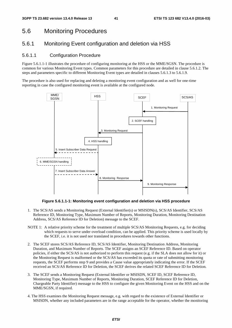
ETSI
ETSI TS 123 682 V13.4.0 (2016-03)413GPP TS 23.682 version 13.4.0 Release 13
5.6 Monitoring Procedures
5.6.1 Monitoring Event configuration and deletion via HSS
5.6.1.1 Configuration Procedure
Figure 5.6.1.1-1 illustrates the procedure of configuring monitoring at the HSS or the MME/SGSN. The procedure is common for various Monitoring Event types. Common parameters for this procedure are detailed in clause 5.6.1.2. The steps and parameters specific to different Monitoring Event types are detailed in clauses 5.6.1.3 to 5.6.1.9.
The procedure is also used for replacing and deleting a monitoring event configuration and as well for one-time reporting in case the configured monitoring event is available at the configured node.
SCS/AS HSS MME/
SGSN SCEF
1. Monitoring Request
9. Monitoring Response
2. SCEF handling
3. Monitoring Request
8. Monitoring Response
5. Insert Subscriber Data Request
7. Insert Subscriber Data Answer
4. HSS handling
6. MME/SGSN handling
Figure 5.6.1.1-1: Monitoring event configuration and deletion via HSS procedure
1. The SCS/AS sends a Monitoring Request (External Identifier(s) or MSISDN(s), SCS/AS Identifier, SCS/AS Reference ID, Monitoring Type, Maximum Number of Reports, Monitoring Duration, Monitoring Destination Address, SCS/AS Reference ID for Deletion) message to the SCEF.
NOTE 1: A relative priority scheme for the treatment of multiple SCS/AS Monitoring Requests, e.g. for deciding which requests to serve under overload condition, can be applied. This priority scheme is used locally by the SCEF, i.e. it is not used nor translated in procedures towards other functions.
2. The SCEF stores SCS/AS Reference ID, SCS/AS Identifier, Monitoring Destination Address, Monitoring Duration, and Maximum Number of Reports. The SCEF assigns an SCEF Reference ID. Based on operator policies, if either the SCS/AS is not authorized to perform this request (e.g. if the SLA does not allow for it) or the Monitoring Request is malformed or the SCS/AS has exceeded its quota or rate of submitting monitoring requests, the SCEF performs step 9 and provides a Cause value appropriately indicating the error. If the SCEF received an SCS/AS Reference ID for Deletion, the SCEF derives the related SCEF Reference ID for Deletion.
3. The SCEF sends a Monitoring Request (External Identifier or MSISDN, SCEF ID, SCEF Reference ID, Monitoring Type, Maximum Number of Reports, Monitoring Duration, SCEF Reference ID for Deletion, Chargeable Party Identifier) message to the HSS to configure the given Monitoring Event on the HSS and on the MME/SGSN, if required.
4. The HSS examines the Monitoring Request message, e.g. with regard to the existence of External Identifier or MSISDN, whether any included parameters are in the range acceptable for the operator, whether the monitoring
ETSI
ETSI TS 123 682 V13.4.0 (2016-03)423GPP TS 23.682 version 13.4.0 Release 13
event(s) is supported by the serving MME/SGSN, or whether the monitoring event that shall be deleted is valid. The HSS optionally authorizes the chargeable party identified by Chargeable Party Identifier. If this check fails the HSS follows step 8 and provides a Cause value indicating the reason for the failure condition to the SCEF.
NOTE 2: The details of the chargeable party authorization are outside the scope of this specifications.
The HSS stores the SCEF Reference ID, the SCEF ID, Maximum Number of Reports, Monitoring Duration and the SCEF Reference ID for Deletion as provided by the SCEF.
5. If required by the specific Monitoring Type and when Monitoring Event(s) is supported by the serving MME/SGSN, the HSS sends an Insert Subscriber Data Request (Monitoring Type, SCEF ID, SCEF Reference ID, Maximum Number of Reports, Monitoring Duration, SCEF Reference ID for Deletion, Chargeable Party Identifier) message to the MME/SGSN.
6. If the MME/SGSN is configured to use an IWK-SCEF for the PLMN of the SCEF then clause 5.6.6 applies. Otherwise, the MME/SGSN verifies the request, e.g. if the Monitoring Type is covered by a roaming agreement when the request is from another PLMN or whether it serves the SCEF Reference ID for Deletion and can delete it. If this check fails the MME/SGSN follows step 7 and provides a Cause value indicating the reason for the failure condition to the SCEF. Based on operator policies, the MME/SGSN may also reject the request due to other reasons (e.g. overload or HSS has exceeded its quota or rate of submitting monitoring requests defined by an SLA).
The MME/SGSN stores the received parameters and starts to watch for the indicated Monitoring Event unless it is a One-time request and the Monitoring Event is available to the MME/SGSN at the time of sending Insert Subscriber Data Answer. The MME/SGSN deletes the monitoring configuration identified by the SCEF Reference ID for Deletion, if provided.
NOTE 3: The MME/SGSN will transfer the parameters stored for every monitoring task as part of its context information during an MME/SGSN change. If the UE detaches from the network, the HSS will receive the remaining number of reports in the Maximum Number of Reports parameter.
7. If the monitoring configuration is successful, the MME/SGSN sends an Insert Subscriber Data Answer (Cause) message to the HSS. If the requested Monitoring Event is available to the MME/SGSN at the time of sending Insert Subscriber Data Answer, then the MME/SGSN includes the Monitoring Event Report in the Insert Subscriber Data Answer message.
8. The HSS sends a Monitoring Response (SCEF Reference ID, Cause) message to the SCEF to acknowledge acceptance of the Monitoring Request and the deletion of the identified monitoring event configuration, if it was requested. The HSS deletes the monitoring event configuration identified by the SCEF Reference ID, if it was requested. If the requested Monitoring Event is available to the HSS at the time of sending Monitoring Response message or was received from the MME/SGSN in step 7, then the HSS includes a Monitoring Event Report in the Monitoring Response message.
If it is a One-time request and the Insert Subscriber Data Answer includes a Monitoring Event Report, the HSS deletes the associated Monitoring Event configuration.
In the case of UE mobility, the HSS determines whether the new MME/SGSN supports requested Monitoring Event(s).
9. The SCEF sends a Monitoring Response (SCS/AS Reference ID, Cause) message to the SCS/AS to acknowledge acceptance of the Monitoring Request and the deletion of the identified monitoring event configuration, if it was requested. If the SCEF received a Monitoring Event Report then it includes the Monitoring Event Report in the Monitoring Response message. If it is a One-time request and the Monitoring Response includes a Monitoring Event Report, the SCEF deletes the associated Monitoring Event configuration.
If the HSS detects that the current serving MME/SGSN can not support a requested Monitoring Event (e.g. after a UE mobility event), the HSS performs the procedures in either (a) or (b) below. The criteria used to determine the choice of (a) or (b) is considered out of scope of the specifications.
(a) Notify the SCEF that the configured Monitoring Event is cancelled, and:
- shall delete the Monitoring Event, if the Monitoring Event is configured in the HSS, and
ETSI
ETSI TS 123 682 V13.4.0 (2016-03)433GPP TS 23.682 version 13.4.0 Release 13
- may include a "retry after" value to inform the SCEF of when (re)-configuration of the Monitoring Event(s) can be attempted again. The "retry after" value can be configured in the HSS by the operator. The SCEF can further notify the SCS/AS and provide the "retry after" value to the SCS/AS.
(b) Notify the SCEF that the configured Monitoring Event is considered to be suspended. The SCEF interprets this to mean that the network will temporarily be unable to serve the configured Monitoring Event. In this case:
- When the MME/SGSN for the UE changes (eg due to UE mobility), and the new MME/SGSN supports the suspended Monitoring Event, the HSS shall configure the new MME/SGSN with the Monitoring Event and notify the SCEF of resumption of the suspended Monitoring Event;
- If the criteria for Continuous Reporting expire while the Monitoring Event is suspended, the HSS and the SCEF shall independently delete the Monitoring Event.
5.6.1.2 Common Parameters of the Configuration Procedure
This clause describes the common parameters related to the monitoring event configuration procedure.
SCS/AS Reference ID is a parameter created by the SCS/AS to refer to a specific transaction initiated by the SCS/AS towards the SCEF. SCS/AS Reference ID is stored by the SCEF.
SCEF Reference ID is a parameter created by the SCEF to associate a Monitoring Event report or a deletion of a Monitoring Event to a specific Monitoring Request and the associated context information within the SCEF. SCEF Reference ID is stored by HSS, MME or SGSN.
NOTE 1: An SCEF may aggregate Monitoring Event configuration requests for the same External identifier/MSISDN from different SCS/AS instances.
SCEF ID indicates the SCEF to which the Monitoring Indication message has to be sent to by the HSS, MME or SGSN. SCEF ID is stored by the HSS, MME or SGSN.
Monitoring Type identifies the specific Monitoring Event being requested.
Maximum Number of Reports is an optional parameter that indicates the maximum number of event reports to be generated by the HSS, MME, or SGSN until the associated monitoring event is considered to expire. A value of one implies a single event report is to be generated which makes it equivalent to a One-time Monitoring Request.
Monitoring Duration is an optional parameter that indicates the absolute time at which the related monitoring event request is considered to expire.
Inclusion of either Maximum Number of Reports (with a value higher than one) or Monitoring Duration makes the Monitoring Request a Continuous Monitoring Request. For a Continuous Monitoring Request, a single Monitoring Request may generate more than one Monitoring Indication message. Support of continuous monitoring is optional.
Absence of both Maximum Number of Reports and Monitoring Duration makes the Monitoring Request a One-time Monitoring Request. For One-time Monitoring Requests, a single Monitoring Request generates only one Monitoring Report.
If for a given Monitoring Event both Maximum Number of Reports and Monitoring Duration are included then the monitoring request is considered to expire as soon as one of the conditions is met.
Monitoring Destination Address is an optional parameter included by the SCS/AS to indicate that the Monitoring Indication(s) are to be delivered to an address different from the address of the requesting SCS/AS. Absence of this parameter implies that Monitoring Indication(s) are to be sent to the SCS/AS that originated the Monitoring Request.
SCS/AS Reference ID for Deletion identifies the monitoring event configuration that shall be deleted before applying the requested monitoring event configuration.
SCEF Reference ID for Deletion identifies the monitoring event configuration that shall be deleted before applying the requested monitoring event configuration.
Chargeable Party Identifier is an optional parameter included by the SCEF. It identifies the entity towards which accounting/charging functionality is performed by the involved 3GPP network elements.
ETSI
ETSI TS 123 682 V13.4.0 (2016-03)443GPP TS 23.682 version 13.4.0 Release 13
5.6.1.3 Specific Parameters for Monitoring Event: Loss of connectivity
Loss of connectivity indicates when the 3GPP network detects that the UE is no longer reachable for either signalling or user plane communication. Such condition is identified when the mobile reachability timer expires in the MME or SGSN (see TS 23.401 [7], TS 23.060 [6]). The SCS/AS may provide a Maximum Detection Time, which indicates the maximum period of time without any communication with the UE after which the SCS/AS is to be informed that the UE is considered to be unreachable.
NOTE 1: As the Maximum Detection Time of loss of connectivity determines the order of magnitude of the Periodic Update timer, the network should ensure that this Maximum Detection Time and thereby the periodic TAU/RAU timers for the UE remain above lower bound values both for preserving the battery of the UE and for managing the signalling load of the network. So for UEs with battery constraints, it should not be a small time (e.g. on the order of only a few minutes). Even for UEs without battery constraints, trying to fulfil a Maximum Detection Time of loss of connectivity on the order of a few minutes can only apply to a limited number of UEs due to the cost of signalling induced by this feature.
NOTE 2: The Maximum Detection Time of loss of connectivity is on the order of 1 minute to multiple hours.
1. The SCS/AS sets Monitoring Type to "Loss of Connectivity", and optionally adds Maximum Detection Time prior to sending Monitoring Request to the SCEF as in step 1 of clause 5.6.1.1.
2. The SCEF executes step 2 of clause 5.6.1.1.
3. The SCEF executes step 3 of clause 5.6.1.1.
4. The HSS executes step 4 of clause 5.6.1.1. In addition, it checks whether the Maximum Detection Time is within the range defined by operator policies, and, if acceptable then the HSS sets the subscribed periodic RAU/TAU timer using the value of Maximum Detection Time, if it is provided. If the Maximum Detection Time is not acceptable, the HSS rejects the request. If the subscribed periodic RAU/TAU Timer was previously set by a different Monitoring Request identified by a different SCEF Reference ID for the same UE then, depending on operator configuration, the HSS either performs step 8 to reject the Monitoring Request with an appropriate Cause or accepts the request. In case the HSS accepts the request, then it cancels the previously accepted Monitoring Request.
NOTE 3: Since the value of the mobile reachable timer is larger than the value of the periodic RAU/TAU timer (by four minutes as a default), the HSS may set the subscribed periodic RAU/TAU timer to a smaller value than the value of Maximum Detection Time.
5. The HSS executes step 5 of clause 5.6.1.1. In addition, the HSS includes the subscribed periodic RAU/TAU Timer (if modified).
6. The MME/SGSN executes step 6 of clause 5.6.1.1. If the MME/SGSN receives a subscribed periodic RAU/TAU timer value from the HSS, it allocates the subscribed value to the UE as the periodic TAU/RAU timer. The MME/SGSN starts watching for the expiration of the mobile reachable timer.
7-9. Steps 7-9 of clause 5.6.1.1 are executed.
5.6.1.4 Specific Parameters for Monitoring Event: UE reachability
UE reachability indicates when the UE becomes reachable for sending either SMS or downlink data to the UE, which is detected when the UE transitions to ECM_CONNECTED mode (for a UE using Power Saving Mode or extended idle mode DRX) or when the UE will become reachable for paging (for a UE using extended idle mode DRX). This monitoring event supports Reachabilty for SMS and Reachability for Data. Only a One-time Monitoring Request for Reachability for SMS is supported. The SCS/AS may include the following parameters in the Monitoring Event configuration request to the SCEF:
- Reachability Type indicating whether the request is for "Reachability for SMS", or "Reachability for Data", or both.
- Optionally, Maximum Latency indicating maximum delay acceptable for downlink data transfers. Maximum Latency is used for setting the periodic TAU/RAU timer for the UE as it sets the maximum period after which a UE has to connect to the network again and thereby becomes reachable. Determined by the operator, low values for Maximum Latency may deactivate PSM.
ETSI
ETSI TS 123 682 V13.4.0 (2016-03)453GPP TS 23.682 version 13.4.0 Release 13
- Optionally, Maximum Response Time indicating the time for which the UE stays reachable to allow the SCS/AS to reliably deliver the required downlink data. Maximum Response Time is used for setting the Active Time for the UE. When the UE uses extended idle mode DRX, the Maximum Response Time is used to determine how early this monitoring event should be reported to the SCS/AS before the next Paging Occasion occurs.
- Optionally, Suggested number of downlink packets indicating the number of packets that the Serving Gateway shall buffer in case the UE is not reachable.
NOTE 1: As the Maximum Latency determines the order of magnitude of the Periodic Update timer, the network should ensure that this Maximum Latency and thereby the periodic TAU/RAU timers for the UE remain above lower bound values both for preserving the battery of the UE and for managing the signalling load of the network. So for UEs with battery constraints, it should not be a small time (e.g. on the order of only a few minutes). Even for UEs without battery constraints, trying to fulfil a Maximum Latency on the order of a few minutes can only apply to a limited number of UEs due to the cost of signalling induced by this feature.
NOTE 2: The Maximum Latency is on the order of 1 minute to multiple hours.
1. The SCS/AS sets Monitoring Type to "UE Reachability", and includes Reachability Type, optionally Maximum Latency, and optionally Maximum Response Time prior to sending the Monitoring Request to the SCEF as in step 1 of clause 5.6.1.1.
2. The SCEF executes step 2 of clause 5.6.1.1. In addition, it checks whether the Maximum Latency and the Maximum Response Time are within the range defined by operator policies. If not, then depending on operator policies, the SCEF rejects the request by performing step 9 of 5.6.1.1 with an appropriate cause value.
3. When "Reachability for SMS" is requested, the SCEF subscribes with the HSS by executing step 3 of 5.6.1.1 to get notified when the HSS is notified that the UE is reachable. The HSS performs the UE Reachability Notification Request procedure for getting a UE Activity Notification as described in TS 23.401 [7].
When "Reachability for Data" is requested, the SCEF executes step 3 of 5.6.1.1. In addition, if provided, it includes Maximum Latency, and Maximum Response Time.
4. The HSS executes step 4 of clause 5.6.1.1. In addition, if acceptable, the HSS sets the subscribed periodic RAU/TAU timer to the value of Maximum Latency, if it is provided. If the requested timer value is not acceptable, the HSS rejects the request. If the subscribed periodic RAU/TAU timer was previously set by a different Monitoring Request identified by a different SCEF Reference ID for the same UE then, depending on operator configuration, the HSS either performs step 8 to reject the Monitoring Request with an appropriate Cause or accepts the request. In the case that the HSS accepts the request, then it cancels the previously accepted Monitoring Request.
5. The HSS executes step 5 of clause 5.6.1.1. In addition, the HSS includes the subscribed periodic RAU/TAU timer (if modified), Maximum Response Time (if provided).
6. The MME/SGSN executes step 6 of clause 5.6.1.1 and starts watching for the UE entering connected mode. At every subsequent TAU/RAU procedure, the MME/SGSN applies the subscribed periodic RAU/TAU timer.
7-9. Steps 7-9 of clause 5.6.1.1 are executed.
5.6.1.5 Specific Parameters for Monitoring Event: Location Reporting
This monitoring event allows the SCS/AS to request either the Current Location or the Last Known Location of a UE. The supported location accuracy is at either cell level (CGI/ECGI), eNodeB, TA/RA level. Only One-time Reporting is supported for the Last Known Location. One-time and Continuous Location Reporting are supported for the Current Location. For Continuous Location Reporting the serving node(s) sends a notification every time it becomes aware of a location change, with the granularity depending on the requested accuracy.
NOTE 1: Due to the potential increase in signalling load, it is recommended that a continuous monitoring of current location on cell level is only applied for a limited number of subscribers.
1. The SCS/AS sets Monitoring Type to "Location Reporting", and adds Location Type and optionally Accuracy prior to sending Monitoring Request to the SCEF as in step 1 of clause 5.6.1.1.
ETSI
ETSI TS 123 682 V13.4.0 (2016-03)463GPP TS 23.682 version 13.4.0 Release 13
Location Type indicates whether the request is for Current Location or Last Known Location. The Accuracy parameter indicates desired level of accuracy of the requested location information.
NOTE 2: Accuracy could be at cell level (CGI/ECGI), eNodeB, TA/RA level or other formats e.g. shapes (e.g. polygons, circles etc.) or civic addresses (e.g. streets, districts etc.) as referenced by OMA Presence API [32].
2. The SCEF executes step 2 of clause 5.6.1.1.
3. If Accuracy is included in step 1 then based on operator configuration the SCEF maps it to permissible granularity at cell level (CGI/ECGI), eNodeB level or TA/RA level. If Accuracy is not included in step 1, the SCEF sets the granularity based on operator configuration. The SCEF adds Location Type and Accuracy prior to sending the Monitoring Request to the HSS as in step 3 of clause 5.6.1.1.
4. The HSS executes step 4 of clause 5.6.1.1.
5. Depending on the Location Type the HSS sets the "Current Location Request" (see TS 29.272 [31]), and adds Accuracy prior to sending the Insert Subscriber Data Request to the MME/SGSN as in step 5 of clause 5.6.1.1.
6. The MME/SGSN executes step 6 of clause 5.6.1.1 and depending on the requested Accuracy invokes the appropriate procedures as defined in TS 23.401 [7] or 23.060 [6] for determining the location as requested. Unless it is a One-time request, the MME/SGSN starts watching for cell/RA/TA/eNodeB changes, depending on requested Accuracy.
7-9. Steps 7-9 of clause 5.6.1.1 are executed and include the report of the current or last known location, depending on what was requested. The SCEF maps eNodeB-ID/cell-ID/RAI/TAI to geo-location before reporting to the SCS/AS.
5.6.1.6 Specific Parameters for Monitoring Event: Change of IMSI-IMEI(SV) Association
Change of IMSI-IMEI(SV) indicates a change of the ME (IMEI(SV)) that uses a specific subscription (IMSI). It is based on the HSS being informed by the MME about the UE's IMEI(SV) according to the procedures defined in TS 23.401 [7]. The support of this Monitoring Event by the SGSN requires the support of the Automatic Device Detection (ADD) function/feature defined in TS 23.060 [6].
1. The SCS/AS sets Monitoring Type to "Change of IMSI-IMEI(SV) Association" , and adds Association Type prior to sending Monitoring Request to the SCEF as in step 1 of clause 5.6.1.1.
Association Type indicates whether change of IMEI or IMEISV to IMSI association shall be detected.
2. The SCEF executes step 2 of clause 5.6.1.1.
3. The SCEF adds Association Type prior to sending the Monitoring Request to the HSS as in step 3 of clause 5.6.1.1.
4. The HSS executes step 4 of clause 5.6.1.1.
5-7. Steps 5-7 of clause 5.6.1.1 shall not be executed for this Monitoring Event.
8-9. Steps 8-9 of clause 5.6.1.1 are executed.
5.6.1.7 Specific Parameters for Monitoring Event: Roaming Status
This monitoring event allows the SCS/AS to query the UE's current roaming status (the serving PLMN and/or whether the UE is in its HPLMN) and to get notified when that status changes. It is based on the HSS being informed of the UE's serving PLMN by the MME according to TS 23.401 [7] and by the SGSN according to TS 23.060 [6].
1. The SCS/AS sets Monitoring Type to "Roaming Status" prior to sending the Monitoring Request to the SCEF as in step 1 of clause 5.6.1.1. Optionally, it includes the "PLMN Information" parameter to request inclusion of the UE's Serving PLMN ID in the Monitoring Event Report.
2. The SCEF executes step 2 of clause 5.6.1.1.
ETSI
ETSI TS 123 682 V13.4.0 (2016-03)473GPP TS 23.682 version 13.4.0 Release 13
3. The SCEF includes "PLMN Information", if sent in step 1, prior to sending Monitoring Request to the HSS as in step 3 of clause 5.6.1.1.
4. The HSS executes step 4 of clause 5.6.1.1.
5-7. Steps 5-7 of clause 5.6.1.1 shall not be executed for this Monitoring Event.
8-9. Steps 8-9 of clause 5.6.1.1 are executed. The Monitoring Event Report for this event is sent in the Monitoring Response message. The Monitoring Event Report indicates whether the UE is presently roaming or not. If PLMN Information was requested in step 1, and the operator policies allow, then the HSS includes:
- the HPLMN PLMN-Id if the UE is in the HPLMN or
- the Visited PLMN-Id (see TS 29.272 [31]) if the UE is in the VPLMN.
5.6.1.8 Specific Parameters for Monitoring Event: Communication failure
This monitoring event allows the SCS/AS to be notified of communication failure events, identified by RAN/NAS Release Cause codes per TS 23.401 [7].
1. The SCS/AS sets Monitoring Type to "Communication Failure" prior to sending Monitoring Request to the SCEF as in step 1 of clause 5.6.1.1.
2. The SCEF executes step 2 of clause 5.6.1.1.
3. The SCEF executes step 3 of clause 5.6.1.1.
4. The HSS executes step 4 of clause 5.6.1.1.
5. The HSS executes step 5 of clause 5.6.1.1.
6. The MME/SGSN executes step 6 of clause 5.6.1.1 and starts watching for communication failure events.
7-9. Steps 7-9 of clause 5.6.1.1 are executed.
5.6.1.9 Specific Parameters for Monitoring Event: Availability after DDN Failure
This monitoring event allows the SCS/AS to be notified of availability of the UE after a DDN failure has occurred (see clause 5.7.1 Availability Notification after DDN Failure).
1. The SCS/AS sets Monitoring Type to "Availability after DDN Failure" prior to sending the Monitoring Request to the SCEF as in step 1 of clause 5.6.1.1.
2. The SCEF executes step 2 of clause 5.6.1.1.
3. The SCEF executes step 3 of clause 5.6.1.1 without adding Max Number of Reports, since the "Availability after DDN Failure" is an ongoing event that shall be deleted (see clause 5.6.1 for a description of Monitoring Event Deletion procedures) to cancel further reports.
4-5. Steps 4-5 of clause 5.6.1.1 are executed.
6. The MME/SGSN executes step 6 of clause 5.6.1.1 and starts watching for UE availability after DDN failure events.
7-9. Steps 7-9 of clause 5.6.1.1 are executed.
5.6.2 Monitoring Events configuration and deletion directly at the MME/SGSN
5.6.2.1 Configuration Procedure
Figure 5.6.2.1-1 illustrates the procedure of configuring monitoring at the MME/SGSN. The procedure is common for various monitoring event types. Common parameters for this procedure are detailed in clause 5.6.2.2. The steps specific to different Monitoring Event types are detailed in clause 5.6.2.3.
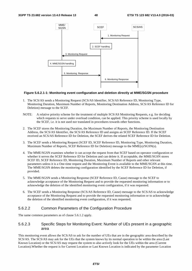
ETSI
ETSI TS 123 682 V13.4.0 (2016-03)483GPP TS 23.682 version 13.4.0 Release 13
SCS/AS
MME/ SGSN
SCEF
1. Monitoring Request
6 . Monitoring Response
2. SCEF handling
3. Monitoring Request
5. Monitoring Response
4. MME/SGSN handling
Figure 5.6.2.1-1: Monitoring event configuration and deletion directly at MME/SGSN procedure
1. The SCS/AS sends a Monitoring Request (SCS/AS Identifier, SCS/AS Reference ID, Monitoring Type, Monitoring Duration, Maximum Number of Reports, Monitoring Destination Address, SCS/AS Reference ID for Deletion) message to the SCEF.
NOTE: A relative priority scheme for the treatment of multiple SCS/AS Monitoring Requests, e.g. for deciding which requests to serve under overload condition, can be applied. This priority scheme is used locally by the SCEF, i.e. it is not used nor translated in procedures towards other functions.
2. The SCEF stores the Monitoring Duration, the Maximum Number of Reports, the Monitoring Destination Address, the SCS/AS Identifier, the SCS/AS Reference ID and assigns an SCEF Reference ID. If the SCEF received an SCS/AS Reference ID for Deletion, the SCEF derives the related SCEF Reference ID for Deletion.
3. The SCEF sends a Monitoring Request (SCEF ID, SCEF Reference ID, Monitoring Type, Monitoring Duration, Maximum Number of Reports, SCEF Reference ID for Deletion) message to the MME(s)/SGSN(s).
4. The MME/SGSN examines whether it can accept the request from that SCEF based on operator configuration or whether it serves the SCEF Reference ID for Deletion and can delete it. If acceptable, the MME/SGSN stores SCEF ID, SCEF Reference ID, Monitoring Duration, Maximum Number of Reports and other relevant parameters unless it is a One-time request and the Monitoring Event is available to the MME/SGSN at this time. The MME/SGSN deletes the monitoring configuration identified by the SCEF Reference ID for Deletion, if provided.
5. The MME/SGSN sends a Monitoring Response (SCEF Reference ID, Cause) message to the SCEF to acknowledge acceptance of the Monitoring Request and to provide the requested monitoring information or to acknowledge the deletion of the identified monitoring event configuration, if it was requested.
6. The SCEF sends a Monitoring Response (SCS/AS Reference ID, Cause) message to the SCS/AS to acknowledge acceptance of the Monitoring Request and to provide the requested monitoring information or to acknowledge the deletion of the identified monitoring event configuration, if it was requested.
5.6.2.2 Common Parameters of the Configuration Procedure
The same common parameters as of clause 5.6.1.2 apply.
5.6.2.3 Specific Steps for Monitoring Event: Number of UEs present in a geographic area
This monitoring event allows the SCS/AS to ask for the number of UEs that are in the geographic area described by the SCS/AS. The SCS/AS may ask for the UEs that the system knows by its normal operation to be within the area (Last Known Location) or the SCS/AS may request the system to also actively look for the UEs within the area (Current Location).Whether the request is for Current Location or Last Known Location is indicated by the parameter Location
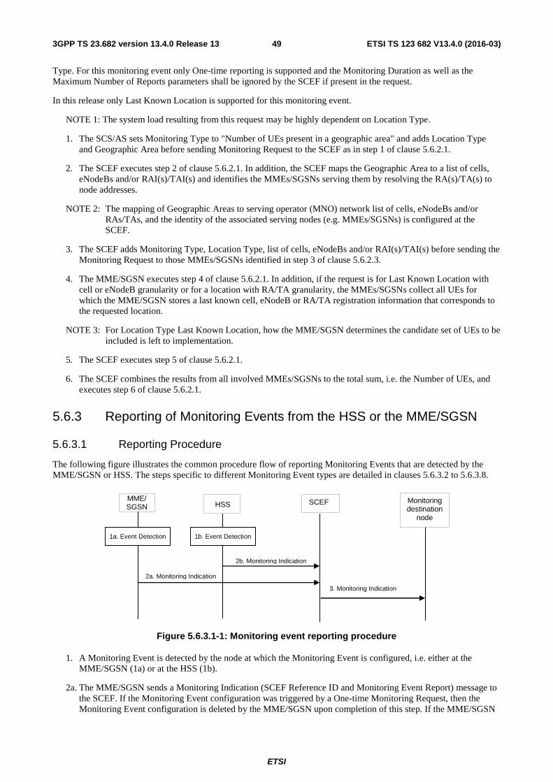
ETSI
ETSI TS 123 682 V13.4.0 (2016-03)493GPP TS 23.682 version 13.4.0 Release 13
Type. For this monitoring event only One-time reporting is supported and the Monitoring Duration as well as the Maximum Number of Reports parameters shall be ignored by the SCEF if present in the request.
In this release only Last Known Location is supported for this monitoring event.
NOTE 1: The system load resulting from this request may be highly dependent on Location Type.
1. The SCS/AS sets Monitoring Type to "Number of UEs present in a geographic area" and adds Location Type and Geographic Area before sending Monitoring Request to the SCEF as in step 1 of clause 5.6.2.1.
2. The SCEF executes step 2 of clause 5.6.2.1. In addition, the SCEF maps the Geographic Area to a list of cells, eNodeBs and/or RAI(s)/TAI(s) and identifies the MMEs/SGSNs serving them by resolving the RA(s)/TA(s) to node addresses.
NOTE 2: The mapping of Geographic Areas to serving operator (MNO) network list of cells, eNodeBs and/or RAs/TAs, and the identity of the associated serving nodes (e.g. MMEs/SGSNs) is configured at the SCEF.
3. The SCEF adds Monitoring Type, Location Type, list of cells, eNodeBs and/or RAI(s)/TAI(s) before sending the Monitoring Request to those MMEs/SGSNs identified in step 3 of clause 5.6.2.3.
4. The MME/SGSN executes step 4 of clause 5.6.2.1. In addition, if the request is for Last Known Location with cell or eNodeB granularity or for a location with RA/TA granularity, the MMEs/SGSNs collect all UEs for which the MME/SGSN stores a last known cell, eNodeB or RA/TA registration information that corresponds to the requested location.
NOTE 3: For Location Type Last Known Location, how the MME/SGSN determines the candidate set of UEs to be included is left to implementation.
5. The SCEF executes step 5 of clause 5.6.2.1.
6. The SCEF combines the results from all involved MMEs/SGSNs to the total sum, i.e. the Number of UEs, and executes step 6 of clause 5.6.2.1.
5.6.3 Reporting of Monitoring Events from the HSS or the MME/SGSN
5.6.3.1 Reporting Procedure
The following figure illustrates the common procedure flow of reporting Monitoring Events that are detected by the MME/SGSN or HSS. The steps specific to different Monitoring Event types are detailed in clauses 5.6.3.2 to 5.6.3.8.
Monitoring destination
node
HSS
1a. Event Detection
2b. Monitoring Indication
3. Monitoring Indication
MME/ SGSN
2a. Monitoring Indication
SCEF
1b. Event Detection
Figure 5.6.3.1-1: Monitoring event reporting procedure
1. A Monitoring Event is detected by the node at which the Monitoring Event is configured, i.e. either at the MME/SGSN (1a) or at the HSS (1b).
2a. The MME/SGSN sends a Monitoring Indication (SCEF Reference ID and Monitoring Event Report) message to the SCEF. If the Monitoring Event configuration was triggered by a One-time Monitoring Request, then the Monitoring Event configuration is deleted by the MME/SGSN upon completion of this step. If the MME/SGSN
ETSI
ETSI TS 123 682 V13.4.0 (2016-03)503GPP TS 23.682 version 13.4.0 Release 13
has a Maximum Number of Reports stored for this monitoring task, the MME/SGSN shall decrease its value by one.
2b. The HSS sends a Monitoring Indication (SCEF Reference ID and Monitoring Event Report) message to the SCEF. If the Monitoring Event configuration was triggered by a One-time Monitoring Request, then the Monitoring Event configuration is deleted by the HSS upon completion of this step. If the HSS has a Maximum Number of Reports stored for this monitoring task, the HSS shall decrease its value by one.
3. Using the SCEF Reference ID, the SCEF retrieves the associated SCS/AS Reference ID along with the Monitoring Destination Address or, if not available, the address of the SCS/AS as destination for the Monitoring Indication message. The SCEF sends a Monitoring Indication (SCS/AS Reference ID, External ID or MSISDN, Monitoring Information) message to the identified destination.
When the maximum number of reports is reached for a Continuous Monitoring Request, the SCEF requests the HSS (for monitoring events configured via HSS) or MME(s)/SGSN(s) (for monitoring events configured directly with the MME/SGSN) to delete the related monitoring event configuration and deletes also its associated Monitoring Event configuration according to the procedure of clause 5.6.1 step 3-8.
In the case of a One time Monitoring Request configured via HSS for which a report is received from the MME/SGSN (step 2a), the SCEF requests the HSS to delete the related monitoring event configuration and deletes also its associated Monitoring Event configuration per the procedure of clause 5.6.1 step 3-8.
5.6.3.2 Reporting Event: Loss of connectivity
1a. This monitoring event is detected as of step 1a of clause 5.6.3.1, which is when the mobile reachability timer expires.
2a. Step 2a of clause 5.6.3.1 is executed.
3. Step 3 of clause 5.6.3.1 is executed.
5.6.3.3 Reporting Event: UE reachability
1a. This monitoring event is detected as of step 1a of clause 5.6.3.1, which is when the UE changes to connected mode (for a UE using Power Saving Mode or extended idle mode DRX) or when the UE will become reachable for paging (for a UE using extended idle mode DRX).
If Maximum Response Time was included in step 5 of clause 5.6.1.4, then the MME/SGSN keeps the corresponding S1-U/Iu-PS connections of the UE for a duration of at least the Maximum Response Time less the UE's PSM Active Timer value. If the UE uses extended idle mode DRX, the MME/SGSN takes the Maximum Response Time into account to determine when to report this monitoring event before the next Paging Occasion occurs.
2a. Step 2a of clause 5.6.3.1 is executed.
3. Step 3 of clause 5.6.3.1 is executed.
5.6.3.4 Reporting Event: Location Reporting
1a. This monitoring event is detected as of step 1a of clause 5.6.3.1, which is when the MME/SGSN detects that the UE changes location with the granularity as requested by the monitoring event configuration.
2a. Step 2a of clause 5.6.3.1 is executed.
3. Step 3 of clause 5.6.3.1 is executed. The SCEF maps the reported 3GPP system specific location information to a geo-location and reports it.
5.6.3.5 Reporting Event: Change of IMSI-IMEI(SV) association
1b. This monitoring event is detected as of step 1b of clause 5.6.3.1, which is when the HSS receives from a serving node an IMEI(SV) that is different from the IMEI(SV) stored by the HSS for the IMSI.
2b. Step 2b of clause 5.6.3.1 is executed.
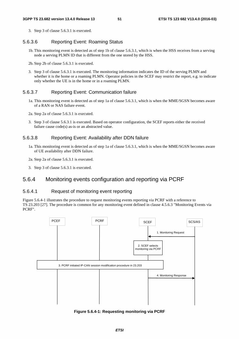
ETSI
ETSI TS 123 682 V13.4.0 (2016-03)513GPP TS 23.682 version 13.4.0 Release 13
3. Step 3 of clause 5.6.3.1 is executed.
5.6.3.6 Reporting Event: Roaming Status
1b. This monitoring event is detected as of step 1b of clause 5.6.3.1, which is when the HSS receives from a serving node a serving PLMN ID that is different from the one stored by the HSS.
2b. Step 2b of clause 5.6.3.1 is executed.
3. Step 3 of clause 5.6.3.1 is executed. The monitoring information indicates the ID of the serving PLMN and whether it is the home or a roaming PLMN. Operator policies in the SCEF may restrict the report, e.g. to indicate only whether the UE is in the home or in a roaming PLMN.
5.6.3.7 Reporting Event: Communication failure
1a. This monitoring event is detected as of step 1a of clause 5.6.3.1, which is when the MME/SGSN becomes aware of a RAN or NAS failure event.
2a. Step 2a of clause 5.6.3.1 is executed.
3. Step 3 of clause 5.6.3.1 is executed. Based on operator configuration, the SCEF reports either the received failure cause code(s) as-is or an abstracted value.
5.6.3.8 Reporting Event: Availability after DDN failure
1a. This monitoring event is detected as of step 1a of clause 5.6.3.1, which is when the MME/SGSN becomes aware of UE availability after DDN failure.
2a. Step 2a of clause 5.6.3.1 is executed.
3. Step 3 of clause 5.6.3.1 is executed.
5.6.4 Monitoring events configuration and reporting via PCRF
5.6.4.1 Request of monitoring event reporting
Figure 5.6.4-1 illustrates the procedure to request monitoring events reporting via PCRF with a reference to TS 23.203 [27]. The procedure is common for any monitoring event defined in clause 4.5.6.3 "Monitoring Events via PCRF".
SCS/AS PCRF PCEF SCEF
1. Monitoring Request
4. Monitoring Response
2. SCEF selects
monitoring via PCRF
3. PCRF initiated IP-CAN session modification procedure in 23.203
Figure 5.6.4-1: Requesting monitoring via PCRF
ETSI
ETSI TS 123 682 V13.4.0 (2016-03)523GPP TS 23.682 version 13.4.0 Release 13
1. The SCS/AS sends a Monitoring Request to the SCEF, including the information listed in clause 5.6.1.1.step 1 in figure 5.6.1.1-1.
2. The SCEF checks that the SCS/AS is authorised to send monitoring request as defined clause 5.6.1.1.step 2 in figure 5.6.1.1-1. If an error is detected, step 3 is skipped, and the message of step 4 is sent to SCS/AS with Cause value appropriately indicating the error.
3. If operator policies indicate that monitoring is performed via PCRF, for the events listed in clause 4.5.6, the SCEF, acting as an Application Function, triggers the PCRF initiated-IP-CAN session modification procedure defined in TS 23.203 [27].
4. The SCEF sends a Monitoring Response (SCS/AS Reference ID, Cause) message to the SCS/AS. If the SCEF received a Monitoring Event Report then it includes it in the Monitoring Response message.
5.6.4.2 Common Parameters of the request reporting procedure
The following parameters are applicable when the procedure for monitoring via PCRF is used: SCS/AS Reference ID, Monitoring Type, Priority, Monitoring Duration and Monitoring Destination Address.
The Monitoring types are defined in clause 4.5.6. The Priority is relevant to the SCEF, not transferred over Rx.
The following parameters are not applicable when the procedure for monitoring via PCRF is used: SCEF Address, SCEF Reference ID, and Maximum Number of Reports. The SCEF address is not needed as Rx procedures do not require the AF address to be sent. The Maximum Number of Reports is not needed as only one time report is supported.
The following parameters are needed for the procedure for monitoring via PCRF, the UE IP address and service information (e.g. application identifier or media description or both).
NOTE: The UE IP address provided by the SCS/AS is assumed to not be NAT'ed from the PDN-GW or GGSN to the SCS/AS at user plane. The UE IP address does not overlap with other UE IP addresses within the operator domain.
5.6.4.3 Specific Parameters for Monitoring Event: Location Reporting
This monitoring event allows the SCS/AS to request the Current Location. The supported location accuracy is at either cell level (CGI/ECGI/SAI) for GPRS/UTRAN/E-UTRAN or TWAN identifier in TWAN access or PLMN-id level. The Monitoring Event Report delivers the subscriber location and may include a time stamp to indicate when the UE was last-known to be in that location, i.e. if the current location or last-know location is provided.
NOTE: SCEF can map IP-CAN provided location to the location granularity required by SCS/AS only if it is configured to do so.
The description in this clause is applicable if SCS/AS request Monitoring Type to "Location Reporting" and Location Type is either "current location" or "last known location".
1. The SCS/AS sets Monitoring Type to "Location Reporting", and adds Location Type in a Monitoring Request to the SCEF as in step 1 of 5.6.4.1.
2. The SCEF executes step 2 of 5.6.4.1.
3. The SCEF triggers PCRF initiated IP-CAN session modification procedure, including the UE IP address and the Access Network information report request. The PCRF provides the Access Network Information report to the SCEF.
4. Based on operator policies, the SCEF translates the location information to a geo-location to be provided to SCS/AS. If the time stamp is included indicating that this is the last known location the SCEF indicates in the location type that this is last known location.
5.6.4.4 Specific Parameters for Monitoring Event: Communication Failure
This monitoring event allows the SCS/AS to be notified of communication failure events, identified by RAN/NAS or TWAN/UWAN Release Cause codes, per TS 23.203 [27].
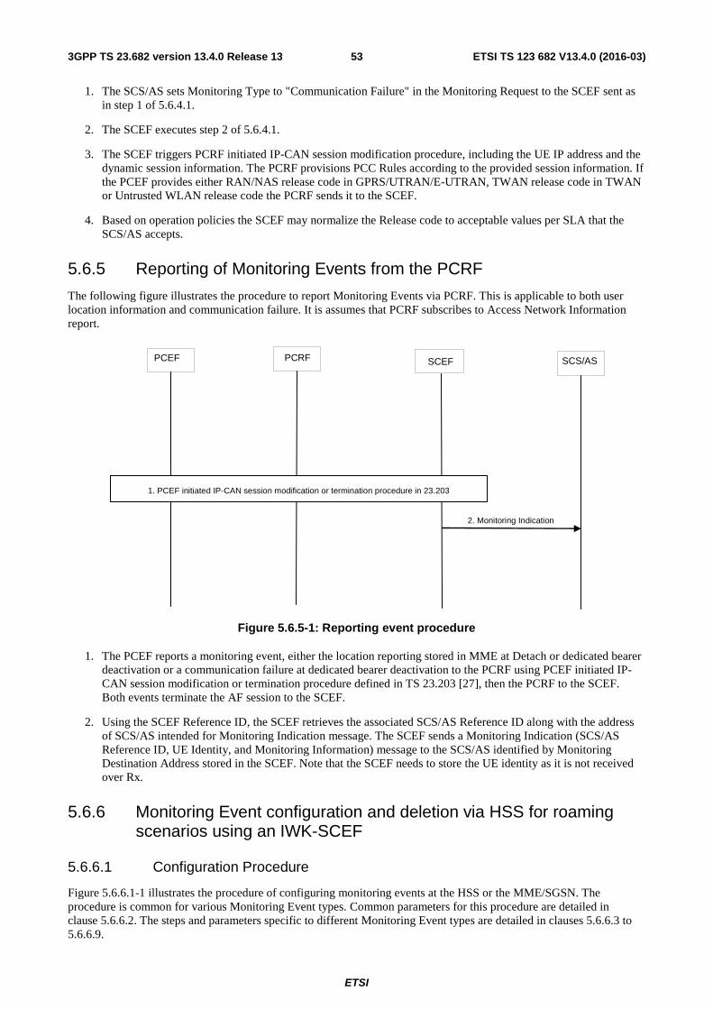
ETSI
ETSI TS 123 682 V13.4.0 (2016-03)533GPP TS 23.682 version 13.4.0 Release 13
1. The SCS/AS sets Monitoring Type to "Communication Failure" in the Monitoring Request to the SCEF sent as in step 1 of 5.6.4.1.
2. The SCEF executes step 2 of 5.6.4.1.
3. The SCEF triggers PCRF initiated IP-CAN session modification procedure, including the UE IP address and the dynamic session information. The PCRF provisions PCC Rules according to the provided session information. If the PCEF provides either RAN/NAS release code in GPRS/UTRAN/E-UTRAN, TWAN release code in TWAN or Untrusted WLAN release code the PCRF sends it to the SCEF.
4. Based on operation policies the SCEF may normalize the Release code to acceptable values per SLA that the SCS/AS accepts.
5.6.5 Reporting of Monitoring Events from the PCRF
The following figure illustrates the procedure to report Monitoring Events via PCRF. This is applicable to both user location information and communication failure. It is assumes that PCRF subscribes to Access Network Information report.
SCS/AS PCRF PCEF SCEF
2. Monitoring Indication
1. PCEF initiated IP-CAN session modification or termination procedure in 23.203
Figure 5.6.5-1: Reporting event procedure
1. The PCEF reports a monitoring event, either the location reporting stored in MME at Detach or dedicated bearer deactivation or a communication failure at dedicated bearer deactivation to the PCRF using PCEF initiated IP-CAN session modification or termination procedure defined in TS 23.203 [27], then the PCRF to the SCEF. Both events terminate the AF session to the SCEF.
2. Using the SCEF Reference ID, the SCEF retrieves the associated SCS/AS Reference ID along with the address of SCS/AS intended for Monitoring Indication message. The SCEF sends a Monitoring Indication (SCS/AS Reference ID, UE Identity, and Monitoring Information) message to the SCS/AS identified by Monitoring Destination Address stored in the SCEF. Note that the SCEF needs to store the UE identity as it is not received over Rx.
5.6.6 Monitoring Event configuration and deletion via HSS for roaming scenarios using an IWK-SCEF
5.6.6.1 Configuration Procedure
Figure 5.6.6.1-1 illustrates the procedure of configuring monitoring events at the HSS or the MME/SGSN. The procedure is common for various Monitoring Event types. Common parameters for this procedure are detailed in clause 5.6.6.2. The steps and parameters specific to different Monitoring Event types are detailed in clauses 5.6.6.3 to 5.6.6.9.
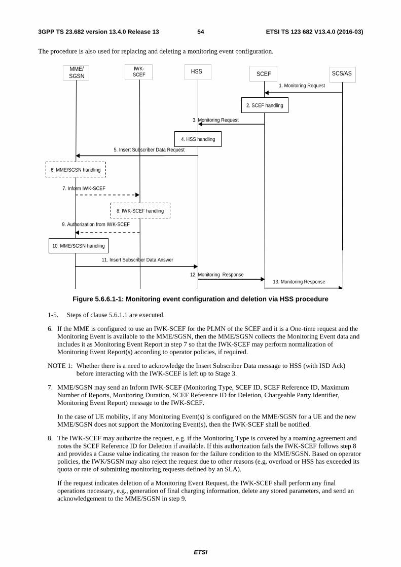
ETSI
ETSI TS 123 682 V13.4.0 (2016-03)543GPP TS 23.682 version 13.4.0 Release 13
The procedure is also used for replacing and deleting a monitoring event configuration.
SCS/AS HSS MME/
SGSN SCEF
1. Monitoring Request
13. Monitoring Response
2. SCEF handling
3. Monitoring Request
12. Monitoring Response
5. Insert Subscriber Data Request
11. Insert Subscriber Data Answer
4. HSS handling
6. MME/SGSN handling
IWK- SCEF
7. Inform IWK-SCEF
9. Authorization from IWK-SCEF
8. IWK-SCEF handling
10. MME/SGSN handling
Figure 5.6.6.1-1: Monitoring event configuration and deletion via HSS procedure
1-5. Steps of clause 5.6.1.1 are executed.
6. If the MME is configured to use an IWK-SCEF for the PLMN of the SCEF and it is a One-time request and the Monitoring Event is available to the MME/SGSN, then the MME/SGSN collects the Monitoring Event data and includes it as Monitoring Event Report in step 7 so that the IWK-SCEF may perform normalization of Monitoring Event Report(s) according to operator policies, if required.
NOTE 1: Whether there is a need to acknowledge the Insert Subscriber Data message to HSS (with ISD Ack) before interacting with the IWK-SCEF is left up to Stage 3.
7. MME/SGSN may send an Inform IWK-SCEF (Monitoring Type, SCEF ID, SCEF Reference ID, Maximum Number of Reports, Monitoring Duration, SCEF Reference ID for Deletion, Chargeable Party Identifier, Monitoring Event Report) message to the IWK-SCEF.
In the case of UE mobility, if any Monitoring Event(s) is configured on the MME/SGSN for a UE and the new MME/SGSN does not support the Monitoring Event(s), then the IWK-SCEF shall be notified.
8. The IWK-SCEF may authorize the request, e.g. if the Monitoring Type is covered by a roaming agreement and notes the SCEF Reference ID for Deletion if available. If this authorization fails the IWK-SCEF follows step 8 and provides a Cause value indicating the reason for the failure condition to the MME/SGSN. Based on operator policies, the IWK/SGSN may also reject the request due to other reasons (e.g. overload or HSS has exceeded its quota or rate of submitting monitoring requests defined by an SLA).
If the request indicates deletion of a Monitoring Event Request, the IWK-SCEF shall perform any final operations necessary, e.g., generation of final charging information, delete any stored parameters, and send an acknowledgement to the MME/SGSN in step 9.
ETSI
ETSI TS 123 682 V13.4.0 (2016-03)553GPP TS 23.682 version 13.4.0 Release 13
If the request indicates continuous reporting (new or a modification), the IWK-SCEF may authorize the request and, if authorization is successful, stores the received parameters, sends an acknowledgement to the MME/SGSN in step 9, and starts to watch for the indicated Monitoring Event(s).
If the request indicates one-time reporting, then the IWK-SCEF may authorize the request and, if authorization is successful, may perform normalization of the data according to operator policies, and sends an acknowledgement to the MME/SGSN in step 9 that contains any such normalized data.
If the request included Monitoring Event Data then the IWK-SCEF may perform normalization of the data according to operator policies.
9. If the authorization is successful, the IWK-SCEF sends an Authorization from IWK-SCEF (Cause, Monitoring Event Report) message to MME/SGSN.
The Monitoring Event Report is included in case it was a One-time request, the MME/SGSN provided the Monitoring Event Report in the Inform IWK-SCEF message and the IWK-SCEF is not reporting directly to the SCEF as described clause 5.6.8.1 step 2c.
10. The MME/SGSN may verify the request, e.g. if the Monitoring Type is covered by a roaming agreement when the request is from another PLMN or whether it serves the SCEF Reference ID for Deletion and can delete it. If this check fails the MME/SGSN follows step 11 and provides a Cause value indicating the reason for the failure condition to the SCEF. Based on operator policies, the MME/SGSN may also reject the request due to other reasons (e.g. overload or HSS has exceeded its quota or rate of submitting monitoring requests defined by an SLA).
The MME/SGSN starts to watch for the indicated Monitoring Event unless it is a One-time request and the Monitoring Event is available to the MME/SGSN at the time of sending Insert Subscriber Data Answer. The MME/SGSN deletes the monitoring configuration identified by the SCEF Reference ID for Deletion, if provided.
NOTE 2: The MME/SGSN will transfer the parameters stored for every monitoring task as part of its context information during an MME/SGSN change. If the UE detaches from the network, the HSS will receive the remaining number of reports in the Maximum Number of Reports parameter.
11. If the monitoring configuration is successful, the MME/SGSN sends an Insert Subscriber Data Answer (Cause) message to the HSS. If the requested Monitoring Event is available to the MME/SGSN at the time of sending Insert Subscriber Data Answer, then the MME/SGSN includes the Monitoring Event Report in the Insert Subscriber Data Answer message.
NOTE 3: Whether the normalized Monitoring Event Report(s) are carried in ISD Ack or in an explicit report message to the HSS is left up to Stage 3.
12. The HSS sends a Monitoring Response (SCEF Reference ID, Cause) message to the SCEF to acknowledge acceptance of the Monitoring Request and the deletion of the identified monitoring event configuration, if it was requested. The HSS deletes the monitoring event configuration identified by the SCEF Reference ID, if it was requested. If the requested Monitoring Event is available to the HSS at the time of sending Monitoring Response message or was received from the MME/SGSN in step 11, then the HSS includes a Monitoring Event Report in the Monitoring Response message.
If it is a One-time request and the Insert Subscriber Data Answer includes a Monitoring Event Report, the HSS deletes the associated Monitoring Event configuration.
In the case of UE mobility, the HSS determines whether the new MME/SGSN supports requested Monitoring Event(s).
13. The SCEF sends a Monitoring Response (SCS/AS Reference ID, Cause) message to the SCS/AS to acknowledge acceptance of the Monitoring Request and the deletion of the identified monitoring event configuration, if it was requested. If the SCEF received a Monitoring Event Report then it includes the Monitoring Event Report in the Monitoring Response message. If it is a One-time request and the Monitoring Response includes a Monitoring Event Report, the SCEF deletes the associated Monitoring Event configuration.
If the HSS detects that the current serving MME/SGSN can not support a requested Monitoring Event (e.g. after a UE mobility event), the HSS performs the procedures in either (a) or (b) below. The criteria used to determine the choice of (a) or (b) is considered out of scope of the specifications.
ETSI
ETSI TS 123 682 V13.4.0 (2016-03)563GPP TS 23.682 version 13.4.0 Release 13
(a) Notify the SCEF that the configured Monitoring Event is cancelled, and:
- shall delete the Monitoring Event, if the Monitoring Event is configured in the HSS, and
- may include a "retry after" value to inform the SCEF of when (re)-configuration of the Monitoring Event(s) can be attempted again. The "retry after" value can be configured in the HSS by the operator. The SCEF can further notify the SCS/AS and provide the "retry after" value to the SCS/AS.
(b) Notify the SCEF that the configured Monitoring Event is considered to be suspended. The SCEF interprets this to mean that the network will temporarily be unable to serve the configured Monitoring Event In this case:
- When the MME/SGSN for the UE changes (eg due to UE mobility), and the new MME/SGSN supports the suspended Monitoring Event, the HSS shall configure the new MME/SGSN with the Monitoring Event and notify the SCEF of resumption of the suspended Monitoring Event;
- If the criteria for Continuous Reporting expire while the Monitoring Event is suspended, the HSS and the SCEF shall independently delete the Monitoring Event.
5.6.6.2 Common Parameters of the Configuration Procedure
This clause describes the common parameters related to the monitoring event configuration procedure for roaming scenarios by clarifying the differences compared to the non-roaming scenarios described in clause 5.6.1.2.
The description in clause 5.6.1.2 applies with the following clarifications.
SCEF Reference ID is stored by HSS, MME, SGSN and IWK-SCEF.
SCEF ID indicates the SCEF to which the Monitoring Indication message has to be sent to by the HSS, MME, SGSN or IWK-SCEF. SCEF ID is stored by the HSS, MME, SGSN and IWK-SCEF.
5.6.6.3 Specific Parameters for Monitoring Event: Loss of connectivity
The description in clause 5.6.1.3 applies with the following clarifications.
1-5. Steps of clause 5.6.1.3 are executed.
6. The MME/SGSN executes step 6 of clause 5.6.1.3, but if the values proposed by HSS is not acceptable to the MME/SGSN the MME/SGSN rejects the request and includes acceptable values in the reject message.
7-9. Steps of clause 5.6.1.3 are executed.
5.6.6.4 Specific Parameters for Monitoring Event: UE reachability
The description in clause 5.6.1.4 applies with the following clarifications.
1-5. Steps of clause 5.6.1.4 are executed.
6. The MME/SGSN executes step 6 of clause 5.6.1.4, but if the values proposed by HSS is not acceptable to the MME/SGSN the MME/SGSN rejects the request and includes acceptable values in the reject message.
7-9. Steps of clause 5.6.1.4 are executed.
5.6.6.5 Specific Parameters for Monitoring Event: Location Reporting
The description in clause 5.6.1.5 applies with the following clarifications.
1-2. As described in clause 5.6.1.5.
3. If Accuracy is included in step 1 then based on operator configuration the SCEF may map it to permissible granularity at cell level (CGI/ECGI), eNodeB level or TA/RA level. If Accuracy is not included in step 1, the SCEF sets the granularity based on operator configuration. The SCEF adds Location Type and Accuracy prior to sending the Monitoring Request to the HSS as in step 3 of clause 5.6.1.5.
4. As described in clause 5.6.1.5.
ETSI
ETSI TS 123 682 V13.4.0 (2016-03)573GPP TS 23.682 version 13.4.0 Release 13
5. As described in clause 5.6.1.5.
6. If the MME/SGSN is configured to use an IWK-SCEF for the PLMN of the SCEF and it is a One-time request, the MME/SGSN starts watching for cell/RA/TA/eNodeB changes, depending on requested Accuracy, and includes the location information as part of the Monitoring Event Data to the IWK-SCEF in step 7.
7. If the MME/SGSN is configured to use an IWK-SCEF for the PLMN of the SCEF, then the MME/SGSN shall execute the step 7 in clause 5.6.6.1.
8. The IWK-SCEF executes step 8 in clause 5.6.6.1, and if the request included Monitoring Event Data then the IWK-SCEF may perform normalization of the data according to operator policies.
9. The IWK-SCEF executes step 9 in clause 5.6.6.1.
10. If the MME/SGSN is configured to use an IWK-SCEF for the PLMN of the SCEF, then the MME/SGSN either starts to watch for the indicated Monitoring Event, or if the IWK-SCEF rejected the request the MME/SGSN rejects the request with the cause provided by the IWK-SCEF.
If the MME/SGSN is not configured to use an IWK-SCEF for the PLMN of the SCEF, then the MME/SGSN executes step 6 of clause 5.6.1.1 and in addition perform any actions required e.g. generating charging/accounting information.
11-13. Steps 7-9 of clause 5.6.1.1 are executed and include the report of the current or last known location, depending on what was requested. The SCEF, if not already done by the IWK-SCEF, maps eNodeB-ID/cell-ID/RAI/TAI to geo-location before reporting to the SCS/AS.
5.6.6.6 Specific Parameters for Monitoring Event: Change of IMSI-IMEI(SV) Association
The description in clause 5.6.1.6 applies as there are no VPLMN changes.
5.6.6.7 Specific Parameters for Monitoring Event: Roaming Status
The description in clause 5.6.1.6 applies as there are no VPLMN changes.
5.6.6.8 Specific Parameters for Monitoring Event: Communication failure
The description in clause 5.6.1.8 applies with the following clarifications.
1. The SCS/AS sets Monitoring Type to "Communication Failure" prior to sending Monitoring Request to the SCEF as in step 1 of clause 5.6.1.8.
2. The SCEF executes step 2 of clause 5.6.1.8.
3. The SCEF executes step 3 of clause 5.6.1.8.
4. The HSS executes step 4 of clause 5.6.1.8.
5. The HSS executes step 5 of clause 5.6.1.8.
6. Not applicable.
7. If the MME/SGSN is configured to use an IWK-SCEF for the PLMN of the SCEF, the MME/SGSN executes step 7 of 5.6.6.1.
8. The IWK-SCEF executes step 8 of clause 5.6.6.1.
9. The IWK-SCEF executes step 9 of clause 5.6.6.1.
10. The MME/SGSN executes step 6 of clause 5.6.1.8 and starts watching for communication failure events.
11-13. Steps 7-9 of clause 5.6.1.8 are executed.
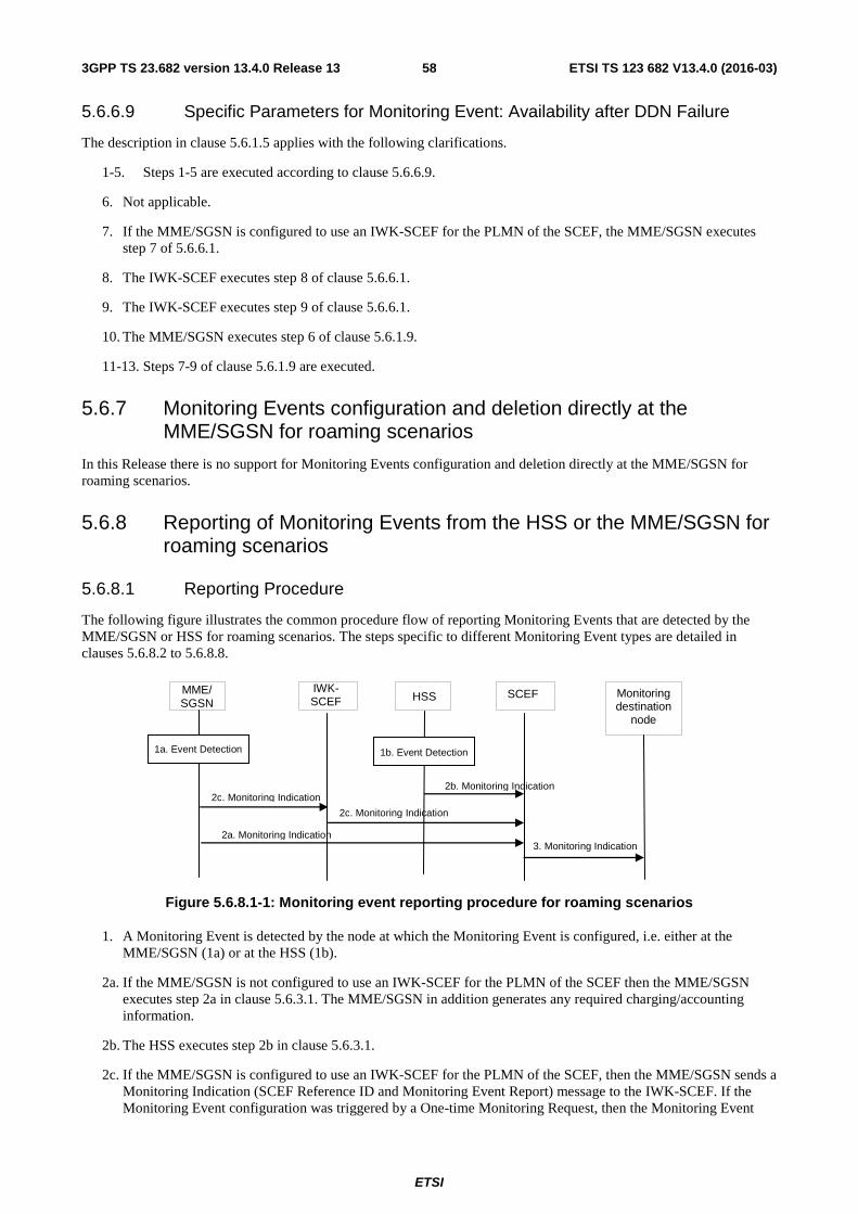
ETSI
ETSI TS 123 682 V13.4.0 (2016-03)583GPP TS 23.682 version 13.4.0 Release 13
5.6.6.9 Specific Parameters for Monitoring Event: Availability after DDN Failure
The description in clause 5.6.1.5 applies with the following clarifications.
1-5. Steps 1-5 are executed according to clause 5.6.6.9.
6. Not applicable.
7. If the MME/SGSN is configured to use an IWK-SCEF for the PLMN of the SCEF, the MME/SGSN executes step 7 of 5.6.6.1.
8. The IWK-SCEF executes step 8 of clause 5.6.6.1.
9. The IWK-SCEF executes step 9 of clause 5.6.6.1.
10. The MME/SGSN executes step 6 of clause 5.6.1.9.
11-13. Steps 7-9 of clause 5.6.1.9 are executed.
5.6.7 Monitoring Events configuration and deletion directly at the MME/SGSN for roaming scenarios
In this Release there is no support for Monitoring Events configuration and deletion directly at the MME/SGSN for roaming scenarios.
5.6.8 Reporting of Monitoring Events from the HSS or the MME/SGSN for roaming scenarios
5.6.8.1 Reporting Procedure
The following figure illustrates the common procedure flow of reporting Monitoring Events that are detected by the MME/SGSN or HSS for roaming scenarios. The steps specific to different Monitoring Event types are detailed in clauses 5.6.8.2 to 5.6.8.8.
Monitoring destination
node
HSS
1a. Event Detection
2b. Monitoring Indication
3. Monitoring Indication
MME/ SGSN
2c. Monitoring Indication
SCEF IWK-SCEF
2c. Monitoring Indication
2a. Monitoring Indication
1b. Event Detection
Figure 5.6.8.1-1: Monitoring event reporting procedure for roaming scenarios
1. A Monitoring Event is detected by the node at which the Monitoring Event is configured, i.e. either at the MME/SGSN (1a) or at the HSS (1b).
2a. If the MME/SGSN is not configured to use an IWK-SCEF for the PLMN of the SCEF then the MME/SGSN executes step 2a in clause 5.6.3.1. The MME/SGSN in addition generates any required charging/accounting information.
2b. The HSS executes step 2b in clause 5.6.3.1.
2c. If the MME/SGSN is configured to use an IWK-SCEF for the PLMN of the SCEF, then the MME/SGSN sends a Monitoring Indication (SCEF Reference ID and Monitoring Event Report) message to the IWK-SCEF. If the Monitoring Event configuration was triggered by a One-time Monitoring Request, then the Monitoring Event
ETSI
ETSI TS 123 682 V13.4.0 (2016-03)593GPP TS 23.682 version 13.4.0 Release 13
configuration is deleted by the MME/SGSN upon completion of this step. If the MME/SGSN has a Maximum Number of Reports stored for this monitoring task, the MME/SGSN shall decrease its value by one.
The IWK-SCEF sends a Monitoring Indication (SCEF Reference ID and Monitoring Event Report) message to the SCEF. If the IWK-SCEF has a Maximum Number of Reports stored for this monitoring task, the MME/SGSN shall decrease its value by one. When the maximum number of reports is reached for a Continuous Monitoring Request or in case of a One-time Monitoring Request, the IWK-SCEF ends the reporting on the SCEF Reference ID.
3. The SCEF executes step 3 in clause 5.6.3.1.
5.6.8.2 Reporting Event: Loss of connectivity
1a. This monitoring event is detected as of step 1a of clause 5.6.8.1, which is when the mobile reachability timer expires.
2. Dependent on MME/SGSN configuration step 2a or 2c of clause 5.6.8.1 is executed.
3. Step 3 of clause 5.6.8.1 is executed.
5.6.8.3 Reporting Event: UE reachability
1a. This monitoring event is detected as of step 1a of clause 5.6.8.1, which is when the UE changes to connected mode.
If Maximum Response Time was included in step 5 of clause 5.6.6.4, then the MME/SGSN keeps the corresponding S1-U/Iu-PS connections of the UE for a duration of at least the Maximum Response Time less the UE's PSM Active Timer value.
2. Dependent on MME/SGSN configuration step 2a or 2c of clause 5.6.8.1 is executed.
3. Step 3 of clause 5.6.8.1 is executed.
5.6.8.4 Reporting Event: Location Reporting
1a. This monitoring event is detected as of step 1a of clause 5.6.8.1, which is when the MME/SGSN detects that the UE changes location with the granularity as requested by the monitoring event configuration.
2. Dependent on MME/SGSN configuration step 2a or 2c of clause 5.6.8.1 is executed. If step 2c is executed, then the IWK-SCEF maps the reported 3GPP system specific location information to a geo-location and forwards it to the SCEF.
3. Step 3 of clause 5.6.8.1 is executed. The SCEF may map the reported 3GPP system specific location information to a geo-location and reports it.
5.6.8.5 Reporting Event: Change of IMSI-IMEI(SV) association
This monitoring event is executes as in clause 5.6.3.5.
5.6.8.6 Reporting Event: Roaming Status
This monitoring event is executes as in clause 5.6.3.6.
5.6.8.7 Reporting Event: Communication failure
1a. This monitoring event is detected as of step 1a of clause 5.6.8.1, which is when the MME/SGSN becomes aware of a RAN or NAS failure event.
2. Dependent on MME/SGSN configuration step 2a or 2c of clause 5.6.8.1 is executed. If step 2c is executed, then the IWK-SCEF either forwards the the received failure cause code(s) as-is or an abstracted value to the SCEF.
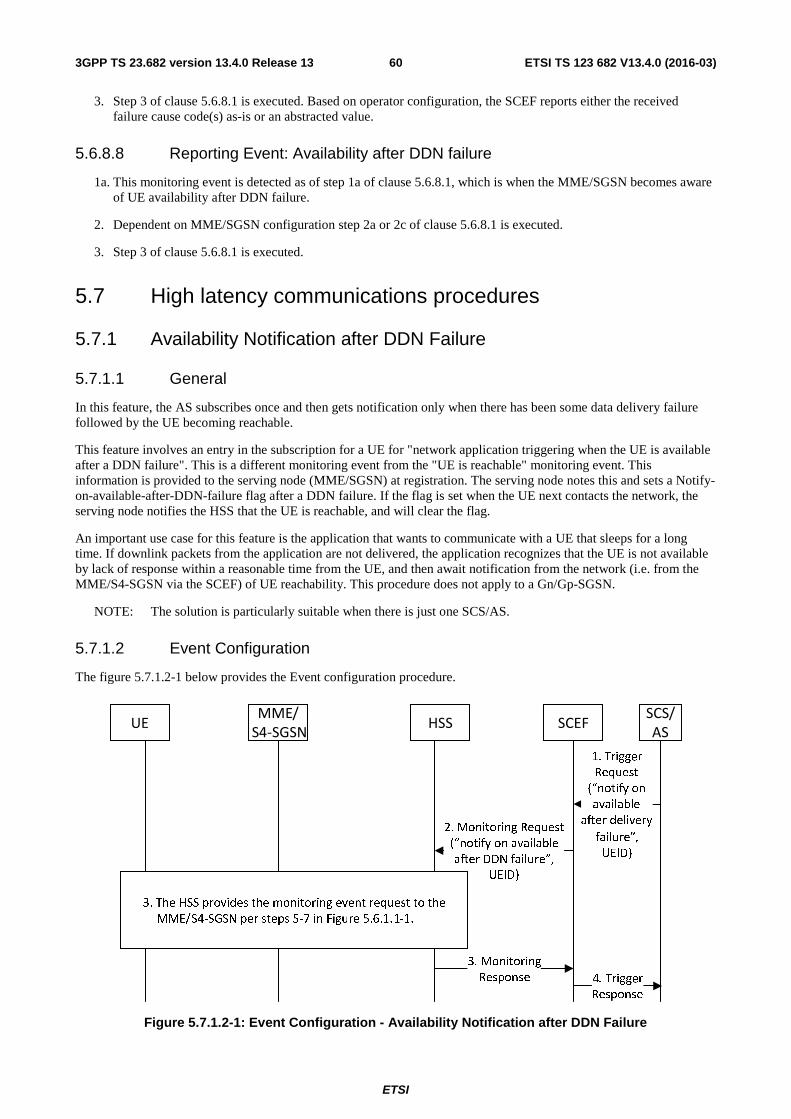
ETSI
ETSI TS 123 682 V13.4.0 (2016-03)603GPP TS 23.682 version 13.4.0 Release 13
3. Step 3 of clause 5.6.8.1 is executed. Based on operator configuration, the SCEF reports either the received failure cause code(s) as-is or an abstracted value.
5.6.8.8 Reporting Event: Availability after DDN failure
1a. This monitoring event is detected as of step 1a of clause 5.6.8.1, which is when the MME/SGSN becomes aware of UE availability after DDN failure.
2. Dependent on MME/SGSN configuration step 2a or 2c of clause 5.6.8.1 is executed.
3. Step 3 of clause 5.6.8.1 is executed.
5.7 High latency communications procedures
5.7.1 Availability Notification after DDN Failure
5.7.1.1 General
In this feature, the AS subscribes once and then gets notification only when there has been some data delivery failure followed by the UE becoming reachable.
This feature involves an entry in the subscription for a UE for "network application triggering when the UE is available after a DDN failure". This is a different monitoring event from the "UE is reachable" monitoring event. This information is provided to the serving node (MME/SGSN) at registration. The serving node notes this and sets a Notify-on-available-after-DDN-failure flag after a DDN failure. If the flag is set when the UE next contacts the network, the serving node notifies the HSS that the UE is reachable, and will clear the flag.
An important use case for this feature is the application that wants to communicate with a UE that sleeps for a long time. If downlink packets from the application are not delivered, the application recognizes that the UE is not available by lack of response within a reasonable time from the UE, and then await notification from the network (i.e. from the MME/S4-SGSN via the SCEF) of UE reachability. This procedure does not apply to a Gn/Gp-SGSN.
NOTE: The solution is particularly suitable when there is just one SCS/AS.
5.7.1.2 Event Configuration
The figure 5.7.1.2-1 below provides the Event configuration procedure.
HSS
SCS/
AS
MME/
S4-SGSNUE
2. Monitoring Request
(“notify on available
after DDN failure”,
UEID)
3. Monitoring
Response
3 . The HSS provides the monitoring event request to the
MME/S4-SGSN per steps 5-7 in Figure 5.6.1.1-1.
SCEF
1. Trigger
Request
(“notify on
available
after delivery
failure”,
UEID)
4. Trigger
Response
Figure 5.7.1.2-1: Event Configuration - Availability Notification after DDN Failure
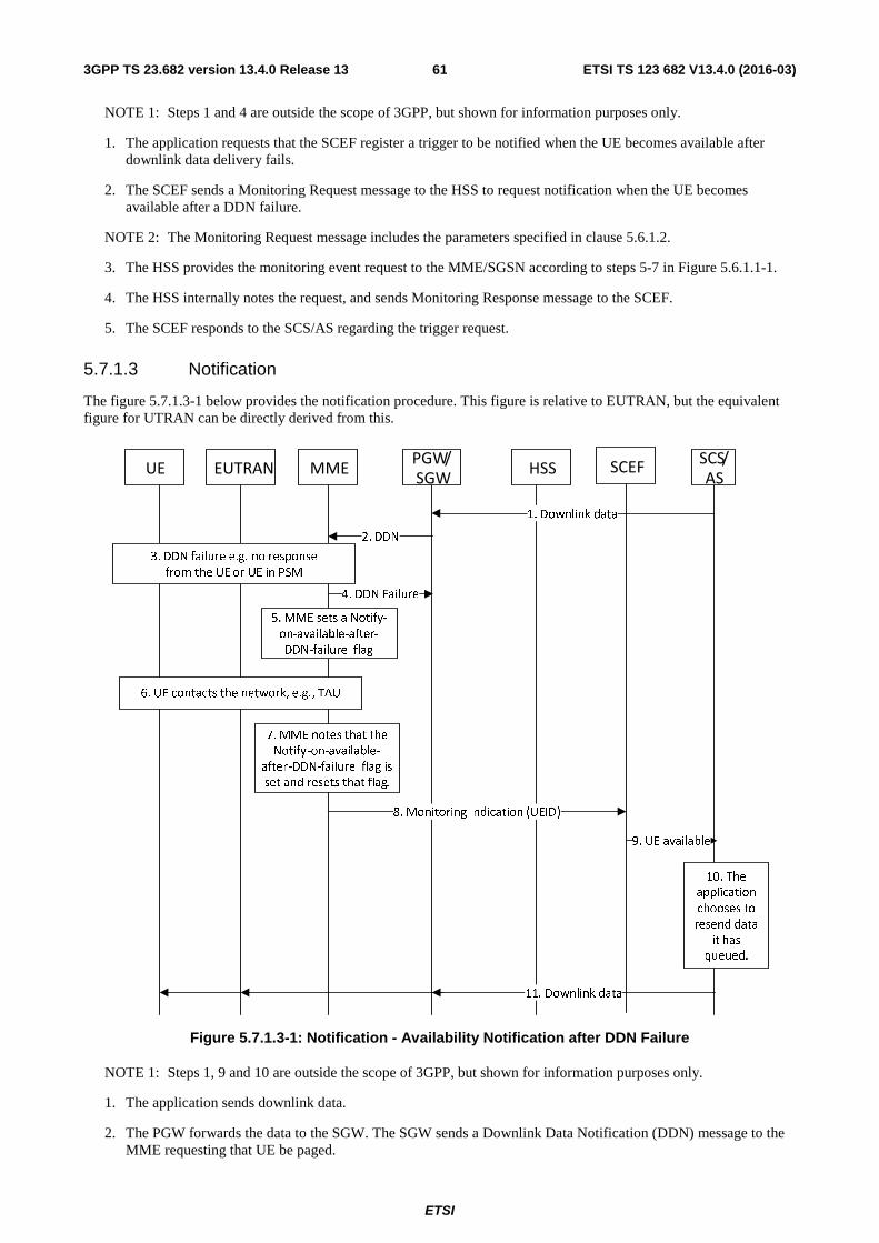
ETSI
ETSI TS 123 682 V13.4.0 (2016-03)613GPP TS 23.682 version 13.4.0 Release 13
NOTE 1: Steps 1 and 4 are outside the scope of 3GPP, but shown for information purposes only.
1. The application requests that the SCEF register a trigger to be notified when the UE becomes available after downlink data delivery fails.
2. The SCEF sends a Monitoring Request message to the HSS to request notification when the UE becomes available after a DDN failure.
NOTE 2: The Monitoring Request message includes the parameters specified in clause 5.6.1.2.
3. The HSS provides the monitoring event request to the MME/SGSN according to steps 5-7 in Figure 5.6.1.1-1.
4. The HSS internally notes the request, and sends Monitoring Response message to the SCEF.
5. The SCEF responds to the SCS/AS regarding the trigger request.
5.7.1.3 Notification
The figure 5.7.1.3-1 below provides the notification procedure. This figure is relative to EUTRAN, but the equivalent figure for UTRAN can be directly derived from this.
HSS
SCS/
ASMMEUE
1. Downlink data
4. DDN Failure
3. DDN failure e.g. no response
from the UE or UE in PSM
PGW/
SGWEUTRAN
2. DDN
5. MME sets a Notify-
on-available-after-
DDN-failure flag
6. UE contacts the network, e.g., TAU
7. MME notes that the
Notify-on-available-
after-DDN-failure flag is
set and resets that flag.
8. Monitoring Indication (UEID)
10. The
application
chooses to
resend data
it has
queued.
11. Downlink data
SCEF
9. UE available
Figure 5.7.1.3-1: Notification - Availability Notification after DDN Failure
NOTE 1: Steps 1, 9 and 10 are outside the scope of 3GPP, but shown for information purposes only.
1. The application sends downlink data.
2. The PGW forwards the data to the SGW. The SGW sends a Downlink Data Notification (DDN) message to the MME requesting that UE be paged.
ETSI
ETSI TS 123 682 V13.4.0 (2016-03)623GPP TS 23.682 version 13.4.0 Release 13
3. The MME initiates paging for UE but receives no response or the UE is in Power Saving Mode.
4. The MME sends a DDN failure indication to the SGW.
5. The MME notes the subscription option for notification of availability after DDN failure for the UE, and sets a Notify-on-available-after-DDN-failure flag. Not every DDN failure triggers this event. This event may be triggered only when the UE is in PSM.
6. At some later time, the UE contacts the network, e.g., to perform a TAU, or as it executes a service request.
7. The MME notes that UE is available and that the Notify-on-available-after-DDN-failure flag for the UE is set.
8. The MME sends a Monitoring Indication to the SCEF that the UE is available, according to clause 5.6.3.1. The MME also resets the Notify-on-available-after-DDN-failure flag for the UE.
9. The SCEF notifies the application that the UE is available.
10. The application decides to resend data it has queued for the UE.
11. The application sends the queued data toward the UE.
5.7.2 Notification using Monitoring Event "UE Reachability"
If an SCS/AS wants to send downlink packet(s), the SCS/AS can request a One-time "UE Reachability" monitoring event by sending Monitoring Request message indicating Reachability Type as "Reachability for Data". The SCS/AS sends the packet data when it receives notification that the UE is reachable. If the SCS/AS optionally wants to fine-tune the delivery of the downlink data within the time-window when the UE is reachable, the SCS/AS can configure optional parameter 'Maximum Response Time' with proper value (as detailed in clause 5.6.1.4).
5.8 Procedure for Informing about Potential Network Issues
5.8.1 General
This clause contains the detailed description and the procedures for the service capability exposure feature Informing about Potential Network Issues.
An SCS/AS may request for being notified about the network status. The following methods are supported:
- The SCS/AS requests to be informed, one-time, about the network status by providing a geographical area. This procedure is referred to as one-time network status request;
- The SCS/AS requests to be informed, continuously, about the network status by providing a geographical area. This procedure is referred to as continuous network status request.
NOTE 1: The SCS/AS - SCEF reference point is outside the scope of this specification. Messages on this reference point are considered as informative.
The procedures described in this clause use the RAN Congestion Awareness Function (RCAF) and corresponding features as defined in TS 23.401 [7] and TS 23.060 [6]. The SCEF communicates with the RCAF via the Ns reference point.
After receiving the request for network status notification from the SCS/AS, the SCEF derives the RCAF(s) responsible for the indicated geographical area, and requests congestion reporting from these RCAF(s).
NOTE 2: The SCEF needs to know the RCAF(s) available in the operator network or the network of the RAN operator in case of RAN sharing. For every RCAF, the SCEF needs to be configured with the RCAF address and the geographical area the RCAF is responsible for. The Ns reference point does not support roaming.
The RCAF reports to the SCEF the following information from the RUCI (see TS 23.203 [27]) for every cell or eNodeB belonging to the indicated geographical area:
- Congestion level or an indication of the "no congestion" state;
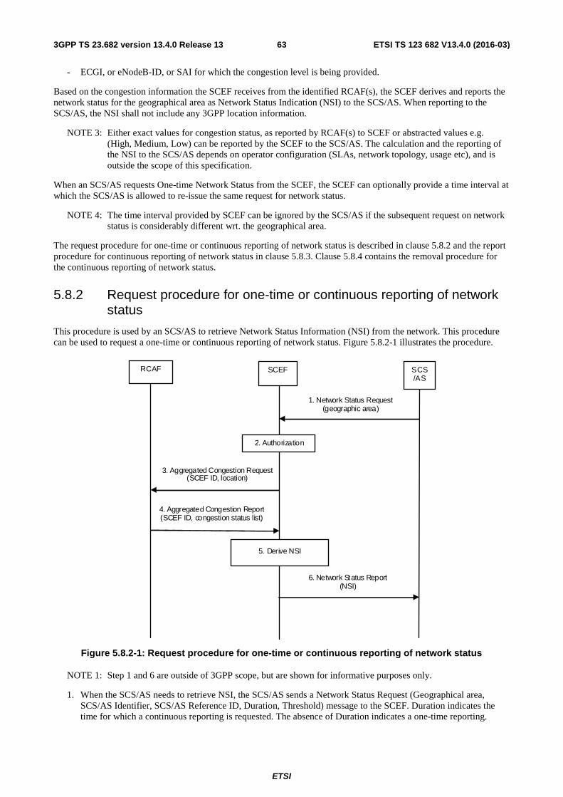
ETSI
ETSI TS 123 682 V13.4.0 (2016-03)633GPP TS 23.682 version 13.4.0 Release 13
- ECGI, or eNodeB-ID, or SAI for which the congestion level is being provided.
Based on the congestion information the SCEF receives from the identified RCAF(s), the SCEF derives and reports the network status for the geographical area as Network Status Indication (NSI) to the SCS/AS. When reporting to the SCS/AS, the NSI shall not include any 3GPP location information.
NOTE 3: Either exact values for congestion status, as reported by RCAF(s) to SCEF or abstracted values e.g. (High, Medium, Low) can be reported by the SCEF to the SCS/AS. The calculation and the reporting of the NSI to the SCS/AS depends on operator configuration (SLAs, network topology, usage etc), and is outside the scope of this specification.
When an SCS/AS requests One-time Network Status from the SCEF, the SCEF can optionally provide a time interval at which the SCS/AS is allowed to re-issue the same request for network status.
NOTE 4: The time interval provided by SCEF can be ignored by the SCS/AS if the subsequent request on network status is considerably different wrt. the geographical area.
The request procedure for one-time or continuous reporting of network status is described in clause 5.8.2 and the report procedure for continuous reporting of network status in clause 5.8.3. Clause 5.8.4 contains the removal procedure for the continuous reporting of network status.
5.8.2 Request procedure for one-time or continuous reporting of network status
This procedure is used by an SCS/AS to retrieve Network Status Information (NSI) from the network. This procedure can be used to request a one-time or continuous reporting of network status. Figure 5.8.2-1 illustrates the procedure.
RCAF SCEF
2. Authorization
1. Network Status Request (geographic area)
SCS/AS
6. Network Status Report (NSI)
3. Aggregated Congestion Request (SCEF ID, location)
4. Aggregated Congestion Report(SCEF ID, congestion status list)
5. Derive NSI
Figure 5.8.2-1: Request procedure for one-time or continuous reporting of network status
NOTE 1: Step 1 and 6 are outside of 3GPP scope, but are shown for informative purposes only.
1. When the SCS/AS needs to retrieve NSI, the SCS/AS sends a Network Status Request (Geographical area, SCS/AS Identifier, SCS/AS Reference ID, Duration, Threshold) message to the SCEF. Duration indicates the time for which a continuous reporting is requested. The absence of Duration indicates a one-time reporting.
ETSI
ETSI TS 123 682 V13.4.0 (2016-03)643GPP TS 23.682 version 13.4.0 Release 13
Threshold indicates a range at which the SCS/AS wishes to be informed of the network status. Multiple Threshold values may be included.
NOTE 2: Geographical area specified by SCS/AS could be at cell level (CGI/ECGI), TA/RA level or other formats e.g. shapes (e.g. polygons, circles etc.) or civic addresses (e.g. streets, districts etc.) as referenced by OMA Presence API [32].
2. The SCEF authorizes the SCS/AS request for notifications about potential network issues. The SCEF stores SCS/AS Address, SCS/AS Reference ID, Duration, if present and Threshold if present. The SCEF assigns an SCEF Reference ID.
NOTE 3: Based on operator policies, if either the SCS/AS is not authorized to perform this request (e.g. if the SLA does not allow for it) or the SCS/AS has exceeded its quota or rate of submitting requests, the SCEF sends a Network Status Response (Cause) message with a Cause value appropriately indicating the error.
3. The SCEF assigns an SCEF Reference ID and identifies, based on local configuration (as described in clause 5.8.1), the RCAF(s) responsible for the provided Geographical Area. For every identified RCAF, the SCEF derives a Location Area from the Geographical Area provided by the SCS/AS. The Location Area is according to operator configuration either a 3GPP location area (e.g. list of TA/RAs, list of cell(s), list of eNodeBs etc) or a sub-area of the Geographical Area provided by the SCS/AS. The SCEF sends an Aggregated Congestion Request (SCEF Reference ID, Location Area, Duration, Threshold) message to the identified RCAF(s). Duration indicates the time for which a continuous reporting is requested. The absence of Duration indicates a one-time reporting. The SCEF, based on operator policies, may chose a different Threshold value than the one indicated by the SCS/AS in step 1.
4. The RCAF examines the Aggregated Congestion Request message. If the SCEF provided a Duration, the RCAF stores the SCEF instructions and starts to monitor the set of cells or eNodeBs belonging to the Location Area for a change in the congestion status that is crossing a Threshold (if provided by the SCEF). The RCAF sends an Aggregated Congestion Report to the SCEF including the SCEF Reference ID and, depending on the operator configuration and current RCAF knowledge, the congestion status for every cell or eNodeB belonging to the Location Area requested by the SCEF.
5. The SCEF verifies whether the Network Status Request identified via the SCEF Reference ID is valid and active and stores the report. After receiving reports from all the involved RCAF(s) to which step 3 was executed, the SCEF derives the NSI for the requested Geographical Area by combining all reports with the same SCEF Reference ID in an operator configurable way (governed by SLAs, network topology, usage etc).
NOTE 4: Either exact values for congestion status, as reported by RCAF(s) to SCEF or abstracted values e.g. (High, Medium, Low) can be reported by the SCEF to the SCS/AS. The calculation and the reporting of the NSI to the SCS/AS depends on operator configuration (SLAs, network topology, usage etc), and is outside the scope of this specification.
6. The SCEF send a Network Status Report (SCS/AS Reference ID, NSI) message to the SCS/AS.
5.8.3 Report procedure for continuous reporting of network status
This procedure is used by the SCEF to report a change of Network Status Information (NSI) to the SCS/AS which requested a continuous reporting of network status. Figure 5.8.3-1 illustrates the procedure.
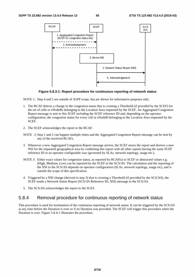
ETSI
ETSI TS 123 682 V13.4.0 (2016-03)653GPP TS 23.682 version 13.4.0 Release 13
RCAF SCEF SCS/AS
4. Network Status Report (NSI)
1. Aggregated Congestion Report (SCEF ID, congestion status list)
2. Acknowledgement
5. Acknowledgement
3. Derive NSI
Figure 5.8.3-1: Report procedure for continuous reporting of network status
NOTE 1: Step 4 and 5 are outside of 3GPP scope, but are shown for informative purposes only.
1. The RCAF detects a change in the congestion status that is crossing a Threshold (if provided by the SCEF) for the set of cells or eNodeBs belonging to the Location Area requested by the SCEF. An Aggregated Congestion Report message is sent to this SCEF including the SCEF reference ID and, depending on the operator configuration, the congestion status for every cell or eNodeB belonging to the Location Area requested by the SCEF.
2. The SCEF acknowledges the report to the RCAF.
NOTE 2: Step 1 and 2 can happen multiple times and the Aggregated Congestion Report message can be sent by any of the involved RCAFs.
3. Whenever a new Aggregated Congestion Report message arrives, the SCEF stores the report and derives a new NSI for the requested geographical area by combining this report with all other reports having the same SCEF reference ID in an operator configurable way (governed by SLAs, network topology, usage etc.).
NOTE 3: Either exact values for congestion status, as reported by RCAF(s) to SCEF or abstracted values e.g. (High, Medium, Low) can be reported by the SCEF to the SCS/AS. The calculation and the reporting of the NSI to the SCS/AS depends on operator configuration (SLAs, network topology, usage etc), and is outside the scope of this specification.
4. Triggered by a NSI change (derived in step 3) that is crossing a Threshold (if provided by the SCS/AS), the SCEF sends a Network Status Report (SCS/AS Reference ID, NSI) message to the SCS/AS.
5. The SCS/AS acknowledges the report to the SCEF.
5.8.4 Removal procedure for continuous reporting of network status
This procedure is used for termination of the continuous reporting of network status. It can be triggered by the SCS/AS at any time before the Duration is over or if no Duration was provided. The SCEF will trigger this procedure when the Duration is over. Figure 5.8.4-1 illustrates the procedure.
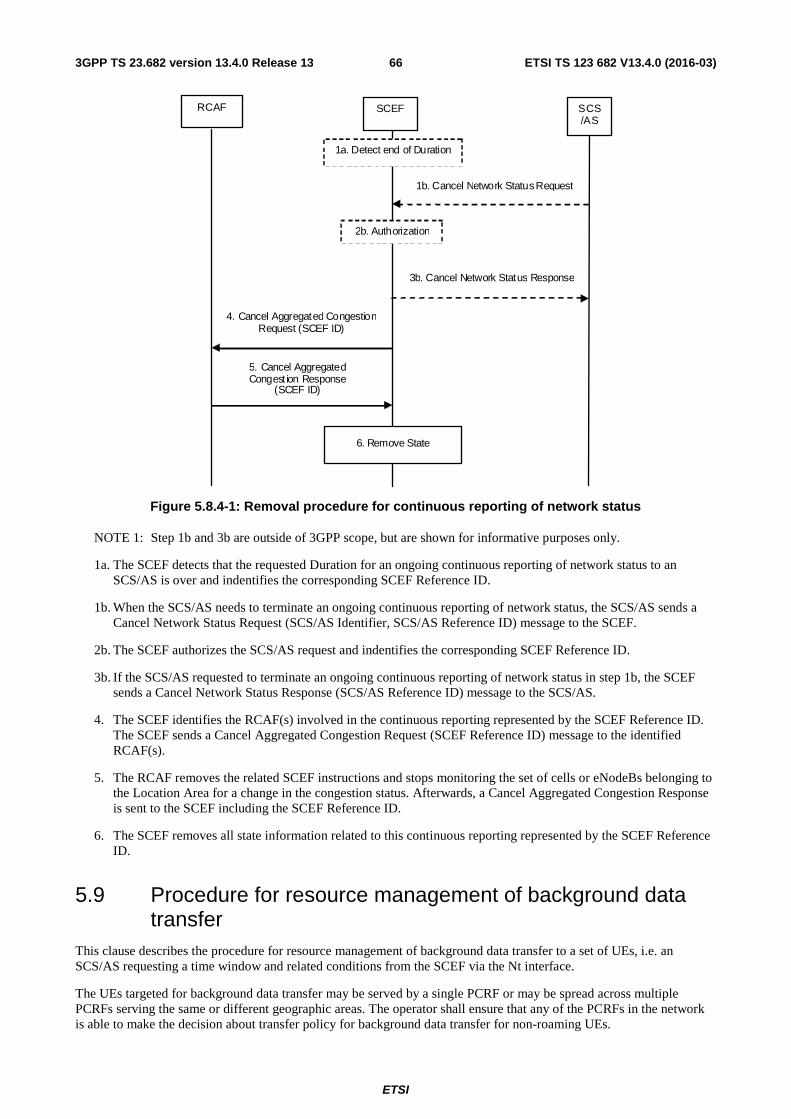
ETSI
ETSI TS 123 682 V13.4.0 (2016-03)663GPP TS 23.682 version 13.4.0 Release 13
RCAF SCEF
2b. Authorization
1b. Cancel Network Status Request
SCS/AS
3b. Cancel Network Status Response
4. Cancel Aggregated Congestion Request (SCEF ID)
5. Cancel Aggregated Congest ion Response
(SCEF ID)
6. Remove State
1a. Detect end of Duration
Figure 5.8.4-1: Removal procedure for continuous reporting of network status
NOTE 1: Step 1b and 3b are outside of 3GPP scope, but are shown for informative purposes only.
1a. The SCEF detects that the requested Duration for an ongoing continuous reporting of network status to an SCS/AS is over and indentifies the corresponding SCEF Reference ID.
1b. When the SCS/AS needs to terminate an ongoing continuous reporting of network status, the SCS/AS sends a Cancel Network Status Request (SCS/AS Identifier, SCS/AS Reference ID) message to the SCEF.
2b. The SCEF authorizes the SCS/AS request and indentifies the corresponding SCEF Reference ID.
3b. If the SCS/AS requested to terminate an ongoing continuous reporting of network status in step 1b, the SCEF sends a Cancel Network Status Response (SCS/AS Reference ID) message to the SCS/AS.
4. The SCEF identifies the RCAF(s) involved in the continuous reporting represented by the SCEF Reference ID. The SCEF sends a Cancel Aggregated Congestion Request (SCEF Reference ID) message to the identified RCAF(s).
5. The RCAF removes the related SCEF instructions and stops monitoring the set of cells or eNodeBs belonging to the Location Area for a change in the congestion status. Afterwards, a Cancel Aggregated Congestion Response is sent to the SCEF including the SCEF Reference ID.
6. The SCEF removes all state information related to this continuous reporting represented by the SCEF Reference ID.
5.9 Procedure for resource management of background data transfer
This clause describes the procedure for resource management of background data transfer to a set of UEs, i.e. an SCS/AS requesting a time window and related conditions from the SCEF via the Nt interface.
The UEs targeted for background data transfer may be served by a single PCRF or may be spread across multiple PCRFs serving the same or different geographic areas. The operator shall ensure that any of the PCRFs in the network is able to make the decision about transfer policy for background data transfer for non-roaming UEs.
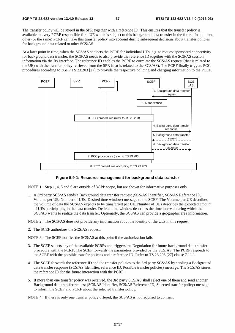
ETSI
ETSI TS 123 682 V13.4.0 (2016-03)673GPP TS 23.682 version 13.4.0 Release 13
The transfer policy will be stored in the SPR together with a reference ID. This ensures that the transfer policy is available to every PCRF responsible for a UE which is subject to this background data transfer in the future. In addition, other (or the same) PCRF can take this transfer policy into account during subsequent decisions about transfer policies for background data related to other SCS/AS.
At a later point in time, when the SCS/AS contacts the PCRF for individual UEs, e.g. to request sponsored connectivity for background data transfer, the SCS/AS needs to also provide the reference ID together with the SCS/AS session information via the Rx interface. The reference ID enables the PCRF to correlate the SCS/AS request (that is related to the UE) with the transfer policy retrieved from the SPR (that is related to the SCS/AS). The PCRF finally triggers PCC procedures according to 3GPP TS 23.203 [27] to provide the respective policing and charging information to the PCEF.
7. PCC procedures (refer to TS 23.203)
3. PCC procedures (refer to TS 23.203)
SCEF
2. Authorization
1. Background data transfer request
SCS/AS
PCRF
4. Background data transfer response
5. Background data transfer request
SPR PCEF
8. PCC procedures according to TS 23.203
6. Background data transfer response
Figure 5.9-1: Resource management for background data transfer
NOTE 1: Step 1, 4, 5 and 6 are outside of 3GPP scope, but are shown for informative purposes only.
1. A 3rd party SCS/AS sends a Background data transfer request (SCS/AS Identifier, SCS/AS Reference ID, Volume per UE, Number of UEs, Desired time window) message to the SCEF. The Volume per UE describes the volume of data the SCS/AS expects to be transferred per UE. Number of UEs describes the expected amount of UEs participating in the data transfer. Desired time window describes the time interval during which the SCS/AS wants to realize the data transfer. Optionally, the SCS/AS can provide a geographic area information.
NOTE 2: The SCS/AS does not provide any information about the identity of the UEs in this request.
2. The SCEF authorizes the SCS/AS request.
NOTE 3: The SCEF notifies the SCS/AS at this point if the authorization fails.
3. The SCEF selects any of the available PCRFs and triggers the Negotiation for future background data transfer procedure with the PCRF. The SCEF forwards the parameters provided by the SCS/AS. The PCRF responds to the SCEF with the possible transfer policies and a reference ID. Refer to TS 23.203 [27] clause 7.11.1.
4. The SCEF forwards the reference ID and the transfer policies to the 3rd party SCS/AS by sending a Background data transfer response (SCS/AS Identifier, reference ID, Possible transfer policies) message. The SCS/AS stores the reference ID for the future interaction with the PCRF.
5. If more than one transfer policy was received, the 3rd party SCS/AS shall select one of them and send another Background data transfer request (SCS/AS Identifier, SCS/AS Reference ID, Selected transfer policy) message to inform the SCEF and PCRF about the selected transfer policy.
NOTE 4: If there is only one transfer policy offered, the SCS/AS is not required to confirm.
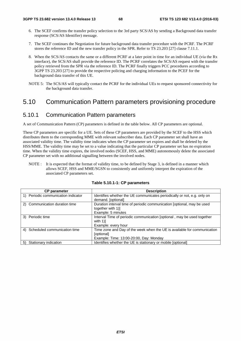
ETSI
ETSI TS 123 682 V13.4.0 (2016-03)683GPP TS 23.682 version 13.4.0 Release 13
6. The SCEF confirms the transfer policy selection to the 3rd party SCS/AS by sending a Background data transfer response (SCS/AS Identifier) message.
7. The SCEF continues the Negotiation for future background data transfer procedure with the PCRF. The PCRF stores the reference ID and the new transfer policy in the SPR. Refer to TS 23.203 [27] clause 7.11.1.
8. When the SCS/AS contacts the same or a different PCRF at a later point in time for an individual UE (via the Rx interface), the SCS/AS shall provide the reference ID. The PCRF correlates the SCS/AS request with the transfer policy retrieved from the SPR via the reference ID. The PCRF finally triggers PCC procedures according to 3GPP TS 23.203 [27] to provide the respective policing and charging information to the PCEF for the background data transfer of this UE.
NOTE 5: The SCS/AS will typically contact the PCRF for the individual UEs to request sponsored connectivity for the background data transfer.
5.10 Communication Pattern parameters provisioning procedure
5.10.1 Communication Pattern parameters
A set of Communication Pattern (CP) parameters is defined in the table below. All CP parameters are optional.
These CP parameters are specific for a UE. Sets of these CP parameters are provided by the SCEF to the HSS which distributes them to the corresponding MME with relevant subscriber data. Each CP parameter set shall have an associated validity time. The validity time indicates when the CP parameter set expires and shall be deleted by the HSS/MME. The validity time may be set to a value indicating that the particular CP parameter set has no expiration time. When the validity time expires, the involved nodes (SCEF, HSS, and MME) autonomously delete the associated CP parameter set with no additional signalling between the involved nodes.
NOTE : It is expected that the format of validity time, to be defined by Stage 3, is defined in a manner which allows SCEF, HSS and MME/SGSN to consistently and uniformly interpret the expiration of the associated CP parameters set.
Table 5.10.1-1: CP parameters
CP parameter Description 1) Periodic communication indicator Identifies whether the UE communicates periodically or not, e.g. only on
demand. [optional] 2) Communication duration time Duration interval time of periodic communication [optional, may be used
together with 1)] Example: 5 minutes
3) Periodic time Interval Time of periodic communication [optional , may be used together with 1)] Example: every hour
4) Scheduled communication time Time zone and Day of the week when the UE is available for communication [optional] Example: Time: 13:00-20:00, Day: Monday
5) Stationary indication Identifies whether the UE is stationary or mobile [optional]
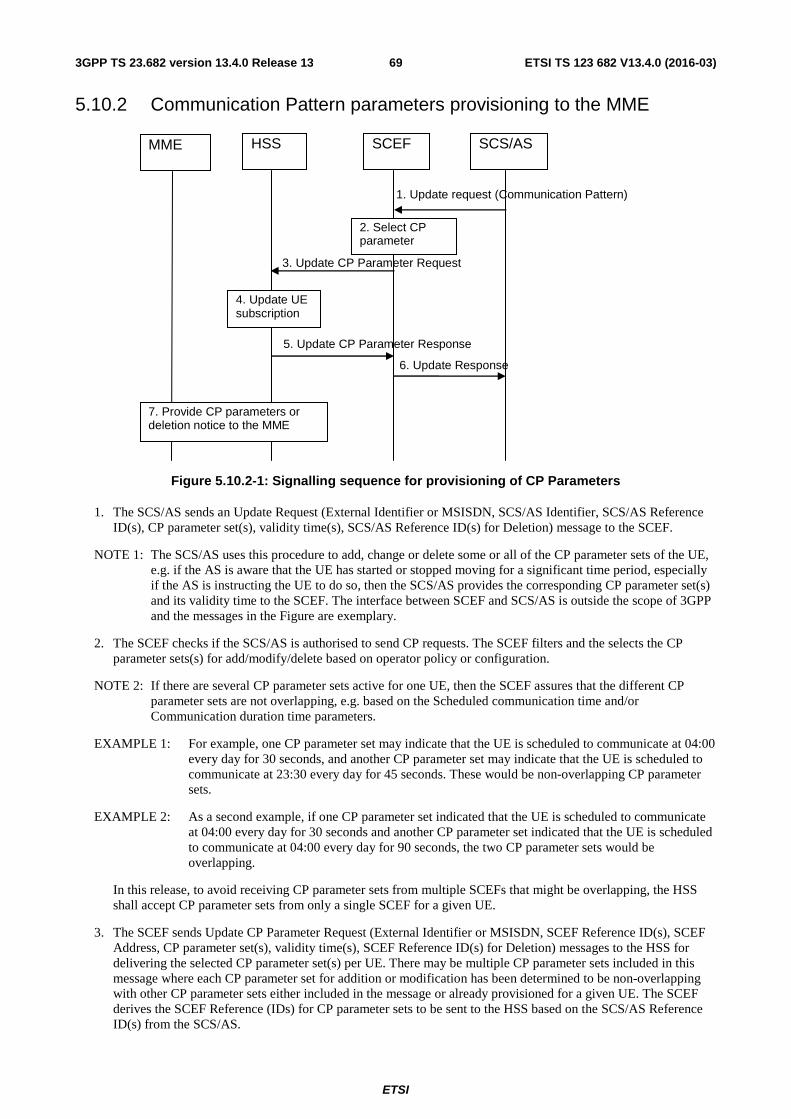
ETSI
ETSI TS 123 682 V13.4.0 (2016-03)693GPP TS 23.682 version 13.4.0 Release 13
5.10.2 Communication Pattern parameters provisioning to the MME
MME HSS SCEF SCS/AS
2. Select CP parameter
3. Update CP Parameter Request
5. Update CP Parameter Response
6. Update Response
7. Provide CP parameters or deletion notice to the MME
1. Update request (Communication Pattern)
4. Update UE subscription
Figure 5.10.2-1: Signalling sequence for provisioning of CP Parameters
1. The SCS/AS sends an Update Request (External Identifier or MSISDN, SCS/AS Identifier, SCS/AS Reference ID(s), CP parameter set(s), validity time(s), SCS/AS Reference ID(s) for Deletion) message to the SCEF.
NOTE 1: The SCS/AS uses this procedure to add, change or delete some or all of the CP parameter sets of the UE, e.g. if the AS is aware that the UE has started or stopped moving for a significant time period, especially if the AS is instructing the UE to do so, then the SCS/AS provides the corresponding CP parameter set(s) and its validity time to the SCEF. The interface between SCEF and SCS/AS is outside the scope of 3GPP and the messages in the Figure are exemplary.
2. The SCEF checks if the SCS/AS is authorised to send CP requests. The SCEF filters and the selects the CP parameter sets(s) for add/modify/delete based on operator policy or configuration.
NOTE 2: If there are several CP parameter sets active for one UE, then the SCEF assures that the different CP parameter sets are not overlapping, e.g. based on the Scheduled communication time and/or Communication duration time parameters.
EXAMPLE 1: For example, one CP parameter set may indicate that the UE is scheduled to communicate at 04:00 every day for 30 seconds, and another CP parameter set may indicate that the UE is scheduled to communicate at 23:30 every day for 45 seconds. These would be non-overlapping CP parameter sets.
EXAMPLE 2: As a second example, if one CP parameter set indicated that the UE is scheduled to communicate at 04:00 every day for 30 seconds and another CP parameter set indicated that the UE is scheduled to communicate at 04:00 every day for 90 seconds, the two CP parameter sets would be overlapping.
In this release, to avoid receiving CP parameter sets from multiple SCEFs that might be overlapping, the HSS shall accept CP parameter sets from only a single SCEF for a given UE.
3. The SCEF sends Update CP Parameter Request (External Identifier or MSISDN, SCEF Reference ID(s), SCEF Address, CP parameter set(s), validity time(s), SCEF Reference ID(s) for Deletion) messages to the HSS for delivering the selected CP parameter set(s) per UE. There may be multiple CP parameter sets included in this message where each CP parameter set for addition or modification has been determined to be non-overlapping with other CP parameter sets either included in the message or already provisioned for a given UE. The SCEF derives the SCEF Reference (IDs) for CP parameter sets to be sent to the HSS based on the SCS/AS Reference ID(s) from the SCS/AS.
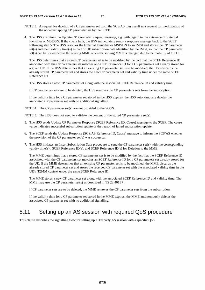
ETSI
ETSI TS 123 682 V13.4.0 (2016-03)703GPP TS 23.682 version 13.4.0 Release 13
NOTE 3: A request for deletion of a CP parameter set from the SCS/AS may result in a request for modification of the non-overlapping CP parameter set by the SCEF.
4. The HSS examines the Update CP Parameter Request message, e.g. with regard to the existence of External Identifier or MSISSN. If the check fails, the HSS immediately sends a response message back to the SCEF following step 5. The HSS resolves the External Identifier or MSISDN to an IMSI and stores the CP parameter set(s) and their validity time(s) as part of UE subscription data identified by the IMSI, so that the CP parameter set(s) can be forwarded to the serving MME when the serving MME is changed due to the mobility of the UE.
The HSS determines that a stored CP parameters set is to be modified by the fact that the SCEF Reference ID associated with the CP parameters set matches an SCEF Reference ID for a CP parameters set already stored for a given UE. If the HSS determines that an existing CP parameter set is to be modified, the HSS discards the already stored CP parameter set and stores the new CP parameter set and validity time under the same SCEF Reference ID.
The HSS stores a new CP parameter set along with the associated SCEF Reference ID and validity time.
If CP parameters sets are to be deleted, the HSS removes the CP parameters sets from the subscription.
If the validity time for a CP parameter set stored in the HSS expires, the HSS autonomously deletes the associated CP parameter set with no additional signalling.
NOTE 4: The CP parameter set(s) are not provided to the SGSN.
NOTE 5: The HSS does not need to validate the content of the stored CP parameters set(s).
5. The HSS sends Update CP Parameter Response (SCEF Reference ID, Cause) message to the SCEF. The cause value indicates successful subscription update or the reason of failed subscription update.
6. The SCEF sends the Update Response (SCS/AS Reference ID, Cause) message to inform the SCS/AS whether the provision of the CP parameter set(s) was successful.
7. The HSS initiates an Insert Subscription Data procedure to send the CP parameter set(s) with the corresponding validty time(s) , SCEF Reference ID(s), and SCEF Reference ID(s) for Deletion to the MME.
The MME determines that a stored CP parameters set is to be modified by the fact that the SCEF Reference ID associated with the CP parameters set matches an SCEF Reference ID for a CP parameters set already stored for the UE. If the MME determines that an existing CP parameter set is to be modified, the MME discards the already stored CP parameter set and stores the received CP parameter set with the associated validity time in the UE's (E)MM context under the same SCEF Reference ID.
The MME stores a new CP parameter set along with the associated SCEF Reference ID and validity time. The MME may use the CP parameter set(s) as described in TS 23.401 [7].
If CP parameter sets are to be deleted, the MME removes the CP parameter sets from the subscription.
If the validity time for a CP parameter set stored in the MME expires, the MME autonomously deletes the associated CP parameter set with no additional signalling.
5.11 Setting up an AS session with required QoS procedure This clause describes the signalling flow for setting up a 3rd party AS session with a specific QoS.
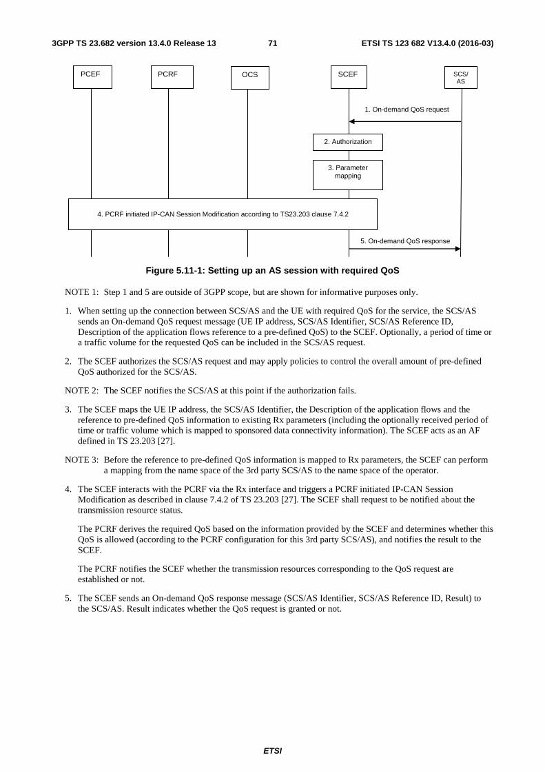
ETSI
ETSI TS 123 682 V13.4.0 (2016-03)713GPP TS 23.682 version 13.4.0 Release 13
PCEF PCRF SCEF
2. Authorization
1. On-demand QoS request
SCS/AS
OCS
5. On-demand QoS response
4. PCRF initiated IP-CAN Session Modification according to TS23.203 clause 7.4.2
3. Parameter mapping
Figure 5.11-1: Setting up an AS session with required QoS
NOTE 1: Step 1 and 5 are outside of 3GPP scope, but are shown for informative purposes only.
1. When setting up the connection between SCS/AS and the UE with required QoS for the service, the SCS/AS sends an On-demand QoS request message (UE IP address, SCS/AS Identifier, SCS/AS Reference ID, Description of the application flows reference to a pre-defined QoS) to the SCEF. Optionally, a period of time or a traffic volume for the requested QoS can be included in the SCS/AS request.
2. The SCEF authorizes the SCS/AS request and may apply policies to control the overall amount of pre-defined QoS authorized for the SCS/AS.
NOTE 2: The SCEF notifies the SCS/AS at this point if the authorization fails.
3. The SCEF maps the UE IP address, the SCS/AS Identifier, the Description of the application flows and the reference to pre-defined QoS information to existing Rx parameters (including the optionally received period of time or traffic volume which is mapped to sponsored data connectivity information). The SCEF acts as an AF defined in TS 23.203 [27].
NOTE 3: Before the reference to pre-defined QoS information is mapped to Rx parameters, the SCEF can perform a mapping from the name space of the 3rd party SCS/AS to the name space of the operator.
4. The SCEF interacts with the PCRF via the Rx interface and triggers a PCRF initiated IP-CAN Session Modification as described in clause 7.4.2 of TS 23.203 [27]. The SCEF shall request to be notified about the transmission resource status.
The PCRF derives the required QoS based on the information provided by the SCEF and determines whether this QoS is allowed (according to the PCRF configuration for this 3rd party SCS/AS), and notifies the result to the SCEF.
The PCRF notifies the SCEF whether the transmission resources corresponding to the QoS request are established or not.
5. The SCEF sends an On-demand QoS response message (SCS/AS Identifier, SCS/AS Reference ID, Result) to the SCS/AS. Result indicates whether the QoS request is granted or not.
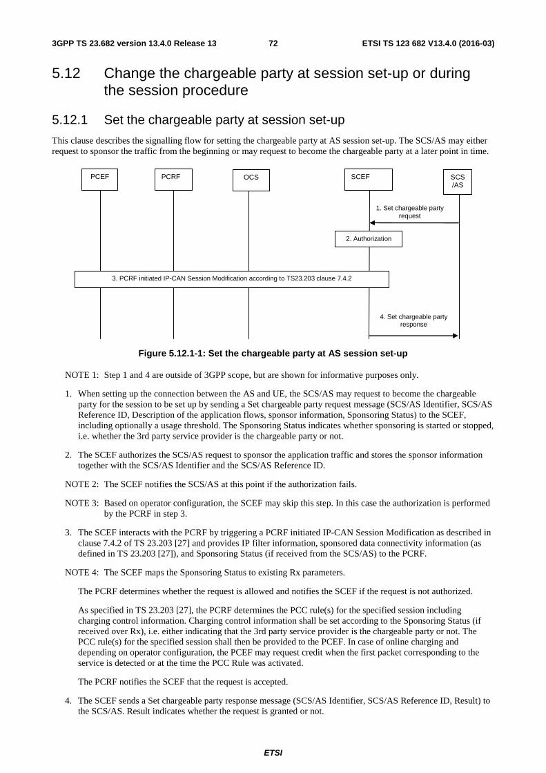
ETSI
ETSI TS 123 682 V13.4.0 (2016-03)723GPP TS 23.682 version 13.4.0 Release 13
5.12 Change the chargeable party at session set-up or during the session procedure
5.12.1 Set the chargeable party at session set-up
This clause describes the signalling flow for setting the chargeable party at AS session set-up. The SCS/AS may either request to sponsor the traffic from the beginning or may request to become the chargeable party at a later point in time.
PCEF PCRF SCEF
2. Authorization
1. Set chargeable party request
SCS/AS
OCS
4. Set chargeable party response
3. PCRF initiated IP-CAN Session Modification according to TS23.203 clause 7.4.2
Figure 5.12.1-1: Set the chargeable party at AS session set-up
NOTE 1: Step 1 and 4 are outside of 3GPP scope, but are shown for informative purposes only.
1. When setting up the connection between the AS and UE, the SCS/AS may request to become the chargeable party for the session to be set up by sending a Set chargeable party request message (SCS/AS Identifier, SCS/AS Reference ID, Description of the application flows, sponsor information, Sponsoring Status) to the SCEF, including optionally a usage threshold. The Sponsoring Status indicates whether sponsoring is started or stopped, i.e. whether the 3rd party service provider is the chargeable party or not.
2. The SCEF authorizes the SCS/AS request to sponsor the application traffic and stores the sponsor information together with the SCS/AS Identifier and the SCS/AS Reference ID.
NOTE 2: The SCEF notifies the SCS/AS at this point if the authorization fails.
NOTE 3: Based on operator configuration, the SCEF may skip this step. In this case the authorization is performed by the PCRF in step 3.
3. The SCEF interacts with the PCRF by triggering a PCRF initiated IP-CAN Session Modification as described in clause 7.4.2 of TS 23.203 [27] and provides IP filter information, sponsored data connectivity information (as defined in TS 23.203 [27]), and Sponsoring Status (if received from the SCS/AS) to the PCRF.
NOTE 4: The SCEF maps the Sponsoring Status to existing Rx parameters.
The PCRF determines whether the request is allowed and notifies the SCEF if the request is not authorized.
As specified in TS 23.203 [27], the PCRF determines the PCC rule(s) for the specified session including charging control information. Charging control information shall be set according to the Sponsoring Status (if received over Rx), i.e. either indicating that the 3rd party service provider is the chargeable party or not. The PCC rule(s) for the specified session shall then be provided to the PCEF. In case of online charging and depending on operator configuration, the PCEF may request credit when the first packet corresponding to the service is detected or at the time the PCC Rule was activated.
The PCRF notifies the SCEF that the request is accepted.
4. The SCEF sends a Set chargeable party response message (SCS/AS Identifier, SCS/AS Reference ID, Result) to the SCS/AS. Result indicates whether the request is granted or not.
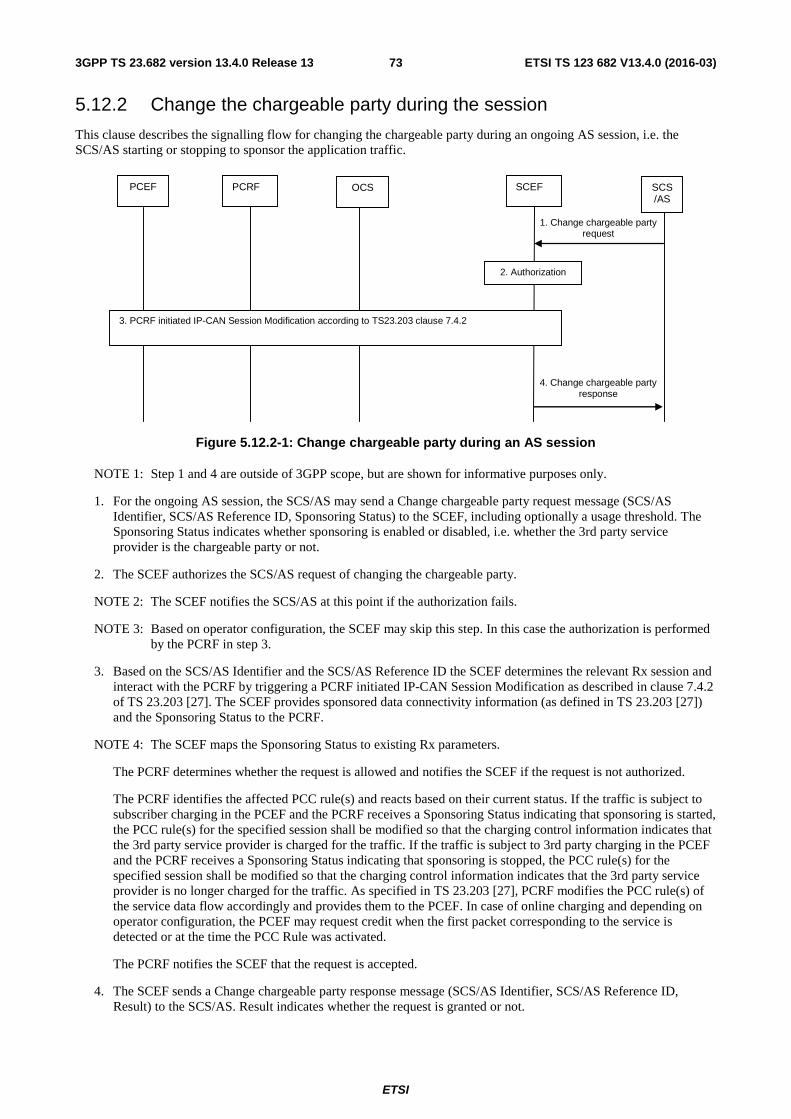
ETSI
ETSI TS 123 682 V13.4.0 (2016-03)733GPP TS 23.682 version 13.4.0 Release 13
5.12.2 Change the chargeable party during the session
This clause describes the signalling flow for changing the chargeable party during an ongoing AS session, i.e. the SCS/AS starting or stopping to sponsor the application traffic.
PCEF PCRF SCEF
2. Authorization
1. Change chargeable party request
SCS/AS
OCS
3. PCRF initiated IP-CAN Session Modification according to TS23.203 clause 7.4.2
4. Change chargeable party response
Figure 5.12.2-1: Change chargeable party during an AS session
NOTE 1: Step 1 and 4 are outside of 3GPP scope, but are shown for informative purposes only.
1. For the ongoing AS session, the SCS/AS may send a Change chargeable party request message (SCS/AS Identifier, SCS/AS Reference ID, Sponsoring Status) to the SCEF, including optionally a usage threshold. The Sponsoring Status indicates whether sponsoring is enabled or disabled, i.e. whether the 3rd party service provider is the chargeable party or not.
2. The SCEF authorizes the SCS/AS request of changing the chargeable party.
NOTE 2: The SCEF notifies the SCS/AS at this point if the authorization fails.
NOTE 3: Based on operator configuration, the SCEF may skip this step. In this case the authorization is performed by the PCRF in step 3.
3. Based on the SCS/AS Identifier and the SCS/AS Reference ID the SCEF determines the relevant Rx session and interact with the PCRF by triggering a PCRF initiated IP-CAN Session Modification as described in clause 7.4.2 of TS 23.203 [27]. The SCEF provides sponsored data connectivity information (as defined in TS 23.203 [27]) and the Sponsoring Status to the PCRF.
NOTE 4: The SCEF maps the Sponsoring Status to existing Rx parameters.
The PCRF determines whether the request is allowed and notifies the SCEF if the request is not authorized.
The PCRF identifies the affected PCC rule(s) and reacts based on their current status. If the traffic is subject to subscriber charging in the PCEF and the PCRF receives a Sponsoring Status indicating that sponsoring is started, the PCC rule(s) for the specified session shall be modified so that the charging control information indicates that the 3rd party service provider is charged for the traffic. If the traffic is subject to 3rd party charging in the PCEF and the PCRF receives a Sponsoring Status indicating that sponsoring is stopped, the PCC rule(s) for the specified session shall be modified so that the charging control information indicates that the 3rd party service provider is no longer charged for the traffic. As specified in TS 23.203 [27], PCRF modifies the PCC rule(s) of the service data flow accordingly and provides them to the PCEF. In case of online charging and depending on operator configuration, the PCEF may request credit when the first packet corresponding to the service is detected or at the time the PCC Rule was activated.
The PCRF notifies the SCEF that the request is accepted.
4. The SCEF sends a Change chargeable party response message (SCS/AS Identifier, SCS/AS Reference ID, Result) to the SCS/AS. Result indicates whether the request is granted or not.
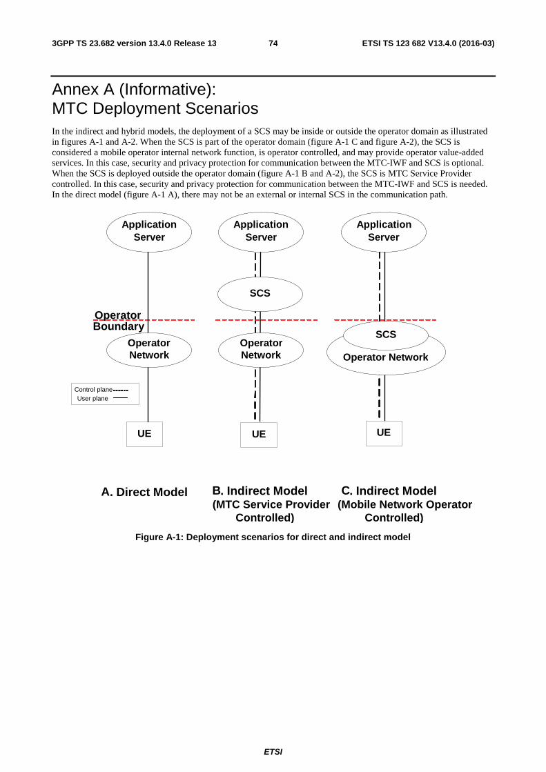
ETSI
ETSI TS 123 682 V13.4.0 (2016-03)743GPP TS 23.682 version 13.4.0 Release 13
Annex A (Informative): MTC Deployment Scenarios In the indirect and hybrid models, the deployment of a SCS may be inside or outside the operator domain as illustrated in figures A-1 and A-2. When the SCS is part of the operator domain (figure A-1 C and figure A-2), the SCS is considered a mobile operator internal network function, is operator controlled, and may provide operator value-added services. In this case, security and privacy protection for communication between the MTC-IWF and SCS is optional. When the SCS is deployed outside the operator domain (figure A-1 B and A-2), the SCS is MTC Service Provider controlled. In this case, security and privacy protection for communication between the MTC-IWF and SCS is needed. In the direct model (figure A-1 A), there may not be an external or internal SCS in the communication path.
Application
Server Application
Server Application
Server
Operator Network Operator Network
UE UE UE
SCS
SCS
Operator Boundary
A . Direct Model B . Indirect Model (MTC Service Provider
Controlled)
C . Indirect Model (Mobile Network Operator
Controlled)
Operator Network
Control plane User plane
Figure A-1: Deployment scenarios for direct and indirect model
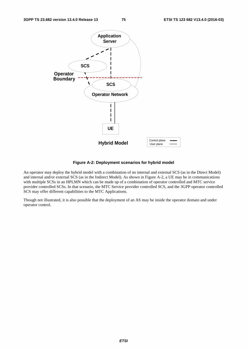
ETSI
ETSI TS 123 682 V13.4.0 (2016-03)753GPP TS 23.682 version 13.4.0 Release 13
Application Server
SCS
Operator Network
UE
Hybrid Model
SCS
Operator Boundary
Control plane User plane
Figure A-2: Deployment scenarios for hybrid model
An operator may deploy the hybrid model with a combination of no internal and external SCS (as in the Direct Model) and internal and/or external SCS (as in the Indirect Model). As shown in Figure A-2, a UE may be in communications with multiple SCSs in an HPLMN which can be made up of a combination of operator controlled and MTC service provider controlled SCSs. In that scenario, the MTC Service provider controlled SCS, and the 3GPP operator controlled SCS may offer different capabilities to the MTC Applications.
Though not illustrated, it is also possible that the deployment of an AS may be inside the operator domain and under operator control.
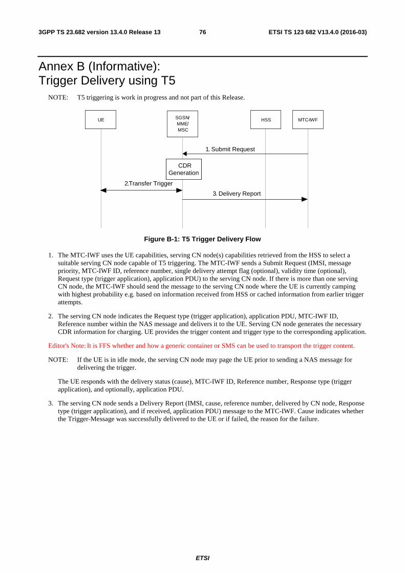
ETSI
ETSI TS 123 682 V13.4.0 (2016-03)763GPP TS 23.682 version 13.4.0 Release 13
Annex B (Informative): Trigger Delivery using T5
NOTE: T5 triggering is work in progress and not part of this Release.
UE HSS MTC -IWF
1 . Submit Request
3 . Delivery Report 2 .Transfer Trigger
SGSN / MME / MSC
CDR Generation
Figure B-1: T5 Trigger Delivery Flow
1. The MTC-IWF uses the UE capabilities, serving CN node(s) capabilities retrieved from the HSS to select a suitable serving CN node capable of T5 triggering. The MTC-IWF sends a Submit Request (IMSI, message priority, MTC-IWF ID, reference number, single delivery attempt flag (optional), validity time (optional), Request type (trigger application), application PDU) to the serving CN node. If there is more than one serving CN node, the MTC-IWF should send the message to the serving CN node where the UE is currently camping with highest probability e.g. based on information received from HSS or cached information from earlier trigger attempts.
2. The serving CN node indicates the Request type (trigger application), application PDU, MTC-IWF ID, Reference number within the NAS message and delivers it to the UE. Serving CN node generates the necessary CDR information for charging. UE provides the trigger content and trigger type to the corresponding application.
Editor's Note: It is FFS whether and how a generic container or SMS can be used to transport the trigger content.
NOTE: If the UE is in idle mode, the serving CN node may page the UE prior to sending a NAS message for delivering the trigger.
The UE responds with the delivery status (cause), MTC-IWF ID, Reference number, Response type (trigger application), and optionally, application PDU.
3. The serving CN node sends a Delivery Report (IMSI, cause, reference number, delivered by CN node, Response type (trigger application), and if received, application PDU) message to the MTC-IWF. Cause indicates whether the Trigger-Message was successfully delivered to the UE or if failed, the reason for the failure.
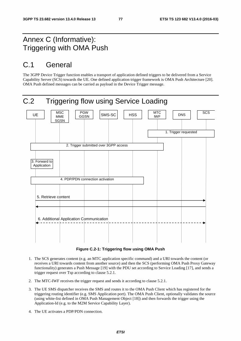
ETSI
ETSI TS 123 682 V13.4.0 (2016-03)773GPP TS 23.682 version 13.4.0 Release 13
Annex C (Informative): Triggering with OMA Push
C.1 General The 3GPP Device Trigger function enables a transport of application defined triggers to be delivered from a Service Capability Server (SCS) towards the UE. One defined application trigger framework is OMA Push Architecture [20]. OMA Push defined messages can be carried as payload in the Device Trigger message.
C.2 Triggering flow using Service Loading
UE MSC MME SGSN
PGW GGSN HSS
SCS DNS
5. Retrieve content
SMS-SC MTC IWF
4. PDP/PDN connection activation
3. Forward to Application
6. Additional Application Communication
2. Trigger submitted over 3GPP access
1. Trigger requested
Figure C.2-1: Triggering flow using OMA Push
1. The SCS generates content (e.g. an MTC application specific command) and a URI towards the content (or receives a URI towards content from another source) and then the SCS (performing OMA Push Proxy Gateway functionality) generates a Push Message [19] with the PDU set according to Service Loading [17], and sends a trigger request over Tsp according to clause 5.2.1.
2. The MTC-IWF receives the trigger request and sends it according to clause 5.2.1.
3. The UE SMS dispatcher receives the SMS and routes it to the OMA Push Client which has registered for the triggering routing identifier (e.g. SMS Application port). The OMA Push Client, optionally validates the source (using white-list defined in OMA Push Management Object [18]) and then forwards the trigger using the Application-Id (e.g. to the M2M Service Capability Layer).
4. The UE activates a PDP/PDN connection.
ETSI
ETSI TS 123 682 V13.4.0 (2016-03)783GPP TS 23.682 version 13.4.0 Release 13
5. The content described as part of the URI is retrieved (retrieval of content is mandatory for content type Service Loading [17]).
6. Based on the content retrieved the addressed Application may perform additional actions (e.g. the M2M Service Capability Layer may convey the information to an M2M Application addressed as part of the "command" retrieved, within the same or in a different physical device), but this is outside scope of 3GPP standardisation.
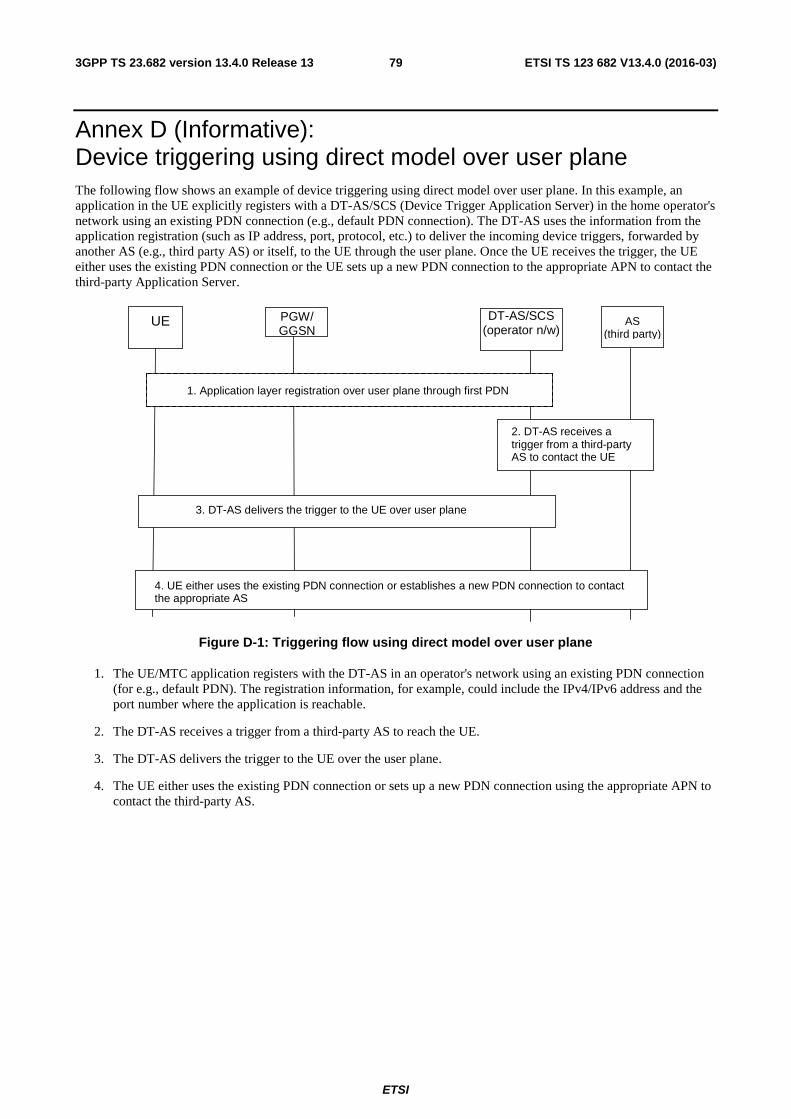
ETSI
ETSI TS 123 682 V13.4.0 (2016-03)793GPP TS 23.682 version 13.4.0 Release 13
Annex D (Informative): Device triggering using direct model over user plane The following flow shows an example of device triggering using direct model over user plane. In this example, an application in the UE explicitly registers with a DT-AS/SCS (Device Trigger Application Server) in the home operator's network using an existing PDN connection (e.g., default PDN connection). The DT-AS uses the information from the application registration (such as IP address, port, protocol, etc.) to deliver the incoming device triggers, forwarded by another AS (e.g., third party AS) or itself, to the UE through the user plane. Once the UE receives the trigger, the UE either uses the existing PDN connection or the UE sets up a new PDN connection to the appropriate APN to contact the third-party Application Server.
UE PGW/
GGSN DT-AS/SCS
(operator n/w)
2. DT-AS receives a trigger from a third-party AS to contact the UE
AS (third party)
3. DT-AS delivers the trigger to the UE over user plane
1. Application layer registration over user plane through first PDN
4. UE either uses the existing PDN connection or establishes a new PDN connection to contact the appropriate AS
Figure D-1: Triggering flow using direct model over user plane
1. The UE/MTC application registers with the DT-AS in an operator's network using an existing PDN connection (for e.g., default PDN). The registration information, for example, could include the IPv4/IPv6 address and the port number where the application is reachable.
2. The DT-AS receives a trigger from a third-party AS to reach the UE.
3. The DT-AS delivers the trigger to the UE over the user plane.
4. The UE either uses the existing PDN connection or sets up a new PDN connection using the appropriate APN to contact the third-party AS.
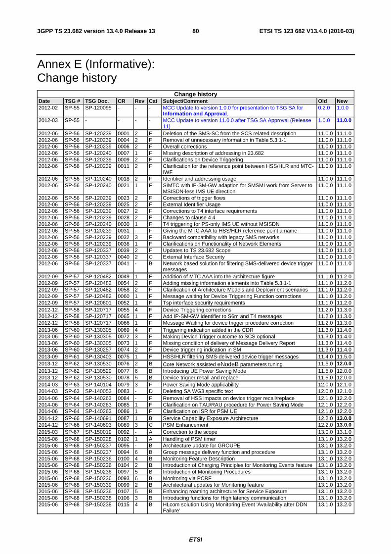
ETSI
ETSI TS 123 682 V13.4.0 (2016-03)803GPP TS 23.682 version 13.4.0 Release 13
Annex E (Informative): Change history
Change history Date TSG # TSG Doc. CR Rev Cat Subject/Comment Old New 2012-02 SP-55 SP-120095 - - - MCC Update to version 1.0.0 for presentation to TSG SA for
Information and Approval. 0.2.0 1.0.0
2012-03 SP-55 - - - - MCC Update to version 11.0.0 after TSG SA Approval (Release 11)
1.0.0 11.0.0
2012-06 SP-56 SP-120239 0001 2 F Deletion of the SMS-SC from the SCS related description 11.0.0 11.1.0 2012-06 SP-56 SP-120239 0004 2 F Removal of unnecessary information in Table 5.3.1-1 11.0.0 11.1.0 2012-06 SP-56 SP-120239 0006 2 F Overall corrections 11.0.0 11.1.0 2012-06 SP-56 SP-120240 0007 1 F Missing description of addressing in 23.682 11.0.0 11.1.0 2012-06 SP-56 SP-120239 0009 2 F Clarifications on Device Triggering 11.0.0 11.1.0 2012-06 SP-56 SP-120239 0011 2 F Clarification for the reference point between HSS/HLR and MTC-
IWF 11.0.0 11.1.0
2012-06 SP-56 SP-120240 0018 2 F Identifier and addressing usage 11.0.0 11.1.0 2012-06 SP-56 SP-120240 0021 1 F SIMTC with IP-SM-GW adaption for SMSMI work from Server to
MSISDN-less IMS UE direction 11.0.0 11.1.0
2012-06 SP-56 SP-120239 0023 2 F Corrections of trigger flows 11.0.0 11.1.0 2012-06 SP-56 SP-120239 0025 2 F External Identifier Usage 11.0.0 11.1.0 2012-06 SP-56 SP-120239 0027 2 F Corrections to T4 interface requirements 11.0.0 11.1.0 2012-06 SP-56 SP-120239 0028 2 F Changes to clause 4.4 11.0.0 11.1.0 2012-06 SP-56 SP-120240 0030 1 F T4 triggering for PS-only IMS UE without MSISDN 11.0.0 11.1.0 2012-06 SP-56 SP-120239 0031 - F Giving the MTC AAA to HSS/HLR reference point a name 11.0.0 11.1.0 2012-06 SP-56 SP-120239 0032 3 F Backward compatibility with legacy SMS networks 11.0.0 11.1.0 2012-06 SP-56 SP-120239 0036 1 F Clarifications on Functionality of Network Elements 11.0.0 11.1.0 2012-06 SP-56 SP-120337 0039 2 F Updates to TS 23.682 Scope 11.0.0 11.1.0 2012-06 SP-56 SP-120337 0040 2 C External Interface Security 11.0.0 11.1.0 2012-06 SP-56 SP-120337 0041 - B Network based solution for filtering SMS-delivered device trigger
messages 11.0.0 11.1.0
2012-09 SP-57 SP-120482 0049 1 F Addition of MTC AAA into the architecture figure 11.1.0 11.2.0 2012-09 SP-57 SP-120482 0054 2 F Adding missing information elements into Table 5.3.1-1 11.1.0 11.2.0 2012-09 SP-57 SP-120482 0058 2 F Clarification of Architecture Models and Deployment scenarios 11.1.0 11.2.0 2012-09 SP-57 SP-120482 0060 1 F Message waiting for Device Triggering Function corrections 11.1.0 11.2.0 2012-09 SP-57 SP-120601 0052 1 F Tsp interface security requirements 11.1.0 11.2.0 2012-12 SP-58 SP-120717 0055 4 F Device Triggering corrections 11.2.0 11.3.0 2012-12 SP-58 SP-120717 0065 1 F Add IP-SM-GW identifier to S6m and T4 messages 11.2.0 11.3.0 2012-12 SP-58 SP-120717 0066 1 F Message Waiting for device trigger procedure correction 11.2.0 11.3.0 2013-06 SP-60 SP-130305 0069 4 F Triggering indication added in the CDR 11.3.0 11.4.0 2013-06 SP-60 SP-130305 0072 3 F Making Device Trigger outcome to SCS optional 11.3.0 11.4.0 2013-06 SP-60 SP-130305 0073 1 F Missing condition of delivery of Message Delivery Report 11.3.0 11.4.0 2013-06 SP-60 SP-130257 0074 2 F Device triggering indication in SM 11.3.0 11.4.0 2013-09 SP-61 SP-130403 0075 1 F HSS/HLR filtering SMS-delivered device trigger messages 11.4.0 11.5.0 2013-12 SP-62 SP-130530 0076 2 B Core Network assisted eNodeB parameters tuning 11.5.0 12.0.0 2013-12 SP-62 SP-130529 0077 6 B Introducing UE Power Saving Mode 11.5.0 12.0.0 2013-12 SP-62 SP-130530 0078 5 B Device trigger recall and replace 11.5.0 12.0.0 2014-03 SP-63 SP-140104 0079 3 F Power Saving Mode applicability 12.0.0 12.1.0 2014-03 SP-63 SP-140053 0083 - D Deleting SA WG3 specific text 12.0.0 12.1.0 2014-06 SP-64 SP-140263 0084 - F Removal of HSS impacts on device trigger recall/replace 12.1.0 12.2.0 2014-06 SP-64 SP-140263 0085 1 F Clarification on TAU/RAU procedure for Power Saving Mode 12.1.0 12.2.0 2014-06 SP-64 SP-140263 0086 1 F Clarification on ISR for PSM UE 12.1.0 12.2.0 2014-12 SP-66 SP-140691 0087 1 B Service Capability Exposure Architecture 12.2.0 13.0.0 2014-12 SP-66 SP-140693 0089 3 C PSM Enhancement 12.2.0 13.0.0 2015-03 SP-67 SP-150019 0092 - A Correction to the scope 13.0.0 13.1.0 2015-06 SP-68 SP-150228 0102 1 A Handling of PSM timer 13.1.0 13.2.0 2015-06 SP-68 SP-150237 0095 - B Architecture update for GROUPE 13.1.0 13.2.0 2015-06 SP-68 SP-150237 0094 6 B Group message delivery function and procedure 13.1.0 13.2.0 2015-06 SP-68 SP-150236 0100 4 B Monitoring Feature Description 13.1.0 13.2.0 2015-06 SP-68 SP-150236 0104 2 B Introduction of Charging Principles for Monitoring Events feature 13.1.0 13.2.0 2015-06 SP-68 SP-150236 0097 5 B Introduction of Monitoring Procedures 13.1.0 13.2.0 2015-06 SP-68 SP-150236 0093 6 B Monitoring via PCRF 13.1.0 13.2.0 2015-06 SP-68 SP-150339 0099 2 B Architectural updates for Monitoring feature 13.1.0 13.2.0 2015-06 SP-68 SP-150236 0107 5 B Enhancing roaming architecture for Service Exposure 13.1.0 13.2.0 2015-06 SP-68 SP-150238 0106 3 B Introducing functions for High latency communication 13.1.0 13.2.0 2015-06 SP-68 SP-150238 0115 4 B HLcom solution Using Monitoring Event 'Availability after DDN
Failure' 13.1.0 13.2.0
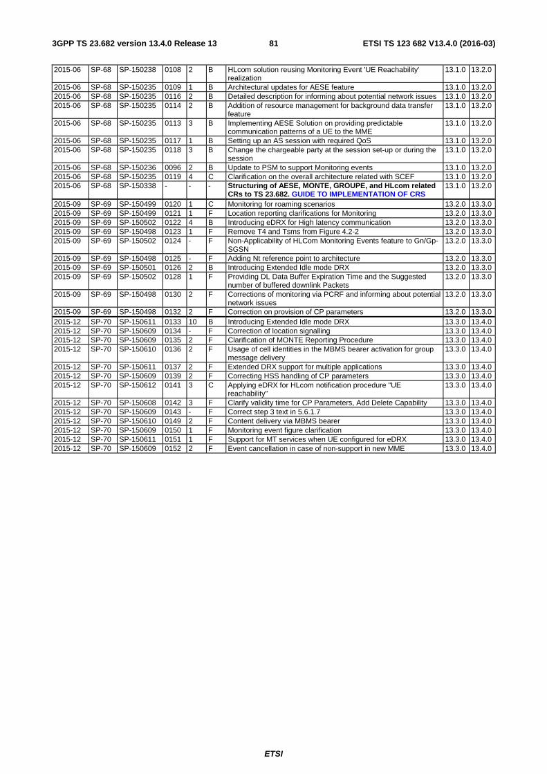
ETSI
ETSI TS 123 682 V13.4.0 (2016-03)813GPP TS 23.682 version 13.4.0 Release 13
2015-06 SP-68 SP-150238 0108 2 B HLcom solution reusing Monitoring Event 'UE Reachability' realization
13.1.0 13.2.0
2015-06 SP-68 SP-150235 0109 1 B Architectural updates for AESE feature 13.1.0 13.2.0 2015-06 SP-68 SP-150235 0116 2 B Detailed description for informing about potential network issues 13.1.0 13.2.0 2015-06 SP-68 SP-150235 0114 2 B Addition of resource management for background data transfer
feature 13.1.0 13.2.0
2015-06 SP-68 SP-150235 0113 3 B Implementing AESE Solution on providing predictable communication patterns of a UE to the MME
13.1.0 13.2.0
2015-06 SP-68 SP-150235 0117 1 B Setting up an AS session with required QoS 13.1.0 13.2.0 2015-06 SP-68 SP-150235 0118 3 B Change the chargeable party at the session set-up or during the
session 13.1.0 13.2.0
2015-06 SP-68 SP-150236 0096 2 B Update to PSM to support Monitoring events 13.1.0 13.2.0 2015-06 SP-68 SP-150235 0119 4 C Clarification on the overall architecture related with SCEF 13.1.0 13.2.0 2015-06 SP-68 SP-150338 - - - Structuring of AESE, MONTE, GROUPE, and HLcom related
CRs to TS 23.682. GUIDE TO IMPLEMENTATION OF CRS 13.1.0 13.2.0
2015-09 SP-69 SP-150499 0120 1 C Monitoring for roaming scenarios 13.2.0 13.3.0 2015-09 SP-69 SP-150499 0121 1 F Location reporting clarifications for Monitoring 13.2.0 13.3.0 2015-09 SP-69 SP-150502 0122 4 B Introducing eDRX for High latency communication 13.2.0 13.3.0 2015-09 SP-69 SP-150498 0123 1 F Remove T4 and Tsms from Figure 4.2-2 13.2.0 13.3.0 2015-09 SP-69 SP-150502 0124 - F Non-Applicability of HLCom Monitoring Events feature to Gn/Gp-
SGSN 13.2.0 13.3.0
2015-09 SP-69 SP-150498 0125 - F Adding Nt reference point to architecture 13.2.0 13.3.0 2015-09 SP-69 SP-150501 0126 2 B Introducing Extended Idle mode DRX 13.2.0 13.3.0 2015-09 SP-69 SP-150502 0128 1 F Providing DL Data Buffer Expiration Time and the Suggested
number of buffered downlink Packets 13.2.0 13.3.0
2015-09 SP-69 SP-150498 0130 2 F Corrections of monitoring via PCRF and informing about potential network issues
13.2.0 13.3.0
2015-09 SP-69 SP-150498 0132 2 F Correction on provision of CP parameters 13.2.0 13.3.0 2015-12 SP-70 SP-150611 0133 10 B Introducing Extended Idle mode DRX 13.3.0 13.4.0 2015-12 SP-70 SP-150609 0134 - F Correction of location signalling 13.3.0 13.4.0 2015-12 SP-70 SP-150609 0135 2 F Clarification of MONTE Reporting Procedure 13.3.0 13.4.0 2015-12 SP-70 SP-150610 0136 2 F Usage of cell identities in the MBMS bearer activation for group
message delivery 13.3.0 13.4.0
2015-12 SP-70 SP-150611 0137 2 F Extended DRX support for multiple applications 13.3.0 13.4.0 2015-12 SP-70 SP-150609 0139 2 F Correcting HSS handling of CP parameters 13.3.0 13.4.0 2015-12 SP-70 SP-150612 0141 3 C Applying eDRX for HLcom notification procedure "UE
reachability" 13.3.0 13.4.0
2015-12 SP-70 SP-150608 0142 3 F Clarify validity time for CP Parameters, Add Delete Capability 13.3.0 13.4.0 2015-12 SP-70 SP-150609 0143 - F Correct step 3 text in 5.6.1.7 13.3.0 13.4.0 2015-12 SP-70 SP-150610 0149 2 F Content delivery via MBMS bearer 13.3.0 13.4.0 2015-12 SP-70 SP-150609 0150 1 F Monitoring event figure clarification 13.3.0 13.4.0 2015-12 SP-70 SP-150611 0151 1 F Support for MT services when UE configured for eDRX 13.3.0 13.4.0 2015-12 SP-70 SP-150609 0152 2 F Event cancellation in case of non-support in new MME 13.3.0 13.4.0

ETSI
ETSI TS 123 682 V13.4.0 (2016-03)823GPP TS 23.682 version 13.4.0 Release 13
History
Document history
V13.4.0 March 2016 Publication


![09 UTRAN-procedures JMu.ppt [Kompatibilitätsmodus] · PDF fileUE Nd BNode B Nd B RNC RNC CN 1.1 Node B 2.1 1 2 RANAP RANAP 1. Paging RANAP RANAP 1. ... HO from UTRAN Command Relocation](https://static.fdocuments.net/doc/165x107/5a9df93e7f8b9ada718bf618/09-utran-procedures-jmuppt-kompatibilittsmodus-ue-nd-bnode-b-nd-b-rnc-rnc-cn.jpg)