TrustSight Gen2 LED Emergency Kit · 2019-08-15 · or maintained solution, designed to operate LED...
35
Design-in Guide TrustSight Gen2 LED Emergency Kit August 2019 TrustSight Emergency kit
Transcript of TrustSight Gen2 LED Emergency Kit · 2019-08-15 · or maintained solution, designed to operate LED...

Design-in Guide
TrustSight Gen2LED Emergency Kit
August 2019
TrustSight
Emergency kit

2 Design-in Guide - TrustSight Emergency Driver August 2019
Contents
Introduction to this guide 3Applications 3Information and support 3Design-in support 3Determine which documents contain what information 3
Safety precautions 4Safety warnings and installation instructions 4
Introduction to the TrustSight Emergency Driver 5Introduction 5Non-maintained 5Maintained 5Sustained 5TrustSight emergency versions 6Batteries 6Self-Test 7Self-test DALI driver 7Setting a standard driver to Australian mode 8Mechanical drawing of 2500 mAh battery 9Mechanical drawing of 3000 mAh battery 9Mechanical drawing of independent battery housing 10Mechanical drawing of 1300 mAh battery 10Features 11LED status indicator 11Test switch 12Automatic emergency time selection 12
Electrical design-in 13Short introduction into High- and Low voltage systems 13How to Configure a LV system in combination with a EM system 14How to Configure a HV system in combination with an EM system 14
Basic connection scheme 15Point source emergency driver 15Linear HV emergency driver 15Other examples of Linear HV systems 16In parallel 16Other examples of Linear LV systems 17The amount of light in Emergency mode 18More lumen in emergency mode 18Longer light output in emergency mode 18In Series 18Example 1 19Example 2 19Example 3 20Example 4 21Example 5 22How to… Wire – general remarks 23Electromagnetic compatibility (EMC) 23How to… Improve EMC performance 24
2425252525
2626262727272727
282828282929
30
323233333333
Improvement in EMC Performance Electrical insulation and protective earth Surge protection Touch current Insulation
Mechanical design-in LinearPointPoint with stain relief Loop through TrustSight point mains side connections Indicator LED Switch
Thermal design-in Case Temperature Point (Tc point) To measure Tc at the Tc point Relation between Tc and ambient temperature Battery storage temperature Battery operating temperature
ControllabilityDALI
Quality and Reliability LifetimeBattery installation at OEM Mains voltage fluctuations Low mains voltage High mains voltage
Disclaimer 34
30

3August 2019 Design-in Guide - TrustSight Emergency Driver
Introduction to this guide
Thank you for choosing the Philips TrustSight Emergency driver (EM). In this guide you will find the information needed to integrate an emergency driver into a LED luminaire or LED system. This design-in guide describes the TrustSight LED Emergency kit developed for indoor lighting applications. We advise you to consult our websites for the latest up-to-date information.
ApplicationsTypical applications are linear or point source type of luminaires applied in: offices, public buildings, industrial and retail environments.
Information and supportPlease consult your local Philips office or visit: www.philips.com/technology
Design-in supportOn request Design-in support from Philips is available. For this service please contact your Philips sales representative.
Determine which documents contain what informationIn order to provide information in the best possible way, Philips’ philosophy on product documentation is the following.• Commercial leaflet contains product family
information & system combinations• Datasheet contains the product specific specifications• Design-in guide describes how the product is to be
designed-in
All these documents can be found on the download page of the OEM website www.philips.com/technology. If you require any further information or support please consult your local Philips office.
Philips TrustSight Emergency driver (EM)
Product
information
Datasheet
Commercial leaflet Design-in Guide

4 Design-in Guide - TrustSight Emergency Driver August 2019
Safety precautions
• Do not use damaged products
• The luminaire manufacturer is responsible for its ownluminaire design and compliance with all relevant safetystandards including minimum required IP rating to protectthe driver.
• The TrustSight Emergency drivers must be protectedagainst ingress of and exposure to including but not limitedto snow, water, ice, dust, insects or any other chemicalagent - be it in the gaseous, vapor, liquid or solid form- which can be expected to have an adverse effect on thedriver (e.g. use in wet /corrosive / dusty environments). It isthe responsibility of both luminaire manufacturer andinstaller to prevent ingress and exposure. Any suggestionfrom Philips with reference to minimum required luminaireIP rating serves only as non-binding guidance; a higher IPrating may be required under certain application conditionsto protect the driver. Common sense needs to be used inorder to define the proper luminaire IP rating for theintended application.
• Do not service the driver when mains voltage isconnected; this includes connecting or disconnecting theLED module. The driver generates an output voltagewhich may be lethal. Connecting a LED module to anenergized driver may damage both the LED module anddriver.
• No components are allowed between the LED driverand the LED module(s) other than connectors andwiring intended to connect the Xitanium driver tothe LED module.
• Adequate earth and/or equipotential connections needsto be provided whenever possible or applicable.
• The TrustSight low-voltage SELV driver does not supportoperation combined with non-SELV AC-powered drivers.
• The TrustSight drivers are not intended for use in high risktask areas.
• The battery wires currently do not support independentoperation with respect to compliance per IEC60598-2 clause22.16 unless a fire and heat resistant supplementaryinsulation sleeve is put around the wires (not included). It isthe responsibility of the OEM to select the proper type ofsleeve.
• Philips Design-in support is available; please contactyour Philips sales representative.
Safety warnings:• Avoid touching live parts!• Do not use drivers with damaged housing and/or
connectors!• Do not service the driver when the mains voltage is
connected; this includes connecting or disconnecting theLED module!
Important installation instructions

5August 2019 Design-in Guide - TrustSight Emergency Driver
Introduction to the TrustSight Emergency Driver
IntroductionThe TrustSight LED Emergency kit is a self-contained and/or maintained solution, designed to operate LED modules in case of a mains power failure. An un-switched mains line is used to continuously charge TrustSight batteries and keep them in a state of readiness. At the same time the un-switched mains line is being monitored in order to detect mains power failure. When this happens, the TrustSight LED Emergency LED driver uses the TrustSight battery as energy source and provides power to (a part of) the LED array.
Non-maintainedA non-maintained luminaire only operates when mains power fails, in case the power failure the non-maintained luminaire will start-up on battery supply at 3 or 6 W depending on driver type.• Example scheme
Point non-maintained
MaintainedA maintained luminaire is designed to be lit continuously and will continue to work, even in the event of a power failure the TrustSight driver will switch the connected LED module to the battery supply.
Point maintained
SustainedThis is an exit or emergency luminaire with two or more lamps where at least one lamp operates in non-maintained mode and is only illuminated when normal supply fails. The other lamp operates on the normal supply only. This is identical in functionality to having a Non-Maintained Luminaire and a Normal Luminaire both in the same housing. Sustained Luminaires have two line inputs. One is connected to the Normal lighting output of the load controller. The Sustained input is connected to the load side of the load controllers circuit breaker, which supplies power to charge the internal battery and to use as a signal to turn the lamp on in the event of a power failure.
+ -
IndicatorLED
Unswitched line
SWL Battery +
Controlgear + 1
2
3
4
5
6
7
8
9
10
6
5
4
3
2
1
Controlgear -
LED module +
LED module -
Test Switch
Test Switch
Battery -
LED RD
LED GN
TrustSight Point 15...55 V(LED Emergency Driver Gen2)
SWN
SWL
SWN
L
N
LED-module(Emergency)
Unswitched Neutral
Neutral
Out+
+ -
Out-Point LED driver
IndicatorLED
Line
Unswitched line
SWL Battery +
Controlgear + 1
2
3
4
5
6
7
8
9
10
6
5
4
3
2
1
Controlgear -
LED module +
LED module -
Test Switch
Test Switch
Battery -
LED RD
LED GN
TrustSight Point 15...55 V(LED Emergency Driver Gen2)
SWN
SWL
SWN
N
L
LED-module(Emergency)
Unswitched Neutral

6 Design-in Guide - TrustSight Emergency Driver August 2019
TrustSight emergency versions
Batteries
ConnectionThe batteries are supplied with short (± 8 cm) cables (AWG22) with Molex 5557-series connector. Together with the emergency driver and batteries, a battery harness is shipped, which has two flying leads on one end and a Molex 5556 series connector on the other end. The insulation class of the battery is basic.
ChargingAfter first installation (and after each emergency mode operation), the batteries need to be charged for at least 24 hours to become sufficiently charged again. If the battery is not completely discharged the required charge time is shorter accordingly. The status of the battery is given by the indicator LED.
Periodic testingPeriodic tests should be performed according to EN 50172:2004, clause 7.2.3 and 7.2.4. monthly, switch on in the emergency mode by simulation of a failure of the supply to the normal lighting for a period sufficient to ensure that each lamp is illuminated. Annually, each luminaire shall be tested for its full rated duration (at least 1hr or 3hrs (depending on product installed)).
Warning:- The battery wires currently do not support independentoperation with respect to compliance per IEC60598-2 clause22.16 unless a fire and heat resistant supplementary insulationsleeve is put around the wires (not included). It is theresponsibility of the OEM to select the proper type of sleeve.
Linear
Product description 12NC Pieces per box
TrustSight Basic L 20-95V 3W 9137 007 67366 10
TrustSight Pro L 20-95V 3W 9137 007 66766 10
TrustSight DALI L 20-95V 3W 9290 009 95966 10
TrustSight Basic L 20-95V 6W 9137 007 67466 10
TrustSight Pro L 20-95V 6W 9137 007 66866 10
TrustSight DALI L 20-95V 6W 9290 009 96066 10
Point
Product description 12NC Pieces per box
TrustSight Basic P 15-55V 3W 9137 007 67266 10
TrustSight Pro P 15-55V 3W 9137 007 66666 10
TrustSight DALI P 15-55V 3W 9290 009 95866 10
Batteries
Product description 12NC Pieces per box
TrustSight Batt Box NiMH 7.2V 1300mA 9137 007 68166 10
TrustSight Batt Box NiMH 7.2V 2500mAh 9137 007 68266 10
TrustSight Batt Box NiMH 7.2V 3000mAh 9290 015 72466 10
TrustSight Battery Pack independent Housing 9290 009 97606 10

7August 2019 Design-in Guide - TrustSight Emergency Driver
Self-TestThe TrustSight Pro versions are equipped with a self-test functionality according IEC 62034. At 28 days after power-up the TrustSight will perform a functional test of 30 seconds. Every 6th test (after half year) will be a duration test. This test will run until the battery is empty and it will check if the capacity of the battery is sufficient to provide 1hr or 3hrs emergency time for respectively a 1hr or 3hrs system. This will result in 2 full duration tests every year.
During the tests the battery and output is checked. During the duration test also the battery capacity is checked. In case of a failure, an error will be indicated by the indicator LED. When scheduling a test (functional or duration test) the operation of the AC-driver is also checked. When the AC-driver is active, so normal lighting is on, the test will be postponed for a maximum of 3 days. When the AC-driver is off for at least 1 hour the test is started. The functional and duration test can only be started when the battery is fully charged
Self-test DALI driverDuration test (DT) and functional test (FT) default interval. Duration Test Interval Time can be set at “0”, disabling the duration tests. This means that there will be no Duration Tests initiated by the TrustSight DALI drivers. The Duration tests must be initiated by ATS (lighting management system). The TrustSight does have the automatic battery detection feature. This feature will initiate a DT once, after power up and when the battery is fully charged (after 24hrs). At the end of this DT the battery type is set in the driver and the TrustSight drivers will recognize it as an 1hr or 3hr driver by MultiOne (or other DALI tool). When this DT fails (e.g. mains is disconnected during the test) there will not be a new DT initiated and the TrustSight driver is not defined as 1hr or 3hr driver. To define the battery type the end user/installer should initiate a DT manually when the “Duration Test Interval Time” is set at “0”.

8 Design-in Guide - TrustSight Emergency Driver August 2019
LifetimeThe batteries have a life time expectancy of 4 years when maintained properly, as shown in the table below
Shelf lifeThe NiMH batteries will be charged before shipment and need to be used before the date indicated on the battery (packing) due to self-discharging when stored at Tstore ≤ 30 °C.
Initially the battery is charged with a constant current, according to the manufacturer’s specification. After 24 hours the battery will be fully charged and the charger will switch over to pulse-charging to keep the battery fully charged. The pulse charge scheme is given in the picture to the left.
Setting a standard driver to Australian modeBecause in Australia the charge and discharge timing is different the driver needs to be set in specific mode. To change to this mode the test-button can be used. Morse code is used to convert a standard driver to Australia mode. Please contact your local Philips representative for more information.
Procedure:The test switch short pressing (less than 2 sec)represents a Dit(.)and a test switch long pressing (less than 4 sec but more than 2 sec) represents a Dah(_). So the trigger sequence is “. _ . . _ . . . “.When Australia mode triggered, the LED indicator will flash red fast (about 5s) before it flashes green slowly (in charging process).
5 seconds time out for input sequence. That means if the period of no input is more than 5s, the current input sequence will be aborted. Pressing test switch more than 60s to quit Australia mode. When Australia mode is cleared, the LED indicator will flash red fast (about 5s) before it flashes green slowly (in charging process).
For convenience of installer, pressing test switch more than 60s, will not trigger a duration test. If Australia mode triggered, when driver is powered on, the LED indicator will flash red once before it flashes green slowly (in charging process).
Item Technical Data International standards Clauses
Cells intended for permanent
charge at elevated temperature
Yes IEC 61-951-2 (ex IEC61436 §7.2
IEC 61-951-2 (ex IEC61436 §7.2
§7.4.2.3 and 7.9
Expected operation life under folowing conditions
Maximum continuous temperature
Maximum occasional temperature
Discharge
> 4 years
+ 50 °C (55C @charging)
+ 65 °C (1 month)
1 discharge per year (minimum
requirement)
Note: Pro- and DALI version will have
(automatically) 2 discharges per year
Recommend charge method
Ch
arge
cu
rre
nt
50 ˚C
0.00C
0.05C
0 30 min 30 min 30 min
5 min24 hours 5 min 5 min
Continuerecycle

9August 2019 Design-in Guide - TrustSight Emergency Driver
Mechanical drawing of 2500 mAh battery
Mechanical drawing of 3000 mAh battery
200±10 129±2 50±10 129±2
4
150±2
4 1 24 3
5 5
22.5
±0.5
24±1
Parts List
Item Quantity Part number Description
1 1 PCB material CEM1 (no copper)
2 6 Cell H-SC2500BT 42.4*22.2
3 1 Battery/PCB insulator wrap
4 1 Connector + Wire (red/black)
5 1 Label
200±10 215±2 50±10 215±2
4
240±2
4 1 24 3
5
18.5
±0.5
20±1
Parts List
Item Quantity Part number Description
1 1 Plastic
2 6 Cell H-18700 70*18
3 1 Battery/PCB Insulation wrap
4 1 Connector + Wire (red/black)
5 1 Label
Dimensions in mm.

10 Design-in Guide - TrustSight Emergency Driver August 2019
Mechanical drawing of independent battery housing
187
5429
198
Mechanical drawing of 1300 mAh battery
150 MAX
30.5
MA
X
30.5
MA
X
17.5 MAX
16
158
170

11August 2019 Design-in Guide - TrustSight Emergency Driver
Features• Constant output power• Small, low profile batteries• Loop “wire” through capability switched mains wires for
point driver• Compatible with all dimmable and non-dimmable
constant current LED control gear- The maximum allowed output current rating of the
associated LED control gear is 2.0 A peak (current ratingof switching relays of TrustSight emergency driver)
- The maximum allowed LED load voltage on the outputterminals of the TrustSight emergency driver output is60 V in case of the point driver and 110 V for the lineardriver.
• Over-voltage protected LED output• Short circuit proof LED output and battery connection• Battery polarity reversal protection• Deep discharge protection
LED status indicatorThe LED status indicator shows whether:• The system is in charging mode• Batteries are fully charged• A system error has occurred
See also overview table in chapter quality This LEDstatus indicator will have the same response for theBasic, Pro and DALI version
LED indicator status
LED indicator (colour / flashing) Error condition Cause Solution
Green / no flashing System OK, battery fully charged
Green / slow (0.25s on, 1.25s off) System OK, battery is charging
Green / fast (0.25s on, 0.25s off) System OK, recently tested (< 5 days)
Red / no flashing Battery voltage too high No battery connected Connect a battery
Red / no flashing Battery voltage too low Wrong or bad battery connected Replace battery
Red / fast (0.25s on, 0.25s off) Output voltage too low Wrong LED load connected Connect a right load and perform a
functional test by pressing the switch
>5 s and <10 s
Red / fast (0.25s on, 0.25s off) Output voltage too high Wrong LED load connected Connect a right load and perform a
functional test by pressing the switch
>5 s and <10 s
Red / slow (0.25s on, 1.25s off) Failed test due to battery Battery end of life Replace battery and perform a duration test.
Fast flashing: (on-time = 0.25s, off-time = 0.25s) Slow flashing: (on-time = 0.25s, off-time = 1.25s) Warning:
• Do not exceed 2m cable length between TrustSightdriver and LED status indicator.
• Do not combine a single LED status indicator withmultiple TrustSight drivers. Each driver must have itsown LED status indicator.
• Independent use: the LED status indicator wiresmust have an additional supplementary insulationsleeve when used with a non-SELV AC LED driver.
Off Mains off, EM mode, Rest mode, test in progress
Green / short (50ms on, 0.95s off)

12 Design-in Guide - TrustSight Emergency Driver August 2019
Test switchAn optional test switch can be connected to the TrustSight emergency driver. This can be used to:• Initiate functional test as long as switch pressed:
press 0 < time < 10 s• The previous error (if present) will be cleared if the swich
is pressed >5 s and <10 s.• Initiate duration test: press > 10 s• In manual test mode, the battery and LED load will be
checked. If any error occurs, corresponding error bit (forDALI drivers) will be set and the TrustSight will go intocharge mode regardless of the test button pressing.
• Pressing the test button in Emergency mode or during aself-test mode will not have any effect.
Automatic emergency time selectionPhilips TrustSight emergency drivers are equipped with an automatic battery detection feature. At shipment, the emergency driver is not defined as a 1hr or 3hrs version. The procedure for automatic battery detection is as follows:
• After installation the driver will charge the batteryfor 24hrs.
• After 24hrs a duration test will be performed.• At the end of the duration test the TrustSight will set the
battery type and will charge the battery again until it isfully charged. This only applies for the 3W version. The6W version is only available as a 1hr version . This 6WTrustSight driver is already configurated in the factory.
After that, the system is defined and fully operational. The battery type definition has influence on the performance during the self-test and on the battery charge method. When the automatic battery detection process is disrupted, e.g. by switching off the permanent mains, the detection process is stopped and the TrustSight emergency driver will go into emergency mode. At a next power up, the automatic detection process will start again with 24h charging.
1 hour and 3 hours emergency time
Specification item Type Condition
3 W NiMH 1300 mAh AA-Cells 1 hour rate duration
3 W or 6 W NiMH 2500 mAh sC-Cells 1 or 3 hours rate duration
3 W or 6 W NiMH 3000mAh 18700 Cells 1 or 3 hours rate duration
Warning:• Do not exceed 2m cable length between TrustSight driver
and test switch.• Do not combine a single test switch with multiple TrustSight
drivers. Each driver must have its own test switch.• Independent use: the test switch wires must have an
additional supplementary insulation sleeve when used witha non-SELV AC LED driver.

13August 2019 Design-in Guide - TrustSight Emergency Driver
Electrical design-in
Short introduction into High- and Low voltage systemsLow voltage system Low Voltage (LV) systems typically use LV LED modules or Hybrid LED modules suitable for LV usage, connected to an isolated driver. LV products make a parallel system; adding a LED module requires a higher current.The majority of the LV systems are point source systems which can be installed outside the luminaire (in-depended) or build-in the luminaire
High voltage system High Voltage (HV) systems typically use HV LED modules or Hybrid LED modules suitable for HV usage, connected to a non-isolated driver. HV products make a series system; adding a LED module requires a higher voltage. The majority of the HV systems are build-in linear systems
Warning• Avoid touching live parts• Avoid touching any bare components on the PCB,
e.g, LEDs!• Do not use damage LED modules!
i
Warning• Avoid touching live parts• Avoid touching any bare components on the PCB,
e.g, LEDs!• Do not use damage LED modules!• Class 1 luminaires must be connected to protective
earth!
i
IN
+ +
-- LV LED module
OUT IN
+ +
-- LV LED module
OUT
Schematic representation of the wiring of 2 connected LV LED modules in an LV system, not needing a Return-End cable
Idrive = Inom [A] x # modules
Required drive current equals nominal current ofone LED module times number of LED modules.
Vdrive = Vf [V]
Required drive voltage equals forward voltage ofone LED module.
IN
+ +
-- HV LED module
OUT IN
+ +
-- HV LED module
ReturnEndOUT
Schematic representation of the wiring of 2 connected HV LED modules, including the Return-End cable.
Idrive = Inom [mA]
Required drive current nominal current of one LED module.
Vdrive = Vf [V] x # modules
Required drive voltage equals forward voltage of one LED module times number of LED modules.

14 Design-in Guide - TrustSight Emergency Driver August 2019
How to Configure a LV system in combination with a EM systemA typical LV system in combination with an EM system consists of a point-source LED driver, a LED module and a TrustSight Point emergency lighting kit. An example of a connection scheme with a Philips LED DLM is given below. Any LED module with a forward voltage between 15 V and55 V can be used.
How to Configure a HV system in combination with an EM systemDue to the fact that a linear system can consists of multiple LED modules, a HV system has a lot of potential configurations possibilities.The following steps can help you in selecting the right one based on your requirements:1. Determine the LED driver- and LED module settings in
normal operation mode2. Determine the required amount of lumen in an
emergency situation3. Based on the applied LED module determine (from the
module datasheet) the specified amount of lumen perwatt (lm/w). Depending on EM-power configuration(3 W, 1-3 hours / 6 W, 1 hour) the outcome of thiscalculation will be the amount of lumen in anemergency situation for the selected duration.
4. Based on the outcome of above mentioned questions itcan be possible that within a given application someLED module will be illuminated in EM-mode and somenot.
Neutral
Out+
+ -
Out-Point LED driver
IndicatorLED
Line
Unswitched line
SWL Battery +
Controlgear + 1
2
3
4
5
6
7
8
9
10
6
5
4
3
2
1
Controlgear -
LED module +
LED module -
Test Switch
Test Switch
Battery -
LED RD
LED GN
TrustSight Point 15...55 V(LED Emergency Driver Gen2)
SWN
SWL
SWN
N
L
Fortimo LED DLM FLEX(Emergency)
Unswitched Neutral

15August 2019 Design-in Guide - TrustSight Emergency Driver
Basic connection scheme
Point source emergency driver
Linear HV emergency driver
Neutral
Out+
+ -
Out-
Point source LED driver
Xitanium/CertaDrive
IndicatorLED
Battery (1 hour/3 hour rate duration)
Test switch (optional)
Line
Unswitched line
SWL Battery +
Controlgear + 1
2
3
4
5
6
7
8
9
10
6
5
4
3
2
1
Controlgear -
LED module +
LED module -
Test Switch
Test Switch
Battery -
LED RD
LED GN
TrustSight Point 15...55 V(LED Emergency Driver Gen2)
SWN
SWL
SWN
N
L
LED-module(Emergency)
Forward voltage of LED module must be between 15...55 V
Unswitched Neutral
SWLLine
Battery +
Controlgear +Controlgear -LED module +LED module -Test SwitchTest Switch
Battery -
LED RD
LED GN
TrustSight Linear 20...95 V(LED Emergency Driver Gen2)
Neutral Out+ + LED Line/HV
LED Line/HV
Number of LED modules determinded by LED driver
+
-
+-
+-
-
+ +
- -
LED line (Emergency)
Out-
Linear LED driver
Xitanium/CertaDriveLine
SWLL
NUnswitched lineUnswitched Neutral
Indicator LED Battery (1 hour/3 hour rate duration)
Forward voltage of LED module must be between 20..95 V
Test switch (optional)

16 Design-in Guide - TrustSight Emergency Driver August 2019
Other examples of Linear HV systems
If the light-output in EM-mode must be more homogenous one should connected more LED modules to the TrustSight EM driver. These LED modules can be connected in parallel or in series to the EM-driver. The power will be divided between the LED modulesBut be aware that this has also consequences in normal operating condition
In parallel
SWLLine
Battery +
Controlgear +Controlgear -LED module +LED module -Test SwitchTest Switch
Battery -
LED RD
LED GN
TrustSight Linear 20...95 V(LED Emergency Driver Gen2)
Neutral Out+ + LED linear 50 V + LED linear 50 V + LED linear 50 V
- -
+ LED linear 50 V- (Emergency)
-Out-Linear LED driver
Line
SWLL
NUnswitched lineUnswitched Neutral
Battery
Indicator LED
SWLLine
Battery +
Controlgear +Controlgear -LED module +LED module -Test SwitchTest Switch
Battery -
LED RD
LED GN
TrustSight Linear 20...95 V(LED Emergency Driver Gen2)
Neutral Out+
+
-
+
-
Out-Linear LED driver
Line
SWLL
NUnswitched lineUnswitched Neutral
LED moduleLinear
+
-
LED moduleLinear
(Emergency)
+
-
LED moduleLinear
(Emergency)
LED moduleLinear
Battery
Indicator LED
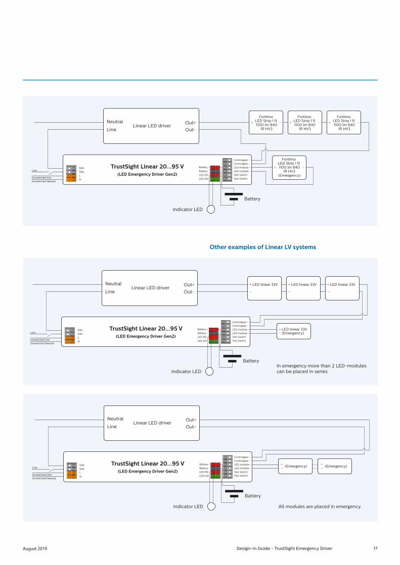
17August 2019 Design-in Guide - TrustSight Emergency Driver
SWLLine
Battery +
Controlgear +Controlgear -LED module +LED module -Test SwitchTest Switch
Battery -
LED RD
LED GN
TrustSight Linear 20...95 V(LED Emergency Driver Gen2)
Neutral Out+ +
Fortimo LED Strip 1 ft 1100 lm 840
1R HV3
Fortimo LED Strip 1 ft 1100 lm 840
1R HV3
Fortimo LED Strip 1 ft 1100 lm 840
1R HV3
-
Out-Linear LED driver
Line
SWLL
NUnswitched lineUnswitched Neutral
Battery
Indicator LED
+ -
Fortimo LED Strip 1 ft 1100 lm 840
1R HV3(Emergency)
+ -
+ -
Other examples of Linear LV systems
SWLLine
Battery +
Controlgear +Controlgear -LED module +LED module -Test SwitchTest Switch
Battery -
LED RD
LED GN
TrustSight Linear 20...95 V(LED Emergency Driver Gen2)
Neutral Out+ + LED linear 33V + LED linear 33V + LED linear 33V
- -
+ LED linear 33V- (Emergency)
-Out-Linear LED driver
Line
SWLL
NUnswitched lineUnswitched Neutral
Battery
Indicator LEDIn emergency more than 2 LED-modules can be placed in series.
SWLLine
Battery +
Controlgear +Controlgear -LED module +LED module -Test SwitchTest Switch
Battery -
LED RD
LED GN
TrustSight Linear 20...95 V(LED Emergency Driver Gen2)
Neutral Out+
+- (Emergency)
Out-Linear LED driver
Line
SWLL
NUnswitched lineUnswitched Neutral
Battery
Indicator LED All modules are placed in emergency.
+- (Emergency)

18 Design-in Guide - TrustSight Emergency Driver August 2019
The amount of light in Emergency mode The amount of light is determined by the numbers and lumens per watt of the LED module(s) connected to the emergency driver.
ExampleApplication (as shown below) is equipped with LED module: Fortimo LED line 1 ft 1100 lm 1R HV3.
The lumen efficacy of the Fortimo LED line 1 ft 1100 lm 1R HV3 is ± 150 lm/W (source: product datasheet)The amount of lumen in emergency mode is:3 W x lumen efficacy of one module
More lumen in emergency mode• Connect a LED module with a higher lumen efficacy• Use a 6 W version instead of a 3 W version (this is not
possible for the point source emergency driver)
Longer light output in emergency mode• Use a 3 hours battery pack
In SeriesIt is important to determine the total forward voltage of the in series connected LED modules The number of LED modules which can be connected to an EM driver is limited by the maximum output voltage of the TrustSight EM driver.
ImportantIt is not advised to mix LED modules with different forward voltage in one system.
i
SWLLine
Battery +
Controlgear +Controlgear -LED module +LED module -Test SwitchTest Switch
Battery -
LED RD
LED GN
TrustSight Linear 20...95 V(LED Emergency Driver Gen2)
Neutral Out+ + line 1 ft 1100 lm1R HV3-
+ line 1 ft 1100 lm
1R HV3(Emergency)
-
+ line 1 ft 1100 lm1R HV3-
+ line 1 ft 1100 lm1R HV3-Out-
Linear LED driverLine
SWLL
NUnswitched lineUnswitched Neutral
Battery
Indicator LED
line 1 ft 1100 lm1R HV3
(Emergency)
+ -

19August 2019 Design-in Guide - TrustSight Emergency Driver
Fortimo LED SLM 2000 lm L13 830Parameter Min Typ Max Unit
Luminous Flux 1810 2020 2230 lm
Module Efficiency 117 lm/W
Correlated Colour Temperature 3000 K
Colour Coordinates (0.434, 0.403) -
Colour Coordinates Premium White (0.430, 0.395) -
Colour Consistency 3 SDCM
CRI >80 -
Radiation Angle 115 deg
Thermal Power 11.9 W
Energy efficiency label A+ -
Optical characteristics - table per CCT
Example 1
TrustSight Basic P 15-55 V 3 W 1 hour, connected to SLM 2000 lm
Wanted : The amount of light in EM modeGiven : Output power in EM mode is 3 W
for 1 hourNeeded : LED efficiency? see datasheet
LED-module 117 lm/W
Answer : 117 * 3 = 351 lm
Example 2
SWLLine
Battery +
Controlgear +Controlgear -LED module +LED module -Test SwitchTest Switch
Battery -
LED RD
LED GN
TrustSight Linear 20...95 V(LED Emergency Driver Gen2)
Neutral Out+ + line 1 ft 1100 lm1R HV3-
+ line 1 ft 1100 lm
1R HV3(Emergency)
-
+ line 1 ft 1100 lm1R HV3-
+ line 1 ft 1100 lm1R HV3-Out-
Linear LED driverLine
SWLL
NUnswitched lineUnswitched Neutral
Battery
Indicator LED
line 1 ft 1100 lm1R HV3
(Emergency)
+ -
Wanted : The amount of light in EM mode per moduleGiven : Output power in EM mode is 3 W for 1 hourNeeded : LED efficiency? see datasheet LED-module LED Line 1 ft 1100 lm 1R HV3 165 lm/W
Answer : Each module consumes 3 W/2 = 1.5 W light output per LED-module is 1.5* 165 lm = 247.5 lm
20 Design-in Guide - TrustSight Emergency Driver August 2019
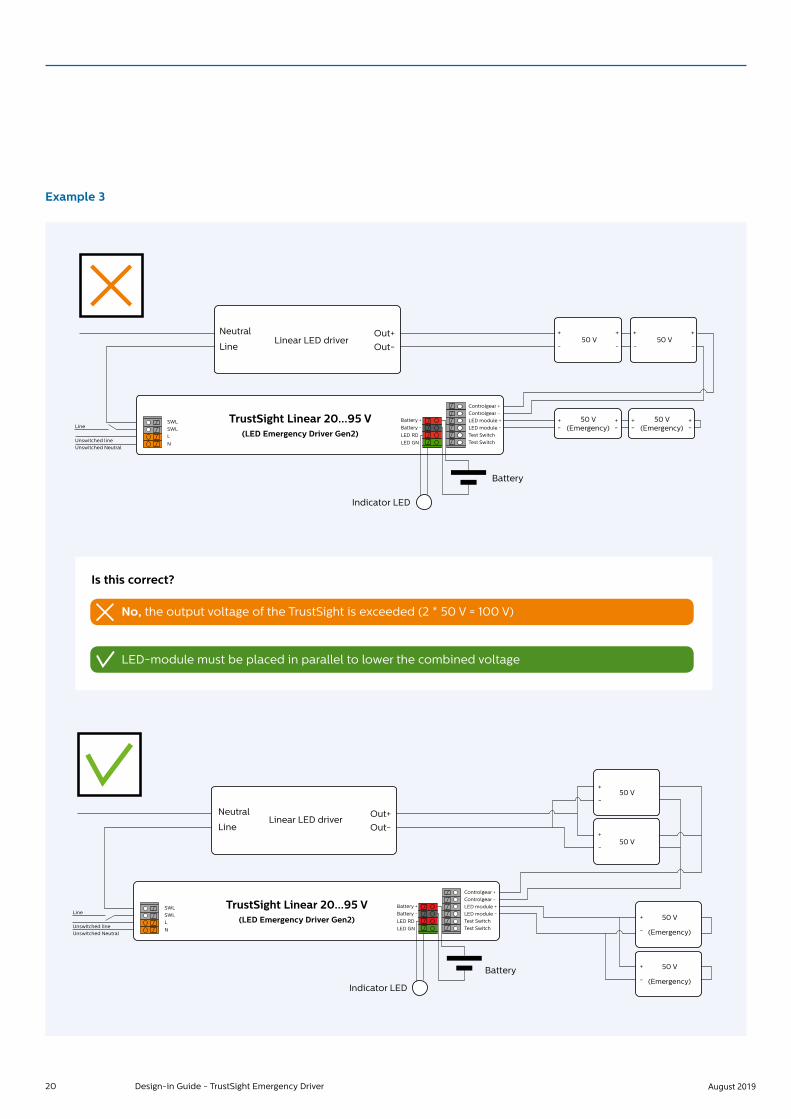
Example 3
SWLLine
Battery +
Controlgear +Controlgear -LED module +LED module -Test SwitchTest Switch
Battery -
LED RD
LED GN
TrustSight Linear 20...95 V(LED Emergency Driver Gen2)
Neutral Out+ +50 V 50 V
+
-
+-
+-
-
+ +
- -
50 V (Emergency)
+-
+-
50 V (Emergency)
Out-Linear LED driver
Line
SWLL
NUnswitched lineUnswitched Neutral
Indicator LED
Battery
SWLLine
Battery +
Controlgear +Controlgear -LED module +LED module -Test SwitchTest Switch
Battery -
LED RD
LED GN
TrustSight Linear 20...95 V(LED Emergency Driver Gen2)
Neutral Out+
+
-
+
-
Out-Linear LED driver
Line
SWLL
NUnswitched lineUnswitched Neutral
50 V
+
-
50 V
(Emergency)
+
-
50 V
(Emergency)
50 V
Battery
Indicator LED
Is this correct?
No, the output voltage of the TrustSight is exceeded (2 * 50 V = 100 V)
LED-module must be placed in parallel to lower the combined voltage

21August 2019 Design-in Guide - TrustSight Emergency Driver
Example 4
SWLLine
Battery +
Controlgear +Controlgear -LED module +LED module -Test SwitchTest Switch
Battery -
LED RD
LED GN
TrustSight Linear 20...95 V(LED Emergency Driver Gen2)
Neutral Out+
+
-
+
-
Out-Linear LED driver
Line
SWLL
NUnswitched lineUnswitched Neutral
50 V
+
-
50 V
(Emergency)
+
-
50 V
(Emergency)
50 V
Battery
Indicator LED
Wanted : The current per LED-module in EM-modeGiven : Output power in EM mode is: 3 W for 1 hourNeeded : LED-module voltage = 50 V
Answer : • Output voltage EM is 50 V (LED-modules are in parallel) • Output current in EM is 3 W / 50 V = 60 mA• Current per LED-module 60 mA / 2 = 30 mA

22 Design-in Guide - TrustSight Emergency Driver August 2019
Example 5
BWLLine
Battery +
Controlgear +Controlgear -LED module +LED module -Test SwitchTest Switch
Battery -
LED RD
LED GN
TrustSight Linear 20...95 V(LED Emergency Driver Gen2)
Neutral Out+50 V 50 V 50 V
-
+
+
+ +
-
50 V-
-Out-Linear LED driver
Line
BWLL
NUnswitched lineUnswitched Neutral
Battery
Indicator LED
(Emergency)
SWLLine
Battery +
Controlgear +Controlgear -LED module +LED module -Test SwitchTest Switch
Battery -
LED RD
LED GN
TrustSight Linear 20...95 V(LED Emergency Driver Gen2)
Neutral Out+
+
-
+
-
Out-Linear LED driver
Line
SWLL
NUnswitched lineUnswitched Neutral
50 V
+
-
50 V
(Emergency)
+
-
50 V
(Emergency)
50 V
Battery
Indicator LED
Are these connections correct?
Yes, the voltage connected to the TrustSight is 50 V.

23August 2019 Design-in Guide - TrustSight Emergency Driver
How to… Wire – general remarks In the datasheet of the EM driver it is stated what:• Wire diameters are accepted• Strip length of the wires are accepted• Up to what wire length the drivers are tested on EMC
Direct wiring between LED driver, LED module, TrustSight EM driver and batteryBe informed that no components are allowed between the LED driver EM-driver and LED modules other than connectors and wiring intended to connect the LED driver to the LED board. For example it is not allowed to install a switch between the driver and LED boards.
2 wires into one connector holeIn some scenarios two wires need to be connected to one connector hole. In this case the pairing has to be done outside the LED driver or EM-driver, resulting in only one wire going into the driver. Two wires into one connector hole are not supported.For the point source applications there is a loop-through addition available when installed as s independent application
FerrulesThe reliability of twin-wire ferrules (or wire end stop), accepting the wires intended to use, should be checked with the supplier of these ferrules.
Cables and wiresFor the point-source applications installed as an independent device there is an additional box available which can be connected to the existing housing to provide loop-through functionality.
Interconnecting LED drivers and LED modulesSee the Design-In Guide for Xitanium Indoor LED drivers and LED modules on www.philips.com/technology.
Electromagnetic compatibility (EMC)Electromagnetic compatibility (EMC) is the ability of a device or system to operate satisfactorily in its electromagnetic environment without causing unacceptable interference in practical situations. TrustSight EM LED drivers meet EMC requirements per CISPR15 ed 7.2. This test is conducted with a reference luminaire, representing a common application that includes a LED driver, TrustSight emergency driver, LED load (incl. heatsink), battery and LED indicator.
Cable length and EMCFor each setup it is advised to perform EMC tests.It also advices to place the battery as close as possible to the housing of the TrustSight emergency-driver.
Examples of what solutions could look like for pairing wires.
Twin-wire ferrules.

24 Design-in Guide - TrustSight Emergency Driver August 2019
How to… Improve EMC performanceBoth applies to a point and linear EM driver. Below a point source LED driver is used as example.
Improvement in EMC PerformanceThe following practical precautions need to be taken into account in a lighting system to minimize EMC:• Minimize the differential mode loop area of the lamp wires going from the driver to the light source by keeping the wires
close together (bundling). This will minimize the magnetic field and reduce the radiated EMI.
• Minimize the common mode parasitic capacitance of the output wiring + light source to earth by keeping the length of the wiresbetween driver and light source as short as possible. Keep the length of the incoming mains wire inside the luminaire as shortas possible.
• Keep mains and control wires(DALI, 0-10 V) separated from the output wires. Do not bundle or cross the wires.
• Do not route any wiring over and/or along the driver enclosure to avoid any coupling/crosstalk with internal components of the driver.
• Ground the lighting system chassis and other internal metal parts to protective earth (class I luminaires): do not let large metal partselectrically insulated from functional or protective earth. Always connect the protective/functional earth/equipotential connector or wire from the driver and use equipotential bonding wires for all large unconnected metal luminaire parts like luminaire housing,driver mounting plate, reflector, heatsink etc. Keep the protective/ functional earth/equipotential wires as short as possible tomaximize their effectiveness and use, as much as possible, large metal areas (chassis, mounting plates, brackets) for earthingpurposes instead. Establish a reliable electrical connection by using a toothed washer and screw(s)fastened with adequate torque.
PE L N
Controls
To LEDs
� To LEDs
�PE L N
Controls
PEPELNControls
To LEDs+-
L NControls
�To LEDs
PELN
Controls
To LEDs
�
PEL NControls
Very large loop area
To LEDs
�
PEL
NControls
To LEDs
✗ PEL NControls
To LEDs
�

25August 2019 Design-in Guide - TrustSight Emergency Driver
Electrical insulation and protective earth
Surge protectionThe TrustSight Emergency drivers have built-in surge protection up to a certain limit according EN 61547. It can withstand 1KV differential mode and 2KV common mode surges. Depending on the mains connected, additional protection against excessive high surge voltages may be required by adding a Surge Protection Device. The actual limit can differ per driver and can be found in the driver’s datasheet.
Touch currentThe TrustSight Emergency LED drivers are designed to meet touch current requirements per IEC 61347-1 standard. The specified maximum values are 0.7 mA peak for IEC and 0.75 mA RMS for UL norms. The test is done with the driver alone. In a luminaire, touch current may be higher, since the LED load may introduce additional touch current. Precautions may be required on the luminaire level and if multiple drivers are used in a single luminaire.
InsulationThe test switch, LED indicator and the battery are basic insulated from the mains power supply.The output of the TrustSight drivers is double insulated to the mains input whereas the output of the point version is also SELV.
WarningConnecting the luminaire to Protective Earth. If the driver needs to be connected to Protective Earth, like non-isolated Xitanium LED drivers. then also the luminaire needs to be connected to protective earth in order to comply with safety regulations and EMI. Please also consult the Design-In-Guide of the Xitanium Indoor Linear LED drivers on www.philips.com/technology
i
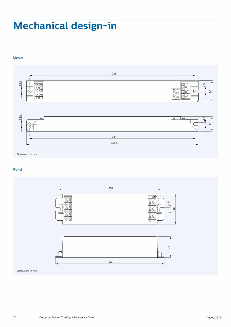
26 Design-in Guide - TrustSight Emergency Driver August 2019
Linear
235
235
ø4
.5ø
4.5
4.5
4.5
2130
244.5
Mechanical design-in
Point
154
164
4.5
46
32
Dimensions in mm.
Dimensions in mm.

27August 2019 Design-in Guide - TrustSight Emergency Driver
Loop through
TrustSight point mains side connectionsFull DALI and Full loop-through for cables with 1.5 mm2 conductors (Loop trhough with 2.5 mm2 cables looks like itwill be very unpractical).
208±0.8
45.
6±0
.5
74±0
.5
32±0
.5
Point with stain relief
Dimensions in mm.
SWL in
DALI inDALI inDALI outDALI out
SWL outSWN in
SWN out
LN
TrustSight
TrustSight Loop Through adopter
DALI in 1.5 mm2
DALI out 1.5 mm2
Switched L/N out 1.5 mm2 max to AC driver
DALI out 1.5 mm2 max to AC driver
Unswitched L/N 1.5 mm2
Unswitched L/N 1.5 mm2 out LT
Mounting diameter LED = 6 mmCable length = 1 meter
Mounting diameter switch = 7 mmCable length = 1 meter
SwitchIndicator LED

28 Design-in Guide - TrustSight Emergency Driver August 2019
Thermal design-in
This chapter describes two aspects of the thermal design of the Philips TrustSight Emergency system
1. The TrustSight driverf and relationship between Tc point and lifetime of the driver
2. The TrustSight battery
To facilitate design-in of LED drivers, the critical thermal management points of the LED driver are set out in this section. In Philips’ product design phase all possible precautions have been taken to keep the component temperature as low as possible. However, the design of the luminaire and the ability to guide the heat out of the luminaire are of utmost importance. If these thermal points are taken into account this will ensure the optimum performance and lifetime of the system.
Case Temperature Point (Tc point)To achieve optimal lifetime and reliability, it is critical that the temperature of the components in the driver remains within its rating. In the LED driver design, all precautions are taken to ensure that the components within the driver are at the lowest possible temperatures.
The case temperature (Tc) is a reference for the temperatures of the critical internal driver components. The location of the Tc point is identified on the product label. Tc point is marked by the *-sign on the label of the driver.
To measure Tc at the Tc pointThe temperature can be measured using a thermocouple that is firmly glued to the driver housing. For a representative measurement the temperature mustbe stable before any reliable data can be obtained(typically > 0.5 hours).
Relation between Tc and ambient temperatureThe Tc increases, by approximation, linearly with the ambient temperature (Tamb). The temperature offset between Tamb and Tc depends on the thermal design of the luminaire. The TrustSight LED driver has been designed for indoor use. For approved ambient temperature range please check the associated LED driver datasheet on www.philps.com/technology.
ElcoCoil
Rth (comp � case)
Tc point
Fet
Schematic represenatation of intenal thermal resistances and driver T-case

29August 2019 Design-in Guide - TrustSight Emergency Driver
Battery storage temperatureAs mentioned before (refer to the section batteries) the batteries are pre-charged before shipment to extend their shelf life. The indicated date on the batteries is valid when the batteries are stored at temperatures between -20 °C and 30 °C. When the batteries are stored at temperatures between -20 °C and 40 °C they must be used within 2 months, and when stored at 50 °C, they should be used within one week.
Battery operating temperatureThe battery operating temperature is specified as follows:
The battery has no dedicated Tc point for thermal verification. It is advised to glue a thermocouple to the center part of the battery body to measure its temperature.
Operating the batteries outside these temperature windows as shown above will reduce the lifetime of the batteries and must be avoided.
State Min Max
Charging 0 °C 55 °C
Discharging 20 °C 50 °C

30 Design-in Guide - TrustSight Emergency Driver August 2019
DALIDigital Addressable Lighting Interface, or DALI, is a digital communication protocol popular in the lighting industry. It is an IEC standard and there are many control devices from Philips and other manufacturers that communicate using DALI. The voltage across DALI wires is typically 16 V (refer IEC specification for details) and it is polarity insensitive. For more information on DALI, refer to the IEC specification for DALI protocol.• IEC 62386: 102 - General requirements - Control gear.• IEC 62386: 207 - Particular requirements for control gear
- LED modules.• IEC 62386: 202 - Particular requirements for control gear
- Self-contained emergency lighting.
The DALI standard allows additional emergency features to be configured as options.
Every emergency gear conforming to the DALI emergency gear standard IEC 62386-202 is able to carry out an emergency test when commanded across the DALI bus – either a short (function) test or a discharge (duration) test.
The emergency gear carries out the test autonomously when requested to do so; it selects its battery as the power source during the test, so that there is no need to interrupt its permanent mains supply. Once the test is complete the test results can then be read over the DALI bus. In the event that the permanent mains supply fails during a test, the DALI emergency gear immediately stops the test and goes into full emergency operation, so that the requirement for the escape lighting to illuminate quickly, reliably and unconditionally is met.
Each DALI emergency gear is individually addressable on its DALI bus and each gear can be commanded individually to carry out an emergency test. So rather than testing all the emergency luminaires in one zone together each emergency luminaire in the zone can be tested at a different time, therefore ensuring the safety of the zone at all times.
If the emergency and normal drivers in a luminaire are both DALI gear, then each can be separately addressed on the same DALI bus. This allows common wiring to be used for both normal lighting control and emergency test control. During a failure of the permanent mains supply, the TrustSight acts autonomously to provide escape lighting, regardless of the state of the DALI bus.
Controllability

31August 2019 Design-in Guide - TrustSight Emergency Driver
Unswitched lineSwitched Neutral
Switched Line
DALI
SW L
DA in
DA out
DA in
DA out10
9
8
7
6
5
4
3
2
1
SW N
SW L
SW N
N
LUnswitched Neutral
Unswitched line
Line
DALI
DA
DA
SW L
SW L
N
LUnswitched Neutral
Default test times are factory pre-set, in accordance with the DALI standard EN 62386-202, to conduct an automatic function test every 7 days and a duration test every 52 weeks. Since the DELAY time is factory pre-set to Zero, all units are tested at the same time. Test times can be changed via DALI.
TrustSight point TrustSight linear

32 Design-in Guide - TrustSight Emergency Driver August 2019
Quality and Reliability
Item Technical Data International standards Clauses
Cells intended for permanent
charge at elevated temperature
Yes IEC 61-951-2 (ex IEC61436 §7.2
IEC 61-951-2 (ex IEC61436 §7.2
§7.4.2.3 and 7.9
Expected operation life under folowing conditions
Maximum continuous temperature
Maximum occasional temperature
Discharge
> 4 years
+ 50 °C (55C @ charging)
+ 65 °C (1 month)
1 discharge / year
Relevant Standards
Compliance and approval Generated disturbances, EMI and EMC
EN 55015 A2/CISPR15 Conducted EMI 9 kHz-30 MHz
EN 55015 A2/CISPR15 Radiated EMI 30 MHz-300 MHz
IEC 61000-3-2 A1 + A2 Limits for harmonic current emissions
IEC 61000-3-3 EMC – Limitation of voltage fluctuation and flicker in low voltage supply systems for equipment rated up to 16 A
Immunity
IEC / EN 61547, A12000 Equipment for general lighting purposes – EMC immunity requirements
IEC / EN 61000-4-2 Electrostatic Discharge
IEC / EN 61000-4-3 A1 Radiated radio frequency, electromagnetic field immunity
IEC / EN 61000-4-4 Electrical fast transient/burst immunity
IEC / EN 61000-4-5 Surge immunity
IEC / EN 61000-4-6 Conducted disturbances induced by RF fields
IEC / EN 61000-4-11 Voltage dips, short interrupts, voltage variations
Performance
IEC 62384 DC or AC supplied electronic control gear for LED modules - Performance requirements
IEC 62386 Digital Addressable Lighting Interface (DALI)
Safety standards
IEC 61347-1 General and safety requirements
IEC 61347-2-13 LED Particular requirements for DC or AC supplied electronic control gears for LED modules
Emergency standards
IEC 61347-2-3 Particular additional safety requirement for AC/DC supplied electronic ballasts for emergency lighting
IEC 61347-2-7 Particular requirements for DC supplied electronic ballasts for emergency lighting
LifetimeThe batteries have a life time expectancy of 4 years when maintained properly, as shown in the table below

33August 2019 Design-in Guide - TrustSight Emergency Driver
Battery installation at OEMAfter the TrustSight Emergency has been installed in a luminaire, the luminaire should not be left in emergency mode (battery powered light) to prevent the batteries from draining. After mains disconnect, the battery should be disconnected and (after a few seconds) connected again. In this way, no energy will be drained from the battery (except for its self-discharge) during the time before installation.
Mains voltage fluctuationsThe driver is able to withstand high and low mains voltages for limited periods of time.
Low mains voltageA continuous low AC voltage (<198 V) has no adverse effect on the driver’s lifetime. However, according IEC 61347-2-7 Ed.3 Clause 21, below 195 V AC mains the TrustSight is allowed to go into emergency mode.
High mains voltageA high mains voltage will stress the driver and have an adverse effect on the lifetime (maximum 320 V for a period of 48 hours, and 400 V for a period of one hour).
Marking
Standard Description
CE marking
ENEC marking the European certification mark for
electrical products that gives a product acces to the
markets of countries in the European Union, EFTA, and a
number of Eastern European counties. 05 is the body
certified to give the marking, KEMA/DEKRA
110
F-marking, temperature declared, thermally protected
ballest/transformer(s) symbol acc. IEC61347-1 Clause 7.1.
m, 110 °C
EL
Electronic gear complying with IEC61347-2-7 shall be
marked with this symbol.

34 Design-in Guide - TrustSight Emergency Driver August 2019
Disclaimer
Note that the information provided in this document is subject to change.
This document is not an official testing certificate and cannot be used or construed as a document authorizing or otherwise supporting an official release of a luminaire. The user of this document remains at all times liable and responsible for any and all required testing and approbation prior to the manufacture and sale of any luminaire. The recommendations and other advice contained in this document, are provided solely for informational purposes for internal evaluation by the user of this document. Signify does not make and hereby expressly disclaims any warranties or assurances whatsoever as to the accuracy, completeness, reliability, content and/or quality of any recommendations and other advice contained in this document, whether express or implied including, without limitation, any warranties of satisfactory quality, fitness for a particular purpose or non-infringement. Signify has not investigated, and is under no obligation or duty to investigate, whether the recommendations and other advice contained in this document are, or may be, in conflict with existing patents or any other intellectual property rights. The recommendations and other advice contained herein are provided by Signify on an “as is” basis, at the user’s sole risk and expense. Specifically mentioned products, materials and/or tools from third parties are only indicative and reference to these products, materials and/or tools does not necessarily mean they are endorsed by Signify. Signify gives no warranties regarding these and assumes no legal liability or responsibility for any loss or damage resulting from the use of the information thereto given here. Philips and the Philips Shield Emblem are registered trademarks of Koninklijke Philips N.V. All other trademarks are owned by Signify Holding or their respective owners.

©2019 Signify Holding B.V. All rights reserved.Note that the information provided in this document is subject to change.
Date of release: August 14, 2019 v2www.philips.com/oem