Truss Performance and Packaging Metrics - NASA Performance and Packaging Metrics Martin M. Mikulas1,...
10
Truss Performance and Packaging Metrics Martin M. Mikulas 1 , Timothy J. Collins 2 , William Doggett 2 , John Dorsey 2 , and Judith Watson 2 1 National Institute of Aerospace, Hampton, VA, 2 NASA, Langley Research Center, Hampton,VA 757-356-1529; [email protected] Abstract. In the present paper a set of performance metrics are derived from first principals to assess the efficiency of competing space truss structural concepts in terms of mass, stiffness, and strength, for designs that are constrained by packaging. The use of these performance metrics provides unique insight into the primary drivers for lowering structural mass and packaging volume as well as enabling quantitative concept performance evaluation and comparison. To demonstrate the use of these performance metrics, data for existing structural concepts are plotted and discussed. Structural performance data is presented for various mechanical deployable concepts, for erectable structures, and for rigidizable structures. Keywords: Truss, structures, deployable, inflatable, erectable, packaging, efficiency, metrics, modular, in-space fabrication. PACS: 89.75.-k INTRODUCTION There is a continual desire in the space community to build increasingly larger structures for space exploration and for the collection or reflection of electromagnetic waves of varying wavelength. In order to achieve these goals it is desirable to have lower mass structures with better launch vehicle packaging efficiency. As new structures are developed for these increasingly aggressive missions, it is essential to have performance metrics that enable a rational quantitative comparison between proposed structural architectures. A previous study was conducted on the structural efficiency of long slender space columns for which reducing mass was the primary design consideration (Mikulas, 1978). The general types of columns considered in that study are shown in figure 1. Although that study presented useful design information for the specific case of trusses loaded in compression, no consideration was given to the resulting truss diameter or to the implications of packaging constraints. In the present paper a set of performance metrics are derived from first principals for a general beam to assess the efficiency of competing structural architectures in terms of stiffness, strength, and mass. For the first time these performance metrics are cast in terms of the beam diameter enabling a structural efficiency to be investigated as a function of packaging parameters. The use of these performance metrics provides unique insight into the primary drivers for lowering structural mass and packaging volume as well as enabling quantitative concept performance information. In many applications there are constraints on either the in-service truss diameter or packaging volume that must be considered. In this paper a new set of performance metrics are derived for which packaging constraints are a primary consideration. This set of performance metrics provides direct information as to the impact of truss diameter on structural mass, stiffness, and strength. The essential approach herein is to provide a set of example performance metric curves that will serve as a reference for competing beam concepts. A few experimental data points are provided to demonstrate the use of the reference performance metrics, however, the value of these curves will increase greatly as more data points are obtained. https://ntrs.nasa.gov/search.jsp?R=20060008916 2018-05-31T07:46:11+00:00Z
-
Upload
vuongduong -
Category
Documents
-
view
223 -
download
2
Transcript of Truss Performance and Packaging Metrics - NASA Performance and Packaging Metrics Martin M. Mikulas1,...
Truss Performance and Packaging Metrics
Martin M. Mikulas1, Timothy J. Collins2, William Doggett2, John Dorsey2, and
Judith Watson2
1National Institute of Aerospace, Hampton, VA, 2NASA, Langley Research Center, Hampton,VA
757-356-1529; [email protected]
Abstract. In the present paper a set of performance metrics are derived from first principals to assess the efficiency of competing space truss structural concepts in terms of mass, stiffness, and strength, for designs that are constrained by packaging. The use of these performance metrics provides unique insight into the primary drivers for lowering structural mass and packaging volume as well as enabling quantitative concept performance evaluation and comparison. To demonstrate the use of these performance metrics, data for existing structural concepts are plotted and discussed. Structural performance data is presented for various mechanical deployable concepts, for erectable structures, and for rigidizable structures.
Keywords: Truss, structures, deployable, inflatable, erectable, packaging, efficiency, metrics, modular, in-space fabrication. PACS: 89.75.-k
INTRODUCTION
There is a continual desire in the space community to build increasingly larger structures for space exploration and for the collection or reflection of electromagnetic waves of varying wavelength. In order to achieve these goals it is desirable to have lower mass structures with better launch vehicle packaging efficiency. As new structures are developed for these increasingly aggressive missions, it is essential to have performance metrics that enable a rational quantitative comparison between proposed structural architectures. A previous study was conducted on the structural efficiency of long slender space columns for which reducing mass was the primary design consideration (Mikulas, 1978). The general types of columns considered in that study are shown in figure 1. Although that study presented useful design information for the specific case of trusses loaded in compression, no consideration was given to the resulting truss diameter or to the implications of packaging constraints. In the present paper a set of performance metrics are derived from first principals for a general beam to assess the efficiency of competing structural architectures in terms of stiffness, strength, and mass. For the first time these performance metrics are cast in terms of the beam diameter enabling a structural efficiency to be investigated as a function of packaging parameters. The use of these performance metrics provides unique insight into the primary drivers for lowering structural mass and packaging volume as well as enabling quantitative concept performance information. In many applications there are constraints on either the in-service truss diameter or packaging volume that must be considered. In this paper a new set of performance metrics are derived for which packaging constraints are a primary consideration. This set of performance metrics provides direct information as to the impact of truss diameter on structural mass, stiffness, and strength. The essential approach herein is to provide a set of example performance metric curves that will serve as a reference for competing beam concepts. A few experimental data points are provided to demonstrate the use of the reference performance metrics, however, the value of these curves will increase greatly as more data points are obtained.
https://ntrs.nasa.gov/search.jsp?R=20060008916 2018-05-31T07:46:11+00:00Z
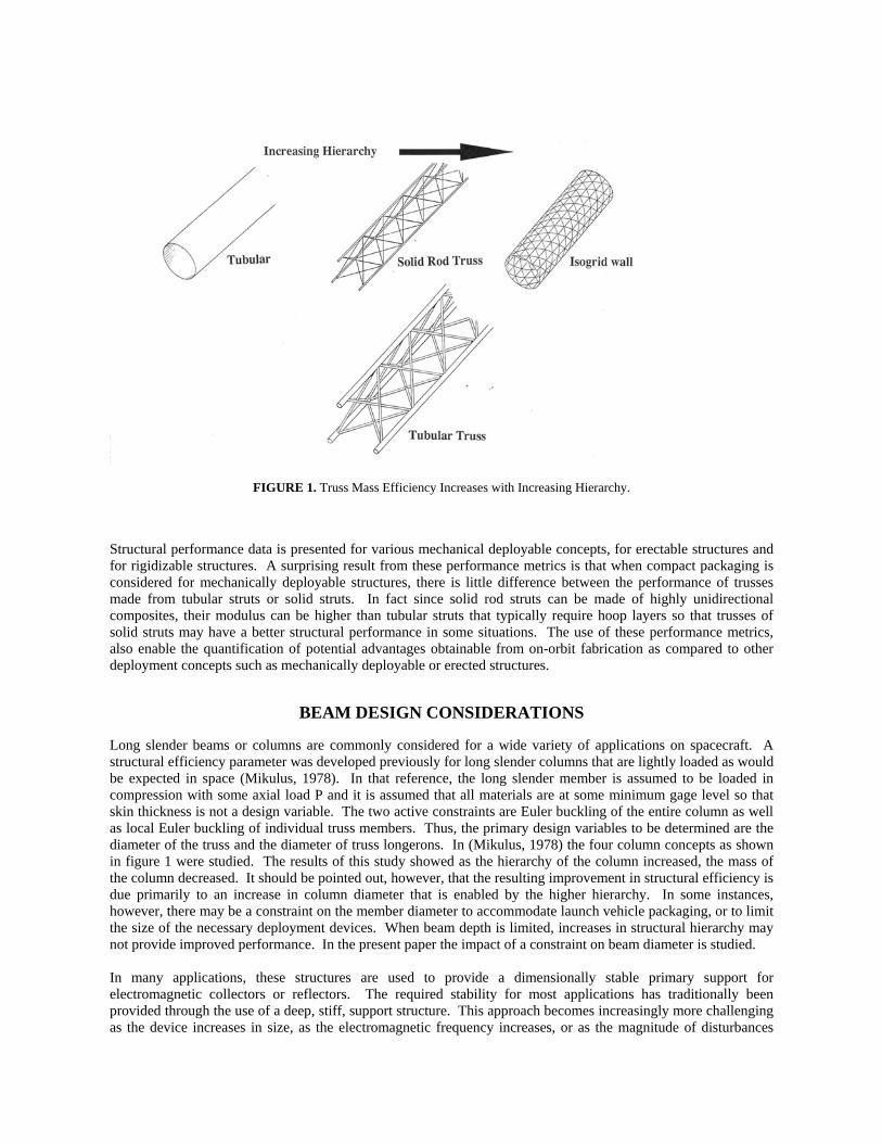
FIGURE 1. Truss Mass Efficiency Increases with Increasing Hierarchy.
Structural performance data is presented for various mechanical deployable concepts, for erectable structures and for rigidizable structures. A surprising result from these performance metrics is that when compact packaging is considered for mechanically deployable structures, there is little difference between the performance of trusses made from tubular struts or solid struts. In fact since solid rod struts can be made of highly unidirectional composites, their modulus can be higher than tubular struts that typically require hoop layers so that trusses of solid struts may have a better structural performance in some situations. The use of these performance metrics, also enable the quantification of potential advantages obtainable from on-orbit fabrication as compared to other deployment concepts such as mechanically deployable or erected structures.
BEAM DESIGN CONSIDERATIONS
Long slender beams or columns are commonly considered for a wide variety of applications on spacecraft. A structural efficiency parameter was developed previously for long slender columns that are lightly loaded as would be expected in space (Mikulus, 1978). In that reference, the long slender member is assumed to be loaded in compression with some axial load P and it is assumed that all materials are at some minimum gage level so that skin thickness is not a design variable. The two active constraints are Euler buckling of the entire column as well as local Euler buckling of individual truss members. Thus, the primary design variables to be determined are the diameter of the truss and the diameter of truss longerons. In (Mikulus, 1978) the four column concepts as shown in figure 1 were studied. The results of this study showed as the hierarchy of the column increased, the mass of the column decreased. It should be pointed out, however, that the resulting improvement in structural efficiency is due primarily to an increase in column diameter that is enabled by the higher hierarchy. In some instances, however, there may be a constraint on the member diameter to accommodate launch vehicle packaging, or to limit the size of the necessary deployment devices. When beam depth is limited, increases in structural hierarchy may not provide improved performance. In the present paper the impact of a constraint on beam diameter is studied. In many applications, these structures are used to provide a dimensionally stable primary support for electromagnetic collectors or reflectors. The required stability for most applications has traditionally been provided through the use of a deep, stiff, support structure. This approach becomes increasingly more challenging as the device increases in size, as the electromagnetic frequency increases, or as the magnitude of disturbances
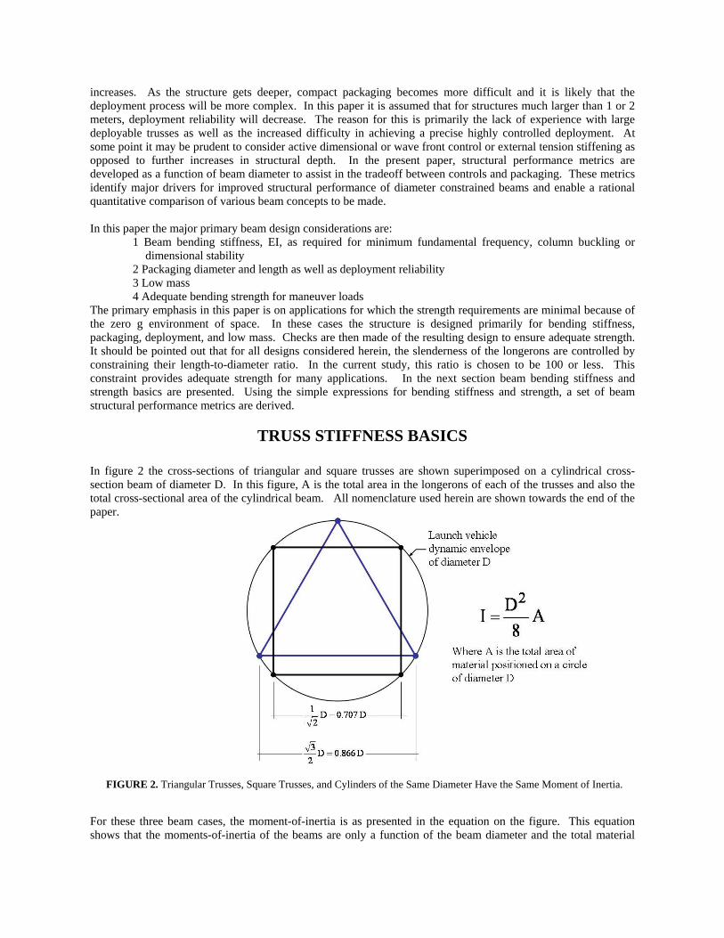
increases. As the structure gets deeper, compact packaging becomes more difficult and it is likely that the deployment process will be more complex. In this paper it is assumed that for structures much larger than 1 or 2 meters, deployment reliability will decrease. The reason for this is primarily the lack of experience with large deployable trusses as well as the increased difficulty in achieving a precise highly controlled deployment. At some point it may be prudent to consider active dimensional or wave front control or external tension stiffening as opposed to further increases in structural depth. In the present paper, structural performance metrics are developed as a function of beam diameter to assist in the tradeoff between controls and packaging. These metrics identify major drivers for improved structural performance of diameter constrained beams and enable a rational quantitative comparison of various beam concepts to be made. In this paper the major primary beam design considerations are:
1 Beam bending stiffness, EI, as required for minimum fundamental frequency, column buckling or dimensional stability
2 Packaging diameter and length as well as deployment reliability 3 Low mass 4 Adequate bending strength for maneuver loads The primary emphasis in this paper is on applications for which the strength requirements are minimal because of the zero g environment of space. In these cases the structure is designed primarily for bending stiffness, packaging, deployment, and low mass. Checks are then made of the resulting design to ensure adequate strength. It should be pointed out that for all designs considered herein, the slenderness of the longerons are controlled by constraining their length-to-diameter ratio. In the current study, this ratio is chosen to be 100 or less. This constraint provides adequate strength for many applications. In the next section beam bending stiffness and strength basics are presented. Using the simple expressions for bending stiffness and strength, a set of beam structural performance metrics are derived.
TRUSS STIFFNESS BASICS In figure 2 the cross-sections of triangular and square trusses are shown superimposed on a cylindrical cross-section beam of diameter D. In this figure, A is the total area in the longerons of each of the trusses and also the total cross-sectional area of the cylindrical beam. All nomenclature used herein are shown towards the end of the paper.
FIGURE 2. Triangular Trusses, Square Trusses, and Cylinders of the Same Diameter Have the Same Moment of Inertia.
For these three beam cases, the moment-of-inertia is as presented in the equation on the figure. This equation shows that the moments-of-inertia of the beams are only a function of the beam diameter and the total material
area at a diameter D. It should also be pointed out that for simple trusses, the moment-of-inertia is isotropic with respect to angle about the beam axis. Thus, it is straight forward to compare the bending stiffness of the three beams.
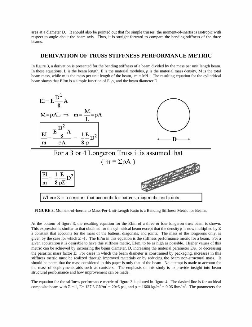
DERIVATION OF TRUSS STIFFNESS PERFORMANCE METRIC In figure 3, a derivation is presented for the bending stiffness of a beam divided by the mass per unit length beam. In these equations, L is the beam length, E is the material modulus, ρ is the material mass density, M is the total beam mass, while m is the mass per unit length of the beam, m = M/L. The resulting equation for the cylindrical beam shows that EI/m is a simple function of E, ρ, and the beam diameter D.
FIGURE 3. Moment-of-Inertia to Mass-Per-Unit-Length Ratio is a Bending Stiffness Metric for Beams.
At the bottom of figure 3, the resulting equation for the EI/m of a three or four longeron truss beam is shown. This expression is similar to that obtained for the cylindrical beam except that the density ρ is now multiplied by Σ a constant that accounts for the mass of the battens, diagonals, and joints. The mass of the longerons only, is given by the case for which Σ =1. The EI/m in this equation is the stiffness performance metric for a beam. For a given application it is desirable to have this stiffness metric, EI/m, to be as high as possible. Higher values of this metric can be achieved by increasing the beam diameter, D, increasing the material parameter E/ρ, or decreasing the parasitic mass factor Σ. For cases in which the beam diameter is constrained by packaging, increases in this stiffness metric must be realized through improved materials or by reducing the beam non-structural mass. It should be noted that the mass considered in this paper is only that of the beam. No attempt is made to account for the mass of deployments aids such as canisters. The emphasis of this study is to provide insight into beam structural performance and how improvement can be made. The equation for the stiffness performance metric of figure 3 is plotted in figure 4. The dashed line is for an ideal composite beam with Σ = 1, E= 137.8 GN/m2 = 20e6 psi, and ρ = 1660 kg/m3 = 0.06 lbm/in3. The parameters for

the dashed line were chosen to provide a reasonably aggressive, yet achievable, reference against which other beams could be compared.
FIGURE 4. Bending-Stiffness-Metric Reference Curves for Beams. The solid line is for the same set of composite parameters except that Σ is taken to be 4 to account for the battens, diagonals and joints. This value of 4 was chosen after reviewing the historical mass characteristics of numerous space trusses. This chart can now be used to compare various space trusses to provide an understanding of their relative performance.
FIGURE 5. Available Space Beam Data Plotted on Stiffness Performance Metric Chart.
EXPERIMENTAL AND PROJECTED PERFORMANCE METRICS
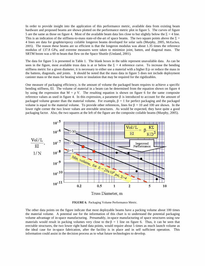
In order to provide insight into the application of this performance metric, available data from existing beam hardware and proposed beams are shown plotted on the performance metric plot in figure 5. The curves of figure 5 are the same as those on figure 4. Most of the available beam data lies close to but slightly below the Σ = 4 line. This is an indication of the stiffness-to-mass state-of-the-art of space beams. The two square points above the Σ = 4 lines are data for graphite/epoxy coilable longeron beams developed for solar sails (Murphy, 2005, McEachen, 2005). The reason these beams are so efficient is that the longeron modulus was about 1.35 times the reference modulus of 137.8 GPa, and extreme measures were taken to minimize joint, batten, and diagonal mass. The SRTM boom was a 60 m beam that flew on the Space Shuttle (Umland, 2001). The data for figure 5 is presented in Table 1. The blank boxes in the table represent unavailable data. As can be seen in the figure, most available truss data is at or below the Σ = 4 reference curve. To increase the bending stiffness metric for a given diameter, it is necessary to either use a material with a higher E/ρ or reduce the mass in the battens, diagonals, and joints. It should be noted that the mass data in figure 5 does not include deployment canister mass or the mass for heating wires or insulation that may be required for the rigidizables. One measure of packaging efficiency, is the amount of volume the packaged beam requires to achieve a specific bending stiffness, EI. The volume of material in a beam can be determined from the equation shown on figure 4 by using the expression that M = ρ V. The resulting equation is shown on figure 6 for the same composite reference values as used in figure 4. In this expression, a parameter β is introduced to account for the amount of packaged volume greater than the material volume. For example, β = 1 for perfect packaging and the packaged volume is equal to the material volume. To provide other references, lines for β = 10 and 100 are shown. In the lower right corner the two lower values are erectable structures. As would be expected, they have quite a good packaging factor. Also, the two squares at the left of the figure are the composite coilable beams (Murphy, 2005).
FIGURE 6. Packaging Volume Performance Metric. The other data points on the figure indicate that most deployable beams have a packing volume about 100 times the material volume. A potential use for the information of this chart is to understand the potential packaging volume advantage of in-space manufacturing. Presumably, in-space manufacturing of space structures using raw materials would result in packing volumes very close to the β = 1 line on figure 6. Thus, it can be seen that erectable structures, the two lower right hand data points, would require about 5 times as much launch volume as the ideal case for in-space fabrication, after the facility is in place and in self sufficient operation. This information could assist in the decision process as to what future technologies to develop.

FIGURE 7. Packaging Length Performance Metric. For some applications, an important design factor is the length in which a beam packages in the launch vehicle. In figure 7 a packaging length reference curve is plotted to enable a comparison of various space beams. The equation shown in the figure is derived by assuming that each bay of the truss will package in a length equivalent to 2 longeron diameters. The curve shown is primarily applicable to mechanically deployable beams. In this figure, the important issue is the value of the ordinate, the ratio of the beams packaged length, LP, to its deployed length, LD. Other beam concepts can be presented on this chart as a means of comparison. For example, the coilable longeron beams are shown to package in less than one half of the mechanical deployable reference curve.
FIGURE 8. Bending Moment Strength Performance Metric.
In figure 8 an expression is presented for the bending moment strength of a four longeron truss beam divided by the mass per unit length of the beam. This is the metric that indicates the strength performance of a beam. As before, this equation is plotted for the same parameters as figure 4 providing a bending strength reference against which various beam concepts can be compared. For this plot the slenderness of the struts (length over diameter) is constrained to be 100. This slenderness constraint is imposed to ensure that the strut acts as a proper column in the presence of imperfections and thermal distortions. However, since it is imposed, it ensures a finite value of bending strength that may be adequate for most applications. It should be noted that many beams have a lower slenderness ratio than 100 so it is expected that they would have a higher strength thant shown on this strength metric plot. Of course this slenderness value must be evaluated for each particular application.
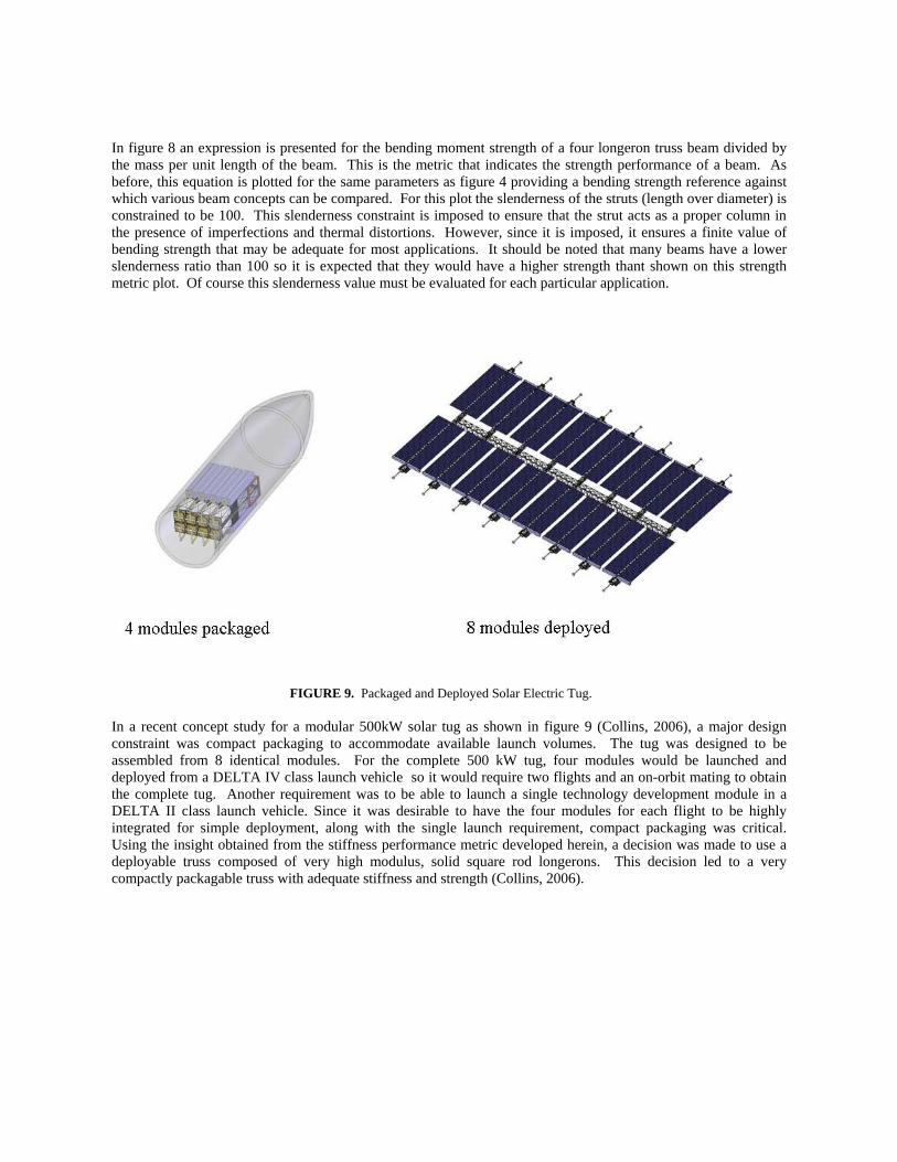
FIGURE 9. Packaged and Deployed Solar Electric Tug. In a recent concept study for a modular 500kW solar tug as shown in figure 9 (Collins, 2006), a major design constraint was compact packaging to accommodate available launch volumes. The tug was designed to be assembled from 8 identical modules. For the complete 500 kW tug, four modules would be launched and deployed from a DELTA IV class launch vehicle so it would require two flights and an on-orbit mating to obtain the complete tug. Another requirement was to be able to launch a single technology development module in a DELTA II class launch vehicle. Since it was desirable to have the four modules for each flight to be highly integrated for simple deployment, along with the single launch requirement, compact packaging was critical. Using the insight obtained from the stiffness performance metric developed herein, a decision was made to use a deployable truss composed of very high modulus, solid square rod longerons. This decision led to a very compactly packagable truss with adequate stiffness and strength (Collins, 2006).

TABLE 1. Available space beam data used in figure 5.
CONCLUSIONS A set of performance metrics are derived from first principals to assess the efficiency of competing space truss structural concepts in terms of mass, stiffness, strength, for designs that are constrained by packaging size. The use of these performance metrics provides unique insight into the primary drivers for lowering structural mass and packaging volume as well as enabling quantitative concept performance information and comparison. The performance metrics were developed for beam bending stiffness, beam bending strength, beam packaging length, and beam packaging volume. A few available beam data points are shown on the performance metric curves to demonstrate their use and to establish current beam performance trends. Specific observations from this study are as follows: 1) Most currently available deployable structures have a mass that is a factor of four or greater than the structural mass required to obtain the required bending stiffness, and use composite materials of only moderately high stiffness. 2) A significant improvement in beam efficiency can be obtained by reducing the non-structural mass factor as well as making use of higher modulus composites. 3) In the 0-g environment of space, beam bending strength requirements can be reduced using active controls or tension stiffening and this may allow the use of trusses of solid rods that package more compactly than trusses of tubular struts. 4) For stiffness designs, the mass of trusses of solid rods and tubular struts made of the same material are equal. 5) Solid rod struts allow the use of unidirectional, high modulus, composites, so in many instances they may result in lower mass designs. 6) Insight obtained from these new performance metrics can lead to a new generation of structures with highly improved packaging and deployment characteristics and the modular use of heritage hardware. 7) Making use of these observations led to the design of a deployable solar electric space tug that packaged very compactly.
Fiber Glass Coilable ABLE
Gr/Ep Coilable ABLE
Isogrid ILC
SRTM ABLE
SSP Rigidizable L’Garde
ISAT Reference rigidizable Langley
2m erectable Langley
Space Station, 5m erectable Langley
E, GPa 51.7 188 153.7 165.5 65.8 41.34 137.8 (20E6 psi)
186
ρ, kg/m3 2020 1660 1660 1660 1660 1660 1660 1800 Diameter,m 0.394 0.394 0.191 1.12 1.36 3.46 2.83 7.07
EI, Nm2 0.01E7 0.008E7 0.0002E7 1.58E7 0.154E7 13.5E7 6.64E7 69.6E7
m, kg/m 0.39 0.07 .07 5.23 0.7 7.3 6 9.99 Lp/Ld 0.017 0.0088 NA 0.023 --- --- NA NA Mom. Nm 270 48.6 63.6 6500 867 5280 13,000 88,000 Number of longerons 3 3 16 4 3 3 4 4
Longeron diameter, m
See below
See below
See below 0.0157 0.035 0.152 0.0254 0.0508
Longeron thickness, mm
5.92x6.2 rect.
2.79x2.9 rect.
.8x.99 rect.
Solid round 0.305 1.52 1.52 2.3
Longeron Length, m 0.23 0.23 0.065 0.6975 1.709 3 2 5
Reference Murphy 2005
Murphy 2005
Lin 2005
Umland 2001
Guidanean 2002
Mikulas Study
Collins 1989
Lake 1990

NOMENCLATURE
A = total area in beam that contributes to bending stiffness (m2)125
E = modulus of elasticity (N/m2) I = moment of inertia of beam (m4) m = mass per unit length (kg/m) M = total beam mass (kg) Mom = moment strength of beam (Nm) ρ = material mass density (kg/m3) Σ = factor to account for parasitic mass of diagonals,
battens, and joints
L = length (m) d = longeron diameter (m) D = truss diameter (m) r = strut radius of gyration (m) l = strut length (m) LP = beam length packaged LD = beam length deployed Vol = packaged volume of beam (m3)
ACKNOWLEDGMENTS
The authors would like to thank NASA and DARPA for providing the funds that enabled this research.
REFERENCES
Agnes, Gregory S., et al., “Preliminary Analysis of the 30-m Ultraboom Flight Test Article,” AIAA 2005-1972, 46th AIAA SDM,April 18-21, 2005, Austin, TX
Collins, Timothy, et al., “Support Trusses for Large Precision Segmented Reflectors: Preliminary Design and Analysis,” NASATM 101560, March, 1989.
Collins, Timothy, et al., “Modular Solar Electric Tug Spacecraft Definition, Including Dynamic Analysis, Sizing, Packaging, Deployment and Assembly,” in these proceedings of Space Technology and Applications International Forum (STAIF-2006), edited by M. El-Genk, American Institute of Physics, Melville, New York, 2006.
Guidanean, Koorosh, et al., “An Inflatable truss Structure Based on New Sub-Tg Polyurethane Composites,” AIAA 2002-1593, 43rd AIAA SDM, 2002
Lake, Mark S., “Analysis and Testing of Axial Compression in Imperfect Slender Truss Struts,” NASA TM 4174, February, 1990.
Lin, John K., “Ultra Lightweight Isogrid Boom Space Experiment,” AIAA 2005-1971, 46th AIAA SDM, April 18-21, 2005, Austin, TX
McEachen, Michael E., et al., “The ST8 SAILMAST Validation Experiment,” AIAA 2005-1884, 46th AIAA SDM, April 18-21, 2005, Austin, TX
Mikulas, Martin, “Structural Efficiency of Long Lightly Loaded Truss and Isogrid Columns for Space Applications,” NASA TM 78687, July, 1978.
Murphy, David M., et al., “Demonstration of a 20-m Solar Sail System,” AIAA 2005-2126, 46th AIAA SDM, April 18-21, 2005, Austin, TX
Umland, Jeffery, et al., “SRTM On-Orbit Structural Dynamics,” AIAA 2001-1588, 42nd AIAA SDM, April 18-21, 2001, Seattle, WA