TRUETIME 2.0 – Reference Manual Anton Cervin Dan...
109
TRUETIME 2.0 – Reference Manual Anton Cervin Dan Henriksson Martin Ohlin Department of Automatic Control Lund University Feburary 2016
Transcript of TRUETIME 2.0 – Reference Manual Anton Cervin Dan...

TRUETIME 2.0 – Reference Manual
Anton CervinDan HenrikssonMartin Ohlin
Department of Automatic ControlLund UniversityFeburary 2016


Contents
1. Introduction . . . . . . . . . . . . . . . . . . . . . . . . . . . . . . . 7
2. Getting Started . . . . . . . . . . . . . . . . . . . . . . . . . . . . . 7
2.1 Compilation . . . . . . . . . . . . . . . . . . . . . . . . . . . . . 7
3. Using the Simulator . . . . . . . . . . . . . . . . . . . . . . . . . . 8
4. Writing Code Functions . . . . . . . . . . . . . . . . . . . . . . . 8
4.1 Writing a Matlab Code Function . . . . . . . . . . . . . . . . . 8
4.2 Writing a C++ Code Function . . . . . . . . . . . . . . . . . . 9
4.3 Calling Simulink Block Diagrams . . . . . . . . . . . . . . . . 10
5. Initialization . . . . . . . . . . . . . . . . . . . . . . . . . . . . . . . 12
5.1 Writing a Matlab Initialization Script . . . . . . . . . . . . . . 12
5.2 Writing a C++ Initialization Script . . . . . . . . . . . . . . . 136. Compilation . . . . . . . . . . . . . . . . . . . . . . . . . . . . . . . 13
7. The TrueTime Kernel . . . . . . . . . . . . . . . . . . . . . . . . . 15
7.1 Dynamic Voltage Scaling . . . . . . . . . . . . . . . . . . . . . 15
8. The TrueTime Network . . . . . . . . . . . . . . . . . . . . . . . . 16
8.1 CSMA/CD (Ethernet) . . . . . . . . . . . . . . . . . . . . . . . 178.2 CSMA/AMP (CAN) . . . . . . . . . . . . . . . . . . . . . . . . 178.3 Round Robin (Token Bus) . . . . . . . . . . . . . . . . . . . . . 178.4 FDMA . . . . . . . . . . . . . . . . . . . . . . . . . . . . . . . . 18
8.5 TDMA (TTP) . . . . . . . . . . . . . . . . . . . . . . . . . . . . 188.6 Switched Ethernet . . . . . . . . . . . . . . . . . . . . . . . . . 18
8.7 FlexRay . . . . . . . . . . . . . . . . . . . . . . . . . . . . . . . 19
8.8 PROFINET IO . . . . . . . . . . . . . . . . . . . . . . . . . . . 19
9. The TrueTime Wireless Network . . . . . . . . . . . . . . . . . . 21
9.1 802.11b/g (WLAN) . . . . . . . . . . . . . . . . . . . . . . . . . 229.2 802.15.4 (ZigBee) . . . . . . . . . . . . . . . . . . . . . . . . . . 239.3 Calculation of Error Probabilities . . . . . . . . . . . . . . . . 24
9.4 User-Defined Path-Loss Function . . . . . . . . . . . . . . . . 25
10. The TrueTime Battery . . . . . . . . . . . . . . . . . . . . . . . . 27
11. The TrueTime Standalone Network Blocks . . . . . . . . . . . 27
12. Examples . . . . . . . . . . . . . . . . . . . . . . . . . . . . . . . . . 27
12.1 PID-control of a DC-servo . . . . . . . . . . . . . . . . . . . . . 28
3

12.2 Task Scheduling and Control . . . . . . . . . . . . . . . . . . . 31
12.3 Networked Control System . . . . . . . . . . . . . . . . . . . . 32
12.4 Wireless Control System with Automatic Gain Control . . . . 33
12.5 Wireless Ad-hoc Routing Using AODV . . . . . . . . . . . . . 34
12.6 Mote Soccer . . . . . . . . . . . . . . . . . . . . . . . . . . . . . 36
13. Kernel Implementation Details . . . . . . . . . . . . . . . . . . . 36
13.1 Kernel Data Structures . . . . . . . . . . . . . . . . . . . . . . 37
13.2 Task Model . . . . . . . . . . . . . . . . . . . . . . . . . . . . . 39
13.3 The Kernel Function . . . . . . . . . . . . . . . . . . . . . . . . 40
13.4 Timing . . . . . . . . . . . . . . . . . . . . . . . . . . . . . . . . 41
14. TrueTime Command Reference . . . . . . . . . . . . . . . . . . 42
ttAbortSimulation (TH) . . . . . . . . . . . . . . . . . . . . . . . . 47
ttAnalogIn (TH) . . . . . . . . . . . . . . . . . . . . . . . . . . . . . 48
ttAnalogOut (TH) . . . . . . . . . . . . . . . . . . . . . . . . . . . . 49
ttAttachCBS (I) . . . . . . . . . . . . . . . . . . . . . . . . . . . . . 50
ttAttachDLHandler (I) . . . . . . . . . . . . . . . . . . . . . . . . 51
ttAttachHook (C++ only) (I) . . . . . . . . . . . . . . . . . . . . 52
ttAttachNetworkHandler (I) . . . . . . . . . . . . . . . . . . . . . 53
ttAttachTriggerHandler (I) . . . . . . . . . . . . . . . . . . . . . 54
ttAttachWCETHandler (I) . . . . . . . . . . . . . . . . . . . . . . 55
ttCallBlockSystem (TH) . . . . . . . . . . . . . . . . . . . . . . . 56
ttCreateCBS (I) . . . . . . . . . . . . . . . . . . . . . . . . . . . . . 57
ttCreateEvent (I) . . . . . . . . . . . . . . . . . . . . . . . . . . . . 58
ttCreateHandler (I) . . . . . . . . . . . . . . . . . . . . . . . . . . 59
ttCreateJob (TH) . . . . . . . . . . . . . . . . . . . . . . . . . . . . 60
ttCreateLog (I) . . . . . . . . . . . . . . . . . . . . . . . . . . . . . 61
ttCreateMailbox (I) . . . . . . . . . . . . . . . . . . . . . . . . . . 63
ttCreateMonitor (I) . . . . . . . . . . . . . . . . . . . . . . . . . . 64
ttCreatePeriodicTask (I) . . . . . . . . . . . . . . . . . . . . . . . 65
ttCreatePeriodicTimer (ITH) . . . . . . . . . . . . . . . . . . . . 66
ttCreateSemaphore (I) . . . . . . . . . . . . . . . . . . . . . . . . 67
ttCreateTask (I) . . . . . . . . . . . . . . . . . . . . . . . . . . . . 68
ttCreateTimer (ITH) . . . . . . . . . . . . . . . . . . . . . . . . . . 69
4

ttCurrentTime (ITH) . . . . . . . . . . . . . . . . . . . . . . . . . 70
ttDiscardUnsentMessages (IT) . . . . . . . . . . . . . . . . . . . 71
ttEnterMonitor (T) . . . . . . . . . . . . . . . . . . . . . . . . . . . 72
ttExitMonitor (T) . . . . . . . . . . . . . . . . . . . . . . . . . . . . 73
ttFetch (T) . . . . . . . . . . . . . . . . . . . . . . . . . . . . . . . . 74
ttGetData (TH) . . . . . . . . . . . . . . . . . . . . . . . . . . . . . 75
ttGetMsg (TH) . . . . . . . . . . . . . . . . . . . . . . . . . . . . . . 76
ttGetInitArg (C++ only) (I) . . . . . . . . . . . . . . . . . . . . . 77
ttGetInvoker (H) . . . . . . . . . . . . . . . . . . . . . . . . . . . . 78
ttGetX (ITH) . . . . . . . . . . . . . . . . . . . . . . . . . . . . . . . 79
ttGive (TH) . . . . . . . . . . . . . . . . . . . . . . . . . . . . . . . . 81
ttInitKernel (I) . . . . . . . . . . . . . . . . . . . . . . . . . . . . . 82
ttKillJob (TH) . . . . . . . . . . . . . . . . . . . . . . . . . . . . . . 83
ttLogNow (TH) . . . . . . . . . . . . . . . . . . . . . . . . . . . . . 84
ttLogStart (TH) . . . . . . . . . . . . . . . . . . . . . . . . . . . . . 85
ttLogStop (TH) . . . . . . . . . . . . . . . . . . . . . . . . . . . . . 86
ttLogValue (TH) . . . . . . . . . . . . . . . . . . . . . . . . . . . . 87
ttNonPreemptible (I) . . . . . . . . . . . . . . . . . . . . . . . . . 88
ttNoSchedule (I) . . . . . . . . . . . . . . . . . . . . . . . . . . . . 89
ttNotify (TH) . . . . . . . . . . . . . . . . . . . . . . . . . . . . . . . 90
ttNotifyAll (TH) . . . . . . . . . . . . . . . . . . . . . . . . . . . . . 91
ttPost (T) . . . . . . . . . . . . . . . . . . . . . . . . . . . . . . . . . 92
ttRemoveTimer (TH) . . . . . . . . . . . . . . . . . . . . . . . . . 93
ttRetrieve (T) . . . . . . . . . . . . . . . . . . . . . . . . . . . . . . 94
ttSendMsg (TH) . . . . . . . . . . . . . . . . . . . . . . . . . . . . . 95
ttSetCBSParameters (ITH) . . . . . . . . . . . . . . . . . . . . . 96
ttSetData (TH) . . . . . . . . . . . . . . . . . . . . . . . . . . . . . 97
ttSetKernelParameter (ITH) . . . . . . . . . . . . . . . . . . . . 98
ttSetNetworkParameter (ITH) . . . . . . . . . . . . . . . . . . . 99
ttSetNextSegment (TH) . . . . . . . . . . . . . . . . . . . . . . . . 100
ttSetX (ITH) . . . . . . . . . . . . . . . . . . . . . . . . . . . . . . . 101
ttSleep (T) . . . . . . . . . . . . . . . . . . . . . . . . . . . . . . . . 103
ttSleepUntil (T) . . . . . . . . . . . . . . . . . . . . . . . . . . . . . 104
5

ttTake (T) . . . . . . . . . . . . . . . . . . . . . . . . . . . . . . . . 105
ttTryFetch (TH) . . . . . . . . . . . . . . . . . . . . . . . . . . . . . 106
ttTryPost (TH) . . . . . . . . . . . . . . . . . . . . . . . . . . . . . 107
ttWait (T) . . . . . . . . . . . . . . . . . . . . . . . . . . . . . . . . . 108
15. References . . . . . . . . . . . . . . . . . . . . . . . . . . . . . . . . 109
6

1. Introduction
This manual describes the use of the Matlab/Simulink-based [The Mathworks,2001] simulator TRUETIME, which facilitates co-simulation of controller task ex-ecution in real-time kernels, network transmissions, and continuous plant dy-namics. The simulator is presented in [Henriksson et al., 2003; Cervin et al.,2003; Henriksson et al., 2002; Andersson et al., 2005], but be aware that severaldifferences from these papers exist.
The manual describes the fundamental steps in the creation of a TRUETIME sim-ulation. This include how to write the code that is executed during simulation,how to configure the kernel and network blocks, and what compilation that mustbe performed to get an executable simulation. The code functions for the tasksand the initialization commands may be written either as C++ functions or asMatlab M-files, and both cases are described.
Several tutorial examples are provided, treating standard and networked PID-control, scheduling, overrun handling, synchronization, control over wireless net-works, mote coordination, wireless ad-hoc routing using AODV, mobile robot soc-cer, and more.
The manual also describes some of the internal workings of TRUETIME, includingthe task model, implementation details, and timing details. The network blocksand the radio model used for the wireless simulations are also presented insome detail. A TRUETIME command reference with detailed explanations of allfunctionality provided by the simulator is given at the end of the manual.
For questions and bug reports, please direct these issues to
2. Getting Started
Download the zip archive from the TrueTime homepage. Then
1. Unpack all files to some suitable directory $DIR
2. Start Matlab R2012a or later and cd to $DIR
3. Run init_truetime.m to add the necessary Matlab paths and to set theTTKERNEL environment variable.
Issuing the command
>> truetime
from the Matlab prompt will now open the TRUETIME block library, see Figure 1.
2.1 Compilation
Since the TRUETIME archive contains pre-compiled files, no compilation should berequired to run TRUETIME with the M-file API.
However, TRUETIME also supports simulations written in C++ code, which thenmust be compiled. In this case, you first need to configure your C++ compiler inMatlab. This can be done by issuing the command
7

Figure 1 The TRUETIME 2.0 block library.
>> mex -setup C++
In the setup, make sure that you change from the Matlab default compiler to aproper C++ compiler. For more detailed instructions on how to compile individualsimulations, see Section 6 in this manual.
3. Using the Simulator
The TRUETIME blocks are connected with ordinary Simulink blocks to form a real-time control system, see Figure 2. Before a simulation can be run, however, itis necessary to initialize kernel blocks and network blocks, and to create tasks,interrupt handlers, timers, events, monitors, etc for the simulation.
As mentioned above, the initialization code and the code that is executed duringsimulation may be written either as Matlab M-files or as C++ code (for increasedsimulation speed). How the code functions are defined and what must be providedduring initialization will be described below. It will also be described how thecode is compiled to executable Matlab code.
4. Writing Code Functions
The execution of tasks and interrupt handlers is defined by code functions. Acode function is further divided into code segments according to the executionmodel shown in Figure 3. All execution of user code is done in the beginning ofeach code segment. The execution time of each segment should be returned bythe code function.
4.1 Writing a Matlab Code Function
The syntax of a Matlab code function implementing a simple P-controller is givenby Listing 1.
8

Figure 2 A TRUETIME Kernel block connected to a continuous plant.
1 2 3
Simulated execution time
Execution of user code
Figure 3 The execution of user code is modeled by a sequence of segments executed inorder by the kernel.
The variable segment determines which segment that should be executed, anddata is a user-defined data structure that has been associated with the task whenit was created (see ttCreateTask and ttCreatePeriodicTask in the commandreference). The data is updated and returned by the code function. The codefunction also returns the execution time of the executed segment.
In this example, the execution time of the first segment is 2 ms. This meansthat the delay from input to output for this task will be at least 2 ms. However,preemption from higher priority tasks may cause the delay to be longer. Thesecond segment returns a negative execution time. This is used to indicate endof execution, i.e. that there are no more segments to execute.
ttAnalogIn and ttAnalogOut are real-time primitives used to read and writesignals to the environment. Detailed descriptions of these functions can be foundin the command reference at the end of this manual.
4.2 Writing a C++ Code Function
Writing a code function in C++ follows a similar pattern as the code functiondescribed in Listing 1. The corresponding C++ syntax for the P-controller codefunction is given in Listing ??. We here assume the existence of a data structureTask_Data that contains the control signal u and the controller gain, K .
9

4.3 Calling Simulink Block Diagrams
In both the C++ and m-file cases, it is possible to call Simulink block diagramsfrom within the code functions. This is a convenient way to implement controllers.Listing 2 shows an example where the discrete PI-controller in Figure 4 is usedin a code function. See the command reference at the end of this manual forfurther explanation of the command ttCallBlockSystem.
Listing 1 Example of a P-controller code function written in Matlab code.
function [exectime,data] = ctrl_code(segment, data)
switch segment
case 1
y = ttAnalogIn(1);
data.u = -data.K * y;
exectime = data.exectime;
case 2
ttAnalogOut(1, data.u)
exectime = -1;
end
10

Figure 4 Controllers represented using ordinary discrete Simulink blocks may be calledfrom within the code functions. The only requirement is that the blocks are discrete withthe sample time set to one.
Listing 2 Simulink block diagrams are called from within code function using the TRUE-TIME function ttCallBlockSystem.
function [exectime, data] = PIcode(segment, data)
switch segment,
case 1,
inp(1) = ttAnalogIn(1);
inp(2) = ttAnalogIn(2);
outp = ttCallBlockSystem(2, inp, ’PI_Controller’);
data.u = outp(1);
exectime = outp(2);
case 2,
ttAnalogOut(1, data.u);
exectime = -1; % finished
end
11

5. Initialization
Initialization of a TRUETIME kernel block involves specifying the number of inputsand outputs of the block, defining the scheduling policy, and creating tasks,interrupt handlers, events, monitors, etc for the simulation. This is done in aninitialization script for each kernel block. The initialization script can (in theMatlab case) also take an optional parameter to limit the number of similarcode functions. The other TRUETIME kernel block parameters are described inSection 7.
In the examples given below, the initialization script is called example_init, bothin the Matlab and C++ cases. The optional parameter is called argument whenit is used.
5.1 Writing a Matlab Initialization Script
The initialization code in Listing 3 shows the minimum of initialization neededfor a TRUETIME simulation. The kernel is initialized by providing the number ofinputs and outputs and the scheduling policy using the function ttInitKernel.A periodic task is created by the function ttCreatePeriodicTask. The period ofthe task is given by the init argument of the TRUETIME Kernel block dialogue.(Note that the init argument may be an arbitrary Matlab struct.) This task usesthe code function Pcontroller that was defined in Listing 1. See the commandreference for further explanation of the functions.
In the Matlab case, you may experience that nothing changes in the simulations,although changes are being made to the code functions or the initialization script.If that is the case, type the following at the Matlab prompt
>> clear functions
To force Matlab to reload all functions at the start of each simulation, issue thecommand (assuming that the model is named mymodel)
>> set_param(’mymodel’, ’InitFcn’, ’clear functions’)
Listing 3 Example of a TRUETIME initialization script in the Matlab version. The kernelis initialized using the function ttInitKernel, and a periodic task is created that usesthe P-controller code function from Listing 1. The period of the controller is passed to theinitialization script as a parameter.
function simple_init
ttInitKernel(’prioFP’)
data.K = 2; % controller proportional gain
data.exectime = 0.1; % control task execution time
starttime = 0.0; % control task start time
period = 0.5; % control task period
ttCreatePeriodicTask(’ctrl_task’, starttime, period, ’ctrl_code’, data)
12

Listing 4 Template for writing initialization scripts in C++. The final script is actually acomplete Simulink S-function, since the included file, ttkernel.cpp, contains the Simulinkcallback functions that implement the kernel.
#define S_FUNCTION_NAME filename
#include "ttkernel.cpp"
// insert your code functions here
void init() {
// perform the initialization
}
void cleanup() {
// free dynamic memory allocated in this script
}
5.2 Writing a C++ Initialization Script
An initialization script in C++must follow a certain format given by the templatein Listing 4. The included file ttkernel.cpp contains the Simulink callback func-tions that implement the TRUETIME kernel, meaning that the initialization scriptis actually a complete Matlab S-function. filename should be the name of thesource file, e.g. if the source file is called example_init.cpp, S_FUNCTION_NAME
should be defined to example_init.
The init()-function is called at the start of simulation (from the Simulink call-back function mdlInitializeSizes), and it is here all initialization should beperformed. The initial argument supplied in the TRUETIME Kernel block dialoguecan be retrieved using the function ttGetInitArg. Any dynamic memory allo-cated from the init()-function can be deallocated from the cleanup()-function,which is called at the end of simulation. A pointer to aritrary user data can bestored using ttSetUserData and later retrieved using ttGetUserData.
The C++ version of the Matlab initialization script of Listing 3 is given in List-ing 5.
6. Compilation
Compilation requires that a proper C++ compiler has been configured in Matlabas described in Section 2.1. If needed, the TRUETIME kernel may be re-compiledby issuing the command
>> make_truetime
from the Matlab prompt. This script compiles the kernel and network S-functionsand the MEX-files for the TRUETIME primitives.
In the C++ case, the initialization script (example_init.cpp in the examplefrom the previous section) must be compiled to produce a Matlab MEX-file forthe simulation. This is done by the command
13

Listing 5 Example of a TRUETIME initialization script in the C++ version. Correspondsto the Matlab version from Listing 3.
#define S_FUNCTION_NAME simple_init
#include "ttkernel.cpp"
// Data structure used for the task data
class CtrlData {
public:
double u;
double K;
double exectime;
};
// Code function for the P-controller
double ctrl_code(int segment, void* data) {
CtrlData *d = (CtrlData*)data;
double y;
switch (segment) {
case 1:
y = ttAnalogIn(1);
d->u = - d->K * y;
return d->exectime;
case 2:
ttAnalogOut(1, d->u);
return FINISHED;
}
}
// Kernel init function
void init() {
// Allocate memory for the task
CtrlData *data = new CtrlData;
// Store a pointer to the task data so that it can be cleaned up
ttSetUserData(data);
data->K = 2.0;
data->exectime = 0.1;
ttInitKernel(prioFP);
ttCreatePeriodicTask("ctrl_task", 0.0, 0.5, ctrl_code, data);
}
// Kernel cleanup function
void cleanup() {
delete (CtrlData *)ttGetUserData();
}
14

Figure 5 The dialog of the TRUETIME kernel block.
>> ttmex example_init.cpp
The initialization file needs to be recompiled each time changes are made to thecode functions or to the initialization functions.
Note: The ttmex command is the same as the ordinary mex command but includesthe path to the kernel files (ttkernel.cpp) automatically.
7. The TrueTime Kernel
The kernel block is configured through the block mask dialog, see Figure 5, withthe following parameters (some parameters can also be set at run-time with thecommand ttSetKernelParameter):
Init function The name of the initialization script, see Section 5.
Init function argument an optional argument to the initialization script. Thiscan be any Matlab struct.
Battery Enable this check box if the kernel should depend on a power source.
Clock drift The time drift, 0.01 if the local time should run 1% faster than thenominal time (the actual simulation time).
Clock offset A constant time offset from the nominal time.
7.1 Dynamic Voltage Scaling
With the use of ttSetKernelParameter, the current execution speed of the kernelcan be set and also the current power consumption. This makes it possible tosimulate Dynamic Voltage Scaling. This functionality can be useful together withthe battery block, see Section 11.
15

Figure 6 The dialog of the TRUETIME network block.
8. The TrueTime Network
The TRUETIME network block simulates medium access and packet transmissionin a local area network. When a node tries to transmit a message (using theprimitive ttSendMsg), a triggering signal is sent to the network block on the cor-responding input channel. When the simulated transmission of the message isfinished, the network block sends a new triggering signal on the output channelcorresponding to the receiving node. The transmitted message is put in a bufferat the receiving computer node. A message contains information about the send-ing and the receiving computer node, arbitrary user data (typically measurementsignals or control signals), the length of the message, and optional real-time at-tributes such as a priority or a deadline.
Six simple models of networks are supported: CSMA/CD (e.g. Ethernet), CSMA/AMP (e.g. CAN), Round Robin (e.g. Token Bus), FDMA, TDMA (e.g. TTP), andSwitched Ethernet. The propagation delay is ignored, since it is typically verysmall in a local area network. Only packet-level simulation is supported—it is as-sumed that higher protocol levels in the kernel nodes have divided long messagesinto packets, etc.
The network block is configured through the block mask dialog, see Figure 6.Using the command ttSetNetworkParameter, see Section 14, it is also possible tochange some parameters on a per node basis. The following network parametersare common to all models:
Network number The number of the network block. The networks must benumbered from 1 and upwards. Wired and wireless networks are not al-lowed to use the same number.
Number of nodes The number of nodes that are connected to the network.This number will determine the size of the Snd, Rcv and Schedule input
16

and outputs of the block.
Data rate (bits/s) The speed of the network.
Minimum frame size (bits) A message or frame shorter than this will bepadded to give the minimum length. Denotes the minimum frame size,including any overhead introduced by the protocol. E.g., the minimum Eth-ernet frame size, including a 14-byte header and a 4-byte CRC, is 512 bits.
Loss probability (0–1) The probability that a network message is lost duringtransmission. Lost messages will consume network bandwidth, but willnever arrive at the destination.
8.1 CSMA/CD (Ethernet)
CSMA/CD stands for Carrier Sense Multiple Access with Collision Detection. Ifthe network is busy, the sender will wait until it occurs to be free. A collisionwill occur if a message is transmitted within 1 microsecond of another (thiscorresponds to the propagation delay in a 200 m cable; the actual number is notvery important since collisions are only likely to occur when two or more nodesare waiting for the cable to be idle). When a collision occurs, the sender will backoff for a time defined by
tbackoff = minimum frame size / data rate$ R
where R = rand(0, 2K − 1) (discrete uniform distribution) and K is the numberof collisions in a row (but maximum 10—there is no upper limit on the number ofretransmissions, however). Note that for CSMA/CD, minimum frame size cannotbe 0.
After waiting, the node will attempt to retransmit. In an example where twonodes are waiting for a third node to finish its transmission, they will firstcollide with probability 1, then with probability 1/2 (K = 1), then 1/4 (K = 2),and so on.
8.2 CSMA/AMP (CAN)
CSMA/AMP stands for Carrier Sense Multiple Access with Arbitration on Mes-sage Priority. If the network is busy, the sender will wait until it occurs to befree. If a collision occurs (again, if two transmissions are being started within1 microsecond), the message with the highest priority (the lowest priority num-ber) will continue to be transmitted. If two messages with the same priorityseek transmission simultaneously, an arbitrary choice is made as to which istransmitted first. (In real CAN applications, all sending nodes have a uniqueidentifier, which serves as the message priority.)
8.3 Round Robin (Token Bus)
The nodes in the network take turns (from lowest to highest node number) totransmit one frame each. Between turns, the network is idle for a time
tidle = minimum frame size / date rate,
representing the time to pass a token to the next node.
17

8.4 FDMA
FDMA stands for Frequency Division Multiple Access. The transmissions of thedifferent nodes are completely independent and no collisions can occur. In thismode, there is an extra attribute
Bandwidth allocations A vector of shares for the sender nodes which mustsum to at most one.
The actual bit rate of a sender is computed as (allocated bandwidth $ data rate).
8.5 TDMA (TTP)
TDMA stands for Time Division Multiple Access. Works similar to FDMA, exceptthat each node has 100 % of the bandwidth but only in its scheduled slots. If afull frame cannot be transmitted in a slot, the transmission will continue in thenext scheduled slot, without any extra penalty. Note that overhead is added toeach frame just as in the other protocols. The extra attributes are
Slot size (bits) The size of a sending slot. The slot time is hence given by
tslot = slot size / data rate.
Schedule A vector of sender node ID’s (1 . . . nbrOfNodes) specifying a cyclicsend schedule. A zero is also an allowed node ID, meaning that no-one isallowed to transmit in that time slot.
8.6 Switched Ethernet
In Switched Ethernet, each node in the network has its own, full-duplex con-nection to a central switch. Compared to an ordinary Ethernet, there will neverbe any collisions on the network segments in a Switched Ethernet. The switchstores the received messages in a buffer and then forwards them to the correctdestination nodes. This common scheme is known as store and forward.
If many messages in the switch are destined for the same node, they are trans-mitted in FIFO order. There can be either one queue that holds all the messagesin the switch, or one queue for each output segment. In case of heavy traffic andlong message queues, the switch may run out of memory. The following optionsare associated with the Switched Ethernet:
Total switch memory (bits) This is the total amount of memory available forstoring messages in the switch. An amount of memory equal to the lengthof the message is allocated when the message has been fully received inthe switch. The same memory is deallocated when the complete messagehas reached its final destination node.
Switch buffer type This setting describes how the memory is allocated in theswitch. Common buffermeans that all messages are stored in a single FIFOqueue and share the same memory area. Symmetric output buffers meansthat the memory is divided into n equal parts, one for each output segmentconnected to the switch. When one output queue runs out of memory, nomore messages can be stored in that particular queue.
18

Switch overflow behavior This option describes what happens when theswitch has run out of memory. When the complete message has been re-ceived in the switch, it is deleted. Retransmit means that the switch theninforms the sending node that it should try to retransmit the message.Drop means that no notification is given—the message is simply deleted.
8.7 FlexRay
In FlexRay the transmission cycle consists of three consecutive segments. Thefirst, static, segment works similar to the TDMA protocol. The nodes take turnsto transmit data according to a schedule. A node can only transmit when it isscheduled to do so. If the node has nothing to transmit, the network is idle untilit is time to change node according to the schedule.
The second, dynamic, segment is divided into a number of small mini-slots witha corresponding schedule. In each mini-slot the scheduled node may start totransmit but only if the transmission is finished before the end of the dynamicsegment. The transmission can, unlike in the static segment, continue to trans-mit when the mini-slot is over. If the scheduled node was nothing to transmit, thenetwork will be idle the time it takes to transmit a frame the size of a mini-slot.Note that a message can be too large to ever be transmitted and thus blocks thesending node for transmitting messages in the dynamic segment.
The third, idle, segment where the network can’t transmit anything. This seg-ment is used to simulate both the symbol window and the network idle time inFlexRay.
The FlexRay protocol has the following extra parameters:
Slotsize (bits) Size of a slot for the static segment.
Static schedule Transmission schedule for the static segment.
Dynamic schedule Transmission schedule for the dynamic segment.
Mini slot size (bits) Size of a mini-slot for the dynamic segment.
Network idle time (bits) Size of the idle segment
The static segment is length(Static schedule)*Slotsize/dataRate seconds longand the dynamic segment will similarly be length(Dynamic schedule)*Minislotsize/dataRateseconds long. The network will then be idle for networkIdle/dataRate seconds.Additionally, both senders have an extra field where it is specified wheter themessage should be transmitted in the static or in the dynamic segment.
8.8 PROFINET IO
The PROFINET IO send cycle consists of three intervals, synchroniztion, RTClass 3 and RT Class 1/NRT. RT Class 2 is not supported in this implementation.
Synchronization During the synchronization interval no node can send or re-ceive messages. The duration of the synchronization interval is Synchronization length
Datarate
seconds.
RT Class 3 / IRT Following the synchronization interval is the RT Class 3 /IRT (Isochronous Real Time) interval. The transmissions during the aredetermined by the IRT schedule. The schedule is represented as a matrix
19
with 5 columns and as many rows as messages to be sent during an IRT-interval. The first column specifies the ID of the message that should betransmitted. The message ID should be an integer larger than zero. Thesecond and third column specifies from which node the message should besent from and sent to respectively. The fourth column specifies the time,in seconds, when the message should be sent relative the start of the IRTinterval. The fifth column specifies how long time it takes to propagate themessage from sender to receiver.
The latest incoming message in each node is saved and is retransmitted ineach the IRT interval.
Broadcasting is not supported in the IRT interval.
RT Class 1/NRT The third and final interval is the RT Class 1 / NRT (NonReal Time) interval. The length of the interval is determined by the userby setting the NRT length [bits] parameter. In the field labeled Nodeconnection graph, the user has to specify how the different nodes are con-nected. The Node connection graph should be represented as a squarematrix with the same number of rows and column as there are nodes inthe network. Each element (x, y) in the matrix represents to which node amessage, currently in node x, should be transmitted to on its way to node y.This way all messages will be transmitted in a deterministic fashion even ifthere exists multiple possible paths from the sending to the receiving nodein the network.
Each node is considered to have 4 ports and can thus be connected to 4 orless other nodes. An incoming message is considered to be a NRT messageif it’s ID is equal to zero.
If a message is being transmitted to a node that has an empty switch queuethe message will cut-through this node. This means that only the addressbits will be read before the node with the empty switch start to transmitthe message. The address is considered being composed of the first 114 bits.
PROFINET IO offers the possibility to sort queues by priority instead of FIFO.This protocol shares two parameter fields with Switched Ethernet; Total switchmemory and Switch overflow behavior.
20
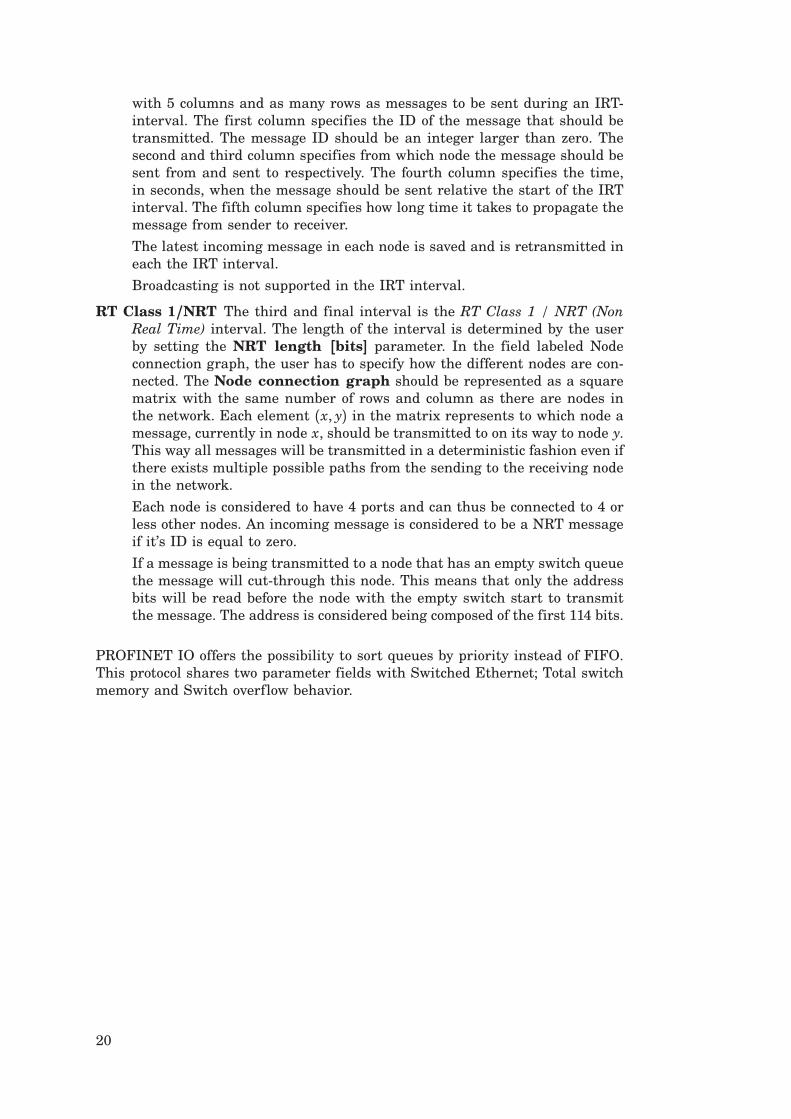
Figure 7 The dialog of the TRUETIME wireless network block.
9. The TrueTime Wireless Network
The usage of the wireless network block is similar to and works in the same wayas the wired one. To also take the path-loss of the radio signals into account,it has x and y inputs to specify the true location of the nodes. Two networkprotocols are supported at this moment: IEEE 802.11b/g (WLAN) and IEEE802.15.4 (ZigBee). Some more technical details about the wireless network canbe found in [Ohlin, 2006]. The radio model used includes support for:
• Ad-hoc wireless networks.
• Isotropic antenna.
• Inability to send and receive messages at the same time.
• Path loss of radio signals modeled as 1da where d is the distance in metersand a is a parameter chosen to model the environment.
• Interference from other terminals.
The wireless network block is configured through the block mask dialog, seeFigure 7. Some parameters can also be set on a per node basis with the commandttSetNetworkParameter. The following parameters are common to all models:
Network type Determines the MAC protocol to be used. Can be either 802.11b/g(WLAN) or 802.15.4 (ZigBee).
21

Network number The number of the network block. The networks must benumbered from 1 and upwards. Wired and wireless networks are not al-lowed to use the same number.
Number of nodes The number of nodes that are connected to the network.This number will determine the size of the Snd, Rcv and Schedule inputand outputs of the block.
Data rate (bits/s) The speed of the network.
Minimum frame size (bits) A message or frame shorter than this will bepadded to give the minimum length. Denotes the minimum frame size,including any overhead introduced by the protocol. E.g., most network pro-tocols have a fixed number of header and tail bits, so the frame must be atleast sizeo f (header) + sizeo f (tail) long.
Transmit power Determines how strong the radio signal will be, and therebyhow long it will reach.
Receiver signal threshold If the received energy is above this threshold, thenthe medium is accounted as busy.
Path-loss exponent The path loss of the radio signal is modeled as 1dawhere
d is the distance in meters and a is a suitably chosen parameter to modelthe environment. Typically chosen in the interval 2-4.
ACK timeout The time a sending node will wait for an ACK message beforeconcluding that the message was lost and retransmit it.
Retry limit The maximum number of times a node will try to retransmit amessage before giving up.
Error coding threshold A number in the interval [0, 1] which defines the per-centage of block errors in a message that the coding can handle. For exam-ple, certain coding schemes can fully reconstruct a message if it has lessthan 3% block errors. The number of block errors are calculated using thesignal-to-noise ratio, where the noise is all other ongoing transmissions.
9.1 802.11b/g (WLAN)
IEEE 802.11b/g is used in many laptops and mobile devices of today. The protocolis based on CSMA/CA with some modifications.
In the simulation, a package transmission is modeled like this: The node thatwants to transmit a packet checks to see if the medium is idle. The transmissionmay proceed, if the medium is found to be idle, and has stayed so for 50 µs. If,on the other hand, the medium is found to be busy, a random back-off time ischosen and decremented in the same way as when colliding (described later inthis section). When a node starts to transmit, its relative position to all othernodes in the same network is calculated, and the signal level in all those nodesare calculated according to the path-loss formula 1
da.
The signal is assumed to be possible to detect if the signal level in the receivingnode is larger than the receiver signal threshold. If this is the case, then thesignal-to-noise ratio (SNR) is calculated and used to find the block error rate(BLER). Note that all other transmissions add to the background noise whencalculating the SNR. The BLER, together with the size of the message, is usedto calculate the number of bit errors in the message and if the percentage of
22
bit errors is lower than the error coding threshold, then it is assumed thatthe channel coding scheme is able to fully reconstruct the message. If there are(already) ongoing transmissions from other nodes to the receiving node and theirrespective SNRs are lower than the new one, then all those messages are markedas collided. Also, if there are other ongoing transmissions which the currentlysending node reaches with its transmission, then those messages may be markedas collided as well.
Note that a sending node does not know if its message is colliding, thereforeACK messages are sent on the MAC protocol layer. From the perspective of thesending node, lost messages and message collisions are the same, i.e., no ACKis received. If no ACK is received during ACK timeout, the message is retrans-mitted after waiting a random back-off time within a contention window. Thecontention window size is doubled for every retransmission of a certain message.The back-off timer is stopped if the medium is busy, or if it has not been idle forat least 50 µs. There are only Retry limit number of retransmissions before thesender gives up on the message and it is not retransmitted anymore.
9.2 802.15.4 (ZigBee)
ZigBee is a protocol designed with sensor and simple control networks in mind. Ithas a rather low bandwidth, but also a really low power consumption. Althoughit is based on CSMA/CA as 802.11b/g, it is much simpler and the protocols arenot the same.
The packet transmission model in ZigBee is similar to WLAN, but the MACprocedure differ and is modeled as:
1. Initialize:NB=0BE=macMinBE
2. Delay for a random number of backoff periods in the interval [0, 2BE − 1]3. Is the medium idle?
if yes: sendelse: goto 4
4. Update the backoff counters:NB=NB+1BE=min(BE+1, aMaxBE)
5. Is NB>macMaxCSMABackoffs?if yes: drop the packetelse: goto 2
The variable names are taken from the standard to make comparisons easier. Asmall explanation of their names is provided below.
NB Number of backoffs.
BE Backoff exponent.
macMinBE The minimum value of the backoff exponent in the CSMA/CA al-gorithm. The default value is 3.
23

aMaxBE The maximum value of the backoff exponent in the CSMA/CA algo-rithm. The default value is 5.
macMaxCSMABackoffs The maximum number of backoffs the CSMA/CA al-gorithm will attempt before declaring a channel access failure. The defaultvalue is 4.
9.3 Calculation of Error Probabilities
During the calculation of error probabilities, it is for simplicity assumed thatBPSK1 is always used in the transmissions. This is of course an approximation,but it relates well to reality.
Assume that a symbol is sent, in our case this is a bit, i.e., a 0 or a 1. Additivewhite Gaussian noise gives a probability density function for the received symbol,that for some signal-to-noise ratio may look like Figure 8. A threshold is thenused to decide if the received symbol is a 0 or a 1. The decision threshold ismarked as a line in the middle of the figure. The darker area to the left of thethreshold gives the probability of a symbol error. A higher signal to noise ratiotranslates the curve to the right, making the probability of error smaller.
The above standard procedure should ideally be performed for every bit in themessage. The total number of calculated bit errors should then be comparedto the error coding threshold. This is, however, not done, because it would bevery computationally expensive. Instead, the maximum noise level during thetransmission is saved, and used to calculate the worst case SNR. By assumingthat bit errors in a message are uncorrelated, it is deduced that the numberof bit errors, X , belongs to a binomial distribution X ∈ Bin(n, p), where nis the number of bits in the message, and p is the probability that a certainbit is erroneous. If the value of n is large, the binomial distribution can beapproximated with a normal distribution, using the central limit theorem. Thisgives that X ∈ N(np,√npq) where q = 1− p. What we are really interested inis the probability that bn, where b is the error coding threshold, is larger thanthe total number of bit errors in a message. This probability is calculated using
P(X ≤ bn) =
Φ(bn− np√npq
) if bn− np > 0
1− Φ( pbn− npp√npq
) if bn− np ≤ 0
where Φ is the standard normal cumulative distribution function.
Example Assume that a message consists of 100 bits, i.e., n = 100. The prob-ability that a certain bit is erroneous has been calculated to 0.1 using the abovemethod, i.e., p = 0.1 and q = 1 − p = 0.9. The error coding threshold has beenset to 5%, i.e., b = 0.05. Then the probability that we can decode the completemessage is
P(X ≤ bn) = 1− Φ( pbn− npp√npq
) = 1− Φ( 5√9) ( 0.0478
1Binary Phase Shift Keying (BPSK) is a means of transmitting symbols by altering the phaseof a reference signal. It uses two phases separated by 180○ and is hence binary.
24

0
0.05
0.1
0.15
0.2
0.25
0.3
0.35
0.4
Figure 8 Probability density function for a received symbol when using binary phaseshift keying and additive white Gaussian noise. The line in the middle is the decisionthreshold. The area to the left of the threshold gives the probability of an erroneousdecision. The area to the right gives the probability of a correct decision.
9.4 User-Defined Path-Loss Function
The default path-loss function (or propagation model) used in the TrueTimewireless simulations is
Preceiver =1daPsender
where P is the power, d is the distance in meters, and a is a parameter that canbe chosen to model different environments. This model is often used in simula-tions, but in some cases it can be advantageous to use other models. TrueTimehas the possibility to register a user-defined path-loss function. The function iswritten as a Matlab function (M-file or MEX-function) and can therefore takeadvantage of all the built-in functions available in Matlab. In particular, thisincludes the possibility to use persistent variables, i.e., variables which are re-tained in memory between calls to the function. The function can, for example,be used to model a Rayleigh2 fading or the blocking of radio signals to and fromcertain points in the environment. At the moment, nodes in the TrueTime frame-work only have x and y coordinates, but if a direction was to be introduced thisfunction could also be used to model directive effects in the antenna behaviour.
The Matlab function takes the following arguments
• Transmission power
• Name of the sending node
• x and y coordinates of the sending node
• Name of the receiving node
• x and y coordinates of the receiving node
• Current simulation time2In a Rayleigh fading, the relative speed of two nodes and the number of multiple paths that
the signal takes from the sender to the receiver is taken into account. See Figure 9 for an example.
25

0 100 200 300 400 500 600 700 800 900 100010
−2
10−1
100
101
db
sample
Rayleigh fading
Figure 9 Example of a Rayleigh fading using a radio frequency of 2.4 MHz. Nodes mov-ing with a relative speed of 6 km/h, 1 second sampling interval and 10 random phasers.
and returns the signal power in the receiving node.
A small example showing the structure of how a Rayleigh fading could be imple-mented can be seen in Listing 6.
To increase simulation speed, it is recommended to implement the Matlab func-tion as a C MEX-function.
Listing 6 Example of path-loss function modeling Rayleigh fading.
function power = rayleigh(transmitPower, node1, x1, y1, node2, x2, y2, time)
% Calculate the exponential pathloss
distance = sqrt((x1 - x2)^2 + (y1 - y2)^2);
power = transmitPower/(distance+1)^3.5;
% Kalman filter to get the relative velocity of the two nodes
velocity = kalman_velocity(node1, x1, y1, node2, x2, y2, time);
% Calculate the rayleigh fading
factor = calculate_rayleigh(node1, node2, velocity, time);
% Add the rayleigh fading to the exponential path loss
power = power * factor;
26

10. The TrueTime Battery
The battery block has one parameter, the initial power, which can be set usingthe configuration mask. To use the battery, enable the check box in the kernelconfiguration mask and connect the output of the battery to the E input of thekernel block. Connect every power drain such as the P output of the kernel block,ordinary Simulink models, and the wireless network block to the P input of thebattery. The battery uses a simple integrator model, so it can be both chargedand recharged.
Note that the kernel will not execute any code if it is configured to use batteriesand the input P to the kernel block is zero. See the example in Section 12.4 belowfor more details on the use of TRUETIME batteries.
11. The TrueTime Standalone Network Blocks
The standalone network blocks, named TrueTime Send and TrueTime Receive,as seen in Figure 1, can be used to send messages using the network blockswithout using kernel blocks. This makes it possible to create TrueTime networksimulations without having to initialize kernels, create and install interrupt han-dlers, etc. It is in other words possible to create a whole network simulation inSimulink without any M-files at all. It is also possible to mix these blocks withkernel blocks, so that some stations use the standalone network blocks, whileothers use the standard ttSend and ttGetMsg primitives from within a codefunction executing in a kernel block.
The standalone network blocks are configured through the block mask dialogs,seen in Figure 10. The parameters are the same that are used in the True-Time Send and TrueTime Receive primitives. The TrueTime Send block hasa Simulink trigger input port, which can be configured to trigger on raising,falling or either flanks. The ttGetMsg block has an optional trigger output port.The value of the trigger output switches back and forth between 0 and 1 as mes-sages are received. This port can be used to trigger something that should beexecuted after a new message has been received.
12. Examples
The directory $DIR/examples contains ten examples:
simple Several different ways of implementing a simple periodic con-troller are demonstrated. Both M-file and C++ implementa-tions are provided.
threeservos Illustrates task scheduling and control, where three periodiccontrol tasks execute on the same CPU. Both M-file and C++implementations are provided.
networked Demonstrates networked control involving four computernodes and the wired network block. Both M-file and C++implementations are provided, as well as an implementationusing the stand-alone network interface blocks.
27

wireless Demonstrates wireless networked control with transmissionpower control to minimize the energy consumption. M-fileimplementation only.
AODV Illustrates how higher-layer communication protocols suchas AODV routing can be implemented in TRUETIME. M-fileimplementation only.
soccer A larger example showing simulation and animation of tenmobile robots playing soccer. M-file implementation only.
RUNES_demo A very large example with mobile robot navigation through asensor network using ultrasound trilateration. C++ imple-mentation only.
The first three examples are provided in both Matlab and C++ versions. However,the descriptions below will only treat the Matlab case. For detailed instructionson how to compile the examples, see the README-files in the correspondingexample directories.
12.1 PID-control of a DC-servo
Introduction The first example considers simple PID control of a DC-servoprocess, and is intended to give a basic introduction to the TRUETIME simulationenvironment. The process is controlled by a controller task implemented in aTRUETIME kernel block. Four different implementations of the controller task areprovided to show different ways to implement periodic activities. The files arefound in the directory $DIR/examples/simple/matlab.
Process and Controller The DC-servo is described by the continuous-timetransfer function
G(s) = 1000s(s+ 1) (1)
The PID-controller is implemented according to the following equations
P(k) = K ⋅ (β r(k) − y(k))
I(k+ 1) = I(k) + KhTi(r(k) − y(k))
D(k) = adD(k− 1) + bd(y(k− 1) − y(k))u(k) = P(k) + I(k) + D(k)
(2)
where ad = TdNh+Td and bd =
NKTdNh+Td , see [Åström and Hägglund, 1995]. The
controller parameters were chosen to give the system a closed-loop bandwidth ofω c = 20 rad/s and a relative damping of ζ = 0.7.
Simulation Files The initialization script (servo_init.m) is given in an ab-breviated version in Listing 7. As seen in the initialization script, it is possible tochoose between four different implementations of the periodic control task. Theyare specified by the init function parameter in the kernel block dialog.
28

Figure 10 The dialog of the TrueTime Send block to the left, and the dialog of theTrueTime Receive block to the right.
• Implementation 1: Uses the TRUETIME built-in support for periodic tasks,and the code function is given in the file pidcode1.m.
• Implementation 2: Also uses the TRUETIME built-in support for periodictasks, but the computation of the control signal in each sample is doneby calling a Simulink block diagram. The code function is given in the filepidcode2.m. Since all the controller parameters and states are contained inthe Simulink block, the task data (data2) only consist of the control signal,u.
• Implementation 3: Implements the periodic task by using the TRUETIMEprimitive ttSleepUntil. The code function is given in the file pidcode3.m.
• Implementation 4: Implements the periodic task by using a periodic timer.The associated interrupt handler samples the process and triggers taskjobs. The handler and controller task communicate using a mailbox. Thecode functions for the handler and controller are given in the files sampler
code.m and pidcode4.m, respectively.
Simulations The Simulink model is called servo.mdl and is given in Fig-ure 11. Open the Simulink model and try the following
• Run a simulation and verify that the controller behaves as expected. No-tice the computational delay of 2 ms in the control signal. Compare withthe code function, pidcode1.m. Study the schedule plot (high=running,medium=ready, low=idle).
29

• Try changing the execution time of the first segment of the code function,to simulate the effect of different input-output delays.
• Change the sampling period and study the resulting control performance.
• A PID-controller is implemented in the Simulink block controller.mdl.Change the init function parameter of the kernel block from 1 to 2, sothat implementation 2 is used instead of 1. Study the corresponding codefunction, pidcode2.m. This code function is using the Simulink block tocompute the control signal in each sample.
• Change to implementation 3 and run a simulation. Study the code function,
Listing 7 The initialization script for the PID-control example.
function servo_init(mode)
ttInitKernel(2, 1, ’prioFP’); % nbrOfInputs, nbrOfOutputs, fixed priority
period = 0.006;
deadline = period;
offset = 0.0;
prio = 1;
data.K = 0.96;
... % more task data
switch mode,
case 1,
% IMPLEMENTATION 1: using the built-in support for periodic tasks
%
ttCreatePeriodicTask(’pid_task’,offset,period,prio,’pidcode1’,data);
case 2,
% IMPLEMENTATION 2: calling Simulink block within code function
%
data2.u = 0;
ttCreatePeriodicTask(’pid_task’,offset,period,prio,’pidcode2’,data2);
case 3,
% IMPLEMENTATION 3: sleepUntil and loop back
data.t = 0;
ttCreateTask(’pid_task’,deadline,prio,’pidcode3’,data);
ttCreateJob(’pid_task’);
case 4,
% IMPLEMENTATION 4: sampling in timer handler, triggers task job
hdl_data.yChan = 2;
ttCreateInterruptHandler(’timer_handler’,prio,’samplercode’,hdl_data);
ttCreatePeriodicTimer(’timer’,offset,period,’timer_handler’);
ttCreateMailbox(’Samples’,10);
ttCreateTask(’pid_task’,deadline,prio,’pidcode4’,data);
end
30

Figure 11 The TRUETIME model of the DC-servo system.
pidcode3.m.
• Change to implementation 4 and run a simulation. Study the code func-tions, samplercode.m and pidcode4.m. Notice the inclusion of the handlerin the schedule plot.
12.2 Task Scheduling and Control
Introduction This example extends the simple PID control example from theprevious section to the case of three PID-tasks running concurrently on the sameCPU controlling three different DC-servo systems. The effect of the schedulingpolicy on the global control performance is demonstrated. The files are found inthe directory $DIR/examples/threeservos/matlab.
Simulations Open the Simulink model threeservos.mdl and try the following
• Make sure that rate-monotonic scheduling is specified by the functionttInitKernel in the initialization script (threeservos_init.m) and simu-late the system. Study the computer schedule and the control performance.Task 1 will miss all its deadlines and the corresponding control loop isunstable.
• Change the scheduling policy to earliest-deadline-first (change ’prioRM’ to’prioEDF’) and run a new simulation. Again study the computer schedule
31

Figure 12 The TRUETIME model of the networked control system.
and the control performance. After an initial transient all tasks will misstheir deadlines, but still the overall control performance is satisfactory.
12.3 Networked Control System
Introduction This example simulates networked control of the DC-servo ofEquation (1). The example contains four computer nodes, each represented by aTRUETIME kernel block. A time-driven sensor node samples the process periodi-cally and sends the samples over the network to the controller node. The controltask in this node calculates the control signal and sends the result to the ac-tuator node, where it is subsequently actuated. The simulation also involves aninterfering node sending disturbing traffic over the network, and a disturbinghigh-priority task executing in the controller node. The files are found in thedirectory $DIR/examples/networked/matlab.
Simulations The Simulink model is called networked.mdl and is given inFigure 12. Open the Simulink model and try the following
• Study the initialization scripts and code functions for the different nodes.The event-driven nodes contain interrupt handlers, which are activated asmessages arrive over the network. The handler then triggers the task thatwill read and process the message.
• Run a first simulation without disturbing traffic and without interferencein the controller node. This is obtained by setting the variable BWshare inthe code function of the interfering node (interfcode.m) to zero, and bycommenting out the creation of the task ’dummy’ in controller_init. Inthis case we will get a constant round-trip delay and satisfactory control
32

performance. Study the network schedule (high=sending, medium=waiting,low=idle) and the resulting control performance.
• Switch on the disturbing node and the interfering task in the controllernode. Set the variable BWshare to the percentage of the network bandwidthto be used by the disturbing node. Again study the network schedule and theresulting control performance. Experiment with different network protocolsand different scheduling policies in the controller node.
12.4 Wireless Control System with Automatic Gain Control
Introduction This example shows networked control of a DC-servo describedby Equation (1) using communication over a wireless network. The example alsoshows how to simulate power consumption and how to use the battery block.The model contains two computer nodes located 20 m apart, each representedby a TRUETIME kernel and battery block. A time-driven sensor/actuator nodesamples the process periodically and sends the samples over the network to thecontroller node. The control task in this node calculates the control signal andsends the result back to the sensor/actuator node, where it is actuated. Thewireless communication link is at the same time subject to a simple power controlscheme. Power control tasks running in both the sensor/actuator node and in thecontroller node periodically send out ping messages to the other node to test thechannel transmission. If a reply is received, the channel is assumed to be goodand the transmission power is lowered. If on the other hand no reply is received,then the transmission power is considerably increased until it saturates or a replyis received again. The files are found in the directory $DIR/examples/wireless.
Simulations Open the model wireless.mdl to run the simulation.
• Run a first simulation without modifying anything. Look at the plots show-ing the battery levels in the two nodes. Note that the power control schemeis not activated until 2 seconds have elapsed. Also note how the measuredvalues at some times deviate more than usual from the reference values.This deviation is caused by the fact that it is possible to lose several con-secutive sensor value readings when using the simple power control that isimplemented in the nodes.
• Switch off the power control scheme in the controller node. This is doneby commenting out the creation of the task power_controller_task incontroller_init. Run the simulation again and now note that the powerdrain is constant in the controller node. This causes the battery to run outof energy and the control is lost.
• Experiment with different network parameters and protocols and see howit affects the control behaviour. In this example, the kernel block is setto consume 10 mW. This can easily be changed by using the commandttSetKernelParameter. This command can also be used to set the CPUscaling factor to enable Dynamic Voltage Scaling.
33

12.5 Wireless Ad-hoc Routing Using AODV
Introduction The TRUETIME wireless network simulates communication inan ad-hoc network, i.e., no centralized access point or infrastructure exists tocoordinate the traffic across the network. In such networks it is necessary toimplement decentralized functionality to be able to route the traffic over thenetwork. This example describes a TRUETIME implementation of one such ad-hocwireless routing protocol.
AODV [Perkins and Royer, 1999] stands for Ad-hoc On-Demand Distance Vectorrouting and contrary to most routing mechanisms, it does not rely on periodictransmission of routing messages between the nodes. Instead, routes are createdon-demand, i.e., only when actually needed to send traffic between a source and adestination node. This leads to a substantial decrease in the amount of networkbandwidth consumed to establish routes. Below follows a brief description ofthe functionality of AODV. For a complete definition of the AODV protocol, see[Perkins and Royer, 2003].
AODV uses three basic types of control messages in order to build and invalidateroutes: route request (RREQ), route reply (RREP), and route error (RERR) mes-sages. These control messages contain source and destination sequence numbers,which are used to ensure fresh and loop-free routes.
A node that requires a route to a destination node initiates route discovery bybroadcasting an RREQ message to its neighbors. A node receiving an RREQstarts by updating its routing information backwards towards the source. If thesame RREQ has not been received before, the node then checks its routing tablefor a route to the destination. If a route exists with a sequence number greaterthan or equal to that contained in the RREQ, an RREP message is sent backtowards the source. Otherwise, the node rebroadcasts the RREQ. When an RREPhas propagated back to the original source node, the established route may beused to send data. Periodic hello messages are used to maintain local connectiviyinformation between neighboring nodes. A node that detects a link break willcheck its routing table to find all routes which use the broken link as the nexthop. In order to propagate the information about the broken link, an RERRmessage is then sent to each node that constitute a previous hop on any of theseroutes.
The files for this tutorial example are found in the directory $DIR/examples/AODV.All nodes are initialized using the same initialization script, node_init.m. TwoTRUETIME tasks are created in each node to handle AODV send and receive ac-tions, respectively. The AODV send task is activated from the application codeas a data message should be sent to another node in the network. The AODVreceive task handles incoming AODV control messages and forwarding of datamessages. Communication between the application layer and the AODV layer ishandled using TRUETIME mailboxes.
The AODV send task (AODVsendcode.m) operates according to the following code:
IF (data message received from application)
check the routing table for a route to the destination;
IF (a valid route exists)
forward data message to next hop on route;
update expiry time of route entry;
34

ELSE
initiate route discovery by broadcasting RREQ message;
buffer data message until route has been established;
END
ELSE IF (notified of established new route)
send all buffered data messages to destination
END
The AODV receive task (AODVrcvcode.m) performs the following:
IF (receiving data message)
update expiry timer for reverse route entry to source;
IF (this node is the destination)
Pass data message to application;
ELSE
forward data message to next hop on route;
update expiry timer of route entry;
END
ELSE
SWITCH message_type
CASE RREQ:
IF (first time this RREQ is received)
enter RREQ in cache;
create or update route entry to source;
check the routing table for a route to the destination;
IF (a route exists)
send RREP message back towards source;
ELSE
update and rebroadcast the RREQ;
END
END
CASE RREP:
check the routing table for a route to the destination;
IF (no route exists)
create route entry to destination;
ELSE IF (route entry exists but should be updated)
update route entry to destination;
END
IF (this node is the original source)
notify the AODV send task about the new route;
ELSE IF (route to destination was created or updated)
update reverse route entry towards source;
propagate RREP to next hop towards source;
END
CASE RERR:
find and invalidate all affected route entries;
propagate the RERR to all previous hops on the routes;
END
END
Each node also contains a periodic task (hellocode.m), responsible for broad-casting hello messages and determine local connectivity based on hello messagesreceived from neighboring nodes. Finally, each node has a task to handle timerexpiry of route entries (expcode.m).
35

Simulations Open the model AODV.mdl to run the simulation.
• The simulation example consists of seven nodes. Choose the option UpdateDiagram in the Edit menu to bring up an animation window of the sim-ulation. This will show the original positions of the seven nodes and theirrespective signal reach.
• Run a simulation. In the simulation scenario, the left-most node (node 1)sends data periodically to node 7 with period 0.5. The initial route that isestablished is 1 → 3 → 5 → 7. At time t = 3, node 5 starts to move whicheventually leads to the route breaking. At time t = 10, node 6 repairs theroute by moving in between node 4 and 7. The printouts in the Matlabcommand window describe the actions in the AODV layer in more detail.Also study the global variable routing_table.
• Open and examine the file initsim.m. This file initializes the global vari-ables used in the simulation, e.g., the routing table and the node positions.By changing the variable verbose from 0 to 1 even more detailed AODVinformation will be displayed when the simulation is run.
• The global variables sent and received show the data that is sent (by node1) and received (by node 7) in the simulation. Examine the lengths of thesevectors to determine how many messages that where lost due to the delayin detecting and propagating the information about the broken link backto the source node. (Answer: The messages sent at times 8.0002, 8.5002,and 9.0002 are lost.)
• The hello interval determines who fast the network will respond to brokenlinks (and also the bandwidth overhead). Try changing the AODV param-eter HELLO_INTERVAL (both in initsim.m and node_init.m) to decrease thenumber of lost data messages. In this case only two messages are lost.
12.6 Mote Soccer
This largely undocumented example features a slighly more complex simulationset-up where ten mobile robots are playing soccer. The robots and the ball areanimated during the simulation, see Figure 13. The simulation files are foundin the directory $DIR/examples/soccer.
Each mobile robot (mote) is modeled using a kernel block and two integratorsrepresenting the x and y coordinates of the robot. The ball is modeled as a forth-order system (an integrator plus damping in each direction) implemented inan S-function (ballmotion.m). This S-function also handles the player interac-tion with the ball. The robots within each team communicate over the wirelessnetwork. The goalkeeper is each team acts as the “master” and coordinates theplayers.
The mask of the network block is programmed to dynamically change the con-tents of the underlying subsystem (study the initialization commands). This isa very conventient feature when working with a large number of network nodes.
13. Kernel Implementation Details
This section will give a brief description of the implementation of the TRUETIMEkernel. The main data structures will be described as well as the kernel imple-
36

Figure 13 Mote soccer.
mentation. It will also be described how the event-based kernel simulation isachieved in Simulink, using the zero-crossing detection mechanism.
13.1 Kernel Data Structures
The main data structure of the TRUETIME kernel is a C++ class called RTsys,see $DIR/kernel/ttkernel.h. An instance (rtsys) of this class is created in theinitialization step of the kernel S-function. The rtsys object is stored in theUserData field of the kernel block between simulation steps. Among others, theRTsys class contains the following attributes:
class RTsys {
public:
double time; // Current time in simulation
double* inputs; // Vector of input port values
double* outputs; // Vector of output port values
Task* running; // Currently running task
List* readyQ; // usertasks and handlers ready for execution, prio-sorted
List* timeQ; // usertasks and timers waiting for release, time-sorted
List* taskList; // A list containing all created tasks
List* handlerList;
List* monitorList;
List* eventList;
37

double (*prioFcn)(Task*); // Priority function
};
The ready queue and time queue are sorted linked list. The elements in the timequeue (tasks and timers) are sorted according to release times and expiry times.A timer in the time queue is actually represented by its corresponding han-dler. The tasks in the ready queue are sorted according to the priority functionprioFcn, which is a function that returns a (possibly dynamic) priority num-ber from a Task instance, see the description of ttInitKernel in the commandreference.
The Task class ($DIR/kernel/task.h) inherits from the node class of the linkedlist ($DIR/kernel/linkedlist.h) and contains the following basic attributes:
class Task : public Node {
public:
char* name;
int segment; // the current segment of the code function
double execTime; // the remaining execution time of the current segment
void *data; // task data (C++ case)
char* dataMatlab; // name of global variable for task data (Matlab case)
double (*codeFcn)(int, void*); // Code function (C++ case)
char* codeFcnMatlab; // Name of m-file code function (Matlab case)
};
The exectime of the running task is updated each time the kernel executes, seeListing 8. When it has reached zero, the next segment of the code function isexecuted. The task data in the Matlab case is represented as a name of a uniqueglobal variable. The code function of a task is represented either as a functionpointer in the C++ case or the name of a Matlab m-file.
User tasks and interrupt handlers are both subclasses to Task and containthe attributes given below, among others. See $DIR/kernel/usertask.h and$DIR/kernel/handler.h for complete descriptions.
class UserTask : public Task {
public:
double priority;
double wcExecTime;
double deadline;
double absDeadline;
double release; // task release time if in timeQ
double budget;
int state; // Task state (IDLE; WAITING; SLEEPING; READY; RUNNING)
double tempPrio; // temporarily raised prio value
List *pending; // list of pending jobs
InterruptHandler* deadlineORhandler; // deadline overrun handler
InterruptHandler* exectimeORhandler; // execution-time overrun handler
38

int nbrOfUserLogs; // Number of user-created log entries
Log* logs[NBRLOGS];
void (*arrival_hook)(UserTask*); // hooks
void (*release_hook)(UserTask*);
void (*start_hook)(UserTask*);
void (*suspend_hook)(UserTask*);
void (*resume_hook)(UserTask*);
void (*finish_hook)(UserTask*);
};
The kernel implements priority inheritance to avoid priority inversion. Thereforeeach task has a dynamic priority value that may be raised while executing insidea monitor. Pending jobs are stored in the job queue of the task sorted by releasetime. See $DIR/kernel/log.h for the contents of the Log class.
class InterruptHandler : public Task {
public:
double priority;
int type; // {UNUSED, OVERRUN, TIMER, NETWORK, EXTERNAL}
UserTask *usertask; // if overrun handler to task
Timer* timer; // if associated with timer interrupt
Network* network; // if associated with network receive interrupt
Trigger* trigger; // if associated with external interrupt
int pending; // list of pending invocations, if new external
// interrupt occurs before the old is served
};
See the corresponding header files in $DIR/kernel for the specifications of theclasses Timer, Network, and Trigger.
13.2 Task Model
TRUETIME user tasks may be periodic or aperiodic. Aperiodic tasks are triggeredby the creation of task jobs, using the command ttCreateJob. All pending jobsare inserted in a job queue of the task sorted by release time. For periodic task(created by the command ttCreatePeriodicTask), an internal timer is set up toperiodically create jobs for the task.
Apart from its code function, each task is characterized by a number of attributes.The static attributes of a task include
• a relative deadline
• a priority
• a worst-case execution time
• a period (if the task is periodic)
39

These attributes are kept constant throughout the simulation, unless explicitlychanged by the user (see ttSetX in the command reference).In addition to these attributes, each task job has dynamic attributes associatedwith it. These attributes are updated by the kernel as the simulation progresses,and include
• an absolute deadline
• a release time
• an execution time budget (by default equal to the worst-case execution timeat the start of each task job)
• the remaining execution time
These attributes (except the remaining execution time) may also be changed bythe user during simulation. Depending on the scheduling policy, the change of anattribute may lead to a context switch. E.g., if the absolute deadline is changedand earliest-deadline-first scheduling is simulated.
In accordance with [Bollella et al., 2000] it is possible to associate two interrupthandlers with each task: a deadline overrun handler (triggered if the task missesits deadline) and an execution time overrun handler (triggered if the task exe-cutes longer than its worst-case execution time). These handlers can be used toexperiment with dynamic compensation schemes, handling missed deadlines orprolonged computations. Overrun handlers are attached to tasks with the com-mands ttAttachDLHandler and ttAttachWCETHandler. See the tutorial examplein Section ?? for an example on how to use overrun handlers.
Furthermore, to facilitate arbitrary dynamic scheduling mechanisms, it is possi-ble to attach small pieces of code (hooks) to each task. These hooks are executedat different stages during the simulation, as shown in Figure 14. Usually thearrival and release of a task job coincide. The exception is when a job is createdwhile previous jobs have yet to finish. In that case, the arrival hook is executedimmediately (at the call of ttCreateJob) and the release hook is called when thejob is subsequently released from the job queue.
The hooks can, e.g., be used to monitor different scheduling schemes and keeptrack of context switches and deadline overruns. By default, the hooks implementlogging, simulation of context switching, and contain code to trigger the worst-case execution time and deadline overrun handlers possibly associated with thedifferent tasks. For the default hook implementation, see $DIR/kernel/default
hooks.cpp.
13.3 The Kernel Function
The functionality of the TRUETIME kernel is implemented by the functionrunKernel located in $DIR/kernel/ttkernel.cpp. This function manipulates thebasic data structures of the kernel, such as the ready queue and the time queue,and is called by the Simulink call-back functions at appropriate times duringthe simulation. See Section 13.4 for timing implementation details.
It is also from this function that the code functions for tasks and interrupthandlers are called. The kernel keeps track of the current segment and updates
40

τ
t
Arrival, Releasehooks
Starthook
Suspendhook
Resumehook
Finishhook
Figure 14 Scheduling hooks.
it when the time associated with the previous segment has elapsed. The hooksmentioned above are also called from this function.
A simple model for how the kernel works is given by the pseudo code in Listing 8.This code focuses on user tasks. See $DIR/kernel/ttkernel.cpp for the completeimplementation.
13.4 Timing
The TRUETIME blocks are event-driven and support external interrupt handling.Therefore, the blocks have a continuous sample time. Discrete (i.e., piecewiseconstant) outputs are obtained by specifying FIXED_IN_MINOR_STEP_OFFSET:
static void mdlInitializeSampleTimes(SimStruct *S) {
ssSetSampleTime(S, 0, CONTINUOUS_SAMPLE_TIME);
ssSetOffsetTime(S, 0, FIXED_IN_MINOR_STEP_OFFSET);
}
The timing of the block is implemented using a zero-crossing function. As wesaw above, the next time the kernel should wake up (e.g., because a task is tobe released from the time queue or a task has finished its execution) is denotednextHit. If there is no known wake-up time, this variable is set to infinity. Thebasic structure of the zero-crossing function is
static void mdlZeroCrossings(SimStruct *S) {
Store all inputs;
if (any interrupt input has changed value) {
nextHit = ssGetT(S);
}
ssGetNonsampledZCs(S)[0] = nextHit - ssGetT(S);
}
This will ensure that mdlOutputs executes every time an internal or externalevent has occurred. Since several kernel and network blocks may be connected ina circular fashion, direct feedthrough is not allowed. We exploit the fact that, whenan input changes as a step, mdlOutputs is called, followed by mdlZeroCrossings.Since direct feedthrough is not allowed, the inputs may only be checked forchanges in mdlZeroCrossings. There, the zero-crossing function is changed sothat the next major step occurs at the current time. This scheme will introducea small timing error (< 10−15 s).
41

The kernel function (runKernel()) is only called from mdlOutputs since this iswhere the outputs (D/A, schedule, network) can be changed. The timing imple-mentation implies that zero-crossing detection must be turned on (this is default,and can be changed under Simulation Parameters/Advanced).
14. TrueTime Command Reference
The available TRUETIME commands are summarized in Tables 2–4, and the rest ofthe manual contains detailed descriptions of their functionality. The commandsare categorized according to their intended use (I; initialization script, T; taskcode function, and H; interrupt handler code function). Note that the set and getprimitives are collected under the headings ttSetX and ttGetX, respectively.
By typing help command, where command is the name of a TRUETIME function, inthe Matlab command window, the syntax of the various TRUETIME functions willbe displayed.
42

Listing 8 Pseudo code for the TRUETIME kernel function.
double runKernel(void) {
timeElapsed = rtsys->time - rtsys->prevHit; // time since last invocation
rtsys->prevHit = rtsys->time; // update previous invocation time
nextHit = 0.0;
while (nextHit == 0.0) {
// Count down execution time for current task
// and check if it has finished its execution
if (there exists a running task) {
task->execTime -= timeElapsed;
if (task->execTime == 0.0) {
task->segment++;
task->execTime = task->codeFcn(task->segment, task->data);
if (task->execTime < 0.0) {
// Negative execution time = task finished
task->execTime = 0.0;
task->segment = 0;
Remove task from readyQ;
task->finish_hook(task);
if (job queue is non-empty)
Release next job and execute release-hook ;
}
}
} // end: counting down execution time of running task
// Check time queue for possible releases (user tasks or timers)
for (each task) {
if ((release time - rtsys->time) == 0.0) {
Move task to ready queue
}
} // end: checking timeQ for releases
// Determine task with highest priority and make it running task
newrunning = rtsys->readyQ->getFirst();
oldrunning = rtsys->running;
if (oldrunning is being suspended) {
oldrunning->suspend_hook(oldrunning);
}
if (newrunning is being resumed or started) {
if (newrunning->segment == 0) {
newrunning->start_hook(newrunning);
} else {
newrunning->resume_hook(newrunning);
}
} // end: task dispatching
// Determine next invocation of kernel function
time1 = remaining execution time of current task;
time2 = next release time of a task from the time queue
nextHit = min(time1, time2);
} // end: loop while nextHit == 0.0
return nextHit;
}
43

Table 2 Commands used to create and initialize TRUETIME objects, and to control thesimulation.
Command Description
ttInitKernel Initialize the kernel, specifying the scheduling policy.ttGetInitArg (C++ only) Retrieve the init argument from the block dialogue.ttCreateTask Create an aperiodic task.ttCreatePeriodicTask Create a periodic task.ttCreateLog Create a log structure and specify data to log.ttCreateHandler Create an interrupt handler.ttCreateMonitor Create a monitor (mutex) for protection of shared data.ttCreateEvent Create an event (condition variable).ttCreateMailbox Create a mailbox for inter-task communication.ttCreateSempahore Create a counting semaphore.ttCreateCBS Create a soft or hard constant bandwidth server.ttNoSchedule Switch off the schedule plot for a specific task or
interrupt handler.ttNonPreemptible Make a task non-preemptible.ttAttachTriggerHandler Attach an interrupt handler to an external trigger.ttAttachNetworkHandler Attach an aperiodic task or interrupt handler to a
network interface.ttAttachDLHandler Attach a deadline overrun handler to a task.ttAttachWCETHandler Attach a worst-case execution time overrun interrupt
handler to a task.ttAttachHook (C++ only) Attach a kernel scheduling hook to a task.ttAttachCBS Attach a task to a constant bandwidth server.ttAbortSimulation Abort the simulation.
44

Table 3 Commands used to set and get task or kernel attributes.
Command Description
ttSetPeriod Set the period of a periodic task.ttSetDeadline Set the relative deadline of a task.ttSetPriority Set the priority of a task.ttSetWCET Set the worst-case execution (maximum budget) time of a
task.ttSetData Update the local memory data structure of a task.ttSetAbsDeadline Set the absolute deadline of the current job.ttSetBudget Set the execution time budget of the current job.ttSetUserData Set arbitrary kernel user data (C++ only).ttGetPeriod Get the period of a periodic task.ttGetDeadline Get the relative deadline of a task.ttGetPriority Get the priority of a task.ttGetWCET Get the worst-case execution time of a task.ttGetData Retrieve the local memory data structure of a task.ttGetRelease Get the release time of the current job.ttGetAbsDeadline Get the absolute deadline the current job.ttGetBudget Get the execution-time budget of the current job.ttSetUserData Set the kernel user data (C++ only).ttGetUserData Get the kernel user data (C++ only).ttSetCBSParameters Set the parameters of a constant bandwidth server.
45

Table 4 Real-time primitives.
Command Description
ttCreateJob Create a job of a task.ttKillJob Kill the running (ready) job of a task, if any.ttEnterMonitor Enter a monitor (blocking).ttExitMonitor Exit a monitor.ttWait Wait for an event (blocking).ttNotify Notify the highest-priority task waiting for an event.ttNotifyAll Notify all tasks waiting for an event.ttLogStart Start a timing measurement for a log.ttLogStop Stop a timing measurement and save in the log.ttLogNow Log the current time.ttLogValue Log a scalar value.ttTryPost Post a message to a mailbox (non-blocking).ttTryFetch Fetch a message from a mailbox (non-blocking).ttPost Post a message to a mailbox (blocking).ttFetch Fetch a message from a mailbox (blocking).ttRetrieve Read the actual message fetched from a mailbox.ttTake Take a semaphore.ttGive Give a semaphore.ttCreateTimer Create a one-shot timer and associate an interrupt
handler with the timer.ttCreatePeriodicTimer Create a periodic timer and associate an interrupt
handler with the timer.ttRemoveTimer Remove a specific timer.ttCurrentTime Get and/or set the current time in the simulation on a
per node basis.ttSleepUntil Sleep until a certain point in time.ttSleep Sleep for a certain amount of time.ttAnalogIn Read a value from an analog input channel.ttAnalogOut Write a value to an analog output channel.ttSetNextSegment Set the next segment to be executed in the code
function (to implement loops and branches).ttGetInvoker Get the name of the external trigger, network interface,
or overrun timer that triggered running handler.ttCallBlockSystem Call a Simulink block diagram from within a code
function.ttSendMsg Send a message over a TRUETIME network
(non-blocking).ttGetMsg Get a message that has been received over a TRUETIME
network (non-blocking).ttDiscardUnsentMessages Delete any unsent messages.ttSetNetworkParameter Set a specific network parameter on a per node basis.ttSetKernelParameter Set a specific kernel parameter on a per node basis.
46

ttAbortSimulation (TH)
Purpose
Stop the current simulation, raising an error.
Matlab syntax
ttAbortSimulation
C++ syntax
ttAbortSimulation()
Description
This function is used to abort a simulation before the simulation stop-time hasbeen reached. For instance, after a certain condition has occurred, it may bepointless to continue the simulation.
If you run repeated simulations in a script, since this primitive generates anerror, it may be useful to start the simulation from within a try statement:
for i=1:10
try
sim(’mymodel’)
catch
end
end
47
ttAnalogIn (TH)
Purpose
Read a value from an analog input channel.
Matlab syntax
value = ttAnalogIn(inpChan)
C++ syntax
double ttAnalogIn(int inpChan)
Arguments
inpChan The input channel to read from.
Description
This function is used to read an analog input from the environment. The inputchannel must be between 1 and the number of analog inputs specified in thekernel block dialogue.
See Also
ttAnalogOut
48

ttAnalogOut (TH)
Purpose
Write a value to an analog output channel. The value is held between updates.
Matlab syntax
ttAnalogOut(outpChan, value)
C++ syntax
void ttAnalogOut(int outpChan, double value)
Arguments
outpChan The output channel to write to.value The value to write.
Description
This function is used to write an analog output to the environment. The outputchannel must be between 1 and the number of analog outputs specified in thekernel block dialogue.
See Also
ttAnalogIn
49

ttAttachCBS (I)
Purpose
Attach a task to a constant bandwidth server (CBS).
Matlab syntax
ttAttachCBS(taskname, CBSname)
C++ syntax
void ttAttachCBS(char *taskname, char *CBSname)
Arguments
taskname The name of the task.CBSname The name of the constant bandwidth server.
Description
This function is used to associate a task with a constant bandwidth server. Manytasks may be associated with the same CBS. Note the CBSs can only be createdunder EDF scheduling. A task attached to a CBS inherits the absolute deadlineof the CBS when the priority of the task is computed.
See Also
ttCreateCBS, ttCreateTask, ttCreatePeriodicTask, ttInitKernel
50

ttAttachDLHandler (I)
Purpose
Attach a deadline overrun handler to a task.
Matlab syntax
ttAttachDLHandler(taskname, handlername)
C++ syntax
void ttAttachDLHandler(char* taskname, char* handlername)
Arguments
taskname Name of a task.handlername Name of an interrupt handler.
Description
This function is used to attach a deadline overrun handler to a task. The inter-rupt handler is activated every time the task executes past its absolute deadline.
See Also
ttCreateHandler, ttSetDeadline, ttAttachWCETHandler
51

ttAttachHook (C++ only) (I)
Purpose
Attach a kernel scheduling hook to a task.
C++ syntax
void ttAttachHook(char* taskname, int ID, void (*hook)(UserTask*))
Arguments
taskname Name of a task.ID An identifier for when the hook should be called during
simulation. Possible values are ARRIVAL, RELEASE, START,SUSPEND, RESUME, and FINISH.
hook The hook function to be attached.
Description
This function is used to attach a run-time hook to a specific task. The hookidentifier determines at which times during the simulation the hook will becalled. It is possible to attach hooks that are called when a task job arrives,when the task is released, when the task starts to execute, when the task issuspended, when the task resumes after being suspended, and when the taskfinishes execution. Usually the arrival and release of a task job coincide. Theexception is when a job is created while previous jobs have yet to finish. Inthat case, the arrival hook is executed immediately (at the call of ttCreateJob)but the job is queued. The release hook is called when the job is subsequentlyreleased from the job queue.
The input to the hook function is a pointer to a UserTask object. UserTask inheritsfrom the superclass Task. See $DIR/kernel/usertask.h and $DIR/kernel/task.h
for the definitions. The kernel uses hooks internally to implement logging, trig-gering of task overrun handlers, and simulation of context switching. Thesehooks are contained in the file $DIR/kernel/defaulthooks.cpp and should beincluded in the user-defined hooks (see the example below).
Example
The example below shows a custom finish hook that estimates the execution timeof the task using a first-order filter:
void myFinishHook(UserTask* task) {
// Compute execution time (the initial budget of a task job is the WCET)
double exectime = task->wcExecTime - task->budget;
// Update estimate
double lambda = 0.5;
task->data->Chat = lambda*task->data->Chat + (1.0-lambda)*exectime;
// Execute default finish hook
default_finish(task);
}
52

ttAttachNetworkHandler (I)
Purpose
Attach an aperiodic task or interrupt handler to a network interface.
Matlab syntax
ttAttachNetworkHandler(taskname)
ttAttachNetworkHandler(networkNbr, taskname)
C++ syntax
void ttAttachNetworkHandler(char *taskname)
void ttAttachNetworkHandler(int networkNbr, char *taskname)
Arguments
taskname The name of the aperiodic task or interrupt handler thatshould be invoked when a message arrives over the network.
networkNbr The number of the TrueTime network block. If the TrueTimekernel is only connected to one network, then this argumentcan be omitted.
Description
This function is used to associate an aperiodic task or interrupt handler witha network interface. The task/handler will be invoked every time a messagearrives over the network. If you want to use polling to read network messages,no network handler is needed.
See Also
ttCreateHandler
53

ttAttachTriggerHandler (I)
Purpose
Attach a handler to an external trigger input channel.
Matlab syntax
ttAttachTriggerHandler(triggerNbr, handlername)
C++ syntax
void ttAttachTriggerHandler(int triggerNbr, char *handlername)
Arguments
triggerNbr Number of the external trigger interrupt channel.handlername Name of the interrupt handler to be associated with the
external interrupt.
Description
This function is used to associate an interrupt handler with an external triggerchannel. The interrupt handler is activated when the signal connected to thetrigger port changes value.
See Also
ttCreateHandler
54

ttAttachWCETHandler (I)
Purpose
Attach an execution-time overrun handler to a task.
Matlab syntax
ttAttachWCETHandler(taskname, handlername)
C++ syntax
void ttAttachWCETHandler(char* taskname, char* handlername)
Arguments
taskname Name of a task.handlername Name of an interrupt handler.
Description
This function is used to attach a worst-case execution-time overrun handler toa task. The interrupt handler is activated if the task executes longer than itsspecified worst-case execution time.
See Also
ttCreateHandler, ttSetWCET, ttAttachDLHandler
55

ttCallBlockSystem (TH)
Purpose
Call a Simulink block diagram from within a code function.
Matlab syntax
outp = ttCallBlockSystem(nbroutp, inp, blockname)
C++ syntax
void ttCallBlockSystem(int nbroutp, double *outp, int nbrinp,
double *inp, char *blockname)
Arguments
nbrinp Number of inputs to the block diagram.nbroutp Number of outputs from the block diagram.inp Vector of input values.outp Vector of output values.blockname The name of the Simulink block diagram.
Description
This function is used to call a Simulink block diagram from within a code func-tion. At each call, a one-second simulation of the block is performed, using theold states as initial values. The states of the block diagram are stored inter-nally by the kernel between calls. Consequently, the block diagrams may onlycontain discrete blocks and the sampling times should be set to one. The inputsand outputs are defined by Simulink inports and outports, see the figure below.
Note: Avoid using the “Discrete-Time Integrator” and “Discrete Derivative” Simu-link blocks, which seem to implement something else than the transfer functionsthat are displayed on the blocks. For the “Discrete Derivative” block it is also notpossible to specify the sample rate, which makes in incompatible with TRUETIME.
Example
Here follows an example using the Simulink diagram in the figure below:
function [exectime, data] = PIcontroller(segment, data)
switch segment,
case 1,
inp(1) = ttAnalogIn(1);
inp(2) = ttAnalogIn(2);
outp = ttCallBlockSystem(2,
inp, ’PI_Controller’);
data.u = outp(1);
exectime = outp(2);
case 2,
ttAnalogOut(1, data.u);
exectime = -1;
end
56

ttCreateCBS (I)
Purpose
Create a soft or hard constant bandwidth server (CBS).
Matlab syntax
ttCreateCBS(name, Qs, Ts)
ttCreateCBS(name, Qs, Ts, type)
C++ syntax
void ttCreateCBS(char *name, double Qs, double Ts)
void ttCreateCBS(char *name, double Qs, double Ts, int type)
Arguments
name The name of the CBS.Qs The execution budget per server period.Ts The server period.
Optional Arguments
type The server type: 0 = Soft CBS (default), 1 = Hard CBS.
Description
This function is used to create a constant bandwidth server (CBS), to be usedunder EDF scheduling. Any number of tasks may be attached to a CBS. Thetasks in the CBS inherit the absolute deadline of the CBS. If the tasks consumemore than the execution budget in a server period, the deadline of the CBS ispostponed by one period. In the case of Hard CBS, all tasks associated with theCBS are also put to sleep until the next server period.
See Also
ttAttachCBS, ttInitKernel
Reference
Abeni, L. and Buttazzo, G. (1998): “Integrating multimedia applications in hardreal-time systems.” In Proc. 19th IEEE Real-time Systems Symposium.
57

ttCreateEvent (I)
Purpose
Create a TRUETIME event (condition variable).
Matlab syntax
ttCreateEvent(eventname)
ttCreateEvent(eventname, monitorname)
C++ syntax
void ttCreateEvent(char *eventname)
void ttCreateEvent(char *eventname, char *monitorname)
Arguments
eventname Name of the event. Must be a unique, non-empty string.monitorname Name of an already created monitor to which the event is to
be associated.
Description
This function is used to create an event in the TRUETIME kernel. Events may befree, or associated with a monitor.
See Also
ttWait, ttNotify, ttNotifyAll
58

ttCreateHandler (I)
Purpose
Create a TRUETIME interrupt handler.
Matlab syntax
ttCreateHandler(name, priority, codeFcn)
ttCreateHandler(name, priority, codeFcn, data)
C++ syntax
void ttCreateHandler(char *name, double priority,
double (*codeFcn)(int, void*))
void ttCreateHandler(char *name, double priority,
double (*codeFcn)(int, void*), void* data)
Arguments
name Name of the handler. Must be a unique, non-empty string.priority Priority of the handler. This should be a non-negative value,
where a small number represents a high priority.codeFcn The code function of the handler, where codeFcn is a string
(name of an m-file) in the Matlab case and a function pointer inthe C++ case.
data An arbitrary data structure representing the local memory of thehandler.
Description
This function is used to create a handler that will be executed in response tointerrupts. Interrupt handlers may be associated with timers, network interfaces,external interrupt channels, or attached to tasks as overrun handlers. A handlermay be associated with many interrupt sources.
See Also
ttCreateTimer, ttCreatePeriodicTimer, ttAttachTriggerHandler,ttAttachNetworkHandler, ttAttachDLHandler, ttAttachWCETHandler
59

ttCreateJob (TH)
Purpose
Create a job of a task.
Matlab syntax
ttCreateJob(taskname)
ttCreateJob(taskname, time)
C++ syntax
void ttCreateJob(char *taskname)
void ttCreateJob(char *taskname, double time)
Arguments
taskname Name of a task.taskname The time at which the job should be created (default=now).
Description
This function is used to create jobs of tasks. If there already is a job activefor the task, the job is queued and served as soon as possible. ttCreateJob iscalled to activate aperiodic tasks, i.e., tasks created using ttCreateTask. A callto ttCreateJob will trigger the arrival hook of the task. If there are no activejobs the release hook will be called as well. Otherwise, the release hook will becalled when the job is later activated from the job queue.
See Also
ttCreateTask, ttKillJob
60

ttCreateLog (I)
Purpose
Create a user-defined or task-related log.
Matlab syntax
ttCreateLog(logname, variable, size)
ttCreateLog(taskname, logtype, variable, size)
C++ syntax
void ttCreateLog(char* logname, char* variable, int size)
void ttCreateLog(char* taskname, int logtype, char* variable, int size)
Arguments
logname The name of the user-defined log. Values can later be writtenusing ttLogStart, ttLogStop, ttLogNow, or ttLogValue.
variable The name of the variable in Matlab workspace to which the logwill be written after the simulation.
size The maximum number of elements in the log.taskname Name of the task for which the log is created.logtype The task log type (see below).
Description
This function is used to create logs for individual tasks. Five pre-defined logtypes exist to log response time, release latency, start latency, execution time,and context switch instances. These are obtained by setting the variable logtype
to any of the constants one to four, respectively. It is also possible to createfive additional log structures for each task (by specifying log type number six).These user-controlled logs are written to from the code functions using the prim-itives ttLogStart, ttLogStop, ttLogNow, and ttLogValue. After the simulationthe logged attributes can be found in Matlab workspace, having the name spec-ified by variable.
The task log types are
1 Response time log2 Release latency log (time between arrival and release of each job)3 Start latency log (time between arrival and start of execution for eachjob)
4 Execution time log
Example
Logging of response time and input-output latency
% In initialization script
% Automatic log of response time (type 1)
ttCreateLog(’ctrl_task’, 1, ’Responsetime’, 100);
61

% User log #1 (type 6) for logging of I/O latency
ttCreateLog(’ctrl_task’, 6, ’IOlatency’, 100);
% Code function
function [exectime, data] = ctrl(seg, data)
switch seg,
case 1,
ttLogStart(1); % start I/O logging in user log #1
y = ttAnalogIn(1); % Input
data.u = calculateOutput(y);
exectime = 0.003;
case 2,
ttLogStop(1); % stop and write log entry in user log #1
ttAnalogOut(1, data.u); % Output
exectime = -1;
end
See Also
ttLogNow, ttLogStart, ttLogStop
62
ttCreateMailbox (I)
Purpose
Create a TRUETIME mailbox for inter-task communication.
Matlab syntax
ttCreateMailbox(mailboxname)
ttCreateMailbox(mailboxname, maxsize)
C++ syntax
void ttCreateMailbox(char *mailboxname)
void ttCreateMailbox(char *mailboxname, int maxsize)
Arguments
mailboxname Name of the mailbox. Must be a unique, non-empty string.maxsize The size of the buffer associated with the mailbox (default is
INT_MAX)
Description
This function is used to create a mailbox for communication between tasks. TheTRUETIMEmailbox implements asynchronous message passing with indirect nam-ing. A buffer is used to store incoming messages, and the maximum size of thisbuffer may be specified by maxsize.
See Also
ttTryPost, ttTryFetch, ttPost, ttFetch, ttRetrieve
63
ttCreateMonitor (I)
Purpose
Create a TRUETIME monitor.
Matlab syntax
ttCreateMonitor(name, display)
C++ syntax
void ttCreateMonitor(char *name, bool display)
Arguments
name Name of the monitor. Must be a unique, non-empty string.display To indicate if the monitor should be included in the monitor graph
generated by the simulation.
Description
This function is used to create a monitor for task synchronization. Conditionvariables for the monitor can be created using ttCreateEvent. The kernel blockhas a monitor output that will display a graph showing when the various taskshave access to the monitors.
See Also
ttEnterMonitor, ttExitMonitor, ttCreateEvent, ttWait, ttNotify, ttNotifyAll
64

ttCreatePeriodicTask (I)
Purpose
Create a periodic TRUETIME task.
Matlab syntax
ttCreatePeriodicTask(name, starttime, period, codeFcn)
ttCreatePeriodicTask(name, starttime, period, codeFcn, data)
C++ syntax
void ttCreatePeriodicTask(char* name, double starttime, double period,
double (*codeFcn)(int, void*))
void ttCreatePeriodicTask(char* name, double starttime, double period,
double (*codeFcn)(int, void*), void* data)
Arguments
name Name of the task. Must be a unique, non-empty string.starttime Release time for the first job of the periodic task.period Period of the task.codeFcn The code function of the task, where codeFcn is a string (name
of an m-file) in the Matlab case and a function pointer in theC++ case.
data An arbitrary data structure representing the local memory ofthe task.
Description
This function is used to create a periodic task to run in the TRUETIME kernel.The periodicity is implemented internally by the kernel using a periodic timer.See the simple PID-control example in $DIR/examples/simple for other ways toimplement periodic activities. The deadline and worst-case execution time of thetask are by default set equal to the task period. This may be changed by a suitableset-function.
See Also
ttCreateTask, ttSetX
65

ttCreatePeriodicTimer (ITH)
Purpose
Create a periodic timer and associate an interrupt handler with the timer.
Matlab syntax
ttCreatePeriodicTimer(timername, period, handlername)
ttCreatePeriodicTimer(timername, offset, period, handlername)
C++ syntax
void ttCreatePeriodicTimer(char *timername, double period, char *handlername)
void ttCreatePeriodicTimer(char *timername, double offset, double period,
char *handlername)
Arguments
timername Name of the timer. Must be unique, non-empty string.offset The time for the first expiry of the timer (default = 0).period The period of the timer.handlername Name of interrupt handler associated with the timer.
Description
This function is used to create a periodic timer. Each time the timer expires theassociated interrupt handler is activated and scheduled for execution.
See Also
ttCreateInterruptHandler, ttCreateTimer, ttRemoveTimer
66

ttCreateSemaphore (I)
Purpose
Create a simple, counting TRUETIME semaphore.
Matlab syntax
ttCreateSemaphore(name, initval)
ttCreateSemaphore(name, initval, maxval)
C++ syntax
void ttCreateSemaphore(char *name, int initval)
void ttCreateSemaphore(char *name, int initval, int maxval)
Arguments
name Name of the semaphore. Must be a unique, non-empty string.initval The initial value of the semaphore. Must be an integer.maxval The maximum value of the semaphore. Must be an integer. The
default maximum value is INT_MAX.
Description
This function is used to create a simple, counting semaphore. Semaphores can beused to synchronize tasks, for instance, to synchronize a producer and a consumertask. Note that a semaphore does not have the concept of a current owner taskand hence should not be used to achieve mutual exclusion.
The ttGive command has no effect if the current value of the semaphore is equalto maxval. To create a binary semaphore, set maxval to 1.
Compared to TRUETIME monitors, TRUETIME sempahores do not produce any out-put graphs. Also, they do not support any priority inheritance protocol, but ratherimplement a simple FIFO waiting queue.
DO NOT use semaphores to protect critical regions! For that purpose you shoulduse monitors!
See Also
ttTake, ttGive
67

ttCreateTask (I)
Purpose
Create an aperiodic TRUETIME task.
Matlab syntax
ttCreateTask(name, deadline, codeFcn)
ttCreateTask(name, deadline, codeFcn, data)
C++ syntax
void ttCreateTask(char* name, double deadline,
double (*codeFcn)(int, void*))
void ttCreateTask(char *name, double deadline,
double (*codeFcn)(int, void*), void* data)
Arguments
name Name of the task. Must be a unique, non-empty string.deadline Relative deadline of the task.codeFcn The code function of the task, where codeFcn is a string (name of
an m-file) in the Matlab case and a function pointer in the C++case.
data An arbitrary data structure representing the local memory of thetask.
Description
This function is used to create a task to run in the TRUETIME kernel. The worst-case execution time of the task is by default set equal to the task deadline. Thismay be changed by a suitable set-function.
See Also
ttCreatePeriodicTask, ttCreateJob, ttSetX
68

ttCreateTimer (ITH)
Purpose
Create a one-shot timer and associate an interrupt handler with the timer.
Matlab syntax
ttCreateTimer(timername, time, handlername)
C++ syntax
void ttCreateTimer(char *timername, double time, char *handlername)
Arguments
timername Name of the timer. Must be unique, non-empty string.time The time when the timer is set to expire.handlername Name of interrupt handler associated with the timer.
Description
This function is used to create a one-shot timer. When the timer expires theassociated interrupt handler is activated and scheduled for execution.
See Also
ttCreateInterruptHandler, ttCreatePeriodicTimer, ttRemoveTimer
69

ttCurrentTime (ITH)
Purpose
Get and/or set the current time in the simulation on a per node basis.
Matlab syntax
time = ttCurrentTime
time = ttCurrentTime(newTime)
C++ syntax
double ttCurrentTime()
double ttCurrentTime(double newTime)
Arguments
newTime Sets the current time to this time.
Description
This function returns the current time in the simulation, in seconds. When thefunction is used to set the current time, the old current time is returned.
70

ttDiscardUnsentMessages (IT)
Purpose
Delete unsent messages in the network queue.
Matlab syntax
nbr = ttDiscardUnsentMessages
nbr = ttDiscardUnsentMessages(network)
C++ syntax
int ttDiscardUnsentMessages()
int ttDiscardUnsentMessages(int network)
Arguments
network The network interface from which messages should be deleted(default is 1).
Description
This function can be used to delete any unsent messages waiting in the networkinterface output queue. A message that has already started to be sent is notaffected. The function returns the total number of deleted messages.
71

ttEnterMonitor (T)
Purpose
Enter a monitor, blocking if the monitor is not free.
Matlab syntax
ttEnterMonitor(monitorname)
C++ syntax
void ttEnterMonitor(char *monitorname)
Arguments
monitorname Name of a monitor.
Description
This function is used to attempt to enter a monitor. If the attempt fails, the taskwill be removed from the ready queue and inserted in the waiting queue of themonitor (the waiting queue is sorted using the priority function in the same wayas the ready queue). This will also trigger the suspend hook of the task.When the task currently holding the monitor exits, the first task in the waitingqueue will be moved to the ready queue and is now holding the monitor. Executionwill then resume in the segment after the call to ttEnterMonitor. To ensure thatno further instructions are executed in the case that ttEnterMonitor fails, itneeds to be called from its own segment (since all code of a TRUETIME segment isexecuted at once before scheduling decisions are made). See the example below.To avoid priority inversion, standard priority inheritance is used if a task triesto enter a monitor currently held by a lower priority task.
Example
function [exectime, data] = ctrl(seg, data)
switch seg,
case 1,
ttEnterMonitor(’mutex’);
exectime = 0;
case 2,
if some_condition_not_fulfilled
ttWait(’condvar’);
ttSetNextSegment(2);
exectime = 0;
else
criticalOperation;
exectime = 0.005;
end
case 3,
ttExitMonitor(’mutex’);
exectime = -1;
end
See Also
ttCreateMonitor, ttExitMonitor, ttCreateEvent, ttWait, ttNotify, ttNotifyAll
72
ttExitMonitor (T)
Purpose
Exit a monitor.
Matlab syntax
ttExitMonitor(monitorname)
C++ syntax
void ttExitMonitor(char *monitorname)
Arguments
monitorname Name of a monitor.
Description
This function is used to exit a monitor. The function can only be called by thetask currently holding the monitor. The call will cause the first task in thewaiting queue of the monitor to be moved to the ready queue. To ensure thatno further instructions are executed in the case that a context switch shouldoccur when the monitor is released, ttExitMonitor needs to be called from itsown segment (since all code of a TRUETIME segment is executed at once beforescheduling decisions are made).
Example
See ttEnterMonitor.
See Also
ttCreateMonitor, ttEnterMonitor
73

ttFetch (T)
Purpose
Fetch a message from a mailbox, blocking if the mailbox is empty.
Matlab syntax
ttFetch(mailboxname)
C++ syntax
void ttFetch(char *mailboxname)
Arguments
mailboxname Name of a mailbox.
Description
This function is used to wait for a message at a mailbox. If the mailbox is empty,the task will be blocked until a message has arrived. Tasks waiting to fetch froma mailbox are sorted in FIFO order.
Note that this function does not read the actual message – that is done usingttRetrieve. (This somewhat akward solution is due to the segment structure ofTRUETIME.)
Example
function [exectime, data] = ctrl(seg, data)
switch seg,
case 1,
ttFetch(’mailbox’); % wait for a message
exectime = 0;
case 2,
msg = ttRetrieve(’mailbox’); % read the actual message
doStuff;
exectime = 0.005;
case 3,
exectime = -1;
end
See Also
ttCreateMailbox, ttTryPost, ttTryFetch, ttPost, ttRetrieve
74

ttGetData (TH)
Purpose
Retrieve the local memory data structure associated with a specific task.
Matlab syntax
data = ttGetData(taskname)
C++ syntax
void *ttGetData(char *taskname)
Arguments
taskname Name of a task.
Description
This function is used to retrieve the data structure of a specific task. The datastructure represents local memory of the task and is normally updated in thecode function of the task. Using this function in combination with ttSetData itis possible to modify the data also outside the code function.
See Also
ttSetData, ttCreateTask, ttCreatePeriodicTask
75

ttGetMsg (TH)
Purpose
Get a message that has been received over a network. This function is used bothfor wired and wireless networks.
Matlab syntax
[msg, signalPower] = ttGetMsg
[msg, signalPower] = ttGetMsg(network)
C++ syntax
void *ttGetMsg()
void *ttGetMsg(int network)
void *ttGetMsg(int network, double *signalPower)
Arguments
network The network interface from which the message should bereceived. The default network number is 1.
signalPower The value of the received signal power corresponding to thismessage. Only used in the wireless network.
Description
This function is used to retrieve a message that has been received over thenetwork. Typically, you have been notified that a message exists in the networkinterface input queue by an interrupt, but it is also possible to poll for newmessages. If no message exists, the function will return NULL (C++) or anempty matrix (Matlab).
Example
% Task that waits for and reads messages
function [exectime, data] = receiver(seg, data)
switch seg,
case 1,
ttWait(’message’);
exectime = 0;
case 2,
msg = ttGetMsg;
disp(’I got a message!’);
exectime = 0.001;
case 3,
ttSetNextSegment(1); % loop back and wait for new message
exectime = 0;
end
% Interrupt handler that is called by the network interface
function [exectime, data] = msgRcvhandler(seg, data)
ttNotifyAll(’message’);
exectime = -1;
See Also
ttAttachNetworkHandler, ttSendMsg
76

ttGetInitArg (C++ only) (I)
Purpose
Retrieve a pointer to the init argument of the TRUETIME block.
C++ syntax
mxArray *ttGetInitArg()
77

ttGetInvoker (H)
Purpose
Get the name of the interrupt source that invoked a handler.
Matlab syntax
invoker = ttGetInvoker
C++ syntax
char *ttGetInvoker()
Description
This function returns the name of the external trigger, network interface, oroverrun timer that triggered running handler.
78

ttGetX (ITH)
Purpose
Get a specific task attribute.
Matlab syntax
value = ttGetX
value = ttGetX(taskname)
C++ syntax
double ttGetX()
double ttGetX(char *taskname)
Arguments
taskname Name of a task.
Description
These functions are used to retrieve values of task attributes. There exist func-tions for the following attributes (with the true function name in parenthesis):
• arrival time (ttGetArrival)
• release time (ttGetRelease)
• relative deadline (ttGetDeadline)
• absolute deadline (ttGetAbsDeadline)
• priority (ttGetPriority)
• period (ttGetPeriod)
• worst-case execution time (ttGetWCET)
• execution time budget (ttGetBudget)
Use the ttGetX functions to retrieve the current attributes of a task. All thefunctions exist in overloaded versions as shown by the syntax above. If the ar-gument taskname is not specified, the call will affect the currently running task.Below follow some special notes on the individual functions:
ttGetArrival: Returns the time when the current task job was created. An errorwill occur if the task has no running job.
ttGetRelease: Returns the time when the current task job was released. An errorwill occur if the task has no running job.
ttGetDeadline: Returns the relative deadline of the task.
ttGetAbsDeadline: Returns the absolute deadline of the current task job. An errorwill occur if the task has no running job.
ttGetPriority: Returns the assigned base priority of the task.
79

ttGetPeriod: Returns the period of a periodic task. An error will occur if the taskis not periodic.
ttGetWCET: Returns the worst-case execution time of a task.
ttGetBudget: Returns the remaining execution time budget of the current taskjob. The execution time budget is decreased each time a new segment of the codefunction is executed, as well as when the task is suspended by another task. Theexecution time budget is reset to the worst-case execution time at the start ofeach task job.
See Also
ttSetX
80

ttGive (TH)
Purpose
Give (signal) a semaphore.
Matlab syntax
ttGive(semname)
C++ syntax
void ttGive(char *semname)
Arguments
semname The name of the semaphore.
Description
This function is used to signal a semaphore. Its semantics can be described bythe following pseudo-code:
if (value < maxval) {
value++;
if (value <= 0) {
release the first task from the semaphore queue;
}
}
See Also
ttCreateSemaphore, ttTake
81

ttInitKernel (I)
Purpose
Initialize the TRUETIME kernel.
Matlab syntax
ttInitKernel(prioFcn)
ttInitKernel(prioFcn, contextSwitchOverhead)
C++ syntax
void ttInitKernel(double (*prioFcn)(UserTask*))
void ttInitKernel(double (*prioFcn)(UserTask*), double contextSwitchOverhead)
Arguments
prioFcn The scheduling policy used by the kernel.contextSwitchOverhead The overhead time for a context switch. Optional
argument, taken as zero if not specified.
Description
This function performs necessary initializations of the kernel block and mustbe called first of all in the initialization script. The priority function should beone of the following in the Matlab case: ’prioFP’ (fixed-priority scheduling),’prioDM’ (deadline-monotonic scheduling), or ’prioEDF’ (earliest-deadline-firstscheduling, with support for constant bandwidth servers). A task associated witha CBS is scheduled according to the deadline of the CBS and not of the task.
In the C++ case, an arbitrary priority function can be supplied. There are pre-defined priority functions called prioFP, prioDM, and prioEDF.
The schedule plot for the context switches can be turned off by a call to ttNoSchedule(’CShandler’).
Example
The pre-defined priority functions for deadline-monotonic scheduling and earliest-deadline-first scheduling are given below. Note that a small return value corre-sponds to a high priority.
/* Priority function for deadline-monotonic scheduling */
double prioDM(UserTask* t) {
return t->deadline;
}
/* Priority function for earliest-deadline-first scheduling,
with support for constant bandwidth servers */
double prioEDF(UserTask* t) {
if (t->cbs) {
// The task is associated with a CBS: inherit the deadline of the CBS
return t->cbs->ds;
} else {
// No CBS: return the absolute deadline of the task
return t->absDeadline;
}
}
82

ttKillJob (TH)
Purpose
Kill the current job of a task.
Matlab syntax
ttKillJob(taskname)
C++ syntax
void ttKillJob(char *taskname)
Arguments
taskname Name of a task.
Description
This function is used to kill the current active job of a task. The finish hook ofthe task will be called as the job is killed. If there exist pending jobs for the taskthat should be released, the first job in the queue will be scheduled for executionand the release hook will be called.
See Also
ttCreateJob
83

ttLogNow (TH)
Purpose
Log the current time in a user-controlled log.
Matlab syntax
ttLogNow(logname)
C++ syntax
void ttLogNow(char *logname)
Arguments
logID The identifier of the user-controlled log.
Description
This function is used to write the current time in user-controlled logs, i.e., logsthat have been created using ttCreateLog and logtype = 6. logID should be anumber between one and five that identifies which log to write to. The logs arenumbered in order of creation.
See Also
ttCreateLog, ttLogStart, ttLogStop
84

ttLogStart (TH)
Purpose
Start a timing measurement in a user-controlled log.
Matlab syntax
ttLogStart(logID)
C++ syntax
void ttLogStart(int logID)
Arguments
logID The identifier of the user-controlled log.
Description
This function is used to start timing measurements in user-controlled logs, i.e.,logs that have been created using ttCreateLog and logtype = 6. logID shouldbe a number between and one and five that identifies which log to write to. Thelogs are numbered in order of creation. Note that nothing is written in the loguntil a subsequent call to ttLogStop.
Example
See the example in the description of ttCreateLog that shows how to use ttLog-
Start and ttLogStop to log input-output latency in a code function.
See Also
ttCreateLog, ttLogStop, ttLogNow
85

ttLogStop (TH)
Purpose
Stop a timing measurement in a user-controlled log.
Matlab syntax
ttLogStop(logID)
C++ syntax
void ttLogStop(int logID)
Arguments
logID The identifier of the user-controlled log.
Description
This function is used to stop timing measurements in user-controlled logs, i.e.,logs that have been created using ttCreateLog and logtype = 6. logID shouldbe a number between and one and five that identifies which log to write to.The logs are numbered in order of creation. When this function is called, thedifference between the current time and the time of the associated ttLogStart
will be written in the log.
Example
See the example in the description of ttCreateLog that shows how to use ttLog-
Start and ttLogStop to log input-output latency in a code function.
See Also
ttCreateLog, ttLogStart, ttLogNow
86

ttLogValue (TH)
Purpose
Log a scalar value in a user-controlled log.
Matlab syntax
ttLogValue(logname, value)
C++ syntax
void ttLogValue(char *logname, double value)
Arguments
logname The identifier of the user-controlled log.value The scalar value to log.
Description
This function is used to write the current time in user-controlled logs, i.e., logsthat have been created using ttCreateLog and logtype = 6. logID should be anumber between one and five that identifies which log to write to. The logs arenumbered in order of creation.
See Also
ttCreateLog, ttLogStart, ttLogStop
87

ttNonPreemptible (I)
Purpose
Make a user task or handler non-preemptible.
Matlab syntax
ttNonPreemptible(taskname)
C++ syntax
void ttNonPreemptible(char* taskname)
Arguments
taskname Name of a task.
Description
Tasks are by default preemptible. Use this function to specify that a task cannot be preempted by other tasks. Non-preemptible tasks may, however, still bepreempted by interrupts.
88

ttNoSchedule (I)
Purpose
Switch off the schedule plot for a specific task or interrupt handler.
Matlab syntax
ttNoSchedule(name)
C++ syntax
void ttNoSchedule(char* name)
Arguments
name Name of a task or interrupt handler.
Description
This function is used to switch off the schedule plot for a specific task or interrupthandler. The schedule output is generated by default and this function must becalled to turn it off. This function can only be called from the initialization script.
The schedule plot for the context switches can be turned off by specifying thename ’CShandler’.
89

ttNotify (TH)
Purpose
Notify the highest-priority task waiting for an event.
Matlab syntax
ttNotify(eventname)
C++ syntax
void ttNotify(char *eventname)
Arguments
eventname Name of an event.
Description
This function is used to notify the first task in the waiting queue associated withan event. The waiting queue is sorted according to the priority function of thekernel (in the same way as the ready queue). If the event is associated with amonitor, ttNotify must be performed inside a ttEnterMonitor-ttExitMonitor
construct. The highest-priority waiting task will be moved to the waiting queueof the associated monitor, or directly to the ready queue if it is a free event.
See Also
ttCreateEvent, ttWait, ttNotifyAll
90

ttNotifyAll (TH)
Purpose
Notify all tasks waiting for an event.
Matlab syntax
ttNotifyAll(eventname)
C++ syntax
void ttNotifyAll(char *eventname)
Arguments
eventname Name of an event.
Description
This function is used to notify all tasks waiting for an event. If the event is associ-ated with a monitor, ttNotifyAll must be performed inside a ttEnterMonitor-
ttExitMonitor construct. The call will cause all tasks waiting for the event tobe moved to the waiting queue of the associated monitor, or directly to the readyqueue if it is a free event.
See Also
ttCreateEvent, ttWait, ttNotify
91

ttPost (T)
Purpose
Post a message to a mailbox, blocking if the mailbox is full.
Matlab syntax
ttPost(mailboxname, msg)
C++ syntax
void ttPost(char *mailboxname, void* msg)
Arguments
mailboxname Name of a mailbox.msg An arbitrary data structure representing the contents of the
message to be posted.
Description
This function is used to post messages to a mailbox. If the mailbox is full, thetask will be blocked. Tasks waiting to post to a mailbox are sorted in FIFO order.
See Also
ttCreateMailbox, ttTryPost, ttTryFetch, ttFetch, ttRetrieve
92

ttRemoveTimer (TH)
Purpose
Remove a specific timer.
Matlab syntax
ttRemoveTimer(timername)
C++ syntax
void ttRemoveTimer(char *timername)
Arguments
timername Name of the timer to be removed.
Description
This function is used to remove timers. Both one-shot and periodic timers canbe removed by this function. Using this function on a periodic timer will removethe timer completely, and not only the current job.
See Also
ttCreateTimer, ttCreatePeriodicTimer
93

ttRetrieve (T)
Purpose
Read a message that was fetched using ttFetch.
Matlab syntax
msg = ttRetrieve(mailboxname)
C++ syntax
void* ttRetrieve(char *mailboxname)
Arguments
mailboxname Name of a mailbox.
Description
This function may only be called if ttFetch was called in the previous segment.It is used to read the fetched message. (This somewhat akward solution is dueto the fact that blocking primitives in TRUETIME cannot return any data.)
Example
function [exectime, data] = ctrl(seg, data)
switch seg,
case 1,
ttFetch(’mailbox’); % wait for a message
exectime = 0;
case 2,
msg = ttRetrieve(’mailbox’); % read the actual message
doStuff;
exectime = 0.005;
case 3,
exectime = -1;
end
See Also
ttTryPost, ttTryFetch, ttPost, ttFetch
94
ttSendMsg (TH)
Purpose
Send a message over a network.
Matlab syntax
ttSendMsg(receiver, data, length)
ttSendMsg(receiver, data, length, priority)
ttSendMsg([network receiver], data, length)
ttSendMsg([network receiver], data, length, priority)
C++ syntax
void ttSendMsg(int receiver, void *data, int length)
void ttSendMsg(int receiver, void *data, int length, int priority)
void ttSendMsg(int network, int receiver, void *data, int length)
void ttSendMsg(int network, int receiver, void *data, int length, int priority)
Arguments
network The network interface on which the message should be sent. Thedefault network number is 1.
receiver The number of the receiving node (a number between 1 and thenumber of nodes). It is allowed to send messages to oneself.Specify receiver number 0 to broadcast a message to all nodes inthe network.
data An arbitrary data structure representing the contents of themessage.
length The length of the message, in bits. Determines the time it willtake to transmit the message.
priority The priority of the message (relevant only for CSMA/AMPnetworks). If not specified, the priority will be given by thenumber of the sending node, i.e., messages sent from node 1 willhave the highest priority by default.
See Also
ttGetMsg
95

ttSetCBSParameters (ITH)
Purpose
Change the parameters of a constant bandwidth server (CBS).
Matlab syntax
ttSetCBSParameters(cbsname, Qs, Ts)
C++ syntax
void ttSetCBSParameters(char *cbsname, double Qs, double Ts)
Arguments
cbsname Name of a CBS.Qs Server budget.Ts Server period.
Description
See Also
ttCreateCBS
96

ttSetData (TH)
Purpose
Update the local memory data structure associated with a specific task.
Matlab syntax
ttSetData(taskname, data)
Arguments
taskname Name of a task.data Updated data structure.
Description
This function is used to update the data structure of a specific task. The datastructure represents local memory of the task and is normally updated in thecode function of the task. Using this function in combination with ttGetData itis possible to modify the data also outside the code function.
The ttSetData function only exists in Matlab syntax. No C++ version is needed,since ttGetData gives a pointer to the task data structure.
See Also
ttGetData, ttCreateTask, ttCreatePeriodicTask
97

ttSetKernelParameter (ITH)
Purpose
Set a specific kernel parameter.
Matlab syntax
ttSetKernelParameter(parameter, value)
C++ syntax
void ttSetKernelParameter(char* parameter, double value)
Arguments
parameter The name of the parameter to be changed.value The new value of the parameter.
Description
This function makes it possible to change kernel parameters on the fly. At themoment the following parameters are supported:
• cpuscaling
• energyconsumption
The default parameter value is 1 for cpuscaling, and 0 for energyconsumption.Setting the cpuscaling to 2 will make the kernel block execute everything twiceas fast as with 1. This makes it possible to experiment with different DynamicVoltage Scaling methods. At the same time the energy consumption can be setto a realistic value and connected to a battery block.
98

ttSetNetworkParameter (ITH)
Purpose
Set a specific network parameter on a per node basis.
Matlab syntax
ttSetNetworkParameter(parameter, value)
ttSetNetworkParameter(networkNbr, parameter, value)
C++ syntax
void ttSetNetworkParameter(char* parameter, double value)
void ttSetNetworkParameter(int networkNbr, char* parameter, double value)
Arguments
parameter The name of the parameter to be changed.value The new value of the parameter.networkNbr The network interface on which the parameter should be
changed. The default network number is 1.
Description
This function makes it possible to change network parameters on a per nodebasis. At the moment the following parameters are supported:
’transmitpower’ The transmitpower parameter is only valid when using thewireless network and defaults to whatever is set in the block mask.
’predelay’ The time a message is delayed by the network interface on the send-ing end. This can be used to model, e.g., a slow serial connection betweenthe computer and the network interface. The default value is zero.
’postdelay’ The time a message is delayed by the network interface on thereceiving end. The default value is zero.
99

ttSetNextSegment (TH)
Purpose
Set the next segment to be executed in the code function.
Matlab syntax
ttSetNextSegment(segment)
C++ syntax
void ttSetNextSegment(int segment)
Arguments
segment Number of the segment.
Description
This function is used to set the next segment to be executed, overriding thenormal execution order. This can be used to implement conditional branchingand loops (see, e.g., the description of ttWait). The segment number should bebetween 1 and the number of segments defined in the code function.
100

ttSetX (ITH)
Purpose
Set a specific task attribute.
Matlab syntax
ttSetX(value)
ttSetX(value, taskname)
C++ syntax
void ttSetX(double value)
void ttSetX(double value, char *taskname)
Arguments
value Value to be set.taskname Name of a task.
Description
These functions are used to manipulate task attributes. There exist functionsfor the following attributes (with the true function name in parenthesis):
• relative deadline (ttSetDeadline)• absolute deadline (ttSetAbsDeadline)• priority (ttSetPriority)• period (ttSetPeriod)• worst-case execution time (ttSetWCET)• execution time budget (ttSetBudget)
Use the ttSetX functions to change the default attributes defined by ttCreateTask
and ttCreatePeriodicTask. All these functions exist in overloaded versions asshown by the syntax above. If the argument taskname is not specified, the callwill affect the currently running task. Below follow some special notes on theindividual functions:
ttSetDeadline: Changing the relative deadline of a task will only affect subse-quent task jobs and not the absolute deadline of the currently running task job.If deadline-monotonic scheduling is used, a call to this function may lead to acontext switch, or a re-ordering of the ready queue.
ttSetAbsDeadline: A call to this function will only affect the absolute deadline forthe current task job. If a deadline overrun handler is attached to the task, thiswill be triggered based on the new absolute deadline. Using earliest-deadline-first scheduling, a call to this function may cause a context switch, or a re-ordering of the ready queue. An error will occur if the task has no running job.
ttSetPriority: Priority values for tasks should be non-negative. In the case offixed-priority scheduling a call to this function may lead to a context switch, ora re-ordering of the ready queue.
101

ttSetPeriod: This function is only applicable to periodic tasks. Assuming a periodh1 before the call, task jobs are created at times h1, 2h1, 3h1, etc. If the callis executed at time h1 + τ , new task jobs will be created at the times h1 + h2,h1 + 2h2, h1 + 3h2, etc., where h2 is the new period of the task. Using rate-monotonic scheduling, a call to this function may cause a context switch, or are-ordering of the ready queue. An error will occur if the task is not periodic.
ttSetWCET: Changes the worst-case execution time of the task. Each new taskjob will get an execution time budget equal to the worst-case execution timeassociated with task. A call to this function will not influence the execution timebudget of the currently running task job.
ttSetBudget: This call is used to dynamically change the execution time budgetof a running task job. When a task job is created, the execution time budget isset to the worst-case execution time of the task. A call to this function will onlyhave effect if there is a worst-case execution time overrun handler attached tothe task. This handler is activated when the budget is exhausted, and will betriggered based on the new execution time budget.
See Also
ttCreateTask, ttCreatePeriodicTask, ttGetX
102

ttSleep (T)
Purpose
Put the running task to sleep for a certain time.
Matlab syntax
ttSleep(duration)
C++ syntax
void ttSleep(double duration)
Arguments
duration The time that the task should sleep.
Description
This function is used to make the running task sleep for a specified amount oftime. This function is equivalent to ttSleepUntil(duration + ttCurrentTime()).A call to this function will trigger execution of the suspend-hook of the task. Whenthe task wakes up, the resume-hook will be executed.
See Also
ttSleepUntil
103

ttSleepUntil (T)
Purpose
Put the running task to sleep until a certain point in time.
Matlab syntax
ttSleepUntil(time)
C++ syntax
void ttSleepUntil(double time)
Arguments
time The time when the task should wake up.
Description
This function is used to make the running task sleep until a specified point intime. A call to this function will trigger execution of the suspend-hook of thetask.
See Also
ttSleep
104

ttTake (T)
Purpose
Take (wait for) a semaphore, blocking if the counter is zero or below.
Matlab syntax
ttTake(semname)
C++ syntax
void ttTake(char *semname)
Arguments
semname The name of the semaphore.
Description
This function is used to take a semaphore. Its semantics can be described by thefollowing pseudo-code:
value--;
if (value < 0) {
suspend the task and put it in the semaphore queue;
}
Example
function [exectime, data] = producer_code(seg, data)
switch seg,
case 1,
produce_data;
exectime = 0.020;
case 2,
ttTake(’sem’); % wait until the consumer task is ready
exectime = 0;
case 3,
send_data_to_consumer;
exectime = 0.005;
case 4,
exectime = -1;
end
See Also
ttCreateSemaphore, ttGive
105
ttTryFetch (TH)
Purpose
Fetch a message from a mailbox (non-blocking).
Matlab syntax
msg = ttTryFetch(mailboxname)
C++ syntax
void* ttTryFetch(char* mailboxname)
Arguments
mailboxname Name of a mailbox.
Description
This function is used to fetch messages from a mailbox. If successful, the functionreturns the oldest message in the buffer of the mailbox. Otherwise, it returnsNULL (C++) or an empty matrix (Matlab).
See Also
ttCreateMailbox, ttTryPost, ttPost, ttFetch, ttRetrieve
106

ttTryPost (TH)
Purpose
Post a message to a mailbox (non-blocking).
Matlab syntax
ok = ttTryPost(mailboxname, msg)
C++ syntax
bool ttTryPost(char* mailboxname, void* msg)
Arguments
mailboxname Name of a mailbox.msg An arbitrary data structure representing the contents of the
message to be posted.
Description
This function is used to post messages to a mailbox. If successful, the message isput in the buffer of the mailbox, and the function returns true. Otherwise, thefunction returns false.
See Also
ttCreateMailbox, ttTryFetch, ttPost, ttFetch, ttRetrieve
107

ttWait (T)
Purpose
Wait for an event (blocking).
Matlab syntax
ttWait(eventname)
C++ syntax
void ttWait(char *eventname)
Arguments
eventname Name of an event.
Description
This function is used to wait for an event. If the event is associated with amonitor, the call must be performed inside a ttEnterMonitor-ttExitMonitor
construct. The call will cause the task to be moved from the ready queue to thewaiting queue of the event (the waiting queue is sorted using the priority functionin the same way as the ready queue). When the task is later notified, it will bemoved to the waiting queue of the associated monitor, or directly to the readyqueue if it is a free event. A call to this function will cause the suspend-hook ofthe task to be executed.
Example
Example of an event-driven code function:
function [exectime, data] = ctrl(seg, data)
switch seg,
case 1,
ttWait(’Event1’);
exectime = 0.0;
case 2,
performCalculations;
exectime = 0.001;
case 3,
ttSetNextSegment(1); % loop and wait for new event
exectime = 0.0;
end
The event above may, e.g., be notified from an interrupt handler associated withan external interrupt channel or the network receive channel of the kernel block.
See Also
ttEnterMonitor, ttCreateEvent, ttNotify, ttNotifyAll
108

15. References
Andersson, M., D. Henriksson, A. Cervin, and K.-E. Årzén (2005): “Simulationof wireless networked control systems.” In 44th IEEE Conference on Decisionand Control, and the European Control Conference, CDC-ECC ’05. Seville,Spain.
Åström, K. J. and T. Hägglund (1995): PID Controllers: Theory, Design, andTuning. Instrument Society of America, Research Triangle Park, NorthCarolina.
Bollella, G., B. Brosgol, P. Dibble, S. Furr, J. Gosling, D. Hardin, and M. Turnbull(2000): The Real-Time Specification for Java. Addison-Wesley.
Cervin, A., D. Henriksson, B. Lincoln, J. Eker, and K.-E. Årzén (2003): “How doescontrol timing affect performance? Analysis and simulation of timing usingJitterbug and TrueTime.” IEEE Control Systems Magazine, 23:3, pp. 16–30.
Henriksson, D., A. Cervin, and K.-E. Årzén (2002): “Truetime: Simulation ofcontrol loops under shared computer resources.” In Proceedings of the 15thIFAC world congress.
Henriksson, D., A. Cervin, and K.-E. Årzén (2003): “Truetime: Real-time controlsystem simulation with matlab/simulink.” In Proceedings of the NordicMATLAB Conference.
Ohlin, M. (2006): “Feedback linux scheduling and a simulation tool for wirelesscontrol.” Licentiate Thesis ISRN LUTFD2/TFRT--3240--SE. Department ofAutomatic Control, Lund University, Sweden.
Perkins, C. E. and E. M. Royer (1999): “Ad-hoc on-demand distance vectorrouting.” In Proceedings of the 2nd IEEE Workshop on Mobile ComputingSystems and Applications, pp. 90–100. New Orleans, LA.
Perkins, C. E. and E. M. Royer (2003): “Ad-hoc on-demand distance vector(AODV) routing.” Request for Comments: http://www.ietf.org/rfc/rfc3561.txt.
The Mathworks (2001): Simulink: A Program for Simulating Dynamic Systems– User’s Guide. The MathWorks Inc., Natick, MA.
109