Truck Wheel Balancer - Snap-on Equipment Model EEWB517A Truck Wheel Balancer and accessories will be...
40
Truck Wheel Balancer Model EEWB517A OPERATION GUIDE FORM ZEEWB517A
Transcript of Truck Wheel Balancer - Snap-on Equipment Model EEWB517A Truck Wheel Balancer and accessories will be...

Truck Wheel BalancerModel EEWB517A
OPERATION GUIDEFORM ZEEWB517A


Operation Guide
i
CONTENTS
Safety Cautions and Warnings ......................... ii
Installation ....................................................... iiiUnpacking ......................................................... iii
Assembly .......................................................... iii
Setup ................................................................ iv
Weight Increment Selection Mode .................... iv
12V Battery Operation ...................................... iv
Introduction ...................................................... 1
Features .......................................................... 2
Accessories ..................................................... 3Standard Adaptors ............................................ 3
Functional Description ..................................... 4Balancer Display ............................................... 5
Input Panel ........................................................ 6
Offset Scale ...................................................... 7
Callipers ............................................................ 8
Accessory Storage............................................ 8
Crank Handle .................................................... 8
Weight Storage ................................................. 8
Balancing Operation ........................................ 9Operating Procedure ........................................ 9
Balancing Errors ............................................. 12
Weight Modes................................................ 13Normal (clip-on) .............................................. 13
Alu/Mag ........................................................... 13
Static ............................................................... 14
Weight Location Dimensions .......................... 14
Special Applications ...................................... 15
Wheel Mounting Methods .............................. 17Wheel Mounting Methods (Truck) .................. 17
Wheel Mounting Methods (Automobile) ......... 19
Power Sources .............................................. 23
Automatic Calibration..................................... 24Calibration Procedure ..................................... 24
Calibration Errors ............................................ 25
Service and Maintenance .............................. 26Operational Check .......................................... 26
Troubleshooting Guide .................................. 28
Technical Specifications ................................ 30

ii
John Bean Model EEWB517A
SAFETY CAUTIONS AND WARNINGS
1. Read the Operators Manual before operating thebalancer for the first time. Follow all instructionsand warnings marked on the product.
2. The balancer operates from a) 110Vac, 60 Hzwall outlet with the supplied 8.5Vac powerconverter b) 12Vdc supply. Do not use any otherelectrical sources. Use only an EARTHEDelectrical power source. Use only a correctly ratedreplacement fuse.
3. Arrange the power cord so that it will not be trippedover or pulled, and keep it clear of moving parts.If an extension cord is used, ensure its currentrating equals that of the power cord supplied.Immediately replace a damaged power cord.
4. Ensure the balancer rests on all three feet on aclean, level floor with no debris under the base.
5. Do not operate the balancer: a) near fumes orexposed flammable liquids; b) on wet surfaces.Do not expose the balancer to rain.
6. Adopt the correct lifting procedures when liftingany object. Weights in excess of 100lb (45kg)should not be lifted unaided.
7. NEVER remove a cover or access panel on thebalancer without first disconnecting the balancerfrom the electrical power source.
8. Only authorized and trained operators should usethe machine.
9. Wear approved eye protection when removing orattaching weights. Keep hair, clothing and all partsof the body clear of balancer moving parts.
10. Remove all stones, old weights, and other debrisfrom the wheel before balancing.
11. Centre and tighten the wheel on the shaft beforespinning the wheel.
12. Check that all wheel weights are properly appliedand secured.
13. The balancer will return to the normal power-upstate if the power is interrupted.
14. When the balancer is not in use, disconnect thepower cord and use the available pegs and traysfor storage of accessories.

Operation Guide
iii
INSTALLATION
Your Model EEWB517A Truck Wheel Balancer andaccessories will be delivered in a single cartonmounted on a pallet.
Unpacking
A. Unpack the balancer and all accessories.B. Check the contents list below and confirm that
all parts are present. Check also for thestandard wheel mounting accessories and anyoptional accessories you may have ordered.
Qty Item
1 Balancer assembly.1 Stub shaft and bolt.1 Plug-in power converter.1 Light truck cone.1 Medium truck cone.1 Large truck cone.1 Rim width Callipers.1 Spacer Ring.1 Hub nut assembly.1 Operators manual.
Assembly
Tools required : 10mm and ½” spannerPhilips screwdriver9/16 thin wall socket
1. Place the balancer on a firm solid floor.
2. Fix the stub shaft to the spindle, by inserting thebolt and tightening to a torque of 30Nm (110Ibsin-130Ibsin) using a 9/16 thin wall socket.
3. Verify the correct voltage is shown on the productserial label and the power converter supplied. Plugthe power converter into the mains outlet. Connectthe power converter cord to the input connector atthe rear of the balancer measuring head. Thebalancer beeps and is switched on.
Your balancer is now ready for use!

iv
John Bean Model EEWB517A
Setup
The balancer is programmed before leaving the factoryto display weight imbalance in grams. To change thissetting to ounce units, press oz/gram button, a decimalpoint appears in the Display Window (0.00). Repeatingthese steps will change the units back to grams (000).
Weight Increment Selection Mode
Machine is shipped in 25g (1oz) Increments to switchto 50g (2oz) Increments, follow this procurdure.
1. With the machine powered off press and hold themode button.
2. Turn the power back on while still holding downthe mode button, wait about 7 seconds for themachine to beep, machine is now in 50g (2oz)increments.
Maintenance
1. Clean mounting accessories, mounting surface,and spindle of balancer regularly. Grease and oilaccumulate dirt which can cause incorrect balanceresults, and also act as a grinding compoundresulting in premature wear.
2. A light coating of grease should be maintained onthe sliding contact faces of the lifting section.
3. Remove wheel weights and rubbish from underthe balancer.
4. Do not lean any tyres, rims, tools or other partsagainst the balancer.
5. Clean the Control Panel and Display Window withwindow cleaner.

Operation Guide
1
INTRODUCTION
The EEWB517A Truck Wheel Balancer combinesadvanced, high-performance technology, robustness,reliability and simplicity of operation.
The features of the EEWB517A Truck Wheel Balancercater for all wheel service facilities. It is designed foruse under a wide range of conditions, and will maintainperfect operation under the most demanding usage.
Low-speed rotation of the wheel by hand-spinningensures that the EEWB517A Truck Wheel Balancer isone of the safest machines available.
The EEWB517A Truck Wheel Balancer offers completeportability and features an easy-to-use Display and InputPanel, ensuring quick and intuitive operation. Operatortime and effort are reduced to a minimum, whilemaintaining wheel balancing accuracy and repeatability.
Take a few minutes to study this manual and becomeacquainted with the features and capabilities of yournew EEWB517A Truck Wheel Balancer before operatingthe balancer for the first time.

2
John Bean Model EEWB517A
FEATURES
The EEWB517A computerized wheel balancercombines state-of-the-art electronic accuracy with easeof use and simplicity of design. Your EEWB517A willgive you years of reliable operation and wheel balancingprofits.
The Balancer represent today’s most advancedconcepts in wheel balancing with these high-precisionfeatures:
� Safe, accurate, low-speed operation -
Balance Truck wheels to 5 gram accuracy(Automobile wheels to 2 gram) at an operatingspeed of only 70 rpm.
� Fast and simple -
With a single spin cycle of between 10 and 20seconds (depending on wheel size) and a largedisplay that shows the exact weight requirementand location, your balancer will promoteproductivity and profits.
� Electronic simplicity -
All major components can be replaced in thefield, and the automatic self calibration programallows the balancer to calibrate itself with littleor no downtime.
� Six balancing modes-
Normal for standard clip-on weights on theinner and outer rim flanges.
Static (single plane) for some specialty wheels.
Four Custom modes for combinations of clip-on and stick-on weights, including hidden-weightbalancing.
� Lightweight and Portable -
The patented hand operated wheel liftingmechanism (no pneumatics) and built in battery,allow the balancer to be taken to the Truck. Thebattery automatically recharges when the unitis connected to the mains supply.
� Economical -
The balancer conserves energy by poweringdown when not in use. Mounting a wheelautomatically powers up the unit again.

Operation Guide
3
ACCESSORIES
Standard Adaptors
Standard Wing Nut (P/N 112100)
40 x 4 Shaft (P/N 112095)
Backing Disc (P/N 112096)
Cone (95mm-133mm) 3.8"-5.32" (P/N 112097)
Cone (122mm-175mm) 4.88"-7.0" (P/N 112098)
Cone (198mm-225mm) 7.92"-9.0" (P/N 112099)

4
John Bean Model EEWB517A
FUNCTIONAL DESCRIPTION
The following diagram shows a view from the front of thecomplete assembled Truck Wheel Balancer.
1. Input Panel
2. Display Panel
3. Weights Storage
4. Offset Scale
5. Stub Shaft
6. Flange
7. Hammer Holster
8. Accessory Storage
9. Crank Handle
10.Lift Handle
1 2 4 5 810
9 7 3 6

Operation Guide
5
24a 4b3a 3b
56 67
1
Balancer Display
The display combines solid-state electronics andgraphical design to provide powerful visual presentationand durability.
The display indicates the amount and position ofweights, wheel dimensions, operating modes and errorconditions.
1. Numeric Display
Displays weights in grams or ounces after a spin cycle,when the wheel is rotated to the inner or outer Top-Dead-Center position. Displays wheel dimensions(diameter, width, offset) in inches or millimeters duringwheel data entry. Displays ‘EEE’ to report an error.
2. Decimal Point
Illuminated constantly when ounces are selected asweight units.
3. Weight Position Indicators
Illuminated sequentially as the wheel is rotated and thecorrect position for weight placement is approached.This applies to both inner (3a) and outer (3b) weightpositions.
4. Top-Dead-Center Indicators
Illuminated when the correct position for attaching theweight at Top-Dead-Center (TDC) is reached. There areseparate indicators for the inner (4a) and outer (4b) TDCpositions.
5. Rim Profile
Graphical rim profile to illustrate the Weight Mode inoperation.
6. Weight Mode Indicators
Illuminated Clip-On Weight (green, circular) and Stick-On Weight (yellow, rectangular) indicators tocorrespond to the Weight Mode selected.
7. Car Indicator
When the rim diameter is set at 17" or less the CarIndicator will light. This allows wheels to be Finebalanced to an accuracy of 2 grams (0.10 ounce). Referalso to the Weight Location Modes and AutomaticCalibration sections of this manual for further details.

6
John Bean Model EEWB517A
Input Panel
The input panel combines controls and indicators,positioned for convenience, with graphical symbolsclearly defining each function.
The input panel is used to select and indicate specificoperating states and to enter data for the wheel to bebalanced and the weights to be used.
1. Ounce/Grams Button
This button is used to select Ounce/Grams andCalibration. To change from ounces to grams or vise-versa, hold the Ounce/Grams button while pressing the"Fine" mode button.
2. Mode Select Button and Weight Location LEDIndicators.
The Mode Select Button works in conjunction withthe Weight Location LED Indicators on the Display, toselect the correct balance weight location. Weightrequirements are automatically recalculated when theMode is changed.
For easy and accurate custom mode operation, do thebalancing operation in the NORMAL (clip-on) Mode.Then press the Mode Select Button for the desiredcustom weight location. The balancer will automaticallyrecalculate the amount of weight required for theselected weight location.
3. Fine Button.
Switches the balancer between Standard and Fineresolution. The Fine LED Indicator lights when thebalancer is in Fine resolution.
4. Rim Diameter Knob.
Turn the Rim Diameter Knob to set rim diameter asshown on the tire sidewall. Read the selection in theDisplay Window.
5. MM Indicator.
Turning the Rim Diameter Knob fully counter clockwiseallows the rim diameter to be set in millimeters. Whenthe MM LED is lit the Display Window will show thediameter in millimeters.
1
2
3
45

Operation Guide
7
6. Rim Width Knob.
Turn the Rim Width Knob to set rim width as measuredwith the callipers. Read the selection in the DisplayWindow.
7. Offset Knob.
Turn the Offset Knob to set rim offset, or distance. Readthe selection in the Display Window.
Offset Scale
Offset, or rim distance, is a measurement of where thewheel is mounted relative to the body of the balancer.The offset scale measures this distance. The offsetscale is located at the top rear of the head. The offsetvalue is read at the point where the scale arm entersinto the housing. This value is input with the Rim Offsetdial on the input panel. The scale is spring-loaded andwill return to its resting position when released.
Calipers
The calipers are used to measure the width of the rimof the wheel being balanced. The width is thenprogrammed with the Rim Width dial on the input panel.
76

8
John Bean Model EEWB517A
Accessory Storage (1)
The accessories can be stored on the protective shelvingat the back of the machine or on the moulded top tray.
Crank Handle (2)
The crank handle is fixed to the balancer and is usedto spin wheels mounted on the measuring head, incases where it is impossible to spin the wheel usingthe standard hub nut (typically in the case of closed-center wheels).
Weights Storage (3)
The moulded tray on the front and top of the balancercontains compartments for weights and storage areasfor weight pliers and accessories.
2 13

Operation Guide
9
BALANCING OPERATION
Operation of your EEWB517A Truck Wheel Balancer isbased on LED indicators on the control panel, two soft-touch buttons and three control knobs allow you to enterall information needed for precision balancing. Thedisplay indicates dimensions as they are entered.
Operating Procedure
The following Procedure covers the main steps for fast,accurate wheel balancing with your EEWB517A TruckWheel Balancer. Later sections of this manual containdetailed information on weight location modes and wheelmounting methods for your balancer.
1. Mount the wheel.
Most original equipment and aftermarket wheels canbe mounted using some combination of the standardmounting adapters. Refer to the Wheel MountingMethods section of this manual for more detailedinstructions.
2. Select the required Weight Locations.
Depress the Mode Select Button repeatedly until theWeight Location Indicators display the chosenlocations.
3. Set the Rim Diameter Knob to the Diametershown on the tire sidewall.
Note: For tube type wheels with removable rimflanges the diameter should be set to greaterthan the nominal tire diameter. To display thediameter in millimeters, turn the DiameterKnob fully counter clockwise. The MMIndicator will light and the diameter will beshown in millimeters in the Display Window.When Diameter Knob is set at 17"(430mm) orbelow the balancer automatically lights the CarIndicator.
RimDiameter
22.5
10
John Bean Model EEWB517A
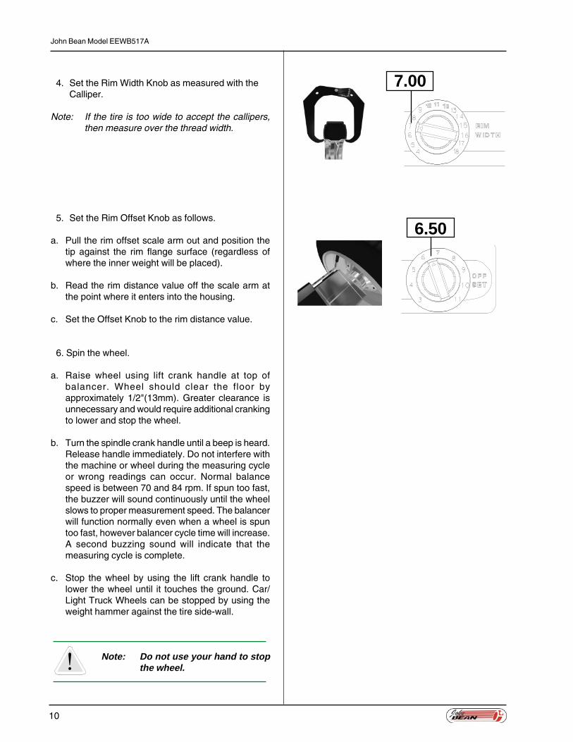
4. Set the Rim Width Knob as measured with theCalliper.
Note: If the tire is too wide to accept the callipers,then measure over the thread width.
5. Set the Rim Offset Knob as follows.
a. Pull the rim offset scale arm out and position thetip against the rim flange surface (regardless ofwhere the inner weight will be placed).
b. Read the rim distance value off the scale arm atthe point where it enters into the housing.
c. Set the Offset Knob to the rim distance value.
6. Spin the wheel.
a. Raise wheel using lift crank handle at top ofbalancer. Wheel should clear the floor byapproximately 1/2"(13mm). Greater clearance isunnecessary and would require additional crankingto lower and stop the wheel.
b. Turn the spindle crank handle until a beep is heard.Release handle immediately. Do not interfere withthe machine or wheel during the measuring cycleor wrong readings can occur. Normal balancespeed is between 70 and 84 rpm. If spun too fast,the buzzer will sound continuously until the wheelslows to proper measurement speed. The balancerwill function normally even when a wheel is spuntoo fast, however balancer cycle time will increase.A second buzzing sound will indicate that themeasuring cycle is complete.
c. Stop the wheel by using the lift crank handle tolower the wheel until it touches the ground. Car/Light Truck Wheels can be stopped by using theweight hammer against the tire side-wall.
Note: Do not use your hand to stopthe wheel.
7.00
6.50

Operation Guide
11
7. Attach the Weight.
a. Starting with either side of the wheel, rotate thewheel in the direction of the lit arrow until all 6Arrow Indicators and the Top Dead-Center Indicatorare lit. The correct balance weight will now bedisplayed.
b. Securely apply the displayed weight at the top-dead-center location on the indicated side of thewheel.
c. Repeat steps 7a and 7b for the other side of thewheel.
8. Do a Check Spin
Repeat the spin cycle (step 6). Zero weight readingsshould appear for both sides of the rim.
Optional: If desired wheels may also be Fine Balancedto 2 gram (Car/Light Truck) or 5 gram (Truck) accuracy.Press the Fine Button on the left side of the ControlPanel. It is necessary to spin the wheel again whenthe Car LED is lit, as the balancer calculates the finebalancing requirements from the previousmeasurements, and the Display will show the weightrequirements. When balancing Truck wheels, it isnecessary to re-spin the wheel after switching to Fine.If a repeatable balance can not be achieved, there is apossibility of foreign material moving around inside ofthe tire causing a different imbalance every time. Thismaterial must first be removed before the wheel canbe balanced.

12
John Bean Model EEWB517A
Balancing Errors.
The crank handle has a one-way clutch for operatorsafety, which also ensures that the wheel is spun inthe correct direction. It is however possible to spin thewheel in the wrong direction (counter clockwise) whenusing the Hub Nut. If this error occurs it will be identifiedby an ‘EEE’ appearing in the Display Window.
If the wheel is intentionally (manually aborted) oraccidentally (wheel touches floor or operator) slowedor stopped during the measuring cycle, ‘EEE’ will alsoappear in the Display Window.
Spinning the wheel in the proper direction up tobalancing speed will remove this error and allow thebalancer to function normally.
In some cases when a very light wheel (i.e. a 13"automobile wheel) is being balanced, ‘EEE’ mayappear. Re-spinning at a higher speed will prevent thisoccurring and allow such wheels to be balanced.
Operation Guide
13
WEIGHT MODES
The EEWB517A balancer features one Normal (clip-on) and four Custom (Alu/Mag) Modes for combinationsof clip-on and stick-on weights. A static balancing modeis also included.
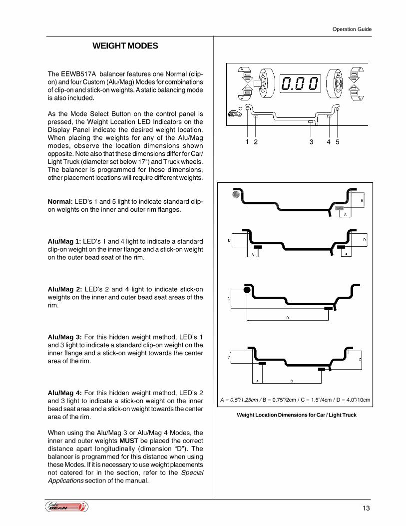
As the Mode Select Button on the control panel ispressed, the Weight Location LED Indicators on theDisplay Panel indicate the desired weight location.When placing the weights for any of the Alu/Magmodes, observe the location dimensions shownopposite. Note also that these dimensions differ for Car/Light Truck (diameter set below 17") and Truck wheels.The balancer is programmed for these dimensions,other placement locations will require different weights.
Normal: LED’s 1 and 5 light to indicate standard clip-on weights on the inner and outer rim flanges.
Alu/Mag 1: LED’s 1 and 4 light to indicate a standardclip-on weight on the inner flange and a stick-on weighton the outer bead seat of the rim.
Alu/Mag 2: LED’s 2 and 4 light to indicate stick-onweights on the inner and outer bead seat areas of therim.
Alu/Mag 3: For this hidden weight method, LED’s 1and 3 light to indicate a standard clip-on weight on theinner flange and a stick-on weight towards the centerarea of the rim.
Alu/Mag 4: For this hidden weight method, LED’s 2and 3 light to indicate a stick-on weight on the innerbead seat area and a stick-on weight towards the centerarea of the rim.
When using the Alu/Mag 3 or Alu/Mag 4 Modes, theinner and outer weights MUST be placed the correctdistance apart longitudinally (dimension “D”). Thebalancer is programmed for this distance when usingthese Modes. If it is necessary to use weight placementsnot catered for in the section, refer to the SpecialApplications section of the manual.
1 2 3 4 5
A = 0.5”/1.25cm / B = 0.75”/2cm / C = 1.5”/4cm / D = 4.0”/10cm
Weight Location Dimensions for Car / Light Truck

14
John Bean Model EEWB517A
Static Balancing: For this method, only LED 3 lightsto indicate a single clip-on or stick-on weight. The weightcan be positioned on the inner or outer rim flange, ortowards the center of the rim. If the imbalance is large,the amount of weight required can be divided equallybetween the inner and outer rim flanges.
For static balancing, the rim width and offset dimensionsdo not need to be entered into the balancer, simplyenter the wheel diameter. After the measuring cycle,the inner arrow LED’s and TDC indicators will light toshow the required weight amount and position.
For simple and accurate balancing, the Normal modecan be used for all balancing measurements. After thebalancing cycle, press the Mode Select Buttonrepeatedly until the LED indicators light for the desiredweight locations. The balancer will automaticallyrecalculate the weight required for each mode.
Weight Location Dimensions for Truck
A = 1.0"/2.5cm / B = 1.5"/4cm / D = 6.0”/15cm

Operation Guide
15
SPECIAL APPLICATIONS
Occasionally it may be necessary to use weightlocations which are different than those catered for inthe standard Alu/Mag programs. This will usually onlyoccur for hidden weight methods, where the distancebetween the weights of 10 cm (4") for car/light truck or15 cm (6") for truck is not suitable. If you encounter anysituation where special weight locations are requiredproceed as follows:
1. Select Normal (clip-on) Mode.
Press the Mode Select Button repeatedly until WeightLocation LED Indicators 1 and 5 are lit.
2. Set the Rim Diameter Knob.
When using stick-on weights set the knob diameter toless than that indicated on the tire sidewall. Typicallyon a 14" rim the diameter would be set to 12.5" and a22.5" rim to 19.5". For thicker rims the diameter mayneed to be set lower.
3. Set the Rim Width Knob.
Measure the distance between the two weight locationsA and B. If weight B is a hidden weight use a tapemeasure or rule. If weight B is on the outer the caliperscan be used. Set the Width Knob as measured.
4. Set the Rim Offset Knob.
Pull the rim offset scale out and position the tip at thepoint where the inner weight is to be located. Set theRim Offset Knob to the distance measured.
O DI D

16
John Bean Model EEWB517A
5. Spin the Wheel.
Complete normal balance routine.
6. Attach the Weight.
Starting with either weight location, rotate the wheeluntil the TDC position is found. Attach the weight asindicated in the Display Panel. N.B. If the weight is notattached at the correct locations (as measured),accurate balance results will not be achieved. Repeatthis step for the other weight location.
7. Do a Check Spin.
Repeat the normal balance routine. Zero weightreadings should appear for both weight locations.

Operation Guide
17
WHEEL MOUNTING
Careful wheel mounting is essential, as the wheel isbalanced relative to how it is mounted on the balancer.If the wheel is not well centered and sitting squarelyagainst the balancer flange plate, accurate balanceresults will not be achieved.
Most stud-centered wheels have concentric center holes,which allow fast and easy cone mounting. Adaptersshould be used only in problem situations and on someaftermarket specialty wheels.
The Standard Accessories and Optional Accessoriessupplied with your EEWB517A balancer allow thefollowing wheels mounting methods.
Wheel Mounting Methods (Truck Wheels)
Cone Mounting
Hub piloted wheels must be cone mounted. Hub pilotedwheels can be identified by the lack of stud holecountersinks.
Install the Spacer Ring / Distance Ring against the backflange of the balancer. The Ring is required for large andmedium truck cones, and is optional for use with lighttruck cone.
Choose a cone that fits best when placed into the wheelcenter hole. With the tire on the ground, slide thebalancer so that the spindle extends through the wheelcenter hole as shown. Mount the cone on the protrudingspindle and slide into the wheel center hole. Raise orlower the spindle with the lift handle as needed foroptimum alignment. Thread the Spindle Nut or Hub Nut,whichever is appropriate, onto the spindle and handtighten. Raise the wheel slightly so that it clears theground and securely tighten the Spindle or Hub Nut.

18
John Bean Model EEWB517A
Combination / Bolt Plate Adapters
Stud piloted wheels must be mounted using thecombination adapter or a bolt plate adapter. Stud pilotedwheels can be identified as those with stud holecountersinks.
For the combination adapter, clean the balancer flangeand attach the adapter flange plate. Select the relevantclamping plate (4 or 5 star), and position the studs onthe correct P.C.D. With the tire on the ground, slide thebalancer so that the spindle extends through the wheelcenter hole. Mount the clamping plate on the protrudingspindle and slide into the wheel stud holes. Raise orlower the spindle with the lift handle as needed foroptimum alignment. Thread the Spindle Nut onto thespindle and hand tighten. Raise the wheel slightly sothat it clears the ground and securely tighten the SpindleNut.
If using a bolt plate adapter, first install spacer ring(P/N 1489) to the balancer flange. Select the correctbolt plate, and facing outwards, slide onto the stub shaft,ensuring that the location pins engage in the relevantholes. Secure the adapter in place by tightening thespindle nut to approximately 50 Nm (184Ibsin-203Ibsin). With the tire on the ground, slide the balancerso that the spindle extends through the wheel centerhole, and the studs align in the stud holes. This mayrequire slight height adjustments using the lift handle.Hand tighten the wheel nuts until snug, then using acrisscross sequence tighten securely to a torque ofapproximately 50Nm (184Ibsin-203Ibsin).

Operation Guide
19
WHEEL MOUNTING METHODS(AUTOMOBILE WHEELS)
Back Cone Mounting
Back cone mounting is the most common way to mountautomobile wheels. Choose the cone that fits bestwhen placed through the wheel center hole from therear. Slide the cone spring and cone on the shaft. Placethe wheel on the cone and be sure that the cone centerthe wheel when you tighten the handle.
The pressure drum should contact the wheel on a flatsurface. Do not center the wheel with the pressure drum.Tighten the wheel firmly against the mounting flange.Hold the handle in place and rotate the wheel whentightening. Be sure that the wheel is firmly against themounting flange and the handle threads engage at leastthree turns on the shaft.
Front Cone Mounting
Front cone mounting is required when using light truckwheels and is also an acceptable alternative for manyautomobile wheels. The wheel center hole must betrue on the outside of the wheel to use the front conemounting method.
Choose the cone that fits best when placed throughthe wheel center hole from the front. Slide the wheel onthe balancer shaft without a back cone or spring on theshaft. Place a cone on the shaft, through the front ofthe wheel. Be sure the cone center the wheel and thatthe wheel is squarely against the mounting flange whenyou tighten the handle.

20
John Bean Model EEWB517A
Back Cone Mounting without PressureDrum
Ensure the handle does not contact the cone, or thewheel will not be centered and mounted securely. Attachthe spacer ring to the hub nut if this situation occurs.
On some extended-center wheels withsmall hub diameters, the pressure drumcannot contact the front face of the wheelproperly. Such wheels can be mountedusing the standard back cone methodwithout a pressure drum. Check that thehandle contacts the wheel center evenlyand that the wheel is centered on the cone.
Double Cone Mounting
The cones must not touch each other. If the conestouch, the wheel will not be centered and mountedsecurely.
Double cone mounting can be used forsome specialty wheels, such as those ona Porsche 928. The back cone centers onthe formed part of the wheel, and the frontcone centers on the hole.
Operation Guide
21
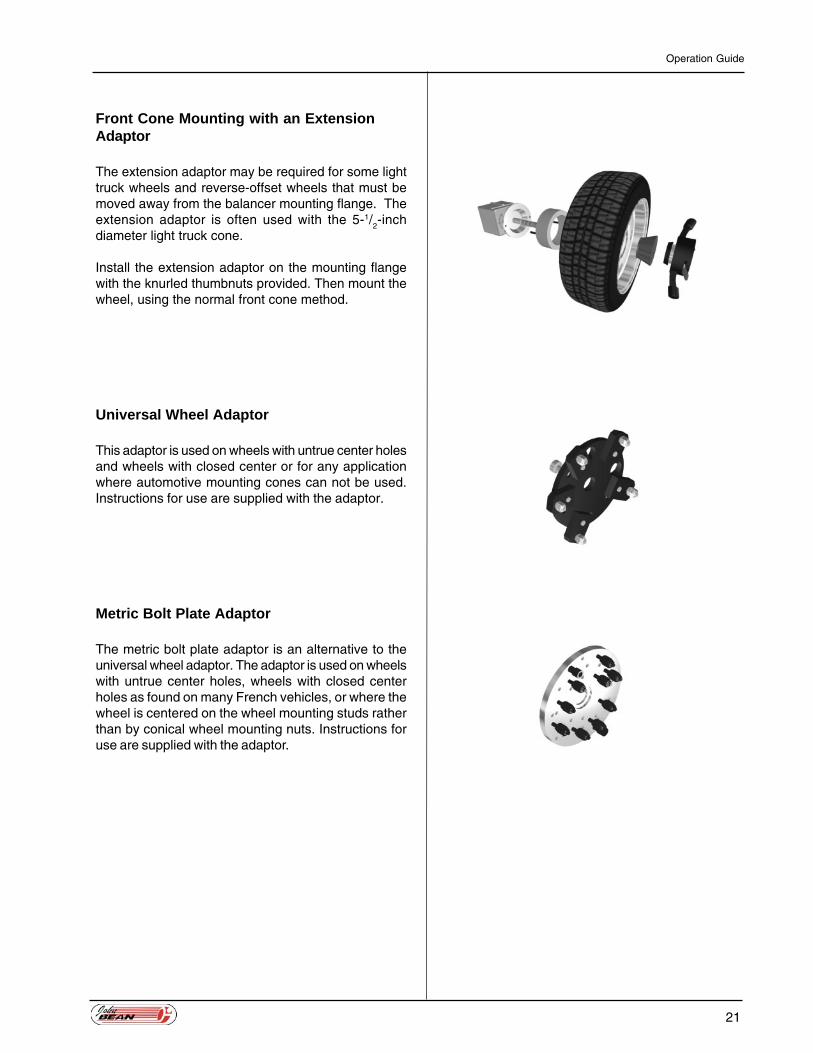
Front Cone Mounting with an ExtensionAdaptor
The extension adaptor may be required for some lighttruck wheels and reverse-offset wheels that must bemoved away from the balancer mounting flange. Theextension adaptor is often used with the 5-1/
2-inch
diameter light truck cone.
Install the extension adaptor on the mounting flangewith the knurled thumbnuts provided. Then mount thewheel, using the normal front cone method.
Universal Wheel Adaptor
This adaptor is used on wheels with untrue center holesand wheels with closed center or for any applicationwhere automotive mounting cones can not be used.Instructions for use are supplied with the adaptor.
Metric Bolt Plate Adaptor
The metric bolt plate adaptor is an alternative to theuniversal wheel adaptor. The adaptor is used on wheelswith untrue center holes, wheels with closed centerholes as found on many French vehicles, or where thewheel is centered on the wheel mounting studs ratherthan by conical wheel mounting nuts. Instructions foruse are supplied with the adaptor.

22
John Bean Model EEWB517A
Wheel Mounting Errors
Regardless of the mounting method used, the wheelmust be centered before balancing. A wheel should bemounted on the appropriate cone or adaptor andtightened carefully to ensure proper centering and matingagainst the balancer flange.
The wheel must be clean and free of large burrs ornicks, especially where it mates with the cone oradaptor and the balancer flange. Any dirt between theflange and the mating surface of the wheel will causemisalignment on the shaft. A misalignment of thethickness of a matchbook cover will cause anunbalance of 15 grams (0.50 ounce) or more onautomobile wheels and 30 grams (1 ounce) on lighttruck wheels.
The wheel must also be tightened securely to preventit from slipping in relation to the flange. If the wheelslips on the balancer, accurate weight measurementand location are impossible.
Wheel Rotational Errors
When a wheel is mounted on the balancer, whetherusing a cone or an adaptor, it is fixed in a particularposition in relation to the balancer shaft. If the wheel isrotated 180 degrees from the initial position andretightening, a different balance reading may result. Suchdifferences are called rotational errors.
When checking balance with the wheel in one positionand then rotating it 180 degrees and re-spinning it, thedifference between the two readings could be as muchas 15 grams (0.50 ounce) for cone-mounted automobilewheels, and 60 grams (2 ounces) for light truck wheels.
The actual balance error is one-half of the displayedamount because the reading is the sum of the errorand the weight required to counterbalance the error.To do a rotational test, first fine-balance the wheel.Then loosen the wheel on the shaft, rotate it 180degrees, and retighten the handle. Spin the wheel inthe normal mode to check for rotational errors.

Operation Guide
23
POWER SOURCES
The balancer may be powered in three different ways.
1. Power Converter/Charger.
The normal power method is to use the power convertersupplied with the equipment. This converter furnishes8.5 VAC ,with sufficient power to operate the equipmentand charge the battery.
2. Battery.
The balancer is equipped with an 8 volt, 8.5 Ampere-Hour lead-acid, maintenance free, gel-cell battery (2each Technacell 4 volt, 8.5 Amp-hour, Model EP485or equivalent) to allow operation when normal poweris not available. The normal power converter shouldbe used to keep the battery charged whenever thebalancer is not in operation. There is no need to unplugthe converter since the battery can not be overcharged.It requires a minimum of 12 hours to fully charge thebattery.
In cases where the battery is allowed to become fullydischarged, the balancer will still operate normally fromthe power converter or an external 12 volt battery.
If the balancer is not used for approximately 10 minutes,the computer puts the equipment into a standby mode.This reduces the power consumption to less than onewatt, except for the power required to charge thebattery. If the balancer is being operated from thebattery, the standby mode will continue to dischargethe battery but at a very reduced rate.
Battery life can be expected to be approximately 5years. Life can be extended by maintaining a full chargeand avoiding excessive vibration and temperaturevariations. If the battery is replaced, care must be takento reconnect with the correct polarity. If the polarity isreversed the 3 Amp fuse (type 3AG/AGC or equivalent)located in the battery compartment will blow. Should itbe necessary to replace the fuse, DO NOT use a slow-blow type or any other rated battery.
Note: Black lead connects to the (-) terminal; Redlead with fuse connects to the (+) terminal.
3. 12v Battery Operation.
The balancer may be powered by any 12 volt battery.Connection is made to the same input connector asthe normal power converter. In this case either polaritymay be used, as the computer can operate from eithera +12 volt or -12 volt DC source.

24
John Bean Model EEWB517A
AUTOMATIC CALIBRATION
The EEWB517A Truck Wheel Balancer is calibratedby computer before shipment and should not requirerecalibration in normal service. If the P.C.B. assemblyor the back panel assembly is replaced, the balancershould be recalibrated. Additionally, if balancing resultsappear to be irregular, the balancer may requirerecalibration. The balancer contains a program forautomatic self-calibration, which can be performed inabout the same time that it takes to balance a singlewheel.
Calibration Procedure
Follow this procedure to calibrate your balancer:
1. Fine balance a Wheel.
Balance a wheel in Fine resolution as explained in theBalancing Operation section. Use a wheel of the kindand size normally balanced on the balancer. The wheelmust be balanced in the NORMAL (clip-on) mode. Ifthe balancer is in the STATIC mode or any of the ALU/MAG modes, the calibration program will not operate.
Accurately set the knobs to the dimensions of the wheel.
2. Attaching Calibration Weight.
Rotate the wheel until both outer position arrows andthe top-dead-center indicator light. Attach the Weightindicated below to the outer wheel rim at TDC.
� Car/Light Truck 100grams (3.00 ounces)(Diameter set at or below 17")
� Truck 400grams (12ounces)(Diameter set above 17")
3. Enter the Calibration Program.
Press and hold the Fine button. While holding the Finebutton down, press and hold the Mode Select Buttonfor 3 to 4 seconds. When the balancer enters thecalibration program, the display will show a flashing‘ccc’.

Operation Guide
25
4. Spin the Wheel at Least Four Times.
Spin the wheel up to the normal balancing speed.After the measuring cycle, a beep will sound and theflashing ‘ccc’ message will reappear on the display.Brake the wheel and re-spin again. Calibration usuallyrequires four consecutive, accurate spins.
After the final accurate spin, the calibration weight willappear on the display for the outer rim flange, and zerowill appear for the inner flange at TDC. Calibration isnow complete.
5. Remove the Calibration Weight.
After successful calibration, the balancer stores the newcalibration values in memory. Remove the calibrationweight from the wheel and proceed with normaloperation of your balancer.
If calibration is abandoned before completion, theoriginal (previous) calibration values are retained.
Calibration Error
If an error occurs during any of the spin cycles, the‘EEE’ error message appears on the display. Thecalibration program is aborted, and the balancer retainsthe previous calibration values.
The ‘EEE’ error message may result from using anincorrect calibration weight. Accidentally bumping thebalancer during calibration also could cause an errormessage. To correct a calibration error, remove thecalibration weight and spin the wheel to remove the‘EEE’. Then verify that the wheel is still Fine balancedand repeat the calibration procedure.
If calibration fails, try the calibration program again fromthe beginning. Changing the wheel and the calibrationweight may correct a calibration failure. If the balancerrepeatedly fails the calibration program, contact yourdistributer for assistance.

26
John Bean Model EEWB517A
SERVICE AND MAINTENANCE
The Truck Wheel Balancer can be maintained with afew simple actions performed at regular intervals.
Wheel mounting accessories and the mountingsurfaces of the flange and shaft of the balancer needto be cleaned regularly. Grease and oil will accumulatedirt which can cause incorrect balancing readings, andcan also act as a grinding compound resulting inpremature wear.
Old wheel weights and other material must be removedfrom under the balancer.
Ensure that tires, rims, tools or other parts are not leftleaning against the balancer body.
Clean the display and input panels with a dry cloth.
If the balancer gets physically damaged or broken,Contact your EEWB517A distributor.
Operational Check
1. Connect the power cord. Switch on the balancer.Press Mode several times. The Weight Modeindicators should light corresponding to eachweight mode selected. Return to the Normal weightmode. Press Fine to set Fine Mode. The Fineindicator should light.
2. Mount a wheel on the balancer and program thewheel dimensions (diameter, width, offset),ensuring that the numeric display shows the valueswhen the dials are moved.
3. Hand-spin the wheel up to speed.

Operation Guide
27
4. Wait for the measuring cycle to complete (10-20seconds). The inner and outer weights should bedisplayed when the wheel is rotated to therespective TDC positions.
5. Fine-balance the wheel to zero.
Attach a 100-gram (3-ounce) weight to the outerrim at the 12 o’clock position when the outer TDCindicator is lit. Spin the wheel and note thereadings. Repeat with the weight moved to the lightspot on the inner rim. The balancer is withincalibration limits if the display shows 90 - 110grams (2.75 - 3.25 ounces) for the side with theweight attached and shows 0 - 10 grams (0 - 0.25ounces) for the side without the weight. If thereadings are not within these limits, verify that thewheel dimensions are set correctly and performthe CALIBRATION procedure, before proceedingto the next step.
6. Remove the 100-gram (3-ounce) weight and verifythat the wheel is balanced in Fine Mode.
7. Rotate the wheel 180o in relation to the mountingflange and re-spin. The sum of the inner and outerreadings should be a maximum of 15 grams (0.50ounces) for a 14" or smaller wheel. If the sum ishigher, make sure the wheel is properly centeredwhen tightening the hub nut. Clean the mountingsurface, spindle, cones and wheel, and then repeatthe check. If the new sum is also too high, repeatthe check with a new wheel.
If the balancer fails any of the abovesteps, contact your service representativefor assistance in correcting the problem.

28
John Bean Model EEWB517A
TROUBLESHOOTING GUIDE
The following tips will help to identify and correct problemswhich may be encountered when using the Truck wheelbalancer.
A. No indicators on the display panel are lit.
There may be no power supplied to the balanceror a cable may be loose.
� Ensure the power converter lead is insertedproperly into the power input connector at therear of the machine.
� Unplug the power converter. Remove the weightpockets and check all cable connections.
B. Display appears to freeze or lock up.
The power to the balancer may have beeninterrupted.
� Remove the battery and remove the power
C. Balancing results are inconsistent.
The balancer may not be resting on a solid andlevel surface, the mounting accessories or stubshaft may be worn or damaged, or the electronicsassembly or sensors may have been replaced.
� Ensure that the balancer is fixed in position.
� Inspect the mounting accessories and stubshaft; replace if necessary.
� Perform the Calibration procedure.
� Move the balancer to a new location and tryagain (note that the balancer is heavy - do notmove the balancer without assistance).

Operation Guide
29
F. Spinning wheel by hand - ‘EEE’ is reported.
The wheel may have been spun in the wrong direction(anti-clockwise when facing the outer rim), or the wheelhas been spun up to measuring speed (the balancerbeeps once) and then slowed, or stopped, before thebalancing cycle is completed.
� Re-spin the wheel, spinning it in the correctdirection (clockwise when facing the outer rim).
� Ensure that the wheel is mounted properly andthat the Hub Nut is securely tightening the wheelagainst the flange; the wheel must not slip onthe shaft.
� Check that wheel movement is not beingimpeded.
� When only a wheel rim is mounted, the rim maybe too light to maintain speed; try spinning therim a little faster.
G. Balancer beeps continuously.
The wheel has been spun too fast by hand and isspinning above the measurement speed range, orthere may be a fault in the electronics assembly.
� Wait until the wheel slows to a speed within therequired range or carefully slow the wheel. Thebalancer will no longer beep when the wheelspins at the correct measuring speed, and willcontinue with the balancing cycle.
� If the balancer continues to beep even whenthe wheel is slowed or stopped, then thebalancer should be switched off. Wait a fewseconds and then turn on the power again.
H. The decimal point is constantly displayed.
The balancer is set to display weight units in ounces,or the display electronics are faulty.
� To change weight units, press Hidden button andthen press Fine on the input panel. Hold bothpressed for 3 seconds. The balancer will beepand the decimal point will be turned off.
� If this does not work, the electronics assemblyshould be replaced.
30
John Bean Model EEWB517A
TECHNICAL SPECIFICATIONS
Rim diameter range: 330-660mm (13-26")
Rim width range: 101-457mm (4-18")
Rim offset range: 76-297mm (3-11")
Maximum wheel diameter: 1300mm (50.5")
Maximum wheel weight: 227kg (500lbs)
Using standard mounting accessories. The EEWB517Ais additionally capable of handling wheel weights of500lbs (227Kg) using special mounting techniques atvery large offsets. (ie. wheel and brake drumassemblies).
Power requirements:
Operates from 100/110/220/240 volt 50/60 Hz mainssupply depending on power converter supplied or fromits own built in rechargeable battery. Optional cable toconnect to any 12 volt car battery.
Balancer weight: 104kg (229lbs)
Balancer dimensions:
� Height (H) 1145mm (45").� Floor area (L x W) 980x915mm.
(42"x36").
Shipping weight: (B920) 176kg (387lbs)
Shipping dimensions:
� (L x W x H) (B920) 110"x100"x125"
Balancing modes:
� Truck: Normal (clip-on), 4 Alu/Mag, and static.� Automobile: Normal (clip-on), 4 Alu/Mag, and
static.
Operation Guide
31
Balancing accuracy:
� Standard resolution: 25 grams (1 ounce) fortruck wheels - 5 grams (0.25 ounce) forautomobile wheels.
� Fine resolution: 5 grams (0.25 ounce) for truckwheels - 2 grams (0.10 ounce) for automobilewheels.
Balancing cycle: 8 to 20 seconds dependingon wheel size.
Calibration: Automatic self calibrating.
The information and specifications in thismanual are based on the latest informationavailable at the time of publication. The productmanufacturer reserves the right to change thespecifications at any time without notice.

32
John Bean Model EEWB517A
This product is protected under the following Patents,and Patent Applications Pending:
U.S.A. 4,435,9824,489,6084,507,9644,741,2115,189,9125,419,193
U.K. GB 2 131 561 BGB 2 153 095 B
Canada 1,217,6611,230,758
France 2 536 8572 558 591
Japan 73374006-06597507-015423
Australia 574053575371625,780661,552
Europe 0,358,496 (DE P689 21 271.2-08,GB, FR, ES, IT, NL)
Germany DE 35 01 577 C2
Ireland S 58405
Italy 1,182,123


Notice: The information contained in this document is subject to change without notice. John Beanmakes no warranty with regard to this material. John Bean shall not be liable for errors contained hereinor for incidental consequential damages in connection with furnishings, performance, or use of thismaterial.
This document contains proprietary information which is protected by copyright and patents. All rights arereserved. No part of this document may be photocopied, reproduced, or translated without prior writtenconsent of John Bean.
is a registered trademark of John Bean and Snap-on Equipment
ZEEWB517A... 58xx...03/03/2003...wdc...copyright 2003 Snap-on Equipment Printed in the USA
USAJohn Bean309 Exchange AvenueConway, Arkansas 72032Tel.: (800) 362-8326 or (501) 450-1500Fax: (501) 450-1585
FRANCEJohn BeanSnap-On Equipment FranceZ.A. Du Vert Galant15, rue de la GuivernoneBP 717595310 Saint Ouen L’AumoneTel: (33) 1-3448-5878Fax: (33) 1-3448-5879
UNITED KINGDOMSnap-On Equipment Ltd.John Bean Equipment GroupOldmedow RoadKings LynnNorfolkPE30 4JW
CANADAJohn Bean6500 Millcreek DriveMississauga, OntarioCanada L5N 2W6Tel: (905) 814-0114Fax: (905) 814-0110
JBC GERMANYGeschaeftsbereich der Snap-on Equipment GmbHWerner-von-Siemens-Str. 2D-63419 PfungstadtDeutschlandTel: +49 (0) 6157 12 600Fax: +49 (0) 6157 12 601Website: www.johnbean.de
LATIN AMERICASnap-on Tools International, Ltd.2801 80th StreetKenosha, WI 53143Tel: (262) 656-5003Fax: (414) 656-1403