Troubleshooting and lessons learned using protective relay ... · Troubleshooting and Lessons...
117
1 Troubleshooting and Lessons Learned Using Protective Relay Event Analysis GE Digital Energy Multilin
Transcript of Troubleshooting and lessons learned using protective relay ... · Troubleshooting and Lessons...
11
Troubleshooting and Lessons Learned Using Protective Relay Event Analysis
GE Digital Energy Multilin

33
Seminar Agenda
• Overhead distribution ground fault inside industrial facility causes a generator stator fault
• Incorrect current transformer wiring causes bus fault during power transformer energization
• Fault on distribution system causes unusual transformer high side currents• Incorrect current transformer wiring causes motor thermal overload trip• Generator loss of excitation and reverse power trips• Overcurrent trip on paralleling switchgear• Synchronous motor trip on power factor• Substation heat pumps drops bus voltage by 1kV causes capacitor bank
trip

44
Review Of Symmetrical Components
55
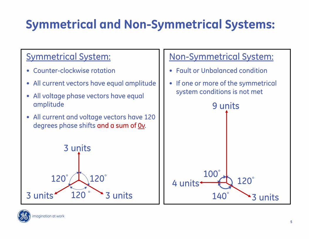
Symmetrical and Non-Symmetrical Systems:
Symmetrical System:• Counter-clockwise rotation
• All current vectors have equal amplitude
• All voltage phase vectors have equal amplitude
• All current and voltage vectors have 120 degrees phase shifts and a sum of 0v.
3 units
3 units
3 units
120°120°
120 °
Non-Symmetrical System:• Fault or Unbalanced condition
• If one or more of the symmetrical system conditions is not met
3 units
9 units
4 units 120°100°
140°

66
• A-B-C Counter-clockwisephase rotation
• All phasors with equal magnitude
• All phasors displaced 120 degrees apart
• No Rotation Sequence
• All phasors with equal magnitude
• All phasors are in phase
• A-C-B counter-clockwisephase rotation
• All phasors with equal magnitude
• All phasors displaced 120 degrees apart
Positive Sequence (Always Present)
C
A
B
Zero Sequence Negative Sequence
C
A
B
ABC
120
120
120120
120
120
Symmetrical Components:

77
Symmetrical Components:
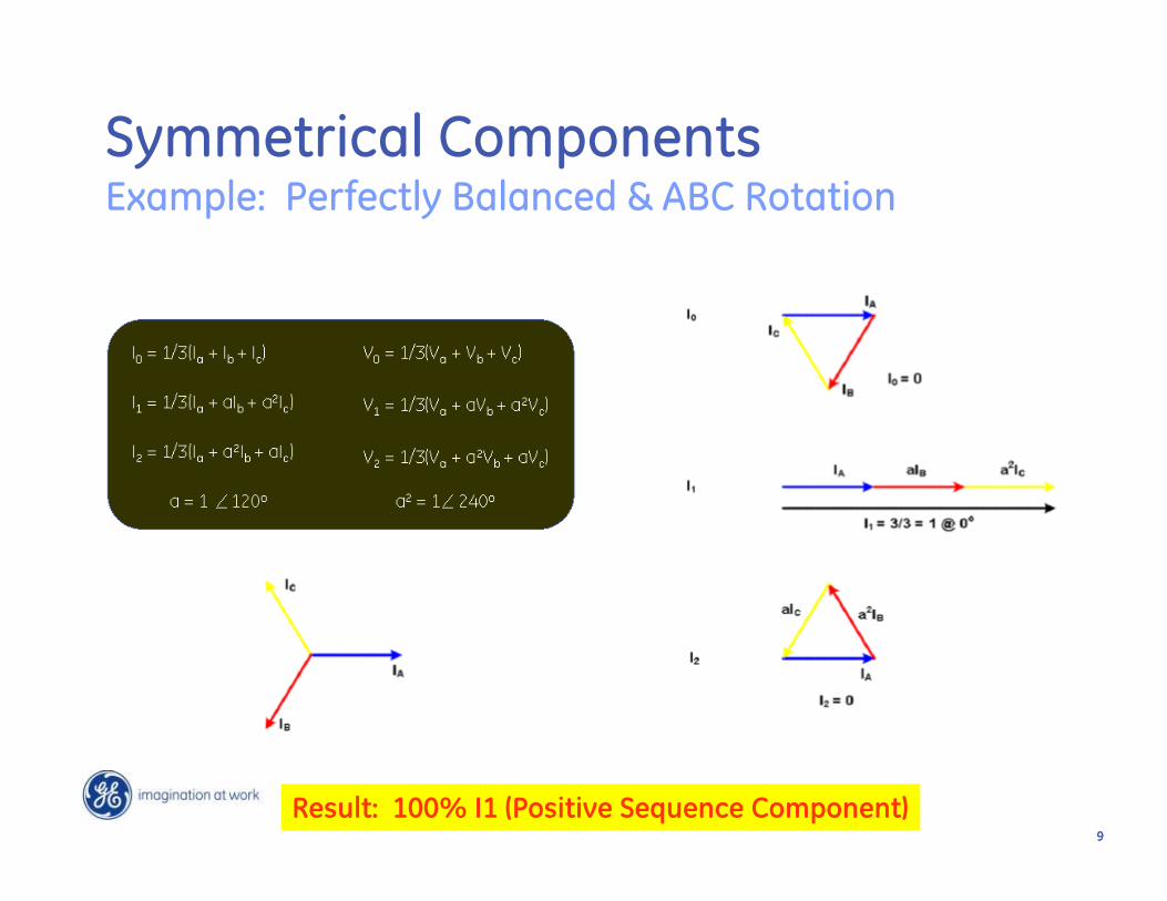
I0 = ⅓ (Ia + Ib + Ic)
I1 = ⅓ (Ia + Ib + 2Ic)
I2 = ⅓ (Ia + 2Ib + Ic)
V0 = ⅓ (Va + Vb + Vc)
V1 = ⅓ (Va + Vb + 2Vc)
V2 = ⅓ (Va + 2Vb + Vc)
Unbalanced Line-to-Neutral Phasors:
ABC
Zero Sequence Component:
PositiveSequence Component:
NegativeSequence Component:
2 = 240
CA
B = 120
Ia = I1 + I2 + I0
Ib = 2I1 + I2 + I0
Ic = I1 + 2I2 + I0
Va = V1 + V2 + V0
Vb = 2V1 + V2 + V0
Vc = V1 + 2V2 + V0
=Phasor @ +120
2 =Phasor @ 240

88
Calculating Symmetrical Components:
Three-Phase Balanced / Symmetrical System
*Vc
Va
2* Vb
3V2 =0
VcVa
Vb
3V0 =0
2*VcVa * Vb
3V1
Open-Phase Unbalanced / Non-Symmetrical System
Vc
Va
Vb
Ic
IaIb 2*Ic
Ia* Ib
3I1
*Ic
Ia
2* Ib
3I2 Ic
Ia
Ib3I0
Positive Negative Zero
Positive Negative Zero
Vc
Va
Vb
Ic
IaIb
99
Symmetrical ComponentsExample: Perfectly Balanced & ABC Rotation
Result: 100% I1 (Positive Sequence Component)

1010
I2
Symmetrical ComponentsExample: B-Phase Rolled & ABC Rotation
Result: 33% I1, 66% I0 and 66% I2

1111
Symmetrical ComponentsExample: B-Phase & C-Phase Rolled & ABC Rotation
Result: 100% I2 (Negative Sequence Component)

1212
Summary of Symmetrical Components:
• Under a no-fault condition, the power system is considered to be essentially symmetricaltherefore, only positive sequence currents and voltages exist.
• At the time of a fault, positive, negative and possibly zero sequence currents and voltages exist.
o All positive, negative and zero sequence currents can be calculated using real world phase voltages and currents along with Fortescue’s formulas.
o In = Ia + Ib + Ic = 3 I0

1313
Data Sample 1 = No Fault Data Sample 2 = Fault
Relay
Power System FaultsFault Analysis

1414
300 A
300 A
300 A
120°
120°
120°
For Normal Conditions:
Data Sample 1 = No Fault
Data Sample 1 Phasor Diagram:
Waveform Capture:
Power System FaultsFault Analysis

1515
Negative Sequence Component, I2:For Fault Condition:
I2 = 200 A
2Ib = 300 A
Ic = 300 A
I2= 1/3(600 A)Ia = 900 A
I2 = 1/3(Ia+2Ib+Ic)
= 1/3(600 A)
I2 = 200 Amps
600 A
Power System FaultsFault Analysis - Example

1616
Zero Sequence Component, I0:For Fault Condition:
300 A
900 A
300 A
Ib Ic
I0= 1/3(Ia+Ib+Ic)
Power System FaultsFault Analysis - Example
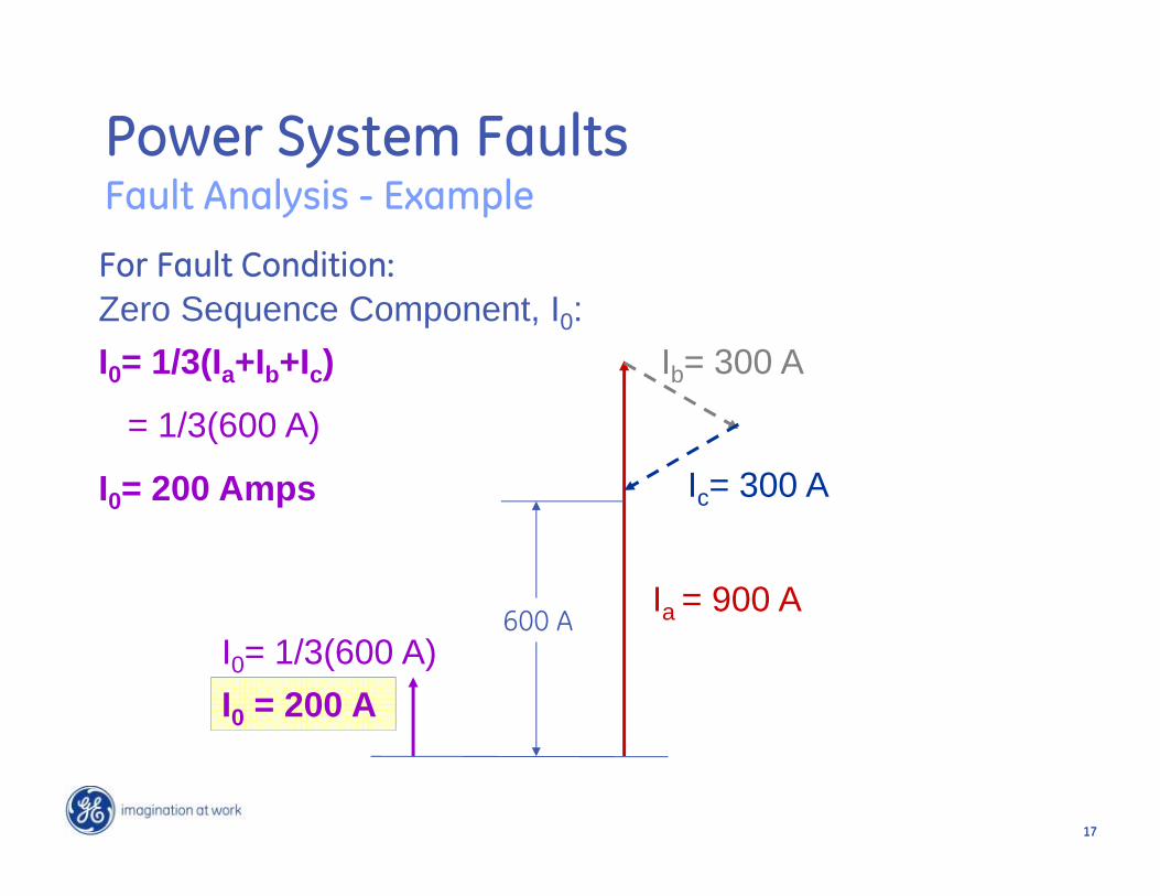
1717
Zero Sequence Component, I0:For Fault Condition:
Ib= 300 A
Ic= 300 A
Ia = 900 A
I0= 1/3(Ia+Ib+Ic)
= 1/3(600 A)
I0= 200 Amps
I0 = 200 AI0= 1/3(600 A)
600 A
Power System FaultsFault Analysis - Example

1818
Verifying Fault Current on Phase A:For Fault Condition:
Ia = I1 + I2 + I0= 500 A + 200 A + 200 A
Ia = 900 Amps= actual fault current measured on Phase A
Fault, Ia
At the time of a fault, positive (I1), negative (I2) and possibly zero (I0) sequence currents exist.
Power System FaultsFault Analysis - Example

1919
Sequence Networks
• Where is sequence voltage highest?
• What generates negative and zero sequence currents?

2020
How do we connect so that I1=I2=I0?
• The sequence networks have to be in series for a phase to ground fault on a solidly grounded system.
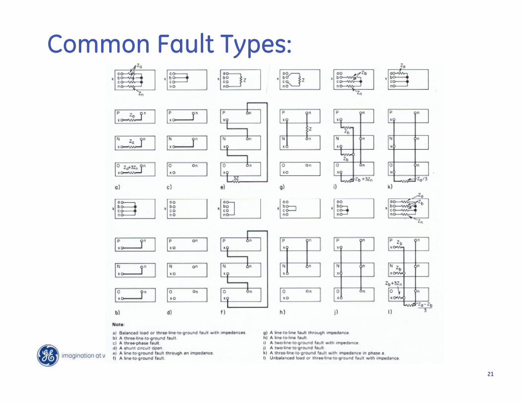
2121
Common Fault Types:

2222
Transformer Interconnections:

2323
Analysis of Interesting Events Using Waveforms

24
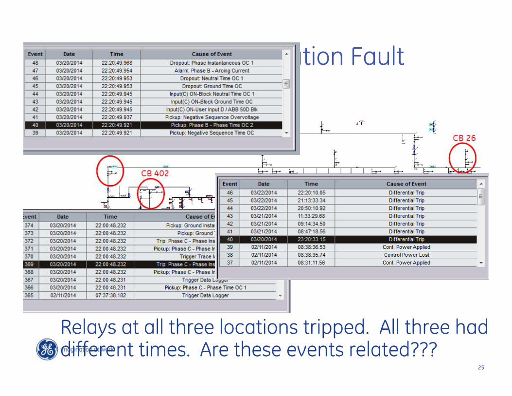
Snake Causes a Distribution Fault
25
Snake Causes a Distribution Fault
Relays at all three locations tripped. All three had different times. Are these events related???
26
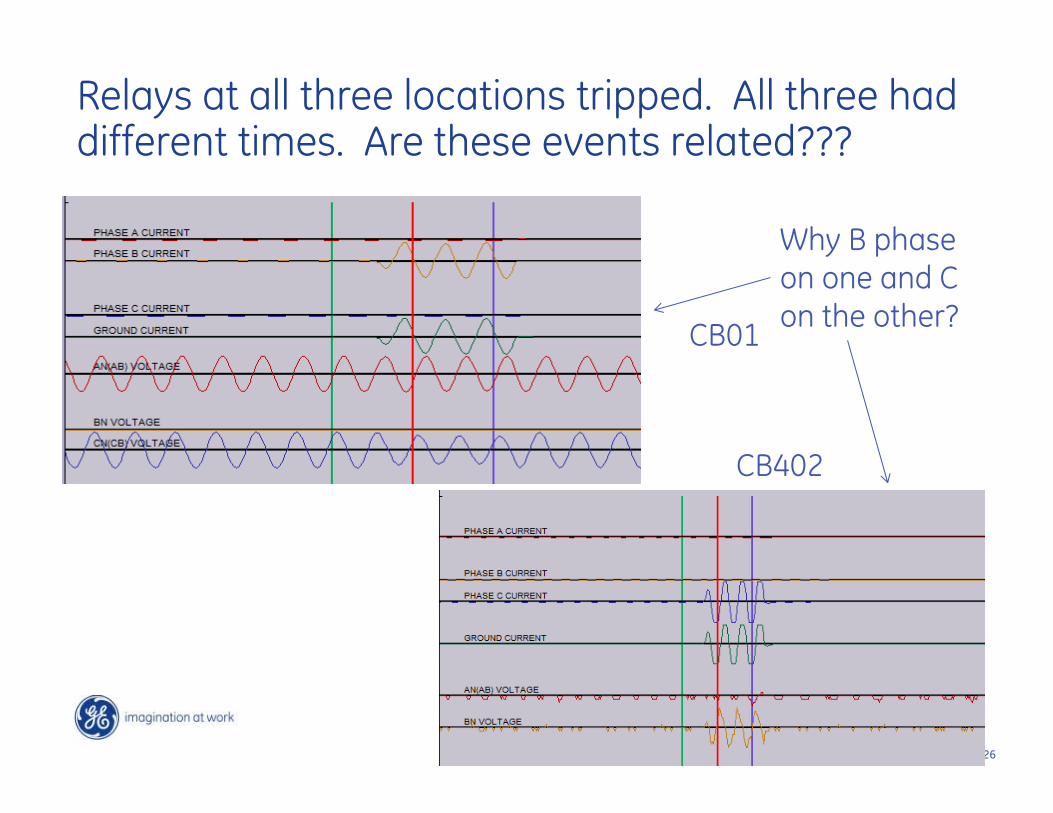
Relays at all three locations tripped. All three had different times. Are these events related???
CB01
CB402
Why B phase on one and C on the other?

27
What about the Generator???
C phase terminal fault current, but…
Small C phase neutral fault current
CG Stator fault close to the terminal

28
What happened here??
• C phase to ground fault because of the snake• Zone interlocking scheme failed because of a
settings error• Generator failed due to the extra stress
caused by the fault.• Biggest Challenge was synchronizing the
time differences in the relays.

29
Challenges to Time Synch
30
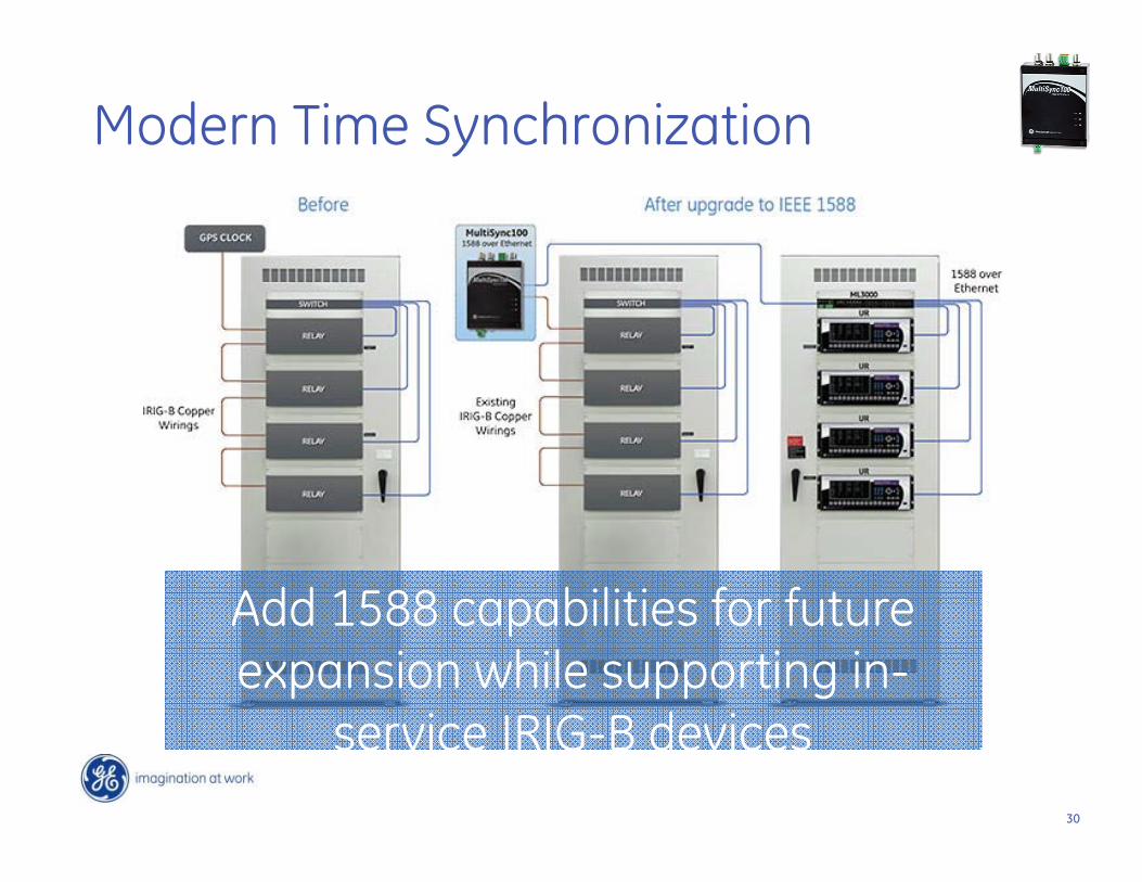
Modern Time Synchronization
Add 1588 capabilities for future expansion while supporting in-
service IRIG-B devices

31
1588 Protocol over a wide area with legacy devices
32
Generator Relay Failure to Trip on Loss of Excitation

3333
The Story
• We lost the exciter• The relay failed to trip on loss of excitaton

34
This ring down in current looks like loss of excitation (40)
But 40 function does not operate!
35
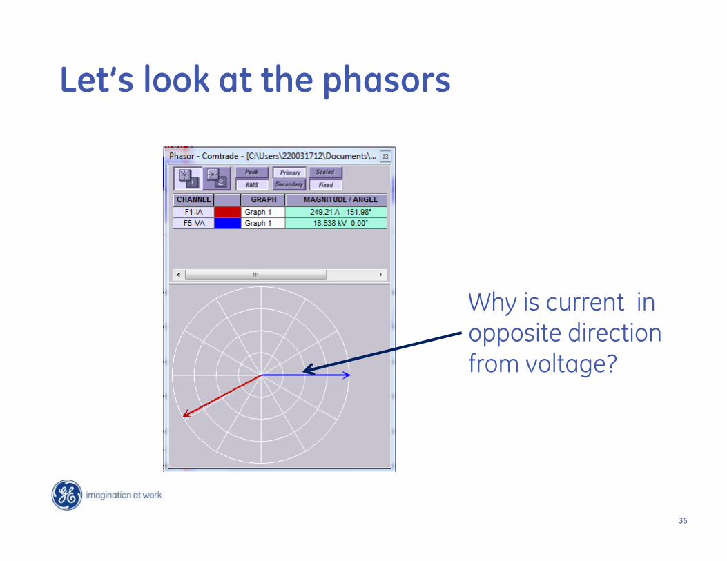
Why is current in opposite direction from voltage?
Let’s look at the phasors
36
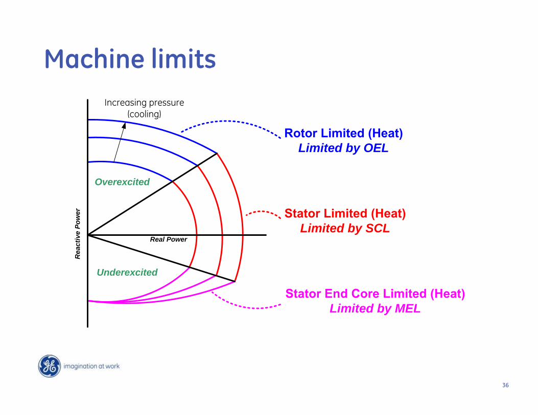
Limited by OEL
Limited by SCL
Limited by MEL
Overexcited
Underexcited
Real Power
Rea
ctiv
e Po
wer
Increasing pressure (cooling)
Machine limits
37
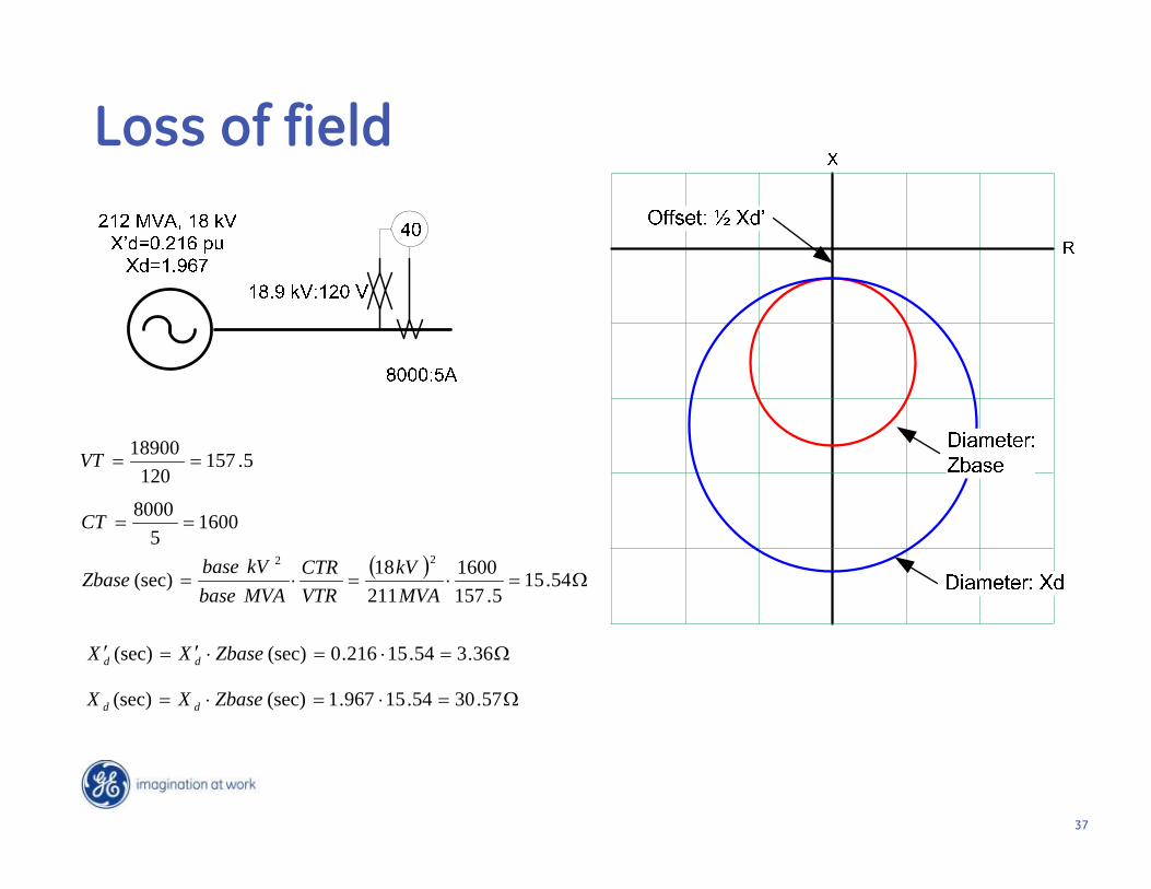
Loss of field
5.157120
18900VT
16005
8000CT
54.15
5.1571600
21118(sec)
22
MVAkV
VTRCTR
MVAbasekVbase
Zbase
36.354.15216.0(sec)(sec) ZbaseXX dd
57.3054.15967.1(sec)(sec) ZbaseXX dd

38
Something with your current is not right !
Ok, then why don’t I trip on Differential?

39
Once I account for transformer, currents sum to zero

40
So what's wrong with 40 function?

4141
Fault on Distribution System Causes
Unusual Transformer High Side Currents
4242
The Story
• Distribution transformer feeding medium voltage overhead distribution.
• In oscillography, we see two phases of fault current on the high side of the transformer for a single phase to ground fault on the low side
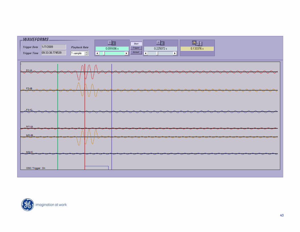
4343
4444
4545

4646
F1 Symmetrical components
M1 Symmetrical components
Pre-fault all positive seq.
Pre-Fault Values
4747
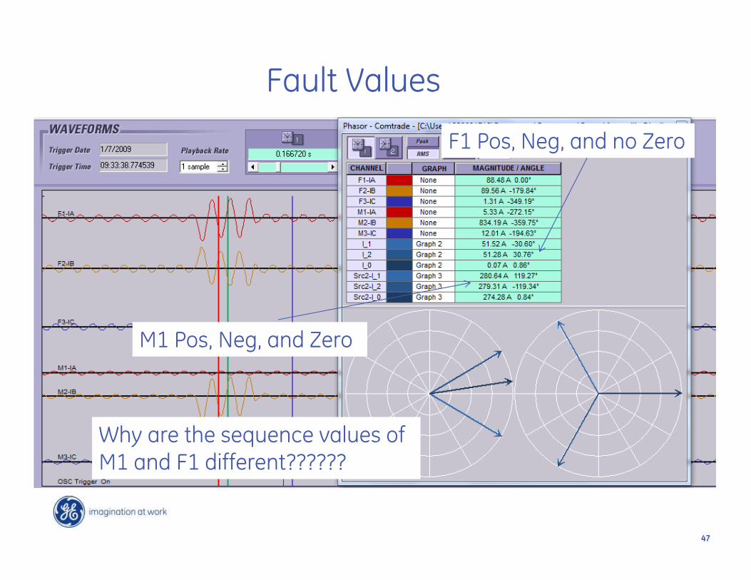
Fault Values
F1 Pos, Neg, and no Zero
M1 Pos, Neg, and Zero
Why are the sequence values of M1 and F1 different??????

4848
The Fault Network as Seen From F1

4949
The Fault Network as Seen From M1

5050
What Effect Does this Fault Have on Voltage?

5151
What Effect Does this Fault Have on Voltage?

5252
Incorrect current transformer wiring causes
bus fault during power transformer energization

5353
The Story
• I have energized the transformer• As soon as I pickup load, I get a
transformer differential.

54
Oscillography
Percent Differential Operates

55
Oscillography

56
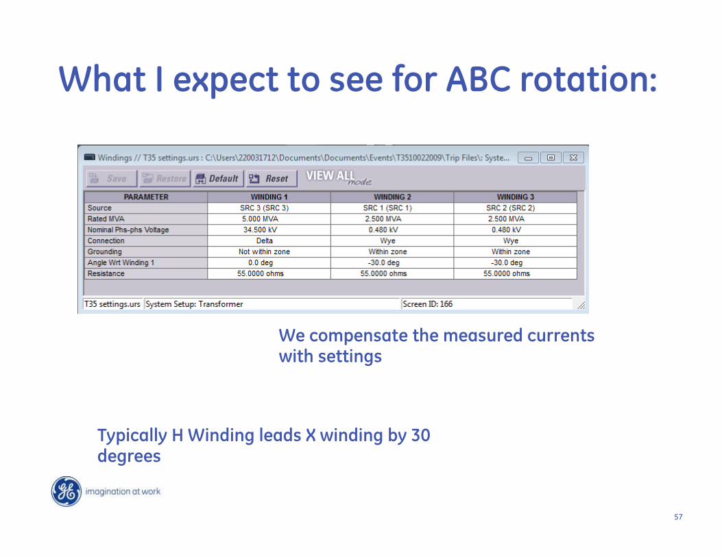
What I expect to see for ABC rotation:
Typically H Winding leads X winding by 30 degrees
57
What I expect to see for ABC rotation:
Typically H Winding leads X winding by 30 degrees
We compensate the measured currents with settings

58
What I expect to see for ABC rotation:

59
But this isn’t ABC rotation:

60
But this isn’t ABC rotation:
Typically H Winding lags X winding by 30 degrees on ACB rotation

61
Trip occurred because of setting
Typically H Winding lags X winding by 30 degrees on ACB rotation

62
What happens if I swap phases on my H winding:
Swapping phases on the High side changes my transformer from 30 lag to 30 lead
c
a
C
A

63
Reversed Phase Causes Motor Thermal Overload Trip

6464
The Story
• New switchgear feeding motor• When we start the motor, it trips after
about 10 minutes.

6565
Waveforms
Clearly, there is a phase reversed
Why would this take 10 minutes to trip

6666
• Thermal Capacity Used (TCU) is a criterion selected in thermal model to evaluate thermal condition of the motor.
• TCU is defined as percentage of motor thermal limit utilized during motor operation.
• A running motor will have some level of thermal capacity used due to Motor Losses.
• Thermal Trip when Thermal Capacity Used equals 100%
Thermal Model – Thermal Capacity Used

6767
Thermal Model - Current Unbalance BiasNegative sequence currents (or unbalanced phase currents) will cause additional rotor heating that will be accounted for in Thermal Model.
Positive Sequence
Negative Sequence
• Main causes of current unbalance• Blown fuses• Loose connections• Stator turn-to-turn faults• System voltage distortion and unbalance• Faults

6868
Thermal Model - Current Unbalance Bias
• Equivalent heating motor current is employed to bias thermal model in response to current unbalance.
))II(K(1II 212
2MEQ
• Im - real motor current; K - unbalance bias factor; I1 & I2 - positive and negative sequence components of motor current.
• K factor reflects the degree of extra heating caused by the negative sequence component of the motor current.
• IEEE guidelines for typical and conservative estimates of K.
2LRCI175K TYPICAL
2LRCI230K CONSERVATIVE
6969
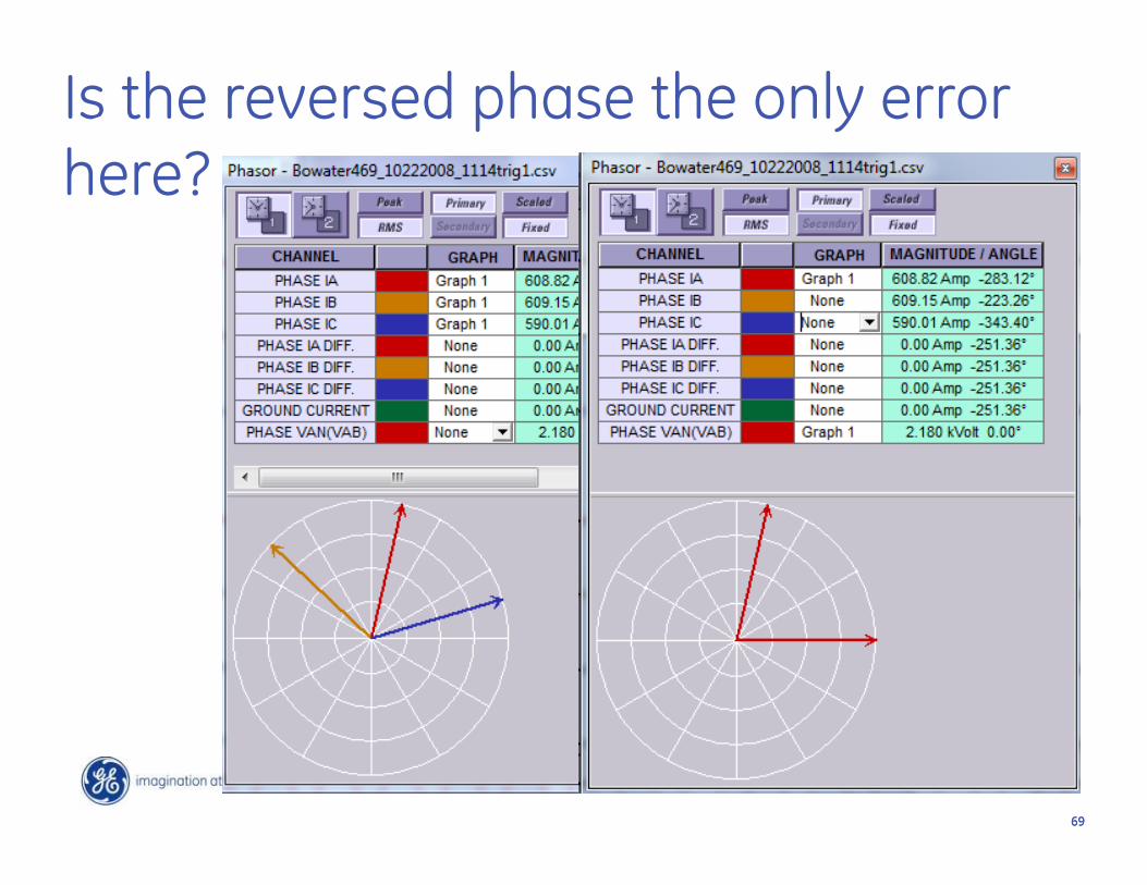
Is the reversed phase the only error here?

7070
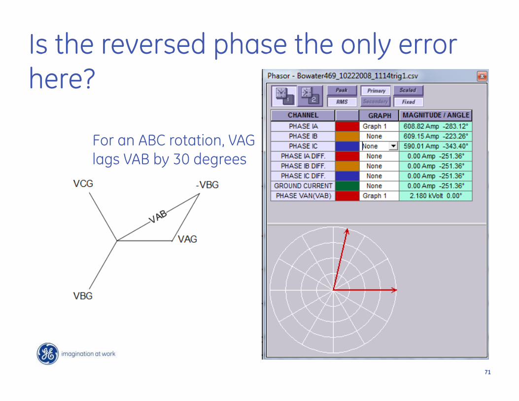
VAB voltage relative to VAG
For an ABC rotation, VAG lags VAB by 30 degrees
7171
Is the reversed phase the only error here?
For an ABC rotation, VAG lags VAB by 30 degrees

7272
How to fix
For an ABC rotation, VAG lags VAB by 30 degrees
What is really A phase is wired to B phase and is rolled 180 degrees

7373
How to fix
Move wire from B to A and roll 180 degrees
Move wire from C to B and roll 180 degrees
Move wire from A to C and don’t roll.
7474
Lessons Learned
• This relay had a rolled phase, but also a lot of other issues
• During start up, verify metered values• Negative sequence voltage and current should be
small relative to positive sequence quantities• Power factor should be as expected 80-90% lagging
for induction machines and loads.• Phase relationships should be as expected (across
transformers)

75
Low Impedance Bus Differential Trip When the Second Breaker is Closed
on the Bus

7676
The Story
• We are installing a bus differential• When we pick up load, we trip

77
78
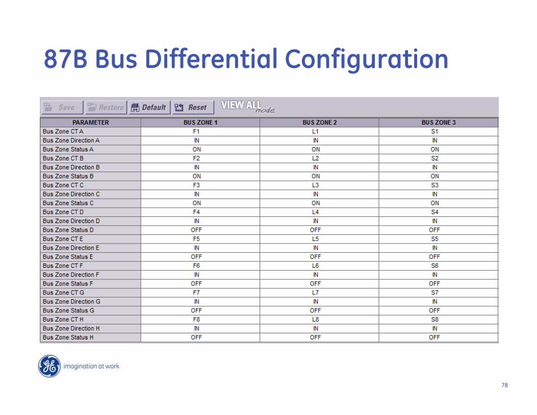
87B Bus Differential Configuration

79
How do we fix this monstrosity?
Let’s look at the phasors

80
We must maintain ABC rotation
Corrective action required

81
Paralleling Switchgear Trip

8282
The Story
• This relay trips every time I close the breaker
• It is tripping on Overcurrent.• You need to send me a new relay because
this one is obviously bad.

8383
Events
8484
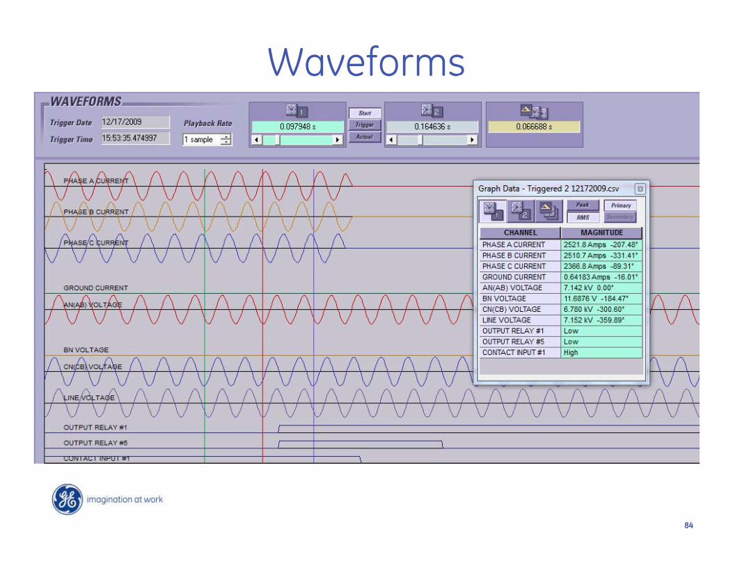
Waveforms
8585
How Microprocessor Relays Fail• Power Supplies – Failures there most likely mean the
relay is dead with no lights.• Processor failures – Failures there cause an alarm
which takes the relay out of service and illuminates an alarm LED.
• DSP failures – Failures there are rare, would typically raise an alarm and would show distorted metering values.
• Safe to say, this relay has NO problems, it is doing what it is suppose to do.

8686
Where is this relay and when is it tripping?
So what are you actually paralleling?
8787
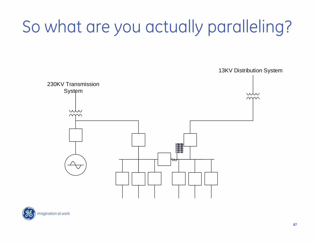
So what are you actually paralleling?
230KV Transmission System
13KV Distribution System
8888
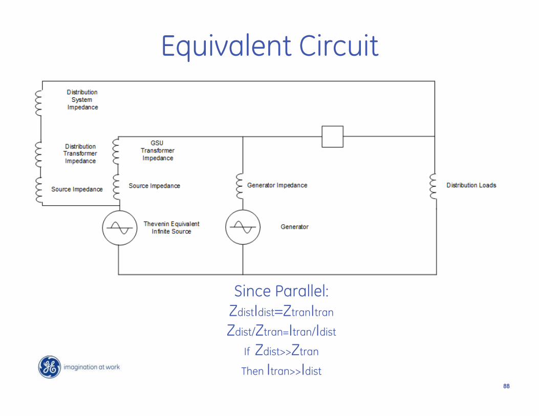
Equivalent Circuit
Since Parallel:ZdistIdist=ZtranItran
Zdist/Ztran=Itran/Idist
If Zdist>>Ztran
Then Itran>>Idist

8989
Possible Solutions• Can’t really raise the TOC pickup setting on the tie
breaker 750 and can’t really make the time delay longer• Could add controls to trip a selected breaker after all
three are closed.• Never parallel these two sources. Add mechanical
interlocks to prevent parallel of all three sources.

90
Synchronous Motor Trip on Power Factor

9191
The Story
• Synchronous motor is tripping on power factor pull-out
• Four of these compressors at the facility and is only happening to this compressor
• Started happening after we had the motor rebuilt.

9292
Synchronous Motor Theory

9393
Machine Excitation
Typical Generator Operation
Under-Excited Generator Operation
Synchronous Motor Operation
Induction Motor Operation
94
Synchronous Machines
• In an induction motor, the more load you have, the larger your slip.
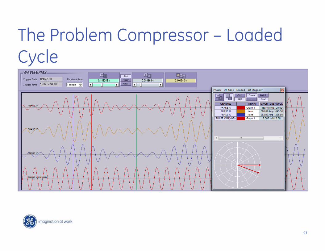
• In a synchronous motor, slip=0. The more load you have (without increasing excitation) the greater your (negative) power factor.
• To prevent slipping a pole (pull-out protection) you use power factor protection to trip when your load changes beyond what your exciter can keep up with.

9595
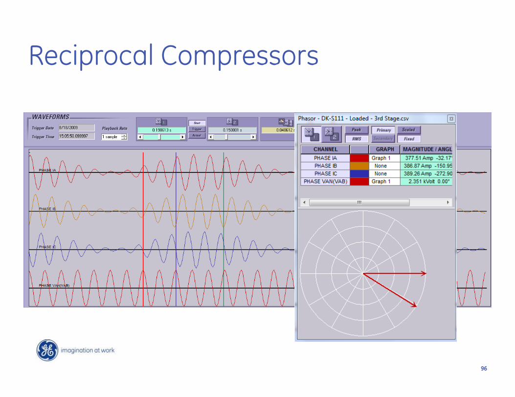
Reciprocal Compressors
9696
Reciprocal Compressors
9797
The Problem Compressor – Loaded Cycle

9898
The Problem Compressor – Un-Loaded Cycle
Within 60 Degrees of slipping a pole!

99
Problem
• This cannot be fixed with relay settings.• Must talk to motor manufacture about why this
compressor behaves this way.• A mechanical problem was causing the issue.
100
Substation heat pumps drops bus voltage by 1kV causes
capacitor bank trip

101101
The Story
• This relay is tripping on B phase voltage differential.
• Two relays in the station and they are both tripping on B phase voltage differential.
• The redundant relays are not tripping.

102102
Six Capacitor Banks – 2 Relays
16.7KV 600KVAR9 Elements/Can
0.8KV 167KVAR
83.13KV/115V
300/5
87
Protective Relay
00
0
144KV Line to Line

103103
Pre-Fault Values of the Trip
95,924-274(350.7130)=171=0.002pu
104104
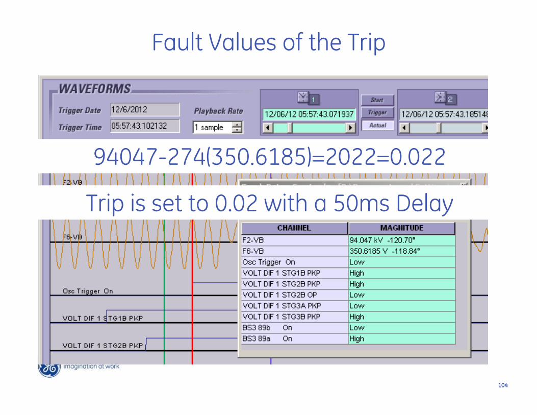
Fault Values of the Trip
94047-274(350.6185)=2022=0.022
Trip is set to 0.02 with a 50ms Delay

105105
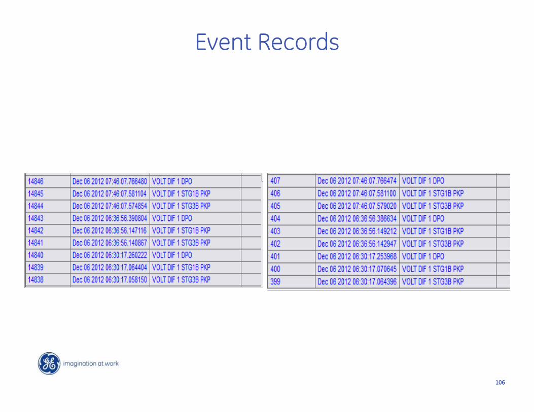
Event Records
106106
Event Records

107107
One of these things isn’t like the others!

108108

109109

110110

111111
112112
What can I do to prevent nuisance trips when the heat pump kicks on?
• Capacitor Bank Protection is set very sensitive. In this case at 2%.
• Can interlock the heat pump contactor with an 89B contact (humor intended)
• Can add a standard VT to provide voltages for protection.

113113
How would this effect other relaying
• Phase and Ground Distance Protection:• Could cause an element to over-reach if
a fault occurred at the same instance of a heat pump start.
• Probably wouldn’t affect steady state conditions unless extremely heavily loaded line.

114114
How would this effect other relaying
• Bus Under-voltage:• Probably would be unaffected because
of the duration.

115115
Lessons Learned
• Capacitor Bank Protection requires very sensitive settings.
• VT error can influence those setting.• We still spend most of our time talking
about instrument transformers.

116116
Questions ?