
Trouble shooting...Trouble shooting TROUBLE CAUSE REMEDY Air leaks. Low air pressure. Air pipes...
18
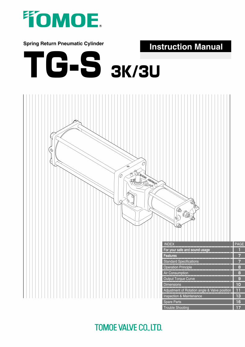
For your safe and sound usage For your safe and sound usage Features Features Standard Specifications Operation Principle Air Consumption Output Torque Curve Dimensions Adjustment of Rotation angle & Valve position Inspection & Maintenance Spare Parts Trouble Shooting INDEX PAGE Spring Return Pneumatic Cylinder TG-S 3K/3U Instruction Manual 1 7 7 8 8 9 10 11 13 16 17
Transcript of Trouble shooting...Trouble shooting TROUBLE CAUSE REMEDY Air leaks. Low air pressure. Air pipes...
For your safe and sound usageFor your safe and sound usage
FeaturesFeatures
Standard Specifications
Operation Principle
Air Consumption
Output Torque Curve
Dimensions
Adjustment of Rotation angle & Valve position
Inspection & Maintenance
Spare Parts
Trouble Shooting
INDEX PAGE
Spring Return Pneumatic Cylinder
TG-S 3K/3U
Instruction Manual
1778891011131617
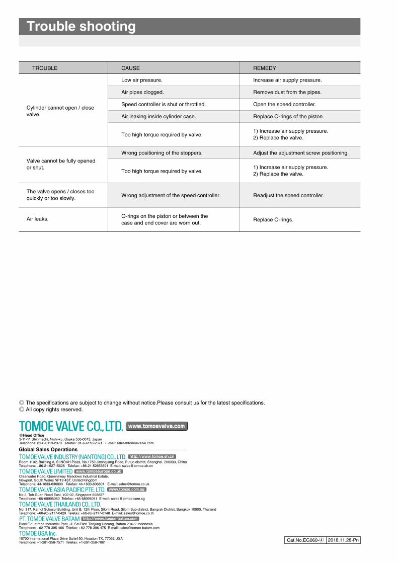
Trouble shooting
TROUBLE CAUSE REMEDY
Air leaks.
Low air pressure.
Air pipes clogged.
Speed controller is shut or throttled.
Air leaking inside cylinder case.
Too high torque required by valve.
Wrong positioning of the stoppers.
Too high torque required by valve.
Wrong adjustment of the speed controller.
O-rings on the piston or between thecase and end cover are worn out.
Increase air supply pressure.
Remove dust from the pipes.
Open the speed controller.
Replace O-rings of the piston.
1) Increase air supply pressure.2) Replace the valve.
Adjust the adjustment screw positioning.
1) Increase air supply pressure.2) Replace the valve.
Readjust the speed controller.
Replace O-rings.
Cylinder cannot open / closevalve.
Valve cannot be fully opened or shut.
The valve opens / closes tooquickly or too slowly.
◎ The specifications are subject to change without notice.Please consult us for the latest specifications.◎ All copy rights reserved.
Cat.No.EG060-④ 2018.11.28-Pn
●Head Office3-11-11 Shinmachi, Nishi-ku, Osaka 550-0013, JapanTelephone: 81-6-6110-2370 Telefax: 81-6-6110-2371 E-mail:[email protected]
Global Sales Operations
No. 317, Kamol Sukosol Building, Unit B, 12th Floor, Silom Road, Silom Sub-district, Bangrak District, Bangkok 10500, ThailandTelephone: +66-(0)-2117-0429 Telefax: +66-(0)-2117-0148 E-mail: [email protected]
TOMOE VALVE (THAILAND) CO., LTD.
15700 International Plaza Drive Suite150, Houston TX, 77032 USATelephone: +1-281-358-7571 Telefax: +1-281-358-7861
TOMOE USA Inc.
Room 1102, Building A, St.NOAH Plaza, No.1759 Jinshajiang Road, Putuo district, Shanghai. 200333, ChinaTelephone: +86-21-52715628 Telefax: +86-21-52653691 E-mail: [email protected]
TOMOE VALVE INDUSTRY (NANTONG) CO., LTD. http://www.tomoe.sh.cn
BlockF2 Latrade Industrial Park, JI. Sei Binti Tanjung Uncang, Batam 29422 IndonesiaTelephone: +62-778-395-466 Telefax: +62-778-396-475 E-mail: [email protected]
PT. TOMOE VALVE BATAM http://www.tomoe-batam.com
No 2, Toh Guan Road East, #02-02, Singapore 608837Telephone: +65-68995060 Telefax: +65-68995061 E-mail: [email protected]
TOMOE VALVE ASIA PACIFIC PTE. LTD. www.tomoe.com.sg
Clearwater Road, Queensway Meadows Industrial Estate,Newport, South Wales NP19 4ST, United KingdomTelephone: 44-1633-636800 Telefax: 44-1633-636801 E-mail:[email protected]
www.tomoeeurope.co.ukTOMOE VALVE LIMITED
www.tomoevalve.com
Note that the items listed here are to promote the correct usage of the product and to help prevent injury or damage.Carefully read this operation manual in its entirety then proceed to use the product correctly while adhering to the safety precautions.Furthermore, please be sure to also read the safety precautions for handling valves.
Please Observe the Following Safety Precautions
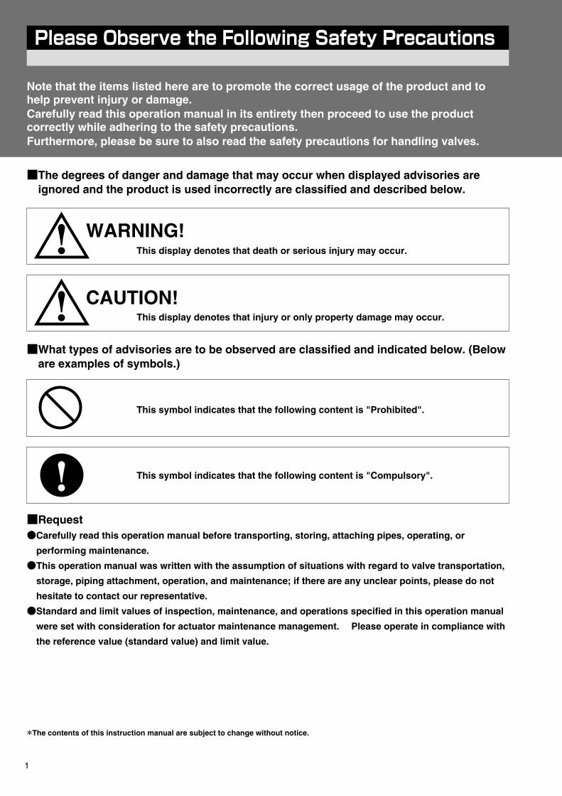
■The degrees of danger and damage that may occur when displayed advisories are ignored and the product is used incorrectly are classified and described below.
■What types of advisories are to be observed are classified and indicated below. (Below are examples of symbols.)
WARNING!This display denotes that death or serious injury may occur.
This symbol indicates that the following content is "Prohibited".
This symbol indicates that the following content is "Compulsory".
This display denotes that injury or only property damage may occur.
CAUTION!
■Request●Carefully read this operation manual before transporting, storing, attaching pipes, operating, or
performing maintenance.
●This operation manual was written with the assumption of situations with regard to valve transportation,
storage, piping attachment, operation, and maintenance; if there are any unclear points, please do not
hesitate to contact our representative.
●Standard and limit values of inspection, maintenance, and operations specified in this operation manual
were set with consideration for actuator maintenance management. Please operate in compliance with
the reference value (standard value) and limit value.
*The contents of this instruction manual are subject to change without notice.
1
WARNING! 1. Safety Measures
WARNING! 2. Installation and Operation Environment
1.1 Handling CylindersEnsure that only personnel with sufficient knowledge and experience handle cylinders.Compressed air can be dangerous if dealt with improperly. Ensure that only personnel with sufficient knowledge and experience assemble, operate, maintain, etc. machines and equipment that utilize pneumatic equipment.
1.2 Confirming Safe ConditionsNever attempt to handle machines or equipment, or remove machinery before safety is ensured.Please confirm that the actuated body’s anti-drop and run-away prevention measures are in place before inspecting or servicing machines and/or equipment. When removing machinery, confirm the aforementioned safety measures, then shut off the power to the supply air- which is the energy source - and any applicable equipment, exhaust all compressed air within the system, and make sure the valve’s internal pressure and temperature have dropped. Confirm operation safety precautions (cylinder operation, valve opening and shutting, electrical leakage, etc.) before restarting the machines and equipment.
1.3 Cylinder and Valve Attachments DesignEnsure that no thrust load or lateral load has joined to the cylinder’s output shaft when attaching. To prevent axial movement of the rotation shaft on the valve side from occurring, please install an independent stopper. Never apply the stopper on the rotation shaft to the cylinder’s output shaft. Furthermore, when the dimensions for insertion of the cylinder’s output shaft are too small, contact pressure on the fitting increases and the clearance gap will expand; it is possible that slippage may occur in the working position of the work load; therefore, it is important to ensure that the dimensions for insertion are adequate.
1.4 Mechanical BackupIf loss of all functionality due to pneumatic pressure occurs, to safely activate the cylinder, please adopt a method of operation which utilizes a different energy source, such as a Springback cylinder (hereinafter referred to as a single-acting cylinder).
2.1 Maximum Operating SpeedDo not exceed the maximum operating speed listed in the catalog. With regard to work load conditions, the cylinder may break or become damaged due to inertial force. Furthermore, water hammer may occur even if within the range noted in the catalog, due to pipe and valve operating conditions.
2.2 Installation SpacePerform installation work and maintenance at easy-to-work sites/locations.
2.3 Operation Confirmation ProcedureFirst, verify that the cylinder unit itself is not malfunctioning. Next, ensure that the thrust load and lateral loads of the output shaft are not joined when coupled with the work load. Also, confirm that there are no abnormalities such as air leaks in the output shaft and piping connections, then proceed to install the equipment. Lastly, confirm operation of all the equipment.
2.4 Residual PressureAs there is a jet of compressed air going to the cylinder, unexpected movements of the cylinder may occur due to residual pressure even after air has been exhausted from the equipment; it is important to understand the risks when operating, even during installation.
2.5 TrainingEnsure that installation and maintenance of cylinders is performed by personnel with sufficient knowledge and experience.
2
Note that the items listed here are to promote the correct usage of the product and to help prevent injury or damage.Carefully read this operation manual in its entirety then proceed to use the product correctly while adhering to the safety precautions.Furthermore, please be sure to also read the safety precautions for handling valves.
Please Observe the Following Safety Precautions
■The degrees of danger and damage that may occur when displayed advisories are ignored and the product is used incorrectly are classified and described below.
■What types of advisories are to be observed are classified and indicated below. (Below are examples of symbols.)
WARNING!This display denotes that death or serious injury may occur.
This symbol indicates that the following content is "Prohibited".
This symbol indicates that the following content is "Compulsory".
This display denotes that injury or only property damage may occur.
CAUTION!
■Request●Carefully read this operation manual before transporting, storing, attaching pipes, operating, or
performing maintenance.
●This operation manual was written with the assumption of situations with regard to valve transportation,
storage, piping attachment, operation, and maintenance; if there are any unclear points, please do not
hesitate to contact our representative.
●Standard and limit values of inspection, maintenance, and operations specified in this operation manual
were set with consideration for actuator maintenance management. Please operate in compliance with
the reference value (standard value) and limit value.
*The contents of this instruction manual are subject to change without notice.
1
WARNING! 3. Maintenance and Inspection
Removing the cover and disassembling is dangerous! Never attempt to do this.
2.6 Cylinder Installation SitesIf installing at a site that requires special support for functional specification compliance, regulatory compliance, etc. - as noted in the following - please contact our sales representative before adopting usage of the cylinder.1) When there are unique specifications that are not listed in the catalog.2) When great risk to personnel, property, or the environment are projected.
2.7 Vibration and Shock during PipingMake sure that strong force, impact from objects, or any sort of shock is not applied to the cylinder, ancillary devices, or air pipes. Rough handling may result in abnormal performance. For example, deformation and damage to parts caused by climbing on, hitting, dropping the cylinder parts may cause the cylinder’s bore to warp, which can result in malfunction. Furthermore, bending and warping of the output shaft will result in damage to the O-ring, which in turn causes air leaks. In the event any dents or scratches caused by shock are found, as a safety measure, it is advised to stop operation and replace the damaged parts.
2.8 Installation Environment2.8.1 Environment
1) Take caution with regard to the environment where the cylinder will be installed. Avoid installation at sites that may expose the cylinder to wind, rain, direct sunlight, salt damage, corrosive gases, chemical fluids, organic solvents and vapor. However, there are certain environmental conditions where corrosion prevention is possible; if this case applies to you, please contact our sales representative.
2) If there is possibility of direct exposure to radiant heat or chemicals, ensure protection of the cylinder and ancillary devices by covering it. According to the type of accessories, discoloration may occur when exposed to direct sunlight.
3) When installing a single-acting cylinder outdoors or at a site where it may be exposed to water, ensure that the exhaust port’s elbow, located on the opposite side from the air supply port, is facing down to prevent sand, rain water, rubbish, etc. from penetrating it.
2.8.2 TemperaturePlease use cylinders within the listed temperature range along while taking into consideration the ambient temperature and compressed air supply of the installation site.1) Compressed air near air compressors can register fairly high temperatures, which may result in thermal
degradation of the O-ring, as well as malfunction caused by the differences in thermal expansion of components.
2) In sites with temperatures are near 0℃, dehumidify compressed air with an air dyer. If not properly dehumidified, excessive amounts of water in the equipment will freeze when not in use, and may cause malfunction.
2.8.3 Vibration and Shock1) If a cylinder is to be used at a site with excessive vibration and shock, confirm vibration and shock conditions
(especially the acceleration value) then contact our sales representative for advice.2) In sites where there is vibration, ensure that locks are applied to the cylinder’s attachments and connectors,
and are securely fastened. This is important especially when operating in high-frequency, and to consider fatigue resistance and fasten accordingly.
3) In sites where there is vibration, it is important to conduct periodic inspections of fasteners, which is to be conducted after starting operation, to ensure that no loosening or warping has occurred, and make sure to tighten screws if loose. If attachments and connecters are removed the cylinder may actuate in an unexpected direction, which is dangerous to personnel and machinery and equipment.
4) Abnormal vibrations left unattended are the leading cause of breakdown. Affix piping to some sort of support to prevent vibration.
3.1 Cylinder Maintenance and Inspection1) Please follow the procedure for assembly and disassembly written in this operation manual as a guideline for
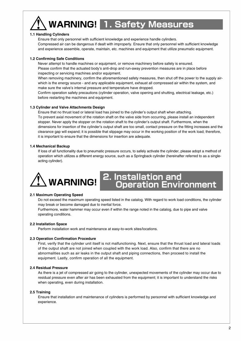
maintenance and inspection.2) Never loosen the bolt that fastens the cover in circumstances where
a cylinder or valve may start moving, or when there is pneumatic pressure. These particular bolts have been fastened with a specified tightening torque.
3) As for single-acting cylinders, even if there is no pneumatic pressure, if the bolt that attaches the cover is loosened the internal spring may force the cover to fly off, which can result in damage or injury. Never loosen this bolt. If there are any abnormalities, please contact our sales representative.
4) Never operate single-acting cylinders with levers or spanner-wrenches. If a cylinder output shaft operates with a spanner-wrench or double-acting manual lever the force of the spring may cause the cylinder to be pushed back, and can be dangerous. Never attempt this type of operation. (Use the side handle.)
3
CAUTION! 1. Transportation and Storage
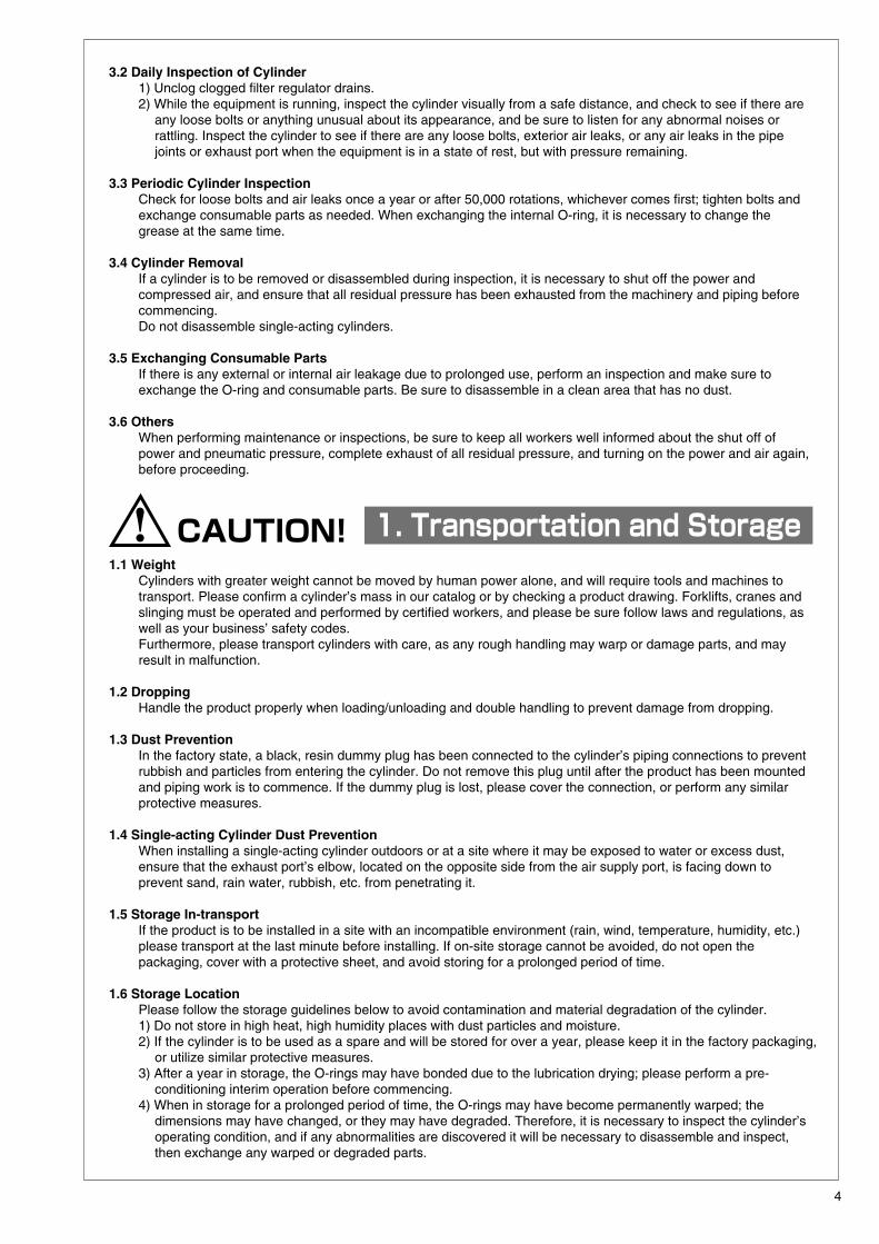
3.2 Daily Inspection of Cylinder1) Unclog clogged filter regulator drains.2) While the equipment is running, inspect the cylinder visually from a safe distance, and check to see if there are
any loose bolts or anything unusual about its appearance, and be sure to listen for any abnormal noises or rattling. Inspect the cylinder to see if there are any loose bolts, exterior air leaks, or any air leaks in the pipe joints or exhaust port when the equipment is in a state of rest, but with pressure remaining.
3.3 Periodic Cylinder InspectionCheck for loose bolts and air leaks once a year or after 50,000 rotations, whichever comes first; tighten bolts and exchange consumable parts as needed. When exchanging the internal O-ring, it is necessary to change the grease at the same time.
3.4 Cylinder RemovalIf a cylinder is to be removed or disassembled during inspection, it is necessary to shut off the power and compressed air, and ensure that all residual pressure has been exhausted from the machinery and piping before commencing. Do not disassemble single-acting cylinders.
3.5 Exchanging Consumable PartsIf there is any external or internal air leakage due to prolonged use, perform an inspection and make sure to exchange the O-ring and consumable parts. Be sure to disassemble in a clean area that has no dust.
3.6 OthersWhen performing maintenance or inspections, be sure to keep all workers well informed about the shut off of power and pneumatic pressure, complete exhaust of all residual pressure, and turning on the power and air again, before proceeding.
1.1 WeightCylinders with greater weight cannot be moved by human power alone, and will require tools and machines to transport. Please confirm a cylinder’s mass in our catalog or by checking a product drawing. Forklifts, cranes and slinging must be operated and performed by certified workers, and please be sure follow laws and regulations, as well as your business’ safety codes. Furthermore, please transport cylinders with care, as any rough handling may warp or damage parts, and may result in malfunction.
1.2 DroppingHandle the product properly when loading/unloading and double handling to prevent damage from dropping.
1.3 Dust PreventionIn the factory state, a black, resin dummy plug has been connected to the cylinder’s piping connections to prevent rubbish and particles from entering the cylinder. Do not remove this plug until after the product has been mounted and piping work is to commence. If the dummy plug is lost, please cover the connection, or perform any similar protective measures.
1.4 Single-acting Cylinder Dust PreventionWhen installing a single-acting cylinder outdoors or at a site where it may be exposed to water or excess dust, ensure that the exhaust port’s elbow, located on the opposite side from the air supply port, is facing down to prevent sand, rain water, rubbish, etc. from penetrating it.
1.5 Storage In-transportIf the product is to be installed in a site with an incompatible environment (rain, wind, temperature, humidity, etc.) please transport at the last minute before installing. If on-site storage cannot be avoided, do not open the packaging, cover with a protective sheet, and avoid storing for a prolonged period of time.
1.6 Storage LocationPlease follow the storage guidelines below to avoid contamination and material degradation of the cylinder.1) Do not store in high heat, high humidity places with dust particles and moisture.2) If the cylinder is to be used as a spare and will be stored for over a year, please keep it in the factory packaging,
or utilize similar protective measures.3) After a year in storage, the O-rings may have bonded due to the lubrication drying; please perform a pre-
conditioning interim operation before commencing.4) When in storage for a prolonged period of time, the O-rings may have become permanently warped; the
dimensions may have changed, or they may have degraded. Therefore, it is necessary to inspect the cylinder’s operating condition, and if any abnormalities are discovered it will be necessary to disassemble and inspect, then exchange any warped or degraded parts.
4
WARNING! 3. Maintenance and Inspection
Removing the cover and disassembling is dangerous! Never attempt to do this.
2.6 Cylinder Installation SitesIf installing at a site that requires special support for functional specification compliance, regulatory compliance, etc. - as noted in the following - please contact our sales representative before adopting usage of the cylinder.1) When there are unique specifications that are not listed in the catalog.2) When great risk to personnel, property, or the environment are projected.
2.7 Vibration and Shock during PipingMake sure that strong force, impact from objects, or any sort of shock is not applied to the cylinder, ancillary devices, or air pipes. Rough handling may result in abnormal performance. For example, deformation and damage to parts caused by climbing on, hitting, dropping the cylinder parts may cause the cylinder’s bore to warp, which can result in malfunction. Furthermore, bending and warping of the output shaft will result in damage to the O-ring, which in turn causes air leaks. In the event any dents or scratches caused by shock are found, as a safety measure, it is advised to stop operation and replace the damaged parts.
2.8 Installation Environment2.8.1 Environment
1) Take caution with regard to the environment where the cylinder will be installed. Avoid installation at sites that may expose the cylinder to wind, rain, direct sunlight, salt damage, corrosive gases, chemical fluids, organic solvents and vapor. However, there are certain environmental conditions where corrosion prevention is possible; if this case applies to you, please contact our sales representative.
2) If there is possibility of direct exposure to radiant heat or chemicals, ensure protection of the cylinder and ancillary devices by covering it. According to the type of accessories, discoloration may occur when exposed to direct sunlight.
3) When installing a single-acting cylinder outdoors or at a site where it may be exposed to water, ensure that the exhaust port’s elbow, located on the opposite side from the air supply port, is facing down to prevent sand, rain water, rubbish, etc. from penetrating it.
2.8.2 TemperaturePlease use cylinders within the listed temperature range along while taking into consideration the ambient temperature and compressed air supply of the installation site.1) Compressed air near air compressors can register fairly high temperatures, which may result in thermal
degradation of the O-ring, as well as malfunction caused by the differences in thermal expansion of components.
2) In sites with temperatures are near 0℃, dehumidify compressed air with an air dyer. If not properly dehumidified, excessive amounts of water in the equipment will freeze when not in use, and may cause malfunction.
2.8.3 Vibration and Shock1) If a cylinder is to be used at a site with excessive vibration and shock, confirm vibration and shock conditions
(especially the acceleration value) then contact our sales representative for advice.2) In sites where there is vibration, ensure that locks are applied to the cylinder’s attachments and connectors,
and are securely fastened. This is important especially when operating in high-frequency, and to consider fatigue resistance and fasten accordingly.
3) In sites where there is vibration, it is important to conduct periodic inspections of fasteners, which is to be conducted after starting operation, to ensure that no loosening or warping has occurred, and make sure to tighten screws if loose. If attachments and connecters are removed the cylinder may actuate in an unexpected direction, which is dangerous to personnel and machinery and equipment.
4) Abnormal vibrations left unattended are the leading cause of breakdown. Affix piping to some sort of support to prevent vibration.
3.1 Cylinder Maintenance and Inspection1) Please follow the procedure for assembly and disassembly written in this operation manual as a guideline for
maintenance and inspection.2) Never loosen the bolt that fastens the cover in circumstances where
a cylinder or valve may start moving, or when there is pneumatic pressure. These particular bolts have been fastened with a specified tightening torque.
3) As for single-acting cylinders, even if there is no pneumatic pressure, if the bolt that attaches the cover is loosened the internal spring may force the cover to fly off, which can result in damage or injury. Never loosen this bolt. If there are any abnormalities, please contact our sales representative.
4) Never operate single-acting cylinders with levers or spanner-wrenches. If a cylinder output shaft operates with a spanner-wrench or double-acting manual lever the force of the spring may cause the cylinder to be pushed back, and can be dangerous. Never attempt this type of operation. (Use the side handle.)
3
CAUTION! 2 .Piping and Installation
CAUTION! 3 .Air Supply
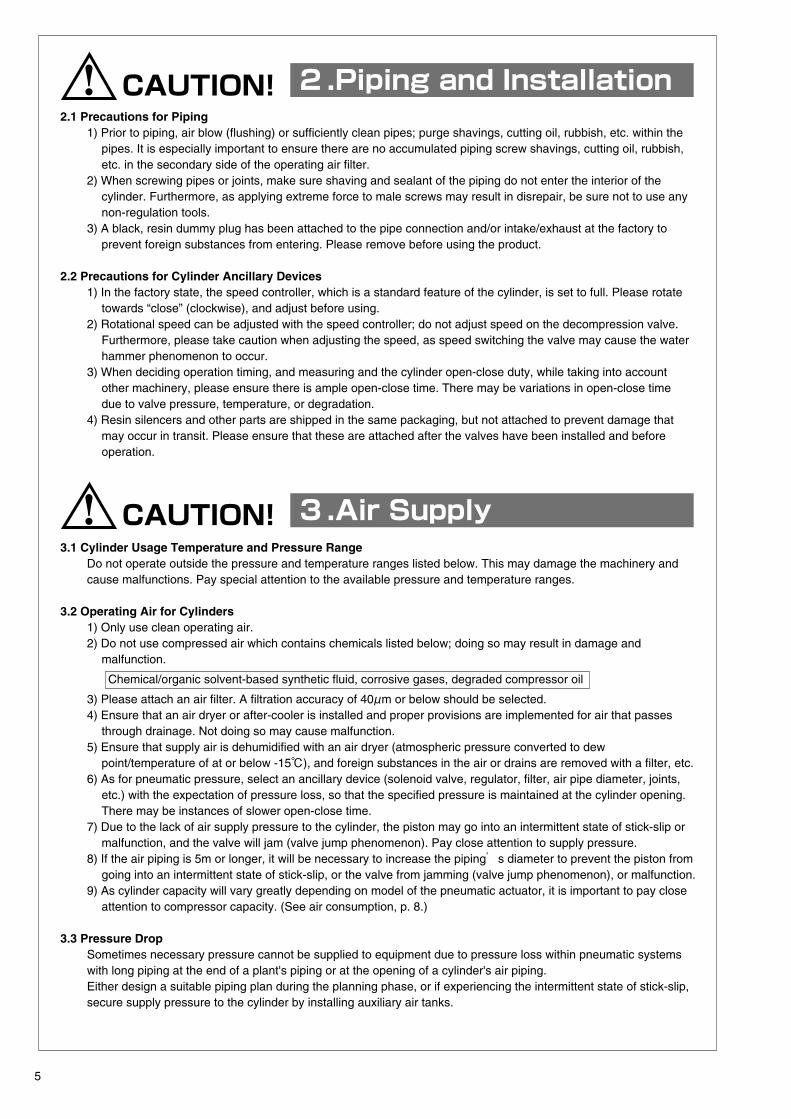
2.1 Precautions for Piping1) Prior to piping, air blow (flushing) or sufficiently clean pipes; purge shavings, cutting oil, rubbish, etc. within the
pipes. It is especially important to ensure there are no accumulated piping screw shavings, cutting oil, rubbish, etc. in the secondary side of the operating air filter.
2) When screwing pipes or joints, make sure shaving and sealant of the piping do not enter the interior of the cylinder. Furthermore, as applying extreme force to male screws may result in disrepair, be sure not to use any non-regulation tools.
3) A black, resin dummy plug has been attached to the pipe connection and/or intake/exhaust at the factory to prevent foreign substances from entering. Please remove before using the product.
2.2 Precautions for Cylinder Ancillary Devices1) In the factory state, the speed controller, which is a standard feature of the cylinder, is set to full. Please rotate
towards “close” (clockwise), and adjust before using.2) Rotational speed can be adjusted with the speed controller; do not adjust speed on the decompression valve.
Furthermore, please take caution when adjusting the speed, as speed switching the valve may cause the water hammer phenomenon to occur.
3) When deciding operation timing, and measuring and the cylinder open-close duty, while taking into account other machinery, please ensure there is ample open-close time. There may be variations in open-close time due to valve pressure, temperature, or degradation.
4) Resin silencers and other parts are shipped in the same packaging, but not attached to prevent damage that may occur in transit. Please ensure that these are attached after the valves have been installed and before operation.
3.1 Cylinder Usage Temperature and Pressure RangeDo not operate outside the pressure and temperature ranges listed below. This may damage the machinery and cause malfunctions. Pay special attention to the available pressure and temperature ranges.
3.2 Operating Air for Cylinders1) Only use clean operating air.2) Do not use compressed air which contains chemicals listed below; doing so may result in damage and
malfunction.
Chemical/organic solvent-based synthetic fluid, corrosive gases, degraded compressor oil
3) Please attach an air filter. A filtration accuracy of 40μm or below should be selected.4) Ensure that an air dryer or after-cooler is installed and proper provisions are implemented for air that passes
through drainage. Not doing so may cause malfunction.5) Ensure that supply air is dehumidified with an air dryer (atmospheric pressure converted to dew
point/temperature of at or below -15℃), and foreign substances in the air or drains are removed with a filter, etc.6) As for pneumatic pressure, select an ancillary device (solenoid valve, regulator, filter, air pipe diameter, joints,
etc.) with the expectation of pressure loss, so that the specified pressure is maintained at the cylinder opening. There may be instances of slower open-close time.
7) Due to the lack of air supply pressure to the cylinder, the piston may go into an intermittent state of stick-slip or malfunction, and the valve will jam (valve jump phenomenon). Pay close attention to supply pressure.
8) If the air piping is 5m or longer, it will be necessary to increase the piping’s diameter to prevent the piston from going into an intermittent state of stick-slip, or the valve from jamming (valve jump phenomenon), or malfunction.
9) As cylinder capacity will vary greatly depending on model of the pneumatic actuator, it is important to pay close attention to compressor capacity. (See air consumption, p. 8.)
3.3 Pressure DropSometimes necessary pressure cannot be supplied to equipment due to pressure loss within pneumatic systems with long piping at the end of a plant's piping or at the opening of a cylinder's air piping. Either design a suitable piping plan during the planning phase, or if experiencing the intermittent state of stick-slip, secure supply pressure to the cylinder by installing auxiliary air tanks.
5
CAUTION! 4 . Lubricating
CAUTION! 5 .Usage and Adjustment
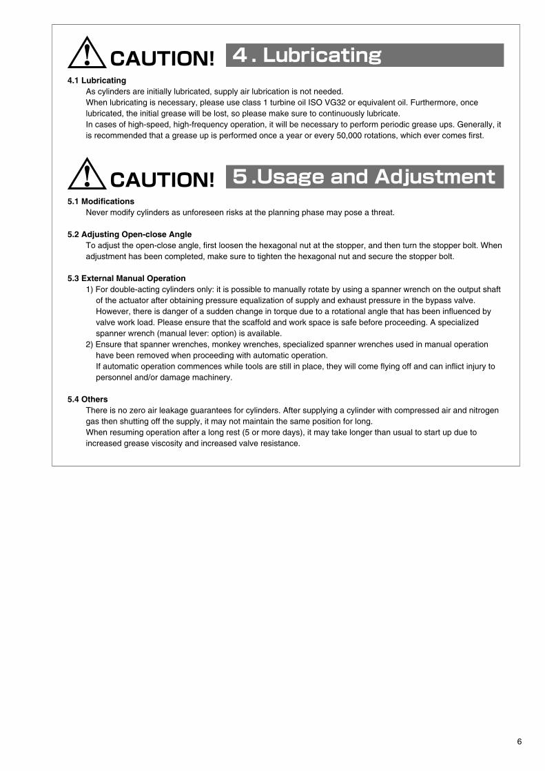
4.1 LubricatingAs cylinders are initially lubricated, supply air lubrication is not needed. When lubricating is necessary, please use class 1 turbine oil ISO VG32 or equivalent oil. Furthermore, once lubricated, the initial grease will be lost, so please make sure to continuously lubricate. In cases of high-speed, high-frequency operation, it will be necessary to perform periodic grease ups. Generally, it is recommended that a grease up is performed once a year or every 50,000 rotations, which ever comes first.
5.1 ModificationsNever modify cylinders as unforeseen risks at the planning phase may pose a threat.
5.2 Adjusting Open-close AngleTo adjust the open-close angle, first loosen the hexagonal nut at the stopper, and then turn the stopper bolt. When adjustment has been completed, make sure to tighten the hexagonal nut and secure the stopper bolt.
5.3 External Manual Operation1) For double-acting cylinders only: it is possible to manually rotate by using a spanner wrench on the output shaft
of the actuator after obtaining pressure equalization of supply and exhaust pressure in the bypass valve. However, there is danger of a sudden change in torque due to a rotational angle that has been influenced by valve work load. Please ensure that the scaffold and work space is safe before proceeding. A specialized spanner wrench (manual lever: option) is available.
2) Ensure that spanner wrenches, monkey wrenches, specialized spanner wrenches used in manual operation have been removed when proceeding with automatic operation.If automatic operation commences while tools are still in place, they will come flying off and can inflict injury to personnel and/or damage machinery.
5.4 OthersThere is no zero air leakage guarantees for cylinders. After supplying a cylinder with compressed air and nitrogen gas then shutting off the supply, it may not maintain the same position for long.When resuming operation after a long rest (5 or more days), it may take longer than usual to start up due to increased grease viscosity and increased valve resistance.
6
CAUTION! 2 .Piping and Installation
CAUTION! 3 .Air Supply
2.1 Precautions for Piping1) Prior to piping, air blow (flushing) or sufficiently clean pipes; purge shavings, cutting oil, rubbish, etc. within the
pipes. It is especially important to ensure there are no accumulated piping screw shavings, cutting oil, rubbish, etc. in the secondary side of the operating air filter.
2) When screwing pipes or joints, make sure shaving and sealant of the piping do not enter the interior of the cylinder. Furthermore, as applying extreme force to male screws may result in disrepair, be sure not to use any non-regulation tools.
3) A black, resin dummy plug has been attached to the pipe connection and/or intake/exhaust at the factory to prevent foreign substances from entering. Please remove before using the product.
2.2 Precautions for Cylinder Ancillary Devices1) In the factory state, the speed controller, which is a standard feature of the cylinder, is set to full. Please rotate
towards “close” (clockwise), and adjust before using.2) Rotational speed can be adjusted with the speed controller; do not adjust speed on the decompression valve.
Furthermore, please take caution when adjusting the speed, as speed switching the valve may cause the water hammer phenomenon to occur.
3) When deciding operation timing, and measuring and the cylinder open-close duty, while taking into account other machinery, please ensure there is ample open-close time. There may be variations in open-close time due to valve pressure, temperature, or degradation.
4) Resin silencers and other parts are shipped in the same packaging, but not attached to prevent damage that may occur in transit. Please ensure that these are attached after the valves have been installed and before operation.
3.1 Cylinder Usage Temperature and Pressure RangeDo not operate outside the pressure and temperature ranges listed below. This may damage the machinery and cause malfunctions. Pay special attention to the available pressure and temperature ranges.
3.2 Operating Air for Cylinders1) Only use clean operating air.2) Do not use compressed air which contains chemicals listed below; doing so may result in damage and
malfunction.
Chemical/organic solvent-based synthetic fluid, corrosive gases, degraded compressor oil
3) Please attach an air filter. A filtration accuracy of 40μm or below should be selected.4) Ensure that an air dryer or after-cooler is installed and proper provisions are implemented for air that passes
through drainage. Not doing so may cause malfunction.5) Ensure that supply air is dehumidified with an air dryer (atmospheric pressure converted to dew
point/temperature of at or below -15℃), and foreign substances in the air or drains are removed with a filter, etc.6) As for pneumatic pressure, select an ancillary device (solenoid valve, regulator, filter, air pipe diameter, joints,
etc.) with the expectation of pressure loss, so that the specified pressure is maintained at the cylinder opening. There may be instances of slower open-close time.
7) Due to the lack of air supply pressure to the cylinder, the piston may go into an intermittent state of stick-slip or malfunction, and the valve will jam (valve jump phenomenon). Pay close attention to supply pressure.
8) If the air piping is 5m or longer, it will be necessary to increase the piping’s diameter to prevent the piston from going into an intermittent state of stick-slip, or the valve from jamming (valve jump phenomenon), or malfunction.
9) As cylinder capacity will vary greatly depending on model of the pneumatic actuator, it is important to pay close attention to compressor capacity. (See air consumption, p. 8.)
3.3 Pressure DropSometimes necessary pressure cannot be supplied to equipment due to pressure loss within pneumatic systems with long piping at the end of a plant's piping or at the opening of a cylinder's air piping. Either design a suitable piping plan during the planning phase, or if experiencing the intermittent state of stick-slip, secure supply pressure to the cylinder by installing auxiliary air tanks.
5
Standard Specifications
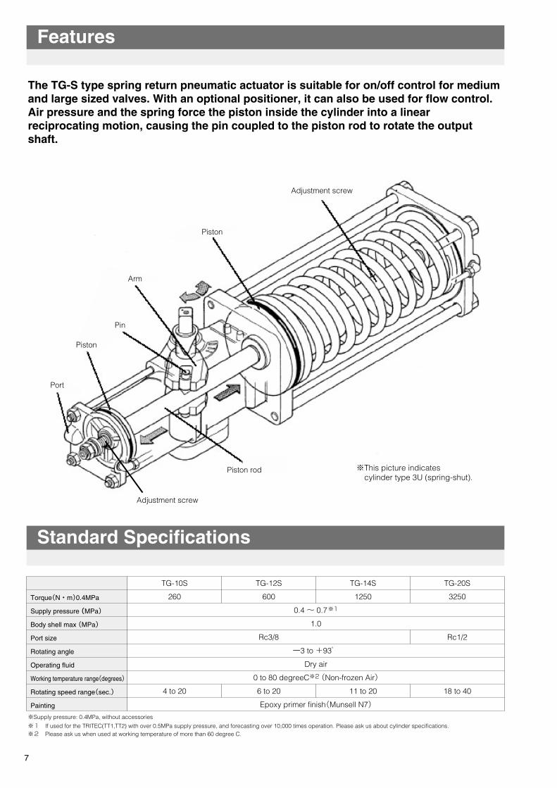
The TG-S type spring return pneumatic actuator is suitable for on/off control for medium and large sized valves. With an optional positioner, it can also be used for flow control. Air pressure and the spring force the piston inside the cylinder into a linear reciprocating motion, causing the pin coupled to the piston rod to rotate the output shaft.
※Supply pressure: 0.4MPa, without accessories
TG-10S
260
4 to 20
Adjustment screw
Piston
Piston
Piston rod
Pin
Port
Adjustment screw
※This picture indicates cylinder type 3U (spring-shut).
Arm
TG-12S
600
Rc3/8
6 to 20
TG-14S
1250
11 to 20
TG-20S
3250
Rc1/2
18 to 40
Torque(N・m)0.4MPa
Supply pressure (MPa)
Body shell max (MPa)
Port size
Rotating angle
Operating fluid
Working temperature range(degrees)
Rotating speed range(sec.)
Painting
0.4 ~ 0.7※1
1.0
ー3 to +93°
Dry air
0 to 80 degreeC※2 (Non-frozen Air)
Epoxy primer finish(Munsell N7)
Features
※1 If used for the TRITEC(TT1,TT2) with over 0.5MPa supply pressure, and forecasting over 10,000 times operation. Please ask us about cylinder specifications.※2 Please ask us when used at working temperature of more than 60 degree C.
7
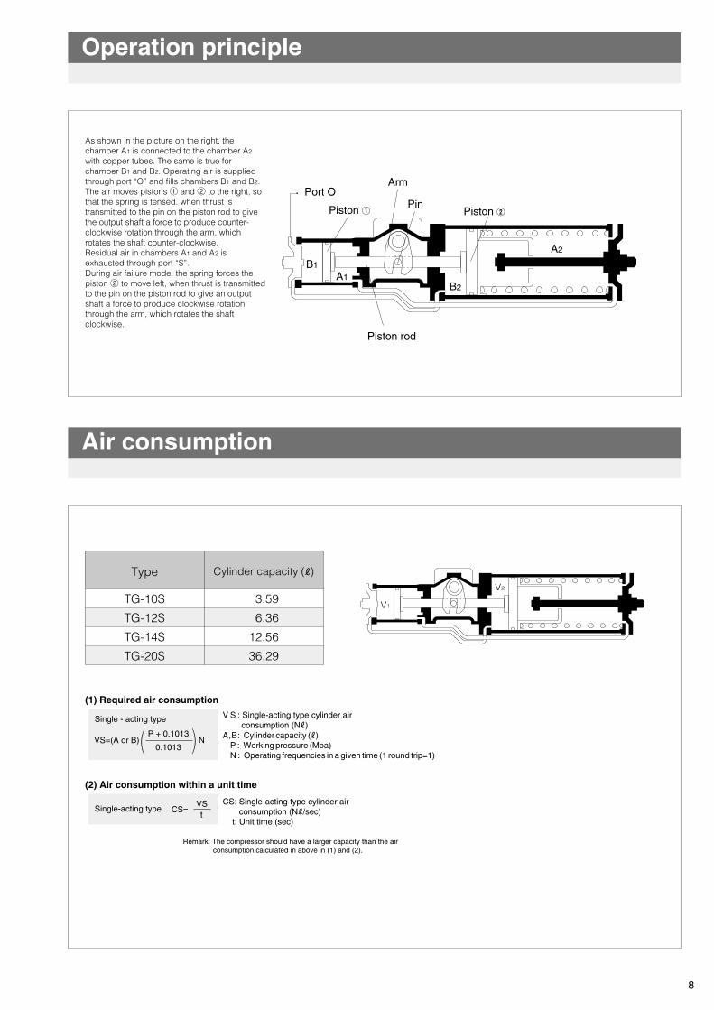
As shown in the picture on the right, the chamber A1 is connected to the chamber A2 with copper tubes. The same is true for chamber B1 and B2. Operating air is supplied through port “O” and fills chambers B1 and B2. The air moves pistons ① and ② to the right, so that the spring is tensed. when thrust is transmitted to the pin on the piston rod to give the output shaft a force to produce counter-clockwise rotation through the arm, which rotates the shaft counter-clockwise.Residual air in chambers A1 and A2 is exhausted through port “S”.During air failure mode, the spring forces the piston ② to move left, when thrust is transmitted to the pin on the piston rod to give an output shaft a force to produce clockwise rotation through the arm, which rotates the shaft clockwise.
Port OArm
Pin
Piston rod
Piston ②
Adjust Screw
A1
A2
B1
B2
TG-10S
TG-12S
TG-14S
TG-20S
3.59
6.36
12.56
36.29
Piston ①
V1
V2
V S : Single-acting type cylinder air consumption (Nℓ)A,B: Cylinder capacity (ℓ)
P : Working pressure (Mpa)N : Operating frequencies in a given time (1 round trip=1)
(1) Required air consumption
(2) Air consumption within a unit time
Single - acting type
VS=(A or B)P + 0.1013
0.1013N
Type Cylinder capacity (ℓ)
Air consumption
Operation principle
8
CS: Single-acting type cylinder air consumption (Nℓ/sec) t: Unit time (sec)
Single-acting type CS=VSt
Remark: The compressor should have a larger capacity than the air consumption calculated in above in (1) and (2).
Standard Specifications
The TG-S type spring return pneumatic actuator is suitable for on/off control for medium and large sized valves. With an optional positioner, it can also be used for flow control. Air pressure and the spring force the piston inside the cylinder into a linear reciprocating motion, causing the pin coupled to the piston rod to rotate the output shaft.
※Supply pressure: 0.4MPa, without accessories
TG-10S
260
4 to 20
Adjustment screw
Piston
Piston
Piston rod
Pin
Port
Adjustment screw
※This picture indicates cylinder type 3U (spring-shut).
Arm
TG-12S
600
Rc3/8
6 to 20
TG-14S
1250
11 to 20
TG-20S
3250
Rc1/2
18 to 40
Torque(N・m)0.4MPa
Supply pressure (MPa)
Body shell max (MPa)
Port size
Rotating angle
Operating fluid
Working temperature range(degrees)
Rotating speed range(sec.)
Painting
0.4 ~ 0.7※1
1.0
ー3 to +93°
Dry air
0 to 80 degreeC※2 (Non-frozen Air)
Epoxy primer finish(Munsell N7)
Features
※1 If used for the TRITEC(TT1,TT2) with over 0.5MPa supply pressure, and forecasting over 10,000 times operation. Please ask us about cylinder specifications.※2 Please ask us when used at working temperature of more than 60 degree C.
7
0° 10° 20° 30° 40° 50° 60° 70° 80° 90°100
1000
3250
1250
600
260
5000
10000
500
TG-20S
TG-14S
TG-12S
TG-10S
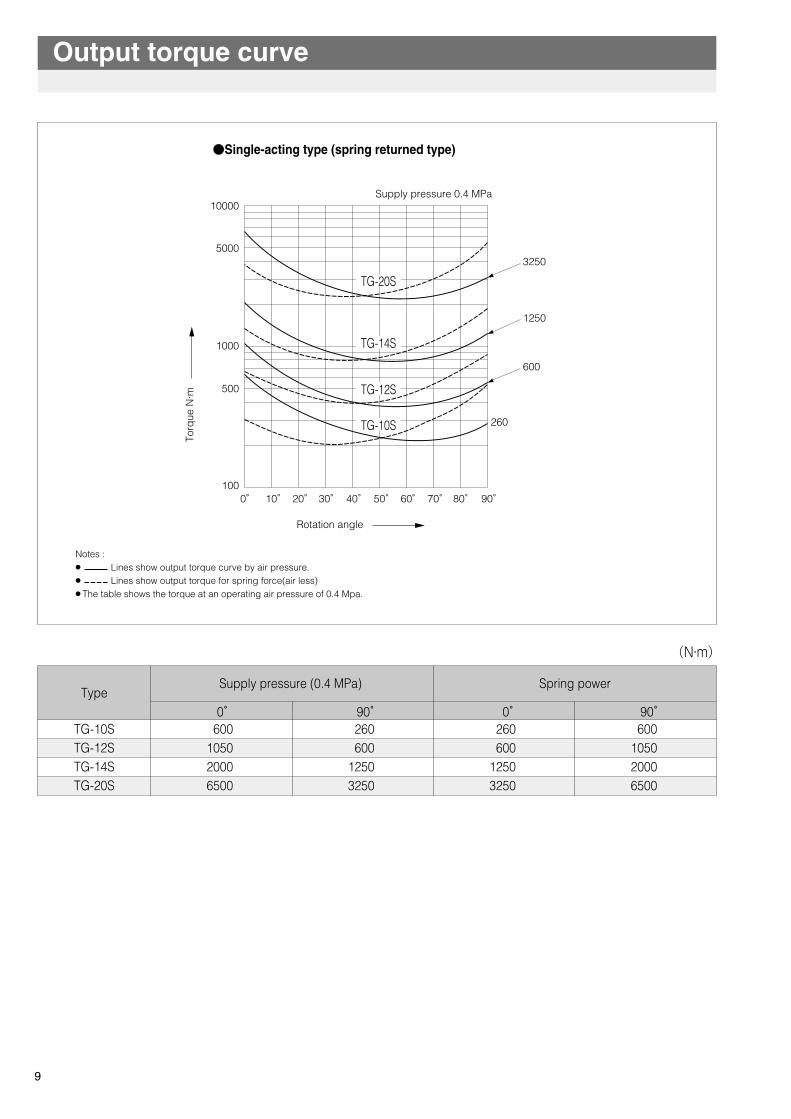
Output torque curve
●Single-acting type (spring returned type)
Rotation angle
Torq
ue N
·mSupply pressure 0.4 MPa
9
TG-10STG-12STG-14STG-20S
Supply pressure (0.4 MPa) Spring powerType
600 1050 2000 6500
0゚260 600
1250 3250
90゚260 600
1250 3250
0゚600
1050 2000 6500
90゚
(N・m)
Notes :● Lines show output torque curve by air pressure.● Lines show output torque for spring force(air less)● The table shows the torque at an operating air pressure of 0.4 Mpa.
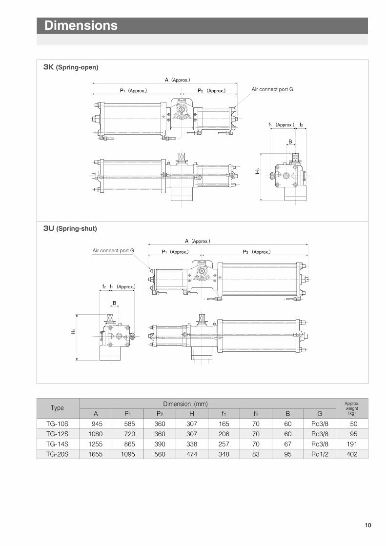
TG-10S
TG-12S
TG-14S
TG-20S
945
1080
1255
1655
585
720
865
1095
307
307
338
474
360
360
390
560
165
206
257
348
70
70
70
83
60
60
67
95
Rc3/8
Rc3/8
Rc3/8
Rc1/2
50
95
191
402
3K (Spring-open)
3U (Spring-shut)
A H f1 f2 B GP2P1
A(Approx.)
P1(Approx.) P2 (Approx.)
f1 (Approx.)f2
Air connect port G
OS
H3
B
A(Approx.)
OS
P2 (Approx.)P1(Approx.)
H3
B
f1 (Approx.) f2
Air connect port G
Approx.weight(kg)
Dimension (mm)Type
Dimensions
10
0° 10° 20° 30° 40° 50° 60° 70° 80° 90°100
1000
3250
1250
600
260
5000
10000
500
TG-20S
TG-14S
TG-12S
TG-10S
Output torque curve
●Single-acting type (spring returned type)
Rotation angle
Torq
ue N
·m
Supply pressure 0.4 MPa
9
TG-10STG-12STG-14STG-20S
Supply pressure (0.4 MPa) Spring powerType
600 1050 2000 6500
0゚260 600
1250 3250
90゚260 600
1250 3250
0゚600
1050 2000 6500
90゚
(N・m)
Notes :● Lines show output torque curve by air pressure.● Lines show output torque for spring force(air less)● The table shows the torque at an operating air pressure of 0.4 Mpa.
ADJUSTMENT
11
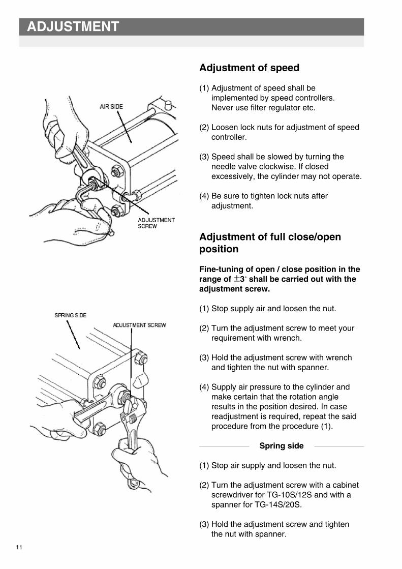
Adjustment of speed
(1) Adjustment of speed shall be implemented by speed controllers. Never use filter regulator etc.
(2) Loosen lock nuts for adjustment of speed controller.
(3) Speed shall be slowed by turning the needle valve clockwise. If closed excessively, the cylinder may not operate.
(4) Be sure to tighten lock nuts after adjustment.
Adjustment of full close/open position
Fine-tuning of open / close position in the range of ±3° shall be carried out with the adjustment screw.
(1) Stop supply air and loosen the nut.
(2) Turn the adjustment screw to meet your requirement with wrench.
(3) Hold the adjustment screw with wrench and tighten the nut with spanner.
(4) Supply air pressure to the cylinder and make certain that the rotation angle results in the position desired. In case readjustment is required, repeat the said procedure from the procedure (1).
Spring side
(1) Stop air supply and loosen the nut.
(2) Turn the adjustment screw with a cabinet screwdriver for TG-10S/12S and with a spanner for TG-14S/20S.
(3) Hold the adjustment screw and tighten the nut with spanner.
ADJUSTMENTSCREW
(4) Check the rotation angle of the shaft by operating the cylinder with air. In case readjustment is required, repeat the said procedure from the procedure (1).
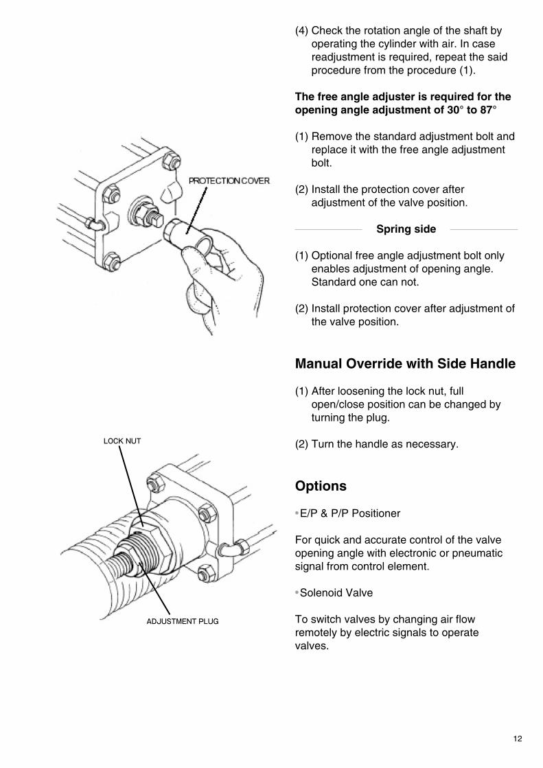
The free angle adjuster is required for the opening angle adjustment of 30° to 87°
(1) Remove the standard adjustment bolt and replace it with the free angle adjustment bolt.
(2) Install the protection cover after adjustment of the valve position.
Spring side
(1) Optional free angle adjustment bolt only enables adjustment of opening angle. Standard one can not.
(2) Install protection cover after adjustment of the valve position.
Manual Override with Side Handle
(1) After loosening the lock nut, full open/close position can be changed by turning the plug.
(2) Turn the handle as necessary.
Options
● E/P & P/P Positioner
For quick and accurate control of the valve opening angle with electronic or pneumatic signal from control element.
● Solenoid Valve
To switch valves by changing air flow remotely by electric signals to operate valves.
12
LOCK NUT
ADJUSTMENT PLUG
ADJUSTMENT
11
Adjustment of speed
(1) Adjustment of speed shall be implemented by speed controllers. Never use filter regulator etc.
(2) Loosen lock nuts for adjustment of speed controller.
(3) Speed shall be slowed by turning the needle valve clockwise. If closed excessively, the cylinder may not operate.
(4) Be sure to tighten lock nuts after adjustment.
Adjustment of full close/open position
Fine-tuning of open / close position in the range of ±3° shall be carried out with the adjustment screw.
(1) Stop supply air and loosen the nut.
(2) Turn the adjustment screw to meet your requirement with wrench.
(3) Hold the adjustment screw with wrench and tighten the nut with spanner.
(4) Supply air pressure to the cylinder and make certain that the rotation angle results in the position desired. In case readjustment is required, repeat the said procedure from the procedure (1).
Spring side
(1) Stop air supply and loosen the nut.
(2) Turn the adjustment screw with a cabinet screwdriver for TG-10S/12S and with a spanner for TG-14S/20S.
(3) Hold the adjustment screw and tighten the nut with spanner.
ADJUSTMENTSCREW
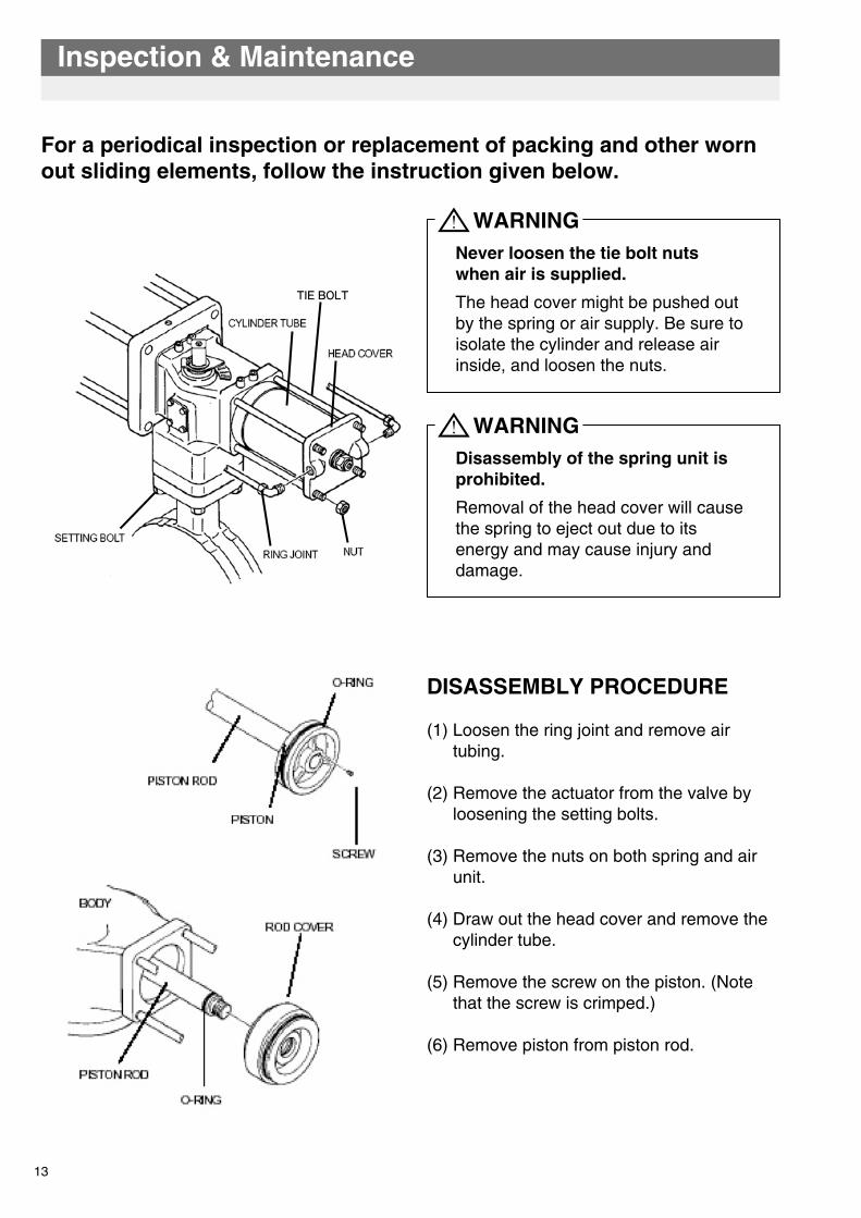
For a periodical inspection or replacement of packing and other worn out sliding elements, follow the instruction given below.
Inspection & Maintenance
WARNING
TIE BOLT
DISASSEMBLY PROCEDURE
(1) Loosen the ring joint and remove air tubing.
(2) Remove the actuator from the valve by loosening the setting bolts.
(3) Remove the nuts on both spring and air unit.
(4) Draw out the head cover and remove the cylinder tube.
(5) Remove the screw on the piston. (Note that the screw is crimped.)
(6) Remove piston from piston rod.
Never loosen the tie bolt nuts when air is supplied.
The head cover might be pushed out by the spring or air supply. Be sure to isolate the cylinder and release air inside, and loosen the nuts.
WARNINGDisassembly of the spring unit is prohibited.
Removal of the head cover will cause the spring to eject out due to its energy and may cause injury and damage.
13
14
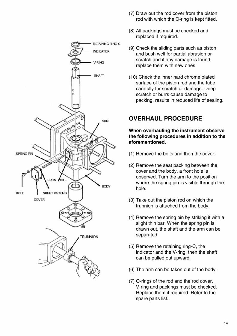
(7) Draw out the rod cover from the piston rod with which the O-ring is kept fitted.
(8) All packings must be checked and replaced if required.
(9) Check the sliding parts such as piston and bush well for partial abrasion or scratch and if any damage is found, replace them with new ones.
(10) Check the inner hard chrome plated surface of the piston rod and the tube carefully for scratch or damage. Deep scratch or burrs cause damage to packing, results in reduced life of sealing.
OVERHAUL PROCEDURE
When overhauling the instrument observe the following procedures in addition to the aforementioned.
(1) Remove the bolts and then the cover.
(2) Remove the seat packing between the cover and the body, a front hole is observed. Turn the arm to the position where the spring pin is visible through the hole.
(3) Take out the piston rod on which the trunnion is attached from the body.
(4) Remove the spring pin by striking it with a slight thin bar. When the spring pin is drawn out, the shaft and the arm can be separated.
(5) Remove the retaining ring-C, the indicator and the V-ring, then the shaft can be pulled out upward.
(6) The arm can be taken out of the body.
(7) O-rings of the rod and the rod cover, V-ring and packings must be checked. Replace them if required. Refer to the spare parts list.
For a periodical inspection or replacement of packing and other worn out sliding elements, follow the instruction given below.
Inspection & Maintenance
WARNING
TIE BOLT
DISASSEMBLY PROCEDURE
(1) Loosen the ring joint and remove air tubing.
(2) Remove the actuator from the valve by loosening the setting bolts.
(3) Remove the nuts on both spring and air unit.
(4) Draw out the head cover and remove the cylinder tube.
(5) Remove the screw on the piston. (Note that the screw is crimped.)
(6) Remove piston from piston rod.
Never loosen the tie bolt nuts when air is supplied.
The head cover might be pushed out by the spring or air supply. Be sure to isolate the cylinder and release air inside, and loosen the nuts.
WARNINGDisassembly of the spring unit is prohibited.
Removal of the head cover will cause the spring to eject out due to its energy and may cause injury and damage.
13
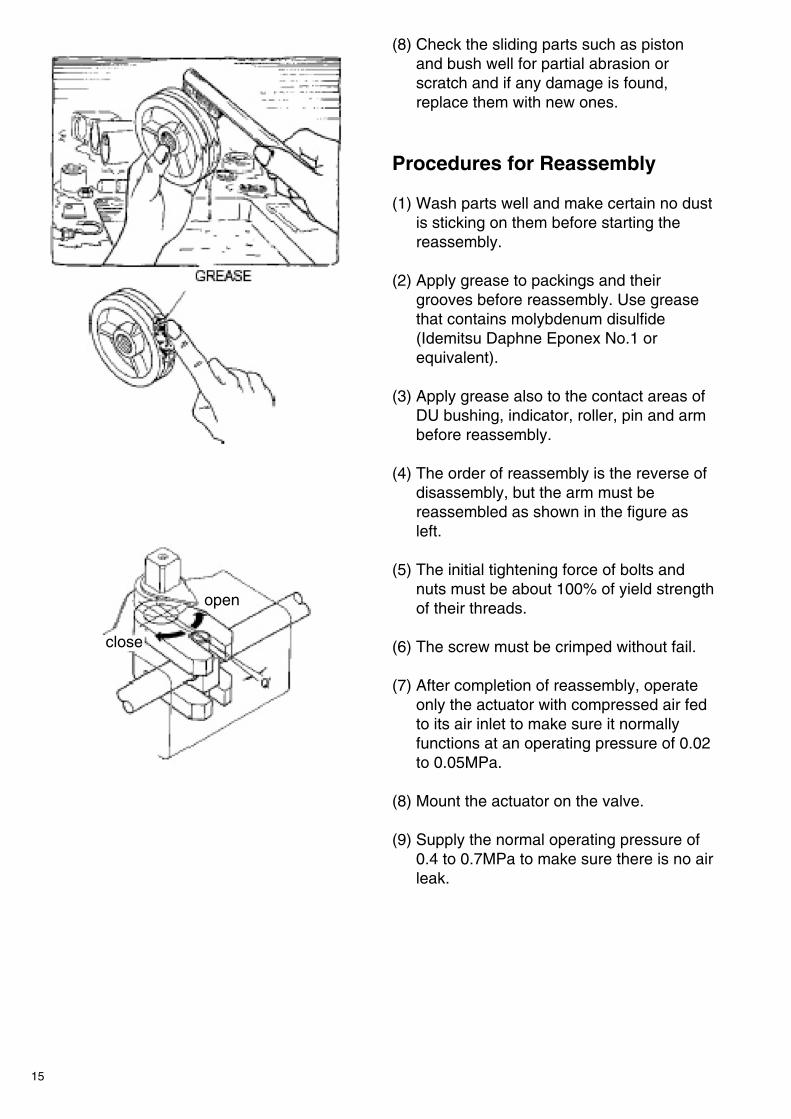
(8) Check the sliding parts such as piston and bush well for partial abrasion or scratch and if any damage is found, replace them with new ones.
Procedures for Reassembly
(1) Wash parts well and make certain no dust is sticking on them before starting the reassembly.
(2) Apply grease to packings and their grooves before reassembly. Use grease that contains molybdenum disulfide (Idemitsu Daphne Eponex No.1 or equivalent).
(3) Apply grease also to the contact areas of DU bushing, indicator, roller, pin and arm before reassembly.
(4) The order of reassembly is the reverse of disassembly, but the arm must be reassembled as shown in the figure as left.
(5) The initial tightening force of bolts and nuts must be about 100% of yield strength of their threads.
(6) The screw must be crimped without fail.
(7) After completion of reassembly, operate only the actuator with compressed air fed to its air inlet to make sure it normally functions at an operating pressure of 0.02 to 0.05MPa.
(8) Mount the actuator on the valve.
(9) Supply the normal operating pressure of 0.4 to 0.7MPa to make sure there is no air leak.
open
close
15
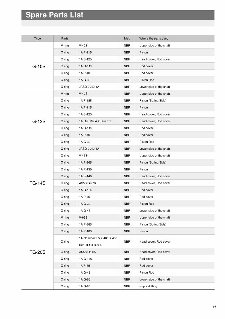
Upper side of the shaft
Piston
Head cover, Rod cover
Rod cover
Rod cover
Piston Rod
Lower side of the shaft
Upper side of the shaft
Piston (Spring Side)
Piston
Head cover, Rod cover
Head cover, Rod cover
Rod cover
Rod cover
Piston Rod
Lower side of the shaft
Upper side of the shaft
Piston (Spring Side)
Piston
Head cover, Rod cover
Head cover, Rod cover
Rod cover
Rod cover
Piston Rod
Lower side of the shaft
Upper side of the shaft
Piston (Spring Side)
Piston
Head cover, Rod cover
Head cover, Rod cover
Rod cover
Rod cover
Piston Rod
Lower side of the shaft
Support Ring
TG-10S
TG-12S
TG-14S
TG-20S
Spare Parts List
16
Type Parts Mat. Where the parts used
V ring
O ring
O ring
O ring
O ring
O ring
O ring
V ring
O ring
O ring
O ring
O ring
O ring
O ring
O ring
O ring
O ring
O ring
O ring
O ring
O ring
O ring
O ring
O ring
O ring
V ring
O ring
O ring
O ring
O ring
O ring
O ring
O ring
O ring
O ring
V-40S
1A P-115
1A S-125
1A G-115
1A P-40
1A G-30
JASO 2040-1A
V-40S
1A P-185
1A P-115
1A S-125
1A Out.199.4 X Dim.3.1
1A G-115
1A P-40
1A G-30
JASO 2040-1A
V-45S
1A P-265
1A P-130
1A S-140
AS568 #276
1A G-135
1A P-40
1A G-30
1A G-45
V-65S
1A P-385
1A P-185
1A Nominal 2.5 X 400 X 405
Dim. 3.1 X 399.4
AS568 #265
1A G-180
1A P-55
1A G-45
1A G-65
1A G-80
NBR
NBR
NBR
NBR
NBR
NBR
NBR
NBR
NBR
NBR
NBR
NBR
NBR
NBR
NBR
NBR
NBR
NBR
NBR
NBR
NBR
NBR
NBR
NBR
NBR
NBR
NBR
NBR
NBR
NBR
NBR
NBR
NBR
NBR
NBR
(8) Check the sliding parts such as piston and bush well for partial abrasion or scratch and if any damage is found, replace them with new ones.
Procedures for Reassembly
(1) Wash parts well and make certain no dust is sticking on them before starting the reassembly.
(2) Apply grease to packings and their grooves before reassembly. Use grease that contains molybdenum disulfide (Idemitsu Daphne Eponex No.1 or equivalent).
(3) Apply grease also to the contact areas of DU bushing, indicator, roller, pin and arm before reassembly.
(4) The order of reassembly is the reverse of disassembly, but the arm must be reassembled as shown in the figure as left.
(5) The initial tightening force of bolts and nuts must be about 100% of yield strength of their threads.
(6) The screw must be crimped without fail.
(7) After completion of reassembly, operate only the actuator with compressed air fed to its air inlet to make sure it normally functions at an operating pressure of 0.02 to 0.05MPa.
(8) Mount the actuator on the valve.
(9) Supply the normal operating pressure of 0.4 to 0.7MPa to make sure there is no air leak.
open
close
15
For your safe and sound usageFor your safe and sound usage
FeaturesFeatures
Standard Specifications
Operation Principle
Air Consumption
Output Torque Curve
Dimensions
Adjustment of Rotation angle & Valve position
Inspection & Maintenance
Spare Parts
Trouble Shooting
INDEX PAGE
Spring Return Pneumatic Cylinder
TG-S 3K/3U
Instruction Manual
1778891011131617
Trouble shooting
TROUBLE CAUSE REMEDY
Air leaks.
Low air pressure.
Air pipes clogged.
Speed controller is shut or throttled.
Air leaking inside cylinder case.
Too high torque required by valve.
Wrong positioning of the stoppers.
Too high torque required by valve.
Wrong adjustment of the speed controller.
O-rings on the piston or between thecase and end cover are worn out.
Increase air supply pressure.
Remove dust from the pipes.
Open the speed controller.
Replace O-rings of the piston.
1) Increase air supply pressure.2) Replace the valve.
Adjust the adjustment screw positioning.
1) Increase air supply pressure.2) Replace the valve.
Readjust the speed controller.
Replace O-rings.
Cylinder cannot open / closevalve.
Valve cannot be fully opened or shut.
The valve opens / closes tooquickly or too slowly.
◎ The specifications are subject to change without notice.Please consult us for the latest specifications.◎ All copy rights reserved.
Cat.No.EG060-④ 2018.11.28-Pn
●Head Office3-11-11 Shinmachi, Nishi-ku, Osaka 550-0013, JapanTelephone: 81-6-6110-2370 Telefax: 81-6-6110-2371 E-mail:[email protected]
Global Sales Operations
No. 317, Kamol Sukosol Building, Unit B, 12th Floor, Silom Road, Silom Sub-district, Bangrak District, Bangkok 10500, ThailandTelephone: +66-(0)-2117-0429 Telefax: +66-(0)-2117-0148 E-mail: [email protected]
TOMOE VALVE (THAILAND) CO., LTD.
15700 International Plaza Drive Suite150, Houston TX, 77032 USATelephone: +1-281-358-7571 Telefax: +1-281-358-7861
TOMOE USA Inc.
Room 1102, Building A, St.NOAH Plaza, No.1759 Jinshajiang Road, Putuo district, Shanghai. 200333, ChinaTelephone: +86-21-52715628 Telefax: +86-21-52653691 E-mail: [email protected]
TOMOE VALVE INDUSTRY (NANTONG) CO., LTD. http://www.tomoe.sh.cn
BlockF2 Latrade Industrial Park, JI. Sei Binti Tanjung Uncang, Batam 29422 IndonesiaTelephone: +62-778-395-466 Telefax: +62-778-396-475 E-mail: [email protected]
PT. TOMOE VALVE BATAM http://www.tomoe-batam.com
No 2, Toh Guan Road East, #02-02, Singapore 608837Telephone: +65-68995060 Telefax: +65-68995061 E-mail: [email protected]
TOMOE VALVE ASIA PACIFIC PTE. LTD. www.tomoe.com.sg
Clearwater Road, Queensway Meadows Industrial Estate,Newport, South Wales NP19 4ST, United KingdomTelephone: 44-1633-636800 Telefax: 44-1633-636801 E-mail:[email protected]
www.tomoeeurope.co.ukTOMOE VALVE LIMITED
www.tomoevalve.com