TRIPLETT Fox Hound 3 · PDF fileFox and Hound 3 Instruction Manual ... vides a visual...
52
1 Fox & The Hound 3 TRIPLETT Instruction Manual
Transcript of TRIPLETT Fox Hound 3 · PDF fileFox and Hound 3 Instruction Manual ... vides a visual...

1
Fox &The
Hound 3
TRIPLETT
Instruction Manual

2
Fox and Hound 3 Instruction Manual
Table of Contents1. Introduction . . . . . . . . . . . . . . . . . . . . . . . . . . . . . 2 - 32. FOX Features . . . . . . . . . . . . . . . . . . . . . . . . . . . . . . . 33. HOUND 3 Features . . . . . . . . . . . . . . . . . . . . . . . . . . . 44. Safety Warnings and Cautions . . . . . . . . . . . . . . . . 5 - 65. Specifications . . . . . . . . . . . . . . . . . . . . . . . . . . . . 7 - 106. Control Locations . . . . . . . . . . . . . . . . . . . . . . . . . 11 - 127. Getting Started . . . . . . . . . . . . . . . . . . . . . . . . . . . 13 - 208. Operating Instructions: Detailed Information . . . 20- 499. Accessories and Replacement Parts . . . . . . . . . . . . . . . 4910. Warranty . . . . . . . . . . . . . . . . . . . . . . . . . . . . 50 & 51
1: IntroductionThe FOX and HOUND 3 wire tracing kit consists of a classicFOX Tone Generator (Toner) and a newly designed HOUND 3Inductive Amplifier (Probe). The FOX is a battery operatedhandheld lightweight multi-function Toner that can generate3 different tones (Hi, Lo, and Warble), perform some basictelephone line tests (loop mA and line polarity), and pro-vides a visual continuity test. The HOUND 3 is a battery op-erated handheld lightweight Probe, with a thumbwheel Sen-sitivity control and Signal Strength indicator LED. It improveson previous designs (the HOUND and HOUND 2) with built-in LED illuminators, a bandpass filter, an earphone jack, andan easy access battery cover. An included convenient carry-ing case (with belt loop attachment) provides ease of useand protective storage for the FOX and HOUND 3.
84-863
3
When used together, the FOX and HOUND 3 aids in identify-ing, locating, and tracing wires, cables, and other conduc-tors. When the FOX is used to apply a “tone” to a wire, theHOUND 3 can usually locate the wire inside of, or behindelectrically non-conductive surfaces (plastic, wood, drywall,etc), up to 12 inches away. The HOUND 3 does not have tocontact a wire to identify it . . . i.e. no stripping needed.FOXs and HOUNDs have been used in the telephone, electri-cal, security, sound reinforcement, video, automotive, andboating industries, to name a few.
2: Key Features of the FOX• Generates 3 distinct tones usable for wire tracing• Performs a variety of tests on telephone lines• Line powered in Tone Mode• LED Indicator for continuity• Supplies “Talk Power” to allow communicating between handsets (talksets) or powering a telephone• Alligator clips and modular plug allow for connection to stripped wires, terminal panels, or a standard modular jack (single line)• Powered by a standard 9V battery (not included)• One Year Warranty
4
3: Key Features of the HOUND 3• New Headlights to help light your way in dark areas and reduce florescent light noise!• Streamlined Design allows for better access in hard-to-reach areas• New Shielded Design to suppress “Feedback Squeal”• Bandpass Filter to suppress 60Hz and Hi Frequency Noise• Earphone Jack for use in quiet or noisy environments.• Improved Sensitivity and Loudness• Includes New Conductive Plastic Duck-Bill Tip for Safer, Easier Penetration in cable bundles - Metal tip also included• Easy Access Battery Door• Adjustable volume / sensitivity control• LED gets brighter as the signal gets stronger - LED indication even works when Earphones are used!• Contains a hi-gain, hi-impedance amplifier• Capable of identifying the Fox’s tone up to 12 inches away• Rugged, moisture resistant, mylar cone speaker• Powered by a standard 9V battery (not included)• One Year Warranty
5
4: Safety Warnings and Cautions
4.1Do not connect FOX or HOUND 3 to any source of AC power.AC voltages above 30 volts can be dangerous, and may re-sult in user injury. The FOX and HOUND 3 is not intended totrace live AC power lines. The FOX will be damaged if con-nected to a live AC power line.
4.2Use care when using the HOUND 3 to probe any wire or cable.An unexpected dangerous voltage may be present, whichmay result in injury to the user.
4.3Potentials applied to the HOUND 3’s probe may appear,greatly reduced, at the earphone jack. This could pose a shockhazard to the user, if for example, the probe is brought incontact with a high voltage potential.
4.4The HOUND 3’s metal probe can accidentally short out a cir-cuit that is being tested. Use care when testing live circuitry,or an accidental short may result in equipment damage oruser injury.
6
4.5Use caution when working with telephone lines. They cansupport dangerous voltages. 50VDC is often present, and100VAC may be present during ringing. Additionally, tele-phone lines may support dangerous levels of common modevoltages. In some circumstances, user injury may result.
4.6Use caution when working with any long unconnected wireor cable. Under some conditions, unconnected wires may“float up” to dangerous potentials, and touching them mayresult in user injury.
4.7Use care when connecting the FOX to any wire or cable. Anunexpected dangerous voltage may be present, which mayresult in injury to the user.
4.8Potentials applied to any connection of the FOX may appearon other FOX connections. For example, a potential appliedto the RJ-11 plug may appear on the alligator clips. Thiscould pose a shock hazard to the user, if for example, a tele-phone cable with 120VAC on it is connected to the FOX . The120VAC may appear on the alligator clips, and shock theuser.
7
5: Specifications
5.1: FOX Specifications
5.1.1: Telephone Loop mA and Line Polarity Test:Indication: Red LED lights to indicate presence of Loop mA in correct polarityLoad: Approx. 13mA at 50VDC (usually less than off-hook recognition current)
5.1.2: Visual Ring Indication:Indication: Red LED flashes to indicate ringing
5.1.3: Tracer Tone (with fresh battery):Waveform:Square Wave or Differentiated Square Wave Level: Approx. 8Vpp (+14dBu, 600 Ohm) into an open circuit (un-terminated cable or telephone line) Approx. 5Vpp (differentiated) +2dBm into a 600 Ohm load (terminated telephone line)Frequencies (3 types): LO - approx. 800Hz HI - approx 1000Hz WARBLE - alternates between LO and HI
5.1.4: Connections:RJ-11 Plug for connection to telephone linesColor Coded Alligator Clips for connection to stripped wiresor terminals

8
5.1.5: Visual Continuity:LED lights when continuity is establishedOpen Circuit Voltage: 10v max.Test Current: 35mA max
5.1.6: Talk Power:Open Circuit Voltage: 10v max.Current (Short Circuit): 35mA maxCurrent with 1K Loop: Typically 6mA with new 9v battery
5.1.7: Protection:Will withstand 56V with 400 Ohms series resistance appliedacross outputs. Will withstand 175V peak with 100 Ohmsseries resistance, superimposed on 56V, for 100mS (stan-dard telco “ring” signal). DO NOT CONNECT TO LIVE ACPOWER LINES.
5.1.8: Power:Battery: Standard 9v Alkaline Battery
(NEDA 1604A, Eveready 522)Battery Life: Approx 500 hours continuous in
Tone Generator modeTelephone Line Powered Operation:
Tone Generator operates without 9v batteryinstalled. Operates from standard telephoneline (46 to 53v, 400 to 1800 Ohms) innormal or reverse polarity.
9
5.1.9: NiCad Charging Current: Approx. 9mA
5.1.10: Dimensions: Case: 3.7"H x 2.4"W x 1.1"T
(93mm x 61mm x 28mm) Leads: Alligator Clips: Typically 11 inches long
RJ-11: Typically 9 inches long
5.1.11: Weight:Less than 7 ounces including battery
5.2: HOUND 3 Specifications5.2.1: AmplifierHigh impedance bootstrapped FET input for high gain andsensitivity. Incorporates a bandpass filter to improve sensi-tivity to FOX signals while suppressing 60Hz.5.2.2: SensitivityDetects FOX’s tone up to 12 inches away.
5.2.3: Speaker1-1/2" mylar coned speaker with high strength alnico mag-net is rugged and moisture resistant.
5.2.4: Probes (2 provided)a) Solid aluminum conical probe for low resistance contacttestingb) Conductive Plastic duckbill probe with metal threads forsensitive non-shorting testing.
10
5.2.5: Earphone JackAccepts standard 1/8" (3.5mm) mini phone plug, either monoor stereo. For use with electromagnetic (dynamic) earphonesfrom 8 Ohms to 2000 Ohms. Automatically mutes loud-speaker when earphone is used. An earphone with a shieldedcable is suggested to reduce the possibility of feedback fromthe cable to the probe tip.
5.2.6: Signal Strength IndicatorBright red LED signal strength indicator maintains sensitiv-ity, even when the earphone is used.
5.2.7: PowerA standard 9 volt alkaline battery (NEDA 1604A, Eveready522) provides power for all circuitry. The battery is acces-sible by removing a convenient snap-on door (no toolsrequired). The HOUND 3 is protected against the accidentalreversal of the battery polarity.
5.2.8: Illumination2 efficient bright white LEDs powered from separate currentsources provide constant illumination until battery is mostlydepleted (about 6 volts).
5.2.9: Size1-7/8" dia at speaker, 1-3/8" dia at body, 8-1/4" long withmetal probe, 9-1/4" with conductive plastic probe.
5.2.10: WeightLess than 8 ounces including battery
11
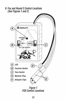
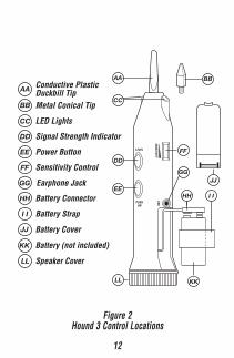
6: Fox and Hound 3 Control Locations (See Figures 1 and 2)
A LED
B Function Switch
C Tone Switch
D Modular Plug
E Alligator Clips
B
TRIPLETT
TONE HI
LO
CONTINUITYTALK
WARBLE
OFF / LINE POLARITYC
D
A
E
Figure 1FOX Control Locations
12
AA Conductive PlasticDuckbill Tip
BB Metal Conical Tip
CC LED Lights
DD Signal Strength Indicator
EE Power Button
FF Sensitivity Control
GG Earphone Jack
HH Battery Connector
I I Battery Strap
JJ Battery Cover
KK Battery (not included)
LL Speaker Cover
AA BB
CC
DD
EE
FF
GG
HH I I
JJ
KKLL
Figure 2Hound 3 Control Locations

13
7: Getting Started
7.1: The FOX
7.1.2: Installing a standard 9 volt battery in the FOXRemove the screw on the back of the case. Remove thecase front. Install / replace the battery. Reassemble thecase.
7.1.3: Using a rechargeable battery in the FOXThe FOX can recharge a 9 volt Nicad battery by using tele-phone Loop Current (CO power). To use this feature, simplyreplace the standard 9 volt battery with a 9 volt Nicad bat-tery. To charge the Nicad, set the FOX to OFF/LINE POLAR-ITY, and connect the alligator clips to the line in ReversedPolarity (Red to positive and Green to negative). Connect-ing to the line in Normal Polarity WILL NOT CHARGE thebattery. Approximately 16 hours is required to fully chargea typical Nicad battery (refer to battery manufacturer specs).
Emergency Fast Charge:The FOX’s circuitry incorporates a fast charge mode. Thismode is not recommended for casual use because it exceedsthe battery’s nominal charge current and will shorten thebattery’s life. Charging current could be as high as 90 mA.
To use this feature, set the FOX to CONTINUITY / TALK andconnect the alligator clips to a powered line in ReversedPolarity (Red to positive and Green to negative). DO NOTcharge the battery for more than 30 minutes. Irreversible
14
shortening of the battery’s life may result. DO NOT connectto the line in Normal Polarity. Damage to the battery mayresult.
7.1.4: Testing the Battery in the FOXAfter installing the battery, a basic test can be performed toverify that the battery is powering the FOX. Set FunctionSwitch (B) to its CONTINUITY / TALK position. Whiles ob-serving LED (A), short alligator clips (E) together. If the bat-tery is OK, the LED will light. A bright LED indicates a freshbattery . . . a dim LED indicates a weak battery . . . no lightfrom the LED indicates a dead battery.
Helpful Hint:Although a weak battery in the FOX may not provide adequatepower to operate several talksets, the TONE feature oftenworks with a weak battery, and the POLARITY test does notrequire a battery to work.
7.2: The HOUND 3
7.2.1: Installing a 9 volt battery in the HOUND 3Remove Battery Cover (JJ) by pressing the release tab to-wards probe end of the case. Remove Battery Connector (HH)and Battery Strap (II). Snap Connector to 9 volt battery andslide Strap over battery. Position Strap so that the finger tabis on the side of the battery. Insert battery into HOUND 3case, placing bottom of battery against foam, and compress-ing the foam while completing the battery insertion. Leadwires should be behind battery and “dressed” to allow bat-

15
tery to be fully inserted. The finger tab on the Strap shouldbe sticking out of the Battery Compartment. This tab is usedto remove the battery. Fold the tab over, and secure the Bat-tery Cover to the case by inserting the end near the Ear-phone Jack (GG) first, and snapping the opposite end of theCover to the case.
7.2.2: Testing the battery in the HOUND 3The battery in the HOUND 3 will not last as long as the bat-tery in the FOX. The LED Lights (CC) can be used as a roughindication of battery charge. With a fresh battery, the Lightswill be bright, and the HOUND 3’s Speaker (LL) will producea loud, strong, signal from the FOX. As the battery is drained,the signal from the FOX will not sound as loud in the HOUND3’s Speaker. When the Lights begin to dim, the battery shouldbe replaced.
7.3: A Few Basic TestsTurn on the FOX by sliding the Function Switch to the TONEposition. Set Tone Switch (C) to the WARBLE position. Thisis the position that most users prefer for wire location andtracing.
Rotate the HOUND’s Sensitivity Control (FF) to its mid-posi-tion. Turn on HOUND 3 by pressing and holding the PowerButton (EE). Bring the HOUND 3’s probe (AA or BB) near theFOX’s alligator clips. The warbling signal from the FOX shouldbe heard in the HOUND 3’s Speaker (LL). Adjust the Sensi-tivity Control for the desired loudness. Move the probe ofthe HOUND 3 closer to and farther away from the FOX’s alli-
16
gator clips. Notice how the loudness of the warble soundincreases, and how the brightness of the Signal StrengthIndicator (DD) increases as the probe approaches the alliga-tor clips.
In general, the HOUND 3 is used by bringing it into proxim-ity with the wire/cable that the FOX is connected to, listeningfor the TONE signal from the FOX, and moving the HOUND 3in such a manner as to increase the loudness of the TONEsignal from the HOUND 3’s speaker . . . i.e. searching forthe loudest TONE signal.
The HOUND 3’s Sensitivity Control is usually set to maxi-mum when tracing wires through walls and ceilings, and isset to a lower setting when in close proximity to the signalcarrying wires. In situations where there is a lot of acousticnoise, observing the brightness of the LED, or using ear-phones, may prove more useful than attempting to hear thesignal from the speaker.
Helpful Hints:It is normal to hear a humming or buzzing noise comingfrom the HOUND 3’s speaker when it is in an area with fluo-rescent lights, neon signs, transformers, etc. In fact, an easytest to verify the HOUND’s is working is to move it toward anoperating fluorescent light and note that the buzzing soundgets louder, and the brightness of the LED increases.
If the buzzing sounds from fluorescent lights interfere withtracing/locating wires, the user may consider turning the fluo-
17
rescent lights off and using the HOUND 3’s built in lights(which do not produce any noise).
7.4: Choosing a Probe TipThe HOUND 3 is supplied with 2 Probe Tips. The metal coni-cal tip provides the strongest signal in most cases, becauseit can make a metallic electrical connection with a wire car-rying the FOX signal. In some cases, the metal tip can be asafety hazard . . . because it might short out a live circuitthat the user is “probing”. The metal tip is rather short andlarge in diameter, making it difficult to insert into wire bundleswhile searching for the target wire.
The conductive plastic duckbill tip will not short out mostelectrical circuits. The conductivity of the probe is very lowcompared to the metal tip. Additionally, the slender duckbillshape allows the tip to be inserted into wire bundles whilesearching for the target wire. Most users prefer this tip, al-though it is not quite a rugged as the solid metal tip.
7.5: Earphone JackThe HOUND 3 has a Jack (GG) for connecting external Ear-phones (Headphones). When using the external earphones,the HOUND’s internal speaker is turned off. The earphonesare usually used when there is so much ambient noise thatthe speaker cannot be heard, or when the sound of thespeaker may be annoying to others in the vicinity.
18
Helpful Hint:Almost any type of earphones whose plug will fit into theEarphone Jack will work. Some types will work better thanothers. An earphone with shielded wires is recommended.Use of earphones with unshielded wires may cause a squeal-ing sound to be heard.
7.6: How it worksThe HOUND 3 works by capacitively sensing the electrostaticfield radiated by wires carrying a signal from the FOX. Thegreater the radiated field, the better the HOUND 3’s ability tolocate a wire. Anything that reduces the intensity of the fieldwill impair the HOUND 3’s effectiveness in locating a wire.
In general, several things affect field intensity . . . shielding,signal (tone) amplitude on the wire, and wire dress. In in-stances where a system is shielded (shielded wires, metaljunction boxes, metal conduit, etc.), the effectiveness of theHOUND 3 is impaired. In multi-wire cables, grounded wires,or wires connected to low impedance circuits, adjacent tothe target wire can act as shields, reducing the HOUND 3’sability to sense properly. Spreading the wires apart will re-duce the shielding effect and allow the HOUND 3 to workbetter. Defects in a cable or wires, such as shorts or opens,will reduce the signal amplitude and hence the HOUND 3’sability to locate the target wire. Terminating a wire or line ina low impedance also reduces signal amplitude and theHOUND 3’s locating ability. It is also possible for wire posi-tion to cause nullification of the field.
19
If the target wire is connected to other wires and circuits,for example, to switches, lights, relays, transformers, etc.,the FOX TONE will pass through these devices and out ontoother wires connected to these devices . . . making tracingof the target wire very difficult, if not impossible.
In general, the FOX and HOUND 3 cannot be use to tracewires buried underground or in concrete. This is becausethe moisture content of the earth or of concrete allows thesurface to be electrically conductive, causing it to act as ashield around the buried wire.
Wet drywall, wet cinder block walls, or any wet wall surfacewill also shield the FOX signal, preventing the HOUND 3 fromdetecting its presence.
The actual wire being wet can shield the signal. The wire canbe wet internally, shielding the signal. This phenomena hasbeen observed in “Romex” electrical wire. The internal pa-per separator can get wet from exposure to the weather. Theexterior surface of the Romex can be dry, but because theinternal paper separator is wet, it shields the tracer signal.
Extremely high humidity will damp (collapse) the electro-static field, reducing the effectiveness of the HOUND 3 infinding the FOX signal. Condensing atmospheres may evencause the products to malfunction until they dry out.
The HOUND 3 will not trace wires through a metal conduit.It can, however, identify the wires after they exit from theconduit.
20
General Rules for Effective Tracing:…. Do what works best. Try both LINE/GROUND and LINE/LINE tracing (see following text).…. Separate wires when possible.…. Move wires away from shielding when possible.…. Un-terminate wire if necessary.…. Turn off noise sources to reduce buzzing
OPERATING INSTRUCTIONS:8: Detailed Product Information
8.1: FOX Details (Refer to Figure 1)The Function Switch (B) sets the basic operating mode. The3 positions each have several testing functions associatedwith them. The follow text describes these test features indetail. The Tone Switch (C) selects a HI, LO, or WARBLEtone. The alligator clips (E) and the modular plug (D) allowthe FOX to be connected to a variety of different wires andcables. The LED (A) provides indication of line polarity andcontinuity.
8.1.1: Telephone Loop Current Powering: Line PoweringOn telephone lines, the FOX’s TONE mode can be poweredfrom “Loop Current”. Loop Current is provided by the Tele-phone Company (the Central Office…. CO) to power the typi-cal telephone. When powered by Loop Current, the FOX’sinternal 9 volt battery is not needed. To use this feature,simply connect the FOX’s alligator clips (E) or modular plug(D) to the powered line on which the tone is to be sent. TheFOX will not “seize” or “capture” the line of most phone sys-tems.
21
Helpful Hint:Although the FOX does not require a battery when generat-ing a tone when Loop Current is present, if a battery is in theFOX, it will be used as part of the FOX’s power source. Dueto the FOX’s internal circuitry, less battery power is used ifthe FOX is connected to the line in Reverse Polarity, i.e. Tipto Negative, Ring to Positive. Therefore, for greatest batterylife, connect to a powered line in Reverse Polarity.
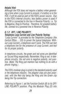
8.1.2: OFF / LINE POLARITY:Telephone Loop Current and Line Polarity Testing:“Loop Current” is provided by the Telephone Company (theCentral Office…. CO) to power the typical telephone. With-out Loop Current, a telephone won’t work. The FOX can testa telephone line for the presence of Loop Current, and testfor its proper polarity.
In telephone circuits, the green and red wires are identifiedas Tip and Ring respectively. Remember, Ring is red. In tele-phone circuitry, the red wire is negative polarity, not posi-tive. (Note: The Ring just mention has nothing to do with aphone ringing.) .
The FOX’s modular plug is wired in the standard polarity usedin the telephone industry. The alligator clips are also polar-ized, with the Red clip being the Ring and the Green clipbeing the Tip connection.
Referring to Figure 1, set the Function Switch (B) to its OFF/LINE POLARITY position. Plug the Modular Plug (D) into
22
the modular jack to be tested, or connect the Alligator Clips(E) to the line to be tested (Do not use the Modular Plug andthe Alligator Clips simultaneously). If Loop mA is present,and in the correct polarity, the FOX’s CONTINUITY/TALK LED(A) will light. If the polarity is incorrect, or Loop mA is notpresent, the LED will not light.
Helpful Hints:If using the Alligator Clips, and the LED does not light, tryreversing the positions of the clips. If the LED then lights,Loop mA is present, and in the polarity indicated by the clips.
Although the LED will light on a BUSY (off-hook) line whenperforming the test, the LED will light much more brightly ifthe line is CLEAR (on-hook).
The FOX also indicates line polarity, when the line is CLEAR,in the TONE Mode. However, the line polarity LED may ormay not light in the TONE Mode, on a BUSY line.
On analog phone lines, reversed polarity seldom causes aproblem. Many modular cords and couplers reverse the po-larity of the phone line passing through them.
8.1.2.1: Ringing Current:The FOX will signal the presence of ringing current by flash-ing its LED. This indication is obtainable in either the OFF/LINE POLARITY or TONE mode. Depending on the phonesystem, the LED may indicate ringing current in either Nor-mal or Reversed Polarity. To perform this test, simply con-

23
nect the alligator clips or the modular plug to the line to betested. The FOX will not seize the line on most phone sys-tems.
8.1.3: CONTINUITY / TALKWhen the Function Switch is set to the CONTINUITY / TALKposition, the FOX can perform basic Continuity tests, or sup-ply Talk Power to several “talksets”.
8.1.3.1: Continuity Testing:The FOX can be used as a visual continuity indicator. Set theFOX’s Function Switch to CONTINUITY / TALK. When theFOX’s red and green alligator clips are touched together, theLED will light, indicating continuity. To check continuity,connect the red and green alligator clips to the circuit undertest and observe the LED. Continuity from zero to 10K ohmswill be indicated by the brightness of the LED. The LED willbe bright at low resistances and dim at high resistances.
Do not attempt to measure continuity on a powered line.
8.1.3.2: Talk Power:The FOX will supply power to operate handsets. This fea-ture is particularly useful when two installers are working atterminal panels that have at least one identified pair con-nected between them, but are not yet connected to the CObattery. The FOX allows the installers to communicate us-ing their handsets. Set the FOX’s Function Switch to Conti-nuity / TALK and connect the handsets as shown in Figure 3.The FOX’s LED will light when supplying Talk Power.

24
NOTE: Some handsets may not operate properly at the powerlevel supplied by the FOX.
TRIPLETT
TONE HI
LO
CONTINUITYTALK
WARBLE
OFF / LINE POLARITY
TALK SETTALK SET
WIRE PAIR
Figure 3FOX supplying “Talk Power”
25
8.1.4: TONE: Wire Tracing, Identification, & Open FaultsThe uses of the FOX Tone mode can usually be divided intothree categories . . . tracing, identification, and locating openfaults.
8.1.4.1: General Wire Tracing Information:The FOX and HOUND 3 will not trace “live” AC or DC powerwires.
The only type of “live” circuit that the FOX and HOUND 3 willtrace is a telephone circuit.
The FOX’s tracer tone will not penetrate electrically conduc-tive materials . . . like any kind of metal or wet earth. Thismeans that the HOUND 3 cannot pickup the tone if the targetwire is in a metal conduit or is underground. The HOUND 3will pickup the tone at locations where the target wire emergesfrom the conduit or the earth.
The FOX’s tracer tone will penetrate wood frame walls andceilings, and plaster and drywall. Under good conditions, aHOUND 3 can pickup the tone from a foot or more awayfrom the target wire.
The FOX’s tracer tone will pass through any electrical cir-cuitry connected to the target wire(s). Hence, to identify aspecific wire, it will be necessary to disconnect all loads andcircuitry from the wire. This includes switches, capacitors,resistors, coils, transformers, lights, motors, etc.
26
The FOX’s tracer tone can be shorted out by any loads onthe target wire. All loads must be disconnected from the tar-get wire.
Crosstalk may occur in multiwire cables, in wires bundledtogether into a harness, or in wires that run parallel to eachother for long distances . . . making identification of the tar-get pair difficult.
Crosstalk is the bleeding of the tracer tone from the targetwire onto adjacent wires. A tracer tone applied to a targetwire or wires may crosstalk onto adjacent wires. Some wires/cables are constructed to reduce the crosstalk, but other wire/cables crosstalk readily. So much crosstalk can occur thatthe tracer tone on the adjacent wires can be almost as largeas the original tone on the target wire. This can make it dif-ficult to identify the target wire with the HOUND 3. A methodof trying to determine if the tone being received is the origi-nal tone, or is crosstalk, is to short out the wires with thetone at the location where the HOUND 3 is being used. TheFOX supports the Remote Tone Kill method. Shorting theoutput of the FOX, anywhere along the length of the targetwire, kills the tone everywhere along the wire. If shortingthe wires only reduces the tone’s level, but does not com-pletely kill it, then the shorted wires have crosstalk on them,and are not the target wires. If shorting the wires completelykills the tone, then its likely that the wires are the target wires.Unfortunately, this test is not 100% effective.
27
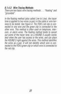
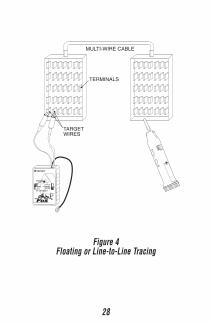
8.1.4.2: Wire Tracing Methods:There are two basic wire tracing methods . . . “floating” and“grounded”.
In the floating method (also called Line to Line), the tracertone is applied to two wires (a pair) in the cable or wire har-ness to be tested. See Figure 4. The FOX’s red clip is con-nected to one wire and the green clip is connected to theother wire. This method is often used on telephone, inter-com, or alarm wires. The floating method tends to cancelout some of the tracer tone, so a HOUND 3 usually worksbest when the user has access to the wires, and can placethe HOUND 3 right against the wires. This method identifiesthe wires as a pair. It will not identify which wire is con-nected to the FOX’s green clip or which wire is connected tothe red clip.
28
TRIPLETT
TONE HI
LO
CONTINUITYTALK
WARBLE
OFF / LINE POLARITY
MULTI-WIRE CABLE
TERMINALS
TARGETWIRES
Figure 4Floating or Line-to-Line Tracing
29
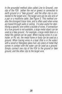
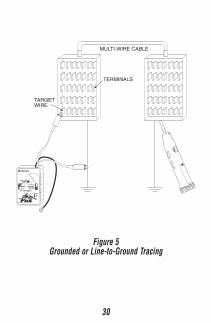
In the grounded method (also called Line to Ground), oneclip of the FOX (either the red or green) is connected toearth ground or a “fake ground”, and the other clip is con-nected to the target wire. The target wire can be one wire ofa pair or a multiwire cable. See Figure 5. This method cre-ates the strongest tracer tone, and is often used when wiresare traced through walls or ceiling. It is also useful for iden-tifying a specific wire within a bundle of wires. If connectionto a true ground is not available, a large metal object can beused as a fake ground. For example, a large metal desk or ametal file cabinet can be used. When tracing wires in a car,trailer, or RV, etc. the metal frame or body can be used as aground. When tracing wires in a boat (that is in the water)with a wood or fiberglass glass hull, any piece of metal thatcomes in contact with the water can be used as a ground.Simply connect one clip of the FOX to the ground or fakeground, and the other clip to the target wire.
30
TRIPLETT
TONE HI
LO
CONTINUITYTALK
WARBLE
OFF / LINE POLARITY
MULTI-WIRE CABLE
TERMINALS
TARGETWIRE
Figure 5Grounded or Line-to-Ground Tracing

31
Helpful Hints:Extension pieces of wire, or long clip leads, can be used toconnect the FOX to a ground or fake ground. The extensionwire can be hundreds of feet long if necessary.
To test a fake ground to see if it can be used for wire tracing,connect one clip from the FOX to the candidate object (like ametal desk) and the other clip of the FOX to the target wire.Hold a HOUND 3 near the object. A “good” fake ground willnot radiate much tracer tone. The tracer tone should be muchstronger on the FOX’s other clip. If it is not, the target wiremay be shorted to ground, or the fake ground may not beadequate. Generally, the larger the object used as the fakeground, the better it works.
If the target wire is somehow connected to ground, this willgreatly reduce or kill the tracer tone.
8.1.4.3: Telephone wires:The floating method is usually used to locate a pair of wiresin a telephone junction block. If the wires are already termi-nated into a modular telephone jack, simply plug the FOXinto the jack. This method works with the phone line con-nected or disconnected from the wires going to the telephonecompany. A stronger trace is usually obtained if the wiresare not connected to the telephone company.
If the wires are not connected to the telephone company,the grounded method can be used to trace telephone wiresthrough a wall or ceiling. Use the green and red clips to con-
32
nect to the phone line and ground.
To identify the wires, if using the floating method, momen-tarily short the suspected wires together while listening tothe FOX signal with the HOUND 3. If the FOX signal is com-pletely killed (not heard on the HOUND 3), the selected pairis probably the target pair. If the signal is not completelykilled, the wrong pair has been selected, or there is an openfault in the pair, and crosstalk is being picked up from theother wires.
To identify the wires, if using the grounded method, mo-mentarily short the suspected wire to ground while listeningto the FOX signal with the HOUND 3. If the FOX signal iscompletely killed (no heard any more on the HOUND 3), theselected wire is probably the target wire. If the signal is notcompletely killed, the wrong wire has been selected, or thereis an open fault in the wire, and crosstalk is being picked upfrom the other wires. (This will not work if a fake ground isbeing used. An actual ground is required to perform thistest).
An “Open Fault” may involve either one or both wires of atelephone wire pair. Finding the open will only work if thereare no other faults (like a short to earth ground) in the pair.
If the pair is “live”, disconnect the pair from the incomingtelephone line before trying to locate the open. Short thewires together at the far end and connect the shorted wiresto a good earth ground (a fake ground may not work well).
33
At the other end of the wires, connect one of the clips of theFOX to a good earth ground. Experimentally connect the otherclip of the FOX to one wire and then the other, while listen-ing to the tracer tone on this clip with a HOUND 3. If thelevel of the tracer tone drops significantly when the clip isconnected to one of the wires, this wire is probably OK andthe other wire is open. That is, the open wire is the one thatdoesn’t drop the level of the tracer tone. If neither wire dropsthe level of the tracer tone, they are probably both open (ora good ground has not been used).
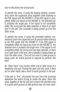
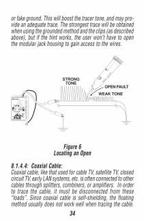
Leave the clip connected to the wire or wires that do not“load down” the tracer tone. See Figure 6. Using a HOUND3, follow the path of the wires by finding the strongest sig-nal. An abrupt drop in the tracer tone level will occur at thepoint of the open. Keep in mind, however, if tracing unseenwires in the wall or ceiling, that the wires may pass behind ametal object (like a furnace duct) that prevents the HOUND3 from picking up the tracer signal, or the wires may divergefrom the path of the receiver. Before assuming that the openhas been located, try finding the signal nearby or in an adja-cent attached wall or ceiling. Also keep in mind that it maynot be possible to find the open in all situations, because ofthe number of variables involved.
Helpful Hints:If attempting to trace a telephone wire terminated in a modu-lar jack, but not connected to the telephone company, througha wall or ceiling, insert the FOX’s modular plug into the jack,and then connect either the red or green clip lead to a ground
34
or fake ground. This will boost the tracer tone, and may pro-vide an adequate trace. The strongest trace will be obtainedwhen using the grounded method and the clips (as describedabove), but if the hint works, the user won’t have to openthe modular jack housing to gain access to the wires.
TRIPLETT
TONE HI
LO
CONTINUITYTALK
WARBLE
OFF / LINE POLARITY
STRONGTONE
OPEN FAULT
WEAK TONE
Figure 6Locating an Open
8.1.4.4: Coaxial Cable:Coaxial cable, like that used for cable TV, satellite TV, closedcircuit TV, early LAN systems, etc. is often connected to othercables through splitters, combiners, or amplifiers. In orderto trace the cable, it must be disconnected from these“loads”. Since coaxial cable is self-shielding, the floatingmethod usually does not work well when tracing the cable.
35
It can be done, but the HOUND 3 must be held very close tothe end of the cable to pick up any signal. To apply a floatingsignal to a coax, connect one clip of the FOX to the centerconductor of the coax, and the other clip to the shield of thecoax.
The grounded method often works better for tracing coaxialcables. Connect one clip of the FOX to a ground or fakeground, and the other clip to the shield of the coax. Thismethod will cause the coax to radiate enough tracer tone totrace the coax thru drywall.
To identify the coax, if using the floating method, momen-tarily short the shield and center conductor together whilelistening to the FOX signal with the HOUND 3. If the FOXsignal is completely killed (not heard on the HOUND 3), theselected coax is probably the target coax. If the signal is notcompletely killed, the wrong coax has been selected, or thereis an open fault in the coax, and crosstalk is being picked upfrom the other wires.
To identify the coax, if using the grounded method, momen-tarily short the shield to ground while listening to the FOXsignal with the HOUND 3. If the FOX signal is completelykilled (not heard on the HOUND 3), the selected coax is prob-ably the target coax. If the signal is not completely killed,the wrong coax has been selected, or there is an open faultin the coax, and crosstalk is being picked up from the othercoaxes. (This will not work if a fake ground is being used.An actual ground is required to perform this test).
36
It is not unusual for the loose turn-able part of a coaxialconnector to have poor electrical contact to the cable shielduntil it is screwed on to its mating connector. Consider thiswhen making connection to a coax.Because of the way that coax is constructed, it is not pos-sible to find an open in the center conductor. It is possible tofind an open in the shield, if the shield is not shorted to thecenter conductor or ground. Connect the center conductorof the coax to earth ground. Connect the shield and centerconductor at the far end of the coax to earth ground. Con-nect one clip of the FOX to an earth ground. Experimentallyconnect the other clip of the FOX to the shield of the coax,while listening to the tracer tone on this clip with a HOUND3. If the level of the tracer tone drops significantly when theclip is connected to the shield, the shield is probablygrounded and can’t be traced to the open.If the level of the tracer tone doesn’t drop much, leave theclip connected to shield. Using a HOUND 3, follow the pathof the coax by finding the strongest signal. An abrupt dropin the tracer tone level will occur at the point of the open.Keep in mind, however, if tracing unseen coaxes in the wallor ceiling, that the coaxes may pass behind a metal object(like a furnace duct) that prevents the HOUND 3 from pick-ing up the tracer signal, or the coaxes may diverge from thepath of the receiver. Before assuming that the open has beenlocated, try finding the signal nearby or in an adjacent at-tached wall or ceiling. Also keep in mind that it may not bepossible to find the open in all situations, because of thenumber variables involved.
37
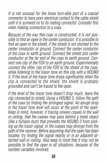
8.1.4.5: Power Wires:The FOX and HOUND 3 cannot trace or identify “live” powerwires. To use a FOX and HOUND 3 to trace a power wire,power must be removed from the wire, and all loads mustbe removed from the wire. This may be as simple as turningthe circuit breaker off, and turning off all of the loads.
NM-B (Non-Metallic wires, sometimes called “Romex”) canbe traced by putting one clip of the FOX on the ground orneutral, and the other clip on the hot wire. Trace the wiresusing a HOUND 3 in the usual manner.
If the target wires are in a metal conduit, they cannot betraced until they emerge from the conduit.
To identify the wires, if using the floating method, momen-tarily short the suspected wires together while listening tothe FOX signal with the HOUND 3. Warning, take care not toshort together live wires! If the FOX signal is completelykilled (not heard on the HOUND 3), the selected wires areprobably the target pair. If the signal is not completely killed,the wrong wires have been selected, or there is an open faultin the wires, and crosstalk is being picked up from the otherwires.
To identify the wires, if using the grounded method, mo-mentarily short the suspected wire to ground while listeningto the FOX signal with the HOUND 3. Warning, take care notto short together live wires! If the FOX signal is completelykilled (not heard on the HOUND 3), the selected wire is prob-
38
ably the target wire. If the signal is not completely killed, thewrong wire has been selected, or there is an open fault inthe wire, and crosstalk is being picked up from the otherwires. (This will not work if a fake ground is being used. Anactual ground is required to perform this test).
8.1.4.6: Resistance Heating Wires:The FOX and a HOUND 3 can be used to trace the path of aresistance heating wire in a plaster wall or ceiling. This isusually performed to find an open in the wire. It is best if theuser is familiar with resistance heating techniques, particu-larly in regard to the typical patterns used for the wire path.The wire is usually in a serpentine pattern, with the wire spac-ing and orientation varying depending on the amount of heatneeded in different areas of the room.
Finding the open can be a challenge. Several techniques canbe, and should be, used.
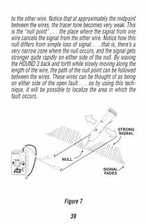
It helps if the user performs a few experiments before tryingto find the open. See Figure 7. Attach a few pieces of wire(any kind) more than several feet long to each clip of theFOX. Lay the wires out on a non-conducting surface (a woodfloor with no metal in the vicinity..... nails are OK, but makesure there’s no metal furnace duct below the floor) parallelto each other, about 4 “ apart. Using a HOUND 3, trace alongone of the wires, in normal fashion, noting how the tracertone becomes stronger as the wire is approached. Now tracealong the other wire, noting that it behaves just like the pre-vious wire. Now, slowing move the HOUND 3 from one wire
39
to the other wire. Notice that at approximately the midpointbetween the wires, the tracer tone becomes very weak. Thisis the “null point” . . . the place where the signal from onewire cancels the signal from the other wire. Notice how thisnull differs from simple loss of signal . . . that is, there’s avery narrow zone where the null occurs, and the signal getsstronger quite rapidly on either side of the null. By wavingthe HOUND 3 back and forth while slowly moving along thelength of the wire, the path of the null point can be followedbetween the wires. These wires can be thought of as beingon either side of the open fault . . . so by using this tech-nique, it will be possible to localize the area in which thefault occurs.
TRIPLETT
TONE HI
LO
CONTINUITYTALK
WARBLE
OFF / LINE POLARITY
STRONGSIGNAL
NULL
SIGNALFADES
Figure 7
40
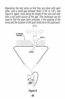
Reposition the test wires so that they are inline with eachother, with a small gap between them (1/16" to 1/8"). SeeFigure 8. Again, trace along the length of the wire and notehow a null point occurs at the gap. This technique can beused to find the open fairly precisely, if the spacing of thewires and the location of the open lends its to this approach.
TRIPLETT
TONE HI
LO
CONTINUITYTALK
WARBLE
OFF / LINE POLARITY
STRONGSIGNAL
OPEN
NULL
Figure 8
41
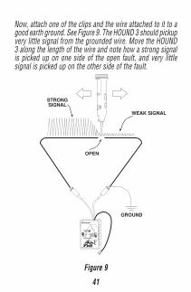
Now, attach one of the clips and the wire attached to it to agood earth ground. See Figure 9. The HOUND 3 should pickupvery little signal from the grounded wire. Move the HOUND3 along the length of the wire and note how a strong signalis picked up on one side of the open fault, and very littlesignal is picked up on the other side of the fault.
TRIPLETT
TONE HI
LO
CONTINUITYTALK
WARBLE
OFF / LINE POLARITY
STRONGSIGNAL
OPEN
WEAK SIGNAL
GROUND
Figure 9
42
For the most accurate simulation, lay out a serpentine pat-tern on the floor similar to that in the ceiling, and locate theopen in different places, using the nulling and the groundingtechnique. Have an assistant position the open fault whileyou are out of the room, and then cover the wire with card-board, newspaper, plywood, etc. . . . and see if you can findthe open. You’ll probably find that the open is sometimesfound in the wrong place. Notice what wire configurationcauses this to happen and experiment with the nulling andgrounding techniques to see if a method can be figured outthat will work in these situations.
To test the actual resistance heating circuit, disconnect theends of the heating wires from the power source. This canusually be done at the thermostat that controls the room.Attach the clips of the FOX to the wires (one clip to eachwire) and use the nulling and grounding techniques dis-cussed above, and any other methods learned from yourexperiments, to find the open fault.
8.1.4.7: Cars:Wires can be traced in cars or similar metal bodied vehiclesusing the grounded method. The metal body of the car actsas a ground, and as a shield. This means that, compared totracing in a wood frame structure, it will be necessary toplace the HOUND 3 closer to the target wire to pick up atracer tone.
Connect one clip of the FOX to the metal chassis of the car,and the other clip to the wire to be traced. As in other appli-
43
cations, the far end of the wire must be disconnected fromany loads or any other wires, or the tracer tone will be shortedout, or it will migrate into other wires. Because wires adja-cent to the target wire will often acts as shields, and be-cause the wires in cars are often bundled together into har-nesses, it may be difficult to follow the target wire throughthe harness. Try to locate the wire as it emerges from theharness.
Find an open fault by tracing along the wire until the tracertone drops dramatically in level. Shorting the far end of theopen wire to chassis ground may help. If the wire is bundledin a harness, it may be difficult, if not impossible to locatethe open without unbundling the harness. In these cases, itis sometimes more expedient to run a new wire to replacethe open wire.
8.1.4.8: Boats:Wiring tracing on metal hulled boats is similar to tracingwires in cars (see above).
If tracing wires in a boat with a non-conductive hull (woodor fiberglass) that is in the water, the grounded method canbe used, but the water will act as the ground. Attach one clipof the FOX to a metal object that is in contact with the water,and the other clip to the wire to be traced. If necessary, at-tach an extension wire to the FOX so that the clip will reachthe “grounded” metal object. If there is no grounded metalobject, simply drop the extension wire overboard into thewater.
44
If tracing wires in a boat that is out of the water, attach oneclip of the FOX to the metal trailer frame, or to a groundedmetal object. As before, an extension wire can be used ifnecessary.
8.1.4.9: Alarm / Security Wires:Alarm and security wires can be traced like other wires..
8.1.4.10: Miscellaneous Multiwire Cables:Some general principles are important to keep in mind whenlocating and tracing wires and cables.
Any wire with a signal on it, which runs parallel to anotherwire or wires tends to couple its signal to the other wires(crosstalk). The closer the wires are together, and the longerthe parallel run, the more signal that is coupled. This situa-tion occurs in multiwire cables, and when wires are bundledtogether when installed.
Luckily, if the other wires are low impedance (they have loadson them), the coupled signal will be lower in level. So, ingeneral its best to disconnect the wire being traced from itsloads, leaving other paralleling wires still connected to theirloads. If the other wires do not have loads (like when theyare being installed), it helps to temporarily connect one endof the wires to earth ground, so that they do not interferewith the trace.
The loading effect can also be used when trying to locate anopen fault in a wire in a multiwire cable. By leaving the loads
45
on the unfaulted wires, the tracer tone will be reduced inlevel on the unfaulted wires, and make locating the openeasier. In fact, if the other wires are unconnected, it helps totemporarily connect them to earth ground, so that they sup-press the effect of the coupled signals. It may also help toconnect the far end of the open faulted wire to earth ground.Doing this will produce the most distinct change in tracertone level when the HOUND 3 passes over the location ofthe open.
8.2: HOUND 3 Details (refer to Figure 2)
8.2.1: Power ButtonThe Power Button (EE) is typically pressed and held whilethe HOUND 3 is being used. When pressed, the Amplifierand Speaker (LL) is activated, and the LED lights (CC) areturned on. Release the button to turn the product off.
8.2.2: Signal Strength IndicatorThe Signal Strength Indicator (DD) is used to indicate thepresence of a signal when it may be difficult to hear the sig-nal coming from the speaker (because of high ambient noiselevels). It will glow brighter as the received signal strengthincreases. The brightness will be seen to pulsate with thecharacteristics of the received signal.
Helpful HintThe Signal Strength Indicator responds to any received sig-nal. Any sound normally heard in the speaker will cause theIndicator to light. The user will note that the HOUND 3 will
46
“pick up” signals from electrical devices other than the FOX.Probably the most notable signal, a buzzing sound, comesfrom fluorescent lights. Other sounds can often be heardwhen the HOUND 3 is placed near a TV, computer, or otherelectronic device. The Signal Strength Indicator can’t differ-entiate between these signals…… so if the user is observ-ing just the Indicator, without being able to hear the speaker,he may mistake an interfering signal for the target signal.This is where the earphone is handy. By using the earphone,the user can determine if the signal that the Indicator is re-sponding to is the target signal.
8.2.3: Sensitivity ControlThe Sensitivity Control (FF) adjusts the loudness of the soundfrom the Speaker. Usually, when initially searching for thetarget signal, the Control is set to maximum. At this maxi-mum setting, electronic noises from electrical wiring or de-vices may be heard. When the target signal is heard, theuser can track the signal to its source by moving the HOUND3 in the direction that makes the sound of the target signalget louder. As the loudness of the target signal increases,the Control setting can be reduced, which will reduce theloudness of the other interfering sounds. Repeating this pro-cess will lead the user in the direction of the wire with thetarget signal on it.
Helpful HintThe user can often track the FOX signal to its source withoutadjusting the Sensitivity Control. When the target wire is ina group of wires, adjusting the Control can help determine
47
which wire is the target wire. In this situation, it often helpsto reduce the Control setting, so changes in loudness areeasier to discern. Also, the Control may be used to reducethe loudness of the HOUND 3 in quiet office surroundings,so its use is less obtrusive to nearby workers.
8.2.4: Earphone JackThe Earphone Jack (GG) accepts a standard 1/8" mini-plug.This type is often used with portable music playing devices.The earphone may be either a stereo or mono type. For bestresults, the lead wire should be shielded to reduce the pos-sibility of feedback occurring between the lead wire and theHOUND 3’s probe. When the plug is inserted into the jack,the HOUND 3’s speaker is turned off, and the sound can onlybe heard through the earphone.
To use the earphone, set the HOUND 3’s Sensitivity Controlto minimum, plug the earphone into jack, and press thePower button. Adjust the Control for a comfortable soundlevel in the earphone.
Helpful HintSetting the Sensitivity Control to minimum prior to usingthe earphone, as previously described, can often save theuser from a jarring experience. Sounds that are not very loudin the Speaker, can be very loud in the earphone. While theHOUND 3 does provide some compensation for this, theearphone loudness can varying greatly depending on theearphones actually used.

48
In some situations, the HOUND 3 may have a tendency to“feedback” at high Sensitivity settings. The feedback maysound like a howling or squealing sound coming from theSpeaker. To suppress this effect, the Sensitivity setting canbe reduced, or the user may find that touching an unglovedfinger to the earphone jack may help.
8.2.5: LED LightsThe white LED Lights (CC) provide light for performing testsin poorly lit areas. The LEDs do not interfere with the targetsignal. If fluorescent lighting is causing a lot of interferencewith the target signal, the user may find it helpful to turn offthe lighting temporarily, and use the non-interfering illumi-nation provided by the LEDs.
8.2.6: Conductive Plastic(AA) & Metal Probes(BB)Two probes are provided with the HOUND 3. They are easilychanged by screwing and un-screwing them from the tip ofthe HOUND 3.
The metal conical probe is rugged and durable. If workingwith low voltage wiring, the metal probe can provide a sig-nificant increase in signal loudness when the metal in thetarget wire, or a metal contact connected to the target wire,is touched. This sometimes aids in identifying the target wire.For example, the metal probe is often used to drag along thecontacts on a telephone punchdown block. In situationswhere the metal probe may short a circuit, leading to dis-ruption of the circuit operation, or may short a power cir-cuit, possibly causing equipment damage and user injury,
49
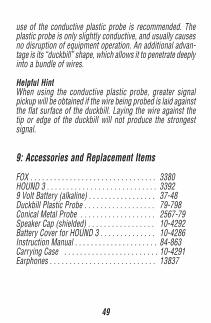
use of the conductive plastic probe is recommended. Theplastic probe is only slightly conductive, and usually causesno disruption of equipment operation. An additional advan-tage is its “duckbill” shape, which allows it to penetrate deeplyinto a bundle of wires.
Helpful HintWhen using the conductive plastic probe, greater signalpickup will be obtained if the wire being probed is laid againstthe flat surface of the duckbill. Laying the wire against thetip or edge of the duckbill will not produce the strongestsignal.
9: Accessories and Replacement Items
FOX . . . . . . . . . . . . . . . . . . . . . . . . . . . . . . . . 3380HOUND 3 . . . . . . . . . . . . . . . . . . . . . . . . . . . . 33929 Volt Battery (alkaline) . . . . . . . . . . . . . . . . . 37-48Duckbill Plastic Probe . . . . . . . . . . . . . . . . . . 79-798Conical Metal Probe . . . . . . . . . . . . . . . . . . . 2567-79Speaker Cap (shielded) . . . . . . . . . . . . . . . . . 10-4292Battery Cover for HOUND 3 . . . . . . . . . . . . . . 10-4286Instruction Manual . . . . . . . . . . . . . . . . . . . . . 84-863Carrying Case . . . . . . . . . . . . . . . . . . . . . . . . 10-4291Earphones . . . . . . . . . . . . . . . . . . . . . . . . . . . 13837

50
10: Warranty Info
ONE YEAR LIMITED WARRANTYThe Triplett Corporation warrants instruments and test equipmentmanufactured by it to be free from defective material or workman-ship and agrees to repair or replace such products which, undernormal use and service, disclose the defect to be the fault of ourmanufacturing, with no charge within one year of the date of originalpurchase for parts and labor. If we are unable to repair or replacethe product, we will make a refund of the purchase price. Consultthe Instruction Manual for instructions regarding the proper use andservicing of instruments and test equipment. Our obligation underthis warranty is limited to repairing, replacing, or making refund onany instrument or test equipment which proves to be defective withinone year from the date of original purchase.
This warranty does not apply to any of our products which have beenrepaired or altered by unauthorized persons in any way so as, in oursole judgment, to injure their stability or reliability, or which havebeen subject to misuse, abuse, misapplication, negligence, accidentor which have had the serial numbers altered, defaced, or removed.Accessories, including batteries and fuses, not of our manufactureused with this product are not covered by this warranty.
To register a claim under the provisions of this warranty, return theinstrument or test equipment to Triplett Corporation, Service De-partment, One Triplett Drive, Bluffton, Ohio 45817, transportationprepaid. Upon our inspection of the product, we will advise you asto the disposition of your claim.

51
ALL WARRANTIES IMPLIED BY LAW ARE HEREBY LIMITED TO APERIOD OF ONE YEAR FROM DATE OF PURCHASE, AND THE PRO-VISIONS OF THE WARRANTY ARE EXPRESSLY IN LIEU OF ANYOTHER WARRANTIES EXPRESSED OR IMPLIED.
The purchaser agrees to assume all liability for any damages andbodily injury which may result from the use or misuse of the prod-uct by the purchaser, his employees, or others, and the remediesprovided for in this warranty are expressly in lieu of any other liabil-ity Triplett Corporation may have, including incidental or consequen-tial damages.
Some states (USA ONLY) do not allow the exclusion or limitation ofincidental or consequential damages, so the above limitation or ex-clusion may not apply to you. No representative of Triplett Corpora-tion or any other person is authorized to extend the liability of TriplettCorporation in connection with the sale of its products beyond theterms hereof.
Triplett Corporation reserves the right to discontinue models at anytime, or change specifications, price or design, without notice andwithout incurring any obligation.
This warranty gives you specific legal rights, and you may have otherrights which vary from state to state.

52
© Triplett Corporation All Rights Reserved
TRIPLETTTriplett Corporation One Triplett Drive Bluffton, OH 45817800-TRIPLETT FAX: 419-358-7956 www.triplett.com