TRIO-20.0-TL / TRIO-27.6-TL - germansolar.de · - 1 - 000001BG INSTRUCTION MANUAL FOR THE INSTALLER...
101
- 1 - 000001BG INSTRUCTION MANUAL FOR THE INSTALLER TRIO-20.0-TL / TRIO-27.6-TL This manual must be considered as an integral part of the equipment, and must be available at all times to everyone who interacts with the equipment. The manual must always accompany the equipment, even when it is transferred to another user. Operators are under an obligation to read this manual and strictly follow the instructions given in it, because Power-One cannot be held responsible for damage caused to people or property, or for damage to the equipment, if the conditions described below are not complied with. The customer is under an obligation to keep the industrial secret, and therefore the following documentation and its annexes non may not be tampered with or modified, reproduced or transferred to third parties, without the authorization of Power-One. - Cod. M000001BG Italy Facility Via S. Giorgio, 642 52028 Terranuova Bracciolini Italy +39 055 9195 1 Camarillo Facility 740 Calle Plano Camarillo, California, 93012 United States 805-987-8741 http://www.power-one.com TRANSLATION OF THE ORIGINAL INSTRUCTIONS
Transcript of TRIO-20.0-TL / TRIO-27.6-TL - germansolar.de · - 1 - 000001BG INSTRUCTION MANUAL FOR THE INSTALLER...

- 1 -
0000
01BG
INSTRUCTION MANUAL FOR THE INSTALLER
TRIO-20.0-TL / TRIO-27.6-TL
This manual must be considered as an integral part of the equipment, and must be available at all times to
everyone who interacts with the equipment. The manual must always accompany the equipment,
even when it is transferred to another user.
Operators are under an obligation to read this manual and strictly follow the instructions given in it,
because Power-One cannot be held responsible for damage caused to people or property, or for damage to the equipment, if the conditions described below are not complied with.
The customer is under an obligation to keep the industrial secret, and therefore the following documentation and its annexes
non may not be tampered with or modified, reproduced or transferred to third parties, without the authorization of Power-One.
- Co
d. M
0000
01BG
Italy Facility Via S. Giorgio, 642 52028 Terranuova Bracciolini Italy +39 055 9195 1 Camarillo Facility 740 Calle Plano Camarillo, California, 93012 United States 805-987-8741
http://www.power-one.com
TRANSLATION OF THE ORIGINAL INSTRUCTIONS

- 2 -
0000
02AG
1 - Introduction and general informationWarranty and supply conditions
The warranty conditions are described in a special certificate sup-plied with the equipment. The warranty conditions are also consid-ered to be valid if the customer complies with what is described in this manual; any conditions departing from those described below must be expressly agreed in the purchase order.
Power-one declares that the equipment is in conformity with the current provisions of law in the European Economic Community and issues a DECLARATION OF CON-FORMITY for it.
Not included in the supply
Power-one accepts no liability for failure to comply with the instructions for correct installation and cannot be held responsible for the systems upstream or downstream of the equipment it has supplied.It is absolutely forbidden to make modifications to the equipment.The Customer is fully responsible for any modifications made to the system.
It is not possible to anticipate the great number of installations and envi-ronments in which the equipment will be installed; it is therefore neces-sary to check the following: adequate spaces, suitable for housing the equipment; airborne noise produced based on the environment; pos-sible flammability conditions.
Power-one cannot be held responsible for non-production even if this is due to failures of the equipment, or the data communication system.
Power-one CANNOT be held responsible for defects or malfunctioning arising from: improper use of the equipment; deterioration due to trans-port or particular environmental conditions; failure to carry out mainte-nance or improper maintenance; tampering or temporary repairs; use or installation carried out by unqualified people.
Power-one CANNOT be held responsible for disposal of: displays, ca-bles, batteries, accumulators, etc. The customer must dispose of these substances, which are potentially harmful to the environment, in accord-ance with the regulations in force in the country of installation.
1

- 3 -
0000
03BG
Contents
Introduction and general information 1 1 - Introduction and general information .......................................................2
Warranty and supply conditions ...................................................................................2Not included in the supply .......................................................................................................2
Contents ...........................................................................................................................3Reference number index ................................................................................................7Graphical representation of references .......................................................................8Analytical index ...............................................................................................................9The document and who it is for ..................................................................................13
Purpose and structure of the document ...............................................................................13List of annexes .....................................................................................................................13Staff characteristics ...............................................................................................................13
Reference regulations .................................................................................................14Symbols and signs .......................................................................................................15Field of use, general conditions .................................................................................16
Intended or allowed use ........................................................................................................16Limits of the field of use ........................................................................................................16Improper or disallowed use ..................................................................................................16
2 - Characteristics ................................................................................17General conditions .......................................................................................................17Models and range of equipment..................................................................................18
Identification of the equipment and the manufacturer ..........................................................18Characteristics and technical data .............................................................................19
Overall dimensions ...............................................................................................................21Tightening torques ................................................................................................................21
Efficiency curves ...........................................................................................................22Power Derating ..............................................................................................................23
Power reduction due to environmental conditions ................................................................23Power reduction due to the input voltage .............................................................................23
Characteristics of a photovoltaic generator ..............................................................25Strings and Arrays .................................................................................................................25
Description of the equipment ......................................................................................26Operating diagram ................................................................................................................26Connection of several inverters together ..............................................................................27Notes on the sizing of the system .........................................................................................27Functionality and components of the equipment .................................................................28Topographic diagram of the equipment ................................................................................29
Protective devices.........................................................................................................31Anti-Islanding ........................................................................................................................31Ground fault in the photovoltaic panels ................................................................................31String fuses ...........................................................................................................................31Overvoltage surge arresters .................................................................................................31Further protective devices.....................................................................................................31
- 4 -
0000
03BG
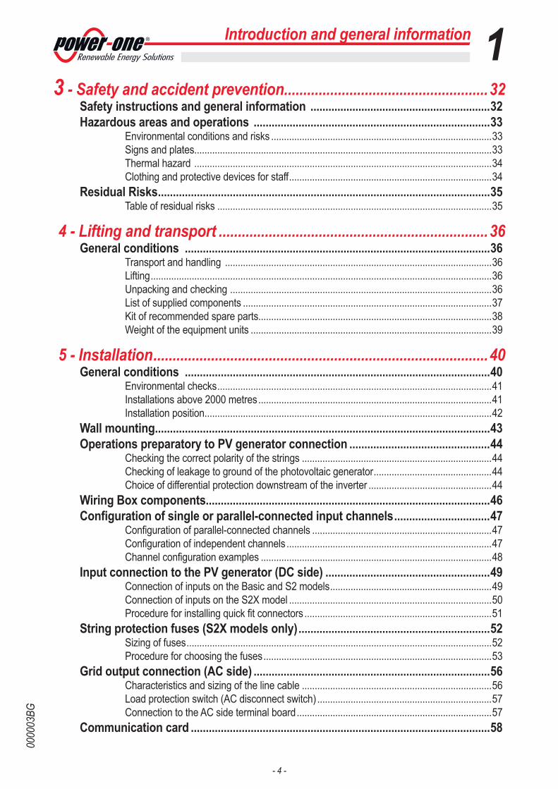
Introduction and general information 13 - Safety and accident prevention .....................................................32
Safety instructions and general information ............................................................32Hazardous areas and operations ...............................................................................33
Environmental conditions and risks ......................................................................................33Signs and plates....................................................................................................................33Thermal hazard ....................................................................................................................34Clothing and protective devices for staff ...............................................................................34
Residual Risks ...............................................................................................................35Table of residual risks ...........................................................................................................35
4 - Lifting and transport ......................................................................36General conditions ......................................................................................................36
Transport and handling ........................................................................................................36Lifting .....................................................................................................................................36Unpacking and checking ......................................................................................................36List of supplied components .................................................................................................37Kit of recommended spare parts...........................................................................................38Weight of the equipment units ..............................................................................................39
5 - Installation .......................................................................................40General conditions ......................................................................................................40
Environmental checks ...........................................................................................................41Installations above 2000 metres ...........................................................................................41Installation position ................................................................................................................42
Wall mounting ................................................................................................................43Operations preparatory to PV generator connection ...............................................44
Checking the correct polarity of the strings ..........................................................................44Checking of leakage to ground of the photovoltaic generator ..............................................44Choice of differential protection downstream of the inverter ................................................44
Wiring Box components...............................................................................................46Configuration of single or parallel-connected input channels ................................47
Configuration of parallel-connected channels ......................................................................47Configuration of independent channels ................................................................................47Channel configuration examples ..........................................................................................48
Input connection to the PV generator (DC side) .......................................................49Connection of inputs on the Basic and S2 models ...............................................................49Connection of inputs on the S2X model ...............................................................................50Procedure for installing quick fit connectors .........................................................................51
String protection fuses (S2X models only) ................................................................52Sizing of fuses .......................................................................................................................52Procedure for choosing the fuses .........................................................................................53
Grid output connection (AC side) ...............................................................................56Characteristics and sizing of the line cable ..........................................................................56Load protection switch (AC disconnect switch) ....................................................................57Connection to the AC side terminal board ............................................................................57
Communication card ....................................................................................................58

- 5 -
0000
03BG
Introduction and general information 1Connections to the communication card ...................................................................59
Serial communication (RS485) .............................................................................................59Procedure for connection to a monitoring system ................................................................60Monitoring system via serial (RS485) ..................................................................................61Monitoring system via Radiomodule .....................................................................................62Configurable relay .................................................................................................................62Environmental sensors ........................................................................................................64Specifications of environmental sensors ..............................................................................64Connection diagrams for environmental sensors .................................................................65Remote control ......................................................................................................................66Auxiliary 5 V output ...............................................................................................................66SD card .................................................................................................................................66
Setting the country and the language ........................................................................67Saving the country standard and language ..........................................................................68
6 - Instruments .....................................................................................69General conditions ......................................................................................................69Display and keypad ......................................................................................................70
Description of symbols and display fields .............................................................................70Description of the keypad .....................................................................................................72
7 - Operation .........................................................................................73General conditions ......................................................................................................73Monitoring and data transmission ..............................................................................74
User interface mode ..............................................................................................................74Types of data available .........................................................................................................74
Commissioning .............................................................................................................75Dynamic behaviour of the display .........................................................................................77
LED behaviour ...............................................................................................................78Specifications on the behaviour of the LEDs ........................................................................79Insulation fault LED ...............................................................................................................79
Description of the menus .............................................................................................80Using the panel buttons ........................................................................................................80Statistics menu ......................................................................................................................81Settings menu .......................................................................................................................83Information menu ..................................................................................................................87
AUTOTEST procedure ..................................................................................................88Description of the tests that can be carried out ....................................................................88
8 - Maintenance ....................................................................................90General conditions ......................................................................................................90
Routine maintenance ............................................................................................................91Special maintenance .............................................................................................................91Alarm Messages ...................................................................................................................92
Verification of ground leakage ...................................................................................98Behaviour of a system without leakage ................................................................................98Behaviour of a system with leakage .....................................................................................99

- 6 -
0000
03BG
Introduction and general information 1Measuring the insulation resistance (Riso) .............................................................100Storage and dismantling ...........................................................................................101
Storage of the equipment or prolonged stop ......................................................................101Dismantling, decommissioning and disposal ......................................................................101

- 7 -
0000
03BG
Reference number index01, bracket ............................................................................................................................................... 35, 4302, wiring box .................................................................................................. 18, 21, 31, 43, 46, 49, 56, 9103, inverter .................................................................................................................................. 43, 46, 49, 5604, cover............................................................................................................................................. 43, 49, 5605, clamp screw ............................................................................................................................................... 4306, handles ................................................................................................................................................ 39, 4307, connector screws ....................................................................................................................................... 4308, front cover .................................................................................................................................................. 9109, communication card ................................................................................................ 47, 58, 59, 62, 66, 9110, service cable glands ........................................................................................................................... 59, 6211, DC cable glands .................................................................................................................................. 21, 4912, jumpers ...................................................................................................................................................... 4713, DC input terminal board ............................................................................................................... 21, 47, 4914, AC+DC disconnect switch .................................................................................................... 18, 46, 49, 7515, DC overvoltage surge arresters ............................................................................................ 18, 31, 46, 9116, AC cable gland ............................................................................................................................. 21, 56, 5717, AC output terminal board ............................................................................................................. 21, 56, 5718, AC overvoltage surge arresters ............................................................................................ 18, 31, 46, 9119, Input connectors (MPPT1) ......................................................................................................................... 4620, Input connectors (MPPT2) ......................................................................................................................... 4621, anti-condensation valve ............................................................................................................................. 4622, string fuses ..................................................................................................................... 18, 31, 46, 50, 5223, display ....................................................................................................... 67, 70, 72, 74, 78, 79, 80, 9224, keypad ........................................................................................................................................................ 7225, LED panel ............................................................................................................... 72, 74, 76, 78, 79, 8026, heatsink ...................................................................................................................................................... 91
Introduction and general information 1

- 8 -
0000
03BG
Introduction and general information 1Graphical representation of references
03
06
012526
08
09
05
0402
07
CARDCOM
CARDMEMORY
1
1
10 1614 1711
09
10 161411
1213
21
CARDCOM
CARDMEMORY
1
1
10 1614 1722
10 1614 2119 20
09 15 181213
BA
SE /
S2S2
X
23 - 24
- 9 -
0000
03BG
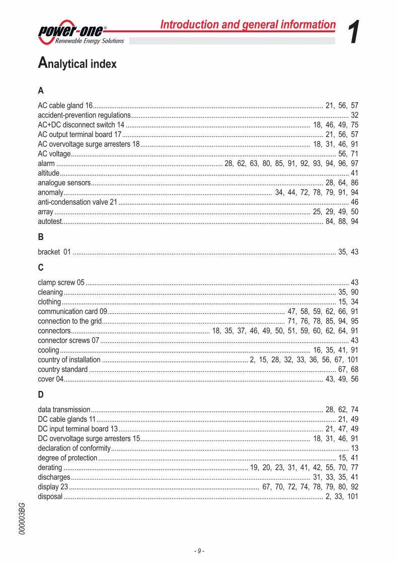
Introduction and general information 1Analytical index
AAC cable gland 16 .............................................................................................................................. 21, 56, 57accident-prevention regulations ....................................................................................................................... 32AC+DC disconnect switch 14 ..................................................................................................... 18, 46, 49, 75AC output terminal board 17 .............................................................................................................. 21, 56, 57AC overvoltage surge arresters 18 ............................................................................................. 18, 31, 46, 91AC voltage ................................................................................................................................................. 56, 71alarm ........................................................................................... 28, 62, 63, 80, 85, 91, 92, 93, 94, 96, 97altitude .............................................................................................................................................................. 41analogue sensors ............................................................................................................................... 28, 64, 86anomaly .................................................................................................................. 34, 44, 72, 78, 79, 91, 94anti-condensation valve 21 .............................................................................................................................. 46array ............................................................................................................................................ 25, 29, 49, 50autotest ............................................................................................................................................... 84, 88, 94
Bbracket 01 ................................................................................................................................................ 35, 43
Cclamp screw 05 ................................................................................................................................................ 43cleaning ..................................................................................................................................................... 35, 90clothing ...................................................................................................................................................... 15, 34communication card 09 ................................................................................................. 47, 58, 59, 62, 66, 91connection to the grid .................................................................................................... 71, 76, 78, 85, 94, 95connectors ............................................................................ 18, 35, 37, 46, 49, 50, 51, 59, 60, 62, 64, 91connector screws 07 ........................................................................................................................................ 43cooling ......................................................................................................................................... 16, 35, 41, 91country of installation ................................................................................ 2, 15, 28, 32, 33, 36, 56, 67, 101country standard ....................................................................................................................................... 67, 68cover 04.............................................................................................................................................. 43, 49, 56
Ddata transmission ............................................................................................................................... 28, 62, 74DC cable glands 11 ................................................................................................................................... 21, 49DC input terminal board 13 ................................................................................................................ 21, 47, 49DC overvoltage surge arresters 15 ............................................................................................. 18, 31, 46, 91declaration of conformity .................................................................................................................................. 13degree of protection .................................................................................................................................. 15, 41derating ..................................................................................................... 19, 20, 23, 31, 41, 42, 55, 70, 77discharges ................................................................................................................................... 31, 33, 35, 41display 23 ........................................................................................................ 67, 70, 72, 74, 78, 79, 80, 92disposal .............................................................................................................................................. 2, 33, 101

- 10 -
0000
03BG
Introduction and general information 1Eefficiency ............................................................................................................................................ 22, 29, 91electrocution hazards ................................................................................................................................ 49, 57electromagnetic interference ........................................................................................................................... 41electrostatic charges .......................................................................................................................... 16, 34, 90energy conservation ......................................................................................................................................... 22environmental conditions .......................................................................... 2, 16, 23, 26, 28, 33, 64, 91, 100environmental sensors ....................................................................................................................... 58, 64, 65eyebolts ....................................................................................................................................... 36, 38, 39, 43
Ffans ................................................................................................................................................................... 91fault ................................................................................ 31, 44, 45, 52, 55, 72, 78, 79, 80, 91, 93, 94, 98field of use ........................................................................................................................................................ 16fire ............................................................................................................................................................. 34, 52firmware .................................................................................................................................................... 28, 87flammability .......................................................................................................................................... 2, 16, 33front cover 08 ................................................................................................................................................... 91
Ggrid 16, 23, 25, 26, 27, 28, 29, 31, 34, 41, 44, 56, 57, 62, 63, 66, 67, 68, 70, 71, 72, 74, 75, 76, 77, 78, 79, 84, 85, 86, 87, 88, 89, 90, 91, 93, 94, 95, 96, 100grid company ........................................................................................................................ 28, 70, 94, 95, 96grid standard ........................................................................................................................ 67, 71, 75, 87, 88grid voltage ...................................................... 23, 25, 31, 71, 72, 75, 76, 78, 85, 88, 89, 93, 94, 95, 96grounded ............................................................................................................................................ 15, 16, 60ground fault ................................................................................................................................. 31, 45, 72, 98ground leakage .................................................................................................................... 44, 92, 93, 98, 99
Hhandles 06 ................................................................................................................................................. 39, 43heatsink 26 ....................................................................................................................................................... 91humidity ................................................................................................................................ 16, 33, 35, 36, 41
Iinput channels ............................................................................................................... 37, 46, 47, 58, 92, 93Input connectors (MPPT1) 19 .......................................................................................................................... 46Input connectors (MPPT2) 20 .......................................................................................................................... 46input power ....................................................................................................................................................... 78inputs .................................................................................................. 28, 47, 48, 49, 50, 78, 86, 87, 92, 93input voltage ....................................................................................... 23, 26, 44, 63, 70, 78, 85, 92, 93, 96installation conditions .................................................................................................................. 18, 32, 47, 48insulation resistance .............................................................................. 44, 76, 78, 92, 93, 94, 95, 96, 100inverter 03 ................................................................................................................................... 43, 46, 49, 56inverter operation ............................................................................................................................... 23, 26, 48islanding ............................................................................................................................................. 20, 25, 31
- 11 -
0000
03BG
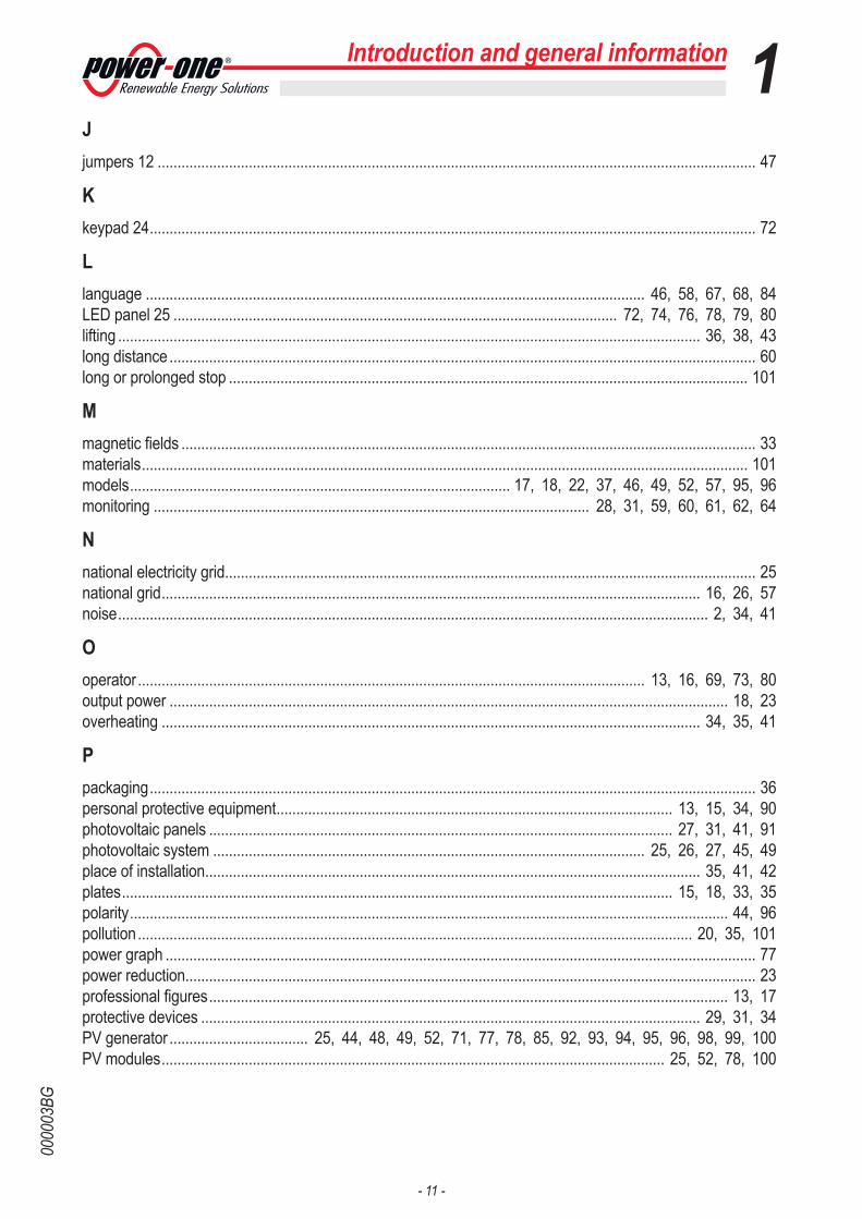
Introduction and general information 1Jjumpers 12 ....................................................................................................................................................... 47
Kkeypad 24 ......................................................................................................................................................... 72
Llanguage .............................................................................................................................. 46, 58, 67, 68, 84LED panel 25 ................................................................................................................ 72, 74, 76, 78, 79, 80lifting ................................................................................................................................................... 36, 38, 43long distance .................................................................................................................................................... 60long or prolonged stop ................................................................................................................................... 101
Mmagnetic fields ................................................................................................................................................. 33materials ......................................................................................................................................................... 101models ................................................................................................ 17, 18, 22, 37, 46, 49, 52, 57, 95, 96monitoring .............................................................................................................. 28, 31, 59, 60, 61, 62, 64
Nnational electricity grid...................................................................................................................................... 25national grid ........................................................................................................................................ 16, 26, 57noise ..................................................................................................................................................... 2, 34, 41
Ooperator ................................................................................................................................ 13, 16, 69, 73, 80output power ............................................................................................................................................. 18, 23overheating ........................................................................................................................................ 34, 35, 41
Ppackaging ......................................................................................................................................................... 36personal protective equipment .................................................................................................... 13, 15, 34, 90photovoltaic panels ..................................................................................................................... 27, 31, 41, 91photovoltaic system ............................................................................................................. 25, 26, 27, 45, 49place of installation ............................................................................................................................. 35, 41, 42plates ........................................................................................................................................... 15, 18, 33, 35polarity ....................................................................................................................................................... 44, 96pollution ............................................................................................................................................ 20, 35, 101power graph ..................................................................................................................................................... 77power reduction................................................................................................................................................ 23professional figures ................................................................................................................................... 13, 17protective devices .............................................................................................................................. 29, 31, 34PV generator ................................... 25, 44, 48, 49, 52, 71, 77, 78, 85, 92, 93, 94, 95, 96, 98, 99, 100PV modules ............................................................................................................................... 25, 52, 78, 100
- 12 -
0000
03BG
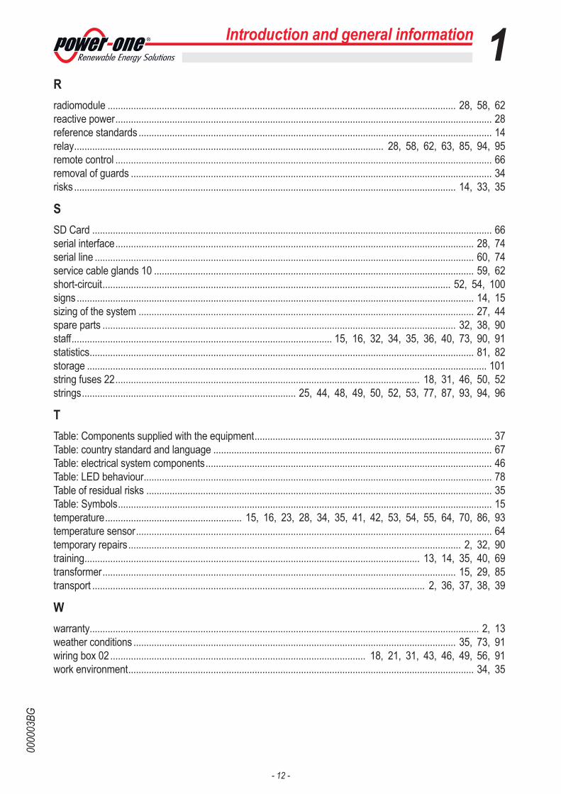
Introduction and general information 1Rradiomodule ....................................................................................................................................... 28, 58, 62reactive power .................................................................................................................................................. 28reference standards ......................................................................................................................................... 14relay ........................................................................................................................ 28, 58, 62, 63, 85, 94, 95remote control .................................................................................................................................................. 66removal of guards ............................................................................................................................................ 34risks .................................................................................................................................................... 14, 33, 35
SSD Card ........................................................................................................................................................... 66serial interface ........................................................................................................................................... 28, 74serial line ................................................................................................................................................... 60, 74service cable glands 10 ............................................................................................................................ 59, 62short-circuit ....................................................................................................................................... 52, 54, 100signs .......................................................................................................................................................... 14, 15sizing of the system .................................................................................................................................. 27, 44spare parts ......................................................................................................................................... 32, 38, 90staff ..................................................................................................... 15, 16, 32, 34, 35, 36, 40, 73, 90, 91statistics ..................................................................................................................................................... 81, 82storage ........................................................................................................................................................... 101string fuses 22 ...................................................................................................................... 18, 31, 46, 50, 52strings ................................................................................... 25, 44, 48, 49, 50, 52, 53, 77, 87, 93, 94, 96
TTable: Components supplied with the equipment ............................................................................................ 37Table: country standard and language ............................................................................................................ 67Table: electrical system components ............................................................................................................... 46Table: LED behaviour ....................................................................................................................................... 78Table of residual risks ...................................................................................................................................... 35Table: Symbols ................................................................................................................................................. 15temperature ..................................................... 15, 16, 23, 28, 34, 35, 41, 42, 53, 54, 55, 64, 70, 86, 93temperature sensor .......................................................................................................................................... 64temporary repairs ................................................................................................................................. 2, 32, 90training .................................................................................................................................. 13, 14, 35, 40, 69transformer ......................................................................................................................................... 15, 29, 85transport ................................................................................................................................. 2, 36, 37, 38, 39
Wwarranty....................................................................................................................................................... 2, 13weather conditions ............................................................................................................................. 35, 73, 91wiring box 02 ................................................................................................... 18, 21, 31, 43, 46, 49, 56, 91work environment ...................................................................................................................................... 34, 35

- 13 -
0000
04AG
Introduction and general information
The document and who it is for
Purpose and structure of the document
This operating and maintenance manual is a valid guide that will enable you to work safely and carry out the operations necessary for keeping the equipment in good working order.
The document was originally written in ITALIAN; therefore, in the event of inconsisten-cies or doubts please ask the manufacturer for the original document.
List of annexes
In addition to this operating and maintenance manual, (if applicable or on request) the following attached documentation is supplied:- EC declaration of conformity- quick installation guide- service manual for the installer- warranty
WARNING: Part of the information given in this document is taken from the original documents of the suppliers. This document contains only the information considered necessary for the use and routine maintenance of the equipment.
Staff characteristics
The customer must make sure the operator has the necessary skill and training to do his/her job. Staff in charge of using and maintaining the equipment must be skilled, aware and mature for the described tasks and must have the reliability to correctly interpret what is described in the manual.
The employment of a person who is NOT qualified, is drunk or on narcotics, has a prosthetic mitral valve or a pacemaker is strictly forbidden.
The customer is civilly liable for the qualification and mental or physical condition of the professional figures who interact with the equipment. They must always use the personal protective equipment provided for by the laws of the country of destination and whatever is provided by their employer.
1
- 14 -
0000
05BG
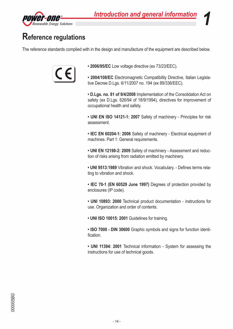
Reference regulations The reference standards complied with in the design and manufacture of the equipment are described below.
• 2006/95/EC Low voltage directive (ex 73/23/EEC).
• 2004/108/EC Electromagnetic Compatibility Directive, Italian Legisla-tive Decree D.Lgs. 6/11/2007 no. 194 (ex 89/336/EEC).
• D.Lgs. no. 81 of 9/4/2008 Implementation of the Consolidation Act on safety (ex D.Lgs. 626/94 of 18/9/1994), directives for improvement of occupational health and safety.
• UNI EN ISO 14121-1: 2007 Safety of machinery - Principles for risk assessment.
• IEC EN 60204-1: 2006 Safety of machinery - Electrical equipment of machines. Part 1: General requirements.
• UNI EN 12198-2: 2009 Safety of machinery - Assessment and reduc-tion of risks arising from radiation emitted by machinery.
• UNI 9513:1989 Vibration and shock. Vocabulary. - Defines terms rela-ting to vibration and shock.
• IEC 70-1 (EN 60529 June 1997) Degrees of protection provided by enclosures (IP code).
• UNI 10893: 2000 Technical product documentation - instructions for use. Organization and order of contents.
• UNI ISO 10015: 2001 Guidelines for training.
• ISO 7000 - DIN 30600 Graphic symbols and signs for function identi-fication.
• UNI 11394: 2001 Technical information - System for assessing the instructions for use of technical goods.
1Introduction and general information

- 15 -
0000
06AG
1Introduction and general information
Symbols and signsTable: Symbols
In the manual and/or in some cases on the equipment, the danger or hazard zones are indicated with signs, plates, symbols or icons, like the CE marking.
This points out that it is mandatory to consult the manual or original doc-ument, which must be available for future use and must not be damaged in any way.
This points out operations or situations in which staff must be very care-ful, respectively:Generic hazard or hazardous voltage
This points out a hazard due to the presence of heated areas or in any case areas that have hot parts (danger of burns).
This points out that the examined area must not be entered or that the described operation must not be carried out.
This points out that the equipment must not be worked on by anyone with a pacemaker, prosthetic mitral valve or prostheses with electronic circuits.
This points out that it is mandatory to carry out the described operations using the clothing and/or personal protective equipment provided by the employer.
IP65This indicates the degree of protection of the equipment according to IEC standard 70-1 (EN 60529 June 1997).
The system must be grounded
This indicates the allowed temperature range
This indicates the risk of electric shock. Time needed to discharge stored energy: 10 minutes
This indicates that the equipment must be disposed of in accordance with the regulations in force in the country of installation.
Respectively direct current and alternating current
There is no transformer

- 16 -
0000
07AG
Field of use, general conditions Power-One accepts no liability for damage of any kind that may arise from incorrect or careless operations.
The equipment must not be used for uses that do not fall within the intended field of use. The equipment MUST NOT be used by inexperienced staff, or by experienced staff to carry out operations on the equipment that are not in accordance with what is described in this manual and in the attached documents.
Intended or allowed use
This equipment is a multi-string inverter designed to:transform a direct electric current (DC)
coming from a photovoltaic generator (PV) into an alternating electric current (AC)
Suitable for being fed into the national grid.
Limits of the field of use
The inverter can be used only with photovoltaic modules that do not require one of the poles to be grounded.The operating current dispersed during normal operation must not exceed the limits specified in the technical specifications.Only one photovoltaic generator can be connected to the input of the inverter (do not connect batteries or other sources of power supply)The inverter can be connected to the electricity grid in qualified countries only.The inverter can be used only if all the technical characteristics are observed.
Improper or disallowed use
THE FOLLOWING ARE STRICTLY FORBIDDEN:• Installing the equipment in environments with particular flammability conditions or in adverse or disallowed environmental conditions (temperature and humidity)..• Using the equipment with the safety devices not working or disabled.• Using the equipment or parts of the equipment by connecting it to other machines or equipment, unless expressly provided for.• Modifying the operating parameters that are not accessible to the operator and/or parts of the equipment to vary the performance or change its insulations.• Cleaning with corrosive products that may corrode parts of the equipment or gener-ate electrostatic charges.• Using or installing the equipment or parts of it without having read and correctly in-terpreted the contents of the operating and maintenance manual.• Warming or drying rags and clothes on parts at temperature. Besides being danger-ous, this would compromise the ventilation and cooling of the components.
Introduction and general information 1
IP65
- 17 -
0000
08AG
2 - Characteristics
2
General conditionsThe description of the characteristics of the equipment allows its main components to be identified, to refine the technical terminology used in the manual.The technical terminology and the quick information finding system are assisted by the following:• Contents• Numerical index of references • Index.The Characteristics chapter contains information about the models, the composition of the equipment, the characteristics and technical data, the overall dimensions and the identification of the equipment.
This manual should be read in chronological order as established by the manufac-turer and the reader assumes responsibility for failure to do so. All the information is given considering each time that the information of the preceding chapters has been acknowledged.
In some cases, there may be a need to separately document the opera-tion of the software or to attach supplementary documentation to this manual for more qualified professional figures.

- 18 -
0000
09AG
Characteristics 2Models and range of equipment
The specific models of multi-string inverter that this manual is about are divided into two groups according to the maximum output power (20 kW or 27.6 kW).For inverters of equal output power, the variant between the various models is the layout of the wiring box 02.
The choice of model of inverter must be made by a qualified technician who knows about the installation conditions, the devices that will be installed outside the inverter and possible integration with an existing system.
• 20 kW three-phase MODELSTRIO-20.0-TL-OUTD: Basic version wiring boxTRIO-20.0-TL-OUTD-S2: S2 wiring box version (with AC+DC discon-nect switch 14)TRIO-20.0-TL-OUTD-S2X: S2X wiring box version (with quick fit con-nectors, string fuses 22, DC overvoltage surge arresters 15, AC over-voltage surge arresters 18 and AC+DC disconnect switch)
• 27.6 kW three-phase MODELSTRIO-27.6-TL-OUTD: Basic version wiring boxTRIO-27.6-TL-OUTD-S2: S2 wiring box version (with AC+DC discon-nect switch)TRIO-27.6-TL-OUTD-S2X: S2X wiring box version (with quick fit con-nectors, string fuses, DC overvoltage surge arresters, AC overvoltage surge arresters and AC+DC disconnect switch)
Identification of the equipment and the manufacturer
The technical data shown in this manual do not in any case replacethose shown on the plates attached to the equipment.
The plates attached to the equipment must NOT be removed, damaged, dirtied, hid-den, etc.
N.B. The plates must NOT be hidden with objects and
extraneous parts (rags, boxes, equipment, etc.); they must be
cleaned regularly and kept visible at all times.
- 19 -
0000
47AG
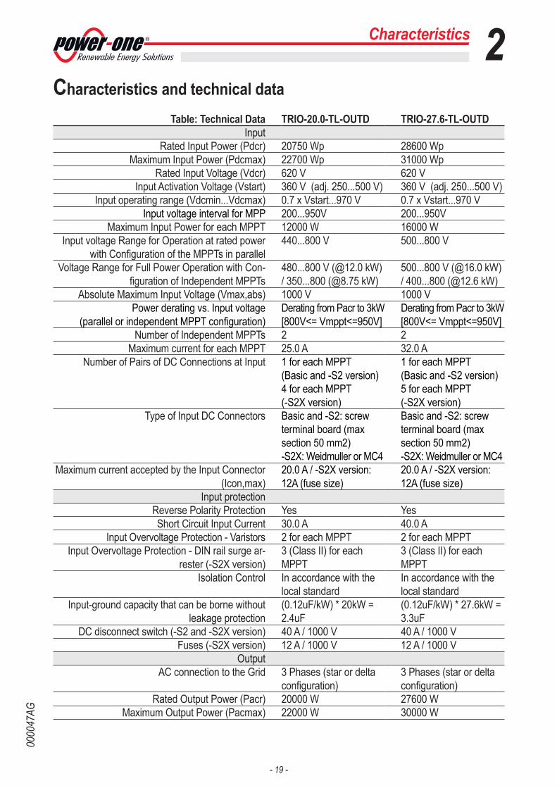
Characteristics 2Characteristics and technical data
Table: Technical Data TRIO-20.0-TL-OUTD TRIO-27.6-TL-OUTDInput
Rated Input Power (Pdcr) 20750 Wp 28600 WpMaximum Input Power (Pdcmax) 22700 Wp 31000 Wp
Rated Input Voltage (Vdcr) 620 V 620 VInput Activation Voltage (Vstart) 360 V (adj. 250...500 V) 360 V (adj. 250...500 V)
Input operating range (Vdcmin...Vdcmax) 0.7 x Vstart...970 V 0.7 x Vstart...970 VInput voltage interval for MPP 200...950V 200...950V
Maximum Input Power for each MPPT 12000 W 16000 WInput voltage Range for Operation at rated power
with Configuration of the MPPTs in parallel440...800 V 500...800 V
Voltage Range for Full Power Operation with Con-figuration of Independent MPPTs
480...800 V (@12.0 kW) / 350...800 (@8.75 kW)
500...800 V (@16.0 kW) / 400...800 (@12.6 kW)
Absolute Maximum Input Voltage (Vmax,abs) 1000 V 1000 VPower derating vs. Input voltage
(parallel or independent MPPT configuration)Derating from Pacr to 3kW[800V<= Vmppt<=950V]
Derating from Pacr to 3kW[800V<= Vmppt<=950V]
Number of Independent MPPTs 2 2Maximum current for each MPPT 25.0 A 32.0 A
Number of Pairs of DC Connections at Input 1 for each MPPT(Basic and -S2 version)4 for each MPPT(-S2X version)
1 for each MPPT(Basic and -S2 version)5 for each MPPT(-S2X version)
Type of Input DC Connectors Basic and -S2: screw terminal board (max section 50 mm2)-S2X: Weidmuller or MC4
Basic and -S2: screw terminal board (max section 50 mm2)-S2X: Weidmuller or MC4
Maximum current accepted by the Input Connector (Icon,max)
20.0 A / -S2X version:12A (fuse size)
20.0 A / -S2X version:12A (fuse size)
Input protectionReverse Polarity Protection Yes YesShort Circuit Input Current 30.0 A 40.0 A
Input Overvoltage Protection - Varistors 2 for each MPPT 2 for each MPPTInput Overvoltage Protection - DIN rail surge ar-
rester (-S2X version)3 (Class II) for each MPPT
3 (Class II) for each MPPT
Isolation Control In accordance with the local standard
In accordance with the local standard
Input-ground capacity that can be borne without leakage protection
(0.12uF/kW) * 20kW =2.4uF
(0.12uF/kW) * 27.6kW =3.3uF
DC disconnect switch (-S2 and -S2X version) 40 A / 1000 V 40 A / 1000 VFuses (-S2X version) 12 A / 1000 V 12 A / 1000 V
OutputAC connection to the Grid 3 Phases (star or delta
configuration)3 Phases (star or delta configuration)
Rated Output Power (Pacr) 20000 W 27600 WMaximum Output Power (Pacmax) 22000 W 30000 W

- 20 -
0000
47AG
Maximum apparent Output Power (Sacmax) 22300VAThe rated power is also guaranteed with cos(fi) = 0.9
31000 VAThe rated power is also guaranteed with cos(fi) = 0.9
Rated output voltage (Vacr) 400 Vac / N / PE 400 Vac / N / PEOutput Voltage Range (Vacmin...Vacmax) 320...480 Vac (1) 320...480 Vac (1)
Maximum Output Current (Iacmax) 33.0 A 45.0 ARated Output Frequency (fr) 50 Hz 50 Hz
Output Frequency Range (fmin...fmax) 47...53 Hz (2) 47...53 Hz (2)Rated Power Factor (Cosphiacr) > 0.995 (adj. ± 0.9) > 0.995 (adj. ± 0.9)
Total Harmonic Distortion of Current < 3% < 3%Type of AC Connections Screw terminal board,
maximum cross-section 35 mm2
Screw terminal board, maximum cross-section 35 mm2
Output protectionAnti-islanding Protection In accordance with the
local standardIn accordance with the local standard
Maximum AC Overcurrent protection 34.0 A 46.0 AOutput Overvoltage Protection - Varistors 4 4
Output Overvoltage Protection - DIN Rail surge ar-rester (-S2X version)
4 (Class II) 4 (Class II)
Night-time disconnection Not applicable Not applicableOperating performance
Maximum Efficiency (ηmax) 98.2% 98.2%Weighted Efficiency (EURO/CEC) 98.0% / 98.0% 98.0% / 98.0%
Power Input Threshold 40 W 40 WStand-by Consumption < 8W < 8W
NIght-time Consumption <1W <1WNIght-time Consumption (Reactive Power) 110 VAR 110 VAR
Inverter Switching Frequency 15.8 kHz 15.8 kHzCommunication
Wired Local Monitoring (opt.) PVI-USB-RS485_232, PVI-DESKTOP
PVI-USB-RS485_232, PVI-DESKTOP
Remote Monitoring (opt.) PVI-AEC-EVO, AURO-RA-UNIVERSAL
PVI-AEC-EVO, AURO-RA-UNIVERSAL
Wireless Local Monitoring (opt.) PVI-DESKTOP with PVI-RADIOMODULE
PVI-DESKTOP with PVI-RADIOMODULE
User Interface Graphic Display Graphic DisplayEnvironmental
Ambient Temperature -25...+60°C /-13...140°F with derating above 45°C/113°F
-25...+60°C /-13...140°F with derating above 45°C/113°F
Storage Temperature -40...80°C (-40...+176°F) -40...80°C (-40...+176°F)Relative Humidity 0...100% condensing 0...100% condensing
Noise Emission < 50 db(A) @ 1 m < 50 db(A) @ 1 mMaximum Operating Altitude 2000 m / 6560 ft 2000 m / 6560 ft
Environmental pollution classification for external environment
3 3
Environmental Category External External
Characteristics 2

- 21 -
0000
47AG
PhysicalEnvironmental Protection Rating IP 65 IP 65
Cooling system Natural NaturalAir Flow Required for Cooling Not applicable Not applicable
Overvoltage Category in accordance with IEC 62109-1
II (DC input)III (AC output)
II (DC input)III (AC output)
Dimensions (H x W x D) 1060 x 751 x 291 mm41.7" x 29.6" x 11.4"
1060 x 751 x 291 mm41.7" x 29.6" x 11.4"
Weight Basic and -S2: 67.0 kg / 147.70 lbS2X: 75.0 kg / 165.30 lb
Basic and -S2: 72.0 kg / 158.70 lbS2X: 80.0 kg / 176.30 lb
Packaging Dimensions (H x W x D) 737 x 800 x 1200 mm29” x 31.5” x 47.2”
737 x 800 x 1200 mm29” x 31.5” x 47.2”
Full Packaging Weight Basic and -S2: 79.0 kg / 174.10 lbS2X: 87.0 kg / 191.80 lb
Basic and -S2: 84.0 kg / 185.10 lbS2X: 92.0 kg / 202.80 lb
Mounting System Wall bracket Wall bracketExposure to UV rays Plastic covers suitable
for outdoor use.Exposure to UV rays (in accordance with UL 746C)
Plastic covers suitable for outdoor use.Exposure to UV rays (in accordance with UL 746C)
SafetySafety Class I I
Isolation Level Transformerless Transformerless
Characteristics 2
Overall dimensions
The overall dimensions are expressed in mm and in inches
Tightening torques To maintain the IP65 protection of the system and for optimal installation, the following tightening torques must be used:
AC cable gland 16 PG36 7.5 NmService cable glands 10 M25 5 NmService cable glands 10 M20 2.7 NmDC cable glands 11 M25 (basic and S2 versions) 5 NmWiring box 02 2.4 NmDC input terminal board 13 50 mm2
(basic and S2 versions only)6 Nm
AC output terminal board 17 35 mm2 2.5 Nm
1060
mm
- 4
1,7”
321 mm
11,4”
751 mm - 29,6”

- 22 -
0000
48AG
Efficiency curvesThe equipment was designed in compliance with energy conservation standards, to avoid waste and unnecessary leakage. The manufacturer has taken into due consideration the current energy saving standards in Italy.Graphs of the efficiency curves of all the models of inverter described in this manual are shown below.
The efficiency curves are linked to technical parameters that are continually being developed and improved and should therefore be considered approximate.
Characteristics 2
90
91
92
93
94
95
96
97
98
99
100
% of Rated Output Power
500 Vdc
620 Vdc
800 Vdc
0% 10% 20% 30% 40% 50% 60% 70% 80% 90% 100%
90
91
92
93
94
95
96
97
98
99
100
% of Rated Output Power
500 Vdc
620 Vdc
800 Vdc
0% 10% 20% 30% 40% 50% 60% 70% 80% 90% 100%
TRIO-20.0-TL-OUTDTRIO-20.0-TL-OUTD-S2TRIO-20.0-TL-OUTD-S2X
TRIO-27.6-TL-OUTDTRIO-27.6-TL-OUTD-S2TRIO-27.6-TL-OUTD-S2X

- 23 -
0000
48AG
Characteristics 2Power Derating
In order to allow inverter operation in safe thermal and electrical conditions, the unit automatically reduces the value of the power fed into the grid.Power derating can take place due to adverse environmental conditions or due to unsuitable input voltage values.
The conditions for power reduction due to environmental conditions and input voltage can also occur at the same time, but the power reduction will always relate to the lower value measured.
Power reduction due to environmental conditions
The power reduction value and the inverter temperature at which it oc-curs depend on the ambient temperature and on many operating para-meters. Example: input voltage, grid voltage and power available from the photovoltaic field.The inverter can therefore reduce the power during certain periods of the day and according to the value of these parameters.In any case, the inverter guarantees the maximum output power even at high temperatures, provided the sun is not shining directly on it.
Power reduction due to the input voltage
The graphs show the automatic reduction of supplied power when input voltage values are too high or too low.
TRIO-20.0-TL-OUTDTRIO-20.0-TL-OUTD-S2TRIO-20.0-TL-OUTD-S2X
TRIO 20.0kW -Pout vs. VinParallel Input
0
5000
10000
15000
20000
25000
01 00 2003 00 4005 00 600 700 800 900 1000
Vin [V]
Pout
[W]
Pout vs. Vin

- 24 -
0000
48AG
Characteristics 2
TRIO-27.6-TL-OUTDTRIO-27.6-TL-OUTD-S2TRIO-27.6-TL-OUTD-S2X
TRIO 27.6kW -Pout vs. VinParallel Input
0
5000
10000
15000
20000
25000
30000
01 00 2003 00 4005 00 6007 00 800 900 1000
Voltage [V]
P[W
]
Pout vs. Vin
TRIO 27.6kW -Pin and Pout vs. Vin1/Vin2Independent Input (max channel unbalance)
0
5000
10000
15000
20000
25000
30000
01 00 2003 00 4005 00 6007 00 800 900 1000
Voltage [V]
P[W
]
Pin1 (12800Wmax) vs. Vin1
Pin2 (16000Wmax) vs. Vin2
Pout vs. Vin
TRIO 20.0kW -Pin and Pout vs. Vin1/Vin2Independent Input (max channel unbalance)
0
5000
10000
15000
20000
25000
01 00 2003 00 4005 00 6007 00 8009 00 1000
Vin [V]
P[W
]
Pin1 (8750Wmax) vs. Vin1
Pin2 (12000Wmax) vs. Vin2
Pout vs. Vin
- 25 -
0000
11AG
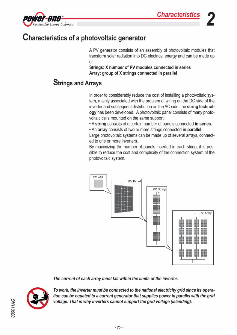
Characteristics of a photovoltaic generatorA PV generator consists of an assembly of photovoltaic modules that transform solar radiation into DC electrical energy and can be made up of: Strings: X number of PV modules connected in seriesArray: group of X strings connected in parallel
Strings and Arrays
In order to considerably reduce the cost of installing a photovoltaic sys-tem, mainly associated with the problem of wiring on the DC side of the inverter and subsequent distribution on the AC side, the string technol-ogy has been developed. A photovoltaic panel consists of many photo-voltaic cells mounted on the same support.• A string consists of a certain number of panels connected in series.• An array consists of two or more strings connected in parallel.Large photovoltaic systems can be made up of several arrays, connect-ed to one or more inverters. By maximizing the number of panels inserted in each string, it is pos-sible to reduce the cost and complexity of the connection system of the photovoltaic system.
The current of each array must fall within the limits of the inverter.
To work, the inverter must be connected to the national electricity grid since its opera-tion can be equated to a current generator that supplies power in parallel with the grid voltage. That is why inverters cannot support the grid voltage (islanding).
Characteristics 2

- 26 -
0000
12BG
Description of the equipmentThis equipment is a multi-string inverter that converts direct electric cur-rent from a photovoltaic generator into alternating electric current and feeds it into the national grid. Photovoltaic panels transform energy from the sun into direct current (DC) electrical energy (through a photovoltaic field, also called photo-voltaic (PV) generator; however, to feed the grid and so that this energy can be used, it has to be transformed into alternating current (AC). This conversion, known as DC to AC inversion, is made efficiently without us-ing rotating parts and only through static electronic devices.In order to allow inverter operation in safe thermal and electrical condi-tions, in the event of adverse environmental conditions or unsuitable in-put voltage values, the unit automatically reduces the value of the power fed into the grid.When used in parallel with the grid, the alternating current generated by the inverter flows directly into the domestic electrical circuit, which is in turn connected, through a distributor, to the national grid.The solar energy system therefore powers all connected electrical de-vices, from lighting to household appliances, etc.When the photovoltaic system is not supplying sufficient power, the power needed to ensure normal operation of the connected electrical devices is drawn from the national grid. If, on the other hand, excess power is produced, this is fed directly into the grid, so becoming avail-able to other consumers.In accordance with local and national regulations, the power produced can be sold to the grid or credited towards future consumption, so bring-ing about a saving of money.
Operating diagram
Characteristics 2
Inverter DistributorPV generator Grid company

- 27 -
0000
12BG
Connection of several inverters together
If the photovoltaic system exceeds the capacity of a single inverter, it is possible to make a multiple connection of inverters to the system, with each one connected to a suitable section of the photovoltaic field, on the DC side, and connected to the grid on the AC side.Each multi-string inverter will work independently of the others and will supply the grid with the maximum power available from its section of photovoltaic panels.
Notes on the sizing of the system
Decisions about how to structure a photovoltaic system depend on a certain number of factors and considerations to make, such as for example, the type of panels, the availability of space, the future location of the system, energy production goals over the long term, etc.
A configuration program that can help to correctly size the photovoltaic system is available on the web site of Power-One (www.power-one.com).
Characteristics 2
- 28 -
0000
13AG
Functionality and components of the equipment
Data transmission and controlThe inverter, or a network of several inverters, can also be monitored remotely through an advanced communication system based on an RS-485 serial interface or a radio module.
RadiomoduleThe radiomodule card is an accessory that is used to replace the RS-485 line for data transmission to the monitoring device.
Analogue inputsExternal analogue sensors for monitoring the environmental conditions (temperature, sunlight, etc.) can be connected to the inverter.The analogue sensors are set directly from the display menus.
Configurable relayThe inverter has a configurable switching relay that can be used in vari-ous operating conditions set in the dedicated menu. A typical application example is the closing of the contact when an alarm occurs.
Remote switching on/offThis control can be used to switch the inverter on/off through an external (remote) control.This function must be enabled in the menu, and if activated, the switch-ing on of the inverter depends on the external switching on/off control as well as being dictated by the presence of the normal parameters that allow the inverter to connect to the grid.
SD cardThis is used for updating the firmware (functionality implemented in a future revision of the firmware).
Feeding reactive power into the gridThe inverter is able to produce reactive power and can therefore feed it into the grid through the setting of the phase shift factor. Feed-in man-agement can be controlled directly by the grid company through a dedi-cated RS485 serial interface.The feed-in management methods vary according to the country of installation and the relevant grid companies. For detailed information about the parameters and characteristics of this function, please contact Power-One directly.
Characteristics 2

- 29 -
0000
14BG
Topographic diagram of the equipment
The diagram shown is a topographic diagram of the operation of the in-verter.The main blocks are the input DC-DC converters (called “boosters”) and the output inverter. Both the DC-DC converters and the output inverter operate at a high switching frequency and so enable a compact size and relatively light weight to be achieved.Each of the input converters is dedicated to a separate array with inde-pendent maximum power point tracking (MPPT) control. This means that the two arrays can be installed with different positions and orientation. Each array is controlled by an MPPT control circuit.The two trackers can be configured (when required) in parallel, to han-dle power and/or current levels higher than those a single tracker can handle.This version of inverter is transformerless, meaning it has no galvanic isolation between input and output, which enables a further increase in conversion efficiency. The inverter is already equipped with all the necessary protective devices for safe operation in compliance with the regulations, even without an isolation transformer.The inverter is controlled by two independent DSPs (Digital Signal Proc-essors) and a central microprocessor. The connection to the electricity grid is therefore controlled by two inde-pendent computers, in full compliance with electrical standards regard-ing system powering and safety.The operating system performs the operation of communicating with the relevant components to carry out data analysis.All this guarantees optimal operation of the entire unit and high efficien-cy in all insolation and load conditions, always in full compliance with the relevant directives, standards and provisions.
Characteristics 2

- 30 -
0000
14BG
Characteristics 2
-S2X
VER
SIO
N
IN1
IN1A
(+)
IN1C
(+)
IN1D
(+)
*IN
1E(+
)
IN1B
(+)
IN1A
(-)
IN1C
(-)
IN1D
(-)
*IN
1E(-
)
IN1B
(-)
IN2
IN2A
(+)
IN2C
(+)
IN2D
(+)
*IN
2E(+
)
IN2B
(+)
IN2A
(-)
IN2C
(-)
IN2D
(-)
*IN
2E(-
)
IN2B
(-)
CU
RREN
TRE
AD
ING
CU
RREN
TRE
AD
ING
OV
PM
ON
ITO
RIN
G
OV
PM
ON
ITO
RIN
G
IN1+ -
MPP
T 1
(DC
/DC
)
IN2+ -
MPP
T 2
(DC
/DC
)
BU
LK C
APS
INV
ERTE
R(D
C/A
C)
LIN
EFI
LTER
DC
/DC
DSP
CO
NTR
.
DC
/AC
DSP
CO
NTR
.
µP
µP
CO
NTR
OL
CIR
CU
IT
GRI
D P
ARA
LLEL
RELA
Y
L1 L2 L3 N PE
-S2
VER
SIO
N
L1L1
, S
L2L2
, S
L3L3
, S
NN
, S
PE
PC_R
S485
+ T
/R
- T/R
GN
D
REM
OTE
CONT
ROL
+ R GN
D
ALA
RM
N.C
N.O
C
PVI-
RAD
IOM
OD
ULE
(OPT
)
PT 1
00
PT 1
000
4...2
0mA
/ 0
...10
V a
dj
4...2
0mA
/ 0
...10
V a
dj
ON
/OFF
EX
T
WIR
ING
BO
X C
IRC
UIT
-S
2X V
ERSI
ON
L1L1
, S
L2L2
, S
L3L3
, S
NN
, S PE
PMU
_RS4
85
+ T
/R
- T/R
GN
D
SDC
ARD
IN1(
+)
IN1(
-)
IN1
IN2
+ - + -
IN2(
+)
IN2(
-) STA
ND
ARD
VER
SIO
N
IN1(
+)
IN1(
-)
IN1
IN2
+ - + -
IN2(
+)
IN2(
-)
-S2
VER
SIO
N
CU
RREN
T RE
AD
ING
OV
P M
ON
ITO
RIN
G
GRI
D S
TAN
DA
RD S
ETTI
NG
SERV
ICE
OR
NO
RMA
L
PC
PMU
AN
1
AN
2
IN M
OD
E
* n
ot
pre
sen
t o
n T
RIO
-20.
0-TL
* an
exp
ansi
on
slo
t fo
r fu
ture
imp
lem
enta
tio
n o
f new
co
mm
un
icat
ion
sys
tem
s is
ava
ilab
le
*03 02

- 31 -
0000
15AG
Protective devices
Anti-Islanding
In the event of a local grid outage by the electricity company, or when the equipment is switched off for maintenance operations, the inverter must be physically disconnected safely, to ensure protection of people work-ing on the grid, all in accordance with the relevant national standards and laws. To prevent possible islanding, the inverter is equipped with an automatic protective disconnection system called “Anti-Islanding”.
Ground fault in the photovoltaic panels
This inverter must be used with panels connected with “floating” con-nections, that is, with positive and negative terminals without ground connections. An advanced ground fault protection circuit continuously monitors the ground connection and disconnects the inverter when a ground fault is detected. The ground fault condition is indicated by a red LED on the front panel.
String fuses
In the S2X versions, string fuses 22 that protect the equipment from currents above the limit value, independently for each string, are pre-in-stalled inside the wiring box 02. The sizing of the fuses must be carefully considered during installation.
Overvoltage surge arresters
As additional protection to prevent damage caused by lightning dischar-ges and electrostatic induction phenomena, DC overvoltage surge arre-sters 15 and AC overvoltage surge arresters 18 are integrated inside the wiring box 02 (S2X versions).
Further protective devices
The inverter is equipped with additional protective devices to guarantee safe operation in any circumstance. These protective devices include:- Continuous monitoring of the grid voltage to ensure the voltage and frequency values stay within operating limits;- Control of internal temperatures to automatically limit the power if nec-essary to ensure the unit does not overheat (derating).
The numerous control devices produce a replete structure to guarantee totally safe operation.
Characteristics 2

- 32 -
0000
16AG
3
Safety instructions and general information The equipment has been manufactured in accordance with the strictest accident-prevention regulations and supplied with safety devices suit-able for the protection of components and operators.
For obvious reasons, it is not possible to anticipate the great number of installations and environments in which the equipment will be installed; it is therefore necessary for the customer to appropriately inform the manufacturer about particular installation conditions.
Power-One accepts no liability for failure to comply with the instructions for correct installation and cannot be held responsible for the systems upstream or downstream of the equipment it has supplied.
It is essential to provide operators with correct information. They must therefore read and comply with the technical information given in the manual and in the attached documentation.
The instructions given in the manual do not replace the safety devices and technical data for installation and operation stuck on the product, and they certainly do not replace the safety regulations in force in the country of installation and common sense rules.The manufacturer is willing to train staff, at its premises or on site, in ac-cordance with conditions to be set out in the contract.
Do not use the equipment if you find any operating anomalies.
Avoid temporary repairs. All repairs should be carried out using only genuine spare parts, which must be installed in accordance with their intended use.
Liabilities arising from commercial components are delegated to their respective manufacturers.
3 - Safety and accident prevention

- 33 -
0000
17AG
Hazardous areas and operations
Environmental conditions and risks
The equipment can be installed outdoors, but only in certain en-vironmental conditions that do not prevent its normal operation. Adverse environmental conditions, such as: sun, rain, snow, wind, too hot or too cold, altitudes, humidity, etc., can lead to a reduction in performance.
Power-One CANNOT be held responsible for disposal of the equip-ment: displays, cables, batteries, accumulators, etc., and therefore the customer must dispose of these substances, which are potentially harm-ful to the environment, in accordance with the regulations in force in the country of installation.
The same precautions should be adopted when scrapping the equipment.
The equipment is not equipped to operate in environments that have particular flam-mability or explosive conditions.
The customer and/or installer must appropriately instruct the operators or anyone who may come near the equipment, and highlight, if neces-sary with notices or other means, the hazardous areas or operations: magnetic fields, hazardous voltages, high temperatures, possibil-ity of discharges, generic hazard, etc...
Signs and plates
The plates attached to the equipment must NOT be removed, damaged, dirtied, hid-den, etc.
The plates must be cleaned regularly and kept visible at all times, and therefore they must NOT be hidden with objects and extraneous parts (rags, boxes, equipment, etc.).The technical data shown in this manual do not in any case replace those shown on the plates attached to the equipment.
Safety and accident prevention 3

- 34 -
0000
17AG
Thermal hazard
WARNING: removal of guards or covers is allowed only 10 minutes after the voltage has been removed; this is to let the components cool down and allow any electrostatic charges and parasitic voltages to be discharged.
When the equipment has just been switched off, it may have hot parts, as a result of overheating of the surfaces at temperature (e.g.: trans-formers, accumulators, coils, etc...) so be careful where you touch.
In the event of fire, use CO2 foam extinguishers and use auto extraction systems to fight fire in closed environments.
Clothing and protective devices for staff
Power-One has eliminated sharp edges and corners, but in some cases it is not possible to do anything, and we therefore advise wearing the clothing and personal protective equipment provided by the employer.
Staff must not wear clothes or accessories that can start fires or generate electrostatic charges or, in general, clothing that can impede personal safety.
All operations on the equipment should be carried out with suitably insu-lated instruments.
Staff must NOT go near the equipment with bare feet or wet hands.
Maintenance operations must be carried out with the equipment discon-nected from the grid.
The maintenance technician must in any case make sure no one else can switch on or operate the equipment during the maintenance opera-tions, and must report any anomaly or damage due to wear or ageing so that the correct safety conditions can be restored.
The installer or maintenance technician must always pay attention to the work environment, so that it is well lit and with sufficient spaces to ensure they have an escape route.
In the installation, consider or make sure the noise emitted based on the environment is not such that it exceeds the thresholds allowed by law (less than 80 dBA).
10 min
Safety and accident prevention 3

- 35 -
0000
18AG
Safety and accident prevention 3Residual Risks
Despite the warnings and safety systems, there are still some residual risks that cannot be eliminated.These risks are listed in the following table with some suggestions for preventing them.
Table of residual risks
RISK ANALYSIS AND DESCRIPTION SUGGESTED REMEDY
Noise pollution due to installation in unsuitable environments or where staff work permanently.
Reassess the environment or the place of installation.
Suitable local ventilation that does not cause overheating of the equip-ment and is sufficient not to create discomfort to people in the room.
Restore suitable ambient condi-tions and air the room.
External weather conditions, such as water seepage, low temperatures, high humidity, etc.
Maintain ambient conditions suit-able for the system.
Overheating of surfaces at temperature (transformers, accumulators, coils, etc. ) can cause burns. Also be careful not to block the cooling slits or systems of the equipment.
Use suitable protective equipment or wait for the parts to cool before switching on the equipment.
Inadequate cleaning: compromises cooling and does not allow the safety plates to be read.
Clean the equipment, plates and work environment adequately.
Accumulation of electrostatic energy can generate hazardous discharges.
Ensure the devices have dis-charged their energy before work-ing on them.
Inadequate training of staff. Ask for a supplementary course.
During installation, temporary fixing can involve risks of unhooking from the bracket 01
Pay attention and prevent access to the installation area.
Accidental disconnection of the quick fit connectors with the equipment in operation, or wrong connections, can generate electric arcs.
Pay attention and prevent access to the installation area.

- 36 -
0000
19AG
General conditions
Transport and handling
Transport of the equipment, especially by road, must be carried out by suitable ways and means for protecting the components (in particular, the electronic components) from violent knocks, humidity, vibration, etc.
During handling, do not make any sudden or fast movements that can create dangerous swinging.
Lifting
Power-One usually stores and protects individual components by suit-able means to make their transport and subsequent handling easier, but as a rule it is necessary to turn to the experience of specialized staff in charge of loading and unloading the components.Where indicated and/or where there is provision, eyebolts or handles, which can be used as anchorage points, are inserted and/or can be inserted.The ropes and means used for lifting must be suitable for bearing the weight of the equipment. Do not lift several units or parts of the equipment at the same time, un-less otherwise indicated.
Unpacking and checking
We remind you that the packaging elements (cardboard, cellophane, staples, adhesive tape, straps, etc.) can cause cuts and other injuries if not handled with care. They should be removed by suitable means and not left in the hands of irresponsible people (e.g. children).The components of the packaging must be disposed of in accord-ance with the regulations in force in the country of installation.When you open the package, check that the equipment is undamaged and make sure all the components are present.If you find any defects or damage, stop unpacking and consult the car-rier, and also promptly inform Power-One.
4
4 - Lifting and transport

- 37 -
0000
20BG
List of supplied components
Table: Components supplied with the equipment
Components available for all models QuantityConnector 21.2500MF/3 2
Connector 21.2500MF/8 4
L-key, TORX TX20 1
Cylinder, TGM58 2
Gasket, 36A3M2025 2
Gland multi-entry seal plug 6mm IP68 light grey TGM613
1
Gasket multi-entry seal neoprene M25 IP68 black 1
Components available for basic and S2 models only QuantityJumpers for configuration of the parallel input chan-nels
2
Components available for the S2X model only QuantityFemale quick fit connectors 8 (20 kW)
10 (27.6 kW)
Male quick fit connectors 8 (20 kW)10 (27.6 kW)
Fuses gPV - 1000V DC - 12 A 16 (20 kW)20 (27.6 kW)
Lifting and transport 4

- 38 -
0000
20BG
Lifting and transport 4Kit of recommended spare parts
A list of spare parts that are compatible with the TRIO inverter and in stock at the Power-One warehouse is given below.
Code Description QuantityTRIO HANDLING KIT Kit of handles and eyebolts for lifting the in-
verter part4 handles 2 eyebolts
KIT 10 FUSES 8A Kit of 8A fuses 10
KIT 10 FUSES 10A Kit of 10A fuses 10
KIT 10 FUSES 12A Kit of 12A fuses 10
KIT 10 FUSES 15A Kit of 15A fuses 10
KIT SURGE DC SIDE TRIO Kit of spare cartridges for DC side surge ar-resters
4 (Dehn PN. 952051) 2 (Dehn PN. 952015)
KIT SURGE AC SIDE TRIO Kit of spare cartridges for AC side surge ar-resters
3 (Dehn PN. 952010) 1 (Dehn PN. 952050)
KIT VDR SIOV DC SIDE TRIO Kit of varistors for DC 4
KIT VDR SIOV AC SIDE TRIO Kit of varistors for AC 4
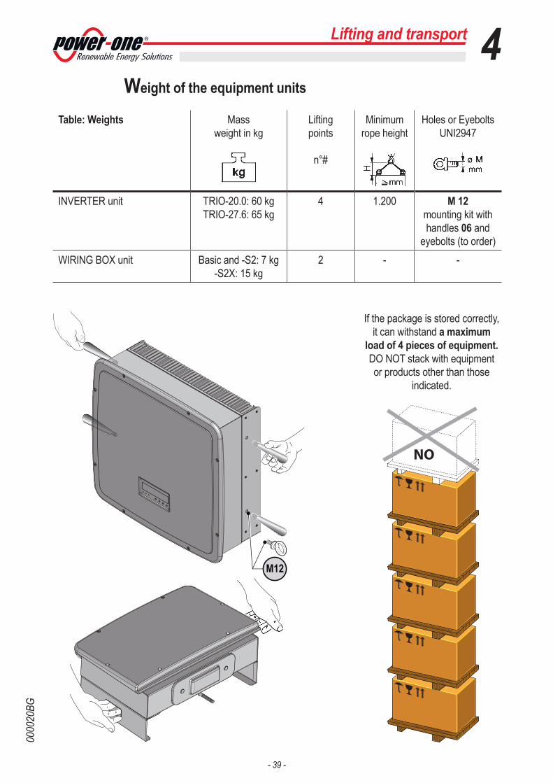
- 39 -
0000
20BG
Lifting and transport 4Weight of the equipment units
Table: Weights Massweight in kg
Lifting points
n°#
Minimum rope height
Holes or Eyebolts UNI2947
INVERTER unit TRIO-20.0: 60 kgTRIO-27.6: 65 kg
4 1.200 M 12mounting kit with handles 06 and
eyebolts (to order)
WIRING BOX unit Basic and -S2: 7 kg-S2X: 15 kg
2 - -
NO
If the package is stored correctly, it can withstand a maximum
load of 4 pieces of equipment. DO NOT stack with equipment or products other than those
indicated.
M12
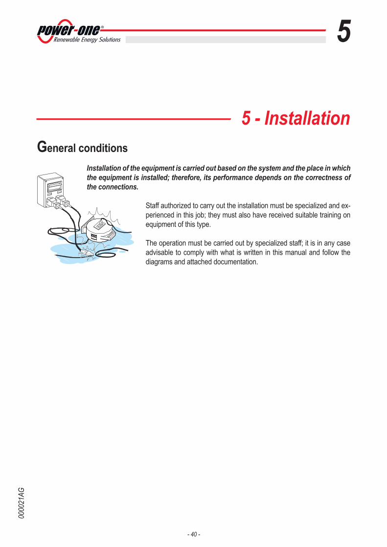
- 40 -
0000
21AG
5
5 - InstallationGeneral conditions
Installation of the equipment is carried out based on the system and the place in which the equipment is installed; therefore, its performance depends on the correctness of the connections.
Staff authorized to carry out the installation must be specialized and ex-perienced in this job; they must also have received suitable training on equipment of this type.
The operation must be carried out by specialized staff; it is in any case advisable to comply with what is written in this manual and follow the diagrams and attached documentation.

- 41 -
0000
22AG
Installation 5The installation must be carried out with the equipment disconnected from the grid (power disconnect switch open) and with the photovoltaic panels shaded or isolated.
Environmental checks
• Consult the technical data to check the environmental parameters to be observed (degree of protection, temperature, humidity, altitude, etc.)• Do not expose to direct sunlight to avoid unwanted power derating due to an increase in the internal temperature of the inverter.• Do not install in small closed rooms where air cannot circulate freely.• To avoid overheating, always make sure the flow of air around the inverter is not blocked.• Do not install in places where gases or flammable substances may be present.• Do not install in rooms where people live or where the prolonged pres-ence of people or animals is expected, because of the noise (about 50dB(A) at 1 m) that the inverter makes during operation.• Avoid electromagnetic interference that can compromise the correct operation of electronic equipment, with consequent situations of danger.
Installations above 2000 metres
On account of the rarefaction of the air (at high altitudes), particular conditions may occur that should be considered when choosing the place of installation:
• Less efficient cooling and therefore a greater likelihood of the device going into derating because of high internal temperatures.• Reduction in the dielectric resistance of the air that, in the presence of high operating voltages (DC input), can create electric arcs (discharges) that can reach the point of damaging the inverter. As the altitude increases, the failure rate of some electronic components increases exponentially because of cosmic radiation.
All installations at altitudes of over 2000 metres must be assessed case by case con-sidering the aforesaid criticalities.
OK OK OKNO
OK OK NO
NO
NO

- 42 -
0000
22AG
Installation position
When choosing the place of installation, comply with the following condi-tions: • Install on a wall or strong structure suitable for bearing the weight.• Install in safe, easy to reach places.• If possible, install at eye-level so that the display and status LEDs can be seen easily.• Install at a height that considers the heaviness of the equipment. If this condition is not complied with, it can create problems in the event of servicing unless suitable means are provided to carry out the operation.• Install vertically with a maximum inclination of +/- 5°. If this condition is not complied with, the inverter could go into temperature derating be-cause of the worsening of heat dissipation.
• To carry out maintenance of the hardware and software of the equip-ment, remove the covers on the front. Check that there are the correct safety distances for the installation that will allow the normal control and maintenance operations to be carried out.• Comply with the indicated minimum distances.
• For a multiple installation, position the inverters side by side.
• If the space available does not allow this arrangement, position the inverters in a staggered arrangement as shown in the figure so that heat dissipation is not affected by other inverters.
OK
OK
NO
NO NO
OK NO
50 cm 50 cm
80 cm
50 cm
Installation 5

- 43 -
0000
23BG
Installation 5Wall mounting• Position the bracket 01 perfectly level on the wall and use it as a drilling template.
• Drill the 10 holes required using a drill with 10mm bit. The holes must be about 70mm deep.
• Fix the bracket to the wall with the 10 wall anchors, 10mm in dia-meter, supplied.
• Hook on the wiring box 02 iby inserting the head of the rear screws in the slots in the bracket, remove the front cover and make all the necessary connections.
N.B. It is not necessary to install the inverter 03 at this stage.
• Unscrew the connector screws 07 and remove the cover 04 so that you can reach the connector between the wiring box and the inverter.Put the cover in the special pocket provided at the back of the wiring box.
• Hook the inverter to the bracket by inserting the head of the rear screws in the slots as shown in the figure. To make lifting easier, handles 06 or eyebolts (M12) can be attached to the side holes pro-vided.
• Working from the bottom of the wiring box, connect the two parts by screwing in the clamp screw 05.
• Once the parts are connected, screw in the two connector screws 07 situated inside the wiring box.
01
0605
03
04
08
04
05
02
07
10 x Ø 10 mm

- 44 -
0000
24AG
Operations preparatory to PV generator connection
Checking the correct polarity of the strings
Using a voltmeter, check that the voltage of each string observes the correct polarity and falls within the input voltage limits accepted by the inverter (see technical data).
If the voltage without load of the string is near the maximum value ac-cepted by the inverter, it must be borne in mind that with low ambient temperatures the string voltage tends to increase (in a different way ac-cording to the photovoltaic module used). In this case, it is necessary to carry out a check of the sizing of the system and/or a check on the connections of the modules of the system (e.g.: number of modules in series higher than the design number).
Checking of leakage to ground of the photovoltaic generator
Measure the voltage present between positive and negative pole of each string with respect to ground.If a voltage is measured between an input pole and ground, it may be that there is a low insulation resistance of the photovoltaic generator and the installer will have to carry out a check to solve the problem.
Do not connect the strings if a leakage to ground has been found because the inverter might not connect to the grid.
Choice of differential protection downstream of the inverter
All Power-One Aurora string inverters marketed in Europe are equipped with a device for protection against ground faults in accordance with the safety standard set in Germany by Standard VDE V 0126-1-1:2006-02 (please refer to section 4.7 of the Standard). In particular, Power-One Aurora inverters are equipped with a redun-dancy on the reading of the ground leakage current sensitive to all components of both direct and alternating current. Measurement of the ground leakage current is carried out at the same time and independ-ently by 2 different processors: it is sufficient for one of the two to detect an anomaly to trip the protection, with consequent separation from the grid and stopping of the conversion process. There is an absolute threshold of 300 mA of total leakage current AC+DC with protection tripping time at a max. of 300 msec.In addition, there are another three tripping levels with thresholds re-spectively at 30 mA/sec, 60 mA/sec and 150 mA/sec to cover the “rapid” changes in fault current induced by accidental contact with leaking live parts. The max. tripping times are progressively shortened as the speed of change in the fault current increases and, starting from the 300 msec/
Installation 5

- 45 -
0000
24AG
max for the 30 mA/sec change, they are shortened respectively to 150 msec and 40 msec for 60 mA and 150 mA changes.It should in any case be noted that the integrated device only protects the system against ground faults that occur upstream of the AC terminals of the inverter (namely towards the DC side of the photovoltaic system and consequently towards the photovoltaic modules). The leakage currents that can occur in the AC section between the draw/feed in point and the inverter are not detected and require an external protection device.For protection of the AC line, on the basis of the aforesaid with regard to the differential protection integrated in Power-One Aurora inverters, it is not necessary to install a type B ground fault interrupter.
In accordance with article 712.413.1.1.1.2 of Section 712 of IEC Standard 64-8/7, we hereby declare that, because of their construction, Power One Aurora inverters do not inject ground fault direct currents.
The use of an AC type circuit breaker with differential thermal magnetic protection with tripping current of 300 mA is advisable so as to prevent false tripping, due to the normal capacitive leakage current of photovoltaic modules.
Installation 5

- 46 -
0000
25BG
Wiring Box componentsFor both models of inverter 03 (20 kW or 27.6 kW), three wiring box 02 are available with different layouts:TRIO-XX.X-TL-OUTD: Basic version wiring boxTRIO-XX.X-TL-OUTD-S2: S2 wiring box version, like the basic version but with AC+DC disconnect switch 14TRIO-XX.X-TL-OUTD-S2X: S2X wiring box version, more complete ver-sion with quick fit connectors, string fuses 22, DC overvoltage surge arresters 15, AC overvoltage surge arresters 18 and AC+DC disconnect switch.
Table: electrical system components
Ref. Description09 communication card10 service cable glands11 DC cable glands12 jumpers13 DC input terminal board14 AC+DC disconnect switch15 DC overvoltage surge arresters16 AC cable gland17 AC output terminal board18 AC overvoltage surge arresters19 Input connectors (MPPT1)20 Input connectors (MPPT2)21 anti-condensation valve22 string fuses
a01 Switch for setting parallel-connected or independent input channelsa05 Rotary switches for setting the country and the language of the display
Installation 5
S2X version
Basic / S2 version
CARDCOM
CARDMEMORY
1
1
10 1614 1711
09
10 161411
1213
21
CARDCOM
CARDMEMORY
1
1
10 1614 1722
10 1614 2119 20
09 15 181213
CARDCOM
CARDMEMORY
1
1
a01a05
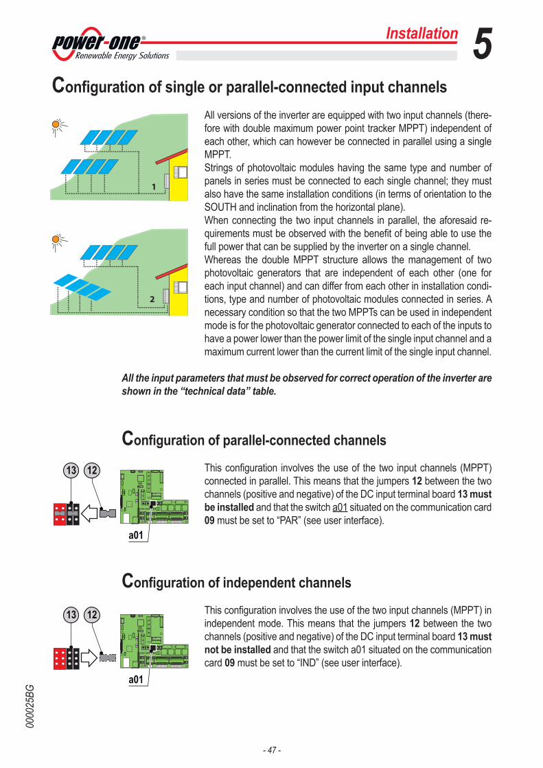
- 47 -
0000
25BG
Installation 5Configuration of single or parallel-connected input channels
All versions of the inverter are equipped with two input channels (there-fore with double maximum power point tracker MPPT) independent of each other, which can however be connected in parallel using a single MPPT. Strings of photovoltaic modules having the same type and number of panels in series must be connected to each single channel; they must also have the same installation conditions (in terms of orientation to the SOUTH and inclination from the horizontal plane).When connecting the two input channels in parallel, the aforesaid re-quirements must be observed with the benefit of being able to use the full power that can be supplied by the inverter on a single channel.Whereas the double MPPT structure allows the management of two photovoltaic generators that are independent of each other (one for each input channel) and can differ from each other in installation condi-tions, type and number of photovoltaic modules connected in series. A necessary condition so that the two MPPTs can be used in independent mode is for the photovoltaic generator connected to each of the inputs to have a power lower than the power limit of the single input channel and a maximum current lower than the current limit of the single input channel.
All the input parameters that must be observed for correct operation of the inverter are shown in the “technical data” table.
Configuration of parallel-connected channels
This configuration involves the use of the two input channels (MPPT) connected in parallel. This means that the jumpers 12 between the two channels (positive and negative) of the DC input terminal board 13 must be installed and that the switch a01 situated on the communication card 09 must be set to “PAR” (see user interface).
Configuration of independent channels
This configuration involves the use of the two input channels (MPPT) in independent mode. This means that the jumpers 12 between the two channels (positive and negative) of the DC input terminal board 13 must not be installed and that the switch a01 situated on the communication card 09 must be set to “IND” (see user interface).
1
2
CARDCOM
CARDMEMORY
1
1
a01
CARDCOM
CARDMEMORY
1
1
a01
1213
1213
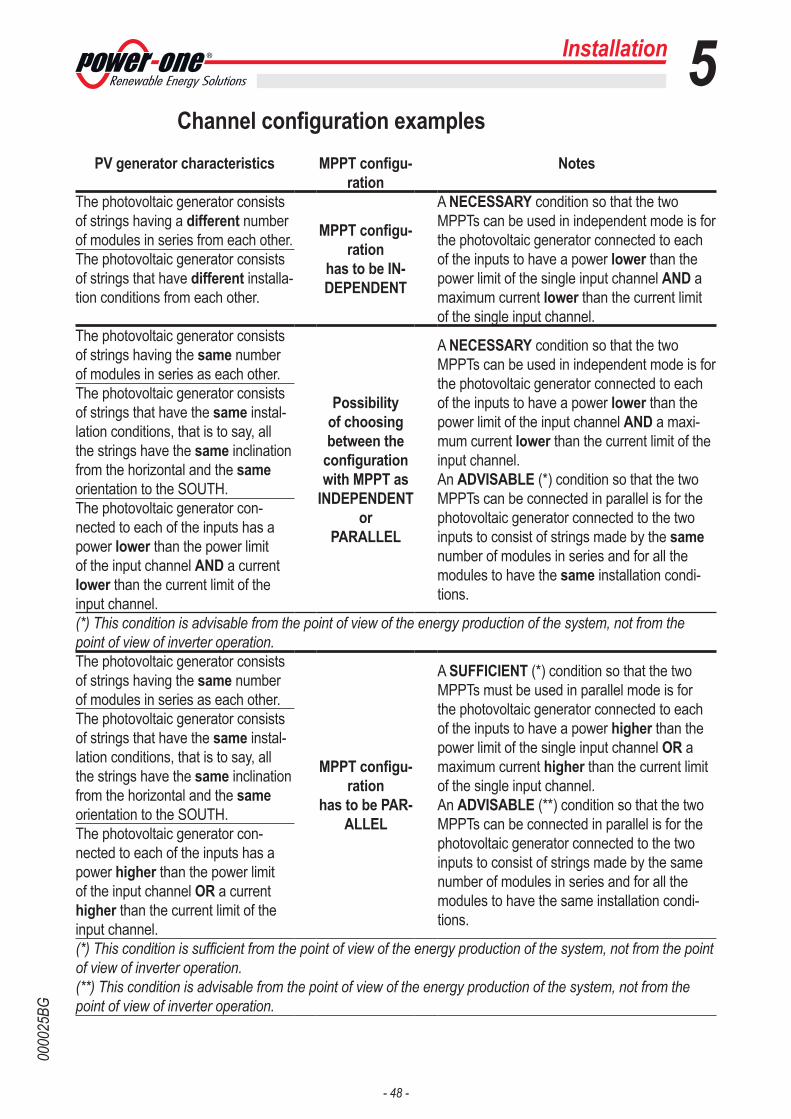
- 48 -
0000
25BG
Channel configuration examplesPV generator characteristics MPPT configu-
rationNotes
The photovoltaic generator consists of strings having a different number of modules in series from each other. MPPT configu-
rationhas to be IN-DEPENDENT
A NECESSARY condition so that the two MPPTs can be used in independent mode is for the photovoltaic generator connected to each of the inputs to have a power lower than the power limit of the single input channel AND a maximum current lower than the current limit of the single input channel.
The photovoltaic generator consists of strings that have different installa-tion conditions from each other.
The photovoltaic generator consists of strings having the same number of modules in series as each other.
Possibility of choosing between the
configuration with MPPT as
INDEPENDENT or
PARALLEL
A NECESSARY condition so that the two MPPTs can be used in independent mode is for the photovoltaic generator connected to each of the inputs to have a power lower than the power limit of the input channel AND a maxi-mum current lower than the current limit of the input channel.An ADVISABLE (*) condition so that the two MPPTs can be connected in parallel is for the photovoltaic generator connected to the two inputs to consist of strings made by the same number of modules in series and for all the modules to have the same installation condi-tions.
The photovoltaic generator consists of strings that have the same instal-lation conditions, that is to say, all the strings have the same inclination from the horizontal and the same orientation to the SOUTH.The photovoltaic generator con-nected to each of the inputs has a power lower than the power limit of the input channel AND a current lower than the current limit of the input channel.(*) This condition is advisable from the point of view of the energy production of the system, not from the point of view of inverter operation.The photovoltaic generator consists of strings having the same number of modules in series as each other.
MPPT configu-ration
has to be PAR-ALLEL
A SUFFICIENT (*) condition so that the two MPPTs must be used in parallel mode is for the photovoltaic generator connected to each of the inputs to have a power higher than the power limit of the single input channel OR a maximum current higher than the current limit of the single input channel.An ADVISABLE (**) condition so that the two MPPTs can be connected in parallel is for the photovoltaic generator connected to the two inputs to consist of strings made by the same number of modules in series and for all the modules to have the same installation condi-tions.
The photovoltaic generator consists of strings that have the same instal-lation conditions, that is to say, all the strings have the same inclination from the horizontal and the same orientation to the SOUTH.The photovoltaic generator con-nected to each of the inputs has a power higher than the power limit of the input channel OR a current higher than the current limit of the input channel.(*) This condition is sufficient from the point of view of the energy production of the system, not from the point of view of inverter operation.(**) This condition is advisable from the point of view of the energy production of the system, not from the point of view of inverter operation.
Installation 5
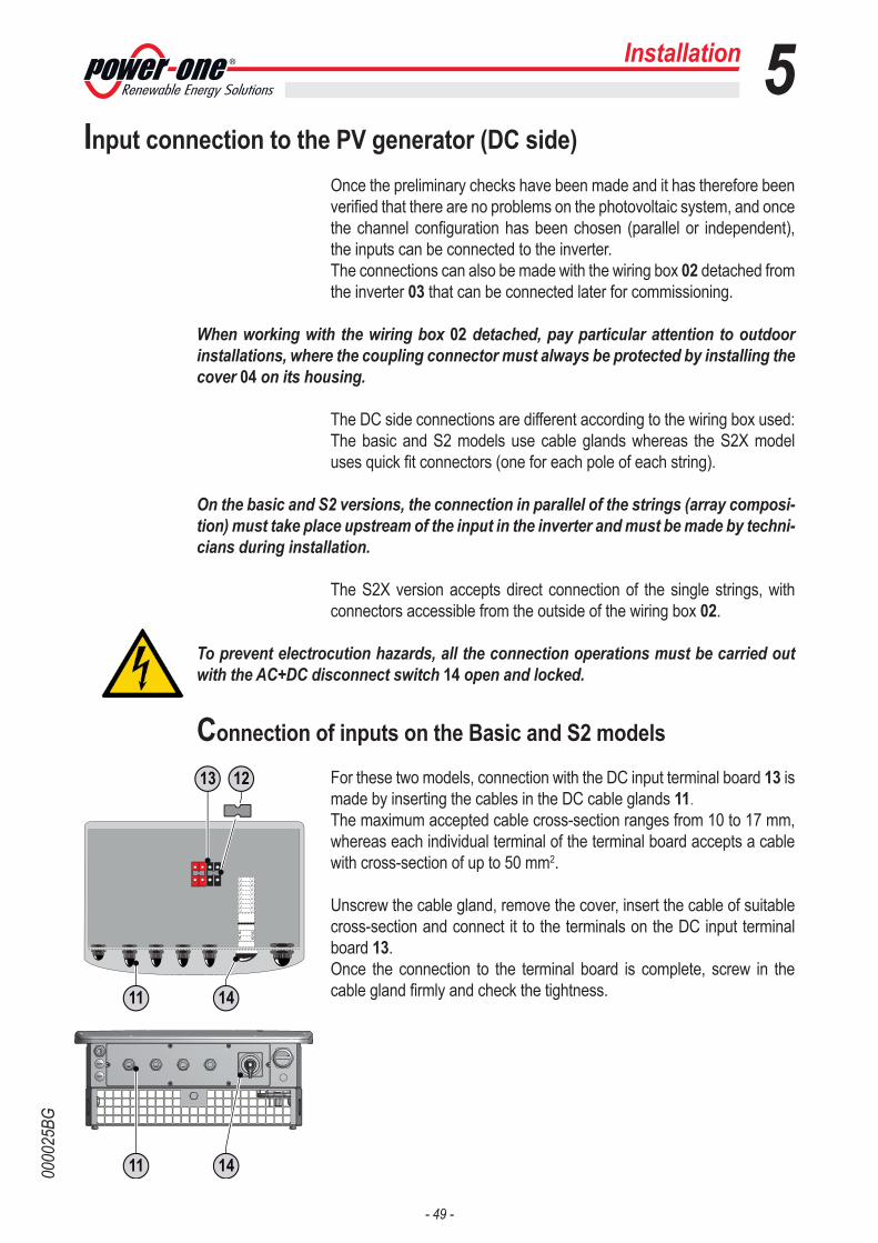
- 49 -
0000
25BG
Installation 5Input connection to the PV generator (DC side)
Once the preliminary checks have been made and it has therefore been verified that there are no problems on the photovoltaic system, and once the channel configuration has been chosen (parallel or independent), the inputs can be connected to the inverter.The connections can also be made with the wiring box 02 detached from the inverter 03 that can be connected later for commissioning.
When working with the wiring box 02 detached, pay particular attention to outdoor installations, where the coupling connector must always be protected by installing the cover 04 on its housing.
The DC side connections are different according to the wiring box used: The basic and S2 models use cable glands whereas the S2X model uses quick fit connectors (one for each pole of each string).
On the basic and S2 versions, the connection in parallel of the strings (array composi-tion) must take place upstream of the input in the inverter and must be made by techni-cians during installation.
The S2X version accepts direct connection of the single strings, with connectors accessible from the outside of the wiring box 02.
To prevent electrocution hazards, all the connection operations must be carried out with the AC+DC disconnect switch 14 open and locked.
Connection of inputs on the Basic and S2 models
For these two models, connection with the DC input terminal board 13 is made by inserting the cables in the DC cable glands 11.The maximum accepted cable cross-section ranges from 10 to 17 mm, whereas each individual terminal of the terminal board accepts a cable with cross-section of up to 50 mm2.
Unscrew the cable gland, remove the cover, insert the cable of suitable cross-section and connect it to the terminals on the DC input terminal board 13.Once the connection to the terminal board is complete, screw in the cable gland firmly and check the tightness.1411
1411
1213

- 50 -
0000
25BG
Installation 5Connection of inputs on the S2X model
For string connections using the S2X wiring box, the quick fit connectors (multicontact or weidmuller) situated at the bottom of the mechanism are used.
For each input channel, there are two groups of connectors:• Input connectors (MPPT1) 19 with codes 1A, 1B, 1C, ...• Input connectors (MPPT2) 20 with codes 2A, 2B, 2C, ...
Connect all the strings included in the design of the system and always check the tightness of the connectors.
If some string inputs are not used, check that there are covers on the connectors and install them if they are missing.This operation is necessary for the tightness of the inverter and to avoid damaging the free connector that could be used at a later date.
In this version of the wiring box, it is NECESSARY not to carry out the paralleling of the strings outside the inverter. This is because the string fuses 22, situated on each input, are not sized to take strings in parallel (array). This operation can cause damage to the fuse and consequently malfunctioning of the inverter.
1422
1419 20
1213

- 51 -
0000
26AG
MULTICONTACT (or equivalent)The installation of Multicontact connectors requires crimping that must be carried out using a suit-able tool.- Strip the end of the cable to which you are going to attach the connector (after making sure it conforms to the limits of the con-nector).- Attach the terminal to the con-ductor using the special crimping pliers.- Insert the cable with terminal into the connector until you hear the click that indicates the terminal is locked inside the connector.- Firmly tighten the cable gland to finish the operation.
Installation 5Procedure for installing quick fit connectors
The quick fit connectors (S2X model only) supplied can be of two different types:
WEIDMULLER The installation of Weidmuller connectors does not require special tools.- Strip the end of the cable to which you are going to attach the connec-tor (after making sure it conforms to the limits of the connector).- Insert the cable in the connector until you hear a locking “click”.- Fully tighten the knurled ring nut for optimum locking.
WARNING: To prevent damage to the equipment, pay particular attention to the pola-rities when wiring the cables.
12 mm
Clik

- 52 -
0000
42AG
Installation 5String protection fuses (S2X models only)
Sizing of fuses
The sizing of the string fuses 22 to be used to protect from “return cur-rents” is very important because it can considerably limit the risk of fire and damage to the PV generator.A “return current” can be generated in the event of a fault and relevant short-circuit at the ends of one or more PV modules of the system; this condition can cause all the current supplied by the strings not involved in the fault, but connected to the same input channel, to pass through the faulty string.
The sizing of the string fuses 22 depends on the technical characteristi-cs of the PV modules making up the PV generator.The value of the correct fuses to be installed is given in the technical data by some suppliers of PV modules.If this information is not available, the correct value can be calculated using the procedure for choosing the fuses.
The value of the chosen fuse must in any case be lower than the maximum return cur-rent indicated in the technical data of the PV module.
Power-One can supply kits of fuses of different values. Please consult the specific section for further information.
22

- 53 -
0000
42AG
Procedure for choosing the fuses
Evaluation of the rated voltage of the fuse
You need to know how many strings are connected in
parallel in the system.
Evaluate the maximum vol-tage that can be reached by
the system.
Choose the fuse that complies with this condition.
It is not necessary to use fuses
Rated voltage of the fuse ≥ Maximum voltage of the systemUn ≥ UMAX
Consider TMIN_P = -25°CYou can find these values in the technical data sheets of
the panels.
Number N strings in parallel N > 3?
UOC_MOD (Voltage without load of the modules)M (number of modules connected in series)
Considerβ=0.4%/°C
NO
NO
NO NO
YES
YES
YESYES
UMAX = UOC_MOD * M * [1 + (TSTC - TMIN_P)*β/100]TSTC = temperature under standard conditions = 25°C
UMAX = M * [UOC_MOD + (TSTC - TMIN_P)*β’/1000]TSTC = temperature under standard conditions = 25°C
Do you know β [%/°C]?
(temperature coefficient for voltage without load)
Do you knowβ’ [mV/°C]?
(temperature coefficient for voltage without load)
Do you know the TMIN_P?
(Minimum working tempe-rature of the panel)
Installation 5

- 54 -
0000
42AG
Evaluation of the capacity of the fuse
Collect the necessary data for choosing the fuse capacity. ISC_MOD (Short-circuit current of the modules)
Do you know IIRREFF?
(Actual maximum irradia-tion expected on the
panels)
Consider IIRREFF = 1200 W/m2
Consider TMAX_P = 70°C
Do you know TMAX_P?
(Maximum working tempera-ture of the panel)
Do you know α [%/°C]?
(temperature coefficient for short-circuit current)
Do you know α’ [mA/°C]?
(temperature coefficient for short-circuit current)
Considerα=0.1 %/°C
You need to define the irra-diation of the installation area
of the system.
You can find these values in the technical data sheets of
the panels = 70°C.
Evaluate the maximum cur-rent generated by the panels.
IMAX = ISC_MOD * [1 + (TMAX_P - TSTC) * α/100] * IIRREFF / IIRRSTCTSTC = temperature under standard conditions = 25°C
IIRRSTC = irradiation under standard conditions = 1000 W/m2
NO
NO
NONO
YES
YES
YES YES
IMAX = [ISC_MOD + (TMAX_P - TSTC) * α’/1000] * IIRREFF / IIRRSTCTSTC = temperature under standard conditions = 25°C
IIRRSTC = irradiation under standard conditions = 1000 W/m2
Installation 5
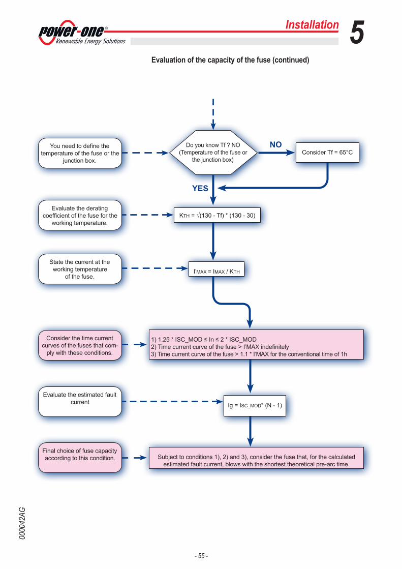
- 55 -
0000
42AG
Evaluation of the capacity of the fuse (continued)
NO
YES
Subject to conditions 1), 2) and 3), consider the fuse that, for the calculated estimated fault current, blows with the shortest theoretical pre-arc time.
1) 1.25 * ISC_MOD ≤ In ≤ 2 * ISC_MOD 2) Time current curve of the fuse > I’MAX indefinitely 3) Time current curve of the fuse > 1.1 * I’MAX for the conventional time of 1h
Consider Tf = 65°CYou need to define the
temperature of the fuse or the junction box.
Do you know Tf ? NO(Temperature of the fuse or
the junction box)
KTH = √(130 - Tf) * (130 - 30)Evaluate the derating
coefficient of the fuse for the working temperature.
I’MAX = IMAX / KTH
State the current at the working temperature
of the fuse.
Ig = ISC_MOD* (N - 1)
Evaluate the estimated fault current
Consider the time current curves of the fuses that com-
ply with these conditions.
Final choice of fuse capacity according to this condition.
Installation 5

- 56 -
0000
27AG
Installation 5Grid output connection (AC side)
For the connection of the inverter to the grid, you can choose between a star connection (3 phases + neutral) and a delta connection (3 phases).In any case, connection of the inverter to ground is mandatory.The cable you use can be 5-pole (star configuration) or 4-pole (delta configuration) and must pass through the AC cable gland 16 to make the connections to the AC output terminal board 17.
The connections can also be made with the wiring box 02 detached from the inverter 03 that can be connected later to be put in service.
When working with the wiring box 02 detached, pay particular attention to outdoor installations, where the coupling connector must always be protected by installing the cover 04 on its housing.
Characteristics and sizing of the line cable
The cross-section of the AC line conductor must be sized in order to prevent unwanted disconnections of the inverter from the grid due to high impedance of the line that connects the inverter to the power supply point; In fact, if the impedance is too high, it causes an increase in the AC voltage that, on reaching the limit set by the country of installation, causes the inverter to switch off.
The table shows the maximum length of the line conductor based on the cross-section of this conductor:
Cross-section of the line con-ductor (mm2)
Maximum length of the line conductor (m)
TRIO-20.0-TL-OUTD TRIO-27.6-TL-OUTD10 42m 30m16 70m 50m25 100m 78m35 138m 98m
The values are calculated considering an energy loss along the line (in rated power conditions) not exceeding 1%.
max 35 mm
20 ÷ 32 mm
2
1614 17

- 57 -
0000
27AG
Load protection switch (AC disconnect switch)
To protect the AC connection line of the inverter, we recommend install-ing a device for protection against over current and leakage with the following characteristics:
TRIO-20.0-TL-OUTD TRIO-27.6-TL-OUTDType Automatic circuit breaker with differential thermal magnetic protection
Voltage/Current rating 40A/400V 63A/400VMagnetic protection characteristic B/C B/C
Type of differential protection A/AC A/ACDifferential sensitivity 300mA 300mA
Number of poles 3/4 3/4
Connection to the AC side terminal board
To prevent electrocution hazards, all the connection operations must be carried out with the disconnect switch downstream of the inverter (grid side) open and locked.
For all models, connection with the AC output terminal board 17 is made by inserting the cables in the AC cable gland 16.The maximum accepted cable cross-section ranges from 20 to 32 mm, whereas each individual terminal of the terminal board accepts a cable with cross-section of up to 35 mm2.Unscrew the cable gland, remove the cover, insert the cable of suitable cross-section and connect the conductors (Neutral, R, S, T and Ground) to the terminals on the AC output terminal board 17.The connection of the inverter to the grid can be with three wires (delta configuration) or with four wires (star configuration).Be careful not to change round one of the phases with neutral!Once the connection to the terminal board is complete, screw in the cable gland firmly and check the tightness.
Before connecting the inverter to the national grid, the standard of the country must be set. To do this, turn the two rotary switches a05 following the table shown in the relevant chapter.
Installation 5
17
R S T TerraNeutro
CARDCOM
CARDMEMORY
1
1
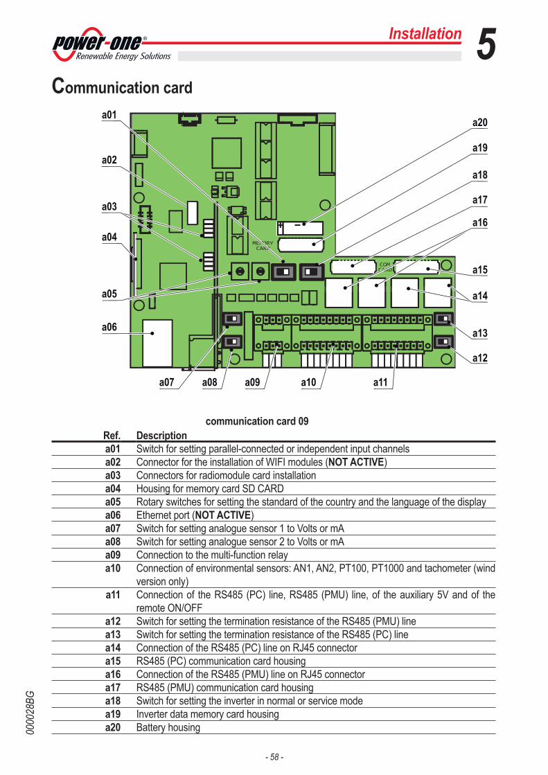
- 58 -
0000
28BG
Installation 5Communication card
communication card 09Ref. Descriptiona01 Switch for setting parallel-connected or independent input channelsa02 Connector for the installation of WIFI modules (NOT ACTIVE)a03 Connectors for radiomodule card installationa04 Housing for memory card SD CARDa05 Rotary switches for setting the standard of the country and the language of the displaya06 Ethernet port (NOT ACTIVE)a07 Switch for setting analogue sensor 1 to Volts or mAa08 Switch for setting analogue sensor 2 to Volts or mAa09 Connection to the multi-function relaya10 Connection of environmental sensors: AN1, AN2, PT100, PT1000 and tachometer (wind
version only)a11 Connection of the RS485 (PC) line, RS485 (PMU) line, of the auxiliary 5V and of the
remote ON/OFFa12 Switch for setting the termination resistance of the RS485 (PMU) linea13 Switch for setting the termination resistance of the RS485 (PC) linea14 Connection of the RS485 (PC) line on RJ45 connectora15 RS485 (PC) communication card housinga16 Connection of the RS485 (PMU) line on RJ45 connectora17 RS485 (PMU) communication card housinga18 Switch for setting the inverter in normal or service modea19 Inverter data memory card housinga20 Battery housing
CARDCOM
CARDMEMORY
1
1a01
a02
a03
a04
a05
a06
a08 a09 a10 a11a07
a12
a13
a14
a15
a16
a17
a18
a19
a20
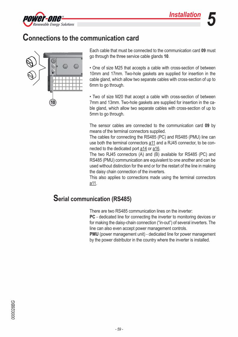
- 59 -
0000
28BG
Connections to the communication cardEach cable that must be connected to the communication card 09 must go through the three service cable glands 10.
• One of size M25 that accepts a cable with cross-section of between 10mm and 17mm. Two-hole gaskets are supplied for insertion in the cable gland, which allow two separate cables with cross-section of up to 6mm to go through.
• Two of size M20 that accept a cable with cross-section of between 7mm and 13mm. Two-hole gaskets are supplied for insertion in the ca-ble gland, which allow two separate cables with cross-section of up to 5mm to go through.
The sensor cables are connected to the communication card 09 by means of the terminal connectors supplied.The cables for connecting the RS485 (PC) and RS485 (PMU) line can use both the terminal connectors a11 and a RJ45 connector, to be con-nected to the dedicated port a14 or a16.The two RJ45 connectors (A) and (B) available for RS485 (PC) and RS485 (PMU) communication are equivalent to one another and can be used without distinction for the end or for the restart of the line in making the daisy chain connection of the inverters.This also applies to connections made using the terminal connectors a11.
Serial communication (RS485)
There are two RS485 communication lines on the inverter:PC - dedicated line for connecting the inverter to monitoring devices or for making the daisy-chain connection (“in-out”) of several inverters. The line can also even accept power management controls.PMU (power management unit) - dedicated line for power management by the power distributor in the country where the inverter is installed.
Installation 5
10
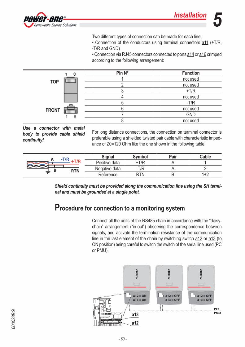
- 60 -
0000
28BG
Installation 5Two different types of connection can be made for each line:• Connection of the conductors using terminal connectors a11 (+T/R, -T/R and GND) • Connection via RJ45 connectors connected to ports a14 or a16 crimped according to the following arrangement:
TOP
FRONT
Pin N° Function1 not used2 not used3 +T/R4 not used5 -T/R6 not used7 GND8 not used
For long distance connections, the connection on terminal connector is preferable using a shielded twisted pair cable with characteristic imped-ance of Z0=120 Ohm like the one shown in the following table:
Signal Symbol Pair Cable Positive data +T/R A 1 Negative data -T/R A 2
Reference RTN B 1+2
Shield continuity must be provided along the communication line using the SH termi-nal and must be grounded at a single point.
Procedure for connection to a monitoring system Connect all the units of the RS485 chain in accordance with the “daisy-chain” arrangement (“in-out”) observing the correspondence between signals, and activate the termination resistance of the communication line in the last element of the chain by switching switch a12 or a13 (to ON position) being careful to switch the switch of the serial line used (PC or PMU).
-T/R +T/R
RTN
A
B
Use a connector with metal body to provide cable shield continuity!
a12 = ONa13 = ON
CARDCOM
CARDMEMORY
1
1
a12 = OFFa13 = OFF
PC/PMU
a12 = OFFa13 = OFF
a13a12

- 61 -
0000
28BG
Installation 5If a single inverter is connected to the monitoring system, activate the termination resistance of the communication line by switching switch a12 or a13 (to ON position).Set a different RS485 address on each inverter of the chain. No inverter should have “Auto” as its address. An address can be chosen freely from out of 2 to 63.The address on the inverter is set through the display and the push-button panel (see relevant chapter).
We recommend not exceeding a length of 1000m for the communication line.No more than 62 inverters can be connected to the same RS485 line.
When using an RS-485 connection, if one or more inverters are added later to the system, you must remember to return to OFF position the switch of the termination resistance used (PC or PMU) of the inverter that was previously the last one of the system.Each inverter is dispatched with two (2) as the predefined RS485 ad-dress and with switch for setting termination resistance a12 or a13 to OFF position.
Monitoring system via serial (RS485)
The RS485 line can be connected to various monitoring devices that can be in local or remote mode:• Local monitoring from PC with PVI-USB-RS485_232 adaptor and Aurora Communicator software• Local monitoring from remote display with PVI-DESKTOP device • Remote monitoring with PVI-AEC-EVO monitoring system and Portal P1For local monitoring, Power-One recommends connecting its PVI-USB-RS485_232 adaptor between the first unit of the daisy-chain and the computer.
Equivalent devices found on the market can also be used for the same purpose, but, bearing in mind that they have never been specifically tested, Power-One cannot guar-antee correct operation of the connection.
Please note that these devices may also require an external termination impedance, whereas this is not necessary with the Aurora PVI-USB-RS485_232.
CARDCOM
CARDMEMORY
1
1
RS485/PMURS485/PC
Gestore rete
PVI-USB-RS485_232PVI-DesktopPVI-AEC-EVO

- 62 -
0000
28BG
Installation 5Monitoring system via Radiomodule
The radiomodule card is an accessory used to replace the RS485 line for data transmission to the monitoring device.
The radiomodule card is installed vertically on the communication card 09 by connecting the two a03 connectors. In turn, wiring ending with an antenna installed outside the wiring box is connected to the radiomod-ule: The part of the wiring box where the antenna will be installed will be in place of one of the service cable glands 10 of size M20.
Monitoring is carried out using PVI-DESKTOP software.
Configurable relay
The inverter has a multi-function relay a09, whose switching can be configured. It can be connected with normally open contact (being con-nected between the NO terminal and the common contact C) and with normally closed contact (being connected between the NC terminal and the common contact C). This contact can be used in four different operating configurations that can be set in the dedicated menu.
Operating modes
• Production: the relay switches whenever a connection to (and there-fore a disconnection from) the grid occurs.So if the NO (or NC) contact is chosen, the contact will stay open (or closed) until the inverter is connected to the grid; once the inverter con-nects to the grid and starts to export power, the relay switches state and therefore closes (or opens).When the inverter disconnects from the grid, the relay contact returns to its position of rest, namely open (or closed).
• Alarm: the relay switches whenever there is an alarm on the inverter (Error). No switching occurs when there is a Warning.So if the NO (or NC) contact is chosen, the contact will stay open (or closed) until the inverter reports an error; once the inverter reports an error, the relay switches state and therefore closes (or opens).The contact remains switched from its rest condition until normal opera-tion is restored.
NC = Normally closedC = Common contactNO = Normally open
CARDCOM
CARDMEMORY
1
1
2
ALARM
NC C
1
NO
6
5
CARDCOM
CARDMEMORY
1
1
2
ALARM
NC C
1
NO
6
5
a09
10

- 63 -
0000
28BG
Installation 5• Alarm (configurable): the relay switches whenever there is an alarm (Error) or a Warning, which have been previously selected by the user through the dedicated menu.If the NO (or NC) contact is chosen, the contact will stay open (or closed) until the inverter reports an error or a warning out of those selected from the menu; once the inverter displays an error or a warning out of those selected, the relay switches state and therefore closes (or opens) the contact. The relay remains switched from its rest condition until the alarm or warning has disappeared.
• Crepuscular: the relay usually switches when the voltage from the photovoltaic generator exceeds/falls below the threshold set for grid connection. If the NO (or NC) contact is chosen, the contact will stay open (or closed) until the inverter has an input voltage higher than the one selected for grid connection. The contact remains switched from its rest condition for as long as the inverter is switched on (even if not connected to the grid). This mode is useful for disconnecting large output transformers that could have unnecessary consumption during the night.
The device to be connected to the relay can be of different types (light, sound, etc) but must comply with the following requirements:
Alternating currentMaximum Voltage: 240 Vac Maximum Current: 1 A
Direct currentMaximum Voltage: 30 Vdc Maximum Current: 0.8 A
Cable requirementsExternal diameter: from 5 to 17 mmConductor cross-section: from 0.14 to 1.5 mm2

- 64 -
0000
28BG
Installation 5Environmental sensors
External sensors for monitoring environmental conditions can be con-nected to the connectors of the environmental sensors a10: AN1 - Analogue sensor 1 connectionAN2 - Analogue sensor 2 connectionPT100 - Connection of a PT100 temperature sensorPT1000 - Connection of a PT1000 temperature sensor
Setting of the connected analogue sensors must be carried out by set-ting the following values in the relevant menu:- GAIN- OFFSET- Unit of measure
For each analogue sensor, AN1 and AN2, it is also necessary to set the switch, a07 or a08, to select whether the reading is in Volts or mA.
Each sensor model has precise configuration values that must be set meticulously. The power supply to the sensors must be installed outside the inverter, according to the manufacturer’s specifications.
Specifications of environmental sensors
Tables with the technical data of the main sensors marketed by Power-One are shown below:
Model Type Gain Offset U.d.M.PVI-AEC-IRR Irradiation sensor 120 0 W/mqPVI-AEC-IRR-T Irradiation sensor with integrated
cell temp. sensorIrradiation: 120Cell temp.: 10.869
Irradiation: 0Cell temp.: -20
Irradiation: W/m2Cell temp.: °C
PVI-AEC-RAD-13TC Irradiation sensor 130 0 W/m2PVI-AEC-RAD-13-TC-T Irradiation sensor with integrated
cell temp. sensorIrradiation: 130Cell temp.: 11.507
Irradiation: 0Cell temp.: -26.1
Irradiation: W/m2Cell temp.: °C
PVI-AEC-CONV-T100 PT100/0...10V converter 15 -50 °C a 0...10VPVI-AEC-T1000-INTEGR Ambient temperature sensor with
integrated converter10 -50 °C
PVI-AEC-WIND-COMPACT Wind speed sensor 5 0 m/sPVI-AEC-PYR-1300 Pyranometer (0...1300W/m2) 65 0 W/m2PVI-AEC-T100-ADH Adhesive PT100 module
temperature sensor (back cell)N/A N/A N/A
PVI-AEC-T1000-BOX PT1000 ambient temperature sensor
N/A N/A N/A
CARDCOM
CARDMEMORY
1
1
a10
CARDCOM
CARDMEMORY
1
1
100RTD31000
PT
RTD3PT
+WTA
CH
-WTA
CH
15
16
100PTRTD21000RTD2PT
100A2
COMA2
RTD1
RTD1PT
1000
PTA1
A1COM
2
1

- 65 -
0000
28BG
Installation 5Model Output signal External power
supplyTRIO 20/27.6 compatibility
EVO compatibility
PVI-AEC-IRR 0...10Vdc YES YES YESPVI-AEC-IRR-T 0...10Vdc YES YES YESPVI-AEC-RAD-13TC 0...10Vdc YES YES YESPVI-AEC-RAD-13-TC-T 0...10Vdc YES YES YESPVI-AEC-CONV-T100 0...10Vdc YES YES YESPVI-AEC-T1000-INTEGR 0...10Vdc YES YES YESPVI-AEC-WIND-COMPACT 0...10Vdc YES YES YESPVI-AEC-PYR-1300 0...20mA YES NO YESPVI-AEC-T100-ADH 3-wire connection on terminals: RTD1PT100
RTD2PT100 RTD3PT100NO YES YES
PVI-AEC-T1000-BOX 3-wire connection on terminals: RTD1PT1000 RTD2PT1000 RTD3PT1000
NO YES YES
Connection diagrams for environmental sensors
Connection diagrams for the main sensors marketed by Power-One are shown below: For non-conventional installations or additional informa-tion about the connections, please contact the technical support depart-ment.
A1/A2 (Wind speed) A1/A2_RTN
+Vcc
-Vcc
Ground
+Vcc_Heat (external)
-Vcc_Heat (external)
RGETNI-0001T-CEA-IVP
+Vcc
A1/A2_RTN-Vcc
A1/A2
HDA-001T-CEA-IVP
N.C.
RTD1PT100(PT_RTN)
(PT_SENSE)
(PT_ALIM)
RTD2PT100
RTD3PT100
)ecnaidarrI(
)erutarepmet(
PVI-AEC-RAD-13-TC-TPVI-AEC-IRR-T
A1
A2
+Vcc
A1/A2_RTN-Vcc
PVI-AEC-RAD-13TC
A1/A2
A1/A2_RTN
+Vcc
-Vcc
PVI-AEC-IRR
RTD1PT1000(PT_RTN)
(PT_SENSE)
(PT_ALIM)
RTD2PT1000
RTD3PT1000
PVI-AEC-T1000-BOX
N.C.
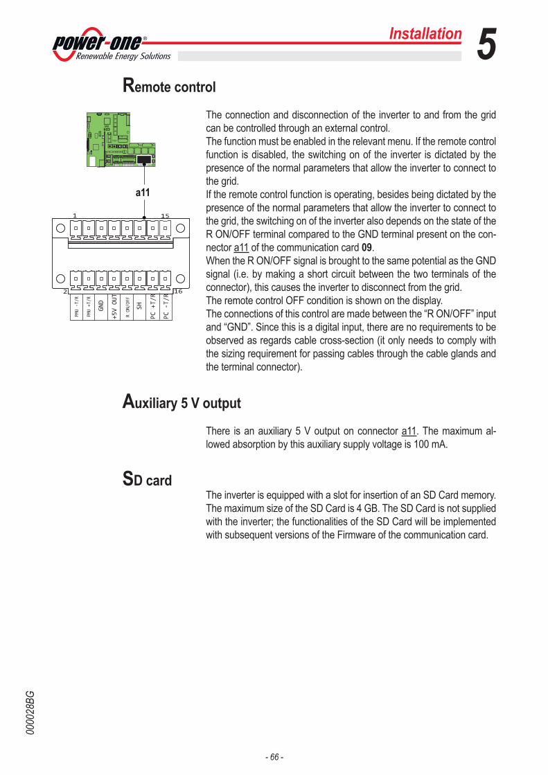
- 66 -
0000
28BG
Remote control The connection and disconnection of the inverter to and from the grid can be controlled through an external control.The function must be enabled in the relevant menu. If the remote control function is disabled, the switching on of the inverter is dictated by the presence of the normal parameters that allow the inverter to connect to the grid.If the remote control function is operating, besides being dictated by the presence of the normal parameters that allow the inverter to connect to the grid, the switching on of the inverter also depends on the state of the R ON/OFF terminal compared to the GND terminal present on the con-nector a11 of the communication card 09.When the R ON/OFF signal is brought to the same potential as the GND signal (i.e. by making a short circuit between the two terminals of the connector), this causes the inverter to disconnect from the grid.The remote control OFF condition is shown on the display.The connections of this control are made between the “R ON/OFF” input and “GND”. Since this is a digital input, there are no requirements to be observed as regards cable cross-section (it only needs to comply with the sizing requirement for passing cables through the cable glands and the terminal connector).
Auxiliary 5 V output
There is an auxiliary 5 V output on connector a11. The maximum al-lowed absorption by this auxiliary supply voltage is 100 mA.
SD cardThe inverter is equipped with a slot for insertion of an SD Card memory. The maximum size of the SD Card is 4 GB. The SD Card is not supplied with the inverter; the functionalities of the SD Card will be implemented with subsequent versions of the Firmware of the communication card.
Installation 5
a11
CARDCOM
CARDMEMORY
1
1
162
PMU+T/R
PMU-T/R
1
GND
RON/OFF
+5VOUT
SH
PC+T/R
PC-T/R
151
1
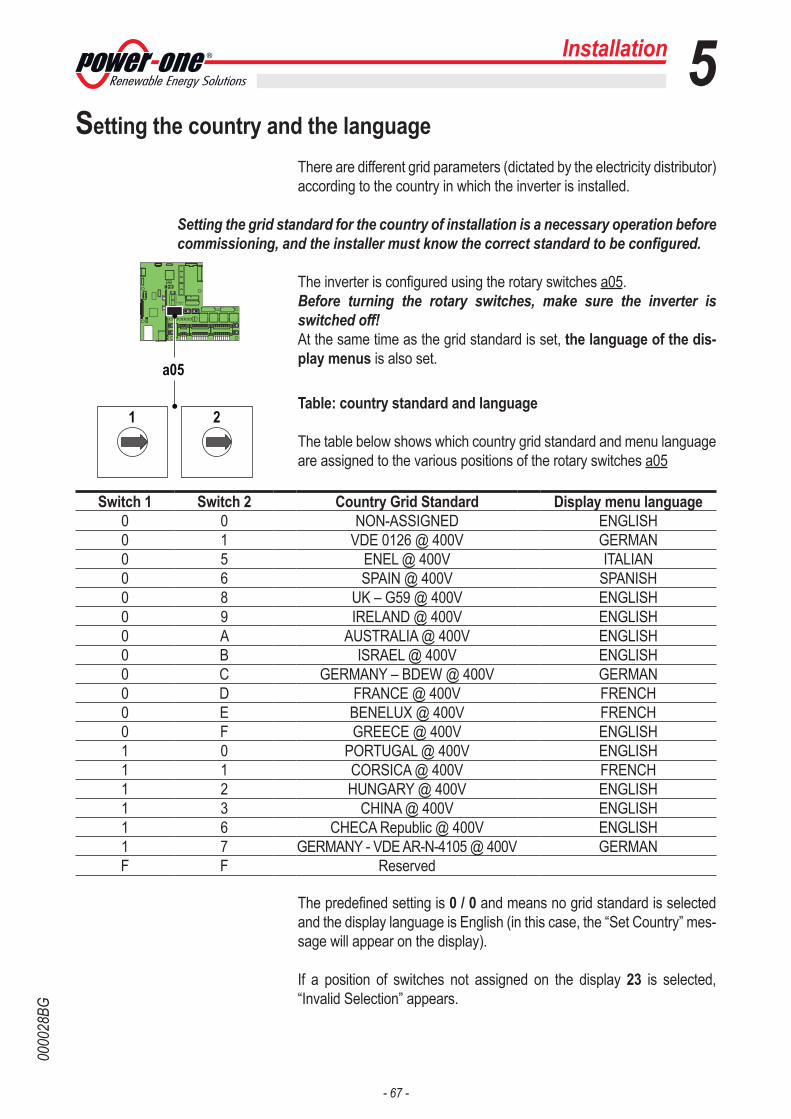
- 67 -
0000
28BG
Installation 5Setting the country and the language
There are different grid parameters (dictated by the electricity distributor) according to the country in which the inverter is installed.
Setting the grid standard for the country of installation is a necessary operation before commissioning, and the installer must know the correct standard to be configured.
The inverter is configured using the rotary switches a05.Before turning the rotary switches, make sure the inverter is switched off! At the same time as the grid standard is set, the language of the dis-play menus is also set.
Table: country standard and language
The table below shows which country grid standard and menu language are assigned to the various positions of the rotary switches a05
Switch 1 Switch 2 Country Grid Standard Display menu language0 0 NON-ASSIGNED ENGLISH0 1 VDE 0126 @ 400V GERMAN0 5 ENEL @ 400V ITALIAN0 6 SPAIN @ 400V SPANISH0 8 UK – G59 @ 400V ENGLISH0 9 IRELAND @ 400V ENGLISH0 A AUSTRALIA @ 400V ENGLISH0 B ISRAEL @ 400V ENGLISH0 C GERMANY – BDEW @ 400V GERMAN0 D FRANCE @ 400V FRENCH0 E BENELUX @ 400V FRENCH0 F GREECE @ 400V ENGLISH1 0 PORTUGAL @ 400V ENGLISH1 1 CORSICA @ 400V FRENCH1 2 HUNGARY @ 400V ENGLISH1 3 CHINA @ 400V ENGLISH1 6 CHECA Republic @ 400V ENGLISH1 7 GERMANY - VDE AR-N-4105 @ 400V GERMANF F Reserved
The predefined setting is 0 / 0 and means no grid standard is selected and the display language is English (in this case, the “Set Country” mes-sage will appear on the display).
If a position of switches not assigned on the display 23 is selected, “Invalid Selection” appears.
CARDCOM
CARDMEMORY
1
1
a05
1 2

- 68 -
0000
28BG
Saving the country standard and language
The settings become fixed after 24 hours of operation of the inverter (it does not need to be connected to the grid, and only needs to be pow-ered).The time remaining before the settings become fixed can be seen in the dedicated menu, and a notice appears if the time has expired.
Once the settings are fixed, turning the rotary switches will produce no effect. In this condition, only the language can be changed through the dedicated menu.
At any time and for any reason, the ENGLISH language of the display menu can be set by simultaneously pressing the “ESC” and “ENTER” buttons for at least 3 seconds.
If it is necessary to change the standard of the country after the settings have been fixed (after 24 hours of operation) please contact Power-One’s technical support de-partment with the part number and serial number of the inverter to hand.
Installation 5

- 69 -
0000
29AG
General conditions One of the first rules for preventing damage to the equipment and to the operator is to have a thorough knowledge of the INSTRUMENTS. We therefore advise you to read this manual carefully. If you are not sure about anything or there is discordance of information, please ask for more detailed information.
Do not use the equipment if:- you do not have suitable qualifications to work on this equipment or similar products;- you are unable to understand how it works;- you are not sure what will happen when the buttons or switches are operated;- you notice any operating anomalies;- there are doubts or contradictions between your experience, the manual and/or other operators.
Power-One cannot be held responsible for damage to the equipment or the operator if caused by incompetence, insufficient qualifications or lack of training.
6
6 - Instruments
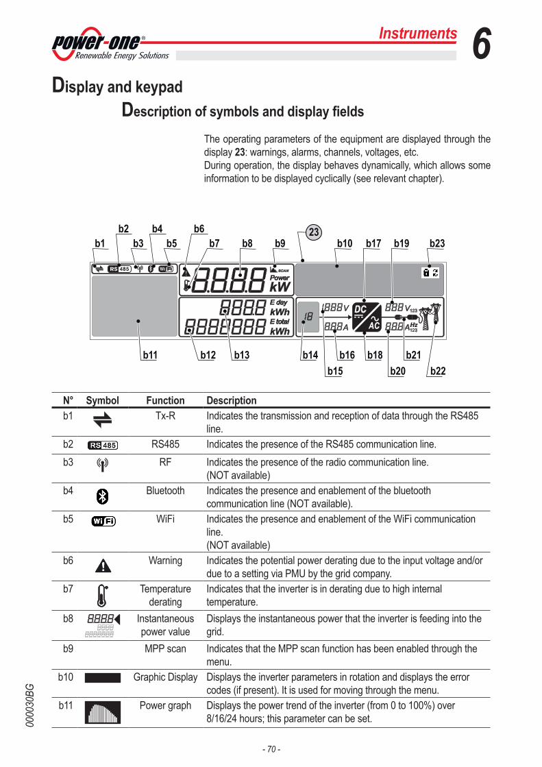
- 70 -
0000
30BG
Instruments 6
N° Symbol Function Descriptionb1 Tx-R Indicates the transmission and reception of data through the RS485
line.b2 RS485 Indicates the presence of the RS485 communication line.b3 RF Indicates the presence of the radio communication line.
(NOT available)b4 Bluetooth Indicates the presence and enablement of the bluetooth
communication line (NOT available).b5 WiFi Indicates the presence and enablement of the WiFi communication
line.(NOT available)
b6
Warning Indicates the potential power derating due to the input voltage and/or due to a setting via PMU by the grid company.
b7 Temperature derating
Indicates that the inverter is in derating due to high internal temperature.
b8 Instantaneous power value
Displays the instantaneous power that the inverter is feeding into the grid.
b9 MPP scan Indicates that the MPP scan function has been enabled through the menu.
b10 Graphic Display Displays the inverter parameters in rotation and displays the error codes (if present). It is used for moving through the menu.
b11 Power graph Displays the power trend of the inverter (from 0 to 100%) over 8/16/24 hours; this parameter can be set.
Display and keypadDescription of symbols and display fields
The operating parameters of the equipment are displayed through the display 23: warnings, alarms, channels, voltages, etc.During operation, the display behaves dynamically, which allows some information to be displayed cyclically (see relevant chapter).
DCAC
23b1 b9 b17 b19b8b3
b4 b6
b11 b13 b14 b16 b18b15
b21b20 b22
b12
b5 b7b2
b23b10

- 71 -
0000
30BG
N° Symbol Function Descriptionb12 Total Energy
ValueDisplays the total energy produced since installation of the inverter.
b13 Daily energy value
Displays the energy produced over a day.
b14 Photovoltaic generator
Indicates that the PV generator voltage is higher than the Vstart of the inverter. The indicated number represents the string or channel of which the voltage and current are displayed (in the case of channels in parallel, 1 is always displayed).
b15 DC voltage value
Displays the direct voltage from the input channel of the photovoltaic generator.
b16 DC current value
Displays the direct current from the input channel of the photovoltaic generator.
b17 DC DC/DC circuit part
Indicates the DC/DC input circuit part (Booster)
b18 DC/AC circuit part
Indicates the circuit part for conversion from DC to AC.
b19 123 AC voltage value
Displays the reading of the grid voltage (alternating voltage).The number at the side indicates the phase of which the AC voltage value is displayed.
b20123
AC current value
Displays the reading of the current or frequency that is fed into the grid (alternating voltage). The number at the side indicates the phase 1, 2 or 3 of which the AC current value is displayed.
b21 Connection to the grid
These are displayed in sequence during connection to the grid. The icon depicts a plugged-in plug if connected to the grid, and an unplugged plug if disconnected from the grid.
b22 Grid status This icon can indicate three AC voltage states:Icon not present: no grid voltageFlashing icon: grid voltage present but outside the parameters set by the grid standardIcon present: grid voltage present and within the parameters set by the grid standard
b23 Cyclic display activated/
deactivated
At the top right of the graphic display b10, a padlock or two arrows will be displayed depending on whether the display of data on the display b10 is locked (padlock) or cyclic (arrows).
6Instruments
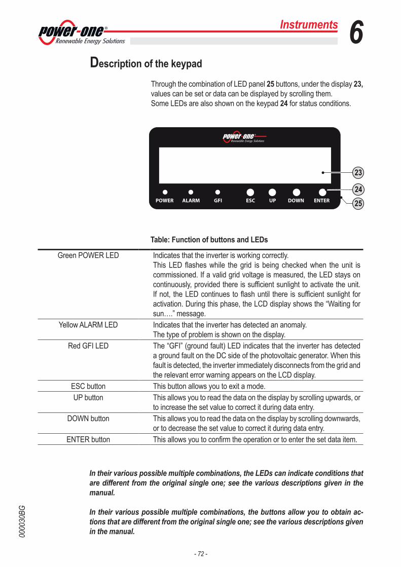
- 72 -
0000
30BG
Description of the keypad
Through the combination of LED panel 25 buttons, under the display 23, values can be set or data can be displayed by scrolling them.Some LEDs are also shown on the keypad 24 for status conditions.
6Instruments
Green POWER LED Indicates that the inverter is working correctly.This LED flashes while the grid is being checked when the unit is commissioned. If a valid grid voltage is measured, the LED stays on continuously, provided there is sufficient sunlight to activate the unit. If not, the LED continues to flash until there is sufficient sunlight for activation. During this phase, the LCD display shows the “Waiting for sun….” message.
Yellow ALARM LED Indicates that the inverter has detected an anomaly. The type of problem is shown on the display.
Red GFI LED The “GFI” (ground fault) LED indicates that the inverter has detected a ground fault on the DC side of the photovoltaic generator. When this fault is detected, the inverter immediately disconnects from the grid and the relevant error warning appears on the LCD display.
ESC button This button allows you to exit a mode.UP button This allows you to read the data on the display by scrolling upwards, or
to increase the set value to correct it during data entry.DOWN button This allows you to read the data on the display by scrolling downwards,
or to decrease the set value to correct it during data entry.ENTER button This allows you to confirm the operation or to enter the set data item.
Table: Function of buttons and LEDs
In their various possible multiple combinations, the LEDs can indicate conditions that are different from the original single one; see the various descriptions given in the manual.
In their various possible multiple combinations, the buttons allow you to obtain ac-tions that are different from the original single one; see the various descriptions given in the manual.
POWER ALARM GFI ESC UP DOWN ENTER
23
2524

- 73 -
0000
31AG
7
General conditions Before checking the operation of the equipment, it is necessary to have a thorough knowledge of the INSTRUMENTS chapter and the functions that have been enabled in the installation.The equipment operates automatically without the aid of an operator; operating state is controlled through the instruments.
The interpretation or variation of some data is reserved exclusively for specialized and qualified staff.
The incoming voltage must not exceed the maximum values shown in the technical data in order to prevent damage to the equipment. Consult the technical data for further details.
Even during operation, check that the environmental and logistic condi-tions are correct (see installation chapter). Make sure that the said conditions have not changed over time and that the equipment is not exposed to adverse weather conditions and has not been isolated with foreign bodies.
7 - Operation
- 74 -
0000
32BG
Monitoring and data transmissionAs a rule, the inverter operates automatically and does not require spe-cial checks. When there is not enough solar radiation to supply power for export to the grid, (e.g. during the night) it disconnects automatically and goes into stand-by mode. The operating cycle is automatically restored when there is sufficient solar radiation. At this point, the luminous LEDs on the LED panel 25 will indicate this state.
User interface mode
The inverter is able to provide information about its operation through the following instruments:• Warning lights (luminous LEDs)• LCD display for displaying operating data• Data transmission on dedicated RS-485 serial line. The data can be collected by a PC or a data logger equipped with an RS-485 port.If the RS-485 line is used, it may be advisable to use the RS-485/RS232 serial interface converter or a data logger. If you have any doubts about the compatibility of the devices, please contact Power-One’s technical support department.
Types of data available
The inverter provides two types of data, which are usable through the relevant interface software and/or through the display 23.
Real-time operating dataReal-time operating data can be transmitted on request through the communication lines and are not recorded in the inverter. For data trans-mission to a PC, the free software supplied with the inverter can be used (please check at www.power-one.com for more updated versions). Internally stored dataThe inverter internally stores a set of data that are necessary for process-ing statistical data and an error log with time marking.
Operation 7
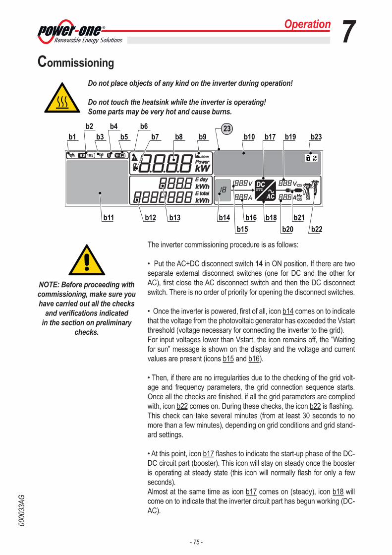
- 75 -
0000
33AG
Operation 7Commissioning
Do not place objects of any kind on the inverter during operation!
Do not touch the heatsink while the inverter is operating!Some parts may be very hot and cause burns.
The inverter commissioning procedure is as follows:
• Put the AC+DC disconnect switch 14 in ON position. If there are two separate external disconnect switches (one for DC and the other for AC), first close the AC disconnect switch and then the DC disconnect switch. There is no order of priority for opening the disconnect switches.
• Once the inverter is powered, first of all, icon b14 comes on to indicate that the voltage from the photovoltaic generator has exceeded the Vstart threshold (voltage necessary for connecting the inverter to the grid). For input voltages lower than Vstart, the icon remains off, the “Waiting for sun” message is shown on the display and the voltage and current values are present (icons b15 and b16).
• Then, if there are no irregularities due to the checking of the grid volt-age and frequency parameters, the grid connection sequence starts. Once all the checks are finished, if all the grid parameters are complied with, icon b22 comes on. During these checks, the icon b22 is flashing.This check can take several minutes (from at least 30 seconds to no more than a few minutes), depending on grid conditions and grid stand-ard settings.
• At this point, icon b17 flashes to indicate the start-up phase of the DC-DC circuit part (booster). This icon will stay on steady once the booster is operating at steady state (this icon will normally flash for only a few seconds).Almost at the same time as icon b17 comes on (steady), icon b18 will come on to indicate that the inverter circuit part has begun working (DC-AC).
DCAC
23b1 b9 b17 b19b8b3
b4 b6
b11 b13 b14 b16 b18b15
b21b20 b22
b12
b5 b7b2
b23b10
NOTE: Before proceeding with commissioning, make sure you have carried out all the checks
and verifications indicated in the section on preliminary
checks.

- 76 -
0000
33AG
• Immediately after this, the procedure of connection to the grid will start, during which icon b21 will come on and the icons on the line will be dis-played in sequence until the inverter is connected. After the inverter is connected, the icons on the whole line b21 will come on steady.If the inverter disconnects from the grid, the icons of the left side (cable and plug) of the line b21 will stay on.
• Once the connection sequence has been completed, the inverter starts to operate and indicates its correct operation by making a sound and by the green LED coming on steady on the LED panel 25. This means there is sufficient solar radiation to feed power into the grid.
• If the checking of the grid does not give a positive result, the unit will repeat the procedure until all the parameters that allow connection to the grid (grid voltage and frequency, insulation resistance) are within the range. During this procedure, the green LED flashes.
At the end of the first starting of the inverter, the wiring box must be configured using the dedicated Aurora Manager software. The software and relevant manual for carry-ing out this configuration are contained in the CD supplied with the inverter.
Operation 7

- 77 -
0000
33AG
Dynamic behaviour of the display
• If the MPPT scan function is enabled, icon b9 will be shown on the display. See configuration in the MPPT settings menu section. This icon will flash during scanning.
• During operation, the following values are displayed in rotation:- Voltage and current (b15 and b16) from the PV generator. According to the configuration or model of the inverter, the voltages and currents of one or both channels (or of the single strings) will be displayed. The input channel considered is indicated by the value entered on icon b14.- Voltage and current (b19 and b20) on the various phases. According to the model of inverter, the voltages and currents of one (1) or three phases (1,2,3) will be displayed. The phase considered is shown on the right side of the voltage and current values. At the end of the aforesaid display, the grid frequency will be indicated in field b20 and the line voltage will be indicated in field b19.At the same time, the main readings made by the inverter will be dis-played in rotation on the graphic display b10.
• Display of the power graph b11The histogram includes 16 horizontal units and 20 vertical units.The period of time is represented by the horizontal axis of the graph and can be set by the user to 8, 16 or 24 hours; therefore, each horizontal unit can represent 30, 60 or 120 minutes.The vertical axis represents the maximum power derating (30 kW for the TRIO-27.6 and 22 kW for the TRIO-20) and therefore 100% correspon-ds to this outgoing exported power value.Finally, bear in mind that the power value expressed by each column of the graph represents the average value of the power during the period relating to the horizontal unit.
• If the icons b21 on the left side (cable and plug) stay on with the as-sembled plug off, it means the inverter is disconnected from the grid; if the icons of the assembled plug and the pylons are on, it means the grid “is good” for connection.
Operation 7
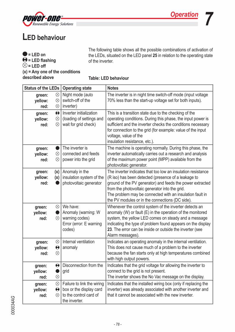
- 78 -
0000
34AG
LED behaviourThe following table shows all the possible combinations of activation of the LEDs, situated on the LED panel 25 in relation to the operating state of the inverter.
Table: LED behaviour
= LED on = LED flashing = LED off
(x) = Any one of the conditions described above
Operation 7
Status of the LEDs Operating state Notesgreen:
yellow: red:
Night mode (auto switch-off of the inverter)
The inverter is in night time switch-off mode (input voltage 70% less than the start-up voltage set for both inputs).
green: yellow:
red:
Inverter initialization (loading of settings and wait for grid check)
This is a transition state due to the checking of the operating conditions. During this phase, the input power is sufficient and the inverter checks the conditions necessary for connection to the grid (for example: value of the input voltage, value of the insulation resistance, etc.).
green: yellow:
red:
The inverter is connected and feeds power into the grid
The machine is operating normally. During this phase, the inverter automatically carries out a research and analysis of the maximum power point (MPP) available from the photovoltaic generator.
green: (x)yellow: (x)
red:
Anomaly in the insulation system of the photovoltaic generator
The inverter indicates that too low an insulation resistance (R iso) has been detected (presence of a leakage to ground of the PV generator) and feeds the power extracted from the photovoltaic generator into the grid. The problem may be connected with an insulation fault in the PV modules or in the connections (DC side).
green: yellow:
red:
We have:Anomaly (warning: W warning codes)Error (error: E warning codes)
Whenever the control system of the inverter detects an anomaly (W) or fault (E) in the operation of the monitored system, the yellow LED comes on steady and a message indicating the type of problem found appears on the display 23. The error can be inside or outside the inverter (see Alarm messages).
green: yellow:
red:
Internal ventilation anomaly
Indicates an operating anomaly in the internal ventilation. This does not cause much of a problem to the inverter because the fan starts only at high temperatures combined with high output powers.
green: yellow:
red:
Disconnection from the grid
Indicates that the grid voltage for allowing the inverter to connect to the grid is not present. The inverter shows the No Vac message on the display.
green: yellow:
red:
Failure to link the wiring box or the display card to the control card of the inverter.
Indicates that the installed wiring box (only if replacing the inverter) was already associated with another inverter and that it cannot be associated with the new inverter.
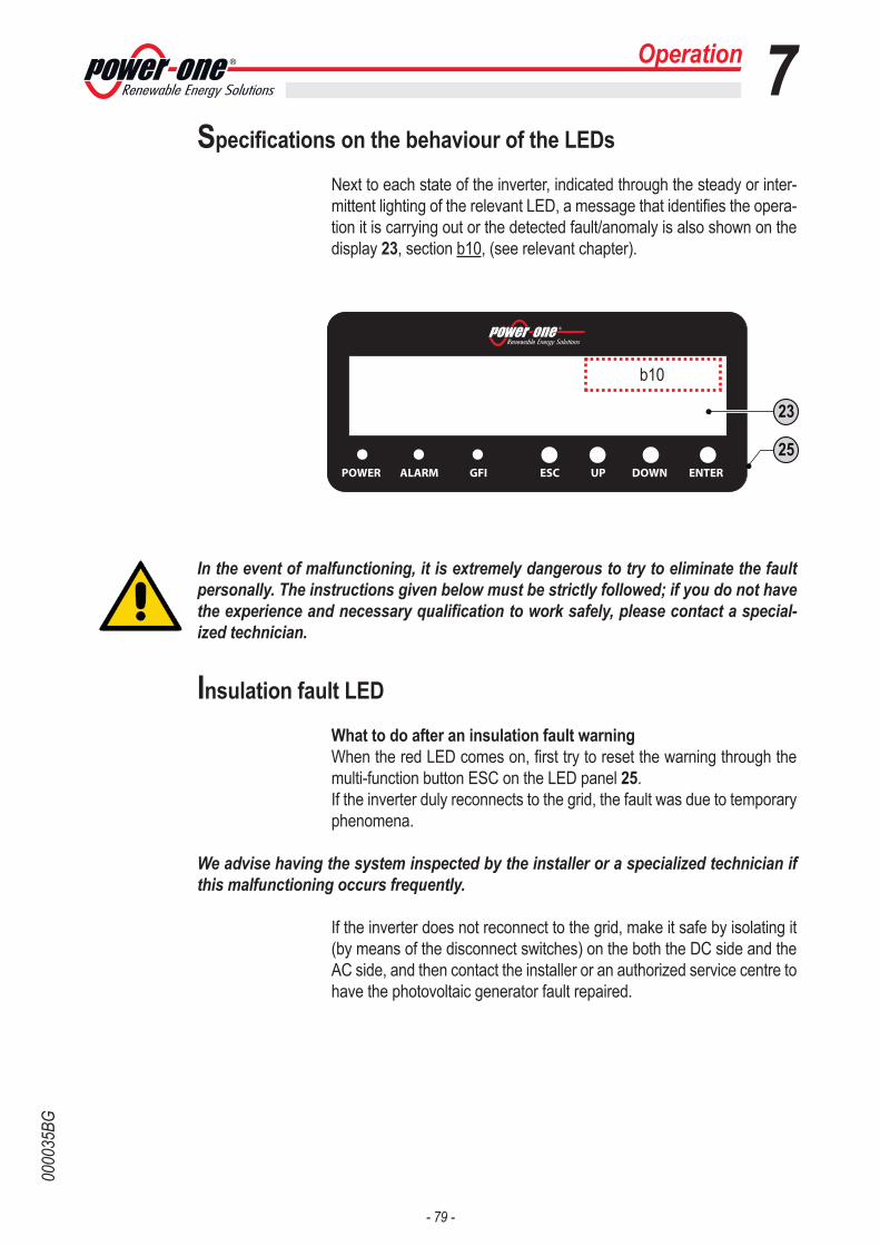
- 79 -
0000
35BG
Specifications on the behaviour of the LEDs
Next to each state of the inverter, indicated through the steady or inter-mittent lighting of the relevant LED, a message that identifies the opera-tion it is carrying out or the detected fault/anomaly is also shown on the display 23, section b10, (see relevant chapter).
In the event of malfunctioning, it is extremely dangerous to try to eliminate the fault personally. The instructions given below must be strictly followed; if you do not have the experience and necessary qualification to work safely, please contact a special-ized technician.
Insulation fault LED
What to do after an insulation fault warning When the red LED comes on, first try to reset the warning through the multi-function button ESC on the LED panel 25. If the inverter duly reconnects to the grid, the fault was due to temporary phenomena.
We advise having the system inspected by the installer or a specialized technician if this malfunctioning occurs frequently.
If the inverter does not reconnect to the grid, make it safe by isolating it (by means of the disconnect switches) on the both the DC side and the AC side, and then contact the installer or an authorized service centre to have the photovoltaic generator fault repaired.
Operation 7
POWER ALARM GFI ESC UP DOWN ENTER
23
25
b10

- 80 -
0000
35BG
Operation 7Description of the menus
The display 23 has a section b10 (graphic display) for moving through the menu using the buttons of the LED panel 25. Section b10 consists of 2 lines with 16 characters per line and can be used to:
• display the operating state of the inverter and the statistical data;• display the service messages for the operator;• display the alarm and fault messages for the operator;• changing the settings of the inverter.
Using the panel buttons
• The UP and DOWN buttons of the LED panel 25 are used to move around a menu or to increase/decrease the settable values.
• The ESC button allows access to the three main sub-menus, STATIS-TICS, SETTINGS and INFORMATION. This allows you to return to the previous sub-menu while moving through the menus.
• The ENTER button allows access to the required sub-menu while moving though the menus and allows the main menu scroll mode to be changed (icons b23 are activated):
CYCLIC: Cyclic display of the main parameters of the inverter. LOCKED: Display locked on the screen you want to monitor continu-
ously.
POWER ALARM GFI ESC UP DOWN ENTER
23
25
b10

- 81 -
0000
35BG
Statistics menu
Selecting STATISTICS from the three main sub-menus gives access to:
• TotalThis section of the menu allows you to display the Total statistics:Time: Total operating timeE-tot: Total energy producedVal. : Total production value, calculated with the currency and conver-sion coefficient set in the relevant section of the SETTINGS menuCO2: Amount of CO2 saved compared to fossil fuels
• PartialThis section of the menu allows you to display the partial statistics:Time: Partial operating timeE-par: Partial energy produced PPeak: Peak power value Val. : Partial production value, calculated with the currency and conver-sion coefficient set in the relevant section of the SETTINGS menuCO2: Partial amount of CO2 saved
* To reset all the counters of this sub-menu, press the ENTER button for more than 3 seconds. At the end of this time, you will hear a sound repeated 3 times.
• TodayThis section of the menu allows you to display the daily statistics:E-day: Daily energy producedPpeak: daily peak power valueVal. : Daily production value, calculated with the currency and conver-sion coefficient set in the relevant section of the SETTINGS menuCO2: Amount of CO2 saved daily
• Last 7 daysThis section of the menu allows you to display the statistics for the last 7 days:E-7d: Energy produced over the last 7 daysVal. : Value of production for the last 7 days, calculated with the currency and conversion coefficient set in the relevant section of the SETTINGS menu CO2: Amount of CO2 saved over the last 7 days
Operation 7

- 82 -
0000
35BG
Operation 7• Last monthThis section of the menu allows you to display the statistics for the last month:E-mon: Energy produced during the current monthVal. : Value of production for the last month, calculated with the currency and conversion coefficient set in the relevant section of the SETTINGS menu CO2: Amount of CO2 saved during the current month
• Last 30 daysThis section of the menu allows you to display the statistics for the last 30 days:E-30d: Energy produced over the last 30 daysVal. : Value of production for the last 30 days, calculated with the cur-rency and conversion coefficient set in the relevant section of the SET-TINGS menu CO2: Amount of CO2 saved over the last 30 days
• Last 365 daysThis section of the menu allows you to display the statistics for the last 365 days:E-365: Energy produced over the last 365 daysVal. : Value of production for the last 365 days, calculated with the cur-rency and conversion coefficient set in the relevant section of the SET-TINGS menuCO2: Amount of CO2 saved over the last 365 days
• User periodThis section of the menu allows the statistics for a period selected by the user to be displayed:Once the start and end dates for the period have been set, the following data are available:E: Energy produced during the selected periodVal. : Value of production for the selected period, calculated with the currency and conversion coefficient set in the relevant section of the SETTINGS menu CO2: Amount of CO2 saved during the selected period

- 83 -
0000
35BG
Operation 7Settings menu
When SETTINGS is selected from the three main sub-menus, the first screen for the password is displayed in the display.The default password is “0000”.This can be changed using the display buttons, always following the same procedure:• Use ENTER to scroll the digits (from left to right)• Use ESC to return to the previous digit (from right to left)• Press ESC several times to return to the previous menus• Use DOWN to progressively scroll the numerical scale downwards (from 9 to 0)• Use UP to progressively scroll the numerical scale upwards (from 0 to 9)After entering the password, press ENTER to access the information gathered in this section:
• AddressThis section of the menu allows you to set the address for the serial communication of single inverters connected to the RS485 line.The addresses that can be assigned are 2 to 63. Use the UP and DOWN buttons to scroll the numerical scale.At present, the ‘AUTO’ selection cannot be used
• Setting of DisplayThis section of the menu allows you to set the characteristics of the display:1. Light: setting of the mode and adjustment of the brightness of the display Mode:On: Light always onOff: Light always offAUTO: Automatic light control. The light comes on whenever a button is pressed and stays on for 30 sec, after which it gradually goes out.Intensity: adjustment of display brightness (scale from 1 to 9) 2. Contrast: adjustment of display contrast (scale from 1 to 9)3. Buzzer: button sound settingOn: the sound of the buttons is activatedOff: the sound of the buttons is deactivated
• ServiceThis section of the menu is reserved for installers. To access this, it is necessary to have a dedicated password that will be provided by the Power-One Service.

- 84 -
0000
35BG
Operation 7• New PWThis section of the menu allows you to change the password for access-ing the settings menu (default 0000).
We ADVISE you to be very careful in memorizing the new password. If the Password is misplaced, it will not be possible to access the inverter, since there is no Reset function for security reasons.
• CurrencyThis section of the menu allows you to set the name of the currency and the value given to 1 kWh of energy produced. The correct setting of these parameters allows you to display the actual earning/saving given by the system. Name: the chosen value is set (default is Euro)Val/KWh: indicates the cost/incentive of 1 KWh expressed in the chosen currency (default is 0.50).
• Date/TimeAllows you to set the current date and time (daylight saving time not included)
• LanguageAllows you to set the required menu language
• VstartThis section of the menu allows you to set the Vstart voltage (separately for both channels if they are configured in independent mode), to adapt it to the requirements of the system.
We advise changing the activation voltage only if really necessary and to set it to the correct value: the photovoltaic generator sizing instrument available on the Internet site of Power-One indicates whether it is necessary to change the Vstart and the value to set.
• AutotestAfter the Autotest procedure, the following information is available:- Nominal threshold (set in the inverter)- Value of the quantity found during autotest- Nominal operation time (set in the inverter)- Operation time foundThe values can be used to fill in the attached ENEL documents.If the test is not passed, the machine stops until the test is passed. The tests that can be carried out are the following:Max Voltage: Disconnection from the grid due to “Overvoltage” that can be carried out on the three phases R, S and T.Min Voltage: Disconnection from the grid due to “Undervoltage” that can be carried out on the three phases R, S and T.Max Frequency: Disconnection from the grid due to “Over Frequency” Min Frequency: Disconnection from the grid due to “Under Frequency”

- 85 -
0000
35BG
Operation 7• AlarmThis section of the menu allows you to set the switching of a relay con-tact (available as a normally open contact – N.O. – and also as a nor-mally closed contact – N.C.). This contact can be used, for example, to: activate a siren or a visual alarm, control the disconnect device of an external transformer, or control an external device. Maximum ratings of the alarm contact: 240Vac/1A and 30Vdc/0.8AThe switching of the relay can be set in 4 different modes: PRODUCTION: the relay switches when the inverter connects to the grid.ALARM: the relay switches when there is an alarm (code E).ALARM (conf.): the relay switches if there are alarms (code E) or warn-ings (code W) chosen by the user from a list (the list may also show choices that are not envisaged for the specific model). CREPUSCULAR: the relay switches only when it exceeds the input voltage set for connection to the grid.
• Remote ControlThis section of the menu allows you to enable/disable the connection/disconnection of the inverter to/from the grid through the relevant control signal (R ON/OFF).Disable: the connection/disconnection of the inverter to/from the grid is dictated by the input (voltage from the photovoltaic generator) and output (grid voltage) parameters of the inverter.Enable: the connection/disconnection of the inverter to/from the grid is dictated by the state of the R ON/OFF signal compared to the GND sig-nal as well as by the input (voltage from the photovoltaic generator) and output (grid voltage) parameters of the inverter.
• UV prot. TThis section of the menu allows you to set the time for which the inverter stays connected to the grid after the input voltage has dropped below the Under Voltage limit (set at 70% of Vstart). Power-One sets the time at 60 sec. The user can set it at from 1 to 3600 sec.Example: with the UV Prot.time set at 60 seconds, if the Vin drops below 70% of Vstart at 9:00, the inverter stays connected to the grid (taking power from it) until 9:01.
• MPPTThis section of the menu allows you to set the parameters of the maxi-mum power point search (MPPT) function. This function is useful when there are shadowed areas on the PV generator that can create several maximum power points in the work curve.MPPT amplitude: the amplitude of the interference introduced in DC is chosen through the setting of this parameter to establish the optimal working point. There are 3 settings to choose from (LOW, MEDIUM, HIGH). The default setting is MEDIUM.Multi-max scan: through the setting of this parameter, you can enable/disable the scan, decide the frequency with which the scan is carried out and override it manually.

- 86 -
0000
35BG
Operation 7Enable/Disable: Enables/Disables the scan for identifying the maxi-mum power point of the system. Scan Interval: this allows you to set the interval of time between scans. It must be borne in mind that, the shorter the interval between scans, the greater will be the loss of production due to the fact that, during the scan, energy is transferred to the grid but not at the maximum power point. Each scan takes 2 seconds. Manual Scan: Allows you to start (asynchronously to the periodicity set through the Scan Interval) the manual scanning of the photovoltaic gen-erator for peak point tracking. • Analogue InputsThis section of the menu allows you to set the analogue sensors con-nected at the input (AN1 and AN2)Setting of Gain: Allows you to set the gain of the sensorSetting of Offset: Allows you to set the offset of the sensorSetting of Unit of M.: Allows you to set the unit of measure of the sensor
For further details, specifications and connection diagrams of compatible Power-One sensors, consult the Installation chapter.
SENSORS PT100 AND PT1000(can be directly connected to the corresponding analogue input; the PT100/PT1000 inputs of the acquisition card do not require the configu-ration of gain and offset)• PVI-AEC-T100-ADH: adhesive PT100 sensor for module temperature measurement• PVI-AEC-T100-BOX: PT100 sensor for ambient temperature meas-urement in IP65 container.• PVI-AEC-T1000-BOX: PT1000 sensor for ambient temperature meas-urement in IP65 container.
• Alarm MsgThis section of the menu allows you to enter a customized message that is displayed on the display immediately after the specific error message has been displayed.Enable/Disable: Enables/Disables the display of customized messagesWriting of Msg: you can write your customized message that can be written on two lines of 16 characters each. To write the message, use the UP/DOWN arrows to choose the character you wish to enter and press ENTER to confirm.
- 87 -
0000
35BG
Operation 7Information menu
• Product IDAllows you to display the product identification code.
• Serial No.Allows you to display the serial number of the equipment.
• FirmwareAllows you to display the revision of the firmware installed in the equip-ment.
• Country selectorAllows you to display information regarding the grid standard set with the rotary selectors.- Current value: Displays the set grid standard.- New value: If the position of the rotary switches is changed (a new grid standard is therefore selected) during operation, the new stand-ard selected will be displayed but will be made effective only after the equipment has been switched off and then on again and only if the time remaining for carrying out this operation has not expired (24h of opera-tion).- Set new: Allows you to confirm/set the new grid standard set in the “New value” section of the previous menu. When this function is used, there will be no correspondence between the standard selected on the display and the position of the rotary selectors.- Time remaining: Displays the time remaining in which it is still pos-sible to set a new grid standard. When the time expires, “Locked” will be displayed, which indicates it is not possible to change the grid standard again.
• Fuse control (only for -S2X versions)• Strings: Displays the voltage and the state of the strings present at the input of the equipment. A string can be in one of the following states: OK, OFF (damaged) and ABS (absent)• Currents: Displays the current and the state of the strings present at the input of the equipment. A string current can be in one of the following states: OK, UNB (unbalanced current) and ABS (absent)
• Analogue InputsAllows you to display the reading of the measurements associated with the two analogue inputs A1/A2.

- 88 -
0000
36AG
Operation 7AUTOTEST procedureComplies with the guide for connections to the electricity grid of ENEL distribuzione
According to the “guide for connections to the electricity grid of ENEL distribuzione”, the autotest can be started through the display menu or using an RS485/USB converter through the dedicated interface soft-ware.The necessary conditions for being able to carry out the Autotest are as follows:• To have set the ENEL grid standard. • The inverter must be connected to the grid so as to be able to simulate the disconnection condition.• Do not carry out any operations during execution of the test.• Check that the device is permanently connected to the grid.
Execution of the autotest through the display menuGo to SETTINGS > Autotest > OV Test R OV Test S OV Test T UV Test R UV Test S UV Test T OF Test UF Test
In the section of the menu dedicated to the Autotest, the type of test the device is to start can be selected from the following:OV Test: Disconnection from the grid due to “Overvoltage”UV Test: Disconnection from the grid due to “Undervoltage”OF Test: Disconnection from the grid due to “Over Frequency”UF Test: Disconnection from the grid due to “Under Frequency”The OV and UV tests can be carried out on each single phase (R;S;T)
Description of the tests that can be carried out
OV TestDuring this test, the limit set for the maximum grid voltage (AC) is gradu-ally reduced until the threshold is reached where disconnection of the inverter from the grid occurs. A message indicating the start of the test is shown on the display.
At the end of the test, when the inverter has disconnected from the grid, the test result will be shown on the display.
Press the ESC button to go to the Autotest menu again to select the next test to be carried out.
Test in progress.....
Test V= ... VOK T= ... ms

- 89 -
0000
36AG
Operation 7UV TestDuring this test, the limit set for the minimum grid voltage (AC) is gradu-ally increased until the threshold is reached where disconnection of the inverter from the grid occurs. A message indicating the start of the test is shown on the display.
At the end of the test, when the inverter has disconnected from the grid, the test result will be shown on the display.
Press the ESC button to go to the Autotest menu again to select the next test to be carried out. OF TestDuring this test, the limit set for the maximum grid frequency (Hz) is gradually reduced until the threshold is reached where disconnection of the inverter from the grid occurs. A message indicating the start of the test is shown on the display.
At the end of the test, when the inverter has disconnected from the grid, the test result will be shown on the display.
Press the ESC button to go to the Autotest menu again to select the next test to be carried out.
UF Test During this test, the limit set for the minimum grid frequency (Hz) is grad-ually increased until the threshold is reached where disconnection of the inverter from the grid occurs. A message indicating the start of the test is shown on the display.
At the end of the test, when the inverter has disconnected from the grid, the test result will be shown on the display.
Press the ESC button to go to the Autotest menu again to select the next test to be carried out.
Once one of the tests (of the Autotest section) has been started, it takes place auto-matically. After the test has finished correctly, the inverter restores the factory-set switch-off values.
Test in progress.....
Test in progress.....
Test V= ... VOK T= ... ms
Test F= ... HzOK T= ... ms
Test in progress.....
Test F= ... HzOK T= ... ms

- 90 -
0000
37AG
8
General conditions Checking and maintenance operations must be carried out by special-ized staff assigned to carry out this work.
Maintenance operations must be carried out with the equipment disconnected from the grid, unless otherwise indicated.
For cleaning, DO NOT use rags made of filamentary material or corrosive products that may corrode parts of the equipment or generate electrostatic charges.Avoid temporary repairs. All repairs should be carried out using only genuine spare parts.The maintenance technician is under an obligation to promptly report any anomalies.
DO NOT allow the equipment to be used if problems of any kind are found, and restore the normal conditions correctly or in case make sure this is done.
Always use the personal protective equipment provided by the employer and comply with the safety conditions of the Accident prevention chapter.
Power-One accepts no liability if the checking and maintenance cycles indicated in this manual and in the attached documentation are not com-plied with correctly, and also when maintenance is entrusted to unquali-fied staff.
To maintain the correct working performance, have the systems checked by your installer after about 5 years of activity.
8 - Maintenance

- 91 -
0000
38BG
Maintenance 8Routine maintenance
Routine maintenance operations can be carried out directly by the user or by the installer.
Table: routine maintenance
200 h
Clean the equipment once a month; in particular, the lower grille on the wiring box 02 through which the air for cooling the heatsink 26 passes and the heatsink.If possible, use compressed air, an extractor or suitable pipe cleaners.
1,000 h
Clean the photovoltaic panels every six months, at the change of season or as necessary. The performance of the system depends very much on the condition of the PV panels.To clean, follow the specifications of the PV panel supplier.
1,000 h
Every six months or in the event of malfunctioning, check that the environmental conditions have not changed drastically (exposure to weather conditions); also check that the inverter or PV panels have not been shaded or isolated by foreign bodies.
2,000 h
Once a year or in the event of malfunctioning, check the tightness of the cable glands 10 or 11, the fixing of the connectors and the fixing of the front cover 08. Seepages may cause problems of damp and consequent short circuits.
Special maintenance
Special maintenance operations can be carried out only by the installer or qualified staff.
Table: special maintenance
1,000 h
Every six months or in the event of anomalies, especially after violent weather conditions, check the DC overvoltage surge arresters 15 (error W019) and the AC overvoltage surge arresters 18 (error W018).Both surge arresters are class II.Also check the fuses(error W017 only for S2X version) and replace the damaged ones. Before starting the inverter again, the cause of the fault must be resolved.
1,000 hEvery six months or in the event of malfunctioning, check the tightness of all the connections, especially the quick fit connectors, the cable glands 10 and 11, the terminal boards and the screws of the front cover 08.
1,000 h
Every six months or in the event of malfunctioning, check the inverter cooling fans.Before connecting to the grid, the inverter carries out a test on the internal fans and, in the event of an anomaly, generates an alarm signal.
2,000 hOnce a year or in the event of malfunctioning, check the backup battery and replace it if necessary. The battery normally lasts 10 years, but many conditions can reduce its efficiency. The battery is in the V housing of the communication card 09.

- 92 -
0000
38BG
Maintenance 8Alarm Messages
The equipment is able to indicate errors/warnings on the display only if the input voltage is higher than the Vdcmin voltage (POWER LED flash-ing or on; see operation chapter).The messages and their codes are indicated on the highlighted part b10 of the display 23.
POWER ALARM GFI ESC UP DOWN ENTER
23
25
b10
DisplayMessage
Display Codes
Alarm Cause Solution
Ground Fault
Red LED Ground Fault The alarm is generated when a ground leakage current is detected in the DC section of the system. The alarm is accompanied by the lighting up of the red LED on the front of the inverter.
If possible, measure the insulation resistance using a megohmmeter positioned between the photovoltaic field (positive terminal short-circuited to the negative pole) and ground.If the measured value is less than 1 megaohm, the photovoltaic generator must be checked by a technician/installer to identify and eliminate the problem.If the measured value is greater than 1 megaohm and the error warning continues to be present, contact the Power-one Service.
Degauss error
--- Degaussing state fail
Input OC E001 Input Overcurrent
The alarm appears when the inverter input current exceeds the set overcurrent threshold.
You must check whether the composition of the PV generator allows an input current that exceeds the maximum threshold allowed by the inverter and that the configuration of the (independent or parallel) inputs is carried out correctly. If the configuration of the PV generator and the setting of the input channels are suitable, contact thePower-one Service
Input OV E002 Input Overvoltage
This alarm is indicated when the inverter input voltage (coming from the PV generator) exceeds the operating threshold. The alarm is triggered before reaching the absolute threshold beyond which the inverter will be damaged. When the inverter input voltage exceeds the Over Voltage threshold, the inverter will not start because of the generation of the alarm.
Measure the input voltage in the inverter with a voltmeter.If it is higher than the maximum voltage of the operating interval, the alarm is real and you must check the configuration of the PV generator.If it is lower than the maximum voltage of the operating interval, the alarm is caused by an internal malfunctioning and you must contact the Power-one Service
No Parameters
E003 Internal Parameters Error
The main microcontroller is unable to correctly initialize the two DSPs (booster stage and inverter stage). This is usually due to communication problems on the internal bus of the inverter.
This is an error inside the inverter that cannot be checked externally. If the problem persists (after switching the inverter off and then on again), contact the Power-one Service.
Bulk OV E004 Bulk Overvoltage
Error inside the inverter. The alarm is raised when the voltage at the ends of the bulk capacitors exceeds the Over Voltage threshold.
The alarm can be caused by causes external to the inverter: an excessive inverter input voltage can be detected as a bulk overvoltage condition. In this case, it is advisable to check the inverter input voltage and, if this value is near the input OV threshold, re-examine the configuration of the photovoltaic generator. The alarm can be caused by causes internal to the inverter, and in this case, you must contact the Power-one Service.

- 93 -
0000
38BG
Maintenance 8Comm.Error E005 Internal
cation ErrorThe alarm occurs when there are communication problems between the control devices inside the inverter.
Error inside the inverter that cannot be checked externally. If the problem persists (after switching the inverter off and then on again), contact the Power-one Service.
Output OC E006 Output Overcurrent
The alarm appears when the inverter output current exceeds the output overcurrent threshold of the inverter.
Error inside the inverter that cannot be checked externally. If the problem persists (after switching the inverter off and then on again), contact the Power-one Service.
IGBT Sat E007 IGBT Saturation
The alarm appears when one of the active devices of the inverter is in saturation state.
Once the error appears, the inverter attempts to resume normal operation. If the error occurs sporadically, it may be caused by a sharp transition of the grid voltage or the input voltage but is not attributable to inverter malfunctioning. If the error is associated with an internal fault, it will continue to appear, and you must therefore contact the Power-one Service.
Internal error E009 Internal Error Error inside the inverter Error inside the inverter that cannot be checked externally. If the problem persists (after switching the inverter off and then on again), contact the Power-one Service.
Bulk Low E010 Low Bulk Voltage
The alarm can be caused by causes external to the inverter: a low inverter input voltage (just above the activation voltage) that is not accompanied by sufficient availability of power from the photovoltaic generator (typical condition of periods of insufficient irradiation).
If the error warning appears sporadically, it can be attributed to causes external to the inverter (insufficient irradiation, and therefore little power available from the PV generator) . If the problem appears systematically even in conditions of high solar radiation and with input voltage significantly higher than the activation voltage, contact the Power-one Service.
Ramp Fail E011 Bulk ramp timeout
Error inside the inverter regarding the time for starting steady state operation of the DC-DC circuit part (Booster).
Error inside the inverter that cannot be checked externally. If the problem persists (after switching the inverter off and then on again), contact the Power-one Service.
DcDc Fail E012 Booster module error revealed by Inverter
Error inside the inverter regarding the operation of the DC-DC circuit part (Booster).
Error inside the inverter that cannot be checked externally. If the problem persists (after switching the inverter off and then on again), contact the Power-one Service.
Wrong Mode E013 Wrong Input Mode (parallel instead of independent)
The alarm is generated only when the inverter is configured with parallel inputs. In this particular configuration, the inverter carries out the input voltage check of each of the two channels, and the alarm is raised if the two voltages differ by more than 20Vdc.
Make sure the setting of the "IN MODE" switch has been intentionally positioned on "PAR" and that the jumpers have been inserted between the two input channels.If the configuration of the inverter is correct, check that the input strings have the usual number of panels in series, of the usual make and with the same inclination/orientation. If both the configuration of the inverter and the characteristics of the PV generator comply with the specifications, contact the Power-one Service.
Over Temp. E014 Over-temperature
External temperature above 60°C. This parameter also depends on the power that the inverter must supply since the measurement of the temperatures is carried out internally and is affected by the heat dissipated by the components of the inverter.
Wait for the temperatures to which the inverter is exposed to return within operating range and for the inverter to cool down If the problem persists (once the ambient temperature has returned within the range), contact the Power-one Service. You must remember to wait for the time necessary to allow the inverter to cool down.
Bulk Cap Fail
E015 Bulk Capacitor Fail
Error inside the inverter regarding a problem in the bulk capacitors.
Error inside the inverter that cannot be checked externally. If the problem persists (after switching the inverter off and then on again), contact the Power-one Service.
Inverter Fail E016 Inverter module error revealed by Booster
The alarm is generated when a problem is detected in the inverter circuit part (DC/AC).
Error inside the inverter that cannot be checked externally. If the problem persists (after switching the inverter off and then on again), contact the Power-one Service.
Start Timeout
E017 Inverter module start-up timeout
Error inside the inverter regarding the time for starting steady state operation of the DC-AC circuit part (Inverter).
Error inside the inverter that cannot be checked externally. If the problem persists (after switching the inverter off and then on again), contact the Power-one Service.
Ground Fault
E018 Leakage current fail
The alarm is generated when, during normal operation of the inverter, a ground leakage current is detected in the DC section of the system. The alarm is accompanied by the lighting up of the red LED on the front of the inverter. The inverter may even also generate the E018 alarm message for AC leakage currents associated with the capacitive nature of the photovoltaic generator compared to ground.
If possible, measure the insulation resistance using a megohmmeter positioned between the photovoltaic field (positive terminal short-circuited to the negative pole) and ground.If the measured value is less than 1 megaohm, the PV generator must be checked by a technician/installer to identify and eliminate the problem.If the measured value is greater than 1 megaohm and the error warning continues to be present, contact the Power-one Service.
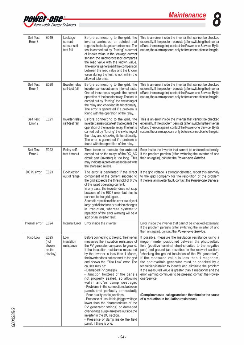
- 94 -
0000
38BG
Maintenance 8Self Test Error 3
E019 Leakage current sensor self-test fail
Before connecting to the grid, the inverter carries out an autotest that regards the leakage current sensor. The test is carried out by “forcing” a current of known value in the leakage current sensor: the microprocessor compares the read value with the known value. The error is generated if the comparison between the read value and the known value during the test is not within the allowed tolerance.
This is an error inside the inverter that cannot be checked externally. If the problem persists (after switching the inverter off and then on again), contact the Power-one Service. By its nature, the alarm appears only before connection to the grid.
Self Test Error 1
E020 Booster relay self-test fail
Before connecting to the grid, the inverter carries out some internal tests. One of these tests regards the correct operation of the booster relay. The test is carried out by “forcing” the switching of the relay and checking its functionality.The error is generated if a problem is found with the operation of the relay.
This is an error inside the inverter that cannot be checked externally. If the problem persists (after switching the inverter off and then on again), contact the Power-one Service. By its nature, the alarm appears only before connection to the grid.
Self Test Error 2
E021 Inverter relay self-test fail
Before connecting to the grid, the inverter carries out a test that regards the operation of the inverter relay. The test is carried out by “forcing” the switching of the relay and checking its functionality.The error is generated if a problem is found with the operation of the relay.
This is an error inside the inverter that cannot be checked externally. If the problem persists (after switching the inverter off and then on again), contact the Power-one Service. By its nature, the alarm appears only before connection to the grid.
Self Test Error 4
E022 Relay self-test timeout
Time taken to execute the autotest carried out on the relays of the DC_AC circuit part (inverter) is too long. This may indicate a problem associated with the aforesaid relays.
Error inside the inverter that cannot be checked externally. If the problem persists (after switching the inverter off and then on again), contact the Power-one Service.
DC inj error E023 Dc-Injection out of range
The error is generated if the direct component of the current supplied to the grid exceeds the threshold of 0.5% of the rated operating current. In any case, the inverter does not stop because of the E023 error, but tries to connect to the grid again. Sporadic repetition of the error is a sign of large grid distortions or sudden changes in irradiation, whereas systematic repetition of the error warning will be a sign of an inverter fault.
If the grid voltage is strongly distorted, report this anomaly to the grid company for the resolution of the problem If there is an inverter fault, contact the Power-one Service.
Internal error E024 Internal Error Error inside the inverter Error inside the inverter that cannot be checked externally. If the problem persists (after switching the inverter off and then on again), contact the Power-one Service.
Riso Low E025 (not shown on the display)
Low insulation resistance
Before connecting to the grid, the inverter measures the insulation resistance of the PV generator compared to ground. If the insulation resistance measured by the inverter is less than 1 Mohm, the inverter does not connect to the grid and shows the “Riso Low” error. The causes may be: - Damaged PV panel(s).- Junction box(es) of the panels not properly sealed, so allowing wa te r and /o r damp seepage ; - Problems in the connections between panels (not perfectly connected); - Poor quality cable junctions;- Presence of unsuitable (trigger voltage lower than the characteristics of the PV generator strings) or damaged overvoltage surge arresters outside the inverter in the DC section.- Presence of damp inside the field panel, if there is one.
If possible, measure the insulation resistance using a megohmmeter positioned between the photovoltaic field (positive terminal short-circuited to the negative pole) and ground (as described in the relevant section: "checking the ground insulation of the PV generator"). If the measured value is less than 1 megaohm, the photovoltaic generator must be checked by a technician/installer to identify and eliminate the problem If the measured value is greater than 1 megaohm and the error warning continues to be present, contact the Power-one Service.
(Damp increases leakage and can therefore be the cause of a reduction in insulation resistance).

- 95 -
0000
38BG
Maintenance 8Vref Error E026 Bad internal
reference voltage
Wrong measurement of the reference voltage inside the equipment
Internal error that cannot be checked externally. If the problem persists (even after switching the inverter off and then on again), contact the Power-one Service.
Error Meas V
E027 VGrid Measures Fault
Error in the internal measurement of the grid voltage (imposed by regulations) to have a measurement redundancy (2 measurements on the same parameter carried out by two different circuits).
This is an error inside the inverter that cannot be checked externally. If the problem is persistent (even after switching the inverter off and then on again), contact the Power-one Service.
Error Meas F
E028 FGrid Measures Fault
Error in the internal measurement of the grid frequency (imposed by regulations) to have a measurement redundancy (2 measurements on the same parameter carried out by two different circuits).
This is an error inside the inverter that cannot be checked externally. If the problem is persistent (even after switching the inverter off and then on again), contact the Power-one Service.
Error Meas Z
E029 ZGrid Measures Fault
Error in the internal measurement of the insulation resistance of the PV generator compared to ground (imposed by regulations) to have a measurement redundancy (2 measurements on the same parameter carried out by two different circuits).
Error inside the inverter that cannot be checked externally. The error occurs if the internal measurement is carried out before connection to the grid) If the problem is persistent (even after switching the inverter off and then on again), contact the Power-one Service.
Error Meas Ileak
E030 ILeak Measures Fault
Error in the internal measurement (carried out when the inverter is connected to the grid) of the leakage current of the DC side (PV generator) compared to ground (imposed by regulations) to have a measurement redundancy (2 measurements on the same parameter carried out by two different circuits).
This is an error inside the inverter that cannot be checked externally. If the problem is persistent (even after switching the inverter off and then on again), contact the Power-one Service.
Error Read V
E031 Wrong V Measure
Measurement of the internal voltage at the ends of the output relay out of range. There is too great a difference in voltage between the input and the output of the output relay.
This is an error inside the inverter that cannot be checked externally. If the problem appears repeatedly, you must contact the Power-one Service.
Error Read I E032 Wrong I Measure
Measurement of the output voltage unbalance (carried out between the three phases) out of range (only in three-phase models).
This is an error inside the inverter that cannot be checked externally. If the problem appears repeatedly, you must contact the Power-one Service.
UTH E033 Under Temperature
Temperature outside the inverter below -25°C
Wait for the temperatures to which the inverter is exposed to return wi th in operat ing range. If the problem persists, contact the Power-one Service. You must remember to wait for the time necessary to allow the inverter to warm up.
Interlock fail E034 IGBT not ready
Error inside the inverter Error inside the inverter that cannot be checked externally. If the problem persists (after switching the inverter off and then on again), contact the Power-one Service.
Remote Off E035 (not shown on the display)
Waiting remote ON
The inverter has been switched off remotely (remote OFF) and remains in waiting state for the signal that will switch it on again (remote ON).
Switch on the inverter remotely. If the unit does not switch on, disable the remote on/off function and switch the equipment off completely and then switch it on again. If the problem persists (after re-enabling the Remote ON/OFF function from the display), contact the Power-one Service.
Vout Avg error
E036 Average Vout out of range
The average grid voltage value (every 10 minutes) does not fall within the allowed ranges. The grid voltage at the point connected to the inverter is too high. This may be caused by a grid impedance that is too high. Towards the end of the timeout, the inverter limits the power to check whether the grid voltage stabilizes within the normal parameters. If this does not happen, the inverter disconnects from the grid.
Check the grid voltage at the inverter connection point. If the grid voltage diverges from the range because of grid conditions, ask the grid company to adjust the grid voltage. If the grid company authorizes a change to the inverter parameters, arrange the new limits with the Power-one Service.
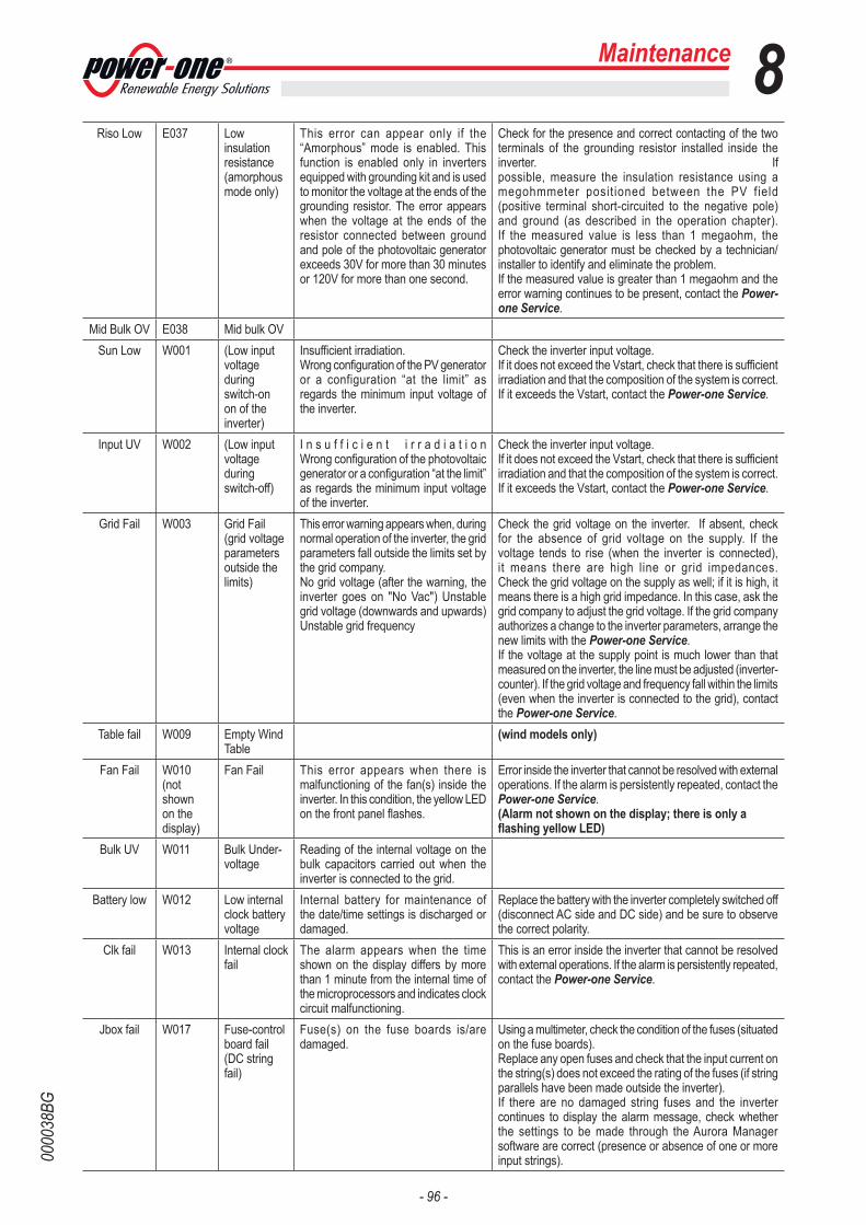
- 96 -
0000
38BG
Riso Low E037 Low insulation resistance (amorphous mode only)
This error can appear only if the “Amorphous” mode is enabled. This function is enabled only in inverters equipped with grounding kit and is used to monitor the voltage at the ends of the grounding resistor. The error appears when the voltage at the ends of the resistor connected between ground and pole of the photovoltaic generator exceeds 30V for more than 30 minutes or 120V for more than one second.
Check for the presence and correct contacting of the two terminals of the grounding resistor installed inside the inverter. If possible, measure the insulation resistance using a megohmmeter posit ioned between the PV field (positive terminal short-circuited to the negative pole) and ground (as described in the operation chapter). If the measured value is less than 1 megaohm, the photovoltaic generator must be checked by a technician/installer to identify and eliminate the problem. If the measured value is greater than 1 megaohm and the error warning continues to be present, contact the Power-one Service.
Mid Bulk OV E038 Mid bulk OVSun Low W001 (Low input
voltage during switch-on on of the inverter)
Insufficient irradiation.Wrong configuration of the PV generator or a configuration “at the limit” as regards the minimum input voltage of the inverter.
Check the inverter input voltage. If it does not exceed the Vstart, check that there is sufficient irradiation and that the composition of the system is correct. If it exceeds the Vstart, contact the Power-one Service.
Input UV W002 (Low input voltage during switch-off)
I n s u f f i c i e n t i r r a d i a t i o n Wrong configuration of the photovoltaic generator or a configuration “at the limit” as regards the minimum input voltage of the inverter.
Check the inverter input voltage. If it does not exceed the Vstart, check that there is sufficient irradiation and that the composition of the system is correct. If it exceeds the Vstart, contact the Power-one Service.
Grid Fail W003 Grid Fail (grid voltage parameters outside the limits)
This error warning appears when, during normal operation of the inverter, the grid parameters fall outside the limits set by the grid company.No grid voltage (after the warning, the inverter goes on "No Vac") Unstable grid voltage (downwards and upwards) Unstable grid frequency
Check the grid voltage on the inverter. If absent, check for the absence of grid voltage on the supply. If the voltage tends to rise (when the inverter is connected), it means there are high line or grid impedances. Check the grid voltage on the supply as well; if it is high, it means there is a high grid impedance. In this case, ask the grid company to adjust the grid voltage. If the grid company authorizes a change to the inverter parameters, arrange the new limits with the Power-one Service.If the voltage at the supply point is much lower than that measured on the inverter, the line must be adjusted (inverter-counter). If the grid voltage and frequency fall within the limits (even when the inverter is connected to the grid), contact the Power-one Service.
Table fail W009 Empty Wind Table
(wind models only)
Fan Fail W010 (not shown on the display)
Fan Fail This error appears when there is malfunctioning of the fan(s) inside the inverter. In this condition, the yellow LED on the front panel flashes.
Error inside the inverter that cannot be resolved with external operations. If the alarm is persistently repeated, contact the Power-one Service.(Alarm not shown on the display; there is only a flashing yellow LED)
Bulk UV W011 Bulk Under- voltage
Reading of the internal voltage on the bulk capacitors carried out when the inverter is connected to the grid.
Battery low W012 Low internal clock battery voltage
Internal battery for maintenance of the date/time settings is discharged or damaged.
Replace the battery with the inverter completely switched off (disconnect AC side and DC side) and be sure to observe the correct polarity.
Clk fail W013 Internal clock fail
The alarm appears when the time shown on the display differs by more than 1 minute from the internal time of the microprocessors and indicates clock circuit malfunctioning.
This is an error inside the inverter that cannot be resolved with external operations. If the alarm is persistently repeated, contact the Power-one Service.
Jbox fail W017 Fuse-control board fail (DC string fail)
Fuse(s) on the fuse boards is/are damaged.
Using a multimeter, check the condition of the fuses (situated on the fuse boards).Replace any open fuses and check that the input current on the string(s) does not exceed the rating of the fuses (if string parallels have been made outside the inverter).If there are no damaged string fuses and the inverter continues to display the alarm message, check whether the settings to be made through the Aurora Manager software are correct (presence or absence of one or more input strings).
Maintenance 8

- 97 -
0000
38BG
SPD DC protection
open
W018 SPD DC protection open
Overvoltage surge arresters situated on the DC side are damaged.
Look at the inspection window present on each surge arrester (DC side). If it is red, the surge arrester is damaged and the cartridge must be replaced. If the alarm status continues to be present even though all the surge arresters have a green inspection window, contact the Power-one Service.
SPD AC protection
open
W019 SPD AC protection open
Overvoltage surge arresters situated on the AC side are damaged.
Look at the inspection window present on each surge arrester (AC side). If it is red, the surge arrester is damaged and the cartridge must be replaced. If the alarm status continues to be present even though all the surge arresters have a green inspection window, contact the Power-one Service.
Maintenance 8

- 98 -
0000
40AG
Maintenance 8Verification of ground leakage
If the inverter has reported a ground fault, there may be a ground leaka-ge from the PV generator (DC side).
To check this, measure the voltage between the positive pole and ground and between the negative pole (of the PV generator) and ground using a voltmeter whose input accepts a voltage of at least 1000 Volts.
Behaviour of a system without leakage
Due to the capacitive effect of the PV generator, during the first mo-ments that the voltmeter is connected between one of the two poles and ground, it will measure a voltage of about Voc/2, which will tend to stabilize around 0V if there is no ground leakage, as shown in the graph below:
Voc
V
t
+Vs
-Vs
The internal resistance of the vol-tmeter tends to zero the voltage present on the PV generator due to the capacitive effect.
How to make the measurement:
Volt
(+)
(-)
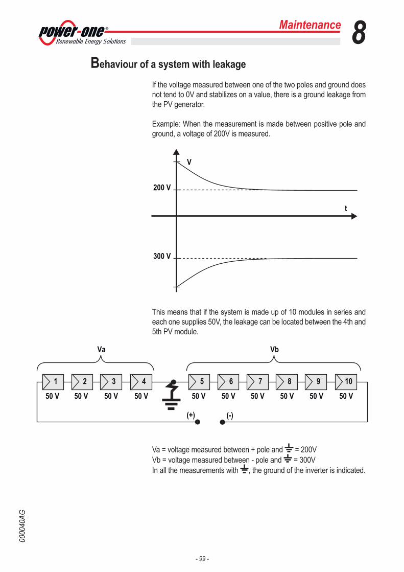
- 99 -
0000
40AG
Behaviour of a system with leakage
If the voltage measured between one of the two poles and ground does not tend to 0V and stabilizes on a value, there is a ground leakage from the PV generator.
Example: When the measurement is made between positive pole and ground, a voltage of 200V is measured.
This means that if the system is made up of 10 modules in series and each one supplies 50V, the leakage can be located between the 4th and 5th PV module.
Va = voltage measured between + pole and = 200VVb = voltage measured between - pole and = 300VIn all the measurements with , the ground of the inverter is indicated.
V
200 V
300 V
t
(+) (-)
50 V 50 V 50 V 50 V
Va
50 V 50 V
1 2 3 4 7 85 6 9 10
Vb
50 V 50 V 50 V 50 V
Maintenance 8
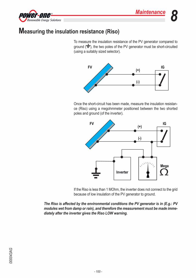
- 100 -
0000
43AG
Maintenance 8Measuring the insulation resistance (Riso)
To measure the insulation resistance of the PV generator compared to ground ( ), the two poles of the PV generator must be short-circuited (using a suitably sized selector).
Once the short-circuit has been made, measure the insulation resistan-ce (Riso) using a megohmmeter positioned between the two shorted poles and ground (of the inverter).
If the Riso is less than 1 MOhm, the inverter does not connect to the grid because of low insulation of the PV generator to ground.
The Riso is affected by the environmental conditions the PV generator is in (E.g.: PV modules wet from damp or rain), and therefore the measurement must be made imme-diately after the inverter gives the Riso LOW warning.
FV
MegaInverter
(+)
(-)
IG
FV(+)
(-)
IG
- 101 -
0000
39AG
Storage and dismantling
Storage of the equipment or prolonged stop
If the equipment is not used immediately or is stored for long periods, check that it is correctly packed and contact Power-One for storage instructions.The equipment must be stored in well-ventilated indoor areas that do not have characteristics that might damage the components of the equip-ment.
Restarting after a long or prolonged stop requires a check and, in some cases, the removal of oxidation and dust that will also have settled inside the equipment if not suitable protected.
Dismantling, decommissioning and disposal
Power-One CANNOT be held responsible for disposal of the equipment: displays, cables, batteries, accumulators, etc., and therefore the customer must dispose of these substances, which are potentially harmful to the environment, in accordance with the regulations in force in the country of installation.
If the equipment is dismantled, to dispose of the products it consists of, you must stick to the regulations in force in the country of destination and in any case avoid causing any kind of pollution.
Dispose of the various types of materials that the parts of the equipment consist of in dumps that are suitable for the purpose.
Table: disposal of components
Maintenance 8
COMPONENT MATERIAL OF CONSTRUCTIONFrame, brackets, supports ............................................................................................... Arc-welded steel FE37Casing or covers ................................................................................................................................ABS, plasticPaint ................................................................................................................................................. RAL .............Gaskets and seals ............................................................................................................ Rubber / Teflon / VitonElectrical cables .........................................................................................................................Copper / RubberCable trays ...........................................................................................................................Polyethylene / NylonBackup battery .................................................................................................................. Nickel / Lead/ Lithium