
TriCore C Compiler, Assembler, Linker User's Manual · Chapter 5: Using the Compiler Describes how...
249
MA060-024-00-00 Doc. ver .: 1.7 TriCore v2.5 C Compiler, Assembler, Linker User’s Manual
Transcript of TriCore C Compiler, Assembler, Linker User's Manual · Chapter 5: Using the Compiler Describes how...

MA060−024−00−00Doc. ver.: 1.7
TriCore v2.5
C Compiler,Assembler, LinkerUser’s Manual

A publication of
Altium BV
Documentation Department
Copyright 2002−2006 Altium BV
All rights reserved. Reproduction in whole or part is prohibitedwithout the written consent of the copyright owner.
TASKING is a brand name of Altium Limited.
The following trademarks are acknowledged:
FLEXlm is a registered trademark of Macrovision Corporation.Intel is a trademark of Intel Corporation.
Motorola is a registered trademark of Motorola, Inc.MS−DOS and Windows are registered trademarks of Microsoft Corporation.
SUN is a trademark of Sun Microsystems, Inc.UNIX is a registered trademark of X/Open Company, Ltd.
All other trademarks are property of their respective owners.
Data subject to alteration without notice.
http://www.tasking.comhttp://www.altium.com

The information in this document has been carefully reviewed and isbelieved to be accurate and reliable. However, Altium assumes no liabilitiesfor inaccuracies in this document. Furthermore, the delivery of thisinformation does not convey to the recipient any license to use or copy thesoftware or documentation, except as provided in an executed licenseagreement covering the software and documentation.
Altium reserves the right to change specifications embodied in thisdocument without prior notice.

TABLE OFCONTENTS
CONTENTS

Table of ContentsIVCO
NTEN
TS
CONTENTS

Table of Contents V
• • • • • • • •
SOFTWARE INSTALLATION AND CONFIGURATION 1−1
1.1 Introduction 1−3. . . . . . . . . . . . . . . . . . . . . . . . . . . . . . . . . . . .
1.2 Software Installation 1−3. . . . . . . . . . . . . . . . . . . . . . . . . . . . .
1.2.1 Installation for Windows 1−3. . . . . . . . . . . . . . . . . . . . . . . . . .
1.2.2 Installation for Linux 1−4. . . . . . . . . . . . . . . . . . . . . . . . . . . . .
1.2.3 Installation for UNIX Hosts 1−6. . . . . . . . . . . . . . . . . . . . . . .
1.3 Software Configuration 1−7. . . . . . . . . . . . . . . . . . . . . . . . . . .
1.3.1 Configuring the Embedded Development Environment 1−7
1.3.2 Configuring the Command Line Environment 1−9. . . . . . . .
1.4 Licensing TASKING Products 1−12. . . . . . . . . . . . . . . . . . . . . .
1.4.1 Obtaining License Information 1−12. . . . . . . . . . . . . . . . . . . .
1.4.2 Installing Node−Locked Licenses 1−13. . . . . . . . . . . . . . . . . . .
1.4.3 Installing Floating Licenses 1−14. . . . . . . . . . . . . . . . . . . . . . . .
1.4.4 Modifying the License File Location 1−16. . . . . . . . . . . . . . . .
1.4.5 How to Determine the Host ID 1−17. . . . . . . . . . . . . . . . . . . .
1.4.6 How to Determine the Host Name 1−17. . . . . . . . . . . . . . . . .
GETTING STARTED 2−1
2.1 Introduction 2−3. . . . . . . . . . . . . . . . . . . . . . . . . . . . . . . . . . . .
2.2 Working With Projects in EDE 2−7. . . . . . . . . . . . . . . . . . . . .
2.3 Start EDE 2−8. . . . . . . . . . . . . . . . . . . . . . . . . . . . . . . . . . . . . . .
2.4 Using the Sample Projects 2−9. . . . . . . . . . . . . . . . . . . . . . . .
2.5 Create a New Project Space with a Project 2−9. . . . . . . . . .
2.6 Set Options for the Tools in the Toolchain 2−14. . . . . . . . . .
2.7 Build your Application 2−16. . . . . . . . . . . . . . . . . . . . . . . . . . .
2.8 How to Build Your Application on the Command Line 2−17
2.9 Debug getstart.elf 2−18. . . . . . . . . . . . . . . . . . . . . . . . . . . . . . .
TRICORE C LANGUAGE 3−1
3.1 Introduction 3−3. . . . . . . . . . . . . . . . . . . . . . . . . . . . . . . . . . . .
3.2 Data Types 3−3. . . . . . . . . . . . . . . . . . . . . . . . . . . . . . . . . . . . .
3.2.1 Fundamental Data Types 3−3. . . . . . . . . . . . . . . . . . . . . . . . .
3.2.2 Fractional Data Types 3−5. . . . . . . . . . . . . . . . . . . . . . . . . . . .

Table of ContentsVICO
NTEN
TS3.2.3 Bit Data Type 3−7. . . . . . . . . . . . . . . . . . . . . . . . . . . . . . . . . . .
3.2.4 Packed Data Types 3−8. . . . . . . . . . . . . . . . . . . . . . . . . . . . . .
3.3 Memory Qualifiers 3−10. . . . . . . . . . . . . . . . . . . . . . . . . . . . . . .
3.3.1 Declare a Data Object in a Special Part of Memory 3−10. . .
3.3.2 Declare a Data Object at an Absolute Address: __at() and __atbit() 3−13. . . . . . . . . . . . . . . . . . . . . . . . . . . . . . . . . . . .
3.4 Data Type Qualifiers 3−15. . . . . . . . . . . . . . . . . . . . . . . . . . . . .
3.4.1 Circular Buffers: __circ 3−15. . . . . . . . . . . . . . . . . . . . . . . . . . .
3.4.2 Declare an SFR Bit field: __sfrbit16 and __sfrbit32 3−16. . . .
3.4.3 Saturation: __sat 3−18. . . . . . . . . . . . . . . . . . . . . . . . . . . . . . . . .
3.5 Intrinsic Functions 3−19. . . . . . . . . . . . . . . . . . . . . . . . . . . . . . .
3.6 Using Assembly in the C Source: __asm() 3−20. . . . . . . . . . .
3.7 Controlling the Compiler: Pragmas 3−26. . . . . . . . . . . . . . . . .
3.8 Predefined Macros 3−30. . . . . . . . . . . . . . . . . . . . . . . . . . . . . . .
3.9 Functions 3−31. . . . . . . . . . . . . . . . . . . . . . . . . . . . . . . . . . . . . .
3.9.1 Inlining Functions: inline 3−31. . . . . . . . . . . . . . . . . . . . . . . . .
3.9.2 Interrupt and Trap Functions 3−33. . . . . . . . . . . . . . . . . . . . . .
3.9.2.1 Defining an Interrupt Service Routine 3−34. . . . . . . . . . . . . .
3.9.2.2 Defining a Trap Service Routine 3−35. . . . . . . . . . . . . . . . . . .
3.9.2.3 Defining a Trap Service Routine Class 6: __syscallfunc() 3−37
3.9.2.4 Enabling Interrupt Requests: __enable_, __bisr_() 3−38. . . .
3.9.3 Function Calling Modes: __indirect 3−39. . . . . . . . . . . . . . . . .
3.9.4 Parameter Passing and the Stack Model: __stackparm 3−40.
3.10 Compiler Generated Sections 3−43. . . . . . . . . . . . . . . . . . . . . .
3.11 Switch Statement 3−47. . . . . . . . . . . . . . . . . . . . . . . . . . . . . . . .
3.12 Libraries 3−48. . . . . . . . . . . . . . . . . . . . . . . . . . . . . . . . . . . . . . .
3.12.1 Overview of Libraries 3−49. . . . . . . . . . . . . . . . . . . . . . . . . . . .
3.12.2 Printf and Scanf Formatting Routines 3−50. . . . . . . . . . . . . . .
3.12.3 Rebuilding Libraries 3−52. . . . . . . . . . . . . . . . . . . . . . . . . . . . . .
TRICORE ASSEMBLY LANGUAGE 4−1
4.1 Introduction 4−3. . . . . . . . . . . . . . . . . . . . . . . . . . . . . . . . . . . .
4.2 Assembly Syntax 4−3. . . . . . . . . . . . . . . . . . . . . . . . . . . . . . . .
4.3 Assembler Significant Characters 4−4. . . . . . . . . . . . . . . . . . .

Table of Contents VII
• • • • • • • •
4.4 Operands 4−5. . . . . . . . . . . . . . . . . . . . . . . . . . . . . . . . . . . . . .
4.4.1 Operands and Addressing Modes 4−5. . . . . . . . . . . . . . . . . .
4.4.2 PCP Addressing Modes 4−8. . . . . . . . . . . . . . . . . . . . . . . . . . .
4.5 Symbol Names 4−8. . . . . . . . . . . . . . . . . . . . . . . . . . . . . . . . . .
4.6 Assembly Expressions 4−9. . . . . . . . . . . . . . . . . . . . . . . . . . . .
4.6.1 Numeric Constants 4−10. . . . . . . . . . . . . . . . . . . . . . . . . . . . . .
4.6.2 Strings 4−11. . . . . . . . . . . . . . . . . . . . . . . . . . . . . . . . . . . . . . . . .
4.6.3 Expression Operators 4−12. . . . . . . . . . . . . . . . . . . . . . . . . . . .
4.7 Built−in Assembly Functions 4−14. . . . . . . . . . . . . . . . . . . . . .
4.8 Assembler Directives and Controls 4−18. . . . . . . . . . . . . . . . .
4.8.1 Overview of Assembler Directives 4−19. . . . . . . . . . . . . . . . .
4.8.2 Overview of Assembler Controls 4−21. . . . . . . . . . . . . . . . . . .
4.9 Working with Sections 4−22. . . . . . . . . . . . . . . . . . . . . . . . . . .
4.10 Macro Operations 4−24. . . . . . . . . . . . . . . . . . . . . . . . . . . . . . .
4.10.1 Defining a Macro 4−24. . . . . . . . . . . . . . . . . . . . . . . . . . . . . . . .
4.10.2 Calling a Macro 4−25. . . . . . . . . . . . . . . . . . . . . . . . . . . . . . . . .
4.10.3 Using Operators for Macro Arguments 4−27. . . . . . . . . . . . . .
4.10.4 Using the .DUP, .DUPA, .DUPC, .DUPF Directives as Macros 4−31. . . . . . . . . . . . . . . . . . . . . . . . . . . . . . . . . . . . . .
4.10.5 Conditional Assembly: .IF, .ELIF and .ELSE Directives 4−31.
USING THE COMPILER 5−1
5.1 Introduction 5−3. . . . . . . . . . . . . . . . . . . . . . . . . . . . . . . . . . . .
5.2 Compilation Process 5−4. . . . . . . . . . . . . . . . . . . . . . . . . . . . .
5.3 Compiler Optimizations 5−5. . . . . . . . . . . . . . . . . . . . . . . . . .
5.3.1 Optimize for Size or Speed 5−9. . . . . . . . . . . . . . . . . . . . . . .
5.4 Calling the Compiler 5−10. . . . . . . . . . . . . . . . . . . . . . . . . . . . .
5.5 How the Compiler Searches Include Files 5−16. . . . . . . . . . .
5.6 Compiling for Debugging 5−16. . . . . . . . . . . . . . . . . . . . . . . . .
5.7 C Code Checking: MISRA−C 5−17. . . . . . . . . . . . . . . . . . . . . . .
5.8 C Compiler Error Messages 5−19. . . . . . . . . . . . . . . . . . . . . . .

Table of ContentsVIIICO
NTEN
TSUSING THE ASSEMBLER 6−1
6.1 Introduction 6−3. . . . . . . . . . . . . . . . . . . . . . . . . . . . . . . . . . . .
6.2 Assembly Process 6−3. . . . . . . . . . . . . . . . . . . . . . . . . . . . . . .
6.3 Assembler Optimizations 6−4. . . . . . . . . . . . . . . . . . . . . . . . .
6.4 Calling the Assembler 6−5. . . . . . . . . . . . . . . . . . . . . . . . . . . .
6.5 Specifying a Target Processor 6−8. . . . . . . . . . . . . . . . . . . . .
6.6 How the Assembler Searches Include Files 6−9. . . . . . . . . .
6.7 Generating a List File 6−9. . . . . . . . . . . . . . . . . . . . . . . . . . . .
6.8 Assembler Error Messages 6−10. . . . . . . . . . . . . . . . . . . . . . . .
USING THE LINKER 7−1
7.1 Introduction 7−3. . . . . . . . . . . . . . . . . . . . . . . . . . . . . . . . . . . .
7.2 Linking Process 7−4. . . . . . . . . . . . . . . . . . . . . . . . . . . . . . . . .
7.2.1 Phase 1: Linking 7−6. . . . . . . . . . . . . . . . . . . . . . . . . . . . . . . .
7.2.2 Phase 2: Locating 7−7. . . . . . . . . . . . . . . . . . . . . . . . . . . . . . . .
7.2.3 Linker Optimizations 7−9. . . . . . . . . . . . . . . . . . . . . . . . . . . . .
7.3 Calling the Linker 7−10. . . . . . . . . . . . . . . . . . . . . . . . . . . . . . .
7.4 Linking with Libraries 7−14. . . . . . . . . . . . . . . . . . . . . . . . . . . .
7.4.1 Specifying Libraries to the Linker 7−15. . . . . . . . . . . . . . . . . .
7.4.2 How the Linker Searches Libraries 7−17. . . . . . . . . . . . . . . . .
7.4.3 How the Linker Extracts Objects from Libraries 7−17. . . . . .
7.5 Incremental Linking 7−18. . . . . . . . . . . . . . . . . . . . . . . . . . . . .
7.6 Linking the C Startup Code 7−19. . . . . . . . . . . . . . . . . . . . . . .
7.7 Controlling the Linker with a Script 7−20. . . . . . . . . . . . . . . .
7.7.1 Purpose of the Linker Script Language 7−20. . . . . . . . . . . . . .
7.7.2 EDE and LSL 7−21. . . . . . . . . . . . . . . . . . . . . . . . . . . . . . . . . . . .
7.7.3 Structure of a Linker Script File 7−22. . . . . . . . . . . . . . . . . . . .
7.7.4 The Architecture Definition: Self−Designed Cores 7−26. . . .
7.7.5 The Derivative Definition: Self−Designed Processors 7−29. .
7.7.6 The Memory Definition: Defining External Memory 7−31. . .
7.7.7 The Section Layout Definition: Locating Sections 7−33. . . . .
7.7.8 The Processor Definition: Using Multi−Processor Systems 7−37. . . . . . . . . . . . . . . . . . . . . . . . . . . . . . . . . . . . . . . .

Table of Contents IX
• • • • • • • •
7.8 Linker Labels 7−38. . . . . . . . . . . . . . . . . . . . . . . . . . . . . . . . . . .
7.9 Generating a Map File 7−41. . . . . . . . . . . . . . . . . . . . . . . . . . . .
7.10 Linker Error Messages 7−42. . . . . . . . . . . . . . . . . . . . . . . . . . . .
USING THE UTILITIES 8−1
8.1 Introduction 8−3. . . . . . . . . . . . . . . . . . . . . . . . . . . . . . . . . . . .
8.2 Control Program 8−4. . . . . . . . . . . . . . . . . . . . . . . . . . . . . . . .
8.2.1 Calling the Control Program 8−4. . . . . . . . . . . . . . . . . . . . . . .
8.3 Make Utility 8−9. . . . . . . . . . . . . . . . . . . . . . . . . . . . . . . . . . . .
8.3.1 Calling the Make Utility 8−11. . . . . . . . . . . . . . . . . . . . . . . . . .
8.3.2 Writing a Makefile 8−12. . . . . . . . . . . . . . . . . . . . . . . . . . . . . . .
8.4 Archiver 8−23. . . . . . . . . . . . . . . . . . . . . . . . . . . . . . . . . . . . . . .
8.4.1 Calling the Archiver 8−23. . . . . . . . . . . . . . . . . . . . . . . . . . . . . .
8.4.2 Examples 8−26. . . . . . . . . . . . . . . . . . . . . . . . . . . . . . . . . . . . . .
INDEX

Table of ContentsXCO
NTEN
TS

Manual Purpose and Structure XI
• • • • • • • •
MANUAL PURPOSE AND STRUCTURE
Windows Users
The documentation explains and describes how to use the TriCoretoolchain to program a TriCore DSP. The documentation is primarily aimedat Windows users. You can use the tools either with the graphicalEmbedded Development Environment (EDE) or from the command line ina command prompt window.
UNIX Users
For UNIX the toolchain works the same as it works for the Windowscommand line.
Directory paths are specified in the Windows way, with back slashes as in.\include. Simply replace the back slashes by forward slashes for usewith UNIX: ./include.
Some characters have a special meaning in a UNIX shell. In such cases youmust escape the special characters. For example, ’−?’ must be specified as’−\?’ in some shells. See your UNIX documentation for more information.
Structure
The toolchain documentation consists of a User’s Manual (this manual)which includes a Getting Started section and a separate Reference Manual.
First you need to install the software. This is described in Chapter 1,Software Installation and Configuration
After installation you are ready to follow the Getting Started in Chapter 2.
Next, move on with the other chapters which explain how to use thecompiler, assembler, linker and the various utilities.
Once you are familiar with these tools, you can use the Reference Manualto lookup specific options and details to make full use of the TriCoretoolchain.

TriCore User’s ManualXIIMAN
UAL ST
RUCT
URE
SHORT TABLE OF CONTENTS
Chapter 1: Software Installation and Configuration
Guides you through the installation of the software. Describes the mostimportant settings, paths and filenames that you must specify to get thepackage up and running.
Chapter 2: Getting Started
Overview of the toolchain and its individual elements. Describes therelation between the toolchain and specific features of the TriCore.Explains step−by−step how to write, compile, assemble and debug yourapplication. Teaches how you can use projects to organize your files.
Chapter 3: TriCore C Language
The TASKING TriCore C compiler is fully compatible with ISO−C. Thischapter describes the specific TriCore features of the C language, includinglanguage extensions that are not standard in ISO−C. For example, pragmasare a way to control the compiler from within the C source.
Chapter 4: TriCore Assembly Language
Describes the specific features of the TriCore assembly language as well as’directives’, which are pseudo instructions that are interpreted by theassembler.
Chapter 5: Using the Compiler
Describes how you can use the compiler. An extensive overview of alloptions is included in the Reference Manual.
Chapter 6: Using the Assembler
Describes how you can use the assembler. An extensive overview of alloptions is included in the Reference Manual.
Chapter 7: Using the Linker
Describes how you can use the linker. An extensive overview of alloptions is included in the Reference Manual.
Chapter 8: Using the Utilities
Describes several utilities and how you can use them to facilitate varioustasks. The following utilities are included: control program, make utilityand archiver.

Manual Purpose and Structure XIII
• • • • • • • •
CONVENTIONS USED IN THIS MANUAL
Notation for syntax
The following notation is used to describe the syntax of command lineinput:
bold Type this part of the syntax literally.
italics Substitute the italic word by an instance. For example:
filename
Type the name of a file in place of the word filename.
{ } Encloses a list from which you must choose an item.
[ ] Encloses items that are optional. For example
ctc [ −? ]
Both ctc and ctc −? are valid commands.
| Separates items in a list. Read it as OR.
... You can repeat the preceding item zero or more times.
,... You can repeat the preceding item zero or more times,separating each item with a comma.
Example
ctc [option]... filename
You can read this line as follows: enter the command ctc with or withoutan option, follow this by zero or more options and specify a filename. Thefollowing input lines are all valid:
ctc test.cctc −g test.cctc −g −E test.c
Not valid is:
ctc −g
According to the syntax description, you have to specify a filename.

TriCore User’s ManualXIVMAN
UAL ST
RUCT
URE
Icons
The following illustrations are used in this manual:
Note: notes give you extra information.
Warning: read the information carefully. It prevents you from makingserious mistakes or from loosing information.
This illustration indicates actions you can perform with the mouse. Such asEDE menu entries and dialogs.
Command line: type your input on the command line.
Reference: follow this reference to find related topics.
Manual Purpose and Structure XV
• • • • • • • •
RELATED PUBLICATIONS
C Standards• C A Reference Manual (fifth edition) by Samual P. Harbison and Guy L.
Steele Jr. [2002, Prentice Hall]
• The C Programming Language (second edition) by B. Kernighan and D.Ritchie [1988, Prentice Hall]
• ISO/IEC 9899:1999(E), Programming languages − C [ISO/IEC]More information on the standards can be found athttp://www.ansi.org
• DSP−C, An Extension to ISO/IEC 9899:1999(E), Programming languages − C [TASKING, TK0071−14]
MISRA−C• MISRA−C:2004, Guidelines for the Use of the C Language in Critical
Systems [MIRA Ltd, 2004]See also http://www.misra−c.com
• Guidelines for the Use of the C Language in Vehicle Based Software[MIRA Ltd, 1998]See also http://www.misra.org.uk
TASKING Tools• TriCore C Compiler, Assembler, Linker Reference Manual
[Altium, MB060−024−00−00]
• TriCore C++ Compiler User’s Manual[Altium, MA60−012−00−00]
• TriCore CrossView Pro Debugger User’s Manual[Altium, MA060−043−00−00]
TriCore• TriCore 1 Unified Processor Core v1.3 Architecture Manual, Doc v1.3.3
[2002−09, Infineon]
• TriCore2 Architecture Overview Handbook [2002, Infineon]
• TriCore Embedded Application Binary Interface [2000, Infineon]

TriCore User’s ManualXVIMAN
UAL ST
RUCT
URE

1
SOFTWAREINSTALLATION ANDCONFIGURATION
CHAPTER

TriCore User’s Manual1−2INSTAL
LATION
1
CHAPTER

Software Installation and Configuration 1−3
• • • • • • • •
1.1 INTRODUCTION
This chapter guides you through the procedures to install the software ona Windows system or on a Linux or UNIX host.
The software for Windows has two faces: a graphical interface (EmbeddedDevelopment Environment) and a command line interface. The Linux andUNIX software has only a command line interface.
After the installation, it is explained how to configure the software andhow to install the license information that is needed to actually use thesoftware.
1.2 SOFTWARE INSTALLATION
1.2.1 INSTALLATION FOR WINDOWS
1. Start Windows 95/98/XP/NT/2000, if you have not already done so.
2. Insert the CD−ROM into the CD−ROM drive.
If the TASKING Showroom dialog box appears, proceed with Step 5.
3. Click the Start button and select Run...
4. In the dialog box type d:\setup (substitute the correct drive letter foryour CD−ROM drive) and click on the OK button.
The TASKING Showroom dialog box appears.
5. Select a product and click on the Install button.
6. Follow the instructions that appear on your screen.
You can find your serial number on the invoice, delivery note, or pickingslip delivered with the product.
7. License the software product as explained in section 1.4, LicensingTASKING Products.
TriCore User’s Manual1−4INSTAL
LATION
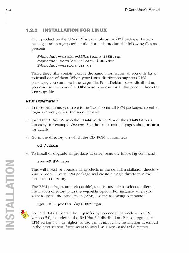
1.2.2 INSTALLATION FOR LINUX
Each product on the CD−ROM is available as an RPM package, Debianpackage and as a gzipped tar file. For each product the following files arepresent:
SWproduct−version−RPMrelease.i386.rpmswproduct_version−release_i386.debSWproduct−version.tar.gz
These three files contain exactly the same information, so you only haveto install one of them. When your Linux distribution supports RPMpackages, you can install the .rpm file. For a Debian based distribution,you can use the .deb file. Otherwise, you can install the product from the.tar.gz file.
RPM Installation
1. In most situations you have to be "root" to install RPM packages, so eitherlogin as "root", or use the su command.
2. Insert the CD−ROM into the CD−ROM drive. Mount the CD−ROM on adirectory, for example /cdrom. See the Linux manual pages about mountfor details.
3. Go to the directory on which the CD−ROM is mounted:
cd /cdrom
4. To install or upgrade all products at once, issue the following command:
rpm −U SW*.rpm
This will install or upgrade all products in the default installation directory/usr/local. Every RPM package will create a single directory in theinstallation directory.
The RPM packages are ’relocatable’, so it is possible to select a differentinstallation directory with the −−prefix option. For instance when youwant to install the products in /opt, use the following command:
rpm −U −−prefix /opt SW*.rpm
For Red Hat 6.0 users: The −−prefix option does not work with RPMversion 3.0, included in the Red Hat 6.0 distribution. Please upgrade toRPM verion 3.0.3 or higher, or use the .tar.gz file installation describedin the next section if you want to install in a non−standard directory.

Software Installation and Configuration 1−5
• • • • • • • •
Debian Installation
1. Login as a user.
Be sure you have read, write and execute permissions in the installationdirectory. Otherwise, login as "root" or use the su command.
2. Insert the CD−ROM into the CD−ROM drive. Mount the CD−ROM on adirectory, for example /cdrom. See the Linux manual pages about mountfor details.
3. Go to the directory on which the CD−ROM is mounted:
cd /cdrom
4. To install or upgrade all products at once, issue the following command:
dpkg −i sw*.deb
This will install or upgrade all products in a subdirectory of the defaultinstallation directory /usr/local.
Tar.gz Installation
1. Login as a user.
Be sure you have read, write and execute permissions in the installationdirectory. Otherwise, login as "root" or use the su command.
2. Insert the CD−ROM into the CD−ROM drive. Mount the CD−ROM on adirectory, for example /cdrom. See the Linux manual pages about mountfor details.
3. Go to the directory on which the CD−ROM is mounted:
cd /cdrom
4. To install the products from the .tar.gz files in the directory/usr/local, issue the following command for each product:
tar xzf SWproduct−version.tar.gz −C /usr/local
Every .tar.gz file creates a single directory in the directory where it isextracted.

TriCore User’s Manual1−6INSTAL
LATION
1.2.3 INSTALLATION FOR UNIX HOSTS
1. Login as a user.
Be sure you have read, write and execute permissions in the installationdirectory. Otherwise, login as "root" or use the su command.
If you are a first time user, decide where you want to install the product.By default it will be installed in /usr/local.
2. Insert the CD−ROM into the CD−ROM drive and mount the CD−ROM on adirectory, for example /cdrom.
Be sure to use an ISO 9660 file system with Rock Ridge extensionsenabled. See the UNIX manual pages about mount for details.
3. Go to the directory on which the CD−ROM is mounted:
cd /cdrom
4. Run the installation script:
sh install
Follow the instructions appearing on your screen.
First a question appears about where to install the software. The defaultanswer is /usr/local.
On some hosts the installation script asks if you want to install SW000098,the Flexible License Manager (FLEXlm). If you do not already have FLEXlmon your system, you must install it otherwise the product will not work onthose hosts. See section 1.4, Licensing TASKING Products.
If the script detects that the software has been installed before, thefollowing messages appear on the screen:
*** WARNING ***SWxxxxxx xxxx.xxxx already installed.Do you want to REINSTALL? [y,n]
Answering n (no) to this question causes installation to abort and thefollowing message being displayed:
=> Installation stopped on user request <=

Software Installation and Configuration 1−7
• • • • • • • •
Answer y (yes) to continue with the installation. The last message will be:
Installation of SWxxxxxx xxxx.xxxx completed.
5. If you purchased a protected TASKING product, license the softwareproduct as explained in section 1.4, Licensing TASKING Products.
1.3 SOFTWARE CONFIGURATION
Now you have installed the software, you can configure both theEmbedded Development Environment and the command line environmentfor Windows, Linux and UNIX.
1.3.1 CONFIGURING THE EMBEDDED DEVELOPMENTENVIRONMENT
After installation on Windows, the Embedded Development Environmentis automatically configured with default search paths to find theexecutables, include files and libraries. In most cases you can use thesesettings. To change the default settings, follow the next steps:
1. Double−click on the EDE icon on your desktop to start the EmbeddedDevelopment Environment (EDE).
2. From the Project menu, select Directories...
The Directories dialog box appears.
3. Fill in the following fields:
• In the Executable Files Path field, type the pathname of thedirectory where the executables are located. The default directory is$(PRODDIR)\bin.
• In the Include Files Path field, add the pathnames of thedirectories where the compiler and assembler should look forinclude files. The default directory is $(PRODDIR)\include.Separate pathnames with a semicolon (;).
The first path in the list is the first path where the compiler andassembler look for include files. To change the search order, simplychange the order of pathnames.

TriCore User’s Manual1−8INSTAL
LATION
• In the Library Files Path field, add the pathnames of thedirectories where the linker should look for library files. The defaultdirectory is $(PRODDIR)\lib. Separate pathnames with asemicolon (;).
The first path in the list is the first path where the linker looks forlibrary files. To change the search order, simply change the order ofpathnames.
Instead of typing the pathnames, you can click on the Configure...button.
A dialog box appears in which you can select and add directories, removethem again and change their order.

Software Installation and Configuration 1−9
• • • • • • • •
1.3.2 CONFIGURING THE COMMAND LINEENVIRONMENT
To facilitate the invocation of the tools from the command line (eitherusing a Windows command prompt or using Linux or UNIX), you can setenvironment variables.
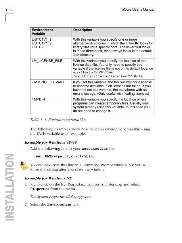
You can set the following variables:
EnvironmentVariable
Description
PATH With this variable you specify the directory in whichthe executables reside (for example: c:\ctc\bin).This allows you to call the executables when youare not in the bin directory.
Usually your system already uses the PATH variablefor other purposes. To keep these settings, youneed to add (rather than replace) the path. Use asemicolon (;) to separate pathnames.
CTCINC With this variable you specify one or more additionaldirectories in which the C compiler ctc looks forinclude files. The compiler first looks in thesedirectories, then always looks in the defaultinclude directory relative to the installationdirectory.
ASTCINC With this variable you specify one or more additionaldirectories in which the assembler astc looks forinclude files. The assembler first looks in thesedirectories, then always looks in the defaultinclude directory relative to the installationdirectory.
ASPCPINC With this variable you specify one or more additionaldirectories in which the assembler aspcp looks forinclude files. The assembler first looks in thesedirectories, then always looks in the defaultinclude directory relative to the installationdirectory.
CCTCBIN With this variable you specify the directory in whichthe control program cctc looks for the executabletools. The path you specify here should match thepath that you specified for the PATH variable.
CCTCOPT With this variable you specify options and/orarguments to each invocation of the control programcctc. The control program processes thesearguments before the command line arguments.
TriCore User’s Manual1−10INSTAL
LATION
DescriptionEnvironmentVariable
LIBTC1V1_2LIBTC1V1_3LIBTC2
With this variable you specify one or morealternative directories in which the linker ltc looks forlibrary files for a specific core. The linker first looksin these directories, then always looks in the defaultlib directory.
LM_LICENSE_FILE With this variable you specify the location of thelicense data file. You only need to specify thisvariable if the license file is not on its default location(c:\flexlm for Windows,/usr/local/flexlm/licenses for UNIX).
TASKING_LIC_WAIT If you set this variable, the tool will wait for a licenseto become available, if all licenses are taken. If youhave not set this variable, the tool aborts with anerror message. (Only useful with floating licenses)
TMPDIR With this variable you specify the location whereprograms can create temporary files. Usually yoursystem already uses this variable. In this case youdo not need to change it.
Table 1−1: Environment variables
The following examples show how to set an environment variable usingthe PATH variable as an example.
Example for Windows 95/98
Add the following line to your autoexec.bat file:
set PATH=%path%;c:\ctc\bin
You can also type this line in a Command Prompt window but you willloose this setting after you close the window.
Example for Windows NT
1. Right−click on the My Computer icon on your desktop and selectProperties from the menu.
The System Properties dialog appears.
2. Select the Environment tab.

Software Installation and Configuration 1−11
• • • • • • • •
3. In the list of System Variables select Path.
4. In the Value field, add the path where the executables are located to theexisting path information. Separate pathnames with a semicolon (;). Forexample: c:\ctc\bin.
5. Click on the Set button, then click OK.
Example for Windows XP / 2000
1. Right−click on the My Computer icon on your desktop and selectProperties from the menu.
The System Properties dialog appears.
2. Select the Advanced tab.
3. Click on the Environment Variables button.
The Environment Variables dialog appears.
4. In the list of System variables select Path.
5. Click on the Edit button.
The Edit System Variable dialog appears.
6. In the Variable value field, add the path where the executables arelocated to the existing path information. Separate pathnames with asemicolon (;). For example: c:\ctc\bin.
7. Click on the OK button to accept the changes and close the dialogs.
Example for UNIX
Enter the following line (C−shell):
setenv PATH $PATH:/usr/local/ctc/bin

TriCore User’s Manual1−12INSTAL
LATION
1.4 LICENSING TASKING PRODUCTS
TASKING products are protected with license management software(FLEXlm). To use a TASKING product, you must install the license keyprovided by TASKING for the type of license purchased.
You can run TASKING products with a node−locked license or with afloating license. When you order a TASKING product determine whichtype of license you need (UNIX products only have a floating license).
Node−locked license (PC only)
This license type locks the software to one specific PC so you can use theproduct on that particular PC only.
Floating license
This license type manages the use of TASKING product licenses amongusers at one site. This license type does not lock the software to onespecific PC or workstation but it requires a network. The software can thenbe used on any computer in the network. The license specifies thenumber of users who can use the software simultaneously. A systemallocating floating licenses is called a license server. A license managerrunning on the license server keeps track of the number of users.
1.4.1 OBTAINING LICENSE INFORMATION
Before you can install a software license you must have a "License Key"containing the license information for your software product. If you havenot received such a license key follow the steps below to obtain one.Otherwise, you can install the license.
Windows
1. Run the License Administrator during installation and follow the steps toRequest a license key from Altium by E−mail.
2. E−mail the license request to your local TASKING sales representative. Thelicense key will be sent to you by E−mail.

Software Installation and Configuration 1−13
• • • • • • • •
UNIX
1. If you need a floating license on UNIX, you must determine the host IDand host name of the computer where you want to use the licensemanager. Also decide how many users will be using the product. Seesection 1.4.5, How to Determine the Host ID and section 1.4.6, How toDetermine the Host Name.
2. When you order a TASKING product, provide the host ID, host name andnumber of users to your local TASKING sales representative. The licensekey will be sent to you by E−mail.
1.4.2 INSTALLING NODE−LOCKED LICENSES
If you do not have received your license key, read section 1.4.1, ObtainingLicense Information, before continuing.
1. Install the TASKING software product following the installation proceduredescribed in section 1.2.1, Installation for Windows, if you have not donethis already.
2. Create a license file by importing a license key or create one manually:
Import a license key
During installation you will be asked to run the License Administrator.Otherwise, start the License Administrator (licadmin.exe) manually.
In the License Administrator follow the steps to Import a license keyreceived from Altium by E−mail. The License Administrator creates alicense file for you.
Create a license file manually
If you prefer to create a license file manually, create a file called"license.dat" in the c:\flexlm directory, using an ASCII editor andinsert the license key information received by E−mail in this file. This file iscalled the "license file". If the directory c:\flexlm does not exist, createthe directory.
If you wish to install the license file in a different directory, see section1.4.4, Modifying the License File Location.

TriCore User’s Manual1−14INSTAL
LATION
If you already have a license file, add the license key information to theexisting license file. If the license file already contains any SERVER lines,you must use another license file. See section 1.4.4, Modifying the LicenseFile Location, for additional information.
The software product and license file are now properly installed.
1.4.3 INSTALLING FLOATING LICENSES
If you do not have received your license key, read section 1.4.1, ObtainingLicense Information, before continuing.
1. Install the TASKING software product following the installation proceduredescribed earlier in this chapter on each computer or workstation whereyou will use the software product.
2. On each PC or workstation where you will use the TASKING softwareproduct the location of a license file must be known, containing theinformation of all licenses. Either create a local license file or point to alicense file on a server:
Add a licence key to a local license file
A local license file can reduce network traffic.
On Windows, you can follow the same steps to import a license key orcreate a license file manually, as explained in the previous section with theinstallation of a node−locked license.
On UNIX, you have to insert the license key manually in the license file.The default location of the license file license.dat is in directory/usr/local/flexlm/licenses for UNIX.
If you wish to install the license file in a different directory, see section1.4.4, Modifying the License File Location.
If you already have a license file, add the license key information to theexisting license file. If the license file already contains any SERVER lines,make sure that the number of SERVER lines and their contents match,otherwise you must use another license file. See section 1.4.4, Modifyingthe License File Location, for additional information.

Software Installation and Configuration 1−15
• • • • • • • •
Point to a license file on the server
Set the environment variable LM_LICENSE_FILE to "port@host", wherehost and port come from the SERVER line in the license file. On Windows,you can use the License Administrator to do this for you. In the LicenseAdministrator follow the steps to Point to a FLEXlm License Server toget your licenses.
3. If you already have installed FLEXlm v8.4 or higher (for example as part ofanother product) you can skip this step and continue with step 4.Otherwise, install SW000098, the Flexible License Manager (FLEXlm), onthe license server where you want to use the license manager.
It is not recommended to run a license manager on a Windows 95 orWindows 98 machine. Use Windows XP, NT or 2000 instead, or use UNIXor Linux.
4. If FLEXlm has already been installed as part of a non−TASKING productyou have to make sure that the bin directory of the FLEXlm productcontains a copy of the Tasking daemon. This file part of the TASKINGproduct installation and is present in the flexlm subdirectory of thetoolchain. This file is also on every product CD that includes FLEXlm, indirectory licensing.
5. On the license server also add the license key to the license file. Followthe same instructions as with "Add a license key to a local license file" instep 2.
See the FLEXlm PDF manual delivered with SW000098, which is presenton each TASKING product CD, for more information.

TriCore User’s Manual1−16INSTAL
LATION
1.4.4 MODIFYING THE LICENSE FILE LOCATION
The default location for the license file on Windows is:
c:\flexlm\license.dat
On UNIX this is:
/usr/local/flexlm/licenses/license.dat
If you want to use another name or directory for the license file, each usermust define the environment variable LM_LICENSE_FILE.
If you have more than one product using the FLEXlm license manager youcan specify multiple license files to the LM_LICENSE_FILE environmentvariable by separating each pathname (lfpath) with a ’;’ (on UNIX ’:’):
Example Windows:
set LM_LICENSE_FILE=c:\flexlm\license.dat;c:\license.txt
Example UNIX:
setenv LM_LICENSE_FILE/usr/local/flexlm/licenses/license.dat:/myprod/license.txt
If the license file is not available on these hosts, you must setLM_LICENSE_FILE to port@host; where host is the host name of thesystem which runs the FLEXlm license manager and port is the TCP/IP portnumber on which the license manager listens.
To obtain the port number, look in the license file at host for a line startingwith "SERVER". The fourth field on this line specifies the TCP/IP portnumber on which the license server listens. For example:
setenv LM_LICENSE_FILE 7594@elliot
See the FLEXlm PDF manual delivered with SW000098, which is presenton each TASKING product CD, for detailed information.

Software Installation and Configuration 1−17
• • • • • • • •
1.4.5 HOW TO DETERMINE THE HOST ID
The host ID depends on the platform of the machine. Please use one ofthe methods listed below to determine the host ID.
Platform Tool to retrieve host ID Example host ID
HP−UX lanscan(use the station address withoutthe leading ’0x’)
0000F0050185
Linux hostid 11ac5702
SunOS/Solaris hostid 170a3472
Windows licadmin (License Administrator,or use lmhostid)
0060084dfbe9
Table 1−2: Determine the host ID
On Windows, the License Administrator (licadmin) helps you in theprocess of obtaining your license key.
If you do not have the program licadmin you can download it from ourWeb site at: http://www.tasking.com/support/flexlm/licadmin.zip . It isalso on every product CD that includes FLEXlm, in directory licensing.
1.4.6 HOW TO DETERMINE THE HOST NAME
To retrieve the host name of a machine, use one of the following methods.
Platform Method
UNIX hostname
Windows NT licadmin or:
Go to the Control Panel, open "Network". In the"Identification" tab look for "Computer Name".
Windows XP/2000 licadmin or:
Go to the Control Panel, open "System". In the "ComputerName" tab look for "Full computer name".
Table 1−3: Determine the host name

TriCore User’s Manual1−18INSTAL
LATION

2
GETTING STARTEDCHAPTER

TriCore User’s Manual2−2GET
TING
STA
RTED 2
CHAPTER

Getting Started 2−3
• • • • • • • •
2.1 INTRODUCTION
With the TASKING TriCore suite you can write, compile, assemble, linkand locate applications for the several TriCore cores. The TASKINGTriCore suite conforms to Infineon’s TriCore Embedded ApplicationsBinary Interface (EABI), which defines a set of standards to ensureinteroperability between software components.
Embedded Development Environment
The TASKING Embedded Development Environment (EDE) is a Windowsapplication that facilitates working with the tools in the toolchain and alsooffers project management and an integrated editor.
EDE has three main functions: Edit / Project management, Build andDebug. The figure below shows how these main functionalities relate toeach other.
makefile
makecompiler
absolute file
debugger
assemblerlinker
EDE
project managementeditor
tool options
toolchain selection
EDIT
BUILD
DEBUG
Figure 2−1: EDE development flow

TriCore User’s Manual2−4GET
TING
STA
RTED
In the Edit part you make all your changes:
− create a project space
− create and maintain one or more projects in a project space
− add, create and edit source files in a project
− set the options for each tool in the toolchain
− select another toolchain if you want to create an application foranother target than the TriCore.
In the Build part you build your files:
− a makefile (created by the Edit part) is used to invoke the neededtoolchain components, resulting in an absolute object file.
In the Debug part you can debug your project:
− call the TASKING debugger �CrossView Pro" with the generatedabsolute object file.
This Getting Started Chapter guides you step−by−step through the mostimportant features of EDE
The TASKING EDE is an embedded environment and differs from a nativeprogram development.
A native program development environment is often used to developapplications for systems where the host system and the target are thesame. Therefore, it is possible to run a compiled application directly fromthe development environment.
In an embedded environment, however, a simulator or target hardware isrequired to run an application. TASKING offers a number of simulatorsand target hardware debuggers.
Toolchain overview
You can use all tools in the toolchain from the embedded developmentenvironment (EDE) and from the command line in a Command Promptwindow or a UNIX shell.
The next illustration shows all components of the TriCore toolchain withtheir input and output files.

Getting Started 2−5
• • • • • • • •
assembly file
assembler
relocatable object file
CrossView Pro
C++ compiler
C++ source file.cc
debugger
C source file
C compiler
TriCore executionenvironment
.ic
cptc
ctc
astc
relocatable object library.a
archiverartc
xfwtc
list file .lst
.src
.o
C source file
assembly file
(hand coded).c
.asm(hand coded)
error messages .ers
linker
relocatable linker object file
ltc
.out
linker map file .map
error messages .elk
linker script file.lsl
relocatable linker object file .out
error messages .err
memory definition.mdffile
Motorola S−recordabsolute object file
.sre
Intel Hexabsolute object file
.hex
ELF/DWARF 2absolute object file
.elf
IEEE−695absolute object file
.abs
Figure 2−2: TriCore toolchain

TriCore User’s Manual2−6GET
TING
STA
RTED
The following table lists the file types used by the TriCore toolchain.
Extension Description
Source files
.cc C++ source file, input for the C++ compiler
.c C source file, input for the C compiler
.asm Assembler source file, hand coded
.lsl Linker script file using the Linker Script Language
Generated source files
.ic C source file, generated by the C++ compiler, input for the Ccompiler
.src Assembler source file, generated by the C compiler, does notcontain macros
Object files
.o ELF/DWARF relocatable object file, generated by the assembler
.a Archive with ELF/DWARF object files
.abs IEEE−695 absolute object file, generated by the locating part ofthe linker
.out Relocatable linker output file
.elf ELF/DWARF absolute object file, generated by the locating partof the linker
.hex Absolute Intel Hex object file
.sre Absolute Motorola S−record object file
List files
.lst Assembler list file
.map Linker map file
.mdf Memory definition file
.mcr MISRA−C report file
Error list files
.err Compiler error messages file
.ers Assembler error messages file
.elk Linker error messages file
Table 2−1: File extensions

Getting Started 2−7
• • • • • • • •
2.2 WORKING WITH PROJECTS IN EDE
EDE is a complete project environment in which you can create andmaintain project spaces and projects. EDE gives you direct access to thetools and features you need to create an application from your project.
A project space holds a set of projects and must always contain at least oneproject. Before you can create a project you have to setup a project space.All information of a project space is saved in a project space file (.psp):
• a list of projects in the project space
• history information
Within a project space you can create projects. Projects are bound to atarget! You can create, add or edit files in the project which together formyour application. All information of a project is saved in a project file(.pjt):
• the target for which the project is created
• a list of the source files in the project
• the options for the compiler, assembler, linker and debugger
• the default directories for the include files, libraries and executables
• the build options
• history information
When you build your project, EDE handles file dependencies and theexact sequence of operations required to build your application. Whenyou push the Build button, EDE generates a makefile, including alldependencies, and builds your application.
Overview of steps to create and build an application
1. Create a project space
2. Add one or more projects to the project space
3. Add files to the project
4. Edit the files
5. Set development tool options
6. Build the application

TriCore User’s Manual2−8GET
TING
STA
RTED
2.3 START EDE
Start EDE• Double−click on the EDE shortcut on your desktop.
− or −
Launch EDE via the program folder created by the installation program.Select Start −> Programs −> TASKING toolchain −> EDE.
Figure 2−3: EDE icon
The EDE screen contains a menu bar, a toolbar with command buttons,one or more windows (default, a window to edit source files, a projectwindow and an output window) and a status bar.
Output WindowContains several tabs to displayand manipulate results of EDEoperations. For example, to viewthe results of builds or compiles.
Document WindowsUsed to view and edit files.
Project WindowContains severaltabs for viewinginformation aboutprojects and otherfiles.
Compile Build Rebuild Debug On−line ManualsProject Options
Figure 2−4: EDE desktop

Getting Started 2−9
• • • • • • • •
2.4 USING THE SAMPLE PROJECTS
When you start EDE for the first time (see section 2.3, Start EDE), EDEopens with a ready defined project space that contains several sampleprojects. Each project has its own subdirectory in the examples directory.Each directory contains a file readme.txt with information about theexample. The default project is called demo.pjt and contains a CrossViewPro debugger example.
Select a sample project
To select a project from the list of projects in a project space:
1. In the Project Window, right−click on the project you want to open.
A menu appears.
2. Select Set as Current Project.
The selected project opens.
3. Read the file readme.txt for more information about the selected sampleproject.
Building a sample project
To build the currently active sample project:
• Click on the Execute ’Make’ command button.
Once the files have been processed you can inspect the generated messagesin the Build tab of the Output window.
2.5 CREATE A NEW PROJECT SPACE WITH A PROJECT
Creating a project space is in fact nothing more than creating a projectspace file (.psp) in an existing or new directory.
Create a new project space
1. From the File menu, select New Project Space...
The Create a New Project Space dialog appears.

TriCore User’s Manual2−10GET
TING
STA
RTED
2. In the the Filename field, enter a name for your project space (forexample MyProjects). Click the Browse button to select a directory firstand enter a filename.
3. Check the directory and filename and click OK to create the .psp file inthe directory shown in the dialog.
A project space information file with the name MyProjects.psp iscreated and the Project Properties dialog box appears with the project spaceselected.

Getting Started 2−11
• • • • • • • •
Add a new project to the project space
4. In the Project Properties dialog, click on the Add new project to projectspace button (see previous figure).
The Add New Project to Project Space dialog appears.
TriCore User’s Manual2−12GET
TING
STA
RTED
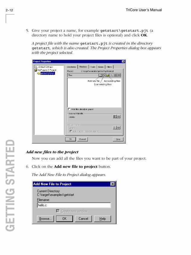
5. Give your project a name, for example getstart\getstart.pjt (adirectory name to hold your project files is optional) and click OK.
A project file with the name getstart.pjt is created in the directorygetstart, which is also created. The Project Properties dialog box appearswith the project selected.
Add new files to the project
Now you can add all the files you want to be part of your project.
6. Click on the Add new file to project button.
The Add New File to Project dialog appears.

Getting Started 2−13
• • • • • • • •
7. Enter a new filename (for example hello.c) and click OK.
A new empty file is created and added to the project. Repeat steps 6 and 7 ifyou want to add more files.
8. Click OK.
The new project is now open. EDE loads the new file(s) in the editor inseparate document windows.
EDE automatically creates a makefile for the project (in this casegetstart.mak). This file contains the rules to build your application.EDE updates the makefile every time you modify your project.
Edit your files
9. As an example, type the following C source in the hello.c documentwindow:
#include <stdio.h>
void main(void){ printf("Hello World!\n");}
10. Click on the Save the changed file <Ctrl−S> button.
EDE saves the file.

TriCore User’s Manual2−14GET
TING
STA
RTED
2.6 SET OPTIONS FOR THE TOOLS IN THE TOOLCHAIN
The next step in the process of building your application is to select atarget processor and specify the options for the different parts of thetoolchain, such as the C and/or C++ compiler, assembler, linker anddebugger.
Select a target processor
1. From the Project menu, select Project Options...
The Project Options dialog appears.
2. Expand the Processor entry and select Processor Definition.
3. In the Target processor list select (for example) TC11IB.
4. Click OK to accept the new project settings.
Set tool options
1. From the Project menu, select Project Options...
The Project Options dialog appears. Here you can specify options that arevalid for the entire project. To overrule the project options for the currentlyactive file instead, from the Project menu select Current File Options...

Getting Started 2−15
• • • • • • • •
2. Expand the C Compiler entry.
The C Compiler entry contains several pages where you can specify Ccompiler settings.
3. For each page make your changes. If you have made all changes click OK.
The Cancel button closes the dialog without saving your changes. Withthe Defaults button you can restore the default project options (for thecurrent page, or all pages in the dialog).
4. Make your changes for all other entries (Assembler, Linker, CrossView Pro)of the Project Options dialog in a similar way as described above for the Ccompiler.
If available, the Options string field shows the command line optionsthat correspond to your graphical selections.

TriCore User’s Manual2−16GET
TING
STA
RTED
2.7 BUILD YOUR APPLICATION
If you have set all options, you can actually compile the file(s). This resultsin an absolute ELF/DWARF object file which is ready to be debugged.
Build your Application
To build the currently active project:
• Click on the Execute ’Make’ command button.
The file is compiled, assembled, linked and located. The resulting file isgetstart.elf.
The build process only builds files that are out−of−date. So, if you clickMake again in this example nothing is done, because all files areup−to−date.
Viewing the Results of a Build
Once the files have been processed, you can see which commands havebeen executed (and inspect generated messages) by the build process inthe Build tab of the Output window.
This window is normally open, but if it is closed you can open it byselecting the Output menu item in the Window menu.
Compiling a Single File
1. Select the window (document) containing the file you want to compile orassemble.
2. Click on the Execute ’Compile’ command button. The following buttonis the execute Compile button which is located in the toolbar.
If you selected the file hello.c, this results in the compiled and assembledfile hello.o.

Getting Started 2−17
• • • • • • • •
Rebuild your Entire Application
If you want to compile, assemble and link/locate all files of your projectfrom scratch (regardless of their date/time stamp), you can perform arebuild.
• Click on the Execute ’Rebuild’ command button. The followingbutton is the execute Rebuild button which is located in the toolbar.
2.8 HOW TO BUILD YOUR APPLICATION ON THECOMMAND LINE
If you are not using EDE, you can build your entire application on thecommand line. The easiest way is to use the control program cctc.
1. In a text editor, write the file hello.c with the following contents:
#include <stdio.h>
void main(void){ printf("Hello World!\n");}
2. Build the file getstart.elf:
cctc −ogetstart.elf hello.c −v
The control program calls all tools in the toolchain. The −v option shows allthe individual steps. The resulting file is getstart.elf.

TriCore User’s Manual2−18GET
TING
STA
RTED
2.9 DEBUG GETSTART.ELF
The application getstart.elf is the final result, ready for executionand/or debugging. The debugger uses getstart.elf for debugging butneeds symbolic debug information for the debugging process. Thisinformation must be included in getstart.elf and therefore you needto compile and assemble hello.c once again.
cctc −g −ogetstart.elf hello.c
Now you can start the debugger with getstart.elf and see how itexecutes.
Start CrossView Pro• Click on the Debug application button.
CrossView Pro is launched. CrossView Pro will automatically download thefile getstart.elf for debugging.
See the CrossView Pro Debugger User’s Manual for more information.

3
TRICOREC LANGUAGE
CHAPTER

TriCore User’s Manual3−2C LA
NGUA
GE
3
CHAPTER

TriCore C Language 3−3
• • • • • • • •
3.1 INTRODUCTION
The TASKING C cross−compiler (ctc) fully supports the ISO C standardand adds extra possibilities to program the special functions of the TriCore.
In addition to the standard C language, the compiler supports thefollowing:
• extra data types, like __fract, __laccum and __packb
• intrinsic (built−in) functions that result in TriCore specific assemblyinstructions
• pragmas to control the compiler from within the C source
• predefined macros
• the possibility to use assembly instructions in the C source
• keywords to specify memory types for data and functions
• attributes to specify alignment and absolute addresses
All non−standard keywords have two leading underscores (__).
In this chapter the TriCore specific characteristics of the C language aredescribed, including the above mentioned extensions.
3.2 DATA TYPES
3.2.1 FUNDAMENTAL DATA TYPES
The TriCore architecture defines the following fundamental data types:
• An 8−bit byte
• A 16−bit short
• A 32−bit word
• A 64−bit double word
The next table shows the mapping between these fundamental data typesand the C language data types.
TriCore User’s Manual3−4C LA
NGUA
GE
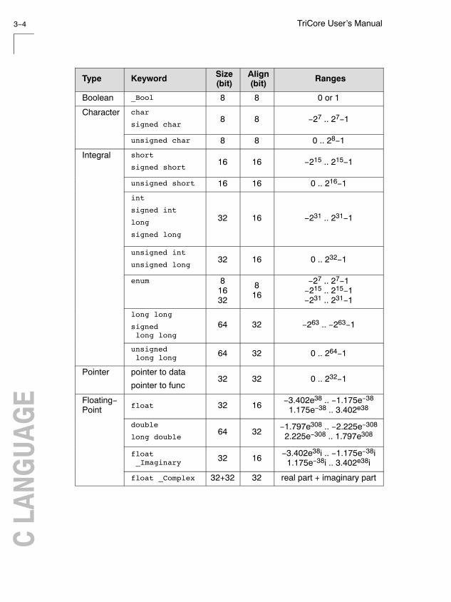
Type Keyword Size(bit)
Align(bit) Ranges
Boolean _Bool 8 8 0 or 1
Character char
signed char8 8 −27 .. 27−1
unsigned char 8 8 0 .. 28−1
Integral short
signed short16 16 −215 .. 215−1
unsigned short 16 16 0 .. 216−1
int
signed int
long
signed long
32 16 −231 .. 231−1
unsigned int
unsigned long32 16 0 .. 232−1
enum 81632
816
−27 .. 27−1−215 .. 215−1−231 .. 231−1
long long
signed long long
64 32 −263 .. −263−1
unsigned long long 64 32 0 .. 264−1
Pointer pointer to data
pointer to func32 32 0 .. 232−1
Floating−Point float 32 16 −3.402e38 .. −1.175e−38
1.175e−38 .. 3.402e38
double
long double64 32 −1.797e308 .. −2.225e−308
2.225e−308 .. 1.797e308
float _Imaginary 32 16 −3.402e38i .. −1.175e−38i
1.175e−38i .. 3.402e38i
float _Complex 32+32 32 real part + imaginary part

TriCore C Language 3−5
• • • • • • • •
RangesAlign(bit)
Size(bit)KeywordType
double/long double _Imaginary
64 32 −1.797e308i .. −2.225e−308i2.225e−308i .. 1.797e308i
double/long double _Complex
64+64 32 real part + imaginary part
Table 3−1: Data Types
When you use the enum type, the compiler will use the smallest sufficientinteger type, unless you use compiler option −−integer−enumeration(always use 32−bit integers for enumeration).
See also the TriCore Embedded Applications Binary Interface (EABI).
3.2.2 FRACTIONAL DATA TYPES
The TASKING TriCore C compiler ctc additionally supports the followingfractional types:
Type Keyword Size(bit)
Align(bit) Ranges
Fract __sfract 16 16 [−1, 1>
__fract 32 32 [−1, 1>
Accum __laccum 64 32 [−131072,131072>
Table 3−2: Fractional Data Types
The __sfract type has 1 sign bit + 15 mantissa bitsThe __fract type has 1 sign bit + 31 mantissa bitsThe __laccum type has 1 sign bit + 17 integral bits + 46 mantissa bits.
The __accum type is only included for compatibility reasons and ismapped to __laccum.
The TASKING C compiler ctc fully supports fractional data types whichallow you to use normal expressions:
TriCore User’s Manual3−6C LA
NGUA
GE
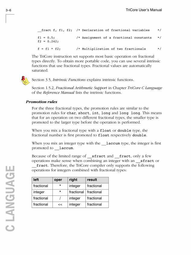
__fract f, f1, f2; /* Declaration of fractional variables */
f1 = 0.5; /* Assignment of a fractional constants */f2 = 0.242;
f = f1 * f2; /* Multiplication of two fractionals */
The TriCore instruction set supports most basic operation on fractionaltypes directly. To obtain more portable code, you can use several intrinsicfunctions that use fractional types. Fractional values are automaticallysaturated.
Section 3.5, Intrinsic Functions explains intrinsic functions.
Section 1.5.2, Fractional Arithmetic Support in Chapter TriCore C Languageof the Reference Manual lists the intrinsic functions.
Promotion rules
For the three fractional types, the promotion rules are similar to thepromotion rules for char, short, int, long and long long. This meansthat for an operation on two different fractional types, the smaller type ispromoted to the larger type before the operation is performed.
When you mix a fractional type with a float or double type, thefractional number is first promoted to float respectively double.
When you mix an integer type with the __laccum type, the integer is firstpromoted to __laccum.
Because of the limited range of __sfract and __fract, only a fewoperations make sense when combining an integer with an __sfract or__fract. Therefore, the TriCore compiler only supports the followingoperations for integers combined with fractional types:
left oper right result
fractional * integer fractional
integer * fractional fractional
fractional / integer fractional
fractional << integer fractional

TriCore C Language 3−7
• • • • • • • •
resultrightoperleft
fractional >> integer fractional
fractional: __sfract, __fract
integer: char, short, int, long, long long
Table 3−3: Fractional operations for integers with fractional types
3.2.3 BIT DATA TYPE
The TASKING TriCore C compiler ctc additionally supports the bit datatype:
Type Keyword Size(bit)
Align(bit) Range
Bit __bit 8 8 0 or 1
Table 3−4: Bit Data Type
The TriCore instruction set supports some operations of the __bit typedirectly.
The following rules apply to __bit type variables:
• A __bit type variable is always unsigned.
• A __bit type variable can be exchanged with all other type−variables.The compiler generates the correct conversion.
A __bit type variable is like a boolean. Therefore, if you convert anint type variable to a __bit type variable, it becomes 1 (true) if theinteger is not equal to 0, and 0 (false) if the integer is 0. The next twoC source lines have the same effect:
bit_variable = int_variable; bit_variable = int_variable ? 1 : 0;
• Pointer to __bit is not allowed when it has the __atbit() qualifier.
• The __bit type is allowed as a structure member.
• A __bit type variable is allowed as a parameter of a function.
• A __bit type variable is allowed as a return type of a function.
• A __bit typed expression is allowed as switch expression.
• The sizeof of a __bit type is 1.

TriCore User’s Manual3−8C LA
NGUA
GE
• Global or static __bit type variable can be initialized.
• A __bit type variable can be declared absolute using the __atbitattribute. See section 3.3.2 Declare a Data Object at an AbsoluteAddress: __at() and __atbit() for more details.
• A __bit type variable can be declared volatile.
Promotion Rules
For the __bit type, the promotion rules are similar to the promotion rulesfor char, short, int, long and long long.
3.2.4 PACKED DATA TYPES
The TASKING TriCore C compiler ctc additionally supports the followingpacked types:
Type Keyword Size(bit)
Align(bit) Ranges
Packed __packb
signed __packb32 16 4x: −27 .. 27−1
unsigned __packb 32 16 4x: 0 .. 28−1
__packhw
signed __packhw32 16 2x: −215 .. 215−1
unsigned __packhw 32 16 2x: 0 .. 216−1
Table 3−5: Fractional Data Types
A __packb value consists of four signed or unsigned char values.A __packhw value consists of two signed or unsigned short values.
The TriCore instruction set supports a number of arithmetic operations onpacked data types directly. For example, the following function:
__packb add4 ( __packb a, __packb b ){ return a + b;}

TriCore C Language 3−9
• • • • • • • •
results into the following assembly code:
add4: add.b d2,d4,d5 ret16
Section 3.5, Intrinsic Functions explains intrinsic functions.
Section 1.5.3, Packed Data Type Support in Chapter TriCore C Language ofthe Reference Manual lists the intrinsic functions.
Halfword Packed Unions and Structures
To minimize space consumed by alignment padding with unions andstructures, elements follow the minimum alignment requirements imposedby the architecture. The TriCore arichitecture supports access to 32−bitinteger variables on halfword boundaries.
Because only doubles, circular buffers, __laccum or pointers require thefull word access, structures that do not contain members of these types areautomatically halfword (2−bytes) packed.
Structures and unions that are divisible by 64−bit or contain members thatare divisible by 64−bit, are word packed to allow efficient access throughLD.D and ST.D instructions. These load and store operations require wordaligned structures that are divisible by 64−bit. If necessary, 64−bit divisiblestructure elements are aligned or padded to make the structure 64−bitaccessible.
With #pragma pack 2 you can disable the LD.D/ST.D structure andunion copy optimization to ensure halfword structure and union packingwhen possible. This "limited" halfword packing only supports structuresand unions that do not contain double, circular buffer, __laccum orpointer type members and that are not qualified with #pragma align toget an alignment larger than 2−byte. With #pragma pack 0 you turn offhalfword packing again.
#pragma pack 2typedef struct { unsigned char uc1; unsigned char uc2; unsigned short us1; unsigned short us2; unsigned short us3;} packed_struct;#pragma pack 0

TriCore User’s Manual3−10C LA
NGUA
GE
When you place a #pragma pack 0 before a structure or union, itsalignment will not be changed:
#pragma pack 0packed_struct pstruct;
The alignment of data sections and stack can also affect the alignment ofthe base address of a halfword packed structure. A halfword packedstructure can be aligned on a halfword boundary or larger alignment.When located on the stack or at the beginning of a section, the alignmentbecomes a word, because of the minimum required alignment of datasections and stack objects. A stack or data section can contain any type ofobject. To avoid wrong word alignment of objects in the section, thesection base is also word aligned.
3.3 MEMORY QUALIFIERS
You can use static memory qualifiers to allocate static objects in aparticular part of the addressing space of the processor.
In addition, you can place variables at absolute addresses with thekeyword __at(). If you declare an integer at an absolute address, youcan declare a single bit of that variable as bit variable with the keyword__atbit().
3.3.1 DECLARE A DATA OBJECT IN A SPECIAL PARTOF MEMORY
With a memory qualifier you can declare a variable in a specific part of theaddressing space. You can use the following memory qualifiers:
__near The declared data object will be located in the first 16 kB ofa 256 MB block. These parts of memory are directlyaddressable with the absolute addressing mode (see section4.4.1, Operands and Addressing Modes, in Chapter TriCoreAssembly Language).
__far The data object can be located anywhere in the indirectaddressable memory region.

TriCore C Language 3−11
• • • • • • • •
If you do not specify __near or __far, the compiler chooses where toplace the declared object. With the compiler option −N (maximum size inbytes for data elements that are default located in __near sections) youcan specify the size of data objects which the compiler then by defaultplaces in near memory.
__a0 The data object is located in a section that is addressable witha sign−extended 16−bit offset from address register A0.
__a1 The data object is located in a section that is addressable witha sign−extended 16−bit offset from address register A1.
__a8 The data object is located in a section that is addressable witha sign−extended 16−bit offset from address register A8.
__a9 The data object is located in a section that is addressable witha sign−extended 16−bit offset from address register A9.
Address registers A0, A1, A8, and A9 are designated as system globalregisters. They are not part of either context partition and are notsaved/restored across calls. They can be protected against write access byuser applications.
By convention, A0 and A1 are reserved for compiler use, while A8 and A9are reserved for OS or application use. A0 is used as a base pointer to thesmall data section, where global data elements can be accessed usingbase + offset addressing. A0 is initialized by the execution environment.
A1 is used as a base pointer to the literal data section. The literal datasection is a read−only data section intended for holding address constantsand program literal values. Like A0, it is initialized by the executionenvironment.
As noted, A8 and A9 are reserved for OS use, or for application use incases where the application and OS are tightly coupled.
All these memory qualifiers (__near, __far, __a0, __a1, __a8 and__a9) are related to the object being defined, they influence where theobject will be located in memory. They are not part of the type of theobject defined. Therefore, you cannot use these qualifiers in typedefs, typecasts or for members of a struct or union.

TriCore User’s Manual3−12C LA
NGUA
GE
Examples:
To declare a fast accessible integer in directly addressable memory:
int __near Var_in_near;
To allocate a pointer in far memory (the compiler will not use absoluteaddressing mode):
__far int *Ptr_in_far;
To declare and initialize a string in A0 memory:
char __a0 string[] = "TriCore";
If you use the __near memory qualifier, the compiler generates fasteraccess code for those (frequently used) variables. Pointers are always32−bit.
Functions are by default allocated in ROM. In this case you can omit the amemory qualifier. You cannot use memory qualifiers for function returnvalues.
Some examples of using memory qualifiers:
int __near *p; /* pointer to int in __near memory (pointer has 32−bit size) */int __far *g; /* pointer to int in __far memory (pointer has 32−bit size) */
g = p; /* the compiler issues a warning */
You cannot use memory qualifiers in structure declarations:
struct S { __near int i; /* put an integer in near memory: Incorrect ! */ __far int *p; /* put an integer pointer in far memory: Incorrect ! */ }
If a library function declares a variable in near memory and you try toredeclare the variable in far memory, the linker issues an error:
extern int _near foo; /* extern int in near memory*/
int __far foo; /* int in far memory */

TriCore C Language 3−13
• • • • • • • •
The usage of the variables is always without a storage specifier:
char __near example;example = 2;
The generated assembly would be:
mov16 d15,2st.b example,d15
All allocations with the same storage specifiers are collected in units called’sections’. The section with the __near attribute will be located within thefirst 16 kB of of each 256 MB block.
With the linker it is possible to control the location of sections manually.See Chapter 7 Linker.
3.3.2 DECLARE A DATA OBJECT AT AN ABSOLUTEADDRESS: __at() AND __atbit()
Just like you can declare a variable in a specific part of memory, you canalso place an object at an absolute address in memory. This may be usefulto interface with other programs using fixed memory schemes, or to accessspecial function registers.
With the attribute __at() you can specify an absolute address.
Examples
int myvar __at(0x100);
The variable myvar is placed at address 0x100.
unsigned char Display[80*24] __at( 0x2000 )
The array Display is placed at address 0x2000. In the generatedassembly, an absolute section is created. On this position space is reservedfor the variable Display.

TriCore User’s Manual3−14C LA
NGUA
GE
Restrictions
Take note of the following restrictions if you place a variable at anabsolute address:
• You can place only global variables at absolute addresses. Parametersof functions, or automatic variables within functions cannot be placedat absolute addresses.
• When declared extern, the variable is not allocated by the compiler.When the same variable is allocated within another module but on adifferent address, the compiler, assembler or linker will not notice,because an assembler external object cannot specify an absoluteaddress.
• When the variable is declared static, no public symbol will begenerated (normal C behavior).
• You cannot place functions at absolute addresses.
• Absolute variables cannot overlap each other. If you declare twoabsolute variables at the same address, the assembler and / or linkerissues an error. The compiler does not check this.
• When you declare the same absolute variable within two modules, thisproduces conflicts during link time (except when one of the modulesdeclares the variable ’extern’).
Declaring a bit variable with __atbit()
If you have defined a 32−bits base variable (int, long) you can declare asingle bit of that variable as a bit variable with the keyword __atbit().The syntax is:
__atbit( name, offset )
name is the name of an integer variable in which the bit is located. offset(range 0−31) is the bit−offset within the variable.
If you have defined an absolute integer variable with the keyword__at(), you can declare a single bit of that variable as an absolute bitvariable with __atbit().
Example
int bw __at(0x100);__bit myb __atbit( bw, 3 );

TriCore C Language 3−15
• • • • • • • •
Note that the keyword __bit is used to declare the variable myb as a bit,and that the keyword __atbit() is used to declare that variable at anabsolute offset in variable bw.
See also section 3.2.3, Bit Data Type.
Restrictions
• You can only use the __atbit() qualifier on variables of type __bit.
• When a variable is __atbit() qualified it represents an alias of a bitin another variable. Therefore, it cannot be initialized.
• You can only use the __atbit() qualifier on variables which haveeither a global scope or file scope.
3.4 DATA TYPE QUALIFIERS
3.4.1 CIRCULAR BUFFERS: __circ
The TriCore core has support for implementing specific DSP tasks, such asfinite impulse response (FIR) and infinite impulse response (IIR) filters andfast Fourier transforms (FFTs). For the FIR and IIR filters the TriCorearchitecture supports the circular addressing mode and for the FFT thebit−reverse addressing mode. The TriCore C compiler supports circularbuffers for these DSP tasks. This way, the TriCore C compiler makeshardware features available at C source level instead of at assembly levelonly.
A circular buffer is a linear (one dimensional) array that you can access bymoving a pointer through the data. The pointer can jump from the lastlocation in the array to the first, or vice−versa (the pointer wraps−around).This way the buffer appears to be continuous. The TriCore C compilersupports the __circ keyword (circular addressing mode) for this type ofbuffer.
Example: __circ
__fract __circ circbuffer[10];__fract __circ *ptr_to_circbuffer = circbuffer;

TriCore User’s Manual3−16C LA
NGUA
GE
Here, circbuffer is declared as a circular buffer. The compiler aligns thebase address of the buffer on the access width (in this example an int, so4 bytes). The compiler keeps the buffer size and uses it to control pointerarithmetic of pointers that are assigned to the buffer later.
You can perform operations on circular pointers with the usual C pointerarithmetic with the difference that the pointer will wrap. When you accesthe circular buffer with a circular pointer, it wraps at the buffer limits.Circular pointer variables are 64 bits in size.
Example:
while( *Pptr_to_circbuf++ );
Indexing in the circular buffer, using an integer index, is treated equally toindexing in a non−circular array.
Example:
int i = circbuf[3];
The index is not calculated modulo; indexing outside the array boundariesyields undefined results.
If you want to initialize a circular pointer with a dynamically allocatedbuffer at run−time, you should use the intrinsic function __initcirc():
#define N 100unsigned short s = sizeof(__fract);__fract *ptr_to_circbuf = calloc( N, s );circbuf = __initcirc( ptr_to_circbuf, N * s, 0 * s );
3.4.2 DECLARE AN SFR BIT FIELD: __sfrbit16 AND__sfrbit32
With the data type qualifiers __sfrbit16 and __sfrbit32 you candeclare bit fields in special function registers.
According to the TriCore Embedded Applications Binary Interface, ’normal’bit fields are accessed as char, short or int. Thus:
• fields with a width of 8−bits or less impose only byte alignments
• fields with a width from 9 to 16 bits impose halfword alignment
• fields with a width from 17 to 32 bits impose word alignment

TriCore C Language 3−17
• • • • • • • •
If you declare bit fields in special function registers, this behavior is notalways desired: some special function registers require 16−bit or 32−bitaccess. To force 16−bit or 32−bit access, you can use the data typequalifiers __sfrbit16 and __sfrbit32.
For each supported target, a special function register file(regcpu_name.sfr) is delivered with the TriCore toolchain. In normalcircumstances you should not need to declare SFR bit fields.
Example
The next example is part of an SFR file and illustrates the declaration of aspecial function register using the data type qualifier __sfrbit32:
typedef volatile union{ struct { unsigned __sfrbit32 SRPN : 1; /* BCU Service Priority Number */ unsigned int : 2; unsigned __sfrbit32 TOS : 2; /* BCU Type−of−Service Control */ unsigned __sfrbit32 SRE : 1; /* BCU Service Request Enable Control */ unsigned __sfrbit32 SRR : 1; /* BCU SerService Request Flag */ unsigned __sfrbit32 CLRR : 1; /* BCU Request Clear Bit */ unsigned __sfrbit32 SETR : 1; /* BCU Request Set Bit */ unsigned int : 16; } B;
int I;} BCU_SRC_type;
#define BCU_SRC (*(BCU_SRC_type*)(0xF00002FC)) /* BCU Service Request Node */
You can now access the register and bit fields as follows:
#include <regtc10gp.sfr>
BCU_SRC.I |= 0xb32a; /* access BCU Service Request Control register as a whole */
BCU_SRC.B.SRE = 0x1; /* access SRE bit field of BCU Service Request Control register */

TriCore User’s Manual3−18C LA
NGUA
GE
Restrictions
You can use the __sfrbit32 and __sfrbit16 data type qualifiers onlyfor int types. The compiler issues an error if you use for example__sfrbit32 char x : 8;
When you use the __sfrbit32 and __sfrbit16 data type qualifiers forother types than a bit field, the compiler ignores this without a warning.For example, __sfrbit32 int global; is equal to int global;.
Structures or unions that contain a member qualified with __sfrbit16,are zero padded to complete a halfword if necessary. The structure orunion will be halfword aligned.Structures or unions that contain a member qualified with __sfrbit32,are zero padded to complete a full word if necessary. The structure orunion will be word aligned.
3.4.3 SATURATION: __sat
When a variable is declared with the type qualifier __sat, all operationson that variable will be performed using saturating arithmetic. When anoperation is performed on a plain variable and a __sat variable, the__sat takes precedence, and the operation is done using saturatingarithmetic. The type of the result of such an operation also includes thequalifier __sat, so that another operation on the result will also besaturated. In this respect, the behavior of the type qualifier __sat iscomparable to the unsigned keyword. You can overrule this behavior byinserting type casts with or without the type qualifier __sat in anexpression.
You can only use the type qualifier __sat on type int (fractional typesare always saturated.
Care should be taken when combining signed and unsigned integers,since no saturation between signed and unsigned is done.
Examples:
_sat int si = 0x7FFFFFFF; int i = 0x12345; unsigned int ui = 0xFFFFFFFF;
si + i // a saturated addition is performed, // yielding a saturated int

TriCore C Language 3−19
• • • • • • • •
si + ui // a saturated unsigned addition is performed, // yielding a saturated unsigned int
i + ui // a normal unsigned addition is performed, // yielding an unsigned int
3.5 INTRINSIC FUNCTIONS
Some specific TriCore assembly instructions have no equivalence in C.Intrinsic functions give the possibility to use these instructions. Intrinsicfunctions are predefined functions that are recognized by the compiler.The compiler then generates the most efficient assembly code for thesefunctions.
The compiler always inlines the corresponding assembly instructions in theassembly source rather than calling the function. This avoids unnecessaryparameter passing and register saving instructions which are normallynecessary when a function is called.
Intrinsic functions produce very efficient assembly code. Though it ispossible to inline assembly code by hand, registers are used even moreefficient by intrinsic functions. At the same time your C source remainsvery readable.
You can use intrinsic functions in C as if they were ordinary C (library)functions. All intrinsics begin with a double underscore character. Thefollowing example illustrates the use of an intrinsic function and itsresulting assembly code.
x = __min( 4,5 );
The resulting assembly code is inlined rather than being called:
mov16 d2,#4min d2,d2,#5
The intrinsics cover the following subjects:
• Minimum and maximum of (short) integers
• Fractional data type support
• Packed data type support
• Interrupt handling
• Insert single assembly instruction
• Register handling

TriCore User’s Manual3−20C LA
NGUA
GE
• Insert / extract bitfields and bits
• Miscellaneous
For extended information about all available intrinsic functions, refer tosection 1.5, Intrinsic Functions, in Chapter TriCore C Language of theReference Manual.
3.6 USING ASSEMBLY IN THE C SOURCE: __asm()
With the __asm() keyword you can use assembly instructions in the Csource and pass C variables as operands to the assembly code. Be awarethat C modules that contain assembly are not portable and harder tocompile in other environments.
The compiler does not interpret assembly blocks but passes the assemblycode to the assembly source file. Possible errors can only be detected bythe assembler.
General syntax of the __asm keyword
__asm( "instruction_template" [ : output_param_list [ : input_param_list [ : register_save_list]]] );
instruction_template Assembly instructions that may containparameters from the input list or output list inthe form: %parm_nr
%parm_nr[.regnum] Parameter number in the range 0 .. 9. With theoptional .regnum you can access an individualregister from a register pair or register quad. Forexample, with register pair d0/d1, .0 selectsregister d0.
output_param_list [[ "=[&]constraint_char"(C_expression)],...]
input_param_list [[ "constraint_char"(C_expression)],...]
& Says that an output operand is written to beforethe inputs are read, so this output must not bethe same register as any input.

TriCore C Language 3−21
• • • • • • • •
constraint _char Constraint character: the type of register to beused for the C_expression.(see table 3−6)
C_expression Any C expression. For output parameters it mustbe an lvalue, that is, something that is legal tohave on the left side of an assignment.
register_save_list [["register_name"],...]
register_name Name of the register you want to reserve.
Typical example: multiplying two C variables using assemblyint a,b,result;
void main( void ){ __asm("mul\t%0,%1,%2" : "=d"(result) : "d"(a), "d"(b) );}
generated code:
ld.w d15,ald.w d0,bmul d15,d15,d0st.w result,d15
%0 corresponds to the first C variable, %1 corresponds to the second andso on. The escape sequence \t generates a tab.
Specifying registers for C variables
With a constraint character you specify the register type for a parameter.In the example above, the d is used to force the use of data registers forthe parameters a, b and result.
You can reserve the registers that are used in the assembly instructions,either in the parameter lists or in the reserved register list(register_save_list). The compiler takes account of these lists, so nounnecessary register saves and restores are placed around the inlineassembly instructions.

TriCore User’s Manual3−22C LA
NGUA
GE
Constraintcharacter
Type Operand Remark
a Address register a0 .. a15
d Data register d0 .. d15
e Data register pair e0,e2,..,e14 e0 = pair d0/d1, e2 = d2/d3, ...
m Memory variable Stack or memory operand
number Type of operand itis associated with
same as%number
Indicates that %number andnumber are the same register.
Table 3−6: Available input/output operand constraints
Loops and conditional jumps
The compiler does not detect loops with multiple __asm statements or(conditional) jumps across __asm statements and will generate incorrectcode for the registers involved.
If you want to create a loop with __asm, the whole loop must becontained in a single __asm statement. The same counts for (conditional)jumps. As a rule of thumb, all references to a label in an __asm statementmust be in that same statement.
Example 1: no input or output
A simple example without input or output parameters. You can just outputany assembly instruction:
__asm( "nop" );
Generated code:
nop

TriCore C Language 3−23
• • • • • • • •
Example 2: using output parameters
Assign the result of inline assembly to a variable. With the constraint d adata register is chosen for the parameter; the compiler decides which dataregister it uses. The %0 in the instruction template is replaced with thename of this data register. Finally, the compiler generates code to assignthe result to the output variable.
int result;
void main( void ){ __asm( "mov %0,#0xFF" : "=d"(result));}
Generated assembly code:
mov d15,#0xFFst.w result,d15
Example 3: using input and output parameters
Multiply two C variables and assign the result to a third C variable. Datatype registers are necessary for the input and output parameters (constraintd, %0 for result, %1 for a and %2 for b in the instruction template). Thecompiler generates code to move the input expressions into the inputregisters and to assign the result to the output variable.
int a, b, result;
void multiply( void ){ __asm( "mul %0, %1, %2": "=d"(result): "d"(a), "d"(b) );}
void main(void){ multiply();}
Generated assembly code:
multiply: ld.w d15,a ld.w d0,b mul d15, d15, d0 st.w result,d15
main: j multiply

TriCore User’s Manual3−24C LA
NGUA
GE
Example 4: reserve registers
If you use registers in the __asm statement, reserve them. Same asExample 3, but now register d0 is a reserved register. You can do this byadding a reserved register list (: "d0") (sometimes referred to as ’clobberlist’). As you can see in the generated assembly code, register d0 is notused (the first register used is d1).
int a, b, result;
void multiply( void ){ __asm( "mul %0, %1, %2": "=d"(result): "d"(a), "d"(b) : "d0" );}
Generated assembly code:
ld.w d15,ald.w d1,bmul d15, d15, d1st.w result,d15
Example 5: input and output are the same
If the input and output must be the same you must use a numberconstraint. The following example inverts the value of the input variableivar and returns this value to ovar. Since the assembly instruction notuses only one register, the return value has to go in the same place as theinput value. To indicate that ivar uses the same register as ovar, theconstraint ’0’ is used which indicates that ivar also corresponds with %0.
int ovar;
void invert(int ivar){ __asm ("not %0": "=d"(ovar): "0"(ivar) );}
void main(void){ invert(255);}
Generated assembly code:
invert: not d4 st.w ovar,d4

TriCore C Language 3−25
• • • • • • • •
main: mov d4,#255 j invert
Example 6: writing your own intrinsic function
Because you can use any assembly instruction with the __asm keyword,you can use the __asm keyword to create your own intrinsic functions.The essence of an intrinsic function is that it is inlined.
First write a function with assembly in the body using the keyword __asm.We use the multiply routine from Example 3.
Next make sure that the function is inlined rather than being called. Youcan do this with the function qualifier inline. This qualifier is discussedin more detail in section 3.9.1, Inlining Functions.
int a, b, result;
inline void __my_mul( void ){ __asm( "mul %0, %1, %2": "=d"(result): "d"(a), "d"(b) );}
void main(void){ // call to function __my_mul __my_mul();}
Generated assembly code:
main: ; __my_mul code is inlined here ld.w d15,a ld.w d0,b mul d15, d15, d0 st.w result,d15
As you can see, the generated assembly code for the function __my_mul isinlined rather than called.

TriCore User’s Manual3−26C LA
NGUA
GE
Example 7: accessing individual registers in a register pair
You can access the individual registers in a register pair by adding a ’.’after the operand specifier in the assembly part, followed by the index inthe register pair.
int f1, f2;
void foo(double d){ __asm ("ld.w %0, %2.0\n" "\tld.w %1, %2.1":"=&d"(f1),"=d"(f2):"e"(d) );}
The first ld.w instruction uses index #0 of argument 2 (which is a doubleplaced in a DxDx register) and the second ld.w instruction uses index #1.The input operand is located in register pair d4/d5. The assembly outputbecomes:
ld.w d15, d4 ld.w d0, e4,1 ; note that e4,1 corresponds to d5 st.w f1,d15 st.w f2,d0 ret16
If the index is not a valid index (for example, the register is not a registerpair, or the argument has not a register constraint), the ’.’ is passed into theassembly output. This way you can still use the ’.’ in assembly instructions.
3.7 CONTROLLING THE COMPILER: PRAGMAS
Pragmas are keywords in the C source that control the behavior of thecompiler. Pragmas sometimes overrule compiler options. In generalpragmas give directions to the code generator of the compiler.
The syntax is:
#pragma pragma−spec [ON | OFF | RESTORE | DEFAULT]
or:
_Pragma("pragma−spec [ON | OFF | RESTORE | DEFAULT]")

TriCore C Language 3−27
• • • • • • • •
For example, you can set a compiler option to specify which optimizationsthe compiler should perform. With the #pragma optimize flags youcan set an optimization level for a specific part of the C source. Thisoverrules the general optimization level that is set in the compiler optionsdialog (command line option −O).
Some pragmas have an equivalent command line option. This is useful ifyou want to overrule certain keywords in the C source without the need tochange the C source itself.
See section 5.1, Compiler Options, in Chapter 5, Tool Options, of theReference Manual.
The compiler recognizes the following pragmas, other pragmas areignored.
Pragma name Description
alias symbol=defined−symbol Defines an alias for a symbol
align {n|restore} Specifies object alignment.See compiler option −−align insection 5.1, Compiler Options inChapter Tool Options of theReference Manual.
clearnoclear
Specifies ’clearing’ ofnon−initialized static/publicvariables
CPU_functional_problemDMU_functional_problem
Use software workarounds for thespecified functional problem.See compiler option−−silicon−bug in section 5.1,Compiler Options in Chapter ToolOptions of the Reference Manual.
default_a0_size value Threshold for ’__a0’ allocation
default_a1_size value Threshold for ’__a1’ allocation
default_near_size value Threshold for ’__near’ allocation
extension isuffix Enables the language extension tospecify imaginary floating−pointconstants by adding an ’i’ to theconstant
extern symbol Forces an external reference

TriCore User’s Manual3−28C LA
NGUA
GE
DescriptionPragma name
for_constant_data_use_memoryfor_extern_data_use_memoryfor_initialized_data_use_memoryfor_uninitialized_data_use_memory
Specify a memory for the type ofdata mentioned in the pragma. Youcan specify near, far, a0, a8, a9 (ora1 only for constant data)
immediate_in_code Forces the compiler to encode allimmediate values into instructions.See compiler option−−immediate−in−code in section5.1, Compiler Options in ChapterTool Options of the ReferenceManual.
indirect Generates code for indirectfunction calling. See compileroption −−indirect in section 5.1,Compiler Options in Chapter ToolOptions of the Reference Manual.
indirect−runtime Generates code for indirectfunction calling to all runtimefunctions. See compiler option−−indirect−runtime in section 5.1,Compiler Options in Chapter ToolOptions of the Reference Manual.
inlinenoinlinesmartinline
Specifies function inlining.See section 3.9.1, InliningFunctions.
macronomacro
Turns macro expansion on(default) or off.
message "string" ... Emits a message to standardoutput
object_comment "string" Generates a .comment sectionwith string in the .src file whichthen appears in the object file.
optimize flagsendoptimize
Controls compiler optimizations.See section 5.3, CompilerOptimizations in Chapter Using theCompiler
pack {2|0} Specifies packing of structures.See section 3.2.4, Packed DataTypes.

TriCore C Language 3−29
• • • • • • • •
DescriptionPragma name
section code_initsection const_initsection vector_initsection data_overlay
At startup copies correspondingsections to RAM for initialization
Allow overlaying data sections
section type[=]"name"section all
section_name_with_modulesection_name_with_symbolsection_per_data_object
Changes section names.See section 3.10, CompilerGenerated Sections and compileroption −R in section 5.1, CompilerOptions in Chapter Tool Options ofthe Reference Manual
sourcenosource
Specifies which C source linesmust be shown in assemblyoutput.See compiler option −s in section5.1, Compiler Options in ChapterTool Options of the ReferenceManual.
switch {auto|jumptab| linear|lookup|restore}
Specifies switch statement.See section 3.11, SwitchStatement
tradeoff level Specify tradeoff between speed (0)and size (4). See compiler option−t in section 5.1, Compiler Optionsin Chapter Tool Options of theReference Manual.
warning [number,...] Disables warning messages. Seecompiler option −w in section 5.1,Compiler Options in Chapter ToolOptions of the Reference Manual.
weak symbol Marks a symbol as ’weak’
Table 3−7: Pragmas

TriCore User’s Manual3−30C LA
NGUA
GE
3.8 PREDEFINED MACROS
In addition to the predefined macros required by the ISO C standard, theTASKING TriCore C compiler supports the predefined macros as defined inTable 3−8. The macros are useful to create conditional C code.
Macro Description
__DOUBLE_FP__ Defined when you do not use compiler option −F(Treat double as float)
__SINGLE_FP__ Defined when you use compiler option −F (Treatdouble as float)
__FPU__ Defined when you use compiler option−−fpu−present (Use hardware floating−pointinstructions)
__CTC__ Identifies the compiler. You can use this symbol to flagparts of the source which must be recognized by thectc compiler only. It expands to the version number ofthe compiler.
__TASKING__ Identifies the compiler as the TASKING TriCorecompiler. It expands to 1.
__DSPC__ Indicates conformation to the DSP−C standard. Itexpands to 1.
__DSPC_VERSION__ Expands to the decimal constant 200001L.
__VERSION__ Identifies the version number of the compiler. Forexample, if you use version 2.1r1 of the compiler,__VERSION__ expands to 2001 (dot and revisionnumber are omitted, minor version number in 3 digits).
__REVISION__ Identifies the revision number of the compiler. Forexample, if you use version 2.1r1 of the compiler,__REVISION__ expands to 1.
__BUILD__ Identifies the build number of the compiler, composedof decimal digits for the build number, three digits forthe major branch number and three digits for theminor branch number. For example, if you use build1.22.1 of the compiler, __BUILD__ expands to1022001. If there is no branch number, the branchdigits expand to zero. For example, build 127 resultsin 127000000.
Table 3−8: Predefined macros

TriCore C Language 3−31
• • • • • • • •
3.9 FUNCTIONS
3.9.1 INLINING FUNCTIONS: INLINE
With the compiler option −−optimize=+inline (−Oi), the compilerautomatically inlines small functions to reduce execution time. Thecompiler inserts the function body at the place the function is called. If thefunction is not called at all, the compiler does not generate code for it.
With the inline keyword you tell the compiler to inline the functionbody instead of calling the function. Use the __noinline keyword to tellthe compiler not to inline the function body. These keywords overrule thecompiler option −−optimize=+inline.
You must define inline functions in the same source module as in whichyou call the function, because the compiler only inlines a function in themodule that contains the function definition. When you need to call theinline function from several source modules, you must include thedefinition of the inline function in each module (for example using aheader file).
Example: inline
int w,x,y,z;
inline int add( int a, int b ){ int i = 4; return( a + b );}
void main( void ){ w = add( 1, 2 ); z = add( x, y );}
The function add() is defined before it is called. The compiler inserts(optimized) code for both calls to the add() function. The generatedassembly is:

TriCore User’s Manual3−32C LA
NGUA
GE
main: mov16 d15,#3 st.w w,d15
ld.w d15,x ld.w d0,y add16 d0,d15 st.w z,d0
Example: #pragma inline / #pragma noinline
Instead of the inline qualifier, you can also use #pragma inline and#pragma noinline to inline a function body:
int w,x,y,z;
#pragma inlineint add( int a, int b ){ int i=4; return( a + b );}#pragma noinline
void main( void ){ w = add( 1, 2 ); z = add( x, y );}
If a function has an inline/__noinline function qualifier, then thisqualifier will overrule the current pragma setting.
If you set #pragma inline at the beginning of a source file, all functionswithout the function qualifier __noinline are inlined. This is the same asusing compiler option −−inline.
#pragma smartinline
With the compiler option −−optimize=+inline (−Oi), the compiler inlinessmall fuctions that are not too often called. This reduces execution time atthe cost of code size.
With the #pragma noinline / #pragma smartinline you cantemporarily disable this optimization.

TriCore C Language 3−33
• • • • • • • •
With the compiler options −−inline−max−incr and −−inline−max−sizeyou have more control over the function inlining process of the compiler.
See for more information of these options, section Compiler Options inChapter Tool Options of the TriCore Reference Manual.
Combining inline with __asm to create intrinsic functions
With the keyword __asm it is possible to use assembly instructions in thebody of an inline function. Because the compiler inserts the (assembly)body at the place the function is called, you can create your own intrinsicfunction.
See section 3.6, Using Assembly in the C Source, for more informationabout the __asm keyword.Example 6 in that section shows how in combination with the inlinekeyword an intrinsic function is created.
3.9.2 INTERRUPT AND TRAP FUNCTIONS
The TriCore C compiler supports a number of function qualifiers andkeywords to program interrupt service routines (ISR) or trap handlers. Traphandlers may also be defined by the operating system if your target systemuses one.
An interrupt service routine (or: interrupt function, or: interrupt handler) iscalled when an interrupt event (or: service request) occurs. This is alwaysan external event; peripherals or external inputs can generate an interruptsignals to the CPU to request for service.Unlike other interrupt systems, each interrupt has a unique interruptrequest priority number (IRPN). This number is (0 to 255) is set as thepending interrupt priority number (PIPN) in the interrupt control register(ICR) by the interrupt control unit. If multiple interrupts occur at the sametime, the priority number of the request with the hightest priority is set, sothis interrupt is handled.
The TriCore vector table provides an entry for each pending interruptpriority number, not for a specific interrupt source. A request is handled ifthe priority number is higher then the CPU priority number (CCPN). Aninterrupt service routine can be interrupted again by another interruptrequest with a higher priority. Interrupts with priority number 0 are neverhandled.

TriCore User’s Manual3−34C LA
NGUA
GE
A trap service routine (or: trap function, or: trap handler) is called when atrap event occurs. This is always an event generated within or by theapplication. For example, a devide by zero or an invalid memory access.
With the following function qualifiers you can declare an interrupt handleror trap handler:
__interrupt() __interrupt_fast()__trap() __trap_fast()
There is one special type of trap function which you can call manually, thesystem call exception (trap class 6). See section 3.9.2.3, Defining a TrapService Routine Class 6.
__syscallfunc()
During the execution of an interrupt service routine or trap service routine,the system blocks the CPU from taking further interrupt requests. With thefollowing keywords you can enable interrupts again, immediately after aninterrupt or trap function is called:
__enable_ __bisr_()
3.9.2.1 DEFINING AN INTERRUPT SERVICE ROUTINE
Interrupt functions cannot accept arguments and do not return anything:
void __interrupt( vector ) isr( void ){...}
The argument vector identifies the entry into the interrupt vector table(0..255). Unlike other interrupt systems, the priority number (PIPN) of theinterrupt now being serviced by the CPU identifies the entry into thevector table.
For an extensive description of the TriCore interrupt system, see theTriCore 1 Unified Processor Core v1.3 Architecture Manual, Doc v1.3.3[2002−09, Infineon]

TriCore C Language 3−35
• • • • • • • •
The compiler generates an interrupt service frame for interrupts. Thedifference between a normal function and an interrupt function is that aninterrupt function ends with an RFE instruction instead of a RET, and thatthe lower context is saved and restored with a pair of SVLCX / RSLCXinstructions when one of the lower context registers is used in theinterrupt handler.
When you define an interrupt service routine with the __interrupt()qualifier, the compiler generates an entry for the interrupt vector table.This vector jumps to the interrupt handler.
When you define an interrupt service routine with the__interrupt_fast() qualifier, the interrupt handler is directly placed inthe interrupt vector table, thereby eliminating the jump code. You shouldonly use this when the interrupt handler is very small, as there is only 32bytes of space available in the vector table. The compiler does not checkthis restriction.
Example
The next example illustrates the function definition for a function for asoftware interrupt with vector number 0x30:
int c;
void __interrupt( 0x30 ) transmit( void ){ c = 1;}
3.9.2.2 DEFINING A TRAP SERVICE ROUTINE
The definition of a trap service routine is similar to the definition of aninterrupt service routine. Trap functions cannot accept arguments and donot return anything:
void __trap( class ) tsr( void ){...}
The argument class identifies the entry into the trap vector table. TriCoredefines eight classes of trap functions. Each class has its own trap handler.

TriCore User’s Manual3−36C LA
NGUA
GE
When a trap service routine is called, the d15 register contains theso−called Trap Identification Number (TIN). This number identifies thecause of the trap. In the trap service routine you can test and branch onthe value in d15 to reach the sub−handler for a specific TIN.
The next table shows the classes supported by TriCore.
Class Description
Class 0 Reset
Class 1 Internal Protection Traps
Class 2 Instruction Errors
Class 3 Context Management
Class 4 System Bus and Peripheral Errors
Class 5 Assertion Traps
Class 6 System Call
Class 7 Non−Maskable Interrupt
For a complete overview of the trap system and the meaning of the trapidentification numbers, see the TriCore 1 Unified Processor Core v1.3Architecture Manual, Doc v1.3.3 [2002−09, Infineon]
Analogous to interrupt service routines, the compiler generates a trapservice frame for interrupts.
When you define a trap service routine with the __trap() qualifier, thecompiler generates an entry for the interrupt vector table. This vectorjumps to the trap handler.
When you define a trap service routine with the __trap_fast()qualifier, the trap handler is directly placed in the trap vector table,thereby eliminating the jump code. You should only use this when thetrap handler is very small, as there is only 32 bytes of space available inthe vector table. The compiler does not check this restriction.

TriCore C Language 3−37
• • • • • • • •
3.9.2.3 DEFINING A TRAP SERVICE ROUTINE CLASS 6:__syscallfunc()
A special kind of trap service routine is the system call trap. With a systemcall the trap service routine of class 6 is called. For the system call trap, thetrap identification number (TIN) is taken from the immediate constantspecified with the function qualifier __syscallfunc():
__syscallfunc(TIN)
The TIN is a value in the range 0 and 255. You can only use__syscallfunc() in the function declaration. A function body is useless,because when you call the function declared with __syscallfunc(), atrap class 6 occurs which calls the corresponding trap service routine.
In case of the other traps, when a trap service routine is called, the systemplaces a trap identification number in d15.
Unlike the other traps, a class 6 trap service routine can contain argumentsand return a value (the lower context is not saved and restored).Arguments that are passed via the stack, remain on the stack of the callerbecause it is not possible to pass arguments from the user stack to theinterrupt stack on a system call. This restriction, caused by the TriCore’srun−time behavior, cannot be checked by the compiler.
The next example illustrates the definition of a class 6 trap service routineand the corresponding system call:
Example__syscallfunc(1) int syscall_a( int, int );__syscallfunc(2) int syscall_b( int, int );
int x;
void main( void ){ x = syscall_a(1,2); // causes a trap class 6 with TIN = 1 x = syscall_b(4,3); // causes a trap class 6 with TIN = 2}
int __trap( 6 ) trap6( int a, int b ) // trap class 6 handler{ int tin; __asm("mov %0,d15" : "=d"(tin)); // put d15 in C variable tin

TriCore User’s Manual3−38C LA
NGUA
GE
switch( tin ) { case 1: a += b; break; case 2: a −= b; break; default: break; } return a;}
3.9.2.4 ENABLING INTERRUPT REQUESTS: __enable_,__bisr_()
Enabling interrupt service requests
During the execution of an interrupt service routine or trap service routine,the system blocks the CPU from taking further interrupt requests. You canimmediately re−enable the system to accept interrupt requests:
__interrupt(vector) __enable_ isr( void )__trap(class) __enable_ tsr( void )
The compiler generates an enable instruction as first instruction in theroutine. The enable instruction sets the interrupt enable bit (ICR.IE) in theinterrupt control register.
You can also generate the enable instruction with the __enable()intrinsic function, but it is not guaranteed that it will be the first instructionin the routine.
Enabling interrupt service requests and setting CPU priority number
The function qualifier __bisr_() also re−enables the system to acceptinterrupt requests. In addition, the current CPU priority number (CCPN) inthe interrupt control register is set:
__interrupt(vector) __bisr_(CCPN) isr( void )__trap(class) __bisr_(CCPN) tsr( void )

TriCore C Language 3−39
• • • • • • • •
The argument CCPN is a number between 0 and 255. The system acceptsall interrupt requests that have a higher pending interrupt priority number(PIPN) than the current CPU priority number. So, if the CPU prioritynumber is set to 0, the system accepts all interrupts. If it is set to 255, nointerrupts are accepted.
The compiler generates a bisr instruction as first instruction in theroutine. The bisr instruction sets the interrupt enable bit (ICR.IE) and thecurrent CPU priority number (ICR.CCPN) in the interrupt control register.
You can also generate the bisr instruction with the __bisr() intrinsicfunction, but it is not guaranteed that it will be the first instruction in theroutine.
Setting the CPU priority number in a Class 6 trap service routine
The bisr instruction saves the lower context so passing and returningarguments is not possible. Therefore, you cannot use the function qualifier__bisr_() for class 6 traps.
Instead, you can use the function qualifier __enable_ to set the ICR.IEbit, and the intrinsic function __mtcr( int, int ) to set the ICR.CCPNvalue at the beginning of a class 6 trap service routine (or use the intrinsicfunction __mtcr() to set both the ICR.IE bit and the ICR.CCPN value).
3.9.3 FUNCTION CALLING MODES: __indirect
Functions are default called with a single word direct call. However, whenyou link the application and the target address appears to be out of reach(+/− 16 MB from the callg or jg instruction), the linker generates anerror. In this case you can use the __indirect keyword to force the lessefficient, two and a half word indirect call to the function:
int __indirect foo( void ){...}
With compiler option −−indirect you tell the compiler to generate far callsfor all functions.

TriCore User’s Manual3−40C LA
NGUA
GE
3.9.4 PARAMETER PASSING AND THE STACK MODEL:__stackparm
The parameter registers D4..D7 and A4..A7 are used to pass the initialfunction arguments. Up to 4 arithmetic types and 4 pointers can be passedthis way. A 64−bit argument is passed in an even/odd data register pair.Parameter registers skipped because of alignment for a 64−bit argumentare used by subsequent 32−bit arguments. Any remaining functionarguments are passed on the stack. Stack arguments are pushed inreversed order, so that the first one is at the lowest address. On functionentry, the first stack parameter is at the address (SP+0).
void func1( int i, char *p, char c ); /* D4 A4 D5 */
void func2( int i1, double d, int i2 ); /* D4 E6 D5 */
void func3( char c1, char c2, char c3[] ); /* D4 D5 A4 */
void func4( double d1, int i1, double d2, int i2 ); /* E4 D6 stack D7 */
All function arguments passed on the stack are aligned on a multiple of 4bytes. As a result, the stack offsets for all types except float arecompatible with the stack offsets used by a function declared without aprototype.
Structures up to eight bytes are passed via a data register or data registerpair. Larger structures are passed via the stack.
Arithmetic function results of up to 32 bits are returned in the D2 register.64−bit arithmetic types are returned in the register pair D2/D3 (E2).Pointers are returned in A2, and circular pointers are returned in A2/A3.
When the function return type is a structure, it is copied to a "return area"that is allocated by the caller. The address of this area is passed as animplicit first argument in A4.
The following table summarize the registers used by the TriCore compilerctc:
Register Usage Register Usage
D0E0
scratch A0 global
D1E0
scratch A1 global

TriCore C Language 3−41
• • • • • • • •
UsageRegisterUsageRegister
D2
E2
return register forarithmetic types
A2 return register forpointers
D3E2
most significant part of64 bit result
A3 scratch
D4E4
parameter A4 parameter
D5E4
parameter A5 parameter
D6E6
parameter A6 parameter
D7E6
parameter A7 parameter
D8E8
saved register A8 global
D9E8
saved register A9 global
D10E10
saved register A10 stack pointer
D11E10
saved register A11 link register
D12E12
saved register A12 saved register
D13E12
saved register A13 saved register
D14 saved register A14 saved register
D15 E14 saved register, implicitregister
A15 saved register, implicitpointer
Table 3−9: Register usage
Stack Model: __stackparm
The function qualifier __stackparm changes the standard callingconvention of a function into a convention where all function argumentsare passed via the stack, conforming a so−called stack model. Thisqualifier is only needed for situations where you need to use an indirectcall to a function for which you do not have a valid prototype.
The compiler sets the least significant bit of the function pointer when youtake the address of a function declared with the __stackparm qualifier,so that these function pointers can be identified at run−time. The leastsignificant bit of a function pointer address is ignored by the hardware.

TriCore User’s Manual3−42C LA
NGUA
GE
Example
void plain_func ( int );void __stackparm stack_func ( int );
void call_indirect ( unsigned int fp, int arg ){ typedef __stackparm void (*SFP)( int ); typedef void (*RFP)( int );
SFP fp_stack; RFP fp_reg;
if ( fp & 1 ) { fp_stack = (SFP) fp; fp_stack( arg ); } else { fp_reg = (RFP) fp; fp_reg( arg ); }}
void main ( void ){ call_indirect( (unsinged int) plain_func, 1 ); call_indirect( (unsinged int) stack_func, 2 );}

TriCore C Language 3−43
• • • • • • • •
3.10 COMPILER GENERATED SECTIONS
The compiler generates code and data in several types of sections. Thecompiler uses the following section naming convention:
section_type_prefix.module_name.symbol_name
The prefix depends on the type of the section and determines if thesection is initialized, constant or uninitialized and which addressing modeis used. The symbol_name is either the name of an object or the name of afunction.
Type Name prefix Description
code .text program code
neardata .zdata initialized __near data
fardata .data initialized __far data
nearrom .zrodata constant __near data
farrom .rodata constant __far data
nearbss .zbss uninitialized __near data (cleared)
farbss .bss uninitialized __far data (cleared)
nearnoclear .zbss uninitialized __near data
farnoclear .bss uninitialized __far data
a0data .sdata initialized __a0 data
a0bss .sbss uninitialized __a0 data (cleared)
a1rom .ldata constant __a1 data
a8data .data_a8 initialized __a8 data
a8rom .rodata_a8 constant __a8 data
a8bss .bss_a8 uninitialized __a8 data (cleared)
a9data .data_a9 initialized __a9 data
a9rom .rodata_a9 constant __a9 data
a9bss .bss_a9 uninitialized __a9 data (cleared)
Table 3−10: Section types and name prefixes
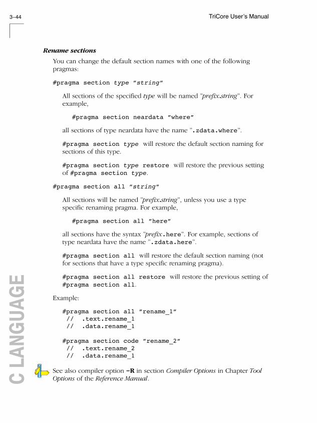
TriCore User’s Manual3−44C LA
NGUA
GE
Rename sections
You can change the default section names with one of the followingpragmas:
#pragma section type "string"
All sections of the specified type will be named "prefix.string". Forexample,
#pragma section neardata "where"
all sections of type neardata have the name ".zdata.where".
#pragma section type will restore the default section naming forsections of this type.
#pragma section type restore will restore the previous settingof #pragma section type.
#pragma section all "string"
All sections will be named "prefix.string", unless you use a typespecific renaming pragma. For example,
#pragma section all "here"
all sections have the syntax "prefix.here". For example, sections oftype neardata have the name ".zdata.here".
#pragma section all will restore the default section naming (notfor sections that have a type specific renaming pragma).
#pragma section all restore will restore the previous setting of#pragma section all.
Example:
#pragma section all "rename_1" // .text.rename_1 // .data.rename_1
#pragma section code "rename_2" // .text.rename_2 // .data.rename_1
See also compiler option −R in section Compiler Options in Chapter ToolOptions of the Reference Manual.

TriCore C Language 3−45
• • • • • • • •
Influence section definition
The following pragmas also influence the section definition:
#pragma section code_init
Code sections are copied from ROM to RAM at program startup.
#pragma section const_init
Sections with constant data are copied from ROM to RAM at programstartup.
#pragma section vector_init
Sections with interrupts and trap vectors are copied from ROM to RAMat program startup.
#pragma section data_overlay
The nearnoclear and farnoclear sections can be overlaid by othersections with the same name. Since default section naming never leadsto sections with the same name, you must force the same name byusing one of the section renaming pragmas. To get noclear sectionsinstead of BSS sections you must also use #pragma noclear.
#pragma section_name_with_module
All section renaming pragmas will use a renaming scheme like"prefix.module_name.pragma_value".
#pragma section_name_with_symbol
All section renaming pragmas will use a renaming scheme like"prefix.symbol_name.pragma_value".
#pragma section_per_data_object
All data objects get their own section, using a naming scheme like"prefix.module_name.symbol_name".
See also compiler option −−section−per−data−object.

TriCore User’s Manual3−46C LA
NGUA
GE
No default section alignment
By default the compiler generates a 4−byte alignment for sections, this isdone because the default initialization code does not know where codeends up and hardware could require a word aligned read/access to thememory. With the compiler option −−no−default−section−alignmentsections are no longer forced to a 4−byte alignment.
Please note that this means that you will have to use your owninitialization code! Furthermore you will have to remove the copy_unit= 4 part of the copytable declaration within the LSL file.

TriCore C Language 3−47
• • • • • • • •
3.11 SWITCH STATEMENT
ctc supports three ways of code generation for a switch statement: a jumpchain (linear switch), a jump table or a lookup table.
A jump chain is comparable with an if/else−if/else−if/else construction. Ajump table is a table filled with target addresses for each possible switchvalue. The switch argument is used as an index within this table. A lookuptable is a table filled with a value to compare the switch argument withand a target address to jump to. A binary search lookup is performed toselect the correct target address.
By default, the compiler will automatically choose the most efficient switchimplementation based on code and data size and execution speed. Youcan influence the selection of the switch method with compiler option −t(−−tradeoff), which determines the speed/size tradeoff.
It is obvious that, especially for large switch statements, the jump tableapproach executes faster than the lookup table approach. Also the jumptable has a predictable behavior in execution speed. No matter the switchargument, every case is reached in the same execution time. However,when the case labels are distributed far apart, the jump table becomessparse, wasting code memory. The compiler will not use the jump tablemethod when the waste becomes excessive.
With a small number of cases, the jump chain method can be faster inexecution and shorter in size.
How to overrule the default switch method
You can overrule the compiler chosen switch method with a pragma:
#pragma switch linear /* force jump chain code */#pragma switch jumptab /* force jump table code */#pragma switch lookup /* force lookup table code */#pragma switch auto /* let the compiler decide the switch method used */#pragma switch restore /* restore previous switch method */
Pragma switch auto is also the default of the compiler.
On the command line you can use compiler option −−switch.

TriCore User’s Manual3−48C LA
NGUA
GE
3.12 LIBRARIES
The compiler ctc comes with standard C libraries (ISO/IEC 9899:1999) andheader files with the appropriate prototypes for the library functions. Thestandard C libraries are available in object format and in C or assemblysource code.
A number of standard operations within C are too complex to generateinline code for. These operations are implemented as run−time libraryfunctions.
The lib directory contains subdirectories with separate libraries for theTriCore 1 and the TriCore 2. Also special MMU libraries are available forderivatives that have a MMU on board. These MMU libraries contain anatural alignment for data objects. For example, word−sized data isword−aligned and double−word−sized data is double−word aligned.Furthermore, protected libraries are available for several functionalproblems.
The protected library sets provide software bypasses for all supported CPUfunctional problems. They must be used in conjunction with theappropriate C compiler workarounds for CPU functional problems. Formore details refer to Chapter 9, CPU Functional Problems in the ReferenceManual.
The directory structure is:
\ctc\lib\ tc1\ TriCore 1 libraries tc2\ TriCore 2 libraries tc1_mmu\ TriCore 1 MMU libraries tc2_mmu\ TriCore 2 MMU libraries p\ tc1* Protected libraries for TC1* problems For example: tc11ib Protected libraries for TC11IB problems tc1766 Protected libraries for TC1766 problems tc1920 Protected libraries for TC1920 problems
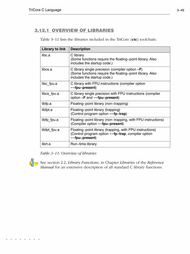
TriCore C Language 3−49
• • • • • • • •
3.12.1 OVERVIEW OF LIBRARIES
Table 3−11 lists the libraries included in the TriCore (ctc) toolchain.
Library to link Description
libc.a C library(Some functions require the floating−point library. Alsoincludes the startup code.)
libcs.a C library single precision (compiler option −F)(Some functions require the floating−point library. Alsoincludes the startup code.)
libc_fpu.a C library with FPU instructions (compiler option−−fpu−present)
libcs_fpu.a C library single precision with FPU instructions (compileroption −F and −−fpu−present)
libfp.a Floating−point library (non−trapping)
libfpt.a Floating−point library (trapping)(Control program option −−fp−trap)
libfp_fpu.a Floating−point library (non−trapping, with FPU instructions)(Compiler option −−fpu−present)
libfpt_fpu.a Floating−point library (trapping, with FPU instructions)(Control program option −−fp−trap, compiler option−−fpu−present)
librt.a Run−time library
Table 3−11: Overview of libraries
See section 2.2, Library Functions, in Chapter Libraries of the ReferenceManual for an extensive description of all standard C library functions.

TriCore User’s Manual3−50C LA
NGUA
GE
3.12.2 PRINTF AND SCANF FORMATTING ROUTINES
The C library functions printf(), fprintf(), vfprintf(),vsprintf(), ... call one single function, _doprint(), that deals with theformat string and arguments. The same applies to all scanf type functions,which call the function _doscan(), and also for the wprintf andwscanf type functions which call _dowprint() and _dowscan()respectively. The C library contains three versions of these routines: int,long and long long versions. If you use floating−point, the formatterfunction for floating−point _doflt() or _dowflt() is called. Dependingon the formatting arguments you use, the correct routine is used from thelibrary. Of course the larger the version of the routine the larger yourproduced code will be.
Note that when you call any of the printf/scanf routines indirect, thearguments are not known and always the long long version withfloating−point support is used from the library.
Example:
#include <stdio.h>
long L;
void main(void){ printf( "This is a long: %ld\n", L );}
The linker extracts the long version without floating−point support fromthe library.
Fixed point format specifiers
The printf and scanf type functions support two additional formatspecifiers for the conversion of fixed−point types (fractional andaccumulator types).

TriCore C Language 3−51
• • • • • • • •
For printf type functions:
%lR An __laccum argument representing a fixed−pointaccumulator number is converted to decimal notation in thestyle [−]ddd.ddd, where the number of digits after thedecimal−point character is equal to the precision specification.
%r A __fract argument representing a fixed−point fractionalnumber is converted to decimal notation in the style [−]d.ddd,where there is one digit (which is non−zero if the argument is−1.0) before the decimal point character and the number ofdigits after it is equal to the precision.
For scanf type functions:
%lR Matches an optionally signed fixed−point accumulator number.The corresponding argument shall be a pointer to __laccum.
%r Matches an optionally signed fixed−point fractional number.The corresponding argument shall be a pointer to __fract.
Example:
#include <stdio.h>
__fract fvalue = 1.0/3;__laccum lacvalue = 1.234;
void main(void){ printf("fvalue is: %r\n", fvalue); printf("lacvalue is: %lR\n", lacvalue);}

TriCore User’s Manual3−52C LA
NGUA
GE
3.12.3 REBUILDING LIBRARIES
If you have manually changed one of the standard C library functions, youneed to recompile the standard C libraries.
’Weak’ symbols are used to extract the most optimal implementation of afunction from the library. For example if your application does not usefloating−point variables the prinf alike functions do not supportfloating−point types either. The compiler emits strong symbols to guidethis process. Do not change the order in which modules are placed in thelibrary since this may break this process.
The sources of the libraries are present in the lib\src directory. Thisdirectory also contains subdirectories with a makefile for each type oflibrary:
lib\src\ p\ tc1*\ libc\makefile libcs\makefile libcs_fpu\makefile tc1\ libc\makefile libcs\makefile libcs_fpu\makefile tc2\ libc\makefile libcs\makefile libcs_fpu\makefile
To rebuild the libraries, follow the steps below.
First make sure that the bin directory for the TriCore toolchain is includedin your PATH environment variable. (See section 1.3.2, Configuring theCommand Line Environment.
1. Make the directory lib\src\tc2\libc the current working directory.
This directory contains a makefile which also uses the default makerules from mktc.mk from the ctc\etc directory.
2. Edit the makefile.

TriCore C Language 3−53
• • • • • • • •
See section 8.3, Make Utility, in Chapter Utilities for an extensivedescription of the make utility and makefiles.
3. Assuming the lib\src\tc2\libc directory is still the current workingdirectory, type:
mktc
to build the library.
The new library is created in the lib\src\tc2\libc directory.
4. Make a backup copy of the original library and copy the new library tothe lib\tc2 directory of the product.

TriCore User’s Manual3−54C LA
NGUA
GE

4
TRICORE ASSEMBLYLANGUAGE
CHAPTER

TriCore User’s Manual4−2AS
SEMBL
Y LA
NGUA
GE
4
CHAPTER

TriCore Assembly Language 4−3
• • • • • • • •
4.1 INTRODUCTION
In this chapter the most important aspects of the TriCore assemblylanguage are described. For a complete overview of the TriCore2architecture, refer to the TriCore2 Architecture Overview Handbook [2002,Infineon].
4.2 ASSEMBLY SYNTAX
An assembly program consists of zero or more statements. A statementmay optionally be followed by a comment. Any source statement can beextended to more lines by including the line continuation character (\) asthe last character on the line. The length of a source statement (first lineand continuation lines) is only limited by the amount of available memory.
Mnemonics and directives are case insensitive. Labels, symbols, directivearguments, and literal strings are case sensitive.
The syntax of an assembly statement is:
[label[:]] [instruction | directive | macro_call] [;comment]
label A label is a special symbol which is assigned the value andtype of the current program location counter. A label canconsist of letters, digits and underscore characters (_). Thefirst character cannot be a digit. A label which is prefixed bywhitespace (spaces or tabs) has to be followed by a colon (:).The size of an identifier is only limited by the amount ofavailable memory. Note that if you use a reserved symbol asa label it has to be followed by a colon.
Examples:
LAB1: ; This label is followed by a colon and can start with a space or tabLAB1 ; This label has to start at the beginning of a line

TriCore User’s Manual4−4AS
SEMBL
Y LA
NGUA
GE
instruction An instruction consists of a mnemonic and zero, one or moreoperands. It must not start in the first column. Operands aredescribed in section 4.4, Operands of an AssemblyInstruction. The instructions are described in the TriCoreArchitecture Manuals.
Examples:
ret ; No operand call label ; One operand mov D0,#1 ; Two operands jne D0,#0,loop ; Three operands madd D2,D3,D0,D1 ; Four operands insert D1,D2,#3,#16,#2 ; Five operands
directive With directives you can control the assembler from within theassembly source. These must not start in the first column.Directives are described in section 4.8, Assembler Directivesand Controls.
macro_call A call to a previously defined macro. It must not start in thefirst column. Macros are described in section 4.10 MacroOperations.
You can use empty lines or lines with only comments.
Apart from the assembly statements as described above, you can put aso−called ’control line’ in your assembly source file. These lines start witha $ in the first column and alter the default behavior of the assembler.
$control
For more information on controls see section 4.8, Assembler Directives andControls.
4.3 ASSEMBLER SIGNIFICANT CHARACTERS
You can use all ASCII characters in the assembly source both in strings andin comments. Also the extended characters from the ISO 8859−1 (Latin−1)set are allowed.
Some characters have a special meaning to the assembler. Specialcharacters associated with expression evaluation are described in section4.6.3, Expression Operators. Other special assembler characters are:

TriCore Assembly Language 4−5
• • • • • • • •
Character Description
; Start of a comment
\ Line continuation character or
Macro operator: argument concatenation
? Macro operator: return decimal value of a symbol
% Macro operator: return hex value of a symbol
^ Macro operator: override local label
" Macro string delimiter or
Quoted string .DEFINE expansion character
’ String constants delimiter
@ Start of a built−in assembly function
* Location counter substitution
# Constant number
++ String concatenation operator
[ ] Substring delimiter
4.4 OPERANDS
In an instruction, the mnemonic is followed by zero, one or moreoperands. An operand has one of the following types:
Operand Description
symbol A symbolic name as described in section 4.5, SymbolNames. Symbols can also occur in expressions.
register Any valid register or a register pair, register quad, registerextension, register part or special function register.
expression Any valid expression as described in the section 4.6,Assembly Expressions.
address A combination of expression, register and symbol.
4.4.1 OPERANDS AND ADDRESSING MODES
The TriCore assembly language has several addressing modes. These arelisted below with a short description. For details see the TriCore 1 UnifiedProcessor Core v1.3 Architecture Manual, Doc v1.3.3 [2002−09, Infineon]

TriCore User’s Manual4−6AS
SEMBL
Y LA
NGUA
GE
Absolute addressing
The instruction uses an 18−bit constant as the memory address. The full32−bit address results from moving the most significant 4 bits of the 18−bitconstant to the most significant bits of the 32−bit address. The other bitsare zero filled.
Syntax:
constant18
Base+offset
The effective address is the sum of an address register and thesign−extended 10−bit or 16−bit offset.
Syntax:
[An]offset10[An]offset16
Pre−increment/decrement
This addressing mode uses the sum of the address register and the offsetboth as the effective address and as the value written back into theaddress register. Use the minus sign for a pre−decrement.
Syntax:
[+An]offset10
Post−increment/decrement
This addressing mode uses the value of the address register as theeffective address, and then updates this register by adding thesign−extended 10−bit offset to its previous value. Use the minus sign for apost−decrement.
Syntax:
[An+]offset10

TriCore Assembly Language 4−7
• • • • • • • •
Circular addressing
This addressing mode is used for accessing data values in circular buffers.It uses an address register pair to hold the state it requires. The evenregister is always a base address (B). The most−significant half of the oddregister is the buffer size (L). The least significant half holds the index intothe buffer (I). The effective address is (B+I). The buffer occupies memoryfrom addresses B to B+L−1. The 10−bit offset is specified in the instructionword and is a byte−offset that can be either positive or negative.
Syntax:
[An+c]offset10
Bit−reverse addressing
Bit reverse addressing is used to access arrays used in FFT algorithms.Bit−reverse addressing uses an address register pair to hold the requiredstate. The even register is the base address of the array (B), theleast−significant half of the odd register is the index into the array (I), andthe most−significant half is the modifier (M) which is added to I after everyaccess. The effective address is B+reverse(I). The reverse() functionexchanges bit n with bit (15−n) for n = 0, ..., 7. The index, I, ispost−incremented and its new value is (I + M), where M is the mostsignificant half of the odd register.
Syntax:
[An+r]
Indexed addressing
The indexed addressing mode uses an address register pair to hold therequired state. The Aeven register is the base address of the array (B). TheAodd register is divided equally between the index into the array (I), andthe modifier (N) which is added to I after every access.
Aodd
Aeven
N I
B
All load (LD.xxx) instructions, all store(ST.xxx except ST.T) instructions,the load/modify/store (SWAP.W,LDMST) instructions and the cachemanagement (CACHEA.xxx) instructions are able to use the indexedaddressing mode.
Syntax:

TriCore User’s Manual4−8AS
SEMBL
Y LA
NGUA
GE
[Aa/Ab+i]
ld.w d0,[a0/a1+i] ; load word indexed addressing modest.w [a2/a3+i],d0 ; store word indexed addressing mode
4.4.2 PCP ADDRESSING MODES
The PCP assembly language has several addressing modes. Theseaddressing modes are used for FPI addressing, PRAM data indirectaddressing or flow control destination addressing. For details see thePCP/DMA Architecture manual from Siemens.
4.5 SYMBOL NAMES
User−defined symbols
A user−defined symbol can consist of letters, digits and underscorecharacters (_). The first character cannot be a digit. The size of anidentifier is only limited by the amount of available memory. The case ofthese characters is significant. You can define a symbol by means of alabel declaration or an equate or set directive.
Labels
Symbols used for memory locations are referred to as labels. It is allowedto use reserved symbols as labels as long as the label is followed by acolon.
Reserved symbols
Register names and names of assembler directives and controls arereserved for the system, so you cannot use these for user−defined symbols.The case of these built−in symbols is insignificant. Symbol names andother identifiers beginning with a period (.) are also reserved for thesystem.

TriCore Assembly Language 4−9
• • • • • • • •
The following symbols are predefined:
Symbol Description
__ASTC__ Contains the name of the assembler ("astc")
__ASPCP__ Contains the name of the PCP assembler ("aspcp")
__FPU__ Defined when you use assembler option−−fpu−present (allow use of FPU instructions)
__MMU__ Defined when you use assembler option−−mmu−present (allow use of MMU instructions)
__TC2__ Defined when you use assembler option−−is−tricore2 (allow use of TriCore 2 instructions)
Table 4−1: Predefined symbols
Examples
Valid symbol names Invalid symbol names
loop_1ENTRYa_B_c_aBC
1_loop (starts with a number)d15 (reserved register name).space (reserved directive name)
4.6 ASSEMBLY EXPRESSIONS
An expression is a combination of symbols, constants, operators, andparentheses which represent a value that is used as an operand of anassembler instruction (or directive).
Expressions can contain user−defined labels (and their associated integeror floating−point values), and any combination of integers, floating−pointnumbers, or ASCII literal strings.
Expressions follow the conventional rules of algebra and booleanarithmetic.
Expressions that can be evaluated at assembly time are called absoluteexpressions. Expressions where the result is unknown until all sectionshave been combined and located, are called relocatable or relativeexpressions.

TriCore User’s Manual4−10AS
SEMBL
Y LA
NGUA
GE
When any operand of an expression is relocatable, the entire expression isrelocatable. Relocatable expressions are emitted in the object file and areevaluated by the linker. Relocatable expressions can only contain integralfunctions; floating−point functions and numbers are not supported by theELF/DWARF object format.
The assembler evaluates expressions with 64−bit precision in two’scomplement.
The syntax of an expression can be any of the following:
− numeric contant
− string
− symbol
− expression binary_operator expression
− unary_operator expression
− ( expression )
− function call
All types of expressions are explained in separate sections.
4.6.1 NUMERIC CONSTANTS
Numeric constants can be used in expressions. If there is no prefix, theassembler assumes the number is a decimal number.
Base Description Example
Binary ’0B’ or ’0b’ followed by binary digits (0,1). 0B11010b11001010
Hexadecimal ’0X’ or ’0x’ followed by a hexadecimaldigits (0−9, A−F, a−f).
0X12FF0x450x9abc
Decimal,integer Decimal digits (0−9).
121245
Decimal,floating−point
Includes a decimal point, or an ’E’ or ’e’followed by the exponent.
6E10.63.142.7e10

TriCore Assembly Language 4−11
• • • • • • • •
4.6.2 STRINGS
ASCII characters, enclosed in single (’) or double (″) quotes constitue anASCII string. Strings between double quotes allow symbol substitution by a.DEFINE directive, whereas strings between single quotes are alwaysliteral strings. Both types of strings can contain escape characters.
Strings constants in expressions are evaluated to a number (each characteris replaced by its ASCII value). Strings in expressions can have the size ofa long word (first 4 characters) or less depending on the operand of aninstruction or directive; any subsequent characters in the string areignored. In this case the assembler issues a warning. An exception to thisrule is when a string longer than 4 characters is used in a .BYTE assemblerdirective; in that case all characters result in a constant byte. Null stringshave a value of 0.
Square brackets ([ ]) delimit a substring operation in the form:
[string,offset,length]
offset is the start position within string. length is the length of the desiredsubstring. Both values may not exceed the size of string.
Examples
’ABCD’ ; (0x41424344)
’’’79’ ; to enclose a quote double it
"A\"BC" ; or to enclose a quote escape it
’AB’+1 ; (0x00004143) string used in expression
’’ ; null string
.word ’abcdef’ ; (0x64636261) ’ef’ are ignored ; warning: string value truncated
’abc’++’de’ ; you can concatenate ; two strings with the ’++’ operator. ; This results in ’abcde’
[’TriCore’,0,3] ; results in the substring ’Tri’

TriCore User’s Manual4−12AS
SEMBL
Y LA
NGUA
GE
4.6.3 EXPRESSION OPERATORS
The next table shows the assembler operators. They are ordered accordingto their precedence. Operators of the same precedence are evaluated leftto right. Expressions between parentheses have the highest priority(innermost first).
Valid operands include numeric constants, literal ASCII strings andsymbols.
Most assembler operators can be used with both integer and floating−pointvalues. If one operand has an integer value and the other operand has afloating−point value, the integer is converted to a floating−point valuebefore the operator is applied. The result is a floating−point value.
Type Operator
Name Description
( ) parentheses Expressions enclosed byparenthesis are evaluated first.
Unary + plus Returns the value of its operand.
− minus Returns the negative of its operand.
~ complement Returns complement, integer only
! logical negate Returns 1 if the operands’ value is0; otherwise 0. For example, if bufis 0 then !buf is 1.
Arithmetic * multiplication Yields the product of two operands.
/ division Yields the quotient of the division ofthe first operand by the second.With integers, the divide operationproduces a truncated integer.
% modulo Integer only: yields the remainderfrom a division of the first operandby the second.
+ addtion Yields the sum of its operands.
− subtraction Yields the difference of itsoperands.

TriCore Assembly Language 4−13
• • • • • • • •
DescriptionNameOperator
Type
Shift << shift left Integer only: shifts the left operandto the left (zero−filled) by thenumber of bits specified by the rightoperand.
>> shift right Integer only: shifts the left operandto the right (sign bit extended) bythe number of bits specified by theright operand.
Relational <
<=
>
>=
==
!=
less than
less or equal
greater than
greater or equal
equal
not equal
If the indicated condition is:
− True: result is an integer 1
− False: result is an integer 0
Be cautious when you usefloating−point values in an equalitytest; rounding errors can causeunexpected results.
Bitwise & AND Integer only: yields bitwise AND
| OR Integer only: yields bitwise OR
^ exclusive OR Integer only: yields bitwiseexclusive OR
Logical && logical AND Returns an integer 1 if bothoperands are nonzero; otherwise, itreturns an integer 0.
|| logical OR Returns an integer 1 if either of theoperands is nonzero; otherwise, itreturns an integer 1
Table 4−2: Assembly expression operators

TriCore User’s Manual4−14AS
SEMBL
Y LA
NGUA
GE
4.7 BUILT−IN ASSEMBLY FUNCTIONS
The assembler has several built−in functions to support data conversion,string comparison, and math computations. You can use functions as termsin any expression. Functions have the following syntax:
Syntax of an assembly function
@function_name([argument[,argument]...])
Functions start with the ’@’ character and have zero or more arguments,and are always followed by opening and closing parentheses. White space(a blank or tab) is not allowed between the function name and theopening parenthesis and between the (comma−separated) arguments.
The built−in assembler functions are grouped into the following types:
• Mathematical functions comprise, among others, transcendental,random value, and min/max functions.
• Conversion functions provide conversion between integer,floating−point, and fixed point fractional values.
• String functions compare strings, return the length of a string, andreturn the position of a substring within a string.
• Macro functions return information about macros.
• Address calculation functions return the high or low part of anaddress.
• Assembler mode functions relating assembler operation.
The following tables provide an overview of all built−in assemblerfunctions. For a detailed description of these functions, see section 3.2,Built−in Assembly Function, in Chapter Assembly Language of theReference Manual.

TriCore Assembly Language 4−15
• • • • • • • •
Overview of mathematical functions
Function Description
@ABS(expr) Absolute value
@ACS(expr) Arc cosine
@ASN(expr) Arc sine
@AT2(expr1,expr2) Arc tangent
@ATN(expr) Arc tangent
@CEL(expr) Ceiling function
@COH(expr) Hyperbolic cosine
@COS(expr) Cosine
@FLR(expr) Floor function
@L10(expr) Log base 10
@LOG(expr) Natural logarithm
@MAX(expr,[,...,exprN]) Maximum value
@MIN(expr,[,...,exprN]) Minimum value
@POW(expr1,expr2) Raise to a power
@RND() Random value
@SGN(expr) Returns the sign of an expression as −1, 0 or 1
@SIN(expr) Sine
@SNH(expr) Hyperbolic sine
@SQT(expr) Square root
@TAN(expr) Tangent
@TNH(expr) Hyperbolic tangent
@XPN(expr) Exponential function (raise e to a power)

TriCore User’s Manual4−16AS
SEMBL
Y LA
NGUA
GE
Overview of conversion functions
Function Description
@CVF(expr) Convert integer to floating−point
@CVI(expr) Convert floating−point to integer
@FLD(base,value, width[,start])
Shift and mask operation
@FRACT(expr) Convert floating−point to 32−bit fractional
@SFRACT(expr) Convert floating−point to 16−bit fractional
@LNG(expr) Concatenate to double word
@LUN(expr) Convert long fractional to floating−point
@RVB(expr1[,expr2]) Reverse order of bits in field
@UNF(expr) Convert fractional to floating−point
Overview of string functions
Function Description
@CAT(str1,str2) Concatenate strings
@LEN(string) Length of string
@POS(str1,str2[,start]) Position of substring in string
@SCP(str1,str2) Returns 1 if two strings are equal
@SUB(string,expr,expr) Returns substring in string
Overview of macro functions
Function Description
@ARG(’symbol’|expr) Test if macro argument is present
@CNT() Return number of macro arguments
@MAC(symbol) Test if macro is defined
@MXP() Test if macro expansion is active

TriCore Assembly Language 4−17
• • • • • • • •
Overview of address calculation functions
Function Description
@DPTR(expr) PCP only: returns bits 6−13 of the pcpdataaddress
@HI(expr) Returns upper 16 bits of expression value
@HIS(expr) Returns upper 16 bits of expression value,adjusted for signed addition
@INIT_R7(start,dptr,flags) PCP only: returns the 32−bit value to initializeR7
@LO(expr) Returns lower 16 bits of expression value
@LOS(expr) Returns lower 16 bits of expression value,adjusted for signed addition
@LSB(expr) Get least significant byte of a word
@MSB(expr) Get most significant byte of a word
Overview of assembler mode functions
Function Description
@ASPCP() Returns the name of the PCP assemblerexecutable
@ASTC() Returns the name of the assembler executable
@CPU(string) Test if CPU type is selected
@DEF(’symbol’|symbol) Returns 1 if symbol has been defined
@EXP(expr) Expression check
@INT(expr) Integer check
@LST() LIST control flag value

TriCore User’s Manual4−18AS
SEMBL
Y LA
NGUA
GE
4.8 ASSEMBLER DIRECTIVES AND CONTROLS
An assembler directive is simply a message to the assembler. Assemblerdirectives are not translated into machine instructions. There are threemain groups of assembler directives.
• Assembler directives that tell the assembler how to go about translatinginstructions into machine code. This is the most typical form ofassembly directives. Typically they tell the assembler where to put aprogram in memory, what space to allocate for variables, and allowyou to initialize memory with data. When the assembly source isassembled, a location counter in the assembler keeps track of wherethe code and data is to go in memory.
The following directives fall under this group:
− Assembly control directives
− Symbol definition directives
− Data definition / Storage allocation directives
− Debug directives
• Directives that are interpreted by the macro preprocessor. Thesedirectives tell the macro preprocessor how to manipulate yourassembly code before it is actually being assembled. You can use thesedirectives to write macros and to write conditional source code. Parts ofthe code that do not match the condition, will not be assembled at all.
• Some directives act as assembler options and most of them indeed dohave an equivalent assembler (command line) option. The advantageof using a directive is that with such a directive you can overrule theassembler option for a particular part of the code. Directives of thiskind are called controls. A typical example is to tell the assembler withan option to generate a list file while with the controls $LIST ON and$LIST OFF you overrule this option for a part of the code that you donot want to appear in the list file. Controls always appear on a separateline and start with a ’$’ sign in the first column.
The following controls are available:
− Assembly listing controls
− Miscellaneous controls
Each assembler directive or control has its own syntax. You can useassembler directives and controls in the assembly code as pseudoinstructions.

TriCore Assembly Language 4−19
• • • • • • • •
4.8.1 OVERVIEW OF ASSEMBLER DIRECTIVES
The following tables provide an overview of all assembler directives. For adetailed description, see section 3.3.2, Detailed Description of AssemblerDirectives, in Chapter Assembly Language of the Reference Manual.
Overview of assembly control directives
Directive Description
.COMMENT Start comment lines. You cannot use this directive in.IF/.ELSE/.ENDIF constructs and .MACRO/.DUPdefinitions.
.DEFINE Define substitution string
.END End of source program
.FAIL Programmer generated error message
.INCLUDE Include file
.MESSAGE Programmer generated message
.ORG Initialize memory space and location counters tocreate a nameless section
.SDECL Declare a section with name, type and attributes
.SECT Activate a declared section
.UNDEF Undefine .DEFINE symbol
.WARNING Programmer generated warning
Overview of symbol definition directives
Function Description
.EQU Assigns permanent value to a symbol
.EXTERN External symbol declaration
.GLOBAL Global symbol declaration
.LOCAL Local symbol declaration
.SET Set temporary value to a symbol
.SIZE Set size of symbol in the ELF symbol table
.TYPE Set symbol type in the ELF symbol table
.WEAK Mark symbol as ’weak’

TriCore User’s Manual4−20AS
SEMBL
Y LA
NGUA
GE
Overview of data definition / storage allocation directives
Function Description
.ACCUM Define 64−bit constant in 18 + 46 bits format
.ALIGN Define alignment
.ASCII / .ASCIIZ Define ASCII string without / with ending NULL byte
.BYTE Define constant byte (not for PCP)
.FLOAT / .DOUBLE Define a 32−bit / 64−bit floating−point constant
.FRACT / .SFRACT Define a 16−bit / 32−bit constant fraction
.SPACE Define storage
.WORD / .HALF Define a word / half−word constant (not for PCP)
Overview of macro and conditional assembly directives
Function Description
.DUP Duplicate sequence of source lines
.DUPA Duplicate sequence with arguments
.DUPC Duplicate sequence with characters
.DUPF Duplicate sequence in loop
.ENDM End of macro or duplicate sequence
.EXITM Exit macro
.IF/.ELIF/.ELSE/.ENDIF Conditional assembly
.MACRO Define macro
.PMACRO Undefine (purge) macro
Overview of debug directives
Function Description
.CALLS Passes call information to object file. Used by thelinker to build a call graph.

TriCore Assembly Language 4−21
• • • • • • • •
4.8.2 OVERVIEW OF ASSEMBLER CONTROLS
The following tables provide an overview of all assembler controls. For adetailed description, see section 3.3.4, Detailed Description of AssemblerControls, in Chapter Assembly Language of the Reference Manual.
Overview of assembler listing controls
Function Description
$LIST ON/OFF Generation of assembly list file temporaryON/OFF
$LIST "flags" Exclude / include lines in assembly list file
$PAGE Generate formfeed in assembly list file
$PAGE settings Define page layout for assemly list file
$PRCTL Send control string to printer
$STITLE Set program subtitle in header of assembly listfile
$TITLE Set program title in headerof assembly list file
Overview of miscellaneous assembler controls
Function Description
$defect_TCnum ON/OFF Enable/disable assembler check for specifiedfunctional problem, defect is one of CPU, DMU,PMI or PMU
$DEBUG ON/OFF Generation of symbolic debug ON/OFF
$DEBUG "flags" Generation of symbolic debug ON/OFF
$FPU Allow single precision floating−point instructions
$HW_ONLY Prevent substitution of assembly instructions bysmaller or faster instructions
$IDENT LOCAL/GLOBAL Assembler treats labels by default as local orglobal
$MMU Allow memory management instructions
$OBJECT Alternative name for the generated object file
$TC2 Allow TriCore 2 instructions
$WARNING OFF [num] Suppress all or some warnings
TriCore User’s Manual4−22AS
SEMBL
Y LA
NGUA
GE
4.9 WORKING WITH SECTIONS
Sections are absolute or relocatable blocks of contiguous memory that cancontain code or data. Some sections contain code or data that yourprogram declared and uses directly, while other sections are created bythe compiler or linker and contain debug information or code or data toinitialize your application. These sections can be named in such a way thatdifferent modules can implement different parts of these sections. Thesesections are located in memory by the linker (using the linker scriptlanguage, LSL) so that concerns about memory placement are postponeduntil after the assembly process.
All instructions and directives which generate data or code must be withinan active section. The assembler emits a warning if code or data startswithout a section definition and activation. The compiler automaticallygenerates sections. If you program in assembly you have to define sectionsyourself.
For more information about locating sections see section 7.7.7 The SectionLayout Definition: Locating Sections in chapter Using the Linker.
Section definition
Sections are defined with the .SDECL directive and have a name. A sectionmay have attributes to instruct the linker to place it on a predefinedstarting address, or that it may be overlaid with another section.
.SDECL "name", type [, attribute ]... [AT address]
See the .SDECL directive in section 3.3.2, Detailed Description of AssemblerDirectives, in chapter Assembly Language of the Reference Manual, for acomplete description of all possible attributes.
Section activation
Sections are defined once and are activated with the .SECT directive.
.SECT "name"

TriCore Assembly Language 4−23
• • • • • • • •
The linker will check between different modules and emits an errormessage if the section attributes do not match. The linker will alsoconcatenate all matching section definitions into one section. So, all "code"sections generated by the compiler will be linked into one big "code"chunk which will be located in one piece. By using this naming scheme itis possible to collect all pieces of code or data belonging together into onebigger section during the linking phase. A .SECT directive referring to anearlier defined section is called a continuation. Only the name can bespecified.
Example 1
.SDECL ".text.hello.main",CODE
.SECT ".text.hello.main"
Defines and activates a relocatable section in CODE memory. Other partsof this section, with the same name, may be defined in the same moduleor any other module. Other modules should use the same .SDECLstatement. When necessary, it is possible to give the section an absolutestarting address with the locator description file.
Example 2
.SDECL ".CONST", CODE AT 0x1000
.SECT ".CONST"
Defines and activates an absolute section named .CONST starting onaddress 0x1000.
Example 3
.SDECL ".fardata", DATA, CLEAR
.SECT ".fardata"
Defines a relocatable named section in DATA memory. The CLEARattribute instructs the linker to clear the memory located to this section.When this section is used in another module it must be defined identically.Continuations of this section in the same module are as follows:
.SECT ".fardata"

TriCore User’s Manual4−24AS
SEMBL
Y LA
NGUA
GE
4.10 MACRO OPERATIONS
Macros provide a shorthand method for inserting a repeated pattern ofcode or group of instructions. Yuo can define the pattern as a macro, andthen call the macro at the points in the program where the pattern wouldrepeat.
Some patterns contain variable entries which change for each repetition ofthe pattern. Others are subject to conditional assembly.
When a macro is called, the assembler executes the macro and replacesthe call by the resulting in−line source statements. ’In−line’ means that allreplacements act as if they are one the same line as the macro call. Thegenerated statements may contain substitutable arguments. The statementsproduced by a macro can be any processor instruction, almost anyassembler directive, or any previously−defined macro. Source statementsresulting from a macro call are subject to the same conditions andrestrictions as any other statements.
Macros can be nested. The assembler processes nested macros when theouter macro is expanded.
4.10.1 DEFINING A MACRO
The first step in using a macro is to define it in the source file. Thedefinition of a macro consists of three parts:
• Header, which assigns a name to the macro and defines the arguments.
• Body, which contains the code or instructions to be inserted when temacro is called.
• Terminator, which indicates the end of the macro definition (.ENDMdirective).
A macro definition takes the following form:
Header: macro_name .MACRO [arg[,arg...] [; comment] .Body: source statements .Terminator: .ENDM
If the macro name is the same as an existing assembler directive ormnemonic opcode, the assembler replaces the directive or mnemonicopcode with the macro and issues a warning.

TriCore Assembly Language 4−25
• • • • • • • •
The arguments are symbolic names that the macro preprocessor replaceswith the literal arguments when the macro is expanded (called). Eachargument must follow the same rules as global symbol names. Argumentnames cannot start with a percent sign (%).
Example
The macro definition:
CONSTD .MACRO reg,value ;header mov.u reg,#@lo(value) ;body addih reg,reg,#@hi(value) .ENDM ;terminator
The macro call:
.SDECL "data",DATA .SECT "data"
CONSTD d4,0x12345678
.END
The macro expands as follows:
mov.u d4,#@lo(0x12345678) addih d4,d4,#@hi(0x12345678)
4.10.2 CALLING A MACRO
To invoke a macro, construct a source statement with the following format:
[label] macro_name [arg[,arg...]] [; comment]
where:
label An optional label that corresponds to the value of thelocation counter at the start of the macro expansion.
macro_name The name of the macro. This must be in the operationfield.
arg One or more optional, substitutable arguments. Multiplearguments must be separated by commas.
comment An optional comment.

TriCore User’s Manual4−26AS
SEMBL
Y LA
NGUA
GE
The following applies to macro arguments:
• Each argument must correspond one−to−one with the formal argumentsof the macro definition. If the macro call does not contain the samenumber of arguments as the macro definition, the assembler issues awarning.
• If an argument has an embedded comma or space, you must surroundthe argument by single quotes (’).
• You can declare a macro call argument as NULL in three ways:
− enter delimiting commas in succession with no intervening spaces
macroname ARG1,,ARG3 ; the second argument ; is a NULL argument
− terminate the argument list with a comma, the arguments thatnormally would follow, are now considered NULL
macroname ARG1, ; the second and all following ; arguments are NULL
− declare the argument as a NULL string
• No character is substituted in the generated statements that reference aNULL argument.

TriCore Assembly Language 4−27
• • • • • • • •
4.10.3 USING OPERATORS FOR MACRO ARGUMENTS
The assembler recognizes certain text operators within macro definitionswhich allow text substitution of arguments during macro expansion. Youcan use these operators for text concatenation, numeric conversion, andstring handling.
Operator Name Description
\ Macro argumentconcatenation
Concatenates a macro argument withadjacent alphanumeric characters.
? Return decimalvalue of symbol
Substitutes the ?symbol sequence with acharacter string that represents the decimalvalue of the symbol.
% Return hexvalue of symbol
Substitutes the %symbol sequence with acharacter string that represents thehexadecimal value of the symbol.
" Macro stringdelimiter
Allows the use of macro arguments as literalstrings.
^ Macro local labeloverride
Causes local labels in its term to be evaluatedat normal scope rather than at macro scope.
Argument Concatenation Operator − \
Consider the following macro definition:
SWAP_MEM .MACRO REG1,REG2 ;swap memory contents LD.W D0,[A\REG1] ;use D0 as temp LD.W D1,[A\REG2] ;use D1 as temp ST.W [A\REG1],D1 ST.W [A\REG2],D0 .ENDM
The macro is called as follows:
SWAP_MEM 0,1
The macro expands as follows:
LD.W D0,[A0] LD.W D1,[A1] ST.W [A0],D1 ST.W [A1],D0
TriCore User’s Manual4−28AS
SEMBL
Y LA
NGUA
GE
The macro preprocessor substitutes the character ’0’ for the argumentREG1, and the character ’1’ for the argument REG2. The concatenationoperator (\) indicates to the macro preprocessor that the substitutioncharacters for the arguments are to be concatenated with the character ’A’.
Without the ’\’ operator the macro would expand as:
LD.W D0,[AREG1] LD.W D1,[AREG2] ST.W [AREG1],D1 ST.W [AREG2],D0
which results in an assembler error.
Decimal value Operator − ?
Instead of substituting the formal arguments with the actual macro callarguments, you can also use the value of the macro call arguments.
Consider the following source code that calls the macro SWAP_SYM afterthe argument AREG has been set to 0 and BREG has been set to 1.
AREG .SET 0BREG .SET 1 SWAP_SYM AREG,BREG
If you want to replace the arguments with the value of AREG and BREGrather than with the literal strings ’AREG’ and ’BREG’, you can use the ?operator and modify the macro as follows:
SWAP_SYM .MACRO REG1,REG2 ;swap memory contents LD.W D0,_lab\?REG1 ;use D0 as temp LD.W D1,_lab\?REG2 ;use D1 as temp ST.W _lab\?REG1,D1 ST.W _lab\?REG2,D0 .ENDM
The macro first expands as follows:
LD.W D0,_lab\?AREG LD.W D1,_lab\?BREG ST.W _lab\?AREG,D1 ST.W _lab\?BREG,D0

TriCore Assembly Language 4−29
• • • • • • • •
Then ?AREG is replaced by ’0’ and ?BREG is replaced by ’1’:
LD.W D0,_lab\1 LD.W D1,_lab\2 ST.W _lab\1,D1 ST.W _lab\2,D0
Because of the concatenation operator ’\’ the strings are concatenated:
LD.W D0,_lab1 LD.W D1,_lab2 ST.W _lab1,D1 ST.W _lab2,D0
Hex Value Operator − %
The percent sign (%) is similar to the standard decimal value operator (?)except that it returns the hexadecimal value of a symbol.
Consider the following macro definition:
GEN_LAB .MACRO LAB,VAL,STMTLAB\%VAL STMT .ENDM
A symbol with the name NUM is set to 10 and the macro is called withNUM as argument:
NUM .SET 10 GEN_LAB HEX,NUM,NOP
The macro expands as follows:
HEXA NOP
The %VAL argument is replaced by the character ’A’ which represents thehexadecimal value 10 of the argument VAL.
Argument String Operator − "
To generate a literal string, enclosed by single quotes (’), you must use theargument string operator (") in the macro definition.
Consider the following macro definition:
STR_MAC .MACRO STRING .BYTE "STRING" .ENDM

TriCore User’s Manual4−30AS
SEMBL
Y LA
NGUA
GE
The macro is called as follows:
STR_MAC ABCD
The macro expands as follows:
.BYTE ’ABCD’
Within double quotes .DEFINE directive definitions can be expanded.Take care when using constructions with quotes and double quotes toavoid inappropriate expansions. Since a .DEFINE expansion occurs beforea macro substitution, all DEFINE symbols are replaced first within a macroargument string:
.DEFINE LONG ’short’STR_MAC .MACRO STRING .MESSAGE ’This is a LONG STRING’ .MESSAGE "This is a LONG STRING" .ENDM
If the macro is called as follows:
STR_MAC sentence
The macro expands as:
.MESSAGE ’This is a LONG STRING’
.MESSAGE ’This is a short sentence’
Single quotes prevent expansion so the first .MESSAGE is not stated as is.In the double quoted .MESSAGE, first the define LONG is expanded to’short’ and then the argument STRING is substituted by ’sentence’.
Macro Local Label Override Operator − ^
If you use labels in macros, the assembler normally generates anotherunique name for the labels (such as LAB__M_L0000001).
The macro ^−operator prevents name mangling on macro local labels.
Consider the following macro definition:
INIT .MACRO ARG, CNT LD.W D0,1^LAB: .BYTE ARG JNEI D0,#CNT,^LAB .ENDM

TriCore Assembly Language 4−31
• • • • • • • •
The macro is called as follows:
INIT 2,4
The macro expands as:
LD.W D0,1LAB: .BYTE 2 JNEI D0,#4,LAB
Without the ^ operator, the macro preprocessor would choose anothername for LAB because the label already exists. The macro then wouldexpand like:
LD.W D0,1LAB__M_L000001: .BYTE 2 JNEI D0,#4,LAB__M_L000001
4.10.4 USING THE .DUP, .DUPA, .DUPC, .DUPFDIRECTIVES AS MACROS
The .DUP, .DUPA, .DUPC, and .DUPF directives are specialized macroforms to repeat a block of source statements. You can think of them as asimultaneous definition and call of an unnamed macro. The sourcestatements between the .DUP, .DUPA, .DUPC, and .DUPF directives andthe .ENDM directive follow the same rules as macro definitions.
For a detailed description of these directives, see section 3.3, AssemblerDirectives, in Chapter Assembly Language of the Reference Manual.
4.10.5 CONDITIONAL ASSEMBLY: .IF, .ELIF AND .ELSEDIRECTIVES
With the conditional assembly directives you can instruct the macropreprocessor to use a part of the code that matches a certain condition.
You can specify assembly conditions with arguments in the case ofmacros, or through definition of symbols via the .DEFINE, .SET, and.EQU directives.

TriCore User’s Manual4−32AS
SEMBL
Y LA
NGUA
GE
The built−in functions of the assembler provide a versatile means of testingmany conditions of the assembly environment.
You can use conditional directives also within a macro definition to checkat expansion time if arguments fall within a certain range of values. In thisway macros become self−checking and can generate error messages to anydesired level of detail.
The conditional assembly directive .IF has the following form:
.IF expression . .[.ELIF expression] ;(the .ELIF directive is optional) . .[.ELSE] ;(the .ELSE directive is optional) . ..ENDIF
The expression must evaluate to an absolute integer and cannot containforward references. If expression evaluates to zero, the .IF−condition isconsidered FALSE. Any non−zero result of expression is considered asTRUE.
For a detailed description of these directives, see section 3.3, AssemblerDirectives, in Chapter Assembly Language of the Reference Manual.

5
USING THECOMPILER
CHAPTER

TriCore User’s Manual5−2CO
MPILE
R
5
CHAPTER

Using the Compiler 5−3
• • • • • • • •
5.1 INTRODUCTION
EDE uses a makefile to build your entire project, from C source till thefinal ELF/DWARF object file which serves as input for the debugger.
Although in EDE you cannot run the compiler separately from the othertools, this chapter discusses the options that you can specify for thecompiler.
On the command line it is possible to call the compiler separately from theother tools. However, it is recommended to use the control program cctcfor command line invocations of the toolchain (see section 8.2, ControlProgram, in Chapter Using the Utilities). With the control program it ispossible to call the entire toolchain with only one command line.
The compiler takes the following files for input and output:
assembly file
C source file
C compiler
.ic
ctc.err
.src
C source file(hand coded)
.c
error messages
Figure 5−1: C compiler
This chapter first describes the compilation process which consists of afrontend and a backend part. During compilation the code is optimized inseveral ways. The various optimizations are described in the secondsection. Third it is described how to call the compiler and how to use itsoptions. An extensive list of all options and their descriptions is includedin the section 5.1, Compiler Options, in Chapter 5, Tool Options, of theReference Manual. Finally, a few important basic tasks are described.

TriCore User’s Manual5−4CO
MPILE
R5.2 COMPILATION PROCESS
During the compilation of a C program, the compiler ctc runs through anumber of phases that are divided into two groups: frontend and backend.
The backend part is not called for each C statement, but starts after acomplete C module or set of modules has been processed by the frontend(in memory). This allows better optimization.
The compiler requires only one pass over the input file which results inrelative fast compilation.
Frontend phases
1. The preprocessor phase:
The preprocessor includes files and substitutes macros by C source. It usesonly string manipulations on the C source. The syntax for the preprocessoris independent of the C syntax but is also described in the ISO/IEC9899:1999(E) standard.
2. The scanner phase:
The scanner converts the preprocessor output to a stream of tokens.
3. The parser phase:
The tokens are fed to a parser for the C grammar. The parser performs asyntactic and semantic analysis of the program, and generates anintermediate representation of the program. This code is called MIL(Medium level Intermediate Language).
4. The frontend optimization phase:
Target processor independent optimizations are performed by transformingthe intermediate code.

Using the Compiler 5−5
• • • • • • • •
Backend phases
5. Instruction selector phase:
This phase reads the MIL input and translates it into Low levelIntermediate Language (LIL). The LIL objects correspond to a TriCoreprocessor instruction, with an opcode, operands and information usedwithin the compiler.
6. Peephole optimizer/instruction scheduler/software pipelining phase:
This phase replaces instruction sequences by equivalent but faster and/orshorter sequences, rearranges instructions and deletes unnecessaryinstructions.
7. Register allocator phase:
This phase chooses a physical register to use for each virtual register.
8. The backend optimization phase:
Performs target processor independent and dependent optimizations whichoperate on the Low level Intermediate Language.
9. The code generation/formatter phase:
This phase reads through the LIL operations to generate assemblylanguage output.
5.3 COMPILER OPTIMIZATIONS
The compiler has a number of optimizations which you can enable ordisable. To enable or disable optimizations:
1. From the Project menu, select Project Options...
The Project Options dialog box appears.
2. Expand the C Compiler entry and select Optimization.
3. Select an optimization level in the Optimization level box.
or:
In the Optimization level box, select Custom optimization andenable the optimizations you want in the Custom optimization box.

TriCore User’s Manual5−6CO
MPILE
ROptimization pragmas
If you specify a certain optimization, all code in the module is subject tothat optimization. Within the C source file you can overrule the compileroptions for optimizations with #pragma optimize flag and #pragmaendoptimize. Nesting is allowed:
#pragma optimize e /* Enable expression... simplification */... C source ......#pragma optimize c /* Enable common expression... elimination. Expression... C source ... simplification still enabled */...#pragma endoptimize /* Disable common expression... elimination */#pragma endoptimize /* Disable expression... simplification */
The compiler optimizes the code between the pragma pair as specified.
You can enable or disable the optimizations described below. Thecommand line option for each optimization is given in brackets.
See also option −O (−−optimize) in section 5.1, Compiler Options, ofChapter Tool Options of the TriCore Reference Manual.
Generic optimizations (frontend)
Common subexpression elimination (CSE) (option −Oc/−OC)
The compiler detects repeated use of the same (sub−)expression. Such a"common" expression is replaced by a variable that is initialized with thevalue of the expression to avoid recomputation. This method is calledcommon subexpression elimination (CSE).
Expression simplification (option −Oe/−OE)
Multiplication by 0 or 1 and additions or subtractions of 0 are removed.Such useless expressions may be introduced by macros or by the compileritself (for example, array subscription).
Constant propagation (option −Op/−OP)
A variable with a known constant value is replaced by that value.

Using the Compiler 5−7
• • • • • • • •
Function Inlining (option −Oi/−OI)
Small functions that are not too often called, are inlined. This reducesexecution time at the cost of code size.
Control flow simplification (option −Of/−OF)
A number of techniques to simplify the flow of the program by removingunnecessary code and reducing the number of jumps. For example:
Switch optimization:A number of optimizations of a switch statement are performed, suchas removing redundant case labels or even removing an entire switch.
Jump chaining:A (conditional) jump to a label which is immediately followed by anunconditional jump may be replaced by a jump to the destination labelof the second jump. This optimization speeds up execution.
Conditional jump reversal:A conditional jump over an unconditional jump is transformed into oneconditional jump with the jump condition reversed. This reduces boththe code size and the execution time.
Dead code elimination:Code that is never reached, is removed. The compiler generates awarning messages because this may indicate a coding error.
Subscript strength reduction (option −Os/−OS)
An array of pointer subscripted with a loop iterator variable (or a simplelinear function of the iterator variable), is replaced by the dereference of apointer that is updated whenever the iterator is updated.
Loop transformations (option −Ol/−OL)
Temporarily transform a loop with the entry point at the bottom, to a loopwith the entry point at the top. This enables constant propagation in theinitial loop test and code motion of loop invariant code by the CSEoptimization.
Forward store (option −Oo/−OO)
A temporary variable is used to cache multiple assignments (stores) to thesame non−automatic variable.

TriCore User’s Manual5−8CO
MPILE
RCore specific optimizations (backend)
Coalescer (option −Oa/−OA)
The coalescer seeks for possibilities to reduce the number of moves (MOVinstruction) by smart use of registers. This optimizes both speed as codesize.
Peephole optimizations (option −Oy/−OY)
The generated assembly code is improved by replacing instructionsequences by equivalent but faster and/or shorter sequences, or bydeleting unnecessary instructions.
Align loop bodies (option −On/−ON)
Loop bodies are aligned to lower the number of fetches required toretrieve the loop body.
Instruction Scheduler (option −Ok/−OK)
Instructions are rearranged with the following purposes:
• Pairing a L/S instruction with a data arithmetic instruction in order tofill both pipelines as much as possible.
• Avoiding structural hazards by inserting another non−relatedinstruction.
IFconversion (option −Ov/−OV)
IF − ELSE constructions are transformed into predicated instructions. Thisavoids unnecessary jumps while the predicated instructions are optimizedby the pipeline scheduler and the predicate optimization.
Software pipelining (option −Ow/−OW)
A number of techniques to optimize loops. For example, within a loop themost efficient order of instructions is chosen by the pipeline scheduler andit is examined what instructions can be executed parallel.
Use of SIMD instructions (option −Om/−OM)
The iteration counts of loops are reduced where possible by takingadvantage of the TriCore SIMD instructions. This optimizes speed, butmay cause a slight increase in code size.

Using the Compiler 5−9
• • • • • • • •
Generic assembly optimizations (option −Og/−OG)
A set of target independent optimizations that increase speed and decreasecode size.
5.3.1 OPTIMIZE FOR SIZE OR SPEED
You can tell the compiler to focus on execution speed or code size duringoptimizations. You can do this by specifying a size/speed trade−off levelfrom 0 (speed) to 4 (size). This trade−off does not turn optimizationphases on or off. Instead, its level is a weight factor that is used in thedifferent optimization phases to influence the heuristics. The higher thelevel, the more the compiler focuses on code size optimization.
To specify the size/speed trade−off optimization level:
1. From the Project menu, select Project Options...
The Project Options dialog box appears.
2. Expand the C Compiler entry and select Optimization.
3. Select a Size/speed trade−off level.
See also option −t (−−tradeoff) in section 5.1, Compiler Options, inChapter Tool Options of the TriCore Reference Manual.

TriCore User’s Manual5−10CO
MPILE
R5.4 CALLING THE COMPILER
EDE uses a makefile to build your entire project. This means that youcannot run the compiler only. If you compile a single C source file fromwithin EDE, the file is also automatically assembled. However, you can setoptions specific for the compiler. After you have build your project, theoutput files of the compilation step are available in your project directory,unless you specified an alternative output directory in the Build Optionsdialog.
To compile your program, click either one of the following buttons:
Compiles and assembles the currently selected file. Thisresults in a relocatable object file (.o).
Builds your entire project but looks whether there are alreadyfiles available that are needed in the building process. If so,these files will not be generated again, which saves time.
Builds your entire project unconditionally. All steps necessaryto obtain the final .elf file are performed.
To only check for syntax errors, click the following button:
Checks the currently selected file for syntax errors, but doesnot generate code.
Select a predefined target processor
1. From the Project menu, select Project Options...
The Project Options dialog appears.
2. Expand the Processor entry and select Processor Definition.
3. In the Target processor list select the target processor.
4. Click OK to accept the new project settings.
The compiler includes the register file regcpu.sfr.
Based on the target processor, the compiler includes a special functionregister file regcpu.sfr. This is an include file written in C syntax whichis shared by the compiler, assembler and debugger. Once the compilerreads an SFR file you can reference the special function registers (SFR) andbits within an SFR using symbols defined in the SFR file.

Using the Compiler 5−11
• • • • • • • •
Define a user defined target processor
1. From the Project menu, select Project Options...
The Project Options dialog box appears.
2. Expand the Processor entry and select Processor Definition.
3. In the Target processor list, select one of the (user defined ...)entries.
4. Specify (part of) the name of the user defined SFR files.
The compiler uses this name to include the register file regname.sfr.
5. (Optional) Specify if your user defined target processor has an FPU(Floating−Point Unit) and/or an MMU (Memory Management Unit).
6. Click OK to accept the new project settings.
Processor options affect the invocation of all tools in the toolchain. InEDE you only need to set them once. The corresponding options for thecompiler are listed in table 5−1.
To specify the search path and include directories
1. From the Project menu, select Directories...
The Directories dialog box appears.
2. Fill in the directory path settings and click OK.
To access the compiler options
1. From the Project menu, select Project Options...
The Project Options dialog box appears.
2. Expand the C Compiler entry, fill in the various pages and click OK toaccept the compiler options.
The compiler command line equivalences of your EDE selections areshown simultaneously in the Options string box.

TriCore User’s Manual5−12CO
MPILE
RThe following processor options are available:
EDE options Command line
Processor definition
Target processorUser defined TriCore 2
−Ccpu−−is−tricore2
FPU present (use hardware floating point instructions) −−fpu−present
MMU presentUse the MMU
−−mmu−present /−−mmu−on
Bypasses
CPU functional problem bypasses −−silicon−bug= bug
Startup
Automatically add cstart.asm to your project EDE only
Bus Configuration
Initialize bus configuration registers in startup code EDE only
Table 5−1: Processor options
The following project directories can be defined:
EDE options Command line
Directories
Executable files path
Include files path
Library files path
$PATH environment
−Idir
linker option −Ldir
Table 5−2: Project directories
The following compiler options are available:
EDE options Command line
Preprocessing
Store the C compiler preprocess output (file.pre) −Eflag
Automatic inclusion of ’.sfr’ file omit option−−no−tasking−sfr
Define user macros −Dmacro[=def]
Include this file before source −Hfile

Using the Compiler 5−13
• • • • • • • •
Command lineEDE options
Language
ISO C standard 90 or 99 (default: 99) −c{90|99}
Treat ’char’ variables as unsigned instead of signed −u
Use 32−bits integers for enumeration −−integer−enumeration
Single precision floating−point: treat ’double’ as ’float’ −F
Double precision floating−point control program option−−use−double−precision−fp
Language extensionsAllow C++ style comments in C sourceAllow relaxed const check for string literals
−Aflag−Ap−Ax
Debug Information
Generate symbolic debug information −g
Code Generation
Algorithm for switch statementsChoose optimal codeGenerate jump tablesUse linear jump codeGenerate lookup tables
−−switch=auto−−switch=jumptab−−switch=linear−−switch=lookup
Minimum alignment −−align=value
Generate a section for each data object −−section−per−data−object
Call functions indirectly −−indirect
Call run−time functions indirectly −−indirect−runtime
Optimization
No optimizationDebug purpose optimizationRelease purpose optimization (default)Aggressive optimizationCustom optimization
−O0−O1−O2−O3−Oflag
Size/speed trade−off (default: speed (0)) −t{0|1|2|3|4}
All addresses available for CSE evaluation −−cse−all−addresses
Maximum size increment inliningMaximum size for functions to always inline
−−inline−max−incr−−inline−max−size

TriCore User’s Manual5−14CO
MPILE
RCommand lineEDE options
Allocation
Default __near allocation for objects below treshold −Nthreshold
Default __a0 allocation for objects below treshold −Zthreshold
Default __a1 allocation for objects below treshold −Ythreshold
Warnings
Report all warningsSuppress all warningsSuppress specific warnings
omit option −w−w−wnum[,num]...
Treat warnings as errors −−warnings−as−errors[=num,...]
MISRA−C
MISRA−C standard:Disable MISRA−C code checkingMISRA−C:1998 or MISRA−C:2004
omit option −−misrac−−misrac−version={1998|2004}
Supported MISRA−C required rulesSupported MISRA−C required and advisory rulesCustom MISRA−C configuration
−−misrac={all|nr[−nr],...}
Turn required rule violation into warning −−misrac−required−warnings
Turn advisory rule violation into warning −−misrac−advisory−warnings
Use external MISRA−C configuration file no option
Produce MISRA−C report file linker option−−misra−c−report
Miscellaneous
Merge C source code with assembly in output file(.src)
−s
Comment in object file −−object−comment=value
Additional command line options options
Table 5−3: Compiler options

Using the Compiler 5−15
• • • • • • • •
The following options are only available on the command line:
Description Command line
Display invocation syntax −?
Check the source, but do not generate code −−check
Show description of diagnostic(s) −−diag=[fmt:]{all|nr,...}
Redirect diagnostic messages to a file −−error−file[=file]
Read options from file −f file
Encode all immediate values into instructions −−immediate−in−code
Always inline function calls −−inline
Keep output file after errors −k
Send output to standard output −n
Do not align all sections to minimal 4 bytes −−no−default−section−alignment
Skip the standard include files directory −−no−stdinc
Specify name of output file −o file
Rename sections −Rname
Treat external definitions as "static" −−static
Remove preprocessor macro −Umacro
Display version header only −V
Table 5−4: Compiler options only available on the command line
The invocation syntax on the command line is:
ctc [option]... [file]
The input file must be a C source file (.c or .ic).
ctc test.c
This compiles the file test.c and generates the file test.src whichserves as input for the assembler.
For a complete overview of all options with extensive description, seesection 5.1, Compiler Options, of Chapter Tool Options of the TriCoreReference Manual.

TriCore User’s Manual5−16CO
MPILE
R5.5 HOW THE COMPILER SEARCHES INCLUDE FILES
When you use include files, you can specify their location in several ways.The compiler searches the specified locations in the following order:
1. If the #include statement contains a pathname, the compiler looks for thisfile. If no path is specified, the compiler looks in the same directory as thesource file. This is only possible for include files that are enclosed in "".
This first step is not done for include files enclosed in <>.
2. When the compiler did not find the include file, it looks in the directoriesthat are specified in the Directories dialog (−I option).
3. When the compiler did not find the include file (because it is not in thespecified include directory or because no directory is specified), it lookswhich paths were set during installation. You can still change these paths.
See section 1.3.1, Configuring the Embedded Development Environmentand environment variable CTCINC in section 1.3.2, Configuring theCommand Line Environment, in Chapter Software Installation.
4. When the compiler still did not find the include file, it finally tries thedefault include directory relative to the installation directory (unless youspecified option −−nostdinc).
5.6 COMPILING FOR DEBUGGING
Compiling your files is the first step to get your application ready to runon a target. However, during development of your application you firstmay want to debug your application.
To create an object file that can be used for debugging, you must instructthe compiler to include symbolic debug information in the source file.
1. From the Project menu, select Project Options...
The Project Options dialog box appears.
2. Expand the C Compiler entry and select Debug Information.
3. Enable the option Generate symbolic debug information.

Using the Compiler 5−17
• • • • • • • •
4. Click OK to accept the new project settings.
ctc −g
Due to different compiler opimizations, it might be possible that certaindebug information is optimized away. Therefore, it is best to specify Nooptimization (−O0) when you want to debug your application.
1. From the Project menu, select Project Options...
The Project Options dialog box appears.
2. Expand the C Compiler entry and select Optimization.
3. In the Optimization level box, select No optimization.
5.7 C CODE CHECKING: MISRA−C
The C programming language is a standard for high level languageprogramming in embedded systems, yet it is considered somewhatunsuitable for programming safety−related applications. Through enhancedcode checking and strict enforcement of best practice programming rules,TASKING MISRA−C code checking helps you to produce more robustcode.
MISRA−C specifies a subset of the C programming language which isintended to be suitable for embedded automotive systems. It consists of aset of rules, defined in MISRA−C:2004, Guidelines for the Use of the CLanguage in Critical Systems (Motor Industry Research Association (MIRA),2004).
The compiler also supports MISRA−C:1998, the first version of MISRA−C.You can select this version with the following C compiler option:
−−misrac−version=1998
For a complete overview of all MISRA−C rules, see Chapter 10, MISRA−CRules, in the Reference Manual.

TriCore User’s Manual5−18CO
MPILE
RImplementation issues
The MISRA−C implementation in the compiler supports nearly all rules.Only a few rules are not supported because they address documentation,run−time behavior, or other issues that cannot be checked by static sourcecode inspection, or because they require an application−wide overview.
During compilation of the code, violations of the enabled MISRA−C rulesare indicated with error messages and the build process is halted.
MISRA−C rules are divided in required rules and advisory rules. If rulesare violated, errors are generated causing the compiler to stop. With thefollowing options warnings, instead of errors, are ggenerated for either orboth the required rules and the advisory rules:
−−misrac−required−warnings
−−misrac−advisory−warnings
Note that not all MISRA−C violations will be reported when other errorsare detected in the input source. For instance, when there is a syntax error,all semantic checks will be skipped, including some of the MISRA−Cchecks. Also note that some checks cannot be performed when theoptimizations are switched off.
Quality Assurance report
To ensure compliance to the MISRA−C rules throughout the entire project,the TASKING TriCore linker can generate a MISRA−C Quality Assurancereport. This report lists the various modules in the project with therespective MISRA−C settings at the time of compilation. You can use this inyour company’s quality assurance system to provide proof that companyrules for best practice programming have been applied in the particularproject.
Apply MISRA−C code checking to your application
1. From the Project menu, select Project Options...
The Project Options dialog box appears.
2. Expand the C Compiler entry and select MISRA−C.
3. Select a MISRA−C configuration. Select a predefined configuration forconformance with the required rules in the MISRA−C guidelines.

Using the Compiler 5−19
• • • • • • • •
It is also possible to have a project team work with a MISRA−Cconfiguration common to the whole project. In this case the MISRA−Cconfiguration can be read from an external settings file.
4. (Optional) In the MISRA−C Rules entry, specify the individual rules.
ctc −−misrac={all | number [−number],...}
See compiler option −−misrac in section 5.1, Compiler Options in ChapterTool Options of the TriCore Reference Manual.
See linker option −−misra−c−report in section 5.3, Linker Options inChapter Tool Options of the TriCore Reference Manual.
5.8 C COMPILER ERROR MESSAGES
The csc compiler reports the following types of error messages:
F Fatal errors
After a fatal error the compiler immediately aborts compilation.
E Errors
Errors are reported, but the compiler continues compilation. No outputfiles are produced unless you have set the compiler option−−keep−output−files (the resulting output file may be incomplete).
W Warnings
Warning messages do not result into an erroneous assembly output file.They are meant to draw your attention to assumptions of the compiler fora situation which may not be correct. You can control warnings in the CCompiler | Warnings page of the Project | Project Options... menu(compiler option −w).
I Information
Information messages are always preceded by an error message.Information messages give extra information about the error.

TriCore User’s Manual5−20CO
MPILE
RS System errors
System errors occur when internal consistency checks fail and shouldnever occur. When you still receive the system error message
S9##: internal consistency check failed − please report
please report the error number and as many details as possible about thecontext in which the error occurred. The following helps you to preparean e−mail using EDE:
1. From the Help menu, select Technical Support −> Prepare Email...
The Prepare Email form appears.
2. Fill out the the form. State the error number and attach relevant files.
3. Click the Copy to Email client button to open your email application.
A prepared e−mail opens in your e−mail application.
4. Finish the e−mail and send it.
Display detailed information on diagnostics
1. In the Help menu, enable the option Show Help on Tool Errors.
2. In the Build tab of the Output window, double−click on an error orwarning message.
A description of the selected message appears.
ctc −−diag=[format:]{all | number,...}
See compiler option −−diag in section 5.1, Compiler Options in ChapterTool Options of the TriCore Reference Manual.

6
USING THEASSEMBLER
CHAPTER

TriCore User’s Guide6−2AS
SEMBL
ER
6
CHAPTER

Using the Assembler 6−3
• • • • • • • •
6.1 INTRODUCTION
The TriCore toolset contains two assemblers: a TriCore assembler and aPCP assembler. The syntax and rules for both assemblers are almost thesame. In the remainder of the manual it is clearly explained where theydiffer.
The assembler converts hand−written or compiler−generated assemblylanguage programs into machine language, using the Executable andLinking Format (ELF) for object files.
The assembler takes the following files for input and output:
assembly file
assemblerastc
.srcassembly file .asm(hand coded)
relocatable object file.o
list file .lst
error messages .ers
Figure 6−1: Assembler
This chapter first describes the assembly process. The various assembleroptimizations are described in the second section. Third it is describedhow to call the assebmler and how to use its options. An extensive list ofall options and their descriptions is included in the Reference Guide.Finally, a few important basic tasks are described.
6.2 ASSEMBLY PROCESS
The assembler generates relocatable output files with the extension .o.These files serve as input for the linker.
Phases of the assembly process
1. Preprocess directives
2. Check syntax of instructions
3. Instruction grouping and reordering
4. Optimization (instruction size and generic instructions)
5. Generation of the relocatable object file and optionally a list file

TriCore User’s Guide6−4AS
SEMBL
ERThe assembler integrates file inclusion and macro facilities. See section4.10, Macro Operations, in Chapter TriCore Assembly Language for moreinformation.
6.3 ASSEMBLER OPTIMIZATIONS
The astc assembler performs various optimizations to reduce the size ofthe assembled applications. There are two options available to influencethe degree of optimization. To enable or disable optimizations:
1. From the Project menu, select Project Options...
The Project Options dialog box appears.
2. Expand the Assembler entry and select Optimization.
You can enable or disable the optimizations described below. Thecommand line option for each optimization is given in brackets.
See also option −O (−−optimize) in section 5.2, Assembler Options, inChapter Tool Options of the TriCore Reference Guide.
Allow generic instructions (option −Og/−OG)
When this option is enabled, you can use generic instructions in yourassembly source. The assembler tries to replace the generic instructions byfaster or smaller instructions. For example, the instruction jeq d0,#0,label1 is replaced by jz d0,label1. By default this option is enabled. Because shorter instructions mayinfluence the number of cycles, you may want to disable this option whenyou have written timed code. In that case the assembler encodes allinstructions as they are.
Optimize instruction size (option −Os/−OS)
When this option is enabled, the assembler tries to find the shortestpossible operand encoding for instructions. By default this option isenabled.

Using the Assembler 6−5
• • • • • • • •
6.4 CALLING THE ASSEMBLER
EDE uses a makefile to build your entire project. You can set optionsspecific for the assembler. After you have build your project, the outputfiles of the assembling step are available in your project directory.
To assemble your program, click either one of the following buttons:
Assembles the currently selected assembly file (.asm or.src). This results in a relocatable object file (.o).
Builds your entire project but looks whether there are alreadyfiles available that are needed in the building process. If so,these files will not be generated again, which saves time.
Builds your entire project unconditionally. All steps necessaryto obtain the final .elf file are performed.
To access the TriCore processor options:
1. From the Project menu, select Project Options...
The Project Options dialog box appears.
2. Expand the Processor entry, fill in the Processor Definition pageand optionally the Startup page and click OK to accept the processoroptions.
Processor options affect the invocation of all tools in the toolchain. InEDE you only need to set them once. The corresponding options for theassembler are listed in table 6−1.
To get access to the assembler options:
1. From the Project menu, select Project Options...
The Project Options dialog box appears.
2. Expand the Assembler entry, fill in the various pages and click OK toaccept the compiler options.
The command line variant is shown simultaneously.

TriCore User’s Guide6−6AS
SEMBL
ERThe following processor options are available:
EDE options Command line
Target
Target processorUser defined TriCore 2
−Ccpu−−is−tricore2
FPU present −−fpu−present
MMU present −−mmu−present
Bypasses
CPU functional problem bypasses −−silicon−bug= bug
Startup
Automatically add cstart.asm to your project EDE only
Bus Configuration
Initialize bus configuration registers in startup code EDE only
Table 6−1: Processor options
The following assembler options are available:
EDE options Command line
Preprocessing
Select TASKING preprocessor or no preprocessor −m{t|n}
Define preprocessor macro −Dmacro[=def]
Include ’.def’ file −−no−tasking−sfr
List File
Generate list file −l
Include section summary in list file −tl
Suboptions for the Generate list file option −Lflags
Debug Information
No debug informationAutomatic HLL or assembly level debug informationCustom debug information
−gAHLS−gs−gflag
Optimization
Allow generic instructionsOptimize instruction size
−Og/−OG (= on/off)−Os/−OS

Using the Assembler 6−7
• • • • • • • •
Command lineEDE options
Warnings
Report all warningsSuppress all warningsSuppress specific warnings
no option −w−w−wnum[,num]...
Treat warnings as errors −−warnings−as−errors
Miscellaneous
Assemble case sensitive −c
Allow memory management instructions −−mmu−present
Allow hardware floating−point instructions −−fpu−present
Labels are by default:local (default)global
−il−ig
Additional command line options options
Table 6−2: Assembler options
The following options are only available on the command line:
Description Command line
Display invocation syntax −?
Show description of diagnostic(s) −−diag=[fmt:]{all|nr,...}
Redirect diagnostic messages to a file −−error−file[=file]
Read options from file −f file
Keep output file after errors −k
Specify name of output file −o file
Display version header only −V
Table 6−3: Assembler command line options
The invocation syntax on the command line is:
astc [option]... [file] (Tricore assembler)aspcp [option]... [file] (PCP assembler)
The input file must be an assembly source file (.asm or .src).
astc test.asm (Tricore assembler)aspcp test.asm (PCP assembler

TriCore User’s Guide6−8AS
SEMBL
ERThis assembles the file test.asm and generates the file test.o whichserves as input for the linker.
For a complete overview of all options with extensive description, seesection 5.2, Assembler Options, of Chapter Tool Options of the TriCoreReference Guide.
6.5 SPECIFYING A TARGET PROCESSOR
Before you call the assembler, you need to tell the assembler for whichtarget processor it needs to assemble. Based on the processor type, theassembler includes a special function register file. This is a regular includefile which enables you to use virtual registers that are located in memory.
The settings in EDE affect your whole project. If you already specifiedthese settings, you do not need to specify them again for the assembler.When you use the command line, you must specify the same options tothe assembler as you did for the compiler.
Select a predefined target processor
1. From the Project menu, select Project Options...
The Project Options dialog appears.
2. Expand the Processor entry and select Processor Definition.
3. In the Target processor list select the target processor.
4. Click OK to accept the new project settings.
The assembler includes the register file regcpu.def.
Define a user defined target processor
1. From the Project menu, select Project Options...
The Project Options dialog box appears.
2. Expand the Processor entry and select Processor Definition.
3. In the Target processor list, select one of the (user defined ...)entries.
4. Specify (part of) the name of the user defined SFR files.

Using the Assembler 6−9
• • • • • • • •
The assembler uses this name to include the register file regname.def.
5. (Optional) Specify if your user defined target processor has an FPU(Floating−Point Unit) and/or an MMU (Memory Management Unit).
6. Click OK to accept the new project settings.
astc −Ctc2 test.src
6.6 HOW THE ASSEMBLER SEARCHES INCLUDE FILES
When you use include files, you can specify their location in several ways.The assembler searches the specified locations in the following order:
1. If the .INCLUDE directive contains a pathname, the assembler looks forthis file. If no path is specified, the assembler looks in the same directoryas the source file.
2. When the assembler did not find the include file, it looks in the directoriesthat are specified in the Directories dialog (−I option).
3. When the assembler did not find the include file (because it is not in thespecified include directory or because no directory is specified), it lookswhich paths were set during installation. You can still change these pathsif you like.
See section 1.3.1, Configuring the Embedded Development Environmentand environment variable ASTCINC in section 1.3.2, Configuring theCommand Line Environment, in Chapter Software Installation.
4. When the assembler still did not find the include file, it finally tries thedefault include directory relative to the installation directory.
6.7 GENERATING A LIST FILE
The list file is an additional output file that contains information about thegenerated code. With the options in the List File page of the Assemblerentry in the Project Options dialog you choose to generate a list file or toskip it (−l option). You can also customize the amount and form ofinformation (−L option).
If the assembler generates errors or warnings, these are reported in the listfile just below the source line that caused the error or warning.

TriCore User’s Guide6−10AS
SEMBL
ERSee section 6.1, Assembler List File Format, in Chapter List File Formats ofthe Reference Guide for an explanation of the format of the list file.
Example:
astc −l test.src
With this command the list file test.lst is created.
6.8 ASSEMBLER ERROR MESSAGES
The assembler produces error messages of the following types:
F Fatal errors
After a fatal error the assembler immediately aborts the assemblingprocess.
E Errors
Errors are reported, but the assembler continues assembling. No outputfiles are produced unless you have set the assembler option−−keep−output−files (the resulting output file may be incomplete).
W Warnings
Warning messages do not result into an erroneous assembly output file.They are meant to draw your attention to assumptions of the assembler fora situation which may not be correct. You can control warnings in theAssembler | Warnings page of the Project | Project Options... menu(assembler option −w).
Display detailed information on diagnostics
1. In the Help menu, enable the option Show Help on Tool Errors.
2. In the Build tab of the Output window, double−click on an error orwarning message.
A description of the selected message appears.
astc −−diag=[format:]{all | number,...}
See assembler option −−diag in section 5.2, Assembler Options in ChapterTool Options of the TriCore Reference Guide.

7
USING THE LINKERCHAPTER

TriCore User’s Manual7−2LINK
ER
7
CHAPTER

Using the Linker 7−3
• • • • • • • •
7.1 INTRODUCTION
The linker ltc is a combined linker/locator. The linker phase combinesrelocatable object files (.o files, generated by the assembler), and librariesinto a single relocatable linker object file (.out). The locator phase assignsabsolute addresses to the linker object file and creates an absolute objectfile which you can load into a target processor. From this point the termlinker is used for the combined linker/locator.
The linker takes the following files for input and output:
relocatable object file
linker
relocatable linker object file
ltc
.o
.out
linker map file .map
error messages .elk
relocatable object library.a
Motorola S−recordabsolute object file
.sre
Intel Hexabsolute object file
.hex
ELF/DWARF 2absolute object file
.elf
linker script file .lsl
relocatable linker object file .out
IEEE−695absolute object file
.abs
memory definition.mdffile
Figure 7−1: ltc Linker
This chapter first describes the linking process. Then it describes how tocall the linker and how to use its options. An extensive list of all optionsand their descriptions is included in section 5.3, Linker Options, of theReference Manual.
To control the link process, you can write a script for the linker. Thischapter shortly describes the purpose and basic principles of the LinkerScript Language (LSL) on the basis of an example. A complete descriptionof the LSL is included in Chapter 8, Linker Script Language, of theReference Manual.
The end of the chapter describes how to generate a map file and containsan overview of the different types of messages of the linker.

TriCore User’s Manual7−4LINK
ER7.2 LINKING PROCESS
The linker combines and transforms relocatable object files (.o) into asingle absolute object file. This process consists of two phases: the linkingphase and the locating phase.
In the first phase the linker combines the supplied relocatable object filesand libraries into a single relocatable object file. In the second phase, thelinker assigns absolute addresses to the object file so it can actually beloaded into a target.
Glossary of terms
Term Definition
Absolute object file Object code in which addresses have fixed absolutevalues, ready to load into a target.
Address A specification of a location in an address space.
Address space The set of possible addresses. A core can supportmultiple spaces, for example in a Harvard architecturethe addresses that identify the location of an instructionrefer to code space, whereas addresses that identify thelocation of a data object refer to a data space.
Architecture A description of the characteristics of a core that are ofinterest for the linker. This encompasses the addressspace(s) and the internal bus structure. Given thisinformation the linker can convert logical addresses intophysical addresses.
Copy table A section created by the linker. This section containsdata that specifies how the startup code initializes thedata and BSS sections. For each section the copy tablecontains the following fields:− action: defines whether a section is copied or zeroed− destination: defines the section’s address in RAM.− source: defines the sections address in ROM, zero for BSS sections− length: defines the size of the section in MAUs of the destination space
Core An instance of an architecture.
Derivative The design of a processor. A description of one or morecores including internal memory and any number ofbuses.
Library Collection of relocatable object files. Usually eachobject file in a library contains one symbol definition(for example, a function).

Using the Linker 7−5
• • • • • • • •
DefinitionTerm
Logical address An address as encoded in an instruction word, anaddress generated by a core (CPU).
LSL file The set of linker script files that are passed to the linker.
MAU Minimum Addressable Unit. For a given processor thenumber of bits between an address and the nextaddress. This is not necessarily a byte or a word.
Object code The binary machine language representation of theC source.
Physical address An addresses generated by the memory system.
Processor An instance of a derivative. Usually implemented as a(custom) chip, but can also be implemented in anFPGA, in which case the derivative can be designed bythe developer.
Relocatable objectfile
Object code in which addresses are represented bysymbols and thus relocatable.
Relocation The process of assigning absolute addresses.
Relocationinformation
Information about how the linker must modify themachine code instructions when it relocates addresses.
Section A group of instructions and/or data objects that occupya contiguous range of addresses.
Section attributes Attributes that define how the section should be linkedor located.
Target The hardware board on which an application isexecuting. A board contains at least one processor.However, a complex target may contain multipleprocessors and external memory that may be sharedbetween processors.
Unresolvedreference
A reference to a symbol for which the linker did not finda definition yet.
Table 7−1: Glossary of terms

TriCore User’s Manual7−6LINK
ER7.2.1 PHASE 1: LINKING
The linker takes one or more relocatable object files and/or libraries asinput. A relocatable object file, as generated by the assembler, contains thefollowing information:
• Header information: Overall information about the file, such as thecode size, name of the source file it was assembled from, and creationdate.
• Object code: Binary code and data, divided into various namedsections. Sections are contiguous chunks of code or data that have tobe placed in specific parts of the memory. The program addresses startat zero for each section in the object file.
• Symbols: Some symbols are exported − defined within the file for usein other files. Other symbols are imported − used in the file but notdefined (external symbols). Generally these symbols are names ofroutines or names of data objects.
• Relocation information: A list of places with symbolic references thatthe linker has to replace with actual addresses. When in the code anexternal symbol (a symbol defined in another file or in a library) isreferenced, the assembler does not know the symbol’s size andaddress. Instead, the assembler generates a call to a preliminaryrelocatable address (usually 0000), while stating the symbol name.
• Debug information: Other information about the object code that isused by a debugger. The assembler optionally generates thisinformation and can consist of line numbers, C source code, localsymbols and descriptions of data structures.
The linker resolves the external references between the suppliedrelocatable object files and/or libraries and combines the files into a singlerelocatable linker object file.
The linker starts its task by scanning all specified relocatable object filesand libraries. If the linker encounters an unresolved symbol, it remembersits name and continues scanning. The symbol may be defined elsewherein the same file, or in one of the other files or libraries that you specifiedto the linker. If the symbol is defined in a library, the linker extracts theobject file with the symbol definition from the library. This way the linkercollects all definitions and references of all of the symbols.

Using the Linker 7−7
• • • • • • • •
Next, the linker combines sections with the same section name andattributes into single sections. The linker also substitutes (external) symbolreferences by (relocatable) numerical addresses where possible. At the endof the linking phase, the linker either writes the results to a file (a singlerelocatable object file) or keeps the results in memory for furtherprocessing during the locating phase.
The resulting file of the linking phase is a single relocatable object file(.out). If this file contains unresolved references, you can link this filewith other relocatable object files (.o) or libraries (.a) to resolve theremaining unresolved references.
With the linker command line option −−link−only, you can tell the linkerto only perform this linking phase and skip the locating phase. The linkercomplains if any unresolved references are left.
7.2.2 PHASE 2: LOCATING
In the locating phase, the linker assigns absolute addresses to the objectcode, placing each section in a specific part of the target memory. Thelinker also replaces references to symbols by the actual address of thosesymbols. The resulting file is an absolute object file which you can actuallyload into a target memory. Optionally, when the resulting file should beloaded into a ROM device the linker creates a so−called copy table sectionwhich is used by the startup code to initialize the data and BSS sections.
Code modification
When the linker assigns absolute addresses to the object code, it needs tomodify this code according to certain rules or relocation expressions toreflect the new addresses. These relocation expressions are stored in therelocatable object file. Consider the following snippet of x86 code thatmoves the contents of variable a to variable b via the eax register:
A1 3412 0000 mov a,%eax (a defined at 0x1234, byte reversed)A3 0000 0000 mov %eax,b (b is imported so the instruction refers to 0x0000 since its location is unknown)
Now assume that the linker links this code so that the section in which ais located is relocated by 0x10000 bytes, and b turns out to be at 0x9A12.The linker modifies the code to be:
A1 3412 0100 mov a,%eax (0x10000 added to the address)A3 129A 0000 mov %eax,b (0x9A12 patched in for b)
TriCore User’s Manual7−8LINK
ERThese adjustments affect instructions, but keep in mind that any pointersin the data part of a relocatable object file have to be modified as well.
Output formats
The linker can produce its output in different file formats. The defaultELF/DWARF2 format (.elf) contains an image of the executable code anddata, and can contain additional debug information. The Intel−Hex format(.hex) and Motorola S−record format (.sre) only contain an image of theexecutable code and data. You can specify a format with the options −o(−−output) and −c (−−chip−output).
Controlling the linker
Via a so−called linker script file you can gain complete control over thelinker. The script language is called the Linker Script Language (LSL).Using LSL you can define:
• The memory installed in the embedded target system:
To assign locations to code and data sections, the linker must knowwhat memory devices are actually installed in the embedded targetsystem. For each physical memory device the linker must know itsstart−address, its size, and whether the memory is read−write accessible(RAM) or read−only accessible (ROM).
• How and where code and data should be placed in the physicalmemory:
Embedded systems can have complex memory systems. If for exampleon−chip and off−chip memory devices are available, the code and datalocated in internal memory is typically accessed faster and withdissipating less power. To improve the performance of an application,specific code and data sections should be located in on−chip memory.By writing your own LSL file, you gain full control over the locatingprocess.
• The underlying hardware architecture of the target processor.
To perform its task the linker must have a model of the underlyinghardware architecture of the processor you are using. For example thelinker must know how to translate an address used within the objectfile (a logical address) into an offset in a particular memory device(a physical address). In most linkers this model is hard coded in theexecutable and can not be modified. For the ltc linker this hardwaremodel is described in the linker script file. This solution is chosen tosupport configurable cores that are used in system−on−chip designs.

Using the Linker 7−9
• • • • • • • •
When you want to write your own linker script file, you can use thestandard linker script files with architecture descriptions delivered with theproduct.
See also section 7.7, Controlling the Linker with a Script.
7.2.3 LINKER OPTIMIZATIONS
During the linking and locating phase, the linker looks for opportunities tooptimize the object code. Both code size and execution speed can beoptimized. To enable or disable optimizations:
1. From the Project menu, select Project Options...
The Project Options dialog box appears.
2. Expand the Linker entry and select Optimization.
You can enable or disable the optimizations described below. Thecommand line option for each optimization is given in brackets.
See also option −O (−−optimize) in section 5.3, Linker Options, in ChapterTool Options of the TriCore Reference Manual.
First fit decreasing (option −Ol/−OL)
When the physical memory is fragmented or when address spaces arenested it may be possible that a given application cannot be locatedalthough the size of available physical memory is larger than the sum ofthe section sizes. Enable the first−fit−decreasing optimization when thisoccurs and re−link your application.
The linker’s default behavior is to place sections in the order that isspecified in the LSL file (that is, working from low to high memoryaddresses or vice versa). This also applies to sections within anunrestricted group. If a memory range is partially filled and a section mustbe located that is larger than the remainder of this range, then the sectionand all subsequent sections are placed in a next memory range. As a resultof this gaps occur at the end of a memory range.
When the first−fit−decreasing optimization is enabled the linker will firstplace the largest sections in the smallest memory ranges that can containthe section. Small sections are located last and can likely fit in theremaining gaps.

TriCore User’s Manual7−10LINK
ERCopy table compression (option −Ot/−OT)
The startup code initializes the application’s data and BSS areas. Theinformation about which memory addresses should be zeroed (bss) andwhich memory ranges should be copied from ROM to RAM is stored in thecopy table.
When this optimization is enabled the linker will try to locate sections insuch a way that the copy table is as small as possible thereby reducing theapplication’s ROM image.
This optimization reduces both memory and startup time.
Delete unreferenced sections (option −Oc/−OC)
This optimization removes unused sections from the resulting object file.Because debug information normally refers to all sections, thisoptimization has no effect until you compile your project without debuginformation or use linker option −−strip−debug to remove the debuginformation.
Delete duplicate code sections (option −Ox/−OX)
Delete duplicate data sections (option −Oy/−OY)
These two optimizations remove code and constant data that is definedmore than once, from the resulting object file.
7.3 CALLING THE LINKER
EDE uses a makefile to build your entire project. This means that youcannot run only the linker. However, you can set options specific for thelinker. After you have built your project, the output files of the linking stepare available in your project directory, unless you specified an alternativeoutput directory in the Build Options dialog.
To link your program, click either one of the following buttons:
Builds your entire project but only updates files that areout−of−date or have been changed since the previous build,which saves time.
Builds your entire project unconditionally. All steps necessaryto obtain the final .elf file are performed.

Using the Linker 7−11
• • • • • • • •
To get access to the linker options:
1. From the Project menu, select Project Options...
The Project Options dialog box appears.
2. Expand the Linker entry. Select the subentries and set the options inthe various pages.
The command line variant is shown simultaneously.
The following linker options are available via the Linker page in EDE:
EDE options Command line
Output Format
Output formats −o[filename][:format[:addr_size][,space]]
−c[basename]:format[:addr_size]
Script File
Select linker script file −dfile
Map File
Generate a map file (.map) −M
Suboptions for the Generate a map file option −mflags
Libraries
Link default C librariesUse non−trapping floating−point libraryUse trapping floating−point library
−lx−lfp−lfpt
Rescan libraries to solve unresolved exernals −−no−rescan
Libraries library files
Optimization
Use a ’first fit decreasing’ algorithmUse copy table compressionDelete unreferenced sectionsDelete duplicate codeDelete duplicate constant data
−Ol/−OL (= on/off)−Ot/−OT−Oc/−OC−Ox/−OX−Oy/−OY
Warnings
Report all warningsSuppress all warningsSuppress specific warnings
omit option −w−w−wnum[,num]...

TriCore User’s Manual7−12LINK
ERCommand lineEDE options
Treat warnings as errors −−warnings−as−errors[=num,...]
Miscellaneous
(Do not) include symbolic debug information −S (strip debug)
Print the name of each file as it is processed −v
Link case sensitive (required for C language) omit option−−case−insensitive
Dump processor and memory info from LSL file −−lsl−dump[=file]
Additional options options
Table 7−2: Linker options
The following options are only available on the command line:
Description Command line
Display invocation syntax −?
Define preprocessor macro for LSL file −Dmacro[=def]
Specify a symbol as unresolved external −esymbol
Redirect errors to a file with extension .elk −−error−file[=file]
Set the maximum number of emitted errors −−error−limit=number
Read options from file −f file
Scan libraries in given order −−first−library−first
Add dir to LSL include file search path −Idir
Search only in −L directories, not in default path −−ignore−default−library−path
Keep output files after errors −k
Link only, do not locate −−link−only
Check LSL file(s) and exit −−lsl−check
Do not generate ROM copy −N
Locate all ROM sections in RAM −−non−romable
Link incrementally −r
Display version header only −V
Table 7−3: Linker command line options

Using the Linker 7−13
• • • • • • • •
The invocation syntax on the command line is:
ltc [option]... [file]... ]...
When you are linking multiple files (either relocatable object files (.o) orlibraries (.a), it is important to specify the files in the right order. This isexplained in Section 7.4.1, Specifying Libraries to the Linker
For a complete overview of all options with extensive description, seesection 5.3, Linker Options, of the Reference Manual.

TriCore User’s Manual7−14LINK
ER7.4 LINKING WITH LIBRARIES
There are two kinds of libraries: system libraries and user libraries.
System library
The system libraries are installed in subdirectories of the lib directory ofthe toolchain. An overview of the system libraries is given in the followingtable.
Library to link Description
libc.a C library(Some functions require the floating−point library. Alsoincludes the startup code.)
libcs.a C library single precision (compiler option −F)(Some functions require the floating−point library. Alsoincludes the startup code.)
libc_fpu.a C library with FPU instructions (compiler option−−fpu−present)
libcs_fpu.a C library single precision with FPU instructions (compileroption −F and −−fpu−present)
libfp.a Floating−point library (non−trapping)
libfpt.a Floating−point library (trapping)(Control program option −−fp−trap)
libfp_fpu.a Floating−point library (non−trapping, with FPU instructions)(Compiler option −−fpu−present)
libfpt_fpu.a Floating−point library (trapping, with FPU instructions)(Control program option −−fp−trap, compiler option−−fpu−present)
librt.a Run−time library
Table 7−4: Overview of libraries
For more information on these libraries see section 3.12, Libraries, inChapter TriCore C Language.
When you want to link system libraries, you must specify this with theoption −l. With the option −lc you specify the system library libc.a.
Using the Linker 7−15
• • • • • • • •
User library
You can also create your own libraries. Section 8.4, Archiver, in ChapterUsing the Utilities, describes how you can use the archiver to create yourown library with object modules. To link user libraries, specify theirfilenames on the command line.
7.4.1 SPECIFYING LIBRARIES TO THE LINKER
In EDE you can specify both system and user libraries.
Link a system library with EDE
To specify to link the default C libraries:
1. From the Project menu, select Project Options...
The Project Options dialog box appears.
2. Expand the Linker entry and select Libraries.
3. Select Link default C libraries.
4. Select a floating−point library: non−trapping or trapping.
5. (Optional) Add the name part of the system libraries to the Librariesfield. For example, enter c to specify the system library libc.a.
6. Click OK to accept the linker options.
When you want to link system libraries from the command line, you mustspecify this with the linker option −l. With the option −lc you specify thesystem library libc.a. For example:
ltc −lc start.o
Link a user library in EDE
To specify your own libraries, you have to add the library files to yourproject:
1. From the Project menu, select Properties...
The Project Properties dialog box appears.
2. In the Members tab, click on the Add existing files to projectbutton.

TriCore User’s Manual7−16LINK
ER3. Select the libraries you want to add and click Open.
4. Click OK to accept the new project settings.
The invocation syntax on the command line is for example:
ltc start.o mylib.a
If the library resides in a subdirectory, specify that directory with thelibrary name:
ltc start.o mylibs\mylib.a
Library order
The order in which libraries appear on the command line is important. Bydefault the linker processes object files and libraries in the order in whichthey appear on the command line. Therefore, when you use a weaksymbol construction, like printf, in an object file or your own library,you must position this object/library before the C library.
With the option −−first−library−first you can tell the linker to scan thelibraries from left to right, and extract symbols from the first library wherethe linker finds it. This can be useful when you want to use newerversions of a library routine.
Example:
ltc −−first−library−first a.a test.o b.a
If the file test.o calls a function which is both present in a.a and b.a,normally the function in b.a would be extracted. With this option thelinker first tries to extract the symbol from the first library a.a.
Note that routines in b.a that call other routines that are present in botha.a and b.a are now also resolved from a.a.

Using the Linker 7−17
• • • • • • • •
7.4.2 HOW THE LINKER SEARCHES LIBRARIES
System libraries
You can specify the location of system libraries (specified with option −l)in several ways. The linker searches the specified locations in thefollowing order:
1. The linker first looks in the directories that are specified in the Project |Directories dialog (−L option). If you specify the −L option without apathname, the linker stops searching after this step.
2. When the linker did not find the library (because it is not in the specifiedlibrary directory or because no directory is specified), it looks which pathswere set during installation. You can still change these paths if you like.
See environment variables LIBTC1V1_2, LIBTC1V1_3 and LIBTC2 insection 1.3.2, Configuring the Command Line Environment, in ChapterSoftware Installation.
3. When the linker did not find the library, it tries the default lib directorywhich was created during installation (or a processor specificsub−directory).
User library
If you use your own library, the linker searches the library in the currentdirectory only.
7.4.3 HOW THE LINKER EXTRACTS OBJECTS FROMLIBRARIES
A library built with artc always contains an index part at the beginning ofthe library. The linker scans this index while searching for unresolvedexternals. However, to keep the index as small as possible, only thedefined symbols of the library members are recorded in this area.

TriCore User’s Manual7−18LINK
ERWhen the linker finds a symbol that matches an unresolved external, thecorresponding object file is extracted from the library and is processed.After processing the object file, the remaining library index is searched. Ifafter a complete search of the library unresolved externals are introduced,the library index will be scanned again. After all files and libraries areprocessed, and there are still unresolved externals and you did not specifythe linker option −−no−rescan, all libraries are rescanned again. This wayyou do not have to worry about the library order on the command lineand the order of the object files in the libraries. However, this rescanningdoes not work for ’weak symbols’. If you use a weak symbol construction,like printf, in an object file or your own library, you must position thisobject/library before the C library
The −v option shows how libraries have been searched and which objectshave been extracted.
Resolving symbols
If you are linking from libraries, only the objects that contain symboldefinition(s) to which you refer, are extracted from the library. This impliesthat if you invoke the linker like:
ltc mylib.a
nothing is linked and no output file will be produced, because there areno unresolved symbols when the linker searches through mylib.a.
It is possible to force a symbol as external (unresolved symbol) with theoption −e:
ltc −e main mylib.a
In this case the linker searches for the symbol main in the library and (iffound) extracts the object that contains main. If this module contains newunresolved symbols, the linker looks again in mylib.a. This processrepeats until no new unresolved symbols are found.
7.5 INCREMENTAL LINKING
With the TriCore linker ltc it is possible to link incrementally. Incrementallinking means that you link some, but not all .o modules to a relocatableobject file .out. In this case the linker does not perform the locatingphase. With the second invocation, you specify both new .o files and the.out file you had created with the first invocation.

Using the Linker 7−19
• • • • • • • •
Incremental linking is only possible on the command line.
ltc −r test1.o −otest.outltc test2.o test.out
This links the file test1.o and generates the file test.out. This file isused again and linked together with test2.o to create the filetask1.elf (the default name if no output filename is given in the defaultELF/DWARF 2 format).
With incremental linking it is normal to have unresolved references in theoutput file until all .o files are linked and the final .out or .elf file hasbeen reached. The option −r for incremental linking also suppresseswarnings and errors because of unresolved symbols.
7.6 LINKING THE C STARTUP CODE
You need the run−time startup code to build an executable application.The default startup code consists of the following components:
• Initialization code. This code is executed when the program isinitiated and before the function main() is called.
• Exit code. This controls the closedown of the application after theprogram’s main function terminates.
• The trap vector table. This contains default trap vectors. See alsosection 3.9.2, Interrupt and Trap Functions in Chapter TriCore CLanguage.
The startup code is part of the C library libc.a, and the source is presentin the file cstart.asm in the directory lib\src. If the default run−timestartup code does not match your configuration, you need to modify thestartup code accordingly.
To link the default startup code
1. From the Project menu, select Project Options...
The Project Options dialog box appears.
2. Expand the Linker entry and select Libraries.
3. Enable the option Link default C libraries.
4. Click OK to accept the linker options.

TriCore User’s Manual7−20LINK
ERTo use your own startup code
1. Make a copy (backup) of the file lib\src\cstart.asm.
2. From the Project menu, select Project Options...
The Project Options dialog box appears.
3. Expand the Processor entry and select Startup.
4. Enable the option Automatically copy and link cstart.asm to yourproject.
5. Modify the file cstart.asm to match your configuration.
EDE adds the startup code to your project, before the libraries. So, thelinker finds your startup code first.
See section 4.2, Startup Code, in Chapter Run−time Environment of theReference Manual for an extensive description of the C startup code.
7.7 CONTROLLING THE LINKER WITH A SCRIPT
With the options on the command line you can control the linker’sbehavior to a certain degree. From EDE it is also possible to determinewhere your sections will be located, how much memory is available,which sorts of memory are available, and so on. EDE passes these locatingdirections to the linker via a script file. If you want even more control overthe locating process you can supply your own script.
The language for the script is called the Linker Script Language, or shortlyLSL. You can specify the script file to the linker, which reads it and locatesyour application exactly as defined in the script. If you do not specify yourown script file, the linker always reads a standard script file which issupplied with the toolchain.
7.7.1 PURPOSE OF THE LINKER SCRIPT LANGUAGE
The Linker Script Language (LSL) serves three purposes:
1. It provides the linker with a definition of the target’s core architectureand its internal memory (this is called the derivative). These definitionsare written by Altium and supplied with the toolchain.

Using the Linker 7−21
• • • • • • • •
2. It provides the linker with a specification of the external memoryattached to the target processor. The template extmem.lsl is suppliedwith the toolchain.
3. It provides the linker with information on how your application shouldbe located in memory. This gives you, for example, the possibility tocreate overlaying sections.
The linker accepts multiple LSL files. You can use the specifications of theTriCore architectures and derivatives that Altium has supplied in theinclude.lsl directory. Do not change these files.
If you attached external memory to a derivative you must specify this in aseparate LSL file and pass both the LSL file that describes the derivative’sarchitecture and your LSL file that contains the memory specification to thelinker. Next you may also want to specify how sections should be locatedand overlaid. You can do this in the same file or in another LSL file.
LSL has its own syntax. In addition, you can use the standard Cpreprocessor keywords, such as #include and #define, because thelinker sends the script file first to the C preprocessor before it startsinterpreting the script.
The complete syntax is described in Chapter 8, Linker Script Language, inthe Reference Manual.
7.7.2 EDE AND LSL
In EDE you can specify the size of the stack and heap; the physicalmemory attached to the processor; identify that particular address rangesare reserved; and specify which sections are located where in memory.EDE translates your input into an LSL file that is stored in the projectdirectory under the name _project.lsl and passes this file to the linker.
If you want to learn more about LSL you can inspect the generated file_project.lsl.
To change the LSL settings
1. From the Project menu, select Project Options...
The Project Options dialog box appears.
2. Expand the Linker entry and select Script File.

TriCore User’s Manual7−22LINK
ER3. In each of the pages make your changes.
Each time you close the Project Options dialog the file _project.lsl isupdated and you can immediately see how your settings are encoded inLSL.
Note that EDE supports ChromaCoding (applying color coding to text) andtemplate expansion when you edit LSL files.
Specify your own LSL file
If you want to write your own linker script file, you can use the EDEgenerated file _project.lsl as an example. Specify this file to EDE asfollows:
1. From the Project menu, select Project Options...
The Project Options dialog box appears.
2. Expand the Linker entry and select Script File.
3. Select Use project specific memory and section LSL file and addyour own file in the edit field.
7.7.3 STRUCTURE OF A LINKER SCRIPT FILE
A script file consists of several definitions. The definitions can appear inany order.
The architecture definition (required)
In essence an architecture definition describes how the linker shouldconvert logical addresses into physical addresses for a given type of core.If the core supports multiple address spaces, then for each space the linkermust know how to perform this conversion. In this context a physicaladdress is an offset on a given internal or external bus. Additionally thearchitecture definition contains information about items such as the(hardware) stack and the interrupt vector table.
This specification is normally written by Altium. For each TriCore corearchitecture, a separate LSL file is provided. These are tc1v1_2.lsl,tc1v1_3.lsl, and tc2.lsl. These files include and extend the genericarchitecture file tc_arch.lsl. The generic file tc_arch.lsl includes aninterrupt vector table (inttab.lsl) and an trap vector table(traptab.lsl).

Using the Linker 7−23
• • • • • • • •
The architecture definition of the LSL file should not be changed by youunless you also modify the core’s hardware architecture. If the LSL filedescribes a multi−core system an architecture definition must be availablefor each different type of core.
The derivative definition (required)
The derivative definition describes the configuration of the internal(on−chip) bus and memory system. Basically it tells the linker how toconvert offsets on the buses specified in the architecture definition intooffsets in internal memory. A derivative definition must be present in anLSL file. Microcontrollers and DSPs often have internal memory and I/Osub−systems apart from one or more cores. The design of such a chip iscalled a derivative.
Altium provides LSL descriptions of supported derivatives, along with "SFRfiles", which provide easy access to registers in I/O sub−systems from Cand assembly programs. When you build an ASIC or use a derivative thatis not (yet) supported by the TASKING tools, you may have to write aderivative definition.
When you want to use multiple cores of the same type, you mustinstantiate the cores in a derivative definition, since the linkerautomatically instantiates only a single core for an unused architecture.
The processor definition
The processor definition describes an instance of a derivative. A processordefinition is only needed in a multi−processor embedded system. It allowsyou to define multiple processors of the same type.
If for a derivative ’A’ no processor is defined in the LSL file, the linkerautomatically creates a processor named ’A’ of derivative ’A’. This is whyfor single−processor applications it is enough to specify the derivative inthe LSL file, for example with −dtc1920b.lsl.
The memory and bus definitions (optional)
Memory and bus definition are used within the context of a derivativedefinition to specify internal memory and on−chip buses. In the context ofa board specification the memory and bus definitions are used to defineexternal (off−chip) memory and buses. Given the above definitions thelinker can convert a logical address into an offset into an on−chip oroff−chip memory device.

TriCore User’s Manual7−24LINK
ERThe board specification
The processor definition and memory and bus definitions together form aboard specification. LSL provides language constructs to easily describesingle−core and heterogeneous or homogeneous multi−core systems. Theboard specification describes all characteristics of your target board’ssystem buses, memory devices, I/O sub−systems, and cores that are ofinterest to the linker. Based on the information provided in the boardspecification the linker can for each core:
• convert a logical address to a physical addresses (offsets within amemory device)
• locate sections in physical memory
• maintain an overall view of the used and free physical memory withinthe whole system while locating
The section layout definition (optional)
The optional section layout definition enables you to exactly controlwhere input sections are located. Features are provided such as: the abilityto place sections at a given load−address or run−time address, to placesections in a given order, and to overlay code and/or data sections.
Example: Skeleton of a Linker Script File
A linker script file that defines a derivative "X’" based on the TC1V1.3architecture, its external memory and how sections are located in memory,may have the following skeleton:
architecture TC1V1.3{ // Specification of the TC1v1.3 core architecture. // Written by Altium.}

Using the Linker 7−25
• • • • • • • •
derivative X // derivative name is arbitrary{ // Specification of the derivative. // Written by Altium. core tc // always specify the core { architecture = TC1V1.3; }
bus fpi_bus // internal bus { // maps to fpi_bus in "tc" core }
// internal memory}
processor spe // processor name is arbitrary{ derivative = X;
// You can omit this part, except if you use a // multi−core system.}
memory ext_name{ // external memory definition}
section_layout spe:tc:linear // section layout{ // section placement statements
// sections are located in address space ’linear’ // of core ’tc’ of processor ’spe’}

TriCore User’s Manual7−26LINK
ER7.7.4 THE ARCHITECTURE DEFINITION:
SELF−DESIGNED CORES
Although you will probably not need to program the architecturedefinition (unless you are building your own processor core) it helps tounderstand the Linker Script Language and how the definitions areinterrelated.
Within an architecture definition the characteristics of a target processorcore that are important for the linking process are defined. These include:
• space definitions: the logical address spaces and their properties
• bus definitions: the I/O buses of the core architecture
• mappings: the address translations between logical address spaces, theconnections between logical address spaces and buses and the addresstranslations between buses
Address spaces
A logical address space is a memory range for which the core has aseparate way to encode an address into instructions. For example, theTricore’s 32−bit linear address space encloses 16 24−bit sub−spaces and 1614−bit sub−spaces. See also the Tricore Architecture Manual sections"Memory Model" and "Addressing Model".
Most microcontrollers and DSPs support multiple address spaces. Anaddress space is a range of addresses starting from zero. Normally, the sizeof an address space is to 2N, with N the number of bits used to encode theaddresses.
The relation of an address space with another address space can be one ofthe following:
• one space is a subset of the other. These are often used for "small"absolute, and relative addressing.
• the addresses in the two address spaces represent different locations sothey do not overlap. This means the core must have separate sets ofaddress lines for the address spaces. For example, in Harvardarchitectures we can identify at least a code and a data memory space.
Address spaces (even nested) can have different minimal addressable units(MAU), alignment restrictions, and page sizes. All address spaces have anumber that identifies the logical space (id). The following table lists thedifferent address spaces for the TriCore as defined in the LSL filetc_arch.lsl.

Using the Linker 7−27
• • • • • • • •
Space Id MAU ELF sections
linear 1 8 .text, .bss, .data, .rodata, table, istack, ustack
abs24 2 8
abs18 3 8 .zdata, .zbss
csa 4 8 csa.* (Context Save Area)
pcp_code 8 16 .pcptext
pcp_data 9 32 .pcpdata
Table 7−5: TriCore address spaces
The TriCore architecture in LSL notation
The best way to program the architecture definition, is to start with adrawing. The following figure shows a part of the TriCore architecture:
0
4G
0
256k
space linear
space pcp_code
space abs18
bus fpi_bus
bus pcp_code_bus
id = 8mau = 16
id = 3mau = 8
id = 1mau = 8
mau = 8width=32
mau = 8
0x04000000
Figure 7−2: Scheme of (part of) the TriCore architecture
The figure shows three address spaces called linear, abs18 andpcp_code. The address space abs18 is a subset of the address spacelinear. All address spaces have attributes like a number that identifies thelogical space (id), a MAU and an alignment. In LSL notation the definitionof these address spaces looks as follows:

TriCore User’s Manual7−28LINK
ERspace linear{ id = 1; mau = 8;
map (src_offset=0x00000000, dest_offset=0x00000000, size=4G, dest=bus:fpi_bus);}
space abs18{ id = 3; mau = 8;
map (src_offset=0x00000000, dest_offset=0x00000000, size=16k, dest=space:linear); map (src_offset=0x10000000, dest_offset=0x10000000, size=16k, dest=space:linear); map (src_offset=0x20000000, dest_offset=0x20000000, size=16k, dest=space:linear); //...}
space pcp_code{ id = 8; mau = 16; map (src_offset=0x00000000, dest_offset=0, size=0x04000000, dest=bus:pcp_code_bus);}
The keyword map corresponds with the arrows in the drawing. You canmap:
• address space => address space
• address space => bus
• memory => bus (not shown in the drawing)
• bus => bus (not shown in the drawing)
Next the two internal buses, named fpi_bus and pcp_code_bus mustbe defined in LSL:
bus fpi_bus{ mau = 8; width = 32; // there are 32 data lines on the bus}

Using the Linker 7−29
• • • • • • • •
bus pcp_code_bus{ mau = 8; width = 8;}
This completes the LSL code in the architecture definition. Note that allcode above goes into the architecture definition, thus between:
architecture TC1V1.3{ All code above goes here.}
7.7.5 THE DERIVATIVE DEFINITION: SELF−DESIGNEDPROCESSORS
Although you will probably not need to program the derivative definition(unless you are using multiple cores) it helps to understand the LinkerScript Language and how the definitions are interrelated.
A derivative is the design of a processor, as implemented on a chip (orFPGA). It comprises one or more cores and on−chip memory. Thederivative definition includes:
• core definition: the core architecture
• bus definition: the I/O buses of the core architecture
• memory definitions: internal (or on−chip) memory
Core
Each derivative must have a specification of its core architecture. This corearchitecture must be defined somewhere in the LSL file(s).
core tc{ architecture = TC1V1.3;}
Bus
Each derivative must contain a bus definition for connecting externalmemory. In this example, the bus fpi_bus maps to the bus fpi_busdefined in the architecture definition of core tc:

TriCore User’s Manual7−30LINK
ERbus fpi_bus{ mau = 8; width = 32; map (dest=bus:tc:fpi_bus, dest_offset=0, size=4G);}
Memory
0
4G
0
256k
space linear
space pcp_code
space abs18
bus fpi_bus
bus pcp_code_bus
id = 8mau = 16
id = 3mau = 8
id = 1mau = 8
mau = 8width=32
mau = 8
0x04000000
mau = 80
pcode
0x04000
0xF0020000
Figure 7−3: Internal memory definition for a derivative
According to the drawing, the TriCore contains internal memory calledpcode with a size 0x04000 (16k). This is physical memory which ismapped to the internal bus pcp_code_bus and to the fpi_bus, so boththe tc unit and the pcp can access the memory:
memory pcode{ mau = 8; size = 16k; type = ram; map (dest=bus:tc:fpi_bus, dest_offset=0xF0020000, size=16k); map (dest=bus:tc:pcp_code_bus, size=16k);}

Using the Linker 7−31
• • • • • • • •
This completes the LSL code in the derivative definition. Note that all codeabove goes into the derivative definition, thus between:
derivative X // name of derivative{ All code above goes here.}
If you want to create a custom derivative and you want to use EDE toselect sections, the core of the derivative must be called "tc", since EDEuses this name in the generated LSL file. If you want to specify externalmemory in EDE, the custom derivative must contain a bus named"fpi_bus" for the same reason. In EDE you have to define a targetprocessor as specified in section 5.4, Calling the Compiler, in ChapterUsing the Compiler.
EDE places a copy of the selected derivative LSL file in your projectdirectory. Any changes you make to the derivative in EDE, for exampleinternal memory, are made to this file.
7.7.6 THE MEMORY DEFINITION: DEFINING EXTERNALMEMORY
Once the core architecture is defined in LSL, you may want to extend theprocessor with external (or off−chip) memory. You need to specify thelocation and size of the physical external memory devices in the targetsystem.
The principle is the same as defining the core’s architecture but now youneed to fill the memory definition:
memory name{ External memory definitions.}

TriCore User’s Manual7−32LINK
ER
0
4G
0
256k
space linear
space pcp_code
space abs18
bus fpi_bus
bus pcp_code_bus
id = 8mau = 16
id = 3mau = 8
id = 1mau = 8
mau = 8width=32
mau = 8 mau = 80
pcode
0x04000000
16k
0
memory code_rom
mau = 8
2k0mau = 8
memory my_nvsram
0x04000
Figure 7−4: Adding external memory to the TriCore architecture
Suppose your embedded system has 16k of external ROM, namedcode_rom and 2k of external NVRAM, named my_nvsram. (See figureabove.) Both memories are connected to the bus fpi_bus. In LSL thislooks like follows:
memory code_rom{ type = rom; mau = 8; size = 16k; map (dest=bus:X:fpi_bus, dest_offset=0xa0000000, size=16k);}
The memory my_nvsram is connected to the bus with an offset of0xc0000000:
memory my_nvsram{ mau = 8; size = 2k; type = ram; map (dest=bus:X:fpi_bus, dest_offset=0xc0000000, size=2k);}

Using the Linker 7−33
• • • • • • • •
If you use a different memory layout than described in the LSL filesupplied for the target core, you can specify this in EDE or you can specifythis in a separate LSL file and pass both the LSL file that describes the corearchitecture and your LSL file that contains the memory specification to thelinker.
Adding memory using EDE
1. From the Project menu, select Project Options...
The Project Options dialog box appears.
2. Expand the Linker entry.
3. Expand the Script File entry and open the External Memory page.
4. Add your memory. Specify a name (for example my_nvsram), type,start address and size, and specify if sections can be located in thismemory by default, or not.
7.7.7 THE SECTION LAYOUT DEFINITION: LOCATINGSECTIONS
Once you have defined the internal core architecture and optional externalmemory, you can actually define where your application must be locatedin the physical memory.
During compilation, the compiler divides the application into sections.Sections have a name, an indication in which address space it should belocated and attributes like writable or read−only.
In the section layout definition you can exactly define how input sectionsare placed in address spaces, relative to each other, and what theirabsolute run−time and load−time addresses will be. To illustrate sectionplacement the following example of a C program is used:
Example: section propagation through the toolchain
To illustrate section placement, the following example of a C program(bat.c) is used. The program saves the number of times it has beenexecuted in battery back−upped memory, and prints the number.

TriCore User’s Manual7−34LINK
ER#define BATTERY_BACKUP_TAG 0xa5f0#include <stdio.h>
int uninitialized_data;int initialized_data = 1;#pragma section all "non_volatile"#pragma noclearint battery_backup_tag;int battery_backup_invok;#pragma clear#pragma section all
void main (void){ if (battery_backup_tag != BATTERY_BACKUP_TAG ) { // battery back−upped memory area contains invalid data // initialize the memory battery_backup_tag = BATTERY_BACKUP_TAG; battery_backup_invok = 0; } printf( "This application has been invoked %d times\n", battery_backup_invok++);}
The compiler assigns names and attributes to sections. With the #pragmasection all "name" the compiler’s default section naming conventionis overruled and a section with the name non_volatile is defined. Inthis section the battery back−upped data is stored.
By default the compiler creates the section .zbss.bat.uninitialized_data to store uninitialized data objects. The sectionprefix ".zbss" tells the linker to locate the section in address space abs18and that the section content should be filled with zeros at startup.
As a result of the #pragma section all "non_volatile", the dataobjects between the pragma pair are placed in .zbss.non_volatile.Note that ".zbss" sections are cleared at startup. However, batteryback−upped sections should not be cleared and therefore we used the#pragma noclear.
The generated assembly may look like:
.name "bat"
.extern printf .extern __printf_int
.sdecl ".text.bat.main",CODE .sect ".text.bat.main .align 4

Using the Linker 7−35
• • • • • • • •
.global main; Function main .extern _startmain: .type func sub16.a a10,#8 mov.u d15,#42480 ld.w d0,battery_backup_tag jeq d15,d0,L_2 . . . j printfmain_function_end: .size main,main_function_end−main ; End of function ; End of section
.sdecl ".zbss.bat.uninitialized_data",DATA .sect ".zbss.bat.uninitialized_data" .align 4 .global uninitialized_data .align 2uninitialized_data: .type object .size uninitialized_data,4 .space 4 ; End of section
.sdecl ".zdata.bat.initialized_data",DATA .sect ".zdata.bat.initialized_data" .align 4 .global initialized_data .align 2initialized_data: .type object .size initialized_data,4 .word 1 ; End of section
.sdecl ".zbss.non_volatile",DATA,NOCLEAR .sect ".zbss.non_volatile" .align 4 .global battery_backup_tag .align 2battery_backup_tag: .type object .size battery_backup_tag,4 .space 4 .global battery_backup_invok .align 2battery_backup_invok: .type object .size battery_backup_invok,4 .space 4 ; End of section

TriCore User’s Manual7−36LINK
ER .sdecl ".rodata.bat..1.ini",DATA,ROM .sect ".rodata.bat..1.ini" .align 2_1_ini: .type object .size _1_ini,44 .byte 84 /* T */ .byte 104 /* h */ ; This application has been invoked %d times\n .byte 10 /* \n */ .byte 0 /* NULL */
; End of section ; Module end
Section placement
The number of invocations of the example program should be saved innon−volatile (battery back−upped) memory. This is the memorymy_nvsram from the example in the previous section.
To control the locating of sections, you need to write one or more sectiondefinitions in the LSL file. At least one for each address space where youwant to change the default behavior of the linker. In our example, weneed to locate sections in the address space abs18:
section_layout ::abs18{ Section placement statements}
To locate sections, you must create a group in which you select sectionsfrom your program. For the battery back−up example, we need to defineone group, which contains the section .zbss_non_volatile. All othersections are located using the defaults specified in the architecturedefinition. Section .zbss_non_volatile should be placed innon−volatile ram. To achieve this, the run address refers to ournon−volatile memory called my_nvsram:
group ( ordered, run_addr = mem:my_nvsram ){ select ".zbss.non_volatile";}
Section placement from EDE
To specify the above settings using EDE, follow these steps:
1. From the Project menu, select Project Options...
The Project Options dialog box appears.

Using the Linker 7−37
• • • • • • • •
2. Expand the Linker entry.
3. Expand the Script File entry and open the Sections page.
Here you can specify where sections are located in memory.
4. In the Space field, select abs18.
5. In the Sections field, enter .zbss.non_volatile.
6. In the Group field, select ordered.
7. In the Copy field, select NO.
8. In the Alloc field, select extmem. This adds the mem: prefix to thelocation.
9. In the Location field, enter my_nvsram.
10. Optionally enter a group Name.
11. Click OK.
This completes the LSL file for the sample architecture and sampleprogram. You can now call the linker with this file and the sampleprogram to obtain an application that works for this architecture.
For a complete description of the Linker Script Language, refer to Chapter8, Linker Script Language, in the Reference Manual.
7.7.8 THE PROCESSOR DEFINITION: USINGMULTI−PROCESSOR SYSTEMS
The processor definition is only needed when you write an LSL−file for amulti−processor embedded system. The processor definition explicitlyinstantiates a derivative, allowing multiple processors of the same type.
processor proc_name{ derivative = deriv_name}
If no processor definition is available that instantiates a derivative, aprocessor is created with the same name as the derivative.

TriCore User’s Manual7−38LINK
ER7.8 LINKER LABELS
The linker creates labels that you can use to refer to from within theapplication software. Some of these labels are real labels at the beginningor the end of a section. Other labels have a second function, these labelsare used to address generated data in the locating phase. The data is onlygenerated if the label is used.
Linker labels are labels starting with _lc_. The linker assigns addresses tothe following labels when they are referenced:
Label Description
_lc_ub_name
_lc_b_name
Begin of section name. Also used to mark the begin of thestack or heap or copy table.
_lc_ue_name
_lc_e_name
End of section name. Also used to mark the end of thestack or heap.
_lc_cb_name Start address of an overlay section in ROM.
_lc_ce_name End address of an overlay section in ROM.
_lc_gb_name Begin of group name. This label appears in the output fileeven if no reference to the label exists in the input file.
_lc_ge_name End of group name. This label appears in the output fileeven if no reference to the label exists in the input file.
_lc_s_name Variable name is mapped through memory in sharedmemory situations.
Table 7−6: Linker labels
The linker only allocates space for the stack and/or heap when a referenceto either of the section labels exists in one of the input object files.
If you want to use linker labels in your C source for sections that have adot (.) in the name, you have to replace all dots by underscores.

Using the Linker 7−39
• • • • • • • •
Additionally, the linker script file defines the following symbols:
Symbol Description
_lc_cp Start of copy table. Same as _lc_ub_table. The copytable gives the source and destination addresses ofsections to be copied. This table will be generated by thelinker only if this label is used.
_lc_bh Begin of heap. Same as _lc_ub_heap.
_lc_eh End of heap. Same as _lc_ue_heap.
Example: refer to a label with section name with dots from C
Suppose the C source file foo.c contains the following:
int myfunc(int a){ /* some source lines */}
This results in a section with the name .text.foo.myfunc
In the following source file main.c all dots of the section name arereplaced by underscores:
#include <stdio.h>extern void *_lc_ub__text_foo_myfunc;
int main(void){ printf("The function myfunc is located at %X\n", &_lc_ub__text_foo_myfunc);}
Example: refer to a PCP variable from TriCore C source
When memory is shared between two or more cores, for instance TriCoreand PCP, the addresses of variables (or functions) on that memory may bedifferent for the cores. For the TriCore the variable will be defined andyou can access it in the usual way. For the PCP, when you would use thevariable directly in your TriCore source, this would use an incorrectaddress (PCP address). The linker can map the address of the variablefrom one space to another, if you prefix the variable name with _lc_s_.

TriCore User’s Manual7−40LINK
ERWhen a symbol foo is defind in a PCP assembly source file, by default itgets the symbol name foo. To use this symbol from a TriCore C sourcefile, write:
extern long _lc_s_foo;
int main(int argc, char **argv){ _lc_s_foo = 7;}
Example: refer to the stack
Suppose in an LSL file a user stack section is defined with the name"ustack" (with the keyword stack). You can refer to the begin and endof the stack from your C source as follows:
#include <stdio.h>extern char *_lc_ub_ustack;extern char *_lc_ue_ustack;int main(){ printf( "Size of user stack is %d\n", _lc_ue_ustack − _lc_ub_ustack );}
From assembly you can refer to the end of the user stack with:
.extern _lc_ue_ustack ; user stack end

Using the Linker 7−41
• • • • • • • •
7.9 GENERATING A MAP FILE
The map file is an additional output file that contains information aboutthe location of sections and symbols. You can customize the type ofinformation that should be included in the map file.
To generate a map file
1. From the Project menu, select Project Options...
The Project Options dialog box appears.
2. Expand the Linker entry and select Map File.
3. Select Generate a map file (.map)
4. (Optional) Enable the options to include that information in the mapfile.
Example on the command line
ltc −Mtest.map test.o
With this command the list file test.map is created.
See section 6.2, Linker Map File Format, in Chapter List File Formats of theReference Manual for an explanation of the format of the map file.

TriCore User’s Manual7−42LINK
ER7.10 LINKER ERROR MESSAGES
The linker produces error messages of the following types:
F Fatal errors
After a fatal error the linker immediately aborts the link/locate process.
E Errors
Errors are reported, but the linker continues linking and locating. Nooutput files are produced unless you have set the linker option−−keep−output−files.
W Warnings
Warning messages do not result into an erroneous output file. They aremeant to draw your attention to assumptions of the linker for a situationwhich may not be correct. You can control warnings in the Linker |Warnings page of the Project | Project Options... menu (linker option−w).
I Information
Verbose information messages do not indicate an error but tell somethingabout a process or the state of the linker. To see verbose information, usethe linker option −v.
S System errors
System errors occur when internal consistency checks fail and shouldnever occur. When you still receive the system error message
S6##: message
please report the error number and as many details as possible about thecontext in which the error occurred. The following helps you to preparean e−mail using EDE:
1. From the Help menu, select Technical Support −> Prepare Email...
The Prepare Email form appears.
2. Fill out the the form. State the error number and attach relevant files.
3. Click the Copy to Email client button to open your email application.
A prepared e−mail opens in your e−mail application.

Using the Linker 7−43
• • • • • • • •
4. Finish the e−mail and send it.
Display detailed information on diagnostics
1. In the Help menu, enable the option Show Help on Tool Errors.
2. In the Build tab of the Output window, double−click on an error orwarning message.
A description of the selected message appears.
ltc −−diag=[format:]{all | number,...}
See linker option −−diag in section 5.3, Linker Options in Chapter ToolOptions of the TriCore Reference Manual.

TriCore User’s Manual7−44LINK
ER

8
USING THEUTILITIES
CHAPTER

TriCore User’s Manual8−2UT
ILITIES
8
CHAPTER

Using the Utilities 8−3
• • • • • • • •
8.1 INTRODUCTION
The TASKING toolchain for the TriCore processor family comes with anumber of utilities that provide useful extra features.
cctc A control program for the TriCore toolchain. The controlprogram invokes all tools in the toolchain and lets youquickly generate an absolute object file from C source inputfiles.
mktc A utility program to maintain, update, and reconstruct groupsof programs. The make utility looks whether files are out ofdate, rebuilds them and determines which other files as aconsequence also need to be rebuild.
artc An ELF archiver. With this utility you create and maintainobject library files.

TriCore User’s Manual8−4UT
ILITIES
8.2 CONTROL PROGRAM
The control program cctc is a tool that invokes all tools in the toolchainfor you. It provides a quick and easy way to generate the final absoluteobject file out of your C sources without the need to invoke the compiler,assembler and linker manually.
8.2.1 CALLING THE CONTROL PROGRAM
You can only call the control program from the command line. Theinvocation syntax is
cctc [ [option]... [file]... ]...
For example:
cctc −v test.c
The control program calls all tools in the toolchain and generates theabsolute object file test.elf. With the control program option −v youcan see how the control program calls the tools:
+ c:\ctc\bin\ctc −o test.src test.c+ c:\ctc\bin\astc −o test.o test.src+ c:\ctc\bin\ltc −o test.elf −ddefault.lsl −dextmem.lsl −−map−file test.o −Lc:\ctc\lib\tc1 −lc −lfp −lrt
By default, the control program removes the intermediate output files(test.src and test.o in the example above) afterwards, unless youspecify the command line option −t (−−keep−temporary−files).
Recognized input files
The control program recognizes the following input files:
• Files with a .cc, .cxx or .cpp suffix are interpreted as C++ sourceprograms and are passed to the C++ compiler.
• Files with a .c suffix are interpreted as C source programs and arepassed to the compiler.
• Files with a .asm suffix are interpreted as hand−written assemblysource files which have to be passed to the assembler.
• Files with a .src suffix are interpreted as compiled assembly sourcefiles. They are directly passed to the assembler.

Using the Utilities 8−5
• • • • • • • •
• Files with a .a suffix are interpreted as library files and are passed tothe linker.
• Files with a .o suffix are interpreted as object files and are passed tothe linker.
• Files with a .out suffix are interpreted as linked object files and arepassed to the locating phase of the linker. The linker accepts only one.out file in the invocation.
• An argument with a .lsl suffix is interpreted as a linker script file andis passed to the linker.
Options of the control program
The following control program options are available:
Description Option
Information
Display invocation options −?
Display version header −V
Check the source but do not generate code −−check
Show description of diagnostics −−diag=[fmt:]{all|nr}
Verbose option: show commands invokedVerbose option: show commands without executing
−v−n
Suppress all warnings −w
Treat warnings as errors −−warnings−as−errors
Show C and assembly warnings for C++compilations
−−show−c++−warnings
C Language
ISO C standard 90 or 99 (default: 99) −−iso={90|99}
Treat external definitions as "static" −−static
Single precision floating−point −F
Double precision floating−point −−use−double−precision−fp
C++ Language
Treat C++ files as C files −−force−c
Force C++ compilation and linking −−force−c++
Force invocation of C++ muncher −−force−munch
Force invocation of C++ prelinker −−force−prelink

TriCore User’s Manual8−6UT
ILITIES
OptionDescription
Show the list of object files handled by the C++prelinker
−−list−object−files
Copy C++ prelink (.ii) files from outside the currentdirectory
−−prelink−copy−if−nonlocal
Use only C++ prelink files in the current directory −−prelink−local−only
Remove C++ instantiation flags after prelinking −−prelink−remove−instantiation−flags
Enable C++ exception handling −−exceptions
C++ instantiation mode −−instantiate=type
C++ instantiation directory −−instantiation−dir=dir
C++ instantiation file −−instantiation−file=file
Disable automatic C++ instantiation −−no−auto−instantiation
Allow multiple instantiations in a single object file −−no−one−instantiation−per−object
Preprocessing
Define preprocessor macro −Dmacro[=def]
Remove preprocessor macro −Umacro
Store the C compiler preprocess output (file.pre) −Eflag
Code generation
Select CPU type −Ccpu
Generate symbolic debug information −g
Use hardware floating−point instructions −−fpu−present
Allow use of TriCore2 instructions −−is−tricore2
Allow use of MMU instructions −−mmu−present
Enable silicon bug workaround −−silicon−bug=arg,...
Libraries
Add library directory −Ldir
Add library −llib
Ignore the default search path for libraries −−ignore−default−library−path
Do not include default list of libraries −−no−default−libraries

Using the Utilities 8−7
• • • • • • • •
OptionDescription
Use trapped floating−point library −−fp−trap
Input files
Specify linker script file −d file
Read options from file −f file
Add include directory −Idir
Do not include the SFR file as indicated by −C −−no−tasking−sfr
Output files
Redirect diagnostic messages to a file −−error−file
Select final output file: C file relocatable output file object file(s) assembly file(s)
−cc−cl−co−cs
Specify linker output format (ELF, IEEE) −−format=type
Set the address size for linker IHEX/SREC files −−address−size=n
Set linker output space name −−space=name
Keep output file(s) after errors −k
Do not generate linker map file −−no−map−file
Specify name of output file −o file
Do not delete intermediate (temporary) files −t
Table 8−1: Overview of control program options
For a complete list and description of all control program options, seesection 5.4, Control Program Options, in Chapter Tool Options of theReference Manual.
The options in table 8−1 are options that the control program interpretsitself. The control program however can also pass an option directly to atool. Such an option is not interpreted by the control program but by thetool itself. The next example illustrates how an option is passed directly tothe linker to link a user defined library:
cctc −Wlk−lmylib test.c

TriCore User’s Manual8−8UT
ILITIES
Use the following options to pass arguments to the various tools:
Description Option
Pass argument directly to the C++ compilerPass argument directly to the C++ pre−linkerPass argument directly to the C compilerPass argument directly to the assemblerPass argument directly to the PCP assemblerPass argument directly to the linker
−Wcparg−Wplarg−Wcarg−Waarg−Wpcparg−Wlarg
Table 8−2: Control program options to pass an option directly to a tool
If you specify an unknown option to the control program, the controlprogram looks if it is an option for a specific tool. If so, it passes theoption directly to the tool. However, it is recommended to use the controlprogram options to passing arguments directly to tools.
With the environment variable CCTCOPT you can define options and/orarguments that the control programs always processes before the commandline arguments.
For example, if you use the control program always with the option−−no−map−file (do not generate a linker map file), you can specify"−−no−map−file" to the environment variable CCTCOPT.
See section 1.3.2, Configuring the Command Line Environment, in ChapterSoftware Installation.

Using the Utilities 8−9
• • • • • • • •
8.3 MAKE UTILITY
If you are working with large quantities of files, or if you need to buildseveral targets, it is rather time−consuming to call the individual tools tocompile, assemble, link and locate all your files.
You save already a lot of typing if you use the control program cctc anddefine an options file. You can even create a batch file or script thatinvokes the control program for each target you want to create. But withthese methods all files are completely compiled, assembled, linked andlocated to obtain the target file, even if you changed just one C source.This may demand a lot of (CPU) time on your host.
The make utility mktc is a tool to maintain, update, and reconstructgroups of programs. The make utility looks which files are out−of−dateand only recreates these files to obtain the updated target.
Make process
In order to build a target, the make utility needs the following input:
• the target it should build, specified as argument on the command line
• the rules to build the target, stored in a file usually called makefile
In addition, the make utility also reads the file mktc.mk which containspredefined rules and macros. See section 8.3.2, Writing a Makefile.
The makefile contains the relationships among your files (calleddependencies) and the commands that are necessary to create each of thefiles (called rules). Typically, the absolute object file (.elf) is updatedwhen one of its dependencies has changed. The absolute file depends on.o files and libraries that must be linked together. The .o files on theirturn depend on .src files that must be assembled and finally, .src filesdepend on the C source files (.c) that must be compiled. In the makefilemakefile this looks like:
test.src : test.c # dependency ctc test.c # rule
test.o : test.src astc test.src
test.elf : test.o ltc −otest.elf test.o −lc −lfp −lrt

TriCore User’s Manual8−10UT
ILITIES
You can use any command that is valid on the command line as a rule inthe makefile. So, rules are not restricted to invocation of the toolchain.
Example
To build the target test.elf, call mktc with one of the following lines:
mktc test.elf
mktc −f mymake.mak test.elf
By default, the make utility reads makefile so you do not need to specifyit on the command line. If you want to use another name for the makefile,use the option −f my_makefile.
If you do not specify a target, mktc uses the first target defined in themakefile. In this example it would build test.src instead of test.elf.
The make utility now tries to build test.elf based on the makefileand peforms the following steps:
1. From the makefile the make utility reads that test.elf depends ontest.o.
2. If test.o does not exist or is out−of−date, the make utility first tries tobuild this file and reads from the makefile test.o depends ontest.src.
3. If test.src does exist, the make utility now creates test.o byexecuting the rule for it: astc test.src.
4. There are no other files necessary to create test.elf so the makeutility now can use test.o to create test.elf by executing the ruleltc −otest.elf test.o −lc −lfp −lrt.
The make utility has now built test.elf but it only used the assemblerto update test.o and the linker to create test.elf.
If you compare this to the control program:
cctc test.c
This invocation has the same effect but now all files are recompiled(assembled, linked and located).

Using the Utilities 8−11
• • • • • • • •
8.3.1 CALLING THE MAKE UTILITY
You can only call the make utility from the command line. The invocationsyntax is
mktc [ [options] [targets] [macro=def]... ]
For example:
mktc test.elf
target You can specify any target that is defined in the makefile.A target can also be one of the intermediate files specifiedin the makefile.
macro=def Macro definition. This definition remains fixed for themktc invocation. It overrides any regular definitions forthe specified macro within the makefiles and from theenvironment. It is inherited by subordinate mktc’s but actas an environment variable for these. That is, dependingon the −e setting, it may be overridden by a makefiledefinition.
Exit status
The make utility returns an exit status of 1 when it halts as a result of anerror. Otherwise it returns an exit status of 0.
Options of the make utility
The following make utility options are available:
Description Option
Display optionsDisplay version header
−?−V
Verbose
Print makefile lines while being readDisplay time comparisons which indicate a target is out of dateDisplay current date and timeVerbose option: show commands without executing (dry run)Do not show commands before executionDo not build, only indicate whether target is up−to−date
−D/−DD−d/−dd−time−n−s−q

TriCore User’s Manual8−12UT
ILITIES
OptionDescription
Input files
Use makefile instead of the standard makefile makefileChange to directory before reading the makefileRead options from fileDo not read the mktc.mk file
−f makefile−G path−m file−r
Process
Always rebuild target without checking whether it is out−of−dateRun as a child processEnvironment variables override macro definitionsDo not remove temporary filesOn error, only stop rebuilding current targetOverrule the option −k (only stop rebuilding current target)Make all target files preciousTouch the target files instead of rebuilding themTreat target as if it has just been reconstructed
−a−c−e−K−k−S−p−t−W target
Error messages
Redirect error messages and verbose messages to a fileIgnore error codes returned by commandsRedirect messages to standard out instead of standard errorShow extended error messages
−err file−i−w−x
Table 8−3: Overview of control program options
For a complete list and description of all control program options, seesection 5.5, Make Utility Options, in Chapter Tool Options of the ReferenceManual.
8.3.2 WRITING A MAKEFILE
In addition to the standard makefile makefile, the make utility alwaysreads the makefile mktc.mk before other inputs. This system makefilecontains implicit rules and predefined macros that you can use in themakefile makefile.
With the option −r (Do not read the mktc.mk file) you can prevent themake utility from reading mktc.mk.
The default name of the makefile is makefile in the current directory. Ifon a UNIX system this file is not found, the file Makefile is used as thedefault. If you want to use other makefiles, use the option −f my_makefile.

Using the Utilities 8−13
• • • • • • • •
The makefile can contain a mixture of:
• targets and dependencies
• rules
• macro definitions or functions
• comment lines
• include lines
• export lines
To continue a line on the next line, terminate it with a backslash (\):
# this comment line is continued\on the next line
If a line must end with a backslash, add an empty macro.
# this comment line ends with a backslash \$(EMPTY)# this is a new line
Targets and dependencies
The basis of the makefile is a set of targets, dependencies and rules. Atarget entry in the makefile has the following format:
target ... : [dependency ...] [; rule] [rule] ...
Target lines must always start at the beginning of a line, leading whitespaces (tabs or spaces) are not allowed. A target line consists of one ormore targets, a semicolon and a set of files which are required to build thetarget (dependencies). The target itself can be one or more filenames orsymbolic names.:
all: demo.elf final.elf
demo.elf final.elf: test.o demo.o final.o
You can now can specify the target you want to build to the make utility.The following three invocations all have the same effect:
mktcmktc allmktc demo.elf final.elf

TriCore User’s Manual8−14UT
ILITIES
If you do not specify a target, the first target in the makefile (in thisexample all) is build. The target all depends on demo.elf andfinal.elf so the second and third invocation have also the same effectand the files demo.elf and final.elf are built.
In MS−Windows you can normally use colons to denote drive letters. Thefollowing works as intended: c:foo.o : a:foo.c
If a target is defined in more than one target line, the dependencies areadded to form the target’s complete dependency list:
all: demo.elf # These two lines are equivalent with:all: final.elf # all: demo.elf final.elf
For target lines, macros and functions are expanded at the moment theyare read by the make utility. Normally macros are not expanded until themoment they are actually used.
Special Targets
There are a number of special targets. Their names begin with a period.
.DEFAULT: If you call the make utility with a target that has no definitionin the makefile, this target is built.
.DONE: When the make utility has finished building the specifiedtargets, it continues with the rules following this target.
.IGNORE: Non−zero error codes returned from commands are ignored.Encountering this in a makefile is the same as specifying theoption −i on the command line.
.INIT: The rules following this target are executed before any othertargets are built.
.SILENT: Commands are not echoed before executing them.Encountering this in a makefile is the same as specifying theoption −s on the command line.
.SUFFIXES: This target specifies a list of file extensions. Instead ofbuilding a completely specified target, you now can build atarget that has a certain file extension. Implicit rules to buildfiles with a number of extensions are included in the systemmakefile mktc.mk.

Using the Utilities 8−15
• • • • • • • •
If you specify this target with dependencies, these are addedto the existing .SUFFIXES target in mktc.mk. If you specifythis target without dependencies, the existing list is cleared.
.PRECIOUS: Dependency files mentioned for this target are neverremoved. Normally, if a command in a rule returns an erroror when the target construction is interrupted, the makeutility removes that target file. You can use the −p commandline option to make all target files precious.
Rules
A line with leading white space (tabs or spaces) is considered as a ruleand associated with the most recently preceding dependency line. A ruleis a line with commands that are executed to build the associated target.A target−dependency line can be followed by one or more rules.
final.src : final.c # target and dependency mv test.c final.c # rule1 ctc final.c # rule2
You can precede a rule with one or more of the following characters:
@ does not echo the command line, except if −n is used.
− the make utility ignores the exit code of the command (ERRORLEVELin MS−DOS). Normally the make utility stops if a non−zero exit code isreturned. This is the same as specifying the option −i on the commandline or specifying the special .IGNORE target.
+ The make utility uses a shell or COMMAND.COM to execute thecommand. If the ’+’ is not followed by a shell line, but the command isa DOS command or if redirection is used (<, |, >), the shell line ispassed to COMMAND.COM anyway. For UNIX, redirection, backquote(‘) parentheses and variables force the use of a shell.
You can force mktc to execute multiple command lines in one shellenvironment. This is accomplished with the token combination ’;\’. Forexample:
cd c:\ctc\bin ;\cctc −V

TriCore User’s Manual8−16UT
ILITIES
The ’;’ must always directly be followed by the ’\’ token. Whitespace is notremoved when it is at the end of the previous command line or when it isin front of the next command line. The use of the ’;’ as an operator for acommand (like a semicolon ’;’ separated list with each item on one line)and the ’\’ as a layout tool is not supported, unless they are separated withwhitespace.
The make utility can generate inline temporary files. If a line contains<<LABEL (no whitespaces!) then all subsequent lines are placed in atemporary file until the line LABEL is encountered. Next, <<LABEL isreplaced by the name of the temporary file.
Example:
ltc −o $@ −f <<EOF $(separate "\n" $(match .o $!)) $(separate "\n" $(match .a $!)) $(LKFLAGS)EOF
The three lines between <<EOF and EOF are written to a temporary file(for example mkce4c0a.tmp), and the rule is rewritten as ltc −o $@ −fmkce4c0a.tmp.
Instead of specifying a specific target, you can also define a general target.A general target specifies the rules to generate a file with extension .ex1to a file with extension .ex2. For example:
.SUFFIXES: .c
.c.src : ctc $<
Read this as: to build a file with extension .src out of a file withextension .c, call the compiler with $<. $< is a predefined macro that isreplaced with the name of the current dependency file. The special target.SUFFIXES: is followed by a list of file extensions of the files that arerequired to build the target.
Implicit Rules
Implicit rules are stored in the system makefile mktc.mk and areintimately tied to the .SUFFIXES special target. Each dependency thatfollows the .SUFFIXES target, defines an extension to a filename whichmust be used to build another file. The implicit rules then define how toactually build one file from another. These files share a commonbasename, but have different extensions.

Using the Utilities 8−17
• • • • • • • •
If the specified target on the command line is not defined in the makefileor has not rules in the makefile, the make utility looks if there is animplicit rule to build the target.
Example
This makefile says that prog.out depends on two files prog.o andsub.o, and that they in turn depend on their corresponding source files(prog.c and sub.c) along with the common file inc.h.
LIB = −lc # macro
prog.elf: prog.o sub.o ltc prog.o sub.o $(LIB) −o prog.elf
prog.o: prog.c inc.h ctc prog.c astc prog.src
sub.o: sub.c inc.h ctc sub.c astc sub.src
The following makefile uses implicit rules (from mktc.mk) to perform thesame job.
LKFLAGS = −lc # macro used by implicit rulesprog.elf: prog.o sub.o # implicit rule usedprog.o: prog.c inc.h # implicit rule usedsub.o: sub.c inc.h # implicit rule used
Files
makefile Description of dependencies and rules.Makefile Alternative to makefile, for UNIX.mktc.mk Default dependencies and rules.
Diagnostics
mktc returns an exit status of 1 when it halts as a result of an error.Otherwise it returns an exit status of 0.
Macro definitions
A macro is a symbol name that is replaced with it’s definition before themakefile is executed. Although the macro name can consist of lower caseor upper case characters, upper case is an accepted convention. Thegeneral form of a macro definition is:

TriCore User’s Manual8−18UT
ILITIES
MACRO = text and more text
Spaces around the equal sign are not significant. To use a macro, you mustaccess it’s contents:
$(MACRO) # you can read this as${MACRO} # the contents of macro MACRO
If the macro name is a single character, the parentheses are optional. Notethat the expansion is done recursively, so the body of a macro maycontain other macros. These macros are expanded when the macro isactually used, not at the point of definition:
FOOD = $(EAT) and $(DRINK)EAT = meat and/or vegetablesDRINK = waterexport FOOD
The macro FOOD is expanded as meat and/or vegetables andwater at the moment it is used in the export line.
Predefined Macros
MAKE Holds the value mktc. Any line which uses MAKE,temporarily overrides the option −n (Show commandswithout executing), just for the duration of the one line. Thisway you can test nested calls to MAKE with the option −n.
MAKEFLAGSHolds the set of options provided to mktc (except for theoptions −f and −d). If this macro is exported to set theenvironment variable MAKEFLAGS, the set of options isprocessed before any command line options. You can passthis macro explicitly to nested mktc’s, but it is also availableto these invocations as an environment variable.
PRODDIR Holds the name of the directory where mktc is installed. Youcan use this macro to refer to files belonging to the product,for example a library source file.
DOPRINT = $(PRODDIR)/lib/src/_doprint.c
When mktc is installed in the directory /ctc/bin this lineexpands to:
DOPRINT = /ctc/lib/src/_doprint.c

Using the Utilities 8−19
• • • • • • • •
SHELLCMD Holds the default list of commands which are local to theSHELL. If a rule is an invocation of one of these commands, aSHELL is automatically spawned to handle it.
TMP_CCPROGHolds the name of the control program: cctc. If this macroand the TMP_CCOPT macro are set and the command lineargument list for the control program exceeds 127 characters,then mktc creates a temporary file with the command linearguments. mktc calls the control program with thetemporary file as command input file.
TMP_CCOPTHolds −f, the control program option that tells it to readoptions from a file. (This macro is only available for theWindows command prompt version of mktc.)
$ This macro translates to a dollar sign. Thus you can use "$$"in the makefile to represent a single "$".
There are several dynamically maintained macros that are useful asabbreviations within rules. It is best not to define them explicitly.
$* The basename of the current target.
$< The name of the current dependency file.
$@ The name of the current target.
$? The names of dependents which are younger than the target.
$! The names of all dependents.
The $< and $* macros are normally used for implicit rules. They may beunreliable when used within explicit target command lines. All macrosmay be suffixed with F to specify the Filename components (e.g. ${*F},${@F}). Likewise, the macros $*, $< and $@ may be suffixed by D tospecify the directory component.
The result of the $* macro is always without double quotes ("), regardlessof the original target having double quotes (") around it or not.The result of using the suffix F (Filename component) or D (Directorycomponent) is also always without double quotes ("), regardless of theoriginal contents having double quotes (") around it or not.

TriCore User’s Manual8−20UT
ILITIES
Functions
A function not only expands but also performs a certain operation.Functions syntactically look like macros but have embedded spaces in themacro name, e.g. ’$(match arg1 arg2 arg3 )’. All functions are built−in andcurrently there are five of them: match, separate, protect, exist andnexist.
match The match function yields all arguments which match acertain suffix:
$(match .o prog.o sub.o mylib.a)
yields:
prog.o sub.o
separate The separate function concatenates its arguments using thefirst argument as the separator. If the first argument isenclosed in double quotes then ’\n’ is interpreted as anewline character, ’\t’ is interpreted as a tab, ’\ooo’ isinterpreted as an octal value (where, ooo is one to three octaldigits), and spaces are taken literally. For example:
$(separate "\n" prog.o sub.o)
results in:
prog.osub.o
Function arguments may be macros or functions themselves.So,
$(separate "\n" $(match .o $!))
yields all object files the current target depends on, separatedby a newline string.
protect The protect function adds one level of quoting. Thisfunction has one argument which can contain white space. Ifthe argument contains any white space, single quotes, doublequotes, or backslashes, it is enclosed in double quotes. Inaddition, any double quote or backslash is escaped with abackslash.

Using the Utilities 8−21
• • • • • • • •
Example:
echo $(protect I’ll show you the "protect"function)
yields:
echo "I’ll show you the \"protect\"function"
exist The exist function expands to its second argument if thefirst argument is an existing file or directory.
Example:
$(exist test.c cctc test.c)
When the file test.c exists, it yields:
cctc test.c
When the file test.c does not exist nothing is expanded.
nexist The nexist function is the opposite of the exist function. Itexpands to its second argument if the first argument is not anexisting file or directory.
Example:
$(nexist test.src cctc test.c)
Conditional Processing
Lines containing ifdef, ifndef, else or endif are used for conditionalprocessing of the makefile. They are used in the following way:
ifdef macro−nameif−lineselseelse−linesendif
The if−lines and else−lines may contain any number of lines or text of anykind, even other ifdef, ifndef, else and endif lines, or no lines at all.The else line may be omitted, along with the else−lines following it.

TriCore User’s Manual8−22UT
ILITIES
First the macro−name after the if command is checked for definition. Ifthe macro is defined then the if−lines are interpreted and the else−lines arediscarded (if present). Otherwise the if−lines are discarded; and if there isan else line, the else−lines are interpreted; but if there is no else line,then no lines are interpreted.
When using the ifndef line instead of ifdef, the macro is tested for notbeing defined. These conditional lines can be nested up to 6 levels deep.
See also Defining Macros in section 5.5, Make Utility Options, in ChapterTools Options of the Reference Manual.
Comment lines
Anything after a "#" is considered as a comment, and is ignored. If the "#"is inside a quoted string, it is not treated as a comment. Completely blanklines are ignored.
test.src : test.c # this is comment and is ctc test.c # ignored by the make utility
Include lines
An include line is used to include the text of another makefile (likeincluding a .h file in a C source). Macros in the name of the included fileare expanded before the file is included. Include files may be nested.
include makefile2
Export lines
An export line is used to export a macro definition to the environment ofany command executed by the make utility.
GREETING = Hello
export GREETING
This example creates the environment variable GREETING with the valueHello. The macros is exported at the moment the export line is read sothe macro definition has to precede the export line.

Using the Utilities 8−23
• • • • • • • •
8.4 ARCHIVER
The archiver artc is a program to build and maintain your own libraryfiles. A library file is a file with extension .a and contains one or moreobject files (.o) that may be used by the linker.
The archiver has five main functionalities:
• Deleting an object module from the library
• Moving an object module to another position in the library file
• Replacing an object module in the library or add a new object module
• Showing a table of contents of the library file
• Extracting an object module from the library
The archiver takes the following files for input and output:
assembler
relocatable object file
linker
astc
ltc
relocatable object library.a
archiverartc .o
Figure 8−1: artc ELF/DWARF archiver and library maintainer
The linker optionally includes object modules from a library if that moduleresolves an external symbol definition in one of the modules that are readbefore.
8.4.1 CALLING THE ARCHIVER
You can only call the archiver from the command line. The invocationsyntax is:
artc key_option [sub_option...] library [object_file]
key_option With a key option you specify the main task which thearchiver should perform. You must always specify a keyoption.

TriCore User’s Manual8−24UT
ILITIES
sub_option Sub−options specify into more detail how the archiver shouldperform the task that is specified with the key option. It isnot obligatory to specify sub−options.
library The name of the library file on which the archiver performsthe specified action. You must always specify a library name,except for the option −? and −V. When the library is not inthe current directory, specify the complete path (eitherabsolute or relative) to the library.
object_file The name of an object file. You must always specify anobject file name when you add, extract, replace or remove anobject file from the library.
Options of the archiver utility
The following archiver options are available:
Description Option Sub−option
Main functions (key options)
Replace or add an object module −r −a −b −c −u −v
Extract an object module from the library −x −v
Delete object module from library −d −v
Move object module to another position −m −a −b −v
Print a table of contents of the library −t −s0 −s1
Print object module to standard output −p
Sub−options
Append or move new modules after existingmodule name
−a name
Append or move new modules beforeexisting module name
−b name
Create library without notification if librarydoes not exist
−c
Preserve last−modified date from the library −o
Print symbols in library modules −s{0|1}
Replace only newer modules −u
Verbose −v

Using the Utilities 8−25
• • • • • • • •
Sub−optionOptionDescription
Miscellaneous
Display options −?
Display version header −V
Read options from file −f file
Suppress warnings above level n −wn
Table 8−4: Overview of archiver options and sub−options
For a complete list and description of all archiver options, see section 5.6,Archiver Options, in Chapter Tool Options of the Reference Manual.

TriCore User’s Manual8−26UT
ILITIES
8.4.2 EXAMPLES
Create a new library
If you add modules to a library that does not yet exist, the library iscreated. To create a new library with the name mylib.a and add theobject modules cstart.o and calc.o to it:
artc −r mylib.a cstart.o calc.o
Add a new module to an existing library
If you add a new module to an existing library, the module is added at theend of the module. (If the module already exists in the library, it isreplaced.)
artc −r mylib.a mod3.o
Print a list of object modules in the library
To inspect the contents of the library:
artc −t mylib.a
The library has the following contents:
cstart.ocalc.omod3.o
Move an object module to another position
To move mod3.o to the beginning of the library, position it just beforecstart.o:
artc −mb cstart.o mylib.a mod3.o
Delete an object module from the library
To delete the object module cstart.o from the library mylib.a:
artc −d mylib.a cstart.o
Extract all modules from the library
Extract all modules from the library mylib.a:
artc −x mylib.a

INDEXIN
DEX

IndexIndex−2INDE
X
INDEX

Index Index−3
• • • • • • • •
Symbols__asmsyntax, 3−20writing intrinsics, 3−25
__BUILD__, 3−30__circ, 3−15__REVISION__, 3−30__sat, 3−18__VERSION__, 3−30
Aabsolute address, 3−13absolute variable, 3−13address space, 7−26addressing modes, 4−5absolute, 4−6base + offset, 4−6bit−reverse, 4−7circular, 4−7indexed, 4−7PCP assembler, 4−8post−increment, 4−6pre−increment, 4−6
align loop bodies, 5−8architecture definition, 7−22, 7−26archiver, 8−23invocation, 8−23options (overview), 8−24
artc, 8−23assembler controls, overview, 4−21assembler directives, overview, 4−19assembler error messages, 6−10assembler options, overview, 6−6assembly, programming in C, 3−20assembly syntax, 4−3
Bbackendcompiler phase, 5−5optimization, 5−5
board specification, 7−24buffers, circular, 3−15build, viewing results, 2−16bus definition, 7−23
CC prepocessor, 7−21cctc, 8−4CCTCOPT, 8−8character, 4−4circular buffers, 3−15coalescer, 5−8, 5−9code checking, 5−17code generator, 5−5common subexpression elimination,
5−6compile, 2−16compilerinvocation, 5−10optimizations, 5−5setting options, 5−11
compiler error messages, 5−19compiler options, overview, 5−12compiler phasesbackend, 5−4code generator phase, 5−5optimization phase, 5−5peephole optimizer phase, 5−5pipeline scheduler, 5−5
frontend, 5−4optimization phase, 5−4

IndexIndex−4INDE
Xparser phase, 5−4preprocessor phase, 5−4scanner phase, 5−4
conditional assembly, 4−31conditional jump reversal, 5−7configurationEDE directories, 1−7UNIX, 1−9
constant propagation, 5−6continuation, 4−23control flow simplification, 5−7control program, 8−4invocation, 8−4options (overview), 8−5
control program options, overview,8−5, 8−11, 8−24
controls, 4−4copy table, compression, 7−10creating a makefile, 2−13CSE, 5−6
Ddata type qualifiers, 3−15data types, 3−3accumulator, 3−5bit, 3−7fractional, 3−5fundamental, 3−3packed, 3−8
dead code elimination, 5−7delete duplicate code sections, 7−10delete duplicate constant data, 7−10delete unreferenced sections, 7−10derivative definition, 7−23, 7−29directive, conditional assembly, 4−31directives, 4−4directories, setting, 1−7, 1−9
EEDE, 2−3build an application, 2−16create a project, 2−11create a project space, 2−9rebuild an application, 2−17specify development tool options,
2−14starting, 2−8
ELF/DWARF, archiver, 8−23ELF/DWARF2 format, 7−8Embedded Development Environment,
2−3environment variables, 1−9ASPCPINC, 1−9ASTCINC, 1−9CCTCBIN, 1−9CCTCOPT, 1−9, 8−8CTCINC, 1−9LIBTC1V1_2, 1−10LIBTC1V1_3, 1−10LIBTC2, 1−10LM_LICENSE_FILE, 1−10, 1−16PATH, 1−9TASKING_LIC_WAIT, 1−10TMPDIR, 1−10
error messagesassembler, 6−10compiler, 5−19linker, 7−42
expression simplification, 5−6expressions, 4−9absolute, 4−9relative, 4−9relocatable, 4−9

Index Index−5
• • • • • • • •
Ffile extensions, 2−6first fit decreasing, 7−9fixed−point specifiers, 3−50floating license, 1−12flow simplification, 5−7formattersprintf, 3−50scanf, 3−50
forward store, 5−7fractional data types, operations, 3−6frontendcompiler phase, 5−4optimization, 5−4
function, 4−14syntax, 4−14
function qualifiers__bisr_, 3−38__enable_, 3−38__indirect, 3−39__interrupt, 3−34__stackparm, 3−40__syscallfunc, 3−37__trap, 3−35
functions, 3−31
Hhost ID, determining, 1−17host name, determining, 1−17
IIF conversion, 5−8include filesdefault directory, 5−16, 6−9, 7−17setting search directories, 1−7, 1−9
incremental linking, 7−18
inline assembly__asm, 3−20writing intrinsics, 3−25
inline functions, 3−31inlining functions, 5−7input specification, 4−3installationlicensing, 1−12Linux, 1−4Debian, 1−5RPM, 1−4tar.gz, 1−5
UNIX, 1−6Windows 95/98/XP/NT/2000, 1−3
instruction scheduler, 5−8instructions, 4−4Intel−Hex format, 7−8interrupt function, 3−33interrupt requestdisabling, 3−34, 3−38enabling, 3−38
interrupt service routine, 3−33defining, 3−34
intrinsic functions, 3−19
Jjump chain, 3−47jump chaining, 5−7jump table, 3−47
Llabels, 4−3, 4−8librariesrebuilding, 3−52setting search directories, 1−8, 1−10
library, user, 7−14library maintainer, 8−23

IndexIndex−6INDE
Xlicensefloating, 1−12node−locked, 1−12obtaining, 1−12wait for available license, 1−10
license filelocation, 1−16setting search directory, 1−10
licensing, 1−12linker, optimizations, 7−9linker error messages, 7−42linker options, overview, 7−11linker output formatsELF/DWARF2 format, 7−8Intel−Hex format, 7−8Motorola S−record format, 7−8
linker script file, 7−8architecture definition, 7−22, 7−26boad specification, 7−24bus definition, 7−23derivative definition, 7−23, 7−29memory definition, 7−23, 7−31processor definition, 7−23, 7−37section layout definition, 7−24, 7−33
linker script language (LSL), 7−8, 7−20external memory, 7−31internal memory, 7−29off−chip memory, 7−31on−chip memory, 7−29
linking process, 7−4linking, 7−6locating, 7−7optimizing, 7−9
LM_LICENSE_FILE, 1−16local label override, 4−30lookup table, 3−47loop transformations, 5−7lsl, 7−20
Mmacro, 4−4argument concatenation, 4−27argument operator, 4−27argument string, 4−29call, 4−25conditional assembly, 4−31definition, 4−24dup directive, 4−31local label override, 4−30return decimal value operator, 4−28return hex value operator, 4−29
macro argument string, 4−29macro operations, 4−24macros, 4−24macros in C, 3−30make utility, 8−9.DEFAULT target, 8−14.DONE target, 8−14.IGNORE target, 8−14.INIT target, 8−14.PRECIOUS target, 8−15.SILENT target, 8−14.SUFFIXES target, 8−14conditional processing, 8−21dependency, 8−13else, 8−21endif, 8−21exist function, 8−21export line, 8−22functions, 8−20ifdef, 8−21ifndef, 8−21implicit rules, 8−16invocation, 8−11macro definition, 8−11
Index Index−7
• • • • • • • •
macro MAKE, 8−18macro MAKEFLAGS, 8−18macro PRODDIR, 8−18macro SHELLCMD, 8−19macro TMP_CCOPT, 8−19macro TMP_CCPROG, 8−19makefile, 8−9, 8−12match function, 8−20nexist function, 8−21options (overview), 8−11predefined macros, 8−18protect function, 8−20rules in makefile, 8−15separate function, 8−20special targets, 8−14
makefile, 8−9automatic creation of, 2−13updating, 2−13writing, 8−12
memory definition, 7−23, 7−31memory qualifiers, 3−10__a0, 3−11__a1, 3−11__a8, 3−11__a9, 3−11__atbit(), 3−13, 3−14__far, 3−10__near, 3−10
MISRA−C, 5−17mktc. See make utilityMotorola S−record format, 7−8
Nnode−locked license, 1−12
Ooperands, 4−5opimizations, size/speed trade−off, 5−9
optimization (backend)align loop bodies, 5−8coalescer, 5−8, 5−9IF conversion, 5−8instruction scheduler, 5−8loop transformations, 5−7peephole optimizations, 5−8software pipelining, 5−8subscript strength reduction, 5−7use of SIMD instructions, 5−8
optimizationbackend, 5−5compiler, common subexpression
elimination, 5−6frontend, 5−4
optimization (frontend)conditional jump reversal, 5−7constant propagation, 5−6control flow simplification, 5−7dead code elimination, 5−7expression simplification, 5−6flow simplification, 5−7forward store, 5−7inlining functions, 5−7jump chaining, 5−7switch optimization, 5−7
optimizationscompiler, 5−5copy table compression, 7−10delete duplicate code sections, 7−10delete duplicate constant data, 7−10delete unreferenced sections, 7−10first fit decreasing, 7−9
Ppack pragma, 3−9packed data types, 3−8halfword packing, 3−9
parser, 5−4peephole optimization, 5−5, 5−8

IndexIndex−8INDE
Xpipeline scheduler, 5−5Pragmassection, 3−44section all, 3−44section code_init, 3−45section const_init, 3−45section data_overlay, 3−45section vector_init, 3−45section_name_with_module, 3−45section_name_with_symbol, 3−45section_per_data_object, 3−45
pragmas, 3−26inline, 3−32noinline, 3−32pack, 3−9smartinline, 3−32
predefined assembler symbols__ASPCP__, 4−9__ASTC__, 4−9__FPU__, 4−9__MMU__, 4−9__TC2__, 4−9
predefined macros in C, 3−30__CTC__, 3−30__DOUBLE_FP__, 3−30__DSPC__, 3−30__DSPC_VERSION__, 3−30__FPU__, 3−30__SINGLE_FP__, 3−30__TASKING__, 3−30
predefined symbols, 4−8printf formatter, 3−50processor, selecting a core, 5−10processor definition, 7−23, 7−37project, 2−7add new files, 2−12create, 2−11
project file, 2−7project space, 2−7create, 2−9
project space file, 2−7
QQuality assurence report, 5−18
Rrebuilding libraries, 3−52register allocator, 5−5registers, 4−5, 4−8relocatable object file, 7−3debug information, 7−6header information, 7−6object code, 7−6relocation information, 7−6symbols, 7−6
relocation expressions, 7−7reserved symbols, 4−8return decimal value operator, 4−28return hex value operator, 4−29
Ssaturation, 3−18scanf formatter, 3−50scanner, 5−4section, 3−44section alignment, 3−46section all, 3−44section code_init, 3−45section data_overlay, 3−45section layout definition, 7−24, 7−33section names, 3−43section_name_with_module, 3−45section_name_with_symbol, 3−45section_per_data_object, 3−45sections, 3−43, 4−22absolute, 4−23activation, 4−22

Index Index−9
• • • • • • • •
cleared, 4−23definition, 4−22
SIMD optimizations, 5−8software installationLinux, 1−4UNIX, 1−6Windows 95/98/XP/NT/2000, 1−3
software pipelining, 5−8stack model, 3−40startup code, 7−19statement, 4−3storage types. See memory qualifiersstring, substring, 4−11subscript strength reduction, 5−7substring, 4−11switchauto, 3−47jumptab, 3−47linear, 3−47lookup, 3−47restore, 3−47
switch optimization, 5−7switch statement, 3−47symbol, 4−8predefined, 4−8
syntax of an expression, 4−10system call, 3−37
Ttemporary files, setting directory, 1−10trap function, 3−33trap identification number, 3−36trap service routine, 3−33, 3−35trap service routine class 6, 3−37
Uupdating makefile, 2−13utilitiesarchiver, 8−23artc, 8−23cctc, 8−4control program, 8−4make utility, 8−9mktc, 8−9
Vverbose option, linker, 7−18

IndexIndex−10INDE
X


![Specification of Memory Mapping - AUTOSAR...TriCore v2.0 C Cross-Compiler, Assembler, Linker User's Guide, V1.2 [10] Metrowerks CodeWarrior 4.0 for Freescale HC9S12X/XGATE (V5.0.25):](https://static.fdocuments.net/doc/165x107/5ecccb1c9fe37d129f42bca6/specification-of-memory-mapping-autosar-tricore-v20-c-cross-compiler-assembler.jpg)


