
Trichloroethylene and 1,1-Dichloroethylene - U.S. · PDF file · 2014-04-29U.S....
48
Transcript of Trichloroethylene and 1,1-Dichloroethylene - U.S. · PDF file · 2014-04-29U.S....


U.S. DEPARTMENT OF THE INTERIORU.S. GEOLOGICAL SURVEY
Trichloroethylene and 1,1-Dichloroethylene Concentrations in Ground Water After Temporary Shutdown of the Reclamation Well Field at Air Force Plant 44, Tucson, Arizona, 1999
Prepared in cooperation with theU.S. AIR FORCE
By D.D. Graham, T.J. Allen, M.L. Barackman, W.H. DiGuiseppi, and M.F. Wallace
Tucson, ArizonaOctober 2001
Water-Resources Investigations Report 01—4177

U.S. DEPARTMENT OF THE INTERIORGALE A. NORTON, Secretary
U.S. GEOLOGICAL SURVEYCharles G. Groat, Director
For additional information write to:
District Chief U.S. Geological Survey Water Resources Division 520 N. Park Avenue, Suite 221 Tucson, AZ 85719–5035
Copies of this report can be purchased from:
U.S. Geological Survey Information Services Box 25286 Federal Center Denver, CO 80225–0046
The use of firm, trade, and brand names in this report is for identification purposes only and does not constitute endorsement by the U.S. Geological Survey.
Information regarding research and data-collection programs of the U.S. Geological Survey is available on the Internet via the World Wide Web. You may connect to the home page for the Arizona District Office using the URL http://az.water.usgs.gov.
Contents iii
CONTENTSPage
Executive summary .............................................................................................................................................. 1Purpose and scope ....................................................................................................................................... 6Previous investigations................................................................................................................................ 7Acknowledgement....................................................................................................................................... 7
Physical setting..................................................................................................................................................... 7Hydrogeologic setting .......................................................................................................................................... 7
Regional aquifer .......................................................................................................................................... 8Water movement in the regional aquifer at Air Force Plant 44 .................................................................. 11
Ground-water cleanup at Air Force Plant 44 ....................................................................................................... 12Removal of volatile organic compounds from ground water...................................................................... 12Removal of volatile organic compounds from the unsaturated zone.......................................................... 15
Chemical analyses used to determine concentrations of trichloroethylene and 1,1-dichloroethylene in ground water...................................................................................................... 15
Sitewide ground-water sampling to determine concentrations of trichloroethylene and 1,1-dichloroethylene after temporary shutdown of reclamation well field ............................................. 15
Results of sitewide ground-water sampling to determine concentrations of trichloroethylene and 1,1-dichloroethylene after temporary shutdown of reclamation well field ...................................... 16
Testing of modifications of ground-water sampling procedures ................................................................ 29Reduced-flow sampling .............................................................................................................................. 29Results of reduced-flow sampling............................................................................................................... 31Vertical-profile sampling ............................................................................................................................ 31Results of vertical-profile sampling ............................................................................................................ 33
Summary and conclusions.................................................................................................................................... 38References cited ................................................................................................................................................... 39
iv Contents
FIGURES
Page
1.Map showing Air Force Plant 44 study area and the Tucson International Airport Area Superfund Site in the Tucson Basin, Tucson, Arizona......................................................................... 4
2. Map showing Air Force Plant 44 study area, Tucson, Arizona, and location of wells sampled before and after temporary shutdown of reclamation well field ............................................ 5
3. Generalized geologic section of the Tucson Basin near Air Force Plant 44, Tucson, Arizona ........... 84. Map showing configuration of the water table, upper zone of the regional aquifer,
May 1999, after temporary shutdown of reclamation well field, Air Force Plant 44, Tucson, Arizona. measurements made May 3 to May 24, 1999 .......................................................... 13
5. Map showing location of extraction and recharge wells at the reclamation well field, wells used to test reduced-flow sampling techniques, and well sampled to determine variations of contaminant concentrations with depth, Air Force Plant 44, Tucson, Arizona ................................................................................................................................... 14
6. Map showing difference in concentration of trichloroethylene (TCE) in samples collected from wells in February 1999, before temporary shutdown of reclamation well field, and in samples collected in May 1999, after shutdown of well field; and contours of TCE concentration based on samples collected in May 1999 .................................... 21
7. Map showing concentrations of trichloroethylene (TCE) in ground water from the upper zone of the regional aquifer, February 1999, before temporary shutdown of reclamation well field, Air Force Plant 44, Tucson, Arizona .......................................................... 22
8. Map showing concentrations of trichloroethylene (TCE) in ground water from the upper zone of the regional aquifer, May 1999, after temporary shutdown of reclamation well field, Air Force Plant 44, Tucson, Arizona............................................................... 23
9. Map showing concentrations of 1,1-dichloroethylene (1,1-DCE) in ground water from the upper zone of the regional aquifer, February 1999, before temporary shutdown of reclamation well field, Air Force Plant 44, Tucson, Arizona .......................................................... 27
10. Map showing concentrations of 1,1-dichloroethylene (1,1-DCE) in ground water from the upper zone of the regional aquifer, May 1999, after temporary shutdown of reclamation well field, Air Force Plant 44, Tucson, Arizona............................................................... 28
11. Graph showing temperature profiles in selected wells at Air Force Plant 44, Tucson, Arizona.......... 3612. Graphs showing concentrations of trichloroethylene and 1,1-dichloroethylene in samples
obtained at various depths in well SC-7 using the experimental air-lift sampler and standard sampling pump, Air Force Plant 44, Tucson, Arizona .......................................................... 37
13. Graph showing concentrations of trichloroethylene in samples obtained at various depth in selected wells, May 1999, Air Force Plant 44, Tucson, Arizona ........................................... 37

TABLES
Page
1. Geologic units and components of the Tucson regional-aquifer system and their environmental significance at Air Force Plant 44, Tucson, Arizona ................................................... 10
2. Comparison of trichloroethylene concentrations in ground water before and after temporary shutdown of reclamation well field, Air Force Plant 44, Tucson, Arizona ................................................................................................................................... 17
3. Comparison of 1,1-dichloroethylene concentrations in ground water before and after temporary shutdown of reclamation well field, Air Force Plant 44, Tucson, Arizona ........................ 24
4. Comparison of trichloroethylene and 1,1-dichloroethylene concentrations in samples of ground water collected using low-flow purging and sampling method and standard sampling method from selected wells, Air Force Plant 44, Tucson, Arizona ...................................... 32
5. Concentrations of trichloroethylene and 1,1-dichloroethylene in samples collected using standard sampling pump and experimental air-lift sampler at various depths in selected wells, Air Force Plant 44, Tucson, Arizona............................................................ 34
CONVERSION FACTORS
Temperature in degrees Fahrenheit (°F) may be converted to degrees Celsius (°C) as follows:
°C = (°F-32)/1.8
VERTICAL DATUM
Sea level: In this report, “sea level” refers to the National Geodetic Vertical Datum of 1929 (NGVD of 1929)— a geodetic datum derived from a general adjustment of the first-order level nets of both the United States and Canada, formerly called “Sea Level Datum of 1929”.
Multiply By To obtain
inch (in) 25.4 millimeterfoot (ft) 0.3048 meter
mile (mi) 1.609 kilometergallon (gal) 3.785 liter
acre-foot (acre-ft) 1,233 cubic metersquare mile (mi2) 2.590 square kilometer
gallon per minute (gal/min) 0.06309 liter per secondpound (lb) 0.4536 kilogram
Contents v

DEFINITION OF ABBREVIATIONS AND ACRONYMS
ADHS Arizona Department of Health Services
1,1-DCE 1,1-dichloroethylene, also referred to as 1,1-dichloroethene
DPE Dual-phase extraction
MCL Maximum Contaminant Level
SVE Soil-vapor extraction
TCE Trichloroethylene; also referred to as trichloroethene
TIAA Tucson International Airport Area
USEPA U.S. Environmental Protection Agency
USGS U.S. Geological Survey
VOC Volatile organic compound
vi Contents

Trichloroethylene and 1,1-Dichloroethylene Concentrations in Ground Water After Temporary Shutdown of the Reclamation Well Field at Air Force Plant 44, Tucson, Arizona, 1999
By D.D. Graham, T.J. Allen1, M.L. Barackman2, W.H. DiGuiseppi3, and M.F. Wallace4
Executive Summary
Industrial activities beginning in the early 1940s resulted in extensive contamination of ground water near the Tucson International Airport, Tucson, Arizona, including an area around Air Force Plant 44, an industrial facility located on land owned by the U.S. Air Force and operated by a defense contractor. Principal ground-water contaminants are volatile organic compounds, primarily trichloroethylene (also called trichloroethene) and 1,1-dichloroethylene (also called 1,1-dichloroethene). A ground-water reclamation system was put into operation in 1987 to extract and treat contaminated ground water at Air Force Plant 44 and the downgradient area that is south of Los Reales Road. The ground-water reclamation system consists of 25 extraction wells, 22 recharge wells, and a water-treatment facility. Soil-vapor extraction techniques are being used to remove volatile organic compounds from the unsaturated zone. More than 120,000 pounds of volatile organic compounds have been removed from the regional aquifer and overlying unsaturated zone at Air Force Plant 44 and adjacent downgradient areas south of Los Reales Road. Air Force Plant 44 and adjacent areas being remediated by the ground-water reclamation system are about 7 square miles.
To assess ground-water cleanup progress at Air Force Plant 44 and surrounding areas south of Los Reales Road, and possibly to identify areas that are resistant to cleanup attempts, ground-water samples were collected and analyzed after water levels had returned to near-equilibrium conditions following a 3-week shutdown of extraction and recharge wells. Modifications of the standard ground-water sampling procedures used at the site also were tested. The modifications included tests of a reduced-flow purging and sampling method in six monitoring wells and vertical-profile sampling in five extraction wells at the reclamation well field.
The water treatment facility and all extraction and recharge wells at the reclamation well field were shut down on April 15, 1999, and water levels were allowed to recover for about 3 weeks before samples of ground water were obtained from 102 wells at Air Force Plant 44 and surrounding areas. Concentrations of trichloroethylene and 1,1-dichloroethylene were determined for samples obtained during the sitewide sampling effort. Data for 101 wells sampled in February 1999 before shutdown were compared with data obtained for wells sampled in May 1999 after shutdown. Concentrations of
1Raytheon, P.O. Box 11337, Tucson, AZ 85734. Telephone: (520) 794–9450.2Errol L. Montgomery & Associates, Inc., 1550 East Prince Road, Tucson, AZ 85719. Telephone: (520) 881–4912.3Earth Tech, 5575 DTC Parkway, Englewood, CO 80111. Telephone: (520) 694–6660.4Groundwater Resources Consultants, Inc., 6200 East 14th Street, Suite A200, Tucson, AZ 85711. Telephone: (520) 326–1898.
Executive Summary 1

trichloroethylene increased in 36 wells, remained the same in 32 wells, and decreased in 33 wells. Increases in concentrations of trichloroethylene of as much as 1,476 micrograms per liter and decreases of as much as 2,292 micrograms per liter were reported after shutdown. Concentrations of trichloroethylene remained the same for the two sampling periods in wells that had concentrations that were at, or close to, the lower reporting limit (0.5 micrograms per liter) before shutdown. Net change in concentrations of trichloroethylene after shutdown on a percentage basis ranged from an increase of 1,300 percent to a decrease of 100 percent. Increases in concentrations of 1,1-dichloroethylene after shutdown of the reclamation well field of as much as 66 micrograms per liter and decreases of as much as 411.6 micrograms per liter were reported. Concentrations of 1,1-dichloroethylene remained the same for the two sampling periods in wells that had concentrations that were at, or close to, the lower reporting limit (0.5 micrograms per liter) before shutdown. Net change in concentrations of 1,1-dichloroethylene after shutdown on a percentage basis ranged from an increase of 660 percent to a decrease of 100 percent.
Data obtained from the water samples indicate that the largest changes in concentrations of trichloroethylene and 1,1-dichloroethylene occurred in samples collected from wells completed in the upper zone of the regional aquifer, along the axis of the contaminant plume, in close proximity to previously identified historical disposal areas. Changes in contaminant concentrations observed after shutdown of the well field probably were the result of changes in ground-water flow directions under nonpumping conditions compared with those present when the extraction and recharge wells were operating. Minimal changes occurred at the perimeter of the plume, which suggests that operation of the reclamation well field has been successful at
containing the spread of the plume. New contaminant-source areas were not identified within the perimeter of the plume.
A modification of the standard sampling technique used at Air Force Plant 44 was tested in six wells. In these wells, greatly reduced flow rates were used for well purging and sampling. Results indicate no distinct pattern of change of contaminant concentrations compared with concentrations in samples subsequently obtained using the standard technique, and no advantage was evident for using this method in routine sampling of the monitoring wells at Air Force Plant 44.
Temperature profiles obtained before vertical-profile sampling of selected wells indicate little temperature variation with depth. The temperature-profile information suggests that under nonpumping conditions, most of the water enters these wells near the top of the screened interval and moves downward in response to a hydraulic gradient in the regional aquifer. Samples at depths below the top of the screened interval probably do not accurately represent water from the adjacent sediments.
Vertical-profile samples were obtained in five wells and analyzed for concentrations of trichloroethylene. None of the wells showed large enough variation of contaminant concentrations with depth to indicate that a major improvement in extraction efficiency could be obtained by pumping selectively from a restricted interval. The largest variation in concentrations of trichloroethylene with depth that was observed ranged from 62 micrograms per liter near the top of the screened interval to 42 micrograms per liter near the bottom of the screened interval of one of the wells. The lack of large variation is probably the result of downward water flow in the casing of these wells.
2 TCE and 1,1-DCE Concentrations in Ground Water, Air Force Plant 44, Tucson, Arizona, 1999

INTRODUCTION
The presence of contaminants in the regional aquifer near the Tucson International Airport in Tucson, Arizona (fig. 1), has been an issue of public concern for many years. In early 1981, the U.S. Environmental Protection Agency (USEPA) and the Arizona Department of Health Services (ADHS) identified contaminants in ground water from the upper several hundred feet of the regional aquifer near the Tucson International Airport (U.S. Environmental Protection Agency, 1988). The primary contaminant detected was trichloroethylene (TCE), an industrial solvent commonly used by electronics and aerospace industries. TCE is also called trichloroethene in currently accepted organic-chemistry nomenclature. A number of potential sources were identified by the USEPA and ADHS at the airport and in the adjacent industrial area. Industrial activities that resulted in the contamination of ground water near the Tucson International Airport started in the early 1940s. At that time it was common practice to dispose of liquid wastes, including used solvents such as TCE, by dumping them, without any form of treatment, directly on the ground or into unlined pits and landfills (U.S. Environmental Protection Agency, 1992).
In 1982, the USEPA designated the area near the airport where contaminants were found in the regional aquifer as the Tucson International Airport Area (TIAA) Superfund Site and, in early 1983, the TIAA Superfund Site was included on the National Priorities List. The TIAA Superfund Site (fig. 1) includes industrial, commercial, residential, and undeveloped areas. Prior to 1981, municipal wells within the TIAA Superfund Site boundaries provided water for more than 47,000 people. As of 1998, 11 municipal-supply wells and several private wells were taken out of service because of contamination. The TIAA Superfund Site is about 11 mi2 and includes the Tucson International Airport; northeastern areas of the San Xavier Indian Reservation; residential areas of the Cities of Tucson and South Tucson; the 162nd Tactical Fighter Group, Arizona Air National Guard Base; commercial properties; and Air Force Plant 44. Air Force Plant 44, an industrial facility on land owned by the U.S. Air Force and operated by a defense
contractor, is at the southern end of the TIAA Superfund Site on the southwest side of the Tucson International Airport (fig. 2).
Principal contaminants in ground water at Air Force Plant 44 and other parts of the TIAA Superfund Site include volatile organic compounds (VOCs), primarily TCE, with lesser amounts of 1,1-dichloroethylene (1,1-DCE) and 1,1,1-trichloroethane. Dissolved chrome, a heavy metal, in the form of hexavalent chromium, also was found in ground water in concentrations that exceed drinking-water standards (U.S. Environmental Protection Agency, 1988). Leake and Hanson (1987) summarized the results of early investigations of ground-water contamination in the area around the Tucson International Airport and delineated one large and two small areas of contam-inated ground water in which concentrations of TCE exceeded the USEPA Maximum Contaminant Level (MCL) and the Arizona aquifer water-quality standard of 5 µg/L. The largest of the areas of ground-water contamination encompassed more than 5 mi2 of surface area, with a length of about 35,500 ft and a width of about 4,000 ft (Leake and Hanson, 1987). Air Force Plant 44 is at the southeastern end of this area of contamination. In this report, the area in which wells produce water that exceeds the MCL is referred to as a contaminant plume. The MCL for TCE is 5 µg/L; the MCL for 1,1-DCE is 10 µg/L. Several potential sources of contaminants were identified, and these included solvent-disposal areas, firefighting-training areas, unlined waste-water evaporation ponds, unlined ditches, and metals-sludge beds. Air Force Plant 44 includes several source areas identified during the early investigations. Remedial measures have been initiated in parts of the TIAA Superfund Site, which includes extensive soil and ground-water cleanup efforts at Air Force Plant 44. At Air Force Plant 44, an extensive network of extraction wells is being used to remove ground water that has been contaminated with TCE, 1,1-DCE, and other VOCs from the aquifer. A state-of-the-art water-treatment facility is used to treat the water to remove VOCs. Treated water is recharged to the aquifer using a network of injection wells configured to contain the spread of contaminated ground water.
Introduction 3

TUCSON
EXPLANATION
BASIN SEDIMENTS AND SURFICIAL ALLUVIAL DEPOSITS
BEDROCK
San
Cru
z
ta
Riv
er
8910
10
19
10 KILOMETERS0 5
111°15' 111° 110°45' 110°30'
15'
32°
31°45'
32°30'
10 MILES50
0
SANTA CATALINAMOUNTAINS
RIN
CO
N
MO
UN
TAIN
S
SIERRITA
MOUNTAINS
TUCSONM
OUNTAIN
S
SANTA
RITA
MOUNTAINS
TUCSONINTERNATIONALAIRPORT AREA
SUPERFUND SITE
AIR FORCEPLANT 44
Trace
of s
ectio
n
(see fi
g.3)
162nd TacticalFighter Group, Arizona
Air National Guard
A
A'Rillito CreekC
añad
a
del Oro
A R I Z O N A
Study area
Base from U.S. Geological Survey digital data, 1:100,000, 1972 Albers Equal-Area Conic projectionStandard parallels 29°30', 45°30', central meridian 111°30'
Figure 1. Air Force Plant 44 study area and the Tucson International Airport Area Superfund Site in the Tucson Basin, Tucson, Arizona.
4 TCE and 1,1-DCE Concentrations in Ground Water, Air Force Plant 44, Tucson, Arizona

Nogales H
ighway
Hughes Access
Los Reales Road
M-22A
TucsonInternational
Airport
SF-5
M-35
E-7
EPA-5
EPA-3
EPA-2EPA-2A
EPA-1 E-4M-38
E-18
E-13
EL-2
EL-3
EL-4
M-39 Jack
Jack
Cobb
M-37
M-32
E-3
M-31
M-30
M-33
M-6
M-23
E-19
E-15M-13
E-24 E-1
M-24A
M-80
M-1A M-1B
M-60
M-77
M-17
M-18
M-27
M-19
M-75M-59 M-21
M-74 M-71
M-70
M-14
M-79
M-78
M-15
M-9M-10
M-41
M-16
M-25R-13MR-12M
M-3A
M-3B
M-24B
M-24B
E-17
E-23
M-64, M-65, M-66
M-61, M-62, M-63
M-67, M-68, M-69
E-10
E-16
M-56 M-55A
M-12B
M-26EL-1
M-28
R-14AM
M-22B
M-12A
M-7M-8
M-2B
E-2
M-40
M-29
M-2C
Herman Road
EPA-4
M-5
M-20
E-8M-36
E-12E-14E-21
M-11
Base from Groundwater Resources Consultants, Inc.
EXPLANATION
Air ForcePlant 44
BOUNDARY OF TOHONO O'ODHAM NATION
BOUNDARY OF AIR FORCE PLANT 44
MONITOR WELL IN UPPER ZONE OF REGIONAL AQUIFER—Letter and number are well identifier. Symbol with ring ( ), denotes well cluster
MONITOR WELL IN LOWER ZONE OF REGIONAL AQUIFER—Letter and number are well identifier
PRIVATE WELL IN UPPER ZONE OF REGIONAL AQUIFER—Name is well identifier
RECLAMATION WELL—Letter and number are well identifier; "E" denotes extraction well, "R" denotes recharge well, "EL" denotes lower-zone extraction well
Credit Union
Tohono O'odhamNation
(San XavierDistrict)
N
0
0
500 METERS250
2,000 FEET1,000
E-23
M-17
M-58
Figure 2. Air Force Plant 44 study area, Tucson, Arizona, and location of wells sampled before and after temporary shutdown of reclamation well field.
Introduction 5

This ground-water reclamation system was put into operation in 1987 and has operated with minimal interruption. Soil-vapor extraction techniques put into operation in 1995 are being used to remove VOCs from the unsaturated zone. More than 120,000 lbs of TCE, the principal contaminant at the site, and other VOCs have been removed from the regional aquifer and overlying unsaturated zone at Air Force Plant 44 (unpublished records on file at Raytheon, Tucson, Arizona). The plume of contaminated ground water at Air Force Plant 44 has been contained, and apparent reductions in the size of the area of contamination and concentrations of TCE and other VOCs in wells within the boundaries of the plume have been observed (Graham and Monical, 1997). Identifying areas where the cleanup has been less effective and where additional effort may be needed would maximize the continued effectiveness of the ground-water reclamation effort.
In a study near an identified historical TCE disposal area at Air Force Plant 44, Brusseau and others (1996a, b) demonstrated a large rebound of concentrations in samples collected from a multilevel monitoring well when the pump in a nearby high-capacity extraction well was shut off. Rebound of concentrations of TCE from less than 100 µg/L to more than 3,000 µg/L occurred within 20 days of shutting off the pump in the nearby extraction well. Rebound was not observed in samples collected from the discharge of the high-capacity extraction well when the pump was restarted. Concerns were raised that in some locations at Air Force Plant 44 the monitor-well network might not be providing representative TCE concentration data because samples were collected from the discharge of monitoring wells located near operating extraction wells. It was proposed that the reclamation well field be shut down temporarily so that sitewide sampling could be done under nonpumping conditions and modifications of the ground-water sampling procedure could be tested. The study was done by the U.S. Geological Survey (USGS) in cooperation with the U.S. Air Force.
Purpose and Scope
The purpose of this investigation was to sample ground water throughout Air Force Plant 44 after shutdown of the reclamation well field for comparison with data obtained under pumping conditions, test
modifications of the standard ground-water sampling procedures to assess cleanup progress, and possibly identify areas where cleanup efforts have been less successful. The investigation was done primarily at Air Force Plant 44 and in adjacent areas (fig. 2). The study focused on TCE and 1,1-DCE, the two principal ground-water contaminants. Components of the study included the following items.
• Sitewide sampling of the monitor-well network after a temporary shutdown of the reclamation well field for 3 weeks before sample collection. The results were compared with data obtained when the reclamation well field was in operation.
• An alternative method for well purging and ground-water sample collection was tested in six wells, and the results were compared with data obtained using the standard methods used at the site. This alternative method involved purging and sampling selected monitor wells at low pumping rates to minimize disturbance of conditions in the well and preferential flow of ground water to the wells that may occur when monitor wells are purged and sampled at higher pumping rates. With this technique, only small amounts of water are purged from a well before sampling.
• Vertical-profile sampling was done to determine contaminant distribution at different depths in or close to five selected extraction wells at the reclamation well field. An experimental sampling device was tested to overcome well-construction constraints in some of the wells.
This report presents the results of investigations to sample wells at Air Force Plant 44 and surrounding areas after shutdown of the reclamation well field and test modifications of normal sampling procedures. The Unified Citizens Advisory Board for the TIAA Superfund Site provided general guidance during the investigation. This report has been prepared by the USGS in partnership with personnel from Raytheon and from hydrologic consulting firms engaged in monitoring and cleanup activities at Air Force Plant 44. The consulting firms include Errol L. Montgomery and Associates, Inc.; Groundwater Resources Consultants, Inc.; and Earth Tech.
6 TCE and 1,1-DCE Concentrations in Ground Water, Air Force Plant 44, Tucson, Arizona, 1999

Previous Investigations
Leake and Hanson (1987) provide a summary of the results of early investigations of ground-water contamination in the area around the Tucson International Airport. The early investigations were completed before cleanup efforts were initiated. Graham and Monical (1997) provide an updated overview of the extent of ground-water contamination at the TIAA Superfund Site and summarize hydrogeologic conditions and other technical information relevant to ongoing cleanup efforts. A TCE Superfund Information Library, funded by the USEPA, has been established in Tucson to serve as a repository for information about the TIAA Superfund Site. Included in the library are reports giving results of characterization studies completed at Air Force Plant 44 and extensive information about soil and ground-water cleanup efforts. The reader can contact the staff of the library for more information:
TCE SUPERFUND INFORMATION LIBRARY
El Pueblo Neighborhood Center 101 W. Irvington Road Tucson, AZ 85714–3099 Telephone: (520) 889–9194; FAX: (520) 741–8818
Acknowledgement
Professor Tom Stubblefield (professor emeritus, University of Arizona), past chairman of the Unified Citizens Advisory Board for the TIAA Superfund Site, provided helpful guidance and advice.
PHYSICAL SETTING
Air Force Plant 44 is in the central part of the Tucson Basin portion of the Santa Cruz River drainage basin in southeastern Arizona (fig. 1). The Tucson Basin is a broad, downfaulted, sediment-filled depression surrounded by mountains. The surrounding mountain ranges are the Santa Catalina Mountains to the north, the Tucson Mountains to the west, the Rincon Mountains to the east, and the Santa Rita Mountains to the south. Maximum altitudes in the mountains range from 6,000 to more than 9,000 ft above sea level. The Tucson Basin is 15 to 20 mi wide in the southern and central parts, about 4 mi wide at the northwest outlet, and about 50 mi long. In the central
part of the basin, the terrain generally is flat and has an average altitude of 2,600 ft above sea level near Air Force Plant 44. The Tucson Basin is drained to the northwest by the Santa Cruz River and its major tributaries—Rillito Creek and Cañada del Oro. All major surface drainages in the Tucson area are ephemeral, except for reaches where discharge of treated sewage effluent maintains streamflow. The major streams generally are dry more than 300 days each year and flows resulting from precipitation within the basin generally last 3 days or less (Condes de la Torre, 1970). At Air Force Plant 44 and other locations at the TIAA Superfund Site, the drainage system consists of ephemeral streams, drainage channels, and subsurface storm drains. Large amounts of surface flow at Air Force Plant 44 and surrounding areas occur only during and immediately after periods of moderate to heavy rainfall. Surface water leaving Air Force Plant 44 drains toward the normally dry Santa Cruz River.
The Tucson Basin is in the Sonoran desert, which extends from central Arizona into northwestern Mexico. Summers in the basin include an average of 41 days with maximum temperatures exceeding 100°F. Mean annual precipitation is 11 to 12 in. in the central part of the basin; however, about 20 mi from Tucson on Mount Lemmon, at an altitude of about 9,200 ft, the annual precipitation is more than 30 in. (Sellers and others, 1985). From July through September, most precipitation in the basin occurs as intense, localized thunderstorms. From December through March, frontal storms produce widespread precipitation that generally is less intense, but of longer duration than summer precipitation.
HYDROGEOLOGIC SETTING
The sediments in the Tucson Basin are derived from the weathering and erosion of rocks in the surrounding mountains. Sediments, such as clay, silt, sand, and gravel were transported into the basin by streams and deposited in layers of varying thickness and composition. Interbedded with some of the deeper, older sediments are volcanic rocks. The volcanic rocks and the deeper, older sediments are unrelated to the mountains that now surround the basin. A generalized geologic section of the basin near Air Force Plant 44 is shown in figure 3. Anderson (1987) provides a thorough review of the geologic history of the Tucson Basin.
Physical Setting 7

VERTICAL EXAGGERATION x 10
Modified from Leake and Hansen (1987)
A A'Southwest Northeast
–1,000
Sea level
1,000
2,000
3,000
ALT
ITU
DE
, IN
FE
ET 4,000
5,000
6,000
Sa
nta
Cru
z R
iver
AIR
FO
RC
E P
LA
NT
44
Pa
nta
no
Wa
sh
Ta
nq
ue
Ver
de
Wa
sh
SIE
RR
ITA
MO
UN
TA
INS
SA
NT
A C
AT
AL
INA
MO
UN
TA
INS
10 KILOMETERS0 5
10 MILES50
0
EXPLANATION
TU
CS
ON
RE
GIO
NA
LA
QU
IFE
R,
WH
ER
ES
AT
UR
AT
EDRECENT STREAM ALLUVIUM,
FORT LOWELL FORMATION, AND TINAJA BEDS — Gray area denotes finer -grained facies
PANTANO FORMATION
CONTACT—Queried where uncertain
BEDROCK
GRANITIC ROCK
INTRUSIVE AND SEDIMENTARY ROCK
HIGH-ANGLE FAULTS —Arrow indicates movement of fault block
??
?
Figure 3. Generalized geologic section of the Tucson Basin near Air Force Plant 44, Tucson, Arizona.
Regional Aquifer
The water-bearing materials that make up the regional aquifer in the Tucson Basin consist principally of unconsolidated to semiconsolidated layered sediments and rocks. These layered sediments and rocks are at least 20,000 ft thick in the center of the basin and form a single, hydraulically continuous regional-aquifer system. Although the sediments and consolidated sedimentary rocks that fill the basin are interconnected hydraulically to form a single regional
aquifer, only the upper part of the thick water-saturated sequence is used for water-supply purposes. Well yields tend to decrease with increasing depth below land surface. For practical considerations, such as the cost of drilling wells and the expense of pumping water from great depths, only about the upper 1,000 ft of the aquifer is utilized as a water source. The mountains surrounding the basin are composed of various types of bedrock, which yield little or no water and therefore are not considered to be part of the regional aquifer (Davidson, 1973).
8 TCE and 1,1-DCE Concentrations in Ground Water, Air Force Plant 44, Tucson, Arizona, 1999
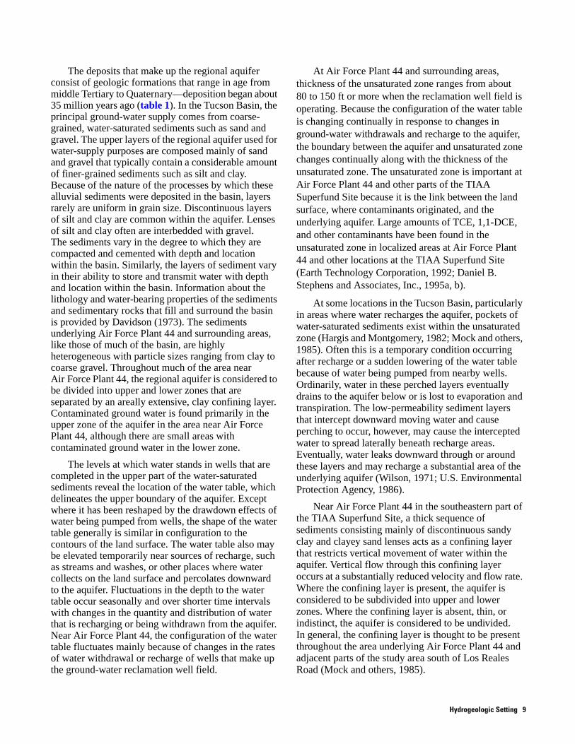
The deposits that make up the regional aquifer consist of geologic formations that range in age from middle Tertiary to Quaternary—deposition began about 35 million years ago (table 1). In the Tucson Basin, the principal ground-water supply comes from coarse-grained, water-saturated sediments such as sand and gravel. The upper layers of the regional aquifer used for water-supply purposes are composed mainly of sand and gravel that typically contain a considerable amount of finer-grained sediments such as silt and clay. Because of the nature of the processes by which these alluvial sediments were deposited in the basin, layers rarely are uniform in grain size. Discontinuous layers of silt and clay are common within the aquifer. Lenses of silt and clay often are interbedded with gravel. The sediments vary in the degree to which they are compacted and cemented with depth and location within the basin. Similarly, the layers of sediment vary in their ability to store and transmit water with depth and location within the basin. Information about the lithology and water-bearing properties of the sediments and sedimentary rocks that fill and surround the basin is provided by Davidson (1973). The sediments underlying Air Force Plant 44 and surrounding areas, like those of much of the basin, are highly heterogeneous with particle sizes ranging from clay to coarse gravel. Throughout much of the area near Air Force Plant 44, the regional aquifer is considered to be divided into upper and lower zones that are separated by an areally extensive, clay confining layer. Contaminated ground water is found primarily in the upper zone of the aquifer in the area near Air Force Plant 44, although there are small areas with contaminated ground water in the lower zone.
The levels at which water stands in wells that are completed in the upper part of the water-saturated sediments reveal the location of the water table, which delineates the upper boundary of the aquifer. Except where it has been reshaped by the drawdown effects of water being pumped from wells, the shape of the water table generally is similar in configuration to the contours of the land surface. The water table also may be elevated temporarily near sources of recharge, such as streams and washes, or other places where water collects on the land surface and percolates downward to the aquifer. Fluctuations in the depth to the water table occur seasonally and over shorter time intervals with changes in the quantity and distribution of water that is recharging or being withdrawn from the aquifer. Near Air Force Plant 44, the configuration of the water table fluctuates mainly because of changes in the rates of water withdrawal or recharge of wells that make up the ground-water reclamation well field.
At Air Force Plant 44 and surrounding areas, thickness of the unsaturated zone ranges from about 80 to 150 ft or more when the reclamation well field is operating. Because the configuration of the water table is changing continually in response to changes in ground-water withdrawals and recharge to the aquifer, the boundary between the aquifer and unsaturated zone changes continually along with the thickness of the unsaturated zone. The unsaturated zone is important at Air Force Plant 44 and other parts of the TIAA Superfund Site because it is the link between the land surface, where contaminants originated, and the underlying aquifer. Large amounts of TCE, 1,1-DCE, and other contaminants have been found in the unsaturated zone in localized areas at Air Force Plant 44 and other locations at the TIAA Superfund Site (Earth Technology Corporation, 1992; Daniel B. Stephens and Associates, Inc., 1995a, b).
At some locations in the Tucson Basin, particularly in areas where water recharges the aquifer, pockets of water-saturated sediments exist within the unsaturated zone (Hargis and Montgomery, 1982; Mock and others, 1985). Often this is a temporary condition occurring after recharge or a sudden lowering of the water table because of water being pumped from nearby wells. Ordinarily, water in these perched layers eventually drains to the aquifer below or is lost to evaporation and transpiration. The low-permeability sediment layers that intercept downward moving water and cause perching to occur, however, may cause the intercepted water to spread laterally beneath recharge areas. Eventually, water leaks downward through or around these layers and may recharge a substantial area of the underlying aquifer (Wilson, 1971; U.S. Environmental Protection Agency, 1986).
Near Air Force Plant 44 in the southeastern part of the TIAA Superfund Site, a thick sequence of sediments consisting mainly of discontinuous sandy clay and clayey sand lenses acts as a confining layer that restricts vertical movement of water within the aquifer. Vertical flow through this confining layer occurs at a substantially reduced velocity and flow rate. Where the confining layer is present, the aquifer is considered to be subdivided into upper and lower zones. Where the confining layer is absent, thin, or indistinct, the aquifer is considered to be undivided. In general, the confining layer is thought to be present throughout the area underlying Air Force Plant 44 and adjacent parts of the study area south of Los Reales Road (Mock and others, 1985).
Hydrogeologic Setting 9

Table 1. Geologic units and components of the Tucson regional-aquifer system and their environmental significance at Air Force Plant 44, Tucson, Arizona
[Modified from Anderson, 1987]
Geologic age Stratigraphic unitsComponents of the Tucson regional-aquifer system and their environmental
significance
QU
AT
ER
NA
RY
Holocene
Alluvium of the University, Cemetery, and Jaynes terraces
Unconformity Unsaturated zone—Water only partially fills the voids between sediment particles. Consists principally of alluvial stream and flood-plain deposits. In many places, sediments of the Fort Lowell Formation constitute part of the unsaturated zone. Beneath and near stream channels, the alluvial deposits may be saturated with water and constitute the capillary fringe and upper part of the regional aquifer. At Air Force Plant 44, some contaminants that originated at the land surface now reside in the unsaturated zone.Pleistocene
Fort Lowell Formation
Unconformity
TE
RT
IAR
Y
Pliocene
Upper Tinaja beds Capillary fringe—Water held by capillary forces fills the voids between sediment particles immediately above the water table. Thickest where sediments are fine grained and in locations where recharge from above occurs. Thinnest where sediments are coarse grained or where no recharge from above occurs. Contaminants trapped in fine-grained sediments in the capillary fringe may be particularly resistant to removal.
Unconformity Tucson regional aquifer—Upper limit is the water table. Lower limit and horizontal boundaries are the bottom and edges of the Tucson Basin, respectively. In the central part of the Tucson basin, the regional aquifer may be subdivided into upper and lower aquifer zones, which are separated by a confining unit consisting of clayey silt to sandy clay of the upper Tinaja. The confining unit, where present, slows water movement between the upper and lower aquifer zones. The confining unit is present throughout Air Force Plant 44, where suspected sources of TCE contamination are located; in the western to northwestern portions of the Tucson International Airport Area Superfund Site, the aquifer is undivided. Sediments that make up the regional aquifer become progressively more consolidated with depth. Well yields tend to decrease with increasing depth below land surface; generally only the upper 1,000 ft of the aquifer is used as a water source. At greater depths, water quality commonly is less suitable for potable uses.
Miocene
Middle Tinaja beds
Unconformity
Lower Tinaja Beds
Unconformity
Oligocene
Pantano Formation
Unconformity
Eocene and older
Pre-Oligocene igneous, metamorphic, and sedimentary rocks
Confining unit—Restricts flow of ground water into or out of the regional aquifer.
10 TCE and 1,1-DCE Concentrations in Ground Water, Air Force Plant 44, Tucson, Arizona

At Air Force Plant 44 and throughout much of the TIAA Superfund Site, the upper zone of the regional aquifer is about 70 to 120 ft thick and extends from the water table to a depth of 200 to 220 ft below the land surface. The upper zone consists of sand and gravel layers and thin, discontinuous layers of clayey, silty sediments that do not transmit water readily. At Air Force Plant 44, contaminated ground water is found mainly in the mixed sediments of the upper zone of the regional aquifer. The upper zone of the regional aquifer at Air Force Plant 44 is underlain by a thick sequence of clayey sediments, which extends to depths ranging from about 300 to 350 ft below land surface. This confining layer generally has a thickness of 100 ft or more at Air Force Plant 44. Beneath the confining layer, at depths ranging from about 300 to 350 ft below land surface, is the top of the lower zone of the regional aquifer. Sediments in the lower zone consist of clayey sand and sandy clay, and occasional thin layers of gravel or sand. The sediments of the lower zone contain more clay, are more poorly sorted, and are more heavily cemented than in the upper zone and, therefore, do not store and transmit water as readily (Davidson, 1973).
In general, the aquifer contains more fine-grained sediments in the southeastern part of the TIAA Superfund Site, near Air Force Plant 44, than in the northwestern part. In some parts of the TIAA Superfund Site, the upper zone of the regional aquifer appears to be further subdivided because of layers of fine-grained sediments; however, these layers are continuous only for short distances. Similarly, the confining layer may contain layers of coarse-grained sediments that are continuous only for short distances. The layered, interlaced nature of the sedimentary deposits that make up the regional aquifer, particularly where the confining layer is present, has a distinct effect on the way that water moves through the water-saturated sediments—horizontal water movement occurs much more readily than vertical movement (Wilson, 1971). Although downward hydraulic potential created by regional water withdrawals occurs throughout the area occupied by Air Force Plant 44, downward water movement is impeded where the confining layer is present and not breached by wells.
Water Movement in the Regional Aquifer at Air Force Plant 44
In a water-table aquifer like that of the Tucson Basin, ground water moves in response to gravity, moving laterally from areas where the altitude of the water table is high to areas where it is lower. Often this is in the direction of the overlying surface drainage such as along streams and washes. Where ground-water withdrawals have lowered the water table and created localized depressions, water moves from surrounding areas toward the centers of the depressions.
Near Air Force Plant 44 the water table slopes to the northwest, except where pumping has created localized depressions or where injection wells that are operated for purposes of cleanup have created recharge mounds. The configuration of the water table in areas where drawdown cones and recharge mounds have been created by cleanup efforts is changing continually in response to changes made to the distribution of water removal and reinjection to the aquifer. Local variations in the direction of ground-water flow are common because of the effects of nearby pumped wells. South of Los Reales Road, extraction wells operated for cleanup purposes have created several steep, and sometimes overlapping, drawdown cones (Groundwater Resources Consultants, Inc., 1998). The configuration, depth, and lateral extent of these drawdown cones vary continually with changes in the distribution and withdrawal rates of the extraction wells. The distribution and recharge rates of wells of the reclamation well field also have an effect on the movement of water in the aquifer. The combined effects of extraction wells near the axis of the TCE contaminant plume and recharge wells located outside the perimeter of the contaminant plume are intended to create a “capture zone” that minimizes movement of ground water from areas where it is contaminated. North of Los Reales Road, the overall lateral direction of ground-water movement is toward the northwest.
At Air Force Plant 44, depth to water in wells completed in the upper zone of the regional aquifer ranges from about 80 to 150 ft. In May 1999, extraction and injection wells of the reclamation well field were shut down for about 3 weeks before water levels were measured throughout the site; dates of measurement, depth to water, and water-level altitude above sea level are given in Groundwater Resources Consultants, Inc. (1999, appendix B-1). The configuration of the water
Hydrogeologic Setting 11

table at Air Force Plant 44 after shutdown of extraction and injection wells at the reclamation well field in May 1999 indicates a slight gradient to the northwest (fig. 4). Although the water-table configuration shown in figure 4 represents close-to-static conditions, areas of water-level depression created by past pumping and ground-water mounding created by past recharge of treated water by injection wells at the reclamation well field have not fully dissipated, and subdued remnants of these features are present.
GROUND-WATER CLEANUP AT AIR FORCE PLANT 44
In recent years, much effort and expense has been directed toward minimizing the adverse environmental consequences of historical-disposal practices and cleaning up ground-water contamination at Air Force Plant 44 and adjacent areas. Permanent aquifer restoration requires that contaminants be removed from the sediments above the water table as well as from the aquifer. Major ground-water cleanup activities initiated at Air Force Plant 44 include: construction and operation of a network of extraction and recharge wells, used in conjunction with a large-scale treatment facility for the part of the TIAA Superfund Site south of Los Reales Road, where large concentrations of TCE and 1,1-DCE in ground water are found in some locations; and removal of these VOCs from sediments of the unsaturated zone that lie above the water table near disposal areas.
In general, TCE, 1,1-DCE, and other VOCs that are dissolved in ground water are removed by extracting water from the aquifer and aerating it to allow the VOCs to escape into the air; the VOCs are then recaptured by passing the air through an absorbing material such as granular-activated carbon. Removal of VOCs from the unsaturated zone is accomplished by pumping out air containing VOCs in the vapor phase and capturing the VOCs by passing the air through an absorbing material.
Removal of Volatile Organic Compounds from Ground Water
A reclamation well field consisting of a network of extraction and recharge wells (fig. 5) and a ground-water treatment facility were put into operation to contain the spread of the part of the contaminant plume that is south of Los Reales Road and treat the contaminated ground water. This pump-and-treat facility has been operating since 1987. A network of
21 wells perforated in the upper zone of the regional aquifer and 4 wells perforated in the underlying lower zone of the regional aquifer is used to extract contaminated ground water. The ground water is then processed at the treatment facility and returned to the aquifer through a network of 22 recharge wells at the periphery of the contaminant plume south of Los Reales Road. Contaminated ground water is found principally in the upper zone of the regional aquifer; for this reason, most of the water that is extracted for cleanup purposes is from the upper zone. All of the recharge wells are perforated in the upper zone of the regional aquifer; two of these wells also are perforated in the lower zone of the regional aquifer. Construction details of wells that are part of the reclamation well field are given in Groundwater Resources Consultants, Inc. (1999, Appendix E-1).
Another component of the ground-water cleanup effort is a network of 41 wells completed in fine-grained saturated sediments in an area of approximately 100 acres in the northwest corner of Air Force Plant 44 (Haley and Aldrich, Inc., 2000). This network of ground-water and vapor-extraction wells was put in operation in April 1997. In this area, the water table is considerably higher than in surrounding areas and has been designated as the shallow ground-water zone (formerly known as the perched zone in many site-related documents). The sediments in which these wells are completed consist of clay, sandy clay, and clayey sand. The wells yield only small quantities of water and vapor and, therefore, were not sampled in this study. Only small quantities of VOCs are removed from sediments in this area because pumping rates of extraction wells are low (Haley and Aldrich, Inc., 2000).
The ground-water treatment facility consists principally of air-stripping towers where ground water is brought into contact with air to allow VOCs to volatilize and granular-activated carbon sorption units to recapture the volatilized contaminants from the air stream. When the capacity of the carbon to hold the contaminants is used up, the carbon is replaced. Total cumulative volume of ground water extracted and treated from April 1987 through June 1998 was about 16.911 billion gallons (51,899 acre-ft). An estimated 20,000 lbs of VOCs, primarily TCE, have been removed from ground water at the facility. More than 98 percent of the ground water extracted from the regional aquifer through operation of the reclamation well field was recharged to the upper zone of the regional aquifer after treatment (Groundwater Resources Consultants, Inc., 1998).
12 TCE and 1,1-DCE Concentrations in Ground Water, Air Force Plant 44, Tucson, Arizona, 1999

Nogales H
ighway
Hughes Access
Los Reales Road
M-22A
TucsonInternational
Airport
SF-5
M-35
E-7
R-23
EPA-5
EPA-3
EPA-2
EPA-1E-4
M-38R-9
E-5
R-5
E-18
R-4R-3
E-13
R-7
R-22
R-8
M-39
M-37
M-32
E-3
M-31
M-30
M-33
M-6
M-23
E-19
E-15M-13
E-24E-1
M-24A
M-80 M-60
M-77
M-17
M-18
M-19
M-75M-59M-50 M-21
M-74 M-71
M-70
M-14
M-79
M-78
M-15
M-9M-10
M-41
M-16
M-25R-13R-12
M-3A
E-17
E-23
R-14
R-15E-20
E-10
E-16
M-56 M-55A
M-28
R-14A
R-2
M-12A M-7M-8
M-2B
M-34
EPA-4
M-5M-20
E-8
M-36
E-12
E-14
E-21
M-11
Modified from Groundwater Resources Consultants, Inc. (1999)
CreditUnion
Air ForcePlant 44
R-6
R-10
Herman Road
BOUNDARY OF TOHONO O'ODHAM NATION
AIR FORCE PLANT 44 BOUNDARY
CONTOUR OF EQUAL WATER-LEVEL ALTITUDE, IN FEET ABOVE MEAN SEA LEVEL—Interval 5 feet
HACHURES INDICATE AREA OF DEPRESSION
UPPER ZONE MONITOR WELL—Letter and number are well identifier
RECLAMATION WELL—Letter and number are well identifier; "E" denotes extraction well, "R" denotes recharge well
EXPLANATION
Tohono O'OdhamNation
(San XavierDistrict)
2,450
2,45
5
2,460
2,470 2,
475
2,465
2,480
2,485
2490
,
2 465,
249
5,
2
2
2 4 6 5,
2 4 6 5,
465,
490
,
N
0
0
500 METERS250
2,000 FEET1,000
M-37
M-1A
R-6
Figure 4. Configuration of the water table, upper zone of the regional aquifer, May 1999, after temporary shutdown of reclamation well field, Air Force Plant 44, Tucson, Arizona. measurements made May 3 to May 24, 1999.
Ground-Water Cleanup at Air Force Plant 44 13

Nogales H
ighway
Hughes Access
Los Reales Road
TucsonInternational
Airport
E-7
R-23
E-4R-9
E-5
R-5
E-18
R-4
R-3
E-13
R-7
R-7
R-22
R-8
E-19
E-15
E-24E-1
R-20
R-21
R-17
M-9
M-9
M-16
R-13R-12
R-19R-18
E-17
E-23
R-14
R-15
E-20
E-10
E-16
R-14A
R-1
R-2M-12A
SC-7
E-2
M-5M-20
E-8,E-8M
E-3,E-3M
E-12
E-14
E-21
M-8
Modified from Groundwater Resources Consultants, Inc. (1999)
EXPLANATION
SC-7
E-20
Tohono O'odhamNation
(San XavierDistrict)
BOUNDARY OF TOHONO O'ODHAM NATION
AIR FORCE PLANT 44 BOUNDARY
EXTRACTION WELL —Letter and number are well identifier
RECHARGE WELL—Letter and number are well identifier
WELL USED TO TEST REDUCED-FLOW SAMPLING TECHNIQUES—Letter and number are well identifier
WELL USED TO DETERMINE VARIATIONS OF CONTAMINANT CONCENTRATIONS WITH DEPTH—Letter and number are well identifier
EXTRACTION WELL USED TO DETERMINE VARIATIONS OF CONTAMINANT CONCENTRATIONS WITH DEPTH—Letter and number are well identifier
E-4
N
0
0
500 METERS250
2,000 FEET1,000
EL-3EL-2
EL-1
EL-4
R-6
R-10
Air ForcePlant 44
Figure 5. Location of extraction and recharge wells at the reclamation well field, wells used to test reduced-flow sampling techniques, and well sampled to determine variations of contaminant concentrations with depth, Air Force Plant 44, Tucson, Arizona.
14 TCE and 1,1-DCE Concentrations in Ground Water, Air Force Plant 44, Tucson, Arizona

Removal of Volatile Organic Compounds from the Unsaturated Zone
At Air Force Plant 44, VOCs are being removed from the unsaturated zone in conjunction with removal of VOCs from the underlying aquifer. In August 1994, cleanup of several areas at Air Force Plant 44 that were contaminated with TCE and other solvents was initiated using a dual-phase extraction (DPE) system, an enhancement to the existing ground-water reclamation system. The DPE system is intended to remove dissolved VOCs from ground water and VOCs as vapors from overlying sediments. The DPE system has been used with several wells perforated in the upper zone of the aquifer that are part of the pump-and-treat cleanup system at Air Force Plant 44 (Groundwater Resources Consultants, Inc., 1999). Ground water is extracted from the well and sent to the treatment facility for removal of VOCs while soil vapor is removed simultaneously from the unsaturated zone near the well and directed through onsite canisters of granular-activated carbon for removal of VOCs. A blower is used to create a vacuum in the well casing for removal of soil vapor. Soil vapor is extracted through openings in the well screen that are above the water table in the drawdown cone created when water is extracted from the well.
The DPE system has been used to remove large quantities of the VOCs from the subsurface at Air Force Plant 44. VOCs have been removed from the unsaturated zone at rates as high as several hundred pounds per month. The DPE system is used mainly where large amounts of VOCs remain in sediments above the water table near historical-disposal areas.
In several areas of Air Force Plant 44, TCE and other VOCs in vapor form are being removed from the unsaturated zone by means of a soil-vapor extraction (SVE) system. Air containing VOCs in the vapor phase is pumped from more than a hundred shallow wells completed in the unsaturated zone near disposal areas by using vapor-extraction blower units. Contaminants are removed by passing the evacuated air stream through canisters containing granular-activated carbon. By the end of 1998, it is estimated that more than 100,000 lbs of VOCs, mainly TCE, were removed from the unsaturated zone by using the DPE and SVE systems.
CHEMICAL ANALYSES USED TO DETERMINE CONCENTRATIONS OF TRICHLOROETHYLENE AND 1,1-DICHLOROETHYLENE IN GROUND WATER
Samples of ground water collected for the various components of this study were analyzed at an onsite laboratory at Air Force Plant 44 operated by Raytheon. The onsite laboratory is certified by the ADHS and uses analytical methods approved by the USEPA. A total of 25 sample splits were obtained by USGS personnel at selected wells and sent to a USGS-approved contract laboratory (Quanterra Labs, Arvada, Colorado) for independent analyses of concentrations of TCE, 1,1-DCE, and other VOCs using USEPA Method 8021b. In general, concentrations of TCE and 1,1-DCE in sample splits sent to the USGS-approved contract laboratory were the same as, or slightly lower than those determined at the onsite laboratory. Data obtained from the onsite laboratory at Air Force Plant 44 are presented in tables 2–5; data obtained for sample splits sent to the contract laboratory are presented in tables 4 and 5. Because it is the more complete data set, and for reasons of consistency, data obtained from the onsite laboratory are used to delineate the TCE and 1,1-DCE contaminant plumes and in the discussions of results of the various components of this investigation.
SITEWIDE GROUND-WATER SAMPLING TO DETERMINE CONCENTRATIONS OF TRICHLOROETHYLENE AND 1,1-DICHLOROETHYLENE AFTER TEMPORARY SHUTDOWN OF RECLAMATION WELL FIELD
Monitoring for concentrations of TCE and other VOCs in ground water has been done on a regular basis at Air Force Plant 44 and surrounding areas since the early 1980s. Data from this monitoring have been used to characterize the extent and magnitude of ground-water contamination and to observe changes in ground-water quality associated with operation of the reclamation well field. Since startup of the reclamation well field in 1987, ground-water monitoring has been done while the extraction and recharge wells of the reclamation well field were operating. Because many of the monitor wells are located in areas where ground-water levels and flow directions are affected by operation of the reclamation well field, samples collected in this manner are representative of VOC
Results of Ground-Water Sampling After Shutdown of the Reclamation Well Field 15

concentrations in the aquifer under pumping conditions. The data might not be representative of concentrations under nonpumping conditions, and, therefore, may not be a completely accurate portrayal of cleanup progress. Although concentrations were expected to be similar or identical under pumping and nonpumping conditions in many locations, previous investigations in some locations (Brusseau and others, 1996a, b) indicated that a pronounced rebound of contaminant concentrations might occur with the shutdown. In order to obtain VOC concentration data under near-equilibrium conditions, the reclamation well field was shut down for sufficient time to allow water levels to recover and VOC concentrations to rebound. Previous studies at Air Force Plant 44 in which rebound of concentrations of TCE were observed (Brusseau and others, 1996b) suggested that a period of about 3 weeks would be sufficient to observe significant rebound. Concentrations of VOCs were determined for samples of ground water obtained from 101 wells from February 1 to March 4, 1999, during pumping conditions, for comparison with samples taken at the study area under nonpumping conditions.
The ground-water treatment plant and reclamation well field at Air Force Plant 44 was shut down on April 15, 1999. Sitewide ground-water sampling was done by personnel from Raytheon and Groundwater Resources Consultants, Inc. Sampling and sample-handling protocols were used for ground-water monitoring at the site. Samples were collected after purging three casing volumes of water from each well as pH, electrical conductivity, and temperature were monitored. Samples were collected after confirming that successive measurements of these field properties showed negligible change. USGS personnel observed sample collection and obtained sample splits at selected monitor wells. Samples were collected from all monitor and extraction wells that normally are sampled during annual monitoring rounds required by the USEPA. From May 3 to May 25, 1999, 102 wells were sampled at the site to determine the distribution of TCE and 1,1-DCE in ground water after shutdown of extraction and recharge wells at the reclamation well field. Of the wells sampled, 90 are completed in the upper zone of the regional aquifer. Sample splits were collected at six of the wells sampled as part of the sitewide sampling effort. Sample splits were obtained at wells M-5, M-8, M-9, M-12A, M-16, and M-20.
Extraction wells are equipped with high-capacity submersible pumps and monitor wells are equipped with dedicated submersible sampling pumps. Most of the monitor wells are constructed of 4-inch-diameter
steel casing; extraction wells and other wells sampled, such as the Credit Union well, are constructed of 6- to 8-inch-diameter steel casing. Well-construction information, such as well diameter, total depth of borehole, depth cased, perforated interval, and cemented interval are detailed in Groundwater Resources Consultants, Inc. (1999, Appendix E, tables E-1 and E-3). Wells were purged a minimum of three casing-volumes before sampling. Flow rates for purging and sampling ranged from 1 to 44 gal/min, and most monitor wells were purged and sampled at rates of about 10 to 15 gal/min (Groundwater Resources Consultants, Inc., 1999, Appendix E, table E-3). Samples were collected after several successive measurements of field properties (pH, electrical conductivity, and temperature) showed negligible change. The sampling was scheduled so that wells at the periphery of the TCE plume were sampled first to allow maximum time for contaminant concentrations to rebound in more central areas of the plume where rebound was considered more likely. This sampling schedule also served to minimize the time that the reclamation well field needed to be shut down. Operation of the reclamation well field resumed on June 2, 1999, after sitewide sampling activities were completed.
RESULTS OF SITEWIDE GROUND-WATER SAMPLING TO DETERMINE CONCENTRATIONS OF TRICHLOROETHYLENE AND 1,1-DICHLOROETHYLENE AFTER TEMPORARY SHUTDOWN OF RECLAMATION WELL FIELD
Concentrations of TCE ranging from less than the analytical method reporting limit (0.5 µg/L) to 1,610 µg/L were determined for ground-water samples collected after shutdown of the reclamation well field (table 2). The highest concentrations of TCE were found in samples collected from extraction wells E-14 (1,610 µg/L) and E-16 (260 µg/L) and monitor wells M-18 (918 µg/L), M-5 (415 µg/L), M-17 (393 µg/L), and M-80 (381 µg/L). Samples were collected for analysis of TCE concentrations from 101 of the 102 wells from February to March 1999, before shutdown of the reclamation well field. Samples were collected again after the reclamation well field was shut down. Comparison of the 2 data sets showed that in samples collected after shutdown, concentrations of TCE increased in 36 wells, remained the same in 32 wells, and decreased in 33 wells (table 2).
16 TCE and 1,1-DCE Concentrations in Ground Water, Air Force Plant 44, Tucson, Arizona, 1999

Table 2. Comparison of trichloroethylene (TCE) concentrations in ground water before and after temporary shutdown of reclamation well field, Air Force Plant 44, Tucson, Arizona
[TCE, trichloroethylene; <, less than; ---, not calculated; M, monitoring well; E, extraction well; R, recharge well; NA, not available]
Well number
Zone of regional aquifer
Samples collected before shutdown of reclamation-well field
Samples collected after shutdownof reclamation-well field
Net change(percent)
Net change, in micrograms
per literDate
TCEconcentration, in
micrograms per liter Date
TCEconcentration, in
micrograms per liter
M-18 Upper 02–24–99 3,210 05–13–99 918 -71 -2,292
M-20 Upper 02–09–99 1,910 05–10–99 7.5 -100 -1,902.5
M-17 Upper 02–15–99 607 05–13–99 393 -35 -214
E-21 Upper 02–19–99 328 05–24–99 130 -60 -198
M-64 Upper1 02–15–99 392 05–13–99 221 -44 -171
E-20 Upper 02–04–99 113 05–20–99 24 -79 -89
M-80 Upper 02–15–99 438 05–14–99 381 -13 -57
M-23 Upper 02–22–99 111 05–12–99 64 -42 -47
E-12 Upper 02–19–99 69 06–03–99 24 -65 -45
M-3B Lower 02–16–99 76 05–17–99 38 -50 -38
M-10 Upper 02–22–99 98 05–12–99 63 -36 -35
M-68 Upper1 02–09–99 111 05–17–99 79 -29 -32
E-13 Upper 02–19–99 38 05–24–99 7.3 -81 -30.7
M-8 Upper 02–22–99 134 05–10–99 105 -22 -29
M-5 Upper 02–08–99 436 05–10–99 415 -5 -21
E-3 Upper 02–23–99 17 05–21–99 1.3 -92 -15.7
M-2B Upper 02–16–99 65 05–13–99 50 -23 -15
E-4 Upper 02–23–99 18 05–20–99 4.1 -77 -13.9
EL-1 Lower 02–19–99 9.2 05–20–99 <.5 --- ---
E-7 Upper 02–24–99 10 05–21–99 1.1 -89 -8.9
M-41 Upper 03–04–99 269 05–21–99 265 -1 -4
M-67 Upper1 02–09–99 6.1 05–17–99 3.5 -43 -2.6
M-11 Upper 02–08–99 8.6 05–12–99 6.4 -26 -2.2
EPA-2A2 Lower 02–11–99 8.8 05–19–99 6.9 -22 -1.9
M-63 Upper1 02–03–99 2.6 05–04–99 1.4 -46 -1.2
M-61 Upper1 02–24–99 2.3 05–14–99 1.1 -52 -1.2
E-24 Upper 02–23–99 44 05–21–99 43 -2 -1
M-6 Upper 02–04–99 1.4 05–06–99 .7 -50 -.7
M-24A Upper 02–15–99 6.5 05–12–99 5.9 -9 -.6
EPA-52 Upper 02–09–99 6.4 05–17–99 6 -6 -.4
M-14 Upper 02–01–99 1 05–03–99 .6 -40 -.4
EPA-42 Upper 02–10–99 3.5 05–18–99 3.1 -11 -.4
M-70 Upper 02–05–99 7.7 05–13–99 7.4 -4 -.3
Credit Union2
Upper 02–10–99 14 05–20–99 14 0 0
E-17 Upper 02–23–99 29 05–21–99 29 0 0
E-18 Upper 02–19–99 61 05–21–99 61 0 0
See footnotes at end of table.
Results of Sitewide Ground-Water Sampling to Determine Concentrations of TCE and 1,1-DCE in Ground Water 17

Table 2. Comparison of trichloroethylene (TCE) concentrations in ground water before and after temporary shutdown of reclamation well field, Air Force Plant 44, Tucson, Arizona—Continued
Well number
Zone of regional aquifer
Samples collected before shutdown of reclamation-well field
Samples collected after shutdown of reclamation-well field
Net change(percent)
Net change, in micrograms
per literDate
TCEconcentration, in
micrograms per liter Date
TCEconcentration, in
micrograms per liter
EPA-22 Upper 02–22–99 <.5 05–18–99 <.5 0 0
M-1A Upper 02–04–99 <.5 05–06–99 <.5 0 0
M-1B Lower 02–15–99 <.5 05–13–99 <.5 0 0
M-2C Lower 02–23–99 <.5 05–24–99 <.5 0 0
M-12B Lower 02–22–99 8.7 05–17–99 8.7 0 0
M-15 Upper 02–01–99 <.5 05–03–99 <.5 0 0
M-19 Upper 02–02–99 <.5 05–04–99 <.5 0 0
M-21 Upper 02–03–99 <.5 05–04–99 <.5 0 0
M-22A Upper 02–01–99 <.5 05–03–99 <.5 0 0
M-22B Lower 02–01–99 <.5 05–03–99 <.5 0 0
M-24B Lower 02–05–99 <.5 05–12–99 <.5 0 0
M-25 Upper 02–02–99 1 05–06–99 1 0 0
M-27 Lower 02–04–99 <.5 05–13–99 <.5 0 0
M-29 Lower 02–05–99 <.5 05–06–99 <.5 0 0
M-30 Upper 02–04–99 <.5 05–06–99 <.5 0 0
M-31 Upper 02–04–99 <.5 05–06–99 <.5 0 0
M-32 Upper 02–03–99 <.5 05–06–99 <.5 0 0
M-33 Upper 02–05–99 <.5 05–18–99 <.5 0 0
M-37 Upper 02–10–99 <.5 05–18–99 <.5 0 0
M-38 Upper 02–10–99 <.5 05–18–99 <.5 0 0
M-39 Upper 02–10–99 <.5 05–18–99 <.5 0 0
M-56 Upper 02–01–99 <.5 05–03–99 <.5 0 0
M-58 Upper 02–03–99 <.5 05–04–99 <.5 0 0
M-59 Upper 02–03–99 <.5 05–04–99 <.5 0 0
M-60 Upper 02–04–99 <.5 05–04–99 <.5 0 0
M-62 Upper1 02–03–99 <.5 05–04–99 <.5 0 0
M-71 Upper 02–03–99 <.5 05–04–99 <.5 0 0
M-74 Upper 02–03–99 <.5 05–04–99 <.5 0 0
M-79 Upper 02–01–99 <.5 05–03–99 <.5 0 0
M-55A Upper 02–02–99 1.2 05–03–99 1.3 8 .1
EPA-12 Upper 02–10–99 3.6 05–18–99 3.9 8 .3
M-78 Upper 02–02–99 2.1 05–04–99 2.4 14 .3
M-35 Upper 02–05–99 1.5 05–06–99 1.8 20 .3
M-26 Lower 02–11–99 5.9 05–17–99 6.3 7 .4
M-75 Upper 02–24–99 3.6 05–14–99 4.1 14 .5
COBB3 Upper 02–16–99 .7 05–25–99 1.3 86 .6
M-28 Upper 11–06–98 4.1 05–07–99 4.7 15 .6
M-13 Upper 02–08–99 6.1 05–12–99 6.8 11 .7
E-1 Upper 02–23–99 6.1 05–20–99 7 15 .9
M-7 Upper 02–08–99 20 05–14–99 21 5 1
M-16 Upper 02–15–99 12 05–10–99 13 8 1
See footnotes at end of table.
18 TCE and 1,1-DCE Concentrations in Ground Water, Air Force Plant 44, Tucson, Arizona

Well number
Zone of regional aquifer
Samples collected before shutdown of reclamation-well field
Samples collected after shutdown of reclamation-well field
Net change(percent)
Net change, in micrograms
per literDate
TCEconcentration, in
micrograms per liter Date
TCEconcentration, in
micrograms per liter
M-40 Upper 11–13–98 7.6 05–14–99 8.6 13 1
JACK3 Upper 02–16–99 1.9 05–25–99 3.3 74 1.4
SF-51 Upper 02–17–99 11 05–19–99 13 18 2
EPA-3 Upper 02–10–99 1.8 05–14–99 4.6 156 2.8
E-8 Upper 02–24–99 11 05–21–99 14 27 3
EL-2 Lower 02–19–99 45 05–20–99 48 7 3
M-9 Upper 02–22–99 44 05–10–99 49 11 5
M-12A Upper 02–08–99 17 05–10–99 22 29 5
M-36 Upper 02–15–99 .5 05–14–99 7 1,300 6.5
EL-3 Lower 02–19–99 15 05–21–99 27 80 12
R-12M Upper 02–22–99 11 05–19–99 24 118 13
E-23 Upper 02–23–99 53 05–21–99 69 30 16
R-13M Upper 02–23–99 7.4 05–19–99 26 251 18.6
M-77 Upper 02–15–99 132 05–14–99 153 16 21
R-14AM Upper 11–18–98 11 05–19–99 34 209 23
E-2 Upper 02–23–99 55 05–21–99 79 44 24
EL-4 Lower 02–19–99 3.2 05–21–99 28 775 24.8
E-19 Upper 02–19–99 75 05–24–99 136 81 61
M-3A Upper 02–16–99 46 05–20–99 141 207 95
E-15 Upper 02–19–99 90 05–12–99 234 160 144
M-69 Upper1 02–19–99 66 05–21–99 213 223 147
E-10 Upper 02–04–99 18 05–19–99 200 1,011 182
E-16 Upper 02–04–99 19 05–20–99 260 1,268 241
E-14 Upper 02–04–99 134 05–20–99 1,610 1,101 1,476
M-65 Upper1 NA NA 05–13–99 59 --- ---1Wells M-61, M-62, M-63, M-64, M-65, M-67, M-68, and M-69 are selectively screened wells in well clusters. Data from these wells were not used to contour dichloroethylene
concentrations in figures 9 and 10 because they are representative of only selective small intervals of the upper zone of the regional aquifer.2Monitor well.3Private well.
Table 2. Comparison of trichloroethylene (TCE) concentrations in ground water before and after temporary shutdown of reclamation well field, Air Force Plant 44, Tucson, Arizona—Continued
Increases in concentrations of TCE after shutdown ranged from 0.1 µg/L to 1,476 µg/L. The largest increases in concentrations of TCE were found in extraction wells E-14, E-16, and E-10; increases in these wells after shutdown were 1,476 µg/L, 241 µg/L, and 182 µg/L, respectively. Decreases ranged from 0.3 µg/L to 2,292 µg/L. The largest decreases in concentrations of TCE were found in monitor wells M-17, M-18, and M-20; decreases in these wells after shutdown were 214 µg/L, 2,292 µg/L, and 1,902 µg/L, respectively. Wells showing the largest changes in TCE concentrations are all completed in the upper zone of
the regional aquifer. Concentrations of TCE remained the same for the two sampling periods in most wells that had concentrations that were at, or close to, the lower reporting limit before shutdown. Other wells in which concentrations of TCE remained the same after shutdown include monitor wells M-12B and M-25, extraction wells E-17 and E-18, and the Credit Union well. Net change in concentrations of TCE after shutdown on a percentage basis ranged from an increase of 1,300 percent to a decrease of 100 percent (table 2). The areal distribution of wells having a change of apparent concentrations of TCE of 10 µg/L
Results of Sitewide Ground-Water Sampling to Determine Concentrations of TCE and 1,1-DCE in Ground Water 19

or more is shown in figure 6. In general, wells showing the largest change in concentrations of TCE are completed in the upper zone of the aquifer and are located in the central portion of Air Force Plant 44, near historical-disposal areas.
On the basis of samples obtained from 90 wells completed in the upper zone of the regional aquifer from February 1 to March 4, 1999, and from May 3 to May 25, 1999, the areal distribution of concentrations of TCE in ground water from wells completed in the upper zone before shutdown (fig. 7) generally was similar to the areal distribution after shutdown (fig. 8), although some wells inside the plume perimeter yielded water having markedly higher or lower concentrations of TCE. Minor changes in the delineated area of contamination after shutdown occurred, particularly in the northwestern part of the study area, because of small changes in concentrations of TCE in samples from wells at or near the plume perimeter. Large changes in concentrations of TCE occurring near identified source areas close to the axis of the plume had little effect on delineation of the plume perimeter.
Concentrations of 1,1-DCE ranging from less than the lower reporting limit (0.5 µg/L) to 113 µg/L were determined for samples of ground water collected after shutdown (table 3). The highest concentrations of 1,1-DCE were found in samples collected from monitor wells M-5 (113 µg/L), M-77 (71 µg/L), and M-69 (62 µg/L) and extraction wells E-14 (76 µg/L) and E-15 (46 µg/L). Samples were collected for analysis of 1,1-DCE concentrations from 101 of the 102 wells from February to March 1999, before shutdown of the reclamation well field. Samples were collected again after the reclamation well field was shut down. Comparison of the two data sets showed that increases in concentrations of 1,1-DCE after shutdown ranged from 0.2 µg/L to 66 µg/L. The largest increases in concentrations of 1,1-DCE were found in extraction wells E-14 and E-15 and monitor well M-69; increases in these wells after shutdown were 66 µg/L, 34 µg/L, and 44 µg/L, respectively. Decreases in concentrations of 1,1-DCE ranged from 0.1 µg/L to 411.6 µg/L. The largest decreases in concentrations of 1,1-DCE were found in monitor wells M-20 and M-80 and extraction well E-12; decreases in these wells after shutdown were 411.6 µg/L, 17 µg/L, and 17.8 µg/L, respectively. Wells showing the largest changes in
1,1-DCE concentrations are all completed in the upper
zone of the regional aquifer. Concentrations of 1,1-DCE remained the same for the two sampling
periods in 50 wells that had concentrations that were at, or close to, the lower reporting limit before shutdown.
Net change in concentrations of 1,1-DCE after shutdown on a percentage basis ranges from an
increase of 660 percent to a decrease of 100 percent
(table 3). In general, wells showing the largest change in concentrations of 1,1-DCE are in the central part of
Air Force Plant 44, close to previously identified historical-disposal areas.
On the basis of samples obtained from 81 wells
completed in the upper zone of the regional aquifer from February 1 to March 4, 1999, and from May 3 to
May 25, 1999, the areal distribution of concentrations
of 1,1-DCE in the upper zone before shutdown (fig. 9) generally is similar to the areal distribution after
shutdown (fig. 10), although some wells inside the plume perimeter yield water having markedly higher or
lower concentrations of 1,1-DCE. Minor changes in the delineated area of contamination after shutdown occur
because of small changes in concentrations of 1,1-DCE in samples from wells at or near the plume perimeter.
The largest changes in concentrations of 1,1-DCE
occur close to the axis of the plume; these changes have little effect on delineation of the plume perimeter.
Sitewide ground-water sampling after shutdown of
extraction and recharge wells of the reclamation well field indicated changes in apparent concentrations of
TCE and 1,1-DCE in ground water from many wells at the site. Large increases in contaminant concentrations
(rebound) after shutdown, however, were observed
only in wells near known historical disposal areas. Large increases in concentrations of TCE and 1,1-DCE
after shutdown were observed mainly in extraction wells along the axis of the contaminant plume in close
proximity to previously identified historical-disposal areas. Within the plume interior, there were no
indications of unexpected source areas, nor were major
modifications to the delineation of the plume perimeter indicated.
20 TCE and 1,1-DCE Concentrations in Ground Water, Air Force Plant 44, Tucson, Arizona, 1999

50
Nogales H
ighway
Hughes Access
Los Reales Road
TucsonInternational
Airport
E-4
EL-3
E-13
E-3
EL-4
M-23
E-19
E-15
M-77
M-17
M-18
M-10
R-13MR-12M
M-3AE-23M-8
M-3B
E-20
E-10
E-16
R-14MA
M-2B
E-2
M-5
M-20
E-12
E-14
E-21
Base from Groundwater Resources Consultants, Inc.
500
5
5
100
5
520 00
50
100200
0
0
0
TucsonInternational
Airport
Tohono O'odhamNation
(San XavierDistrict)
N
0
0
500 METERS250
2,000 FEET1,000
E-3M-17M-18
E-2E-16E-14
10
Air ForcePlant 44
EXPLANATION
BOUNDARY OF TOHONO O'ODHAM NATION
BOUNDARY OF AIR FORCE PLANT 44
CONTOUR OF EQUAL TRICHLOROETHYLENE CONCENTRATIONS, IN MICROGRAMS PER LITER, MAY 1999—Interval variable
DIFFERENCE IN CONCENTRATION OF TRICHLOROETHYLENE INCREASES—Letter and number are well identifier:
10 to 100 micrograms per liter 100 to 1,000 micrograms per liter Greater than 1,000 micrograms per liter
DIFFERENCE IN CONCENTRATION OF TRICHLOROETHYLENE DECREASES—Letter and number are well identifier:
10 to 100 micrograms per liter 100 to 1,000 micrograms per liter Greater than 1,000 micrograms per liter
Figure 6. Difference in concentration of trichloroethylene (TCE) in samples collected from wells in February 1999, before temporary shutdown of reclamation well field, and in samples collected in May 1999, after shutdown of well field; and contours of TCE concentration based on samples collected in May 1999. Only wells showing differences of 10 micrograms per liter or more are shown (see fig. 8 for location of other wells sampled).
Results of Sitewide Ground-Water Sampling to Determine Concentrations of TCE and 1,1-DCE in Ground Water 21

5
50
100
100200
500
50
Nogales H
ighway
Hughes Access
Los Reales Road
M-22A(ND)
TucsonInternational
Airport
SF-5(11)
M-35(1.5)
E-7(10)
EPA-5(6.4)
EPA-3(1.8)
EPA-2(ND)
EPA-1(3.6)
E-4(18)
M-38(ND)
E-18(61)
E-13(38)
M-39(ND) Jack
(1.9)
Cobb(0.7)
M-37(ND)
M-32(ND)
M-31(ND)
M-30(ND)
M-33(ND)
M-6(1.4)
M-23(111)
E-19(75)
E-15(90)
M-13(6.1)
E-24(44)
E-1(6.1)
M-24A(6.5)
M-80(438)
M-1A(ND)
M-60(ND)
M-28(4.1)
M-77(132)
M-17(607)
M-18(3,210)
M-19(ND)
M-75(3.6)M-59(ND) M-58(ND)
M-21(ND)
M-74 (ND) M-71(ND)
M-70(7.7)
M-14(1)
M-79(ND)
M-78(2.1)
M-15(ND)
M-9(44)
M-10(98)
M-41(269)
M-16(12)M-25(1)R-13M(7.4)R-12M
(11)
M-3A(46)
E-17(29)
E-23(53)
E-20(113)
R-14AM(11)
E-10(18)
E-16(19)
M-56(ND)M-55A(1.2)
1,000500100
M-12A(17)
M-7(20)M-8(134)
M-2B(65)
E-2 (55)
CreditUnion(14)
EPA-4(3.5)
M-40(7.6)
M-5(436)
M-20(1,910)
E-8(11)
M-36(ND)
E-12(69)
E-14(134)E-21(328)
M-11(8.6)
Modified from Groundwater Resources Consultants, Inc. (1999)
5
10
50
0 1,000
50 100200
500
Tohono O'odhamNation
(San XavierDistrict)
(2.1)
(ND)
Jack
MONITOR WELL IN UPPER ZONE OF REGIONAL AQUIFER-Letter and number are well identifier
TRICHLOROETHYLENE CONCENTRATION, IN MICROGRAMS PER LITER
LESS THAN MINIMUM REPORTING LIMIT (0.5 MICROGRAMS PER LITER)
PRIVATE WELL IN UPPER ZONE OF REGIONAL AQUIFER-Name is well identifier
RECLAMATION WELL—Letter and number are well identifier; "E" denotes extraction well, "R" denotes recharge well
1,000500200100505
N
0
0
500 METERS250
2,000 FEET1,000
E-3(17)
200
Air ForcePlant 44
EXPLANATION
BOUNDARY OF TOHONO O'ODHAM NATION
BOUNDARY OF AIR FORCE PLANT 44
CONTOUR OF EQUAL TRICHLOROETHYLENE CONCENTRATIONS, IN MICROGRAMS PER LITER—Interval variable
CONCENTRATIONS OF TRICHLOROETHYLENE, IN MICROGRAMS PER LITER
50
M-38
E-23
Figure 7. Concentrations of trichloroethylene (TCE) in ground water from the upper zone of the regional aquifer, February 1999, before temporary shutdown of reclamation well field, Air Force Plant 44, Tucson, Arizona.
22 TCE and 1,1-DCE Concentrations in Ground Water, Air Force Plant 44, Tucson, Arizona

5
50
100
50
Nogales H
ighway
Hughes Access
Los Reales Road
M-22A(ND)
TucsonInternational
Airport
SF-5(13)
M-35(1.8)
E-7(1.1)
EPA-5(6)
EPA-3(4.6)
EPA-2(ND)
EPA-1(3.9)
E-4(4.1)
M-38(ND)
E-18(61)
R-4
E-13(7.3)
M-39(ND) Jack
(3.3)
Cobb(1.3)
M-37(ND)
M-32(ND)
E-3 (1.3)
M-31(ND)
M-30(ND)
M-33(ND)
M-6(0.7)
M-23(64)
E-19(136)
E-15(234)
M-13(6.8)
E-24(43)
E-1(7)
M-24A(5.9)
M-80(381)
M-1A(ND)
M-60(ND)
M-77(153) E-12
(24)
M-17(393)
M-18(918)
M-19(ND)M-75(4.1)
M-59(ND)M-58(ND)
M-21(ND)
M-74(ND) M-71(ND)
M-70(7.4)
M-14(0.6)
M-79(ND)
M-78(2.4)
M-15 (ND)
M-9(49)
M-10(63)
M-41(265)
M-16(13)
M-25(1)
R-13M(26)
R-12M(24)
M-3A(141)
E-17(29)
E-23(69)
E-20(24)
E-10(200)
E-16(260)
M-56(ND) M-55A(1.3)
M-28(4.7)
R-14AM(34)
M-12A(22)
M-7(21)M-8
(105)M-2B(50)
E-2 (79)
M-40(8.6)
CreditUnion(14)
EPA-4(3.1)
M-5(415)
M-20(7.5)
E-8(14)
M-36(7)
E-14(1,610)
E-21(130)
M-11(6.4)
Modified from Groundwater Resources Consultants, Inc. (1999)
5
500200
5
100
0
Tohono O'odhamNation
(San XavierDistrict)
(2.4)
(ND)
Jack
MONITOR WELL IN UPPER ZONE OF REGIONAL AQUIFER-Letter and number are well identifier
TRICHLOROETHYLENE CONCENTRATION, IN MICROGRAMS PER LITER
LESS THAN MINIMUM REPORTING LIMIT (0.5 MICROGRAMS PER LITER)
PRIVATE WELL IN UPPER ZONE OF REGIONAL AQUIFER-Name is well identifier
RECLAMATION WELL-Letter and number are well identifier; "E" denotes extraction well, "R" denotes recharge well
1,000500200100505
N
0
0
500 METERS250
2,000 FEET1,000
E-4
Air ForcePlant 44
1001,000
5 20000
EXPLANATION
BOUNDARY OF TOHONO O'ODHAM NATION
BOUNDARY OF AIR FORCE PLANT 44
CONTOUR OF EQUAL TRICHLOROETHYLENE CONCENTRATIONS, IN MICROGRAMS PER LITER—Interval variable
CONCENTRATIONS OF TRICHLOROETHYLENE, IN MICROGRAMS PER LITER
50
M-32
Figure 8. Concentrations of trichloroethylene (TCE) in ground water from the upper zone of the regional aquifer, May 1999, after temporary shutdown of reclamation well field, Air Force Plant 44, Tucson, Arizona.
Results of Sitewide Ground-Water Sampling to Determine Concentrations of TCE and 1,1-DCE in Ground Water 23

Table 3. Comparison of 1,1-dichloroethylene (1,1-DCE) concentrations in ground water before and after temporary shutdown of reclamation well field, Air Force Plant 44, Tucson, Arizona
[1,1-DCE, 1,1-dichloroethylene; <, less than, ---, not calculated; M, monitoring well; E, extraction well; R, recharge well]
Well number
Zone of regional aquifer
Samples collected before shutdown of reclamation well field
Samples collected after shutdown of reclamation well field
Net change(percent)
Net change, in micrograms
per literDate
1,1-DCEconcentration, in
micrograms per liter Date
1,1-DCEconcentration, in
micrograms per liter
M-20 Upper 02–09–99 413 05–10–99 1.4 -100 -411.6
E-12 Upper 02–19–99 27 06–03–99 9.2 -66 -17.8
M-80 Upper 02–15–99 63 05–14–99 46 -27 -17
M-68 Upper1 02–09–99 33 05–17–99 21 -36 -12
M-10 Upper 02–22–99 38 05–12–99 27 -29 -11
E-21 Upper 02–19–99 17 05–24–99 9.6 -44 -7.4
E-13 Upper 02–19–99 8.2 05–24–99 .9 -89 -7.3
M-18 Upper 02–24–99 12 05–13–99 5.2 -57 -6.8
M-8 Upper 02–22–99 21 05–10–99 15 -29 -6
E-3 Upper 02–23–99 2 05–21–99 <.5 --- -2.5
E-24 Upper 02–23–99 9 05–21–99 6.6 -27 -2.4
E-4 Upper 02–23–99 2.7 05–20–99 .5 -81 -2.2
M-23 Upper 02–22–99 4.3 05–12–99 2.1 -51 -2.2
E-7 Upper 02–22–99 1 05–21–99 <.5 --- -1.5
R-12M Upper 02–22–99 .7 05–19–99 <.5 --- -1.2
M-9 Upper 02–22–99 4.3 05–10–99 3.4 -21 -.9
M-3B Lower 02–16–99 5 05–17–99 4.5 -10 -.5
M-64 Upper1 02–15–99 1.6 05–13–99 1.1 -31 -.5
M-2B Upper 02–16–99 10 05–13–99 9.6 -4 -.4
EPA-2A2 Lower 02–11–99 1.2 05–19–99 1.1 -8 -.1
M-11 Upper 02–08–99 .6 05–12–99 .6 0 0
COBB3 Upper 02–16–99 <.5 05–25–99 <.5 0 0
E-10 Upper 02–04–99 <.5 05–20–99 <.5 0 0
E-20 Upper 02–04–99 <.5 05–20–99 <.5 0 0
EL-1 Lower 02–19–99 <.5 05–20–99 <.5 0 0
EPA-22 Upper 02–22–99 <.5 05–18–99 <.5 0 0
JACK3 Upper 02–16–99 <.5 05–25–99 <.5 0 0
M-1A Upper 02–04–99 <.5 05–06–99 <.5 0 0
M-1B Lower 02–15–99 <.5 05–13–99 <.5 0 0
M-2C Lower 02–23–99 <.5 05–24–99 <.5 0 0
M-6 Upper 02–04–99 <.5 05–06–99 <.5 0 0
M-14 Upper 02–01–99 <.5 05–03–99 <.5 0 0
M-15 Upper 02–01–99 <.5 05–03–99 <.5 0 0
See footnotes at end of table.
24 TCE and 1,1-DCE Concentrations in Ground Water, Air Force Plant 44, Tucson, Arizona

Table 3. Comparison of 1,1-dichloroethylene (1,1-DCE) concentrations in ground water before and after temporary shutdown of reclamation well field, Air Force Plant 44, Tucson, Arizona—Continued
Well number
Zone of regional aquifer
Samples collected before shutdown of reclamation well field
Samples collected after shutdown of reclamation well field
Net change(percent)
Net change, in micrograms
per literDate
1,1-DCEconcentration, in
micrograms per liter Date
1,1-DCEconcentration, in
micrograms per liter
M-16 Upper 02–15–99 <.5 05–10–99 <.5 0 0
M-17 Upper 02–15–99 <.5 05–13–99 <.5 0 0
M-19 Upper 02–02–99 <.5 05–04–99 <.5 0 0
M-21 Upper 02–03–99 <.5 05–04–99 <.5 0 0
M-22A Upper 02–01–99 <.5 05–03–99 <.5 0 0
M-22B Upper 02–01–99 <.5 05–03–99 <.5 0 0
M-24A Upper 02–15–99 <0.5 05–12–99 <0.5 0 0
M-24B Lower 02–05–99 <.5 05–12–99 <.5 0 0
M-25 Upper 02–02–99 <.5 05–06–99 <.5 0 0
M-26 Lower 02–11–99 <.5 05–17–99 <.5 0 0
M-27 Lower 02–04–99 <.5 05–13–99 <.5 0 0
M-29 Lower 02–05–99 <.5 05–06–99 <.5 0 0
M-30 Upper 02–04–99 <.5 05–06–99 <.5 0 0
M-31 Upper 02–04–99 <.5 05–06–99 <.5 0 0
M-32 Upper 02–03–99 <.5 05–06–99 <.5 0 0
M-33 Upper 02–05–99 <.5 05–18–99 <.5 0 0
M-35 Upper 02–05–99 <.5 05–06–99 <.5 0 0
M-37 Upper 02–10–99 <.5 05–18–99 <.5 0 0
M-38 Upper 02–10–99 <.5 05–18–99 <.5 0 0
M-39 Upper 02–10–99 <.5 05–18–99 <.5 0 0
M-55A Upper 02–02–99 <.5 05–03–99 <.5 0 0
M-56 Upper 02–01–99 <.5 05–03–99 <.5 0 0
M-58 Upper 02–03–99 <.5 05–04–99 <.5 0 0
M-59 Upper 02–03–99 <.5 05–04–99 <.5 0 0
M-60 Upper 02–04–99 <.5 05–04–99 <.5 0 0
M-61 Upper1 02–24–99 <.5 05–14–99 <.5 0 0
M-62 Upper1 02–03–99 <.5 05–04–99 <.5 0 0
M-63 Upper1 02–03–99 <.5 05–04–99 <.5 0 0
M-67 Upper1 02–09–99 <.5 05–13–99 <.5 0 0
M-70 Upper 02–05–99 <.5 05–17–99 <.5 0 0
M-71 Upper 02–03–99 <.5 05–13–99 <.5 0 0
M-74 Upper 02–03–99 <.5 05–04–99 <.5 0 0
M-75 Upper 02–24–99 <.5 05–04–99 <.5 0 0
M-78 Upper 02–02–99 <.5 05–04–99 <.5 0 0
See footnotes at end of table.
Results of Sitewide Ground-Water Sampling to Determine Concentrations of TCE and 1,1-DCE in Ground Water 25

Well number
Zone of regional aquifer
Samples collected before shutdown of reclamation well field
Samples collected after shutdown of reclamation well field
Net change(percent)
Net change, in micrograms
per literDate
1,1-DCEconcentration., in
micrograms per liter Date
1,1-DCEconcentration, in
micrograms per liter
M-79 Upper 02–01–99 <.5 05–03–99 <.5 0 0
R-13M Upper 02–23–99 <.5 05–19–99 <.5 0 0
R-14AM Upper 11–18–98 <.5 05–19–99 <.5 0 0
M-12B Lower 02–22–99 1.6 05–17–99 1.8 13 .2
Credit Union2
Upper 02–10–99 1.4 05–20–99 1.6 14 .2
EPA-12 Upper 02–10–99 .9 05–18–99 1.2 33 .3
E-1 Upper 02–23–99 .5 05–20–99 .8 60 .3
M-7 Upper 02–08–99 2.5 05–14–99 2.9 16 .4
E-8 Upper 02–24–99 1.3 05–21–99 1.9 46 .6
M-12A Upper 02–08–99 .8 05–10–99 1.4 75 .6
M-40 Upper 11–13–98 2.0 05–19–99 2.6 30 .6
EL-2 Lower 02–19–99 4.8 05–20–99 5.4 13 0.6
SF-5 Upper 02–17–99 1.3 05–19–99 2.1 62 .8
EPA-42 Upper 02–10–99 <.5 05–18–99 .5 --- ---
EPA-52 Upper 02–09–99 <.5 05–17–99 .6 --- ---
E-17 Upper 02–23–99 6.6 05–21–99 7.7 17 1.1
EL-3 Lower 02–19–99 .7 05–21–99 2 186 1.3
M-13 Upper 02–08–99 <.5 05–12–99 .8 --- ---
E-16 Upper 02–04–99 <.5 05–20–99 1 --- ---
EPA-32 Upper 02–09–99 <.5 05–14–99 1 --- ---
M-36 Upper 02–15–99 <.5 05–14–99 1.2 --- ---
E-18 Upper 02–19–99 4.6 05–21–99 6.7 46 2.1
EL-4 Lower 02–19–99 .5 05–21–99 3.5 600 3
E-23 Upper 02–23–99 6.1 05–21–99 9.3 52 3.2
E-2 Upper 02–23–99 4.4 05–21–99 9.3 111 4.9
M-5 Upper 02–08–99 99 05–10–99 113 14 14
E-19 Upper 02–19–99 20 05–24–99 39 95 19
M-3A Upper 02–16–99 4.9 05–12–99 24 390 19.1
M-77 Upper 02–15–99 49 05–14–99 71 45 22
E-15 Upper 02–19–99 12 05–21–99 46 283 34
M-69 Upper1 02–19–99 18 05–19–99 62 244 44
E-14 Upper 02–04–99 10 05–21–99 76 660 66
1Wells M-61, M-26, M-63, M-64, M-67, M-68, and M-69 are selectively screened wells in well clusters. Data from these wells were not used to contour dichloroethylene concentrations in figures 9 and 10 because they are representative of only selective small intervals of the upper zone of the regional aquifer.
2Monitor well.3Private well.
Table 3. Comparison of 1,1-dichloroethylene (1,1-DCE) concentrations in ground water before and after temporary shutdown of reclamation well field, Air Force Plant 44, Tucson, Arizona—Continued
26 TCE and 1,1-DCE Concentrations in Ground Water, Air Force Plant 44, Tucson, Arizona

Nogales H
ighway
Hughes Access
Los Reales Road
TucsonInternational
Airport
SF-5(1.3)
M-35(ND)
EPA-5(ND)
EPA-3(ND)
EPA-1(0.9)
E-4(2.7)
M-38(ND)
M-39(ND) Jack
(ND)
Cobb(ND)
M-37(ND)
M-32(ND)
E-3(2)
M-31(ND)
M-30(ND)
M-33(ND)
M-6(ND)
M-23(4.3)
E-19(20)
E-15(12)M-13
(ND)
E-24(9)
E-1(0.5)
M-24A(ND)
M-80(63)
M-1A(ND)
M-60(ND)
M-77(49)
M-17(ND)
M-18 (12)
M-19(ND)
M-75(ND)M-59(ND)M-58(ND)
M-21(ND)
M-74(ND) M-71(ND)
M-70 (ND)
M-14(ND)
M-79(ND)
M-78(ND)
M-15(ND)
M-9(4.3)
M-10(38)
M-41(51)
M-16(ND)
M-25(ND)
R-13M(ND)
R-12M(0.7)
M-3A(4.9)
E-20(ND)E-10(ND)
E-16(ND)
M-56(ND) M-55A(ND)
M-12A(0.8)
M-7(2.5)
M-8(21)M-2B(10)
E-2(4.4)
EPA-4(ND)
M-5(99)
M-20(413)
E-8(1.3)
M-36(ND)
E-12(27)
E-14(10)
E-21(17)
M-11(0.6)
Modified from Groundwater Resources Consultants, Inc. (1999)
CreditUnion(1.4)
1050 100
10
10
1005010
Tohono O'odhamNation
(San XavierDistrict)
(38)
(ND)
Cobb
M-10 MONITOR WELL IN UPPER ZONE OF REGIONAL AQUIFER-M-78 is well identifier
1,1-DICHLOROETHYLENE CONCENTRATION, IN MICROGRAMS PER LITER
LESS THAN MINIMUM REPORTING LIMIT (0.5 MICROGRAMS PER LITER)
PRIVATE WELL IN UPPER ZONE OF REGIONAL AQUIFER-Name is well identifier
RECLAMATION WELL—Letter and number are well identifier; "E" denotes extraction well, "R" denotes recharge well
N
0
0
500 METERS250
2,000 FEET1,000
M-22A(ND)
E-17(6.6)
E-23(6.1)
E-18(4.6)
E-4
EPA-2(ND)
E-13(8.2)
E-7(1)
M-28(ND)
Air ForcePlant 44
EXPLANATION
BOUNDARY OF TOHONO O'ODHAM NATION
BOUNDARY OF AIR FORCE PLANT 44
CONTOUR OF EQUAL 1,1-DICHLOROETHYLENE CONCENTRATIONS, IN MICROGRAMS PER LITER—Interval variable
10
R-14AM(ND)
Figure 9. Concentrations of 1,1-dichloroethylene (1,1-DCE) in ground water from the upper zone of the regional aquifer, February 1999, before temporary shutdown of reclamation well field, Air Force Plant 44, Tucson, Arizona.
Results of Sitewide Ground-Water Sampling to Determine Concentrations of TCE and 1,1-DCE in Ground Water 27

Nogales H
ighway
Hughes Access
Los Reales Road
M-22A(ND)
TucsonInternational
Airport
Tohono O'OdhamNation
(San XavierDistrict)
SF-5(2.1)
M-35(ND)
E-7(ND)
EPA-5(0.6)
EPA-3(1)
EPA-2(ND)
EPA-1(1.2)
E-4(0.5)
M-38(ND)
E-18(6.7)E-13(0.9)
M-39(ND) Jack
(ND)
Cobb(ND)
M-37(ND)
M-32(ND)
E-3(ND)
M-31(ND)
M-30(ND)
M-33(ND)
M-6(ND)
M-23(2.1)
E-19(39)
E-15(46)
M-13(0.8)
E-24(6.6)
E-1(0.8)
M-24A(ND)
M-80(46)
M-1A(ND)
M-60(ND)
M-77(71)
M-17(ND)
M-18 (5.2)
M-19(ND)
M-75(ND)M-59(ND)M-58(ND)
M-21(ND)
M-74(ND) M-71(ND)
M-70 (ND)
M-14(ND)
M-79(ND)
M-78(ND)
M-15(ND)
M-9(3.4)
M-9
M-10(27)
M-41(51)
M-16(ND)
M-25(ND)
R-13M(ND)
R-12M(ND)
M-3A(24)
E-17(7.7)
E-23(9.3)
E-20 (ND)E-10(ND)
E-16(1)
M-56(ND)M-55A(ND)
M-28(ND)
R-14AM(ND)
M-12A(1.4)
M-7(2.7)M-8(15)
M-2B(9.6)
E-2 (9.3)
M-40(2.6)
EPA-4(0.5)
M-5(113)
M-20(1.4)
E-8(1.9)
M-36(1.2)
E-14(76)
E-21(9.6)
M-11(0.6)
Modified from Groundwater Resources Consultants, Inc. (1999)
CreditUnion(1.6)
1010
50
5010
N
0
0
500 METERS250
2,000 FEET1,000
E-12(9.2)
EXPLANATION
10
BOUNDARY OF TOHONO O'ODHAM NATION
BOUNDARY OF AIR FORCE PLANT 44
CONTOUR OF EQUAL 1,1-DICHLOROETHYLENE CONCENTRATIONS, IN MICROGRAMS PER LITER—Interval 40 micrograms per liter
CONCENTRATIONS OF 1,1-DICHLOROETHYLENE, IN MICROGRAMS PER LITER
(27)
(ND)
Cobb
MONITOR WELL IN UPPER ZONE OF REGIONAL AQUIFER-Letter and number are well identifier
1,1-DICHLOROETHYLENE CONCENTRATION, IN MICROGRAMS PER LITER
LESS THAN MINIMUM REPORTING LIMIT (0.5 MICROGRAMS PER LITER)
PRIVATE WELL IN UPPER ZONE OF REGIONAL AQUIFER-Name is well identifier
RECLAMATION WELL-Letter and number are well identifier; "E" denotes extraction well, "R" denotes recharge well
E-4
Air ForcePlant 44
Figure 10. Concentrations of 1,1-dichloroethylene (1,1-DCE) in ground water from the upper zone of the regional aquifer, May 1999, after temporary shutdown of reclamation well field, Air Force Plant 44, Tucson, Arizona.
28 TCE and 1,1-DCE Concentrations in Ground Water, Air Force Plant 44, Tucson, Arizona

There were no observed increases in concen-trations of TCE in samples from wells having concentrations of less than the method reporting limit (0.5 µg/L) before shutdown, and only minor changes in contaminant concentrations in a small number of wells located outside of the plume perimeter. The minimal changes required to delineate the perimeter of the area where concentrations of TCE exceed 5 µg/L in the upper zone of the regional aquifer using data from samples collected after shutdown, compared with data obtained before shutdown, suggest that operation of the reclamation well field has been successful at containing the spread of the ground-water contaminant plume at Air Force Plant 44. Containment of the ground-water contaminant plume, while simultaneously removing contaminant from the unsaturated zone beneath historical-disposal areas, is likely to remain important for successful cleanup efforts at Air Force Plant 44. Containment of the ground-water contaminant plume also is important because of the proximity of municipal-supply wells.
Decreases of contaminant concentrations in samples collected after shutdown also were observed in many wells. Large decreases were observed in many wells along the axis of the plume. Decreases in concentrations of TCE ranging from slightly less than 10 µg/L to more than 2,000 µg/L occurred in 19 wells; smaller decreases occurred in 14 other wells. The largest decreases in concentrations of TCE occurred in monitor wells along the axis of the plume in close proximity to previously identified historical-disposal areas. Operation of extraction and recharge wells of the reclamation well field creates a ground-water flow field that has an effect on contaminant concentrations observed in samples collected from many wells at the site. Increases or decreases of more than 10 µg/L were observed in more than half of the wells sampled within the perimeter of the plume. Changes in contaminant concentrations in water samples from some wells after shutdown are probably the result of changes in ground-water flow directions when wells are shut down, compared with those present when the well field is operating. The effect of these changes in ground-water flow directions is most marked in wells close to contaminant-source areas, such as M-18 and M-20, where concentration gradients are steepest and shutdown of extraction wells causes large changes in hydraulic gradients. In such locations
within the plume perimeter, large observed decreases in contaminant concentration after shutdown suggest that nearby extraction wells, when operating, have the effect of pulling water from adjacent areas that are more highly contaminated towards monitor wells in less contaminated areas. When these extraction wells are shut down, contaminant concentrations in samples collected from the monitor wells are more representative of ground water near the monitor well and areas that are immediately upgradient under nonpumping conditions.
Testing of Modifications of Ground-Water Sampling Procedures
In addition to testing the effects of shutdown of extraction and recharge wells at the reclamation well field on sitewide contaminant concentrations in ground water, the following modifications of the ground-water sampling procedures normally used at the site were tested in this study. Reduced-flow sampling was used to obtain ground-water samples at selected wells using low flow rates for purging and sampling. Vertical-profile sampling was used to determine vertical distribution of contaminants in selected wells for the purpose of assessing the possibility of improving contaminant-extraction efficiency.
Reduced-Flow Sampling
In previous studies done at Air Force Plant 44 (Brusseau and others, 1996b) in which rebound of concentrations of TCE was observed with cessation of extraction-well pumping, sampling was done at low flow rates in a specially installed, multilevel, depth-discrete, monitor well. Rebound was not observed in samples collected from a nearby extraction well operating at a much higher flow rate. Concern was raised because the conventional sampling method, which involves pumping monitor wells at a high-flow rate—typically 10 to 15 gal/min—might mask rebound effects that could occur during the sitewide sampling after shutdown. To test for this effect, it was decided to modify the conventional sampling method by reducing flow rates in several of the monitor wells at the site. The sampling strategy used is based on the low-flow, minimal drawdown method proposed by Puls and
Results of Sitewide Ground-Water Sampling to Determine Concentrations of TCE and 1,1-DCE in Ground Water 29

Barcelona (1996). Low-flow sampling methods were developed to minimize the physical disturbance of the sediments near a well as a result of high ground-water velocities. In some situations, high ground-water velocities can mobilize colloidal-sized solids and may result in water samples that have elevated concentrations of metals or various organic contaminants that sorb to aquifer solids. Although mobilization of colloids was not considered to be a factor in contaminant movement at Air Force Plant 44, this sampling method was tested to determine if high-flow rates for sampling might be masking rebound caused by slow diffusion of contaminants from fine-grained sediments, rate-limited desorption of contaminants from aquifer solids, preferential ground-water flow in coarse-grained sediments, or other factors. Low-flow sampling involves purging and sampling the well at a low flow rate, typically less than 0.25 gal/min, with the intake of the pump set in an open section of the screened interval. Instead of attempting to purge all the stagnant water from the well casing, only the small-diameter pump-riser pipe is purged. Field properties such as temperature, electrical conductance, and pH are monitored and samples are collected after several successive measurements indicate negligible changes in these properties.
Low-flow sampling methods were designed for wells with short screened intervals. Water pumped from a well during low-flow sampling originates chiefly from the area surrounding the well screen adjacent to the pump, and mixing of the pumped water with water from the casing above and below the screened interval is limited. Many monitor wells at Air Force Plant 44 have multiple screened intervals that extend across 60 to 80 ft of saturated aquifer thickness and, thus, are not optimally suited for low-flow sampling techniques. In addition, the submersible pumps installed in the monitor wells at Air Force Plant 44 are designed to pump at flow rates of 10 to 15 gal/min. At these pumping rates, the flow of water past the pump serves to cool the pump motor. At low rates, the flow of water past the pump motor may be insufficient to provide adequate cooling if the pump is operated for a prolonged period of time. Because of these limitations, the data resulting from this adaptation of low-flow sampling techniques should be regarded as experimental.
Six monitor wells were selected for sampling using the low-flow technique—M-5, M-8, M-9, M-12A, M-16, and M-20 (fig. 5). Two of these wells are in areas having high concentrations of TCE, two are in areas having intermediate concentrations, and two are near the perimeter of the plume where concentrations are low. Samples were collected using dedicated submersible pumps that were operated at discharge rates close to or below the lower limit recommended by the manufacturer. Valves were installed at each of the well-heads to restrict pumping rates. Pump intakes were set in a section of well screen near the center of the open interval. Before sampling, the volume of water contained in the pump and riser column was calculated. Purging of the pump-discharge line and sampling was accomplished at a flow rate of about 0.1 gal/min. Flow rates were measured by determining the time it took to fill a container of known volume. Depth to ground water was measured before starting the pump and several times during the low-flow purging period to confirm that negligible drawdown of water levels in the sampled well was occurring. Water levels, temperature, specific conductance, and pH were monitored during the purging operation and samples were collected when at least 1.5 times the volume of water filling the pump-discharge line had been purged and changes in field properties were negligible. Replicate samples collected as close to the same time as practicable were obtained using the low-flow sampling method at each of the six wells for analysis at the onsite laboratory. Sample splits were obtained for independent analysis by alternately filling sample vials for the contract and onsite laboratories. After sampling each well using the low-flow technique, the restricting valve installed at the wellhead was opened, and the well was sampled using the conventional method—purging at least three casing volumes and using flow rates of approximately 10–15 gal/min for purging and sampling—as part of the sitewide sampling. Replicate samples were collected at wells M-8 and M-16 using the conventional sampling method for analysis at the onsite laboratory. Sample splits for independent analysis at the contract laboratory were obtained for the six wells sampled using the low-flow and standard-sampling techniques.
30 TCE and 1,1-DCE Concentrations in Ground Water, Air Force Plant 44, Tucson, Arizona, 1999

Results of Reduced-Flow Sampling
A distinct pattern of change was not evident in contaminant concentrations in samples obtained using the low-flow technique compared with concentrations in samples from the same six wells using the standard technique (table 4). Both increases and decreases in concentrations of TCE were observed when using the low-flow technique, and most of the differences were within a range of normal sampling and laboratory variation. Concentrations of TCE in ground water were markedly higher in samples collected from monitor well M-20 using the low-flow technique. Concen-trations of TCE in well M-20 were reported at 164 and 260 µg/L when sampled with the low-flow technique and only 7.5 µg/L when sampled using the standard technique. Results of analyses performed for concentrations of 1,1-DCE in the six wells sampled using the low-flow and standard sampling methods were similar. Minor increases or decreases of concentrations within the range of normal laboratory variation were observed in samples collected from wells M-5, M-8, M-9, M-12A, and M-16, and a marked increase was observed in contaminant concentration in a sample collected from well M-20 when sampled using the low-flow method. Well M-20 is close to a historical disposal site in an area where concentration gradients are steep. Reduced concentrations of TCE and 1,1-DCE in samples from this well when purged and sampled at higher flow rates may be the result of drawing less contaminated water from nearby areas, thus “diluting” contaminant concentrations.
No distinct pattern of change of contaminant concentrations was observed in samples obtained by using the low-flow technique compared with concen-trations in samples obtained using the standard technique from the same six monitor wells. The long screened intervals of monitor wells at Air Force Plant 44 are not well suited for using the low-flow sampling technique, and no advantage to using this method was evident.
Vertical-Profile Sampling
Large volumes of ground water that have small concentrations of VOCs are pumped from extraction wells E-2, E-3, E-4, E-8, and E-24 in the northwest part of the reclamation well field. These wells are screened through almost the entire thickness of the upper zone of the regional aquifer. Variations in contaminant concentrations are possible at different depths within the upper zone of the aquifer. An attempt was made to identify variations in TCE and 1,1-DCE concentrations
at different depths at or near wells that have the highest contaminant concentrations in water to explore the possibility of improving the efficiency of contaminant removal.
Variations in the vertical distribution of contaminant concentrations in the upper zone of the aquifer would be determined most accurately by using specially constructed monitor wells to sample from specific isolated zones within the aquifer. Alternatively, it was decided to test the possibility of determining the vertical distribution of TCE in ground water by collecting discrete samples from specific depths in the long screened intervals of existing wells. Because the existing wells are not constructed to isolate specific layers in the aquifer, it was anticipated that vertical flow of ground water within the casing might obscure some of the vertical variability of concentrations of TCE; therefore, at best, the results are considered to be a screening-level evaluation. Before inserting sampling devices, temperature profiles were obtained in each of the wells using a submersible temperature transducer. The temperature profiling was performed to see if vertical water movement could be detected in the wells in which depth-discrete sampling was to be done.
Access for sampling devices inside the well casings of extraction wells of the reclamation well field at Air Force Plant 44 is constrained in each well by the presence of a dedicated submersible pump, pump-riser column, cable for providing electrical current to the pump, water-level tranducer cable, and water-level sounder access tube. Use of a standard sampling pump in these wells was precluded by the well-bore obstructions.
An inexpensive, small-diameter experimental-sampling device capable of slipping past the various well obstructions was devised. The sampling device consists of small-diameter polyethylene tubing with a check valve at the lower end and an even smaller-diameter polyethylene sample delivery tube inside the larger tube. Samples are obtained at each depth by lowering the device to the desired depth, allowing water to enter the larger tubing through the check valve and then using air pressure from a small electrically-powered laboratory air compressor to close the check valve and lift the sample to the surface through the smaller-diameter tubing. Some losses of TCE and 1,1-DCE and some carryover from previously sampled depths could occur; therefore, comparison testing using a standard-sampling pump was done to attempt to quantify the magnitude of these effects. A Grundfos Redi-Flow sampling pump was used as the standard for comparison testing and for all vertical-profile sampling in wells not having well-bore obstructions.
Results of Sitewide Ground-Water Sampling to Determine Concentrations of TCE and 1,1-DCE in Ground Water 31

Table 4. Comparison of trichloroethylene (TCE) and 1,1-dichloroethylene (1,1-DCE) concentrations in samples of ground water collected using low-flow purging and sampling method and standard sampling method from selected wells, Air Force Plant 44, Tucson, Arizona
[TCE, trichloroethylene; 1,1-DCE, 1,1-dichloroethylene; Do., ditto; <, less than]
Well number Date TimeTCE, in
micrograms per liter1,1-DCE, in
micrograms per literSamplingmethod
Samples analyzed at onsite laboratory
M-5 05–10–99 1600 421 112 Low flow
Do. 05–10–99 1609 420 109 Low flow
Do. 05–10–99 1627 415 113 Standard
M-8 05–10–99 1144 114 16 Low flow
Do. 05–10–99 1153 104 14 Low flow
Do. 05–10–99 1211 105 15 Standard
Do. 05–10–99 1211 116 17 Standard
M-9 05–10–99 1331 74 6.8 Low flow
Do. 05–10–99 1345 67 4.6 Low flow
Do. 05–10–99 1409 49 3.4 Standard
M-12A 05–10–99 1025 18 1.4 Low flow
Do. 05–10–99 1041 25 2 Low flow
Do. 05–10–99 1101 22 1.4 Standard
M-16 05–10–99 0846 17 <.5 Low flow
Do. 05–10–99 0846 17 <.5 Low flow
Do. 05–10–99 0907 17 <.5 Low flow
Do. 05–10–99 0933 13 <.5 Standard
Do. 05–10–99 0934 13 <.5 Standard
M-20 05–10–99 1445 260 50 Low flow
Do. 05–10–99 1500 164 34 Low flow
Do. 05–10–99 1523 7.5 1.4 Standard
Sample splits analyzed at contract laboratory in Colorado
M-5 05–10–99 1610 270 45 Low flow
Do. 05–10–99 1630 290 44 Standard
M-8 05–10–99 1155 77 4.2 Low flow
Do. 05–10–99 1215 90 7.2 Standard
M-9 05–10–99 1345 53 1.5 Low flow
Do. 05–10–99 1410 37 .7 Standard
M-12A 05–10–99 1045 23 1.1 Low flow
Do. 05–10–99 1100 19 1.8 Standard
M-16 05–10–99 0900 15 <.5 Low flow
Do. 05–10–99 0933 13 <.5 Standard
M-20 05–10–99 1500 120 13 Low flow
Do. 05–10–99 1525 6.4 <.5 Standard
Do. 05–10–99 1530 5.9 <.5 Standard1Reported value is for cis-1,2-dichloroethylene isomer.
32 TCE and 1,1-DCE Concentrations in Ground Water, Air Force Plant 44, Tucson, Arizona

Permission was obtained from Tucson Water to sample well SC-7, a former municipal-supply well near the northwest corner of Air Force Plant 44 (fig. 5). Well SC-7 has a large-diameter casing and is not presently equipped with a pump. The well bore provided easy access for sampling devices and allowed for side-by-side comparison sampling with the standard sampling pump and the experimental air-lift sampling device, which were fastened together in an arrangement that allowed samples to be obtained from about the same depth with both devices. Samples were collected at 10-foot intervals at depths ranging from 110 to 190 ft below land surface (table 5). In well SC-7, nine samples were collected using the standard sampling pump, and nine samples were collected using the experimental-sampling device. At each depth, samples were obtained first using the experimental sampling device, then using the standard sampling pump, which was likely to cause a greater disturbance. Samples were analyzed for TCE and 1,1-DCE concentrations at the onsite laboratory. A duplicate sample was obtained at a depth of 150 ft by using the standard sampling device for analysis at the onsite laboratory, and additional samples were obtained using each of the sampling devices at a depth of 140 ft for independent analyses at the contract laboratory in Colorado.
In addition to well SC-7, wells E-4 and E-24 were sampled using the experimental sampling device. Samples were collected at six depths in well E-4 and at eight depths in well E-24. In addition to well SC-7, wells E-3M and E-8M were sampled using the standard sampling pump. Wells E-3M and E-8M are monitor wells close to extraction wells E-3 and E-8, respectively. These monitor wells do not have well-bore obstructions and permit the use of a standard submersible-sampling pump. Samples were collected at eight depths in well E-3M and at four depths in well E-8M. Samples were analyzed at the onsite laboratory to determine concentrations of TCE and 1,1-DCE. Additionally, 10 sample splits were obtained at various depths in wells E-4, E-24, E-3M, and E-8M for independent analyses at the contract laboratory (table 5).
Results of Vertical-Profile Sampling
Temperatures recorded at various depths in wells E-3M, E-4, E-4M, E-8M, E-24, and SC-7 ranged from slightly less than 70°F to slightly more than 72.5°F (fig. 11). The temperature profiles were obtained before sampling activities began at, or near, these wells. Profiles obtained in wells E-24, E-4, E-3M, and SC-7 indicated little variation of temperature with depth. Ordinarily, temperatures are expected to increase with increasing depth in an aquifer. The lack of temperature increase with depth in these wells suggests that, under nonpumping conditions, water enters each of the wells mainly at the top of the screened interval and flows downward through the wells. The downward flow in these wells is a response to a hydraulic potential in the regional aquifer. Because sediments surrounding these wells have a distinctly lower hydraulic conductivity than the well bores, downward flow through the well screens generally is unimpeded; thus the well screens act as preferred flow paths for water entering at the top of the screened interval and exiting near the bottom of the screened interval. Temperature profiles obtained before sampling activities commenced at wells E-4M and E-8M, unlike those of wells E-3M, E-4, E-24, and SC-7, indicated increasing temperature with depth (fig. 11). Well E-4M is a monitor well within about 10 ft of extraction well E-4. The temperature profile obtained in well E-4M indicated increasing temperature with depth, in contrast to the profile obtained in well E-4, which is about 20 ft from well E-4M (fig. 11). Unlike extraction well E-4 and the other wells in which the temperature profile was measured, monitor well E-4M has a short screened interval; therefore, a preferred flow path for downward flow is not created. For this reason, water in the casing above the well screen of E-4M is closer to being static and, thus, closer to being in thermal equilibrium with the surrounding sediments, which results in a different temperature profile. Well E-8M is in an area where the aquifer sediments are coarse grained; thus, the contrast in hydraulic conductivity between the sediments and the well bore is not as obvious. For this reason, the well does not act as a preferred flow path to the extent that wells E-3M, E-4, E-24, and SC-7 do, and the temperature profile probably more closely reflects the increasing temperature expected with increasing depth in the aquifer.
Results of Sitewide Ground-Water Sampling to Determine Concentrations of TCE and 1,1-DCE in Ground Water 33

Table 5. Concentrations of trichloroethylene (TCE) and 1,1-dichloroethylene (1,1-DCE) in samples collected using standard sampling pump and experimental air-lift sampler at various depths in selected wells, Air Force Plant 44, Tucson, Arizona
[Concentrations in samples obtained using an experimental air-lift sampler may not be representative of concentrations in the aquifer because of losses that occurred during the sampling process. TCE, trichloroethylene; 1,1-DCE, dichloroethylene; Do., ditto; <, less than]
Well number Date Time
TCE, in micrograms
per liter
1,1-DCE, in micrograms
per literDepth of pump intake, in feet below land surface Sampler used
Samples analyzed at onsite laboratory
SC-7 05–11–99 1043 62 6.4 110 Standard sampling pump
Do. 05–11–99 1041 30 6.2 110 Air-lift sampler
Do. 05–11–99 1111 56 12 120 Standard sampling pump
Do. 05–11–99 1112 30 8.9 120 Air-lift sampler
Do. 05–11–99 1135 45 12 130 Standard sampling pump
Do. 05–11–99 1135 32 9.9 130 Air-lift sampler
Do. 05–11–99 1305 51 12 140 Standard sampling pump
Do. 05–11–99 1305 26 6.4 140 Air-lift sampler
Do. 05–11–99 1343 49 10 150 Standard sampling pump
Do. 05–11–99 1344 49 8.8 150 Standard sampling pump
Do. 05–11–99 1343 23 6.1 150 Air-lift sampler
Do. 05–11–99 1413 48 10 160 Standard sampling pump
Do. 05–11–99 1413 6.3 1.2 160 Air-lift sampler
Do. 05–11–99 1500 47 9.4 170 Standard sampling pump
Do. 05–11–99 1500 12 3.8 170 Air-lift sampler
Do. 05–11–99 1529 45 9.9 180 Standard sampling pump
Do. 05–11–99 1529 21 5.4 180 Air-lift sampler
Do. 05–11–99 1606 42 9.8 190 Standard sampling pump
Do. 05–11–99 1606 8.8 2.1 190 Air-lift sampler
E-4 05–17–99 1013 2.9 <.5 112 Air-lift sampler
Do. 05–17–99 1043 4 .5 122 Air-lift sampler
Do. 05–17–99 1109 4 .5 132 Air-lift sampler
Do. 05–17–99 1110 5.2 .6 132 Air-lift sampler
Do. 05–17–99 1131 4.6 .5 142 Air-lift sampler
Do. 05–17–99 1153 2.3 <.5 157 Air-lift sampler
Do. 05–17–99 1210 4.4 <.5 180 Air-lift sampler
Do.05–20–99 1136
4.1 .5 199 Dedicated high-capacity submersible pump
E-3M 05–13–99 1253 34 1.1 125 Standard sampling pump
Do. 05–13–99 1317 29 .6 135 Standard sampling pump
Do. 05–13–99 1334 30 .7 150 Standard sampling pump
Do. 05–13–99 1350 28 .6 180 Standard sampling pump
Do. 05–13–99 1406 27 .7 190 Standard sampling pump
Do. 05–13–99 1425 26 .6 200 Standard sampling pump
1See footnote at end of table.
34 TCE and 1,1-DCE Concentrations in Ground Water, Air Force Plant 44, Tucson, Arizona

Table 5. Concentrations of trichloroethylene (TCE) and 1,1-dichloroethylene (1,1-DCE) in samples collected using standard sampling pump and experimental air-lift sampler at various depths in selected wells, Air Force Plant 44, Tucson, Arizona—Continued
Well number Date Time
TCE, in micrograms
per liter
1,1-DCE, in micrograms
per liter
Depth of pump intake, in feet below land
surface Sampler used
Do. 05–13–99 1441 25 .5 210 Standard sampling pump
Do. 05–13–99 1457 24 <.5 220 Standard sampling pump
E-31
06–01–99 13571.9 <.5 210 Dedicated high-capacity
submersible pump
E-8M 05–13–99 949 55 1.5 155 Standard sampling pump
Do. 05–13–99 1005 53 1.2 165 Standard sampling pump
Do. 05–13–99 1021 53 1.5 175 Standard sampling pump
E-8M 05–13–99 1036 48 1.3 185 Standard sampling pump
E-81
05–21–99 93614 1.9 168 Dedicated high-capacity
submersible pump
E-24 05–12–99 941 38 9.3 110 Air-lift sampler
Do. 05–13–99 1035 51 1.6 185 Standard sampling pump
Do. 05–12–99 1015 30 7 120 Air-lift sampler
Samples analyzed at onsite laboratory
Do. 05–12–99 1038 27 5.8 130 Air-lift sampler
Do. 05–12–99 1102 24 4.9 140 Air-lift sampler
Do. 05–12–99 1130 29 5.3 150 Air-lift sampler
Do. 05–12–99 1131 34 6.1 150 Air-lift sampler
Do. 05–12–99 1158 32 6.2 160 Air-lift sampler
Do. 05–12–99 1308 22 4.5 170 Air-lift sampler
Do. 05–12–99 1328 39 5.9 180 Air-lift sampler
Do.05–21–99 1043
43 6.6189
Dedicated high-capacity submersible pump
Sample splits analyzed at contract laboratory in Colorado
SC-7 05–11–99 1305 50 4 140 Standard sampling pump
Do. 05–11–99 1305 24 2.7 140 Air-lift sampler
E-4 05–17–99 1043 5 <.5 122 Air-lift sampler
Do. 05–17–99 1131 1.8 <.5 142 Air-lift sampler
Do. 05–17–99 1210 3.6 <.5 180 Air-lift sampler
E-3M 05–13–99 1255 27 <.5 125 Standard sampling pump
Do. 05–13–99 1500 28 <.5 220 Standard sampling pump
E-8M 05–13–99 949 54 .5 155 Standard sampling pump
Do. 05–13–99 1035 46 .8 185 Standard sampling pump
E-24 05–12–99 940 38 5.5 110 Air-lift sampler
Do. 05–12–99 1102 28 1.7 140 Air-lift sampler
Do. 05–12–99 1328 31 .9 180 Air-lift sampler1Wells E-3 and E-8 are extraction wells immediately adjacent to monitor wells E-3M and E-8M, respectively. Monitor wells E-3M and E-8M are constructed of 2-inch-diameter
steel casing that permitted the use of a standard sampling pump.
Results of Sitewide Ground-Water Sampling to Determine Concentrations of TCE and 1,1-DCE in Ground Water 35

100D
EP
TH
, IN
FE
ET
BE
LO
W L
AN
D S
UR
FA
CE
TEMPERATURE, IN DEGREES FAHRENHEIT
160
150
140
130
120
110
220
210
230
200
190
180
170
73.072.572.071.571.070.570.069.5
E-24
E-4
E-4M
E-3M
SC-7 E-8M
Figure 11. Temperature profiles in selected wells at Air Force Plant 44, Tucson, Arizona.
Wells that were sampled subsequently to determine variations of contaminant concentrations with depth have long screened intervals. For reasons described above, the temperature profile information suggests that under nonpumping conditions, water enters the screens of these wells near the top of the screened intervals and moves downward. If large amounts of water were entering the wells from lower in the screened intervals, it is likely that temperature increases would have been observed. Thus, samples collected at different depths within the screened interval probably do not accurately represent water from the adjacent sediments at depths below the top of the screened interval.
Results of analyses of comparison samples collected at depths of 110–190 ft from well SC-7 using the experimental air-lift sampler and the standard sampling pump indicate that concentrations of TCE and 1,1-DCE in samples obtained with the air-lift sampler are moderately to considerably lower, which suggests losses of VOCs during the sampling process (table 5). When plotted together, concentrations of TCE and 1,1-DCE in samples collected using the two devices (fig. 12) indicate that contaminant concentrations in samples obtained with the air-lift sampler were variable and inconsistent with samples obtained using the standard sampling pump. For example, concentrations of 1,1-DCE in five samples obtained at depths of 150–190 ft in well SC-7 using the standard sampling pump were similar or identical and
ranged from 9.4 to 10 µg/L. Corresponding samples obtained using the experimental air-lift sampler had far more variable concentrations that ranged from 1.2 to 6.1 µg/L (fig. 12). The experimental sampler was used only for subsequent vertical-profile sampling in wells having obstructions that precluded the use of a standard sampling pump. Contaminant concentrations in samples obtained with the experimental air-lift sampler probably are inaccurate to varying degrees and are biased toward lower-than-actual concentrations in the wells.
Samples collected in extraction well E-24 at eight depths that ranged from 110 to 180 ft using the experimental sampler had concentrations of TCE that ranged from 22 to 39 µg/L and concentrations of 1,1-DCE from 4.5 to 9.3 µg/L (table 4, fig. 13). After completion of sampling activities in well E-24, the sampler snagged on well-bore obstructions when lifted from the well and could not be retrieved. A new sampler was fabricated before subsequent sampling of well E-4. Samples collected at six depths that ranged from 112 to 180 ft in extraction well E-4 using the experimental air-lift sampler had concentrations of TCE that ranged from 2.3 to 5.2 µg/L and concen-trations of 1,1-DCE from less than the method reporting level (0.5 µg/L) to 0.6 µg/L (table 4, fig. 13). The sampler used in well E-4 also became snagged on obstructions when lifted from the well after completion of sampling activities and could not be retrieved.
36 TCE and 1,1-DCE Concentrations in Ground Water, Air Force Plant 44, Tucson, Arizona, 1999

CO
NC
EN
TR
AT
ION
OF
TC
E,IN
MIC
RO
GR
AM
S P
ER
LIT
ER
,IN
SA
MP
LE
S F
RO
M A
IR-L
IFT
SA
MP
LE
R
CONCENTRATION OF TCE, INMICROGRAMS PER LITER, IN SAMPLES
FROM STANDARD SAMPLING PUMP
CONCENTRATION OF 1,1-DCE, INMICROGRAMS PER LITER, IN SAMPLES
FROM STANDARD SAMPLING PUMP
0
10
20
30
40
50
60
70
706050403020100
CO
NC
EN
TR
AT
ION
OF
1,1
-DC
E,,I
N M
ICR
OG
RA
MS
PE
RL
ITE
R,
IN S
AM
PL
ES
FR
OM
AIR
-LIF
T S
AM
PL
ER
0
2
4
6
8
10
12
14
14121086420
Data from depthsof 150–190 feet
Figure 12. Concentrations of trichloroethylene (TCE) and 1,1-dichloroethylene (1,1-DCE) in samples obtained at various depths in well SC-7 using the experimental air-lift sampler and standard sampling pump, Air Force Plant 44, Tucson, Arizona.
100
DE
PT
H,
IN F
EE
T B
EL
OW
LA
ND
SU
RF
AC
E
TCE CONCENTRATION, IN MICROGRAMS PER LITER
220
200
180
160
140
120
706050403020
Wells E-4 and E-24 were sampledusing experimental air-lift sampler
Wells E-3M, SC-7, and E-8Mwere sampled using
standard sampling pump
100
E-4
E-24
E-24
E-3M
E-3M
E-3M
SC-7
E-8M
Figure 13. Graph showing Concentrations of trichloroethylene (TCE) in samples obtained at various depth in selected wells, May 1999, Air Force Plant 44, Tucson, Arizona. Concentrations in samples obtained using experimental air-lift sampler may not be representative of concentrations in the aquifer because of losses occurring during the sampling process.
Results of Sitewide Ground-Water Sampling to Determine Concentrations of TCE and 1,1-DCE in Ground Water 37

Samples collected at eight depths that ranged from 125 to 220 ft in well E-3M by using the standard sampling pump had concentrations of TCE that ranged from 24 to 34 µg/L and concentrations of 1,1-DCE from less than the method reporting level (0.5 µg/L) to 1.1 µg/L. A sample obtained at a later date from nearby extraction well E-3 had a TCE concentration of 1.9 µg/L and a concentration of 1,1-DCE that was less than the method reporting level. Samples collected at four depths that ranged from 155 to 185 ft in well E-8M by using the standard sampling pump had concentrations of TCE that ranged from 48 to 55 µg/L and concentrations of 1,1-DCE that ranged from l.2 to 1.6 µg/L.
The largest variation in concentrations of TCE with depth was observed in well SC-7 with concen-trations that ranged from 62 µg/L near the top of the screened interval to 42 µg/L near the bottom of the screened interval (fig. 13, table 4). Other wells for which depth-discrete samples were obtained showed less variation in concentrations of TCE with depth. In part, the lack of large variation may be because of downward water flow in the boreholes of these wells. None of the wells showed large enough variation of contaminant concentrations with depth to indicate that a major improvement in extraction efficiency could be obtained by selectively pumping from a restricted interval.
SUMMARY AND CONCLUSIONS
Industrial activities beginning in the early 1940s resulted in extensive contamination of ground water near the Tucson International Airport in Tucson, Arizona, including the area occupied by Air Force Plant 44, which is an industrial facility on land owned by the U.S. Air Force and operated by a defense contractor. Principal ground-water contaminants included VOCs, primarily TCE and 1,1-DCE. At Air Force Plant 44, a ground-water reclamation system was made operational in 1987. The system currently consists of 25 extraction wells, 22 recharge wells, and a water-treatment facility. Soil-vapor extraction techniques are being used to remove VOCs from the unsaturated zone. More than 120,000 lbs of VOCs have been removed from the regional aquifer and overlying unsaturated zone at Air Force Plant 44. The plume of contaminated ground water originating from historical-disposal areas at Air Force Plant 44 has been contained.
The size of the area of contamination has been reduced, and reductions in concentrations of TCE and 1,1-DCE in samples of ground water collected within the boundary of the contaminated area also were apparent.
This investigation was done at Air Force Plant 44 to provide an improved basis for assessing ground-water cleanup progress and possibly to identify areas where cleanup attempts have been less successful. Sitewide ground-water sampling was performed after shutdown of extraction and recharge wells of the reclamation well field to allow water levels to recover. Modifications of the standard ground-water sampling procedures used at the site also were tested. The modifications included tests of a reduced-flow purging and sampling method in six monitoring wells and vertical-profile sampling in five extraction wells at the reclamation well field. To overcome well-construction constraints in some of the wells in which vertical-profile samples were collected, an experimental air-lift sampling device was devised and tested.
The ground-water treatment plant and extraction and recharge wells of the reclamation well field were shut down on April 15, 1999. Water levels were allowed to recover for about 3 weeks before samples of ground water were obtained from 102 wells at Air Force Plant 44 and surrounding areas. Concentrations of TCE and 1,1-DCE were determined for samples obtained during the sitewide sampling effort. Comparison of data obtained in February 1999, before shutdown, to data obtained in May 1999, after shutdown, indicates that after shutdown, concentrations of TCE increased in 36 wells, remained the same in 32 wells, and decreased in 33 wells. Increases in concentrations of TCE after shutdown ranged from 0.1 µg/L to 1,476 µg/L. Decreases in concentration of TCE ranged from 0.3 µg/L to 2,292 µg/L.
Concentrations of TCE remained the same for the two sampling periods in wells that had concentrations that were at, or close to, the lower reporting limit before shutdown. Net change in concentrations of TCE after shutdown on a percentage basis ranged from an increase of 1,300 percent to a decrease of 100 percent. In general, wells that showed the largest change in concentrations of TCE are in the central part of Air Force Plant 44, near previously identified historical-contaminant-disposal areas.
Increases in concentrations of 1,1-DCE after shutdown ranged from 0.2 µg/L to 66 µg/L. Reported decreases in concentration of 1,1-DCE ranged from 0.1 µg/L to 411.6 µg/L. Concentrations of 1,1-DCE
38 TCE and 1,1-DCE Concentrations in Ground Water, Air Force Plant 44, Tucson, Arizona, 1999

remained the same for the two sampling periods in wells that had concentrations that were at, or close to, the lower reporting limit before shutdown. Reported net change in concentrations of 1,1-DCE after shutdown on a percentage basis ranged from an increase of 660 percent to a decrease of 100 percent. In general, wells that showed the largest change in concentrations of 1,1-DCE are located in the central part of Air Force Plant 44, near previously identified historical disposal areas.
Changes in contaminant concentrations observed after shutdown probably were the result of changes in ground-water flow directions under nonpumping conditions compared with flow directions present when the extraction and recharge wells are operating. The areal distribution of concentrations of TCE in ground water from wells completed in the upper zone of the regional aquifer after shutdown generally was similar to the areal distribution before shutdown. Some wells inside the plume perimeter, however, yielded water having markedly higher or lower concentrations of TCE. Minor changes in the delineated area of ground-water contamination in the upper zone of the regional aquifer after shutdown occurred because of small changes in concentrations of TCE in samples from wells at or near the plume perimeter. This effect was most evident in the southern part of the study area. Data from samples collected after shutdown indicated that operation of the reclamation well field has been successful at containing the spread of the plume as indicated by minimal changes required to delineate the TCE plume perimeter. Unexpected contaminant source areas were not found within the plume interior.
The standard sampling technique was modified by using reduced flow rates in six wells for well purging and sampling. There was no distinct pattern of change of contaminant concentrations compared with samples obtained subsequently using the standard technique. No advantage to using this method for sampling the monitoring wells at Air Force Plant 44 was evident.
Temperature profiles obtained before vertical-profile sampling of selected wells indicated little temperature variation with depth, which suggests that, under nonpumping conditions, water enters each of the wells mainly at the top of the screened interval and flows downward through the wells. Samples taken at different depths within the screened interval, therefore, probably do not accurately represent water from the adjacent sediments at depths below the top of the screened interval.
Vertical-profile samples were obtained in five wells. The largest variation in concentrations of TCE with depth was observed in well SC-7; concentrations ranged from 62 µg/L near the top of the screened interval to 42 µg/L near the bottom of the screened interval. Other wells for which depth-discrete samples were obtained showed less variation in concentrations of TCE with depth. The lack of large variation may be the result of downward water flow in the boreholes of these wells. None of the wells showed enough of a variation of contaminant concentrations with depth to indicate that a major improvement in extraction efficiency could be obtained by pumping selectively from a restricted interval.
REFERENCES CITED
Anderson, S.R., 1987, Cenozoic stratigraphy and geologic history of the Tucson Basin, Pima County, Arizona: U.S. Geological Survey Water-Resources Investigations Report 87–4190, 20 p.
Brusseau, M.L., Decker, T.M., Kilroy, K.C., Nelson, N.T., Putz, D.K., Rohrer, J.W., and Zang, Zhihui, 1996a, Advanced characterization study to improve the efficiency of pump-and-treat operations at Air Force Plant 44—an integrated field, laboratory, and modeling approach, Interim progress report II, part I—Summary: Tucson, Arizona, University of Arizona, 9 p.
———1996b, Advanced characterization study to improve the efficiency of pump-and-treat operations at Air Force Plant 44: an integrated field, laboratory, and modeling approach, Interim progress report II, part II—Technical document: Tucson, Arizona, University of Arizona, 142 p.
Condes de la Torre, Alberto, 1970, Streamflow in the Upper Santa Cruz River Basin, Santa Cruz and Pima Counties: U.S. Geological Survey Water-Supply Paper 1939–A, 26 p.
Daniel B. Stephens and Associates, Inc., 1995a, Preliminary site characterization summary, Tucson International Airport, v. 1: Socorro, New Mexico, Daniel B. Stephens and Associates, Inc., 560 p.
———1995b, Field reconnaissance investigation results, Tucson International Airport RI/FS, v. 1: Socorro, New Mexico, Daniel B. Stephens and Associates, Inc., v.p.
Davidson, E.S., 1973, Geohydrology and water resources of the Tucson basin, Arizona: U.S. Geological Survey Water-Supply Paper 1939–E, 81 p.
References Cited 39

Earth Technology Corporation, 1992, Installation Restoration Program (IRP)—Stage 1 Remedial Investigations Report, v. I, II, III, IV, v.p.
Graham, D.D., and Monical, J.E., 1997, Contamination of ground water at the Tucson International Airport Area Superfund Site, Tucson, Arizona—overview of hydrogeologic considerations, conditions as of 1995, and cleanup efforts: U.S. Geological Survey Water-Resources Investigations Report 97–4200, 51 p.
Groundwater Resources Consultants, Inc., 1998, Installation Restoration Program Semi-annual groundwater remediation status report, January through June 1998, U.S. Air Force Plant 44, Tucson International Airport Area Superfund Site: Tucson, Arizona, 66 p.
———1999, Installation Restoration Program Semi-annual groundwater remediation status report, January through June 1999, U.S. Air Force Plant 44, Tucson International Airport Area Superfund Site: Tucson, Arizona, 57 p.
Haley and Aldrich, Inc., 2000, Installation Restoration Program Semi-annual groundwater remediation status report, January through June 2000, U.S. Air Force Plant 44, Tucson International Airport Area Superfund Site: Tucson, Arizona, 51 p.
Hargis and Montgomery, Inc., 1982, Phase I investigation of subsurface conditions in the vicinity of abandoned waste disposal sites, Hughes Aircraft Company manufacturing facility, Tucson, Arizona: Tucson, Arizona, v. I, II, III, v.p.
Leake, S.A., and Hansen, R.T., 1987, Distribution and movement of trichloroethylene in ground water in the Tucson area, Arizona: U.S. Geological Survey Water-Resources Investigations Report 86–4313, 40 p.
Mock, P.A., Travers, B.C., and Williams, C.K., 1985, Results
of the Tucson Airport area remedial investigation,
Phase 1, Volume 2, Contaminant transport modeling:
Phoenix, Arizona, Arizona Department of Water
Resources duplicated report, 106 p.
Puls, R.W., and Barcelona, M.J., 1996, Low-flow (minimal
drawdown) ground-water sampling procedures: U.S.
Environmental Protection Agency report EPA/540/S–
95/504, 12 p.
Sellers, W.D., Hill, R.H., and Sanderson-Rae, Margaret, eds.,
1985, Arizona climate—The first hundred years:
Tucson, Arizona, University of Arizona Press, 80 p.
U.S. Environmental Protection Agency, 1986, Permit
guidance manual on unsaturated zone monitoring for
hazardous waste land treatment units: San Francisco,
California, U.S. Environmental Protection Agency,
Office of Solid Waste and Emergency Response, report
EPA/530–SW–86–040, 134 p.
———1988, Tucson International Airport Area record of decision for groundwater remediation north of Los Reales Road: San Francisco, California, U.S. Environmental Protection Agency, Region 9, 42 p.
———1992, Tucson International Airport Area Superfund Site—EPA completes analyses of southside pipeline routes: U.S. Environmental Protection Agency fact sheet, 8 p.
Wilson, L.G., 1971, Observations on water content changes
in stratified sediments during pit recharge: National
Water Well Association, Ground Water, v. 9, n. 3, 29 p.
40 TCE and 1,1-DCE Concentrations in Ground Water, Air Force Plant 44, Tucson, Arizona, 1999


