
TRIBOLOGICAL STUDY ON DLC FILMS DEPENDING ON THE … fileThe wear track on mating balls showed that...
4
TRIBOLOGICAL STUDY ON DLC FILMS DEPENDING ON THE HARDNESS OF MATING MATERIALS AND APPLYING LOADS A. TANAKA Research Center for Advanced Carbon Materials, National Institute of Advanced Industrial Science and Technology Tsukuba Central 5, Tsukuba 305-8565, JAPAN; e-mail:[email protected] B. C. NA Korea Automotive Technology Institute 74, YongjongRi, PungseMyun, ChonanSi, ChungNam, 330-910, KOREA; e-mail: [email protected] SUMMARY This study made use of four kinds of mating balls that were made with stainless steel but subjected to different annealing conditions in order to achieve different levels of hardness. In all load conditions, testing results demonstrated that the harder the mating materials, the lower the friction coefficient was. The high friction coefficient found in soft martensite balls appeared to be caused by the larger contact area between the DLC film and the ball. The wear tracks on DLC films and mating balls could prove that effect. Measuring the wear track of both DLC films and mating balls revealed a similar tendency compared to the results of friction coefficients. Friction coefficients decrease when applied loads exceed critical amounts. The wear track on mating balls showed that a certain amount of material transfer occurs from the DLC film to the mating ball during a high friction process. Raman Spectra analysis showed that the transferred materials were a kind of graphite and that the contact surface of the DLC film seemed to undergo a phase transition from carbon to graphite during the high friction process. Keywords: DLC (diamond-like carbon), Friction, Wear, Hardness of Mating Material 1 INTRODUCTION Diamond-like Carbon (DLC) films are one of the best anti-wear coatings for high performance mechanical elements and electric devices that require tribological enhancement and chemical stability [1-3]. Most of the previous works on DLC films have been concerned with their various properties or deposition [4-5]. Air Air 1 Dry Air Dry Air 6 5 4 3 1. DLC Specimen 2. Ball Specimen 3. Weight 4. Leaf Spring 5. Strain Gauge 6. Gas Vessel Figure 1: Schematics of Friction Tester However, it is also essential to take into consideration how the tribological properties of DLC films are affected by the properties of mating materials [6-8] since it is the hardness of the mating materials that is one of the important factors in determining the tribological properties of DLC films [9-12]. This paper focuses on the effects of mating materials according to their hardness, on friction and wear of DLC films. 2 EXPERIMENTAL DEVICE AND SPECIMENS Tribological tests were conducted with the use of a rotating-type ball on disk friction tester with dry air. Figure 1 illustrates the friction tester. DLC films were deposited on Si wafers using the RF- plasma-assisted CVD method using CH 4 gas. Gas pressure and substrate bias voltage was at 6.7 Pa and -700 V, respectively. The thickness of the deposited film was 400 - 500 nm, and average surface roughness was about 1 nm. Four kinds of stainless balls (φ = 4.8 mm) shown in Table 1 were used as mating specimens. Martensite (FCC) mating balls have gone through different annealing conditions to achieve different levels of hardness. Martensite mating balls may be classified into three types: hardened, medium annealed and fully annealed. The other mating ball structure is known as the austenite (BCC) structure, which is softer than a fully annealed martensite ball. The load applying to DLC films are 0.64 N, 1.28 N, 1.92 N, 3.20 N and 4.48 N for each mating ball.
Transcript of TRIBOLOGICAL STUDY ON DLC FILMS DEPENDING ON THE … fileThe wear track on mating balls showed that...

TRIBOLOGICAL STUDY ON DLC FILMS DEPENDING ON THE HARDNESS OF MATING MATERIALS AND APPLYING LOADS A. TANAKA Research Center for Advanced Carbon Materials, National Institute of Advanced Industrial Science and Technology Tsukuba Central 5, Tsukuba 305-8565, JAPAN; e-mail:[email protected] B. C. NA Korea Automotive Technology Institute 74, YongjongRi, PungseMyun, ChonanSi, ChungNam, 330-910, KOREA; e-mail: [email protected] SUMMARY This study made use of four kinds of mating balls that were made with stainless steel but subjected to different annealing conditions in order to achieve different levels of hardness. In all load conditions, testing results demonstrated that the harder the mating materials, the lower the friction coefficient was. The high friction coefficient found in soft martensite balls appeared to be caused by the larger contact area between the DLC film and the ball. The wear tracks on DLC films and mating balls could prove that effect. Measuring the wear track of both DLC films and mating balls revealed a similar tendency compared to the results of friction coefficients. Friction coefficients decrease when applied loads exceed critical amounts. The wear track on mating balls showed that a certain amount of material transfer occurs from the DLC film to the mating ball during a high friction process. Raman Spectra analysis showed that the transferred materials were a kind of graphite and that the contact surface of the DLC film seemed to undergo a phase transition from carbon to graphite during the high friction process.
Keywords: DLC (diamond-like carbon), Friction, Wear, Hardness of Mating Material
1 INTRODUCTION Diamond-like Carbon (DLC) films are one of the best anti-wear coatings for high performance mechanical elements and electric devices that require tribological enhancement and chemical stability [1-3]. Most of the previous works on DLC films have been concerned with their various properties or deposition [4-5].
1
Dry Air
Dry Air
6 5 4 3
1. DLC Specimen2. Ball Specimen3. Weight4. Leaf Spring5. Strain Gauge6. Gas Vessel
1
Dry Air
Dry Air
6 5 4 3
1. DLC Specimen2. Ball Specimen3. Weight4. Leaf Spring5. Strain Gauge6. Gas Vessel
Figure 1: Schematics of Friction Tester
However, it is also essential to take into consideration how the tribological properties of DLC films are affected by the properties of mating materials [6-8] since it is the hardness of the mating materials that is one of the important factors in determining the tribological properties of DLC films [9-12]. This paper focuses on the effects of mating materials according to their hardness, on friction and wear of DLC films. 2 EXPERIMENTAL DEVICE AND
SPECIMENS Tribological tests were conducted with the use of a rotating-type ball on disk friction tester with dry air. Figure 1 illustrates the friction tester.
DLC films were deposited on Si wafers using the RF-plasma-assisted CVD method using CH4 gas. Gas pressure and substrate bias voltage was at 6.7 Pa and -700 V, respectively. The thickness of the deposited film was 400 - 500 nm, and average surface roughness was about 1 nm. Four kinds of stainless balls (φ = 4.8 mm) shown in Table 1 were used as mating specimens. Martensite (FCC) mating balls have gone through different annealing conditions to achieve different levels of hardness. Martensite mating balls may be classified into three types: hardened, medium annealed and fully annealed. The other mating ball structure is known as the austenite (BCC) structure, which is softer than a fully annealed martensite ball. The load applying to DLC films are 0.64 N, 1.28 N, 1.92 N, 3.20 N and 4.48 N for each mating ball.

Stainless Ball Type
Hardness (Gpa)
Structure or Method
Hardened(SUS440C) 7.08 Martensite
(FCC)
Medium Annealed 4.68 Martensite
(FCC)
Fully Annealed 2.28 Martensite
(FCC)
Austenite (SUS304) 1.53 Austenite (BCC)
DLC ~ 16.5 DLC on Si wafer by CVD
Stainless Ball Type
Hardness (Gpa)
Structure or Method
Hardened(SUS440C) 7.08 Martensite
(FCC)
Medium Annealed 4.68 Martensite
(FCC)
Fully Annealed 2.28 Martensite
(FCC)
Austenite (SUS304) 1.53 Austenite (BCC)
DLC ~ 16.5 DLC on Si wafer by CVD
Stainless Ball TypeStainless Ball Type
Hardness (Gpa)
Hardness (Gpa)
Structure or Method
Structure or Method
Hardened(SUS440C)Hardened
(SUS440C) 7.087.08 Martensite (FCC)
Martensite (FCC)
Medium AnnealedMedium
Annealed 4.684.68 Martensite (FCC)
Martensite (FCC)
Fully Annealed
Fully Annealed 2.282.28 Martensite
(FCC)Martensite
(FCC)
Austenite (SUS304)Austenite (SUS304) 1.531.53 Austenite (BCC)Austenite (BCC)
DLCDLC ~ 16.5~ 16.5 DLC on Si wafer by CVD
DLC on Si wafer by CVD
Table 1: Mating Ball Specimens 3 RESULTS AND DISCUSSIONS 3.1 Friction Coefficient Measurements With a rotation speed of 200 rpm, the total number of revolutions was 20,000. Figure 2 shows some of the results of friction coefficient measurements based on a load condition of 1.92N. The results of (a), (b) and (c), as exhibited in Figure 2 (martensite mating balls), demonstrate how the friction coefficient increased as the level of hardness decreased. Result (b) also shows that the contact area on the friction surface widened during the friction test as the number of revolutions increased. The contact area of the softer mating ball has been observed to be wider than that of the harder mating ball. Therefore, it may be concluded, as evidenced by observing the wear profiles of DLC films (Figure 5) and wear traces of mating balls (Fig. 6), that the softer the mating balls are, the higher the friction coefficients will be in case that the structure of mating balls are same. Figure 3 shows some comparative data of several friction coefficient results, depending on the hardness of mating balls, when load conditions are at 0.64 N, 1.92 N, 3.20 N and 4.48 N. As observed under all load conditions, softer mating materials resulted in a higher friction coefficient using martensite-mating balls. This is because the contact area has been enlarged during friction experiments. On the other hand, friction coefficients were lower with austenite balls.
Regardless of a mating ball’s hardness, the maximum friction coefficient is achieved with a load condition of 1.92 N. The effects of the transfer of material between DLC films and mating balls are shown in load conditions above 1.92 N. Below 1.92 N, the increase in contact area significantly affects the friction coefficient. Above 1.92 N, however, material transfer from DLC to the mating ball is a dominant factor that reduces friction coefficients as shown in Figure 3. As the friction increases at the contact surface, material transfer from DLC films appears to increase while friction coefficients seem to decrease. In this case, friction coefficients are less affected by load conditions. It is a well-known fact that both the wear rate of DLC films and the friction coefficient decrease because of the transfer of carbon-like materials from DLC films to the mating balls. DLC films undergo phase transformation during the rubbing process [7]. The Raman Spectra
analysis can determine what the transferred material from the DLC films to the mating balls is.
(b) Medium Annealed Ball
Hardness: 4.68 GPa
Contact Area Increase
0.1
0.2
0.3µ
Rev.200000 100000
(d) Austenite Ball
Hardness: 1.53 GPa
0.1
0.2
0.3
0
µ
20000Rev.
0 10000
(a) Hardened Ball
Hardness: 7.08 GPa
0.1
0.2
0.3
µ
200000 10000Rev.
0
µ
(c) Fully Annealed Ball
Hardness: 2.28 GPa
0.1
0.2
0.3
0 2000010000Rev.
0
Figure 2: Some Friction Coefficients Measurements
(Load = 1.92 N)
Effect of Applied Load and Hardness of Mating Material
0
0.02
0.04
0.06
0.08
0.1
0.12
0.14
0.16
0.18
0.2
7.08(M ) 4.68(M) 2.28(M )) 1.53(A)
Hardness of M ating Material(Gpa)
Fiction Coefficient
0.64N
1.28N
1.92N
3.20N
4.48N
M: SUS440C(Martensite)
A: SUS304(Austenite)
Figure 3: Effect of Hardness of Mating Ball and
Applied Load
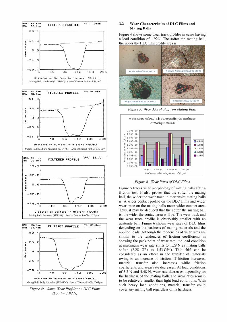
Mating Ball: Hardened (SUS440C) Area of Contact Profile: 5.54 µm2
Mating Ball: Medium Annealed (SUS440C) Area of Contact Profile: 6.19 µm2
Mating Ball: Austenite (SUS304) Area of Contact Profile: 5.27 µm2
Mating Ball: Fully Annealed (SUS440C) Area of Contact Profile: 7.64?µm2
Figure 4: Some Wear Profiles on DLC Films (Load = 1.92 N)
3.2 Wear Characteristics of DLC Films and Mating Balls
Figure 4 shows some wear track profiles in cases having a load condition of 1.92N. The softer the mating ball, the wider the DLC film profile area is.
Hardened Ball(SUS440C) M edium Annealed Ball(SUS440C)
Austenite Ball(SUS440C)Fully Annealed Ball(SUS440C)
Hardened Ball(SUS440C) M edium Annealed Ball(SUS440C)
Austenite Ball(SUS440C)Fully Annealed Ball(SUS440C)
Figure 5: Wear Morphology on Mating Balls
W ear Rates of DLC Films Depending on Hardness
of Mating Materials
0.00E+002.00E-114.00E-116.00E-118.00E-111.00E-10
1.20E-101.40E-101.60E-101.80E-102.00E-10
7.08(M ) 4.68(M ) 2.28(M )) 1.53(A)
Hardness of M ating M aterial(Gpa)
Wear Rate (mm
3/m
N)
0.64N1.28N1.92N3.20N4.48N
Figure 6: Wear Rates of DLC Films
Figure 5 traces wear morphology of mating balls after a friction test. It also proves that the softer the mating ball, the wider the wear trace in martensite mating balls is. A wider contact profile on the DLC films and wider wear trace on the mating balls mean wider contact area. Thus, it may be deduced that the softer the mating ball is, the wider the contact area will be. The wear track and the wear trace profile is observably smaller with an austenite ball. Figure 6 shows wear rates of DLC films depending on the hardness of mating materials and the applied loads. Although the tendencies of wear rates are similar to the tendencies of friction coefficients in showing the peak point of wear rate, the load condition at maximum wear rate shifts to 1.28 N as mating balls soften (2.28 GPa to 1.53 GPa). This shift can be considered as an effect in the transfer of materials owing to an increase of friction. If friction increases, material transfer also increases while friction coefficients and wear rate decreases. At load conditions of 3.2 N and 4.48 N, wear rate decreases depending on the hardness of the mating balls and wear rates remain to be relatively smaller than light load conditions. With such heavy load conditions, material transfer could cover any mating ball regardless of its hardness.

3.3 Transferred Material and Raman Spectra Analysis
Figure 7 shows the transferred materials on mating balls. At the end of the experiment, the contact surface of mating balls was fully covered with transferred materials from the DLC film. In this figure, the covered material is striped for observing purpose. As shown in the figure, the DLC film and mating ball do not actually touch as transferred materials are inter-laid between them. Figure 8 shows the Raman Spectra analysis of transferred materials on mating balls. The first peak to be analysed was designated as SP3 carbon according to the reference spectrum table [13]. The second was SP² carbon. Transferred materials on mating balls that were shifted in the second peak proved to be graphite. Therefore, it may be concluded that the transferred material is graphite and that the contact surface of a DLC film is considered to have undertaken a phase transition from carbon to graphite.
LOAD: 1.92N Ball Type: Fully Annealed Ball Magnification: X500
Transferred Material from DLC
Scratched Ball Surface
Figure 7: Transferred Material on Mating Ball
Lam an Analysis
0
50
100
150
200
250
300
350
1000 1200 1400 1600 1800
Frequency
Intensity
DLC
Fully Hardened
M edium Annealed
Fully Annealed
Austenite
Graphite
SP2 Carbon
SP3 CarbonLam an Analysis
0
50
100
150
200
250
300
350
1000 1200 1400 1600 1800
Frequency
Intensity
DLC
Fully Hardened
M edium Annealed
Fully Annealed
Austenite
Lam an Analysis
0
50
100
150
200
250
300
350
1000 1200 1400 1600 1800
Frequency
Intensity
DLC
Fully Hardened
M edium Annealed
Fully Annealed
Austenite
Graphite
SP2 Carbon
SP3 Carbon
Wave Number (cm-1)
Raman Spectra Analysis
Figure 8: Raman Spectra Analysis (Load=1.92N)
4 CONCLUSIONS Based on our study of the tribological properties of DLC films considering a mating ball’s hardness and applied loads, we conclude the following:
(1) In using martensite-mating balls, softer mating material results in higher friction coefficient because the contact area is enlarged during friction experiments.
(2) Below a load condition of 1.92N, an increase in the contact area significantly affects the friction coefficient.
(3) Above a load condition of 1.92N, however, material transfer from the DLC to the mating ball is a dominant factor that reduces friction coefficients.
(4) As the load increase, area of wear trace on mating ball widens.
(5) The load condition, which occurs maximum wear rate, shifts to 1.28N as mating ball soften.
(6) With heavy load conditions, material transfer affects all mating balls regardless of hardness.
(7) Upon close observation, the DLC film and the mating ball do not actually touch because of the inter-laying transferred materials between them.
(8) The Raman Spectra analysis proves that the transferred material is graphite and that the contact surface of DLC film undergoes a phase transition from carbon to graphite.
5 REFERENCES [1] B. Bhushan, B.K Gupta: Handbook of Tribology, McGraw-Hill, New York, (1991). [2] S. Miyake, R.Kaneko: Thin Solid Films 212 (1992) 256 [3] B.K.Gupta, B.Bhushan: Wear 190 (1995) 110. [4] A. Tanaka, M.W. Ko, S.Y. Kim, S.H. Lee and T. Kumagai : Diamond Films and Technology, 8 (1998) 1, 51-64 [5] H. Liu, A. Tanaka and, K. Umeda: The tribological characteristics of diamond-like carbon films at elevated temperatures, Thin Solid Films 346 (1999) 162-168 [6] A. Tanaka, S. Ogura and R. Murata: Friction and wear of plastics sliding against diamond-like carbon films, Proceedings of ASIATRIB ’98, 569-573. [7] H. Liu, A. Tanaka and T. Kumagai: Influence of sliding mating materials on the tribological behavior of diamond-like carbon films, Thin Solid Films, 352(1999), 145-150. [8] A. Erdemier, C. Bindal, G.R. Fenske, C. Zuiker, P. Wilbur: Surface Coating Technology, 86-87 (1996) 692. [9] K. Jia, Y.Q. Li, T.E. Fischer, B. Gallois: J. Mater. Res. 10 (1995) 1403 [10] X.M. He, W.Z. Li, H.D. Li., Surface Coating Technology, 71 (3) (1995) 223 [11] E.I. Meletis, A. Erdemir, G.R. Fenske, Surface Coating Technology, 63 (1-2) (1995) 39 [12] T. Le Huu, H.Zaidi, D. Paulmier, P. Voumard, Thid Solid Films 290-291 (1996) 126. [13] P. K. Bachmann and R. Messier, Chem. Eng. News, (1989), 24


![Effect of temperature and mating pair on tribological …...reaction to improve friction and wear behavior [11, 12]. Numerous studies have been conducted on the synergistic effect](https://static.fdocuments.net/doc/165x107/60c5168adfc5c57ff617d2f4/effect-of-temperature-and-mating-pair-on-tribological-reaction-to-improve-friction.jpg)