[email protected] Paper 56 Tel: 571-272-7822 Entered ... · PDF fileIPR2014-01198 Patent...
49
[email protected] Paper 56 Tel: 571-272-7822 Entered: February 3, 2016 UNITED STATES PATENT AND TRADEMARK OFFICE _______________ BEFORE THE PATENT TRIAL AND APPEAL BOARD _______________ HTC CORPORATION and HTC AMERICA, INC., Petitioner, v. NFC TECHNOLOGY, LLC, Patent Owner. _______________ Case IPR2014-01198 Patent 6,700,551 B2 _______________ Before JAMES B. ARPIN, NEIL T. POWELL, and BART A. GERSTENBLITH, Administrative Patent Judges. ARPIN, Administrative Patent Judge. FINAL WRITTEN DECISION 35 U.S.C. § 318(a) and 37 C.F.R. § 42.73
Transcript of [email protected] Paper 56 Tel: 571-272-7822 Entered ... · PDF fileIPR2014-01198 Patent...

[email protected] Paper 56 Tel: 571-272-7822 Entered: February 3, 2016
UNITED STATES PATENT AND TRADEMARK OFFICE _______________
BEFORE THE PATENT TRIAL AND APPEAL BOARD
_______________
HTC CORPORATION and HTC AMERICA, INC., Petitioner,
v.
NFC TECHNOLOGY, LLC, Patent Owner.
_______________
Case IPR2014-01198 Patent 6,700,551 B2 _______________
Before JAMES B. ARPIN, NEIL T. POWELL, and BART A. GERSTENBLITH, Administrative Patent Judges. ARPIN, Administrative Patent Judge.
FINAL WRITTEN DECISION 35 U.S.C. § 318(a) and 37 C.F.R. § 42.73

IPR2014-01198 Patent 6,700,551 B2
2
I. INTRODUCTION
A. Background
HTC Corporation and HTC America, Inc. (collectively, “Petitioner”)
filed a Petition (Paper 1, “Pet.”) to institute an inter partes review of
claims 1–3 and 5 of Patent No. US 6,700,551 B2 (Ex. 1001, “the ’551
patent”) pursuant to 35 U.S.C. §§ 311–319. Pet. 1. NFC Technology, LLC
(“Patent Owner”) filed a Preliminary Response. Paper 9 (“Prelim. Resp.”).
On February 4, 2015, we issued a Decision on Institution (Paper 10, “Dec.
on Inst.”), instituting inter partes review of claims 1–3 and 5 of the ’551
patent (“the challenged claims”). Dec. on Inst. 17–18. Subsequent to
institution, Patent Owner filed a Patent Owner Response (Paper 18, “PO
Resp.”), Petitioner filed a Reply (Paper 42, “Pet. Reply”) thereto, and Patent
Owner filed a Sur-Reply (Paper 50, “PO Sur-Reply”). Further, Patent
Owner filed a Motion for Observations on Cross-Examination of Petitioner’s
declarant, Dr. Emmanouil Tentzeris (Paper 47), and Petitioner filed a
Response to Patent Owner’s Motion for Observations (Paper 52).
The parties requested an oral hearing (Paper 46; Paper 48) and
appeared before us on December 18, 2015. The record includes a transcript
of the oral hearing. Paper 55 (“Tr.”).
We have jurisdiction under 35 U.S.C. § 6(c). This Final Written
Decision, issued pursuant to 35 U.S.C. § 318(a) and 37 C.F.R. § 42.73,
addresses issues and evidence raised during the inter partes review. For the
reasons that follow, Petitioner demonstrates by a preponderance of the
evidence that claims 1–3 and 5 of the ’551 patent are unpatentable.

IPR2014-01198 Patent 6,700,551 B2
3
B. Related Proceedings
Petitioner indicates that the ’551 patent is the subject of the following
co-pending U.S. district court case: NFC Technology LLC v. HTC Corp.,
No. 2:13-cv-1058 (E.D. Tex.), filed December 5, 2013. Pet. 1. In addition,
at the request of Petitioner, we instituted an inter partes review, IPR2014-
01199, with respect to a related patent, Patent No. US 7,665,664 B2, against
Patent Owner. HTC Corp. v. NFC Tech., LLC, Case IPR2014-01199, slip
op. at 3, 17 (PTAB Feb. 4, 2015) (Paper 10).
C. The ’551 Patent
The ’551 patent generally relates to methods and apparatus designed
to wirelessly exchange data through inductive coupling, e.g., by radio-
frequency identification (“RFID”) devices. Ex. 1001, col. 1, ll. 9–18. In
particular, the ’551 patent relates to “portable electronic objects comprising
a contactless integrated circuit, such as contactless smart card readers,
electronic label scanners, electronic badge scanners,” and the like. Id. at
col. 1, ll. 15–18. Specifically, “one object of the present invention is to
provide a data transmission device of the type described above that can
modulate the antenna signal with a modulation depth of less than 100%
while being simple in structure and inexpensive to produce.” Id. at col. 1,
ll. 61–65.

IPR2014-01198 Patent 6,700,551 B2
4
Figure 3 of the ’551 patent is reproduced below:
Figure 3 depicts an embodiment of the invention, in which microprocessor 2
employs a plurality of binary ports P1–P4 to produce the modulated antenna
signal. See id. at col. 5, ll. 34–37. As explained in the Specification,
“microprocessor 2 comprises binary ports P1 to P7 that can be set to ‘1’
(voltage VDD), to ‘0’ (output of the port to the ground) or to high
impedance state.” Id. at col. 3, ll. 32–34. In the embodiment of Figure 3,
selected binary ports, e.g., ports P1–P4, are used to “deliver a power supply
signal Sp which is the combination of signals Sp1, Sp2, Sp3, Sp4 delivered
by each of the ports, and which is applied to the antenna circuit 10 by means
of the inductor 13 and the capacitor 14 described above.” Id. at col. 3,
ll. 43–46. In the depicted embodiment, “the modulation of the antenna
signal Sa is obtained by setting all the ports P1 to P4 to 0 or by setting
certain ports to high impedance while the other ports are maintained on 1.”
Id. at col. 4, ll. 21–24. Thus, “setting all the ports P1 to P4 to 0” results in
“the power supply signal Sp [being] zero and the amplitude of the antenna
signal Sa [being] modulated at 100% (standard ISO/A).” Id. at col. 4, ll. 21–

IPR2014-01198 Patent 6,700,551 B2
5
26. Modulation of the amplitude of antenna signal Sa at less than 100% may
be achieved by “setting certain ports to high impedance while the other ports
are maintained on 1” in order to permit “a more substantial current [to]
pass[] through the ports maintained on 1 and their internal resistor Ri [to]
cause[] the voltage of the power supply signal Sp to drop without cancelling
it.” Id. at col. 4, ll. 21–31. Modulation switch 4 “is controlled by the signal
S1 and does not receive an amplitude modulation signal delivered by the
microprocessor, as was the case in previous practices.” Id. at col. 3, ll. 49–
52; cf. id. at Figs. 1, 2.
Although the embodiment of Figure 3 employs microprocessor 2, any
type of control circuit providing features, such as those described above,
may be used to achieve the disclosed methods and apparatus. Id. at col. 5,
ll. 34–37. In particular, the ’551 patent explains that the modulation may be
controlled by binary ports that are a part of many off-the-shelf chips and are
“simple in structure and inexpensive to produce.” Id. at col. 1, ll. 64–65.
Suitable integrated circuits “can include a microprocessor or a
programmable logic circuit comprising ‘port’ type switch lines with a
structure that is equivalent to that of a microprocessor port.” Id. at col. 5,
ll. 39–43.
D. Illustrative Claim
Petitioner challenges method claims 1–3 and apparatus claim 5 of the
’551 patent. Pet. 3. Claim 1 is independent. Ex. 1001, col. 7, ll. 16–29.
Each of claims 2, 3, and 5 depends directly from claim 1. Claim 1 of the
’551 patent is illustrative of the claims at issue and is reproduced below:
1. Method for modulating the amplitude of the antenna signal of an inductive antenna circuit comprising a coil, by means of a control circuit comprising binary ports that can be
IPR2014-01198 Patent 6,700,551 B2
6
set to high impedance state and with a non-zero internal resistor, characterised [sic] in that the antenna circuit is electrically powered by at least two ports of the control circuit, and in that it comprises steps of:
setting the ports providing the electric supply of the antenna circuit to “1”, to supply the antenna circuit at full power level, and
changing the state of at least one of the ports providing the electric supply of the antenna circuit, to modulate the amplitude of the antenna signal.
Ex. 1001, col. 7, ll. 16–28 (emphases added).
E. Relied Upon References, Document, and Declarations
Petitioner relies upon the following references, document, and
declaration in challenging the identified claims of the ’551 patent:
Exhibit No. References, Document, and Declaration
1002 Prosecution File History for the ’551 Patent (U.S. Patent Application No. 09/962,889)
1003 Declaration of Dr. Emmanouil Tentzeris
1004 Patent No. US 6,122,492 to Sears (“Sears”)
1005 Patent No. US 5,399,925 to Nguyen (“Nguyen”)
1031 Rebuttal Declaration of Dr. Emmanouil Tentzeris
F. Grounds Under Review
Petitioner asserts that the challenged claims are unpatentable under
35 U.S.C. § 103(a) on the following specific grounds (Pet. 3–4, 11–60):
Ground Reference(s) Challenged Claims
35 U.S.C. § 103(a) Sears 1–3 and 5
35 U.S.C. § 103(a) Sears and Nguyen 1–3 and 5

IPR2014-01198 Patent 6,700,551 B2
7
II. ANALYSIS
A. Claim Construction
Consistent with the statute and the legislative history of the America
Invents Act (“AIA”), we interpret claims of an unexpired patent using the
broadest reasonable construction in light of the specification of the
patent. Pet. 8; see Office Patent Trial Practice Guide, 77 Fed. Reg. 48,756,
48,766 (Aug. 14, 2012) (Claim Construction); 37 C.F.R.
§ 42.100(b).1 Under the broadest reasonable construction standard, a claim
term is presumed to have an ordinary and customary meaning as would have
been understood by one of ordinary skill in the art in the context of the entire
disclosure. In re Translogic Tech., Inc., 504 F.3d 1249, 1257 (Fed. Cir.
2007). A patentee may act as his or her own lexicographer by providing a
special definition for a claim term in the specification with “reasonable
clarity, deliberateness, and precision.” In re Paulsen, 30 F.3d 1475, 1480
(Fed. Cir. 1994). Generally, in the absence of such a special definition or
other considerations, “limitations are not to be read into the claims from the
specification.” In re Van Geuns, 988 F.2d 1181, 1184 (Fed. Cir. 1993).
1. Confirmation of Previous Constructions
In its Petition, Petitioner proposed constructions for the following
claim terms: (1) “binary ports that can be set to high impedance states”
(Claim 1), (2) “high impedance state” (Claim 3), (3) “non-zero internal
resistor” (Claim 1), (4) “full power level” (Claim 1), and (5) “100%
1 In re Cuozzo Speed Techs. LLC, 793 F.3d 1268, 1277 (“Congress implicitly approved the broadest reasonable interpretation standard in enacting the AIA”), 1279 (“the standard was properly adopted by PTO regulation.”) (Fed. Cir. 2015), cert. granted sub nom. Cuozzo Speed Techs. LLC v. Lee, 84 U.S.L.W. 3218 (Jan. 15, 2016) (No. 15-446).

IPR2014-01198 Patent 6,700,551 B2
8
modulation” (Claim 2). Pet. 9–11. We construed each of these terms for
purposes of our Decision on Institution. Dec. on Inst. 6–10. Patent Owner
does not contest those constructions in its Patent Owner Response. PO
Resp. 8; see Paper 11, 2–3 (“The patent owner is cautioned that any
arguments for patentability not raised in the response will be deemed
waived.”). Consequently, we now confirm our constructions of those claim
terms, as follows:
a. “binary ports that can be set to high impedance state” (Claim 1)
“binary ports that can be set to high impedance state” means “a port or
other portion of a circuit that can be set to binary logic ‘1,’ binary logic ‘0,’
or high impedance state” (Dec. on Inst. 8);
b. “high impedance state” (Claim 3)
“high impedance state” means “a state of a portion of a circuit when
the portion is not driven to either the ‘0’ (connection to ground) or ‘1’
(connection to Vdd) states and the resistance of the port approaches or
equals that of an open-circuit state” (id. at 9);
c. “non-zero internal resistor” (Claim 1)
“non-zero internal resistor” means “a component in the portion of the
circuit that has a resistance above zero” (id. at 9–10);
d. “full power level” (Claim 1)
“full power level” means “setting the ports providing the electric
supply of the antenna circuit to ‘1’ to supply the antenna circuit at full power
level” (id. at 10–11); and
e. “100% modulation” (Claim 3)
“100% modulation” means “reduction of the amplitude of the antenna
signal from its maximum value nominally to zero” (id. at 11).

IPR2014-01198 Patent 6,700,551 B2
9
2. Additional Constructions Proposed in Patent Owner Response
In the Patent Owner Response, Patent Owner proposes constructions
for additional terms: (1) “setting the ports providing the electric supply of
the antenna circuit to ‘1’” (Claim 1) and (2) “set to ‘0’” (Claim 2). PO
Resp. 8–9. In particular, Patent Owner contends that “a person of ordinary
skill in the art would understand that setting to ‘1’ or ‘0’ means placing the
port into one of two states (Ex. 2027, Apsel Dec., ¶ 36.)” PO Resp. 9.
Petitioner argues that Patent Owner’s proposed constructions improperly
seek to incorporate a “setting individual ports” requirement into claim 1.
Pet. Reply 3.
Claim 1 recites that “the antenna circuit is electrically powered by at
least two ports of the control circuit” and the step of “setting the ports
providing the electric supply of the antenna circuit to ‘1’.” Ex. 1001, col. 7,
ll. 20–25 (emphases added). Similarly, claim 2 recites “the ports providing
the electric power supply of the antenna circuit are set to ‘0’.” Id. at col. 7,
ll. 29–31 (emphases added). We agree with Petitioner that the meaning of
this claim language is that the “at least two ports” supplying electric power
to the antenna circuit are both (or all) set to “1” or “0.” While the steps of
claims 1 and 2 may permit individually setting the ports (Ex. 2027 ¶ 36), the
claim language makes clear that, in order to satisfy the claim language, all of
the “at least two ports” supplying electric power of the antenna circuit must
be set to “1” or “0.”
Further, claim 1 recites the step of “changing the state of at least one
of the ports providing the electric supply of the antenna circuit, to modulate
the amplitude of the antenna signal.” Ex. 1001, col. 7, ll. 26–28 (emphasis
added). Thus, the claim terms considered in the context of the language of

IPR2014-01198 Patent 6,700,551 B2
10
claim 1, as a whole, make clear that the “setting” step applies to the “at least
two ports” and the “changing” step applies to “at least one of the ports.”
(Emphases added).
“In claim construction, [the Federal Circuit] gives primacy to the
language of the claims, followed by the specification.” Tempo Lighting Inc.
v. Tivoli LLC, 742 F.3d 973, 977 (Fed. Cir. 2014) (citing In re Morris,
127 F.3d 1048, 1056 (Fed. Cir. 1997)). The Specification of the ’551 patent
makes clear that “this 100% modulation is ‘obtained by simultaneously
setting ports P1 to P4 to 0 (signals SP1 to SP4 to 0).’” PO Resp. 8 (quoting
Ex. 1001, col. 5, ll. 5–8); see also Ex. 1001, col. 3, ll. 54–57 (“According to
the method of the present invention, the four ports P1 to P4 are maintained
on state ‘1’ (voltage VDD present on the ports) to supply the antenna circuit
10 at full power level” (emphasis added)).
Therefore, the broadest reasonable interpretation of the term “setting
the ports providing the electric supply of the antenna circuit to ‘1’”
(Claim 1) is “setting two or more of the at least two ports supplying electric
power to the antenna circuit to ‘1’” and of the term “set to ‘0’” (Claim 2) is
to “set two or more of the at least two ports supplying electric power to the
antenna circuit to ‘0’.”2 See Ex. 1031 ¶ 36.
3. Other Claim Terms
Neither party offers constructions of other terms in the challenged
claims. See Pet. 9–11; PO Resp. 8–9. Only terms that are in controversy in
2 Patent Owner does not base its constructions in the prosecution history of the ’551 patent (see Ex. 1002), but does rely on a declarant’s testimony as to the meaning of these terms to a person of skill in the art (Ex. 2027). On this record, the construction of these terms would not differ under the Phillips standard. Phillips v. AWH Corp., 415 F.3d 1303 (Fed. Cir. 2005) (en banc).

IPR2014-01198 Patent 6,700,551 B2
11
this proceeding need to be construed, and then only to the extent necessary
to resolve the controversy. Vivid Techs., Inc. v. Am. Sci. & Eng’g, Inc.,
200 F.3d 795, 803 (Fed. Cir. 1999). Therefore, no other claim terms require
express construction.
B. Antedating Sears
Petitioner argues that claims 1–3 and 5 of the ’551 patent would have
been rendered obvious over Sears and over Sears and Nguyen. Pet. 3. We
instituted inter partes review on those grounds. See supra Section I.F; Dec.
on Inst. 17–18. Initially, Patent Owner contends that Sears does not
constitute prior art under 35 U.S.C. § 102(e), as Petitioner alleges. PO
Resp. 9; see Pet. 3. For the reasons set forth below, we are not persuaded
that the inventor’s testimony is corroborated adequately, and we determine
that Patent Owner has not met its burden of producing sufficient evidence
that the subject matter of the challenged claims was invented prior to
February 8, 1999, the filing date of Sears.
1. Background
a. Patent Owner’s Contentions
As noted above, Patent Owner contends that Sears does not constitute
prior art to the challenged claims of the ’551 patent under 35 U.S.C.
§ 102(e), as Petitioner alleges. PO Resp. 9–34. The French patent
application, from which the ’551 patent claims the benefit, was filed on
March 25, 1999 (id. at 1–2; Pet. 3; Ex. 1001, (30) (63)); and the U.S. patent
application that eventually issued as Sears was filed on February 8, 1999
(PO Resp. 9; Pet. 3; Ex. 1004, (22)). Patent Owner contends that the subject
matter recited in the challenged claims of the ’551 patent was “actually
reduced to practice on or before November 1998,” i.e., before February 8,

IPR2014-01198 Patent 6,700,551 B2
12
1999. PO Resp. 9. In support of this contention, Patent Owner provides
declarations of: the sole named inventor, Bruno Charrat, Chief Operating
Officer at b-pack (Ex. 2023); as well as André Marchand, a patent attorney
at Omnipat in Aix-en-Provence, France (Ex. 2024); and Francois Lepron, an
engineer at INSIDE Technologies (“INSIDE”) at the time of the alleged
actual reduction of the subject matter of the challenged claims to practice
(Ex. 2025 (expunged)). Although Mr. Lepron executed a declaration in
support of Patent Owner’s contentions regarding the actual reduction to
practice of the recited subject matter, Mr. Lepron refused “for personal
reasons” to be deposed by Petitioner. Ex. 1023 (English translation of
e-mail from Mr. Lepron to Murielle Greusard, France Brevets).
Consequently, we authorized Petitioner to file a Motion to Strike
Mr. Lepron’s declaration (Paper 38), which Petitioner did (Paper 39), and,
after considering Patent Owner’s Opposition to the Motion to Strike
(Paper 40), granted Petitioner’s Motion (Paper 41) and expunged
Mr. Lepron’s declaration (Ex. 2025). See Office Patent Trial Practice Guide,
77 Fed. Reg. 48,756, 48,761 (Aug. 14, 2012); 37 C.F.R. §§ 41.51(b),
42.53(g). As a result, Mr. Lepron’s declaration is no longer part of the
record in this proceeding, and “to the extent that Patent Owner relies on
Exhibit 2025, wholly or in part, as evidence to support argument in the
Patent Owner Response, we give no weight to that reliance on expunged
Exhibit 2025.” Paper 41, 5.
i. Conception by Mr. Charrat
Patent Owner contends that Mr. Charrat conceived of the subject
matter recited in the challenged claims on or before September 10, 1998.
PO Resp. 16. Specifically, Patent Owner contends that, in mid-1998,

IPR2014-01198 Patent 6,700,551 B2
13
“engineers at a company called INSIDE Technologies (later renamed
INSIDE Contactless and then renamed as INSIDE Secure) began work on
what the company called M210H.”3 Id. at 11–12 (emphasis added). This
device was to be “compatible with both of the ISO/A and ISO/B standards,
yet having fewer components than the previous INSIDE devices.” Id. at 12.
In particular, the ISO/A standard requires the modulation of a transmission
signal by 100%, and the ISO/B standard requires the modulation of a
transmission signal by only 10%. Id. (citing Ex. 2026, 4, 8). The M210H
was required to operate in accordance with either standard. Id. (citing
Ex. 2023 ¶ 23).
According to Patent Owner,
Mr. Charrat provided that solution in September of 1998 when he conceived of using available tri-state binary ports of an off-the-shelf microprocessor to achieve the variable modulation. ([Ex. 2023] ¶¶ 25–26.) Specifically, by September 10, Mr. Charrat had fully worked out how to implement the design of the M210H using only available microprocessor ports (as opposed to a separate modulation circuit) to modulate the carrier signal. (Id. at ¶ 34.) Indeed, he had already begun the process of implementing the device as hand-drawn layouts in his notebook at that time show.
PO Resp. 13.
In support of its contention that Mr. Charrat conceived of the recited
subject matter of the challenged claims, Patent Owner relies primarily on
3 Patent Owner contends that “[a]ll of the development of the M210H device occurred in Aix-en-Provence, France, which is a WTO country. Accordingly, the inventor is entitled to the same priority rights ‘as if such invention had been made in the United States.’” PO Resp. 12 n.2 (quoting 35 U.S.C. § 104(a)(C)(2) (pre-AIA)). Petitioner does not contest the contention.

IPR2014-01198 Patent 6,700,551 B2
14
two pieces of evidence, in addition to Mr. Charrat’s testimony (Ex. 2023).
First, Patent Owner relies on excerpts from Mr. Charrat’s laboratory
notebook. PO Resp. 13–14 (reproducing Figure 3 of Ex. 2006). Although
some of the laboratory notebook pages are dated, the laboratory notebooks
are neither signed by Mr. Charrat nor witnessed by another person.
Tr. 39:20–40:7 (“The notebooks are not signed by anyone. These are not
notebooks that are maintained in the same sense as an inventor’s lab
notebook would be maintained in accordance with United States law.”); see
id. at 49:14–20. Moreover, the notebook excerpts reproduced in
Exhibits 2004–2006 do not appear to be the original notebooks’ pages, but,
instead, appear to be reproductions of pages annotated by Patent Owner to
include certified translations of the French text from the notebooks. E.g.,
Ex. 2004, 4 (certification of translation); see Ex. 2030 ¶ 2. Second, Patent
Owner relies on “a high-level block diagram of the M210H showing a
processor directly connected to an emitter, which is itself connected to an
antenna.” PO Resp. 15 (citing Ex. 2001, Fig. 4). Patent Owner contends
that “Mr. Charrat began his efforts to design the M210H project on or before
June 26, 1998, when he drafted an initial project data sheet memorializing
the requirements of the M210H device. (See, Ex. 2001, p. 2.)” PO Resp. 14.
Referring to Exhibit 2001, Mr. Charrat testifies that
This project to develop a microcontroller-based modulation (the project that would ultimately be described in the ‘551 patent) began on or before June 26, 1998, when I produced an initial project data sheet detailing the requirements for a project that was, at the time, called Readcrypt M210H. A subsequent version of this document dated July 21, 2007,[4] is attached as Ex. 2001 and details various features of the M210H project.
4 Mr. Charrat testifies that data sheet that “evolved” into Exhibit 2001,

IPR2014-01198 Patent 6,700,551 B2
15
Ex. 2023 ¶ 28 (emphasis added). There is no author named on this datasheet
(Ex. 2001), and only Patent Owner’s argument and Mr. Charrat’s own
testimony asserts that Mr. Charrat is the author of the data sheet.
After the initial data sheet for the M210H device was prepared on
June 28, 1998, Patent Owner contends that
Mr. Charrat and others generated a product development request (PDR). Like the data sheet, the PDR outlined general requirements for the M210H device, which included a requirement for compatibility with both the ISO/A and ISO/B standards. (Ex. 2023, Charrat Dec., ¶ 30; Ex. 2002.) Another contemporaneous internal document from INSIDE also lays out the requirement that the M210H low-cost reader would need to “read ISO A & B chips.” ([Ex. 2023] ¶ 31; Ex. 2003, p. 5.)
PO Resp. 15–16 (emphases added). Neither Patent Owner nor Mr. Charrat
contends that Mr. Charrat alone produced either Exhibit 2002 or
Exhibit 2003, and again neither exhibit identifies its author. Nevertheless,
Mr. Charrat testifies that, after the requirements for the M210H device had
been identified, he continued to work on the design of the device, and “[b]y
September 10, 1998, [he] had fully conceived of the idea of using a
PIC16C63 microprocessor to power and control the modulation of the
antenna.” PO Resp. 16 (citing Ex. 2023 ¶ 34).
ii. Actual Reduction to Practice by the INSIDE Team
After the design for the M210H device had been created, Patent
Owner contends that Mr. Charrat worked with his development team at
INSIDE, consisting of Mr. Charrat, Mr. Lepron, Alban de Moncuit, and
which originally was created on July 21, 1998, but that Exhibit 2001 is properly dated “July 21, 2007,” more than eight (8) years after Sears’s filing date. Ex. 2023 ¶ 28 n.3.

IPR2014-01198 Patent 6,700,551 B2
16
Rodrigue Gil, to construct a working prototype. Id. (citing Ex. 2023 ¶ 13).
In September of 1998, Mr. Charrat contends that the development of the
M210H device was sufficient, such that “INSIDE commissioned a company
called Concept Electronique to generate printed circuit board (PCB) layouts
for the prototype M210H device. (Ex. 2023, Charrat Dec., ¶¶ 36–38.)
Concept Electronique generated the PCB layout and sent it to INSIDE for
approval.” PO Resp. 17. The PCB layouts generated by Concept
Electronique are depicted in Exhibit 2007. See PO Resp. 17–18
(reproducing figures from Ex. 2007, 4–9).
Patent Owner contends that, on September 10, 1998, Mr. Charrat
instructed Concept Electronique to fabricate a prototype of the M210H
device. Ex. 2009 (return of facsimile cover sheet stating “OK FAB” signed
by Mr. Charrat and dated “10/09/98”); see Tr. 33:20–34:6. Patent Owner
acknowledges, however, that it does not have direct evidence showing what
the INSIDE team of engineers sent to Concept Electronique or what was
contained in the four (4) pages Concept Electronique sent to the INSIDE
team as an attachment to the facsimile cover sheet. See Tr. 34:7–13.
Nevertheless, Patent Owner contends that the prototype, which was
fabricated by Concept Electronique, was tested by the INSIDE team and
performed according to the recited limitations of the challenged claims. PO
Resp. 19–21. In November of 1998, Mr. de Moncuit allegedly prepared a
report (Ex. 2012) indicating that the Concept Electronique prototype device
was capable of both 100% modulation and 10% modulation and “worked for
its intended purpose of being compatible with both the ISO/A and ISO/B
standards.” Id. at 20–21 (citing Ex. 2023 ¶ 45); see Ex. 2012, 7 (depicting

IPR2014-01198 Patent 6,700,551 B2
17
test results for 100% modulation), 8 (depicting test results for 10%
modulation). Exhibit 2012 does not name its author.
Although Exhibits 2007 and 2009 refer to the “M210H” device
(Ex. 2007, 1–3, 6, 8–12; Ex. 2009, 1, 3) and Patent Owner contends that this
reference to the “M210H” device links these two documents (Tr. 35:14–
36:20), Exhibit 2012 refers to the “M210H-2” device, rather than the
“M210H” device (Ex. 2012, 3; see Tr. 22:17–23:10). During his deposition,
Mr. Charrat was unable to explain what the “M210H-2” device was or how
it differed from the “M210H” device. Ex. 1026, 32:17–33:3; see Tr. 48:13–
24. Further, Patent Owner contends that the INSIDE team verified that the
Concept Electronique prototype conformed to their design. PO Resp. 21–22
(reproducing the highlighted wiring diagram of Ex. 2013). The legend of
Exhibit 2013 is reproduced below:
Ex. 2013, 1. As shown in the reproduced portion, Exhibit 2013 is identified
as “Revision: 3” and is dated “Feb 05, 1999,” over two months after Mr. de
Moncuit prepared his report on the M210H-2 device manufactured by
Concept Electronique. Id.; see Ex. 2012, 1.
Patent Owner contends that, on January 15, 1999, Mr. Charrat met
with his attorney, Mr. Marchand, to discuss the preparation of a patent
application claiming the invention corresponding to the Concept
Electronique prototype. PO Resp. 22–26. Mr. Marchand testifies that
Mr. Charrat explained to me that the M210H device operated at 13.56 MHz using a large coil (i.e., inductive antenna) connected to the reader. (Ex. 2015, p. 1.) Furthermore, Mr. Charrat’s

IPR2014-01198 Patent 6,700,551 B2
18
prototype device used a commercially available microcontroller (i.e., the PIC16C63 in this case) to power the antenna. (Ex. 2016, p. 1.) Additionally, my notes (Ex. 2015) reflect that Mr. Charrat explained to me that the device connected multiple ports (5 indicated in these notes), which allowed the transmitter to employ either of the ISO/A (100% modulation) or the ISO/B (i.e., 10% modulation) standards. (Id., p. 4.)
Ex. 2024 ¶ 8 (emphases added); see Ex. 1032 ¶¶ 3, 4. In particular, Patent
Owner contends that,
[o]n February 24, 1999, Mr. Marchand sent Mr. Charrat a first draft of the patent application containing the description of the M210H prototype device. . . . After some minor corrections to the first draft, a second draft was sent to Mr. Charrat and the application was filed on March 25, 1999. . . . This application described the M210H prototype that Mr. Charrat had designed, built, and tested in November 1998.
PO Resp. 25–26 (emphases added) (citing Ex. 2023 ¶¶ 55–57; Ex. 2024
¶¶ 11, 13–15). Thus, Mr. Marchand drafted an application based on
Mr. Charrat’s description of the Concept Electronique prototype that
allegedly embodies Mr. Charrat’s invention, as described to Mr. Marchand,
but Mr. Marchand admitted that he has no personal knowledge that the
described prototype had been made or tested. Ex. 1024, 26:25–27:14.
Finally, Patent Owner contends that the Concept Electronique
prototype satisfies all of the limitations of claims 1–3 and 5 of the
’551 patent. PO Resp. 26–33. Accordingly, in view of the arguments and
evidence presented in Patent Owner’s Response (id. at 11–34), Patent Owner
contends that it has met “its burden, under at least a preponderance of the
evidence, to show an actual reduction to practice of the claimed subject
matter prior to the effective prior art date of the Sears reference” (id. at 34).

IPR2014-01198 Patent 6,700,551 B2
19
b. Petitioner’s Reply
Petitioner responds that Patent Owner’s evidence allegedly showing
the fabrication, testing, and verification of the Concept Electronique
prototype “lack[s] independent corroboration because they are authenticated
and corroborated solely by the inventor himself.” Pet. Reply 10–12. In
particular, Petitioner argues that the evidence that Patent Owner primarily
relies upon in support of its contentions, namely, the PCB Layout, generated
by Concept Electronique (Ex. 2007); the facsimile cover sheet, dated
September 10, 1998 (Ex. 2009); and the test report, prepared by
Mr. de Moncuit and dated November 1998 (Ex. 2012), are corroborated only
by Mr. Charrat’s testimony. See Pet. Reply 11–12. Moreover, the other
evidence that Patent Owner relies upon in support of its contentions, namely,
materials produced by INSIDE personnel (Exs. 2001–2003) and excerpts
from Mr. Charrat’s notebooks (Exs. 2004–2006, 2010, and 2011) also are
corroborated only by Mr. Charrat’s testimony. Pet. Reply 12–13. Further,
Petitioner argues that the documents created by Mr. Marchand or his staff in
connection with the preparation of the French patent application, from which
the ’551 patent claims priority, (Exs. 2015–2022) are not properly
corroborated because of Mr. Marchand’s alleged bias. Pet. Reply 13–14.
In addition, Petitioner argues that the Concept Electronique prototype
did not work for its intended purpose because: (1) no software necessary to perform ISO/A and B modulations had been developed at the time of the Nov. 98 Tests (Ex. 1031, ¶¶120–127); (2) the hardware tested in the Nov. 98 Tests was incapable of performing these modulations (id. at ¶¶110–115); and (3) the two separate tests PO cites from the Nov. 98 Tests, at best, tested two different devices and not a single fabricated device (id. at ¶79). Because the M210H Prototype did not work,

IPR2014-01198 Patent 6,700,551 B2
20
it lacked a processor capable of powering an antenna and modulating antenna signals, as required by claims 1-3 and 5.
Pet. Reply 14. In particular, Petitioner argues that software was necessary
for the prototype to operate according to its intended purpose (Ex. 1026,
17:12–18:9), but that Mr. Lepron, the engineer tasked with developing that
software (Ex. 1026, 11:22–24), did not work on the project between
September and November of 1998, during which time the prototype was
fabricated. Pet. Reply 14–16 (citing Ex. 1031 ¶¶ 120–122, 124). Further,
Petitioner argues that, because harmonic noise also was introduced into the
prototype by its transistor 2N7002, the Concept Electronique prototype
failed to operate for its intended purpose. Id. at 16–20. Specifically, the
level of noise generated in the prototype was too high to permit the recited
modulation levels. Id. at 17. Finally, Petitioner argues that the tests
described in Exhibit 2012 rely on two separate wiring configurations and
thus do not support Patent Owner’s claim that the subject matter of the
challenged claims was actually reduced to practice. Id. at 20–22. In
particular, Petitioner argues that
[i]n one test, the ‘transmitter is supplied by 4-micro-controller ports.’ Ex. 2012, 7 (emphasis added); Ex. 1031, ¶79. In the second test, only 3 ports are used with respect to the transmitter. [Ex. 2012], 8; Ex. 1031, ¶ 79. The 4th port of the 3-port test is entirely unaccounted for.
Pet. Reply 20–21.
Petitioner argues that Patent Owner’s evidence is contradictory and
cannot support its contention that the subject matter of the challenged claims
was actually reduced to practice before the filing date of Sears. Id. at 22–25.
Because Patent Owner relies solely on actual reduction to practice to
antedate Sears, Petitioner argues that Patent Owner has failed to meet its

IPR2014-01198 Patent 6,700,551 B2
21
burden and urges that “the Board should not and need not address any
factors relating to conception or diligence.” Pet. Reply 25 (citing Scott v.
Finney, 34 F. 3d 1058, 1060 (Fed. Cir. 1994) (only addressing actual
reduction to practice because PO opted to argue it)).
c. Patent Owner’s Sur-Reply
Because Patent Owner bears the burden of production regarding
evidence supporting the antedating of Sears, we granted Patent Owner’s
request to file a Sur-Reply limited to the question of antedating. Paper 45,
3–5. Patent Owner contends that Petitioner’s arguments challenging Patent
Owner’s efforts to antedate Sears are flawed for three reasons. PO Sur-
Reply 1. First, Patent Owner contends Petitioner’s “lack-of-corroboration
arguments are legally flawed because they conflate authentication with
corroboration.” Id. at 1–3. In particular, Patent Owner contends that
“‘[c]orroboration’ deals with sufficiency of the evidence, while
‘authentication’ deals [with] its admissibility.” Id. at 1 (emphasis added).
Further, lack of authentication is an evidentiary issue properly addressed by
a motion to exclude evidence. Id. at 3. Thus, Patent Owner contends that
Mr. Charrat’s testimony is sufficiently and independently corroborated by
other pieces of documentary evidence. Id. at 3; but see In re NTP, Inc.,
654 F.3d 1279, 1293 (Fed. Cir. 2011) (rejecting the “circular logic of using
the files to corroborate the testimony and the testimony to corroborate the
files”).
Second, Patent Owner contends that Petitioner overstates what is
legally required to show actual reduction to practice. Id. at 4–5. In
particular, Patent Owner contends that, in order to show actual reduction to
practice, Patent Owner “need only show that [the] invention has been

IPR2014-01198 Patent 6,700,551 B2
22
sufficiently tested to demonstrate that it will work for its intended purpose,
but it need not be in a commercially satisfactory stage of development.” Id.
at 4; see Scott, 34 F.3d at 1062. Thus, the presence of “harmonic noise” or
other minor deficiencies in the prototype are not sufficient to prevent the
prototype from showing actual reduction to practice. Id. at 4–5 (citing
Ex. 2023 ¶¶ 44, 45); see Pet. Reply 17.
Third, Patent Owner contends that Petitioner’s rebuttal “evidence”
improperly relies on its declarant’s, Dr. Tentzeris’s, factual testimony; but
Patent Owner contends that Dr. Tentzeris has no personal knowledge of the
facts surrounding the actual reduction to practice of Mr. Charrat’s purported
invention. Id. at 5; see Paper 47, 1–6.5 Thus, Patent Owner contends that
Dr. Tentzeris’s testimony regarding the facts surrounding the actual
reduction to practice of the subject matter of the challenged claims should be
given little or no weight. Id.
2. Discussion
Petitioner bears the burden of persuasion, by a preponderance of the
evidence, that the challenged claims are unpatentable. 35 U.S.C. § 316(e).
Petitioner has proffered Sears, which presumptively constitutes prior art
under 35 U.S.C. § 102(e) because it was filed in the U.S. Patent and
Trademark Office on February 8, 1999, before the filing date, i.e., March 25,
1999, of the French parent application of the ’551 patent. This difference in
dates gives rise to Patent Owner’s burden to produce evidence supporting a
5 We do not rely on Dr. Tentzeris’s testimony regarding Exhibits 2007, 2009, and 2012, and regarding INSIDE Technologies in our analysis of Patent Owner’s contentions with respect to the antedating of Sears. See Paper 47; Paper 52.

IPR2014-01198 Patent 6,700,551 B2
23
date of invention before the Sears’s filing date, i.e., before February 8, 1999.
See Mahurkar v. C.R. Bard, Inc., 79 F.3d 1572, 1576–77 (Fed. Cir. 1996).
“To antedate . . . an invention, a party must show either an earlier
reduction to practice, or an earlier conception followed by a diligent
reduction to practice.” Purdue Pharma L.P. v. Boehringer Ingelheim
GMBH, 237 F.3d 1359, 1365 (Fed. Cir. 2001) (emphasis added, internal
citation omitted). Patent Owner’s position is based on the first of these
options, i.e., that it was the first actually to reduce the invention to practice,
rather than the first to conceive plus diligent reduction to practice. PO
Resp. 9; PO Sur-Reply 4–5.
A party seeking to establish an actual reduction to practice must
satisfy a two-prong test: (1) the party must construct an embodiment or
perform a process that satisfies every element of the claim at issue, and
(2) the embodiment or process must operate for its intended purpose. See
Eaton v. Evans, 204 F.3d 1094, 1097 (Fed. Cir. 2000). Moreover, in order
to demonstrate an actual reduction to practice, the constructed embodiment
must have been tested sufficiently to demonstrate that it will work for its
intended purpose, but it need not be in a commercially satisfactory stage of
development. See, e.g., Scott, 34 F.3d at 1062; see also Wells v. Fremont,
177 USPQ 22, 24–25 (BPAI 1972) (“[E]ven where tests are conducted under
‘bench’ or laboratory conditions, those conditions must ‘fully duplicate each
and every condition of actual use’ or if they do not, then the evidence must
establish a relationship between the subject matter, the test condition and the
intended functional setting of the invention,” but it is not necessary that all
the conditions of actual use are duplicated.). Further, an actual reduction to
practice can be done by another on behalf of the inventor. De Solms v.

IPR2014-01198 Patent 6,700,551 B2
24
Schoenwald, 15 USPQ2d 1507, 1510 (BPAI 1990). Here, it is undisputed
that Concept Electronique, rather than the named inventor, Mr. Charrat,
fabricated the prototype, on which Patent Owner relies to establish actual
reduction to practice. PO Resp. 17–18. Assuming initially, without
deciding, that the prototype embodies the subject matter of the challenged
claims, the issue is whether Patent Owner has sufficiently shown that the
Concept Electronique-built prototype inures to Patent Owner’s benefit. We
determine that Patent Owner has not.
If a person conceives of an invention and proceeds himself or herself
actually to reduce that invention to practice, the actual reduction to practice
is sufficient evidence of conception, at least as of the date that the actual
reduction to practice is completed. Here, Patent Owner contends that
Concept Electronique’s prototype inures to its benefit because acts by others
working explicitly or implicitly at an inventor’s request may inure to that
inventor’s benefit. Cooper v. Goldfarb, 154 F.3d 1321, 1332 (Fed. Cir.
1998) (“Cooper I”). However, when a person relies on the activities of
others to show actual reduction to practice, proof of conception is relevant to
the inurement analysis. See Sensio, Inc. v. Select Brands, Inc., Case
IPR2013-00580, slip op. at 10–15 (PTAB Feb. 9, 2015) (Paper 31); but see
Tr. 14:11–15:9. Under Genentech, Inc. v. Chiron Corp., 220 F.3d 1345,
1354 (Fed. Cir. 2000), and Cooper v. Goldfarb, 240 F.3d 1378, 1383
(Fed. Cir. 2001) (“Cooper II”)), Patent Owner must show that Mr. Charrat
conceived the subject matter of the challenged claims and communicated
that subject matter to Concept Electronique in order for the fabricated

IPR2014-01198 Patent 6,700,551 B2
25
prototype to inure to Mr. Charrat’s benefit.6 For example, in Genentech, in
the context of deciding whether a non-inventor’s recognition of the utility of
a reduction to practice inured to the inventor’s benefit, the Federal Circuit
held that the inventor first must show that it conceived the invention.
Genentech, 220 F.3d at 1354.
Conception is complete when the idea is so clearly defined in the
inventor’s mind that only ordinary skill is necessary to reduce the invention
to practice. Burroughs Wellcome Co. v. Barr Labs., Inc. 40 F.3d 1223, 1228
(Fed. Cir. 1994). In Cooper II, the United States Court of Appeals for the
Federal Circuit applied “a modified version of the Genentech test” to a
different issue, requiring a party to show that it conceived the invention to
obtain the benefit of another party’s knowledge that a tested material met the
limitation of the interference count. Cooper II, 240 F.3d at 1385. Cooper II
demonstrates the Federal Circuit’s view that conception must be shown
whenever a party seeks the benefit of another party’s actual reduction to
practice. This requirement makes sense; otherwise, a person could establish
that she is the first inventor without showing either that she was the first to
conceive or the first to reduce to practice, contrary to the requirements for
antedating an invention. See Purdue Pharma, 237 F.3d at 1365.
The case on which Patent Owner relies, Cooper I, is not to the
contrary. PO Resp. 10; PO Sur-Reply 4. In Cooper I, the Federal Circuit
6 See also Hoop v. Hoop, 279 F.3d 1004, 1007 (Fed. Cir. 2002) (in a design-patent interference case, holding that the “‘person or persons who conceived the patented [design]’ . . . may then ‘use the services, ideas, and aid of others in the process of perfecting his invention without losing his right to a patent’” (emphases added)). The standard of inventorship is the same for utility and design patents. Id.

IPR2014-01198 Patent 6,700,551 B2
26
noted that, under the inurement doctrine, the benefit of actions of a non-
inventor only may inure to the person, who did first conceive the invention
at issue. See Cooper I, 154 F.3d at 1331. In particular, the Federal Circuit
explained that “experiments conducted at the request of an inventor by
another party may inure to the benefit of the inventor for purposes of
establishing a reduction to practice.” Id. (emphases added). Nevertheless,
Patent Owner contends here that it has presented sufficient evidence to
demonstrate that Mr. Charrat conceived the subject matter of the challenged
claims before Concept Electronique fabricated its prototype. PO Resp. 14–
16; see Tr. 28:1–22. For the reasons that follow, we are not persuaded that
Patent Owner has shown that Mr. Charrat conceived the subject matter of the
challenged claims and, consequently, that the actions of the INSIDE team or
Concept Electronique inure to Mr. Charrat’s benefit.
Patent Owner has produced insufficient evidence to show that
Mr. Charrat conceived the subject matter of the challenged claims prior to
November of 1998, the alleged date of the actual reduction to practice of the
claimed subject matter. Patent Owner points us to Mr. Charrat’s testimony
that he designed the M210H device and communicated the design of the
M210H device to Concept Electronique for fabrication. PO Resp. 14–18
(citing Ex. 2023 ¶¶ 34–38); see PO Sur-Reply 1–2. Specifically,
Mr. Charrat testifies that he began the project to develop a microcontroller-
based modulation device on or before June 26, 1998, when he produced an
initial project data sheet detailing the requirements for a project that was, at
the time, called Readcrypt M210H. Ex. 2023 ¶ 28. However, “an inventor’s
testimony, standing alone, is insufficient to prove conception—some form of

IPR2014-01198 Patent 6,700,551 B2
27
corroboration must be shown.” Price v. Symsek, 988 F.2d 1187, 1194
(Fed. Cir. 1993) (internal citation omitted).
The corroboration requirement “provides a bright line for . . . the PTO
to follow in addressing the difficult issues related to invention dates.”
Mahurkar, 79 F.3d at 1577. In assessing corroboration, a “rule of reason
analysis is applied,” in which “an evaluation of all pertinent evidence must
be made so that a sound determination of the credibility of the inventor’s
story may be reached.” Id. (internal quotation marks and citation omitted).
However, “[t]he rule of reason . . . does not dispense with the requirement
for some evidence of independent corroboration.” Coleman v. Dines,
754 F.2d 353, 360 (Fed. Cir. 1985); see PO Sur-Reply 1 (citing Medichem
S.A. v. Rolabo, S.L., 437 F.3d 1157, 1170 (Fed. Cir. 2006)).
Patent Owner argues that the evidence of record shows that Concept
Electronique fabricated the prototype according to Mr. Charrat’s design and
at Mr. Charrat’s direction, which corroborates the inventor’s testimony
under the rule of reason. PO Sur-Reply 1–3. We understand that the
“evidence of record,” to which Patent Owner refers, includes (1) the initial
project data sheet memorializing the requirements of the M210H device,
drafted by the INSIDE team (Ex. 2001); (2) the PCB Layout, generated by
Concept Electronique (Ex. 2007); (3) the facsimile cover sheet, dated
September 10, 1998 (Ex. 2009); (4) the test report, prepared by
Mr. de Moncuit and dated November 1998 (Ex. 2012); and (5) a highlighted
wiring schematic for the Concept Electronique prototype (Ex. 2013). PO
Resp. 14–22; PO Sur-Reply 2–3. We have reviewed each of these exhibits
and are not persuaded that they corroborate the inventor’s testimony
regarding conception. In particular, none of these exhibits addresses directly

IPR2014-01198 Patent 6,700,551 B2
28
who conceived the subject matter of the challenged claims and when that
person or persons did so.
As noted above, there is no author named on the initial project data
sheet (Ex. 2001), and only Mr. Charrat’s own testimony asserts that he is the
author of the data sheet. PO Resp. 14; Ex. 2023 ¶ 28. Patent Owner
acknowledges that the PCB Layout (Ex. 2007) was generated by Concept
Electronique, not by Mr. Charrat or by the INSIDE team. PO Resp. 17–18.
Although Patent Owner contends that Mr. Charrat conceived the subject
matter of the challenged claims, Patent Owner does not produce documents,
other than Mr. Charrat’s notebooks (e.g., Exs. 2004–2006), which were
prepared by Mr. Charrat and allegedly show the subject matter of the
challenged claims. As noted above, however, the case law prohibits the
“circular logic of using the files to corroborate the testimony and the
testimony to corroborate the files.” NTP, 654 F.3d at 1293.
Further, as Patent Owner acknowledged during the oral hearing, the
notebooks are neither signed by Mr. Charrat nor witnessed by any other
person. Tr. 39:20–24 (“The notebooks are not signed by anyone.”); see
Exs. 2004–2006. We recognize that Mr. Charrat did not create or maintain
these notebooks for the purpose of proving conception in the United States.
See id. at 39:24–40:7. Nevertheless, we assess the value of these notebooks
as corroboration for Mr. Charrat’s testimony regarding conception (see
Ex. 2023 ¶ 28) by U.S. legal standards, and we find that the unsigned and
unwitnessed notebooks are insufficient corroborative evidence of
conception.
Although Mr. Charrat’s testimony and the notebooks he allegedly
created may be insufficient evidence to establish conception, independent

IPR2014-01198 Patent 6,700,551 B2
29
circumstantial evidence may supply sufficient corroborating evidence of
conception. See Lacotte v. Thomas, 758 F.2d 611, 613 (Fed. Cir. 1985); see
also Reese v. Hurst, 661 F.2d 1222, 1225 (CCPA 1981) (“Independent
corroboration may consist of testimony of a witness, other than the inventor,
to the actual reduction to practice or it may consist of evidence of
surrounding facts and circumstances independent of information received
from the inventor.” (emphasis added)). We are not persuaded that Patent
Owner has presented such corroborating evidence here.
Patent Owner contends that the facsimile cover sheet (Ex. 2009),
dated September 10, 1998, instructing Concept Electronique to fabricate a
prototype is evidence that Mr. Charrat directed the efforts of a third party
actually to reduce his design for the device to practice. Tr. 33:20–34:6.
Nevertheless, Patent Owner does not produce evidence showing what the
INSIDE team of engineers sent to Concept Electronique or the four (4) page
document Concept Electronique attached to the facsimile cover sheet
(Ex. 2009) that Concept Electronique returned to INSIDE. See Tr. 34:7–13.
This lack of evidence, combined with the differing identifications of the
prototype on Exhibit 2009 (“M210H”) and on the post-fabrication test
report, Exhibit 2012 (“M210H-2”), place in question what was fabricated
and who provided the design used by the fabricators. Moreover, neither
Patent Owner nor Mr. Charrat can explain what design the M210H-2 label
identifies. Ex. 1026, 32:17–33:3; see Tr. 48:13–24. To further complicate
matters, the wiring diagram (Ex. 2013) that allegedly was used to confirm
the accuracy of the fabrication of the Concept Electronique prototype, was
labeled “Revision: 3” and dated February 5, 1999, over two months after the
fabrication date of the Concept Electronique prototype and after preparation

IPR2014-01198 Patent 6,700,551 B2
30
of the test report (Ex. 2012) by Mr. de Moncuit, dated “November 1998.”
Ex. 2013, 1. The gaps and inconsistencies in this evidence renders it
insufficient corroborative evidence to demonstrate conception by Mr.
Charrat or his direction of the fabrication of the prototype by Concept
Electronique embodying subject matter conceived by Mr. Charrat.
Conception aside, we are not persuaded that Patent Owner has
provided sufficient evidence to demonstrate that Concept Electronique
fabricated a prototype according to a design provided by Mr. Charrat at
Mr. Charrat’s direction. We note the absence from the record of any
evidence of communications between Mr. Charrat or the INSIDE team and
Concept Electronique before September 10, 1998, when fabrication of the
prototype allegedly began. Patent Owner has not provided any emails,
letters, sketches, etc. that communicated the subject matter of the challenged
claims from Mr. Charrat or the INSIDE team to Concept Electronique before
Concept Electronique fabricated its prototype. Tr. 33:20–34:13. Nor do we
have any testimony from Mr. Charrat or others that provides any specific
information regarding the content of communications with Concept
Electronique before Concept Electronique fabricated its prototype. See
Ex. 2023 ¶ 36. Moreover, Mr. Marchand’s testimony (Ex. 2024) merely
states what Mr. Charrat told him about the invention, so that Mr. Marchand
could draft a patent application. Mr. Marchand’s testimony recounts
conversations that occurred on and after January 19, 1999, and provides no
independent and sufficient corroborative evidence of Mr. Charrat’s activities
relating to the conception of the subject matter of the challenged claims or
relating to his alleged direction of the reduction of that subject matter to
practice. See Ex. 1025, 47:20–50:9. In Woodland Trust v. Flowertree

IPR2014-01198 Patent 6,700,551 B2
31
Nursery, Inc., 148 F.3d 1368 (1998), the Federal Circuit found significant
“the absence of any physical record to support the oral evidence,” despite the
“the ubiquitous paper trail of virtually all commercial activity” that normally
exists “in modern times.” Id. at 1373. As discussed above, the exhibits, on
which Patent Owner relies, do not make up for the absence of such evidence.
We agree with Patent Owner that “‘[c]orroboration’ deals with
sufficiency of the evidence.” PO Sur-Reply 1 (emphasis added). We have
considered Patent Owner’s evidence, including Mr. Charrat’s testimony and
the allegedly corroborating exhibits discussed above, both individually and
as a whole. While these exhibits may corroborate some aspects of
Mr. Charrat’s testimony, they do not corroborate Mr. Charrat’s statements
on which Patent Owner relies, namely, that Mr. Charrat conceived the
subject matter of the challenged claims (Ex. 2023 ¶ 28) and communicated
his design to Concept Electronique before the product actually was reduced
to practice (id. ¶ 36). Consequently, we are not persuaded that Mr. Charrat’s
testimony is corroborated sufficiently, and we determine that Patent Owner
has not met its burden of producing evidence that the subject matter of the
challenged claims was conceived by Mr. Charrat and actually reduced to
practice according to Mr. Charrat’s design and under Mr. Charrat’s direction
prior to February 8, 1999, the filing date of Sears. Accordingly, we agree
with Petitioner that Sears is prior art to the challenged claims of the
’551 patent under 35 U.S.C. § 102(e).
C. Obviousness Challenges
1. Overview
In view of our determination that Sears is prior art to the challenged
claims, we now turn to the grounds for unpatentability based on Sears, upon

IPR2014-01198 Patent 6,700,551 B2
32
which we instituted this review, i.e., obviousness over Sears and over Sears
and Nguyen. Dec. on Inst. 17–18. A patent claim is unpatentable under
35 U.S.C. § 103(a) if the differences between the claimed subject matter and
the prior art are “such that the subject matter[,] as a whole[,] would have
been obvious at the time the invention was made to a person having ordinary
skill in the art to which said subject matter pertains.” KSR Int’l Co. v.
Teleflex Inc., 550 U.S. 398, 406 (2007). The question of obviousness is
resolved on the basis of underlying factual determinations, including:
(1) the scope and content of the prior art; (2) any differences between the
claimed subject matter and the prior art; (3) the level of skill in the art; and
(4) objective evidence of nonobviousness, i.e., secondary considerations.7
Graham v. John Deere Co., 383 U.S. 1, 17–18 (1966). On this record,
Petitioner demonstrates by a preponderance of the evidence that claims 1–3
and 5 are rendered obvious over Sears and over Sears and Nguyen.
2. Person of Ordinary Skill in the Art
Petitioner’s declarant, Dr. Tentzeris, defines a person of ordinary skill
in the art as “a person with at least a master’s degree in electrical
engineering (or a substantively equivalent degree), in addition to two years
of experience with systems that use short-range wireless communication,
such as radio frequency identification (RFID) systems.” Ex. 1003 ¶ 12
(emphasis added); Ex. 1031 ¶ 18; see also Pet. 8 (adopting this definition).
Patent Owner’s declarant, Dr. Alyssa B. Apsel, defines a person of ordinary
skill in the art as a person having “at least a bachelor’s degree in electrical
7 Patent Owner does not contend in the Patent Owner Response that secondary considerations are present that would render the challenged claims patentable over the applied references. See Paper 11, 2–3.

IPR2014-01198 Patent 6,700,551 B2
33
engineering (or an equivalent degree), and two years of experience with
short-range wireless communication systems.” Ex. 2027 ¶ 13 (emphasis
added); see PO Resp. 9, 45, 47. The proposed definitions differ primarily in
level of academic achievement, with Patent Owner’s declarant proposing a
lower level.
Based on Exhibit 1003 (Attachment A) and Exhibit 2028, both
Dr. Tentzeris and Dr. Apsel meet or exceed the requirements for
qualification as a person of ordinary skill in the art under either definition.
Moreover, neither party challenges the other party’s declarant’s credentials.
Therefore, to the extent necessary, we adopt Dr. Apsel’s definition of a
person of ordinary skill in the art.
3. Obviousness over Sears
a. Claim 1
Petitioner argues that Sears discloses all of the limitations of
challenged claim 1 of the ’551 patent (Pet. 11–20), except that Sears teaches
that each of its buffers 200A–200F “‘is constructed from a [complementary
metal-oxide semiconductor] CMOS hex inverter integrated circuit’ that
drives a load impedance that is either ‘a low impedance load, such as the
electromagnetic antenna 108B, or a high or infinite impedance load.’”
Pet. 16 (quoting Ex. 1004, col. 4, ll. 36–42). Although the ’551 patent does
not discuss such CMOS hex inverter circuits, Petitioner argues that a person
of ordinary skill in the art “would have understood that a tristatable CMOS
inverter, as described in Sears, provides output in one of three states: logic 0,
logic 1, and high impedance.” Pet. 16 (citing Ex. 1003 ¶ 33; Ex. 1005,
col. 1, ll. 16–18); see also Pet. Reply 4 (“Sears discloses that the buffers
(200A-200F) are tri-statable.”) (citing Ex. 1005, col. 5, ll. 4–8, col. 6, ll. 39–

IPR2014-01198 Patent 6,700,551 B2
34
46). As evidence of a person of ordinary skill in the art’s understanding of
CMOS hex inverter circuits, Petitioner cites to the teachings of Nguyen. Id.
(citing Ex. 1005, Abstract, Fig. 2, col. 1, ll. 16–18); see Ex. 1003 ¶¶ 33–34.
Petitioner’s mapping of the teachings of Sears onto the limitations of
the challenged claims is persuasive. See Pet. 11–20; Pet. Reply 3–7.
Initially, Petitioner argues that Sears’s Figure 1 discloses a method for
modulating the amplitude of an antenna signal of an inductive antenna
circuit comprising a coil, by means of a control circuit. Pet. 12–15.
Specifically, Sears’s system, depicted in Figure 1, includes exciter 101 that
transmits an “amplitude modulated signal” received by one or more wireless
transceivers 102A, 102B. Pet. 13 (citing Ex. 1004, Abstract, col. 3, ll. 4–6,
16–20; Ex. 1003 ¶ 24).
Referring to Sears’s Figure 2, Petitioner argues that Sears’s
exciter 101 includes modulator 104 that modulates the amplitude of a signal
provided to power amplifier 106, which uses the amplitude modulated signal
to drive antenna 108. Ex. 1004, Abstract; see Ex. 1003 ¶ 25. Antenna 108
is part of an inductive antenna circuit that includes a combination of
electrostatic antenna 108A and electromagnetic antenna 108B, collectively
referred to as “antenna 108.” Ex. 1004, col. 3, ll. 22–24; see Ex. 1003 ¶ 25.
Antenna 108B also includes radiating coil 211. Ex. 1004, col. 3, ll. 57–64;
see Ex. 1003 ¶ 26; see also Pet. 13 (reproducing annotated Figure 2 of
Sears). Radiating coil 211 is configured to “radiate RF energy” due to being
driven by amplitude-modulated RF drive signal 220, provided to power
amplifier 106. Ex. 1004, col. 3, ll. 57–64, col. 6, ll. 24–26; Ex. 1003 ¶ 26.
“Because the antenna (108) includes a coil (211) that radiates RF energy, the
antenna (108) is part of an inductive antenna circuit.” Pet. 14 (citing

IPR2014-01198 Patent 6,700,551 B2
35
Ex. 1003 ¶ 26). Because Sears’s amplifier modulates the amplitude of a
signal and drives electromagnetic antenna 108B, causing radiating coil 211
to radiate RF energy according to the amplitude-modulated signal, Sears’s
amplifier modulates the amplitude of the antenna signal of an inductive
antenna circuit comprising a coil by means of a control circuit. Id. at 14–15
(citing Ex. 1003 ¶ 28).
Further, challenged claim 1 recites that the control circuit comprises
binary ports that can be set to high impedance state and with a non-zero
internal resistor. Petitioner’s mapping of the teachings of Sears’s Figure 2
onto these limitations of the challenged claims is persuasive. Pet. 15–17.
Referring again to Sears’s Figure 2, Petitioner argues that Sears’s power
amplifier 106 includes a first set of buffers 200A–200F. Pet. 15
(reproducing annotated Figure 2 of Sears); see Ex. 1004, col. 3, ll. 44–46;
Ex. 1003 ¶ 29. Further, each buffer 200 provides a “square wave” drive
signal, resulting in aggregate waveform 503 (see Ex. 1004, Fig. 5) from a
first set of buffers 200A–200F that drives antenna 108 (see id. at col. 4,
ll. 19–23). This square-wave drive signal varies from a low level (e.g., zero
volts) to a high level (which depends on RF adjustable power supply 399).
Id. at col. 6, ll. 55–60, Fig. 3; Ex. 1003 ¶ 30; see Pet. 15; PO Resp. 36–37.
Because power amplifier 106 includes buffers 200A–200F, each of which
provides a square-wave output signal, either at a high level or low level,
Petitioner argues that Sears’s control circuit comprises binary ports.
Ex. 1003 ¶¶ 30, 31.
Patent Owner disagrees and contends that Sears discloses power
modulation by varying “the duty cycle of the oscillations of the carrier signal
sent to power amplifier 106.” PO Resp. 40 (citing Ex. 1004, col. 7, ll. 4–6).

IPR2014-01198 Patent 6,700,551 B2
36
Specifically, Patent Owner contends that “[t]his method of modulating the
power does not involve ‘setting’ the buffers to any particular value; it only
involves changing the duty cycle of the input they receive.” Id. (citing
Ex. 2027 ¶ 58). Nevertheless, because Sears’s Figure 5 depicts a square
wave provided by buffers 200A–200F, we are persuaded that Sears teaches a
control circuit comprising binary ports or teaching or suggesting binary
ports. See Ex. 1003 ¶¶ 30, 31.
In addition, Petitioner argues that buffers 200A–200F are “tristatable”
because “buffers (200A–200F) are used to yield (1) a high level output, (2) a
low level output, or (3) complete disconnection that amounts to a high
impedance state.” Pet. 16 (citing Ex. 1004, col. 5, ll. 4–8, col. 6, ll. 39–46;
Ex. 1003 ¶¶ 32, 33). Moreover, each buffer 200 may be “constructed from a
CMOS hex inverter integrated circuit” that drives a load impedance that is
either “a low impedance load, such as the electromagnetic antenna 108B, or
a high or infinite impedance load.” Id. at 16 (quoting Ex. 1004, col. 4,
ll. 36–42). Petitioner discusses the application of Sears’s disclosure of a
CMOS hex inverter circuit and why a person of ordinary skill in the art
would understand that this circuit teaches the control circuit recited in the
challenged claims. Pet. 15–16; see Ex. 1003 ¶ 33 (“A [person of ordinary
skill in the art] would have understood that a tristatable CMOS inverter, as
described in Sears, provides output in one of three states: logic 0, logic 1,
and high impedance.”). Consequently, we are persuaded that Petitioner has
identified sufficiently “the scope and content of the prior art . . . ; differences
between the prior art and the claims at issue . . . ; and the level of ordinary
skill in the art.” Graham, 383 U.S. at 17.

IPR2014-01198 Patent 6,700,551 B2
37
Claim 1 further recites the step of “setting the ports providing the
electric supply of the antenna circuit to ‘1’, to supply the antenna circuit at
full power level.” Petitioner argues that, as described above, each of buffers
200A–200F may be disconnected selectively from the other buffers to vary
the amplitude of the signal that drives antenna 108. Pet. 18 (citing Ex. 1004,
col. 2, ll. 40–43, col. 2, ll. 60–65; Ex. 1003 ¶ 37). Thus, the maximum
possible drive signal to antenna 108 may be achieved when each of buffers
200A–200F are connected and when each is configured to provide a high
output power level to antenna 108. Id. (citing Ex. 1004, col. 5, ll. 30–33;
Ex. 1003 ¶ 38). Petitioner concludes that “[c]ontrolling the buffers (200A-
200F) to provide a high output power level represents setting the buffers
(200A-200F) to 1.” Id. (citing Ex. 1003 ¶ 38).
Patent Owner disagrees and contends instead that the output of each
of the buffers simply tracks its input. PO Resp. 40. Consequently, Patent
Owner contends that none of Sears’s buffers 200A–200F is placed into a “1”
state, but each of buffers 200A–200F simply outputs whatever input it
receives. Id. (citing Ex. 2027 ¶ 56). Further, Patent Owner contends that
Sears discloses three possible modes of operation: (1) power modulation by
varying “the duty cycle of the oscillations of the carrier signal sent to power
amplifier 106” (id. (citing Ex. 1004, col. 7, ll. 4–6)); (2) power modulation
by varying the voltage of a variable power supply, e.g., power supply 399
(id. at 41 (citing Ex. 1004, col. 6, ll. 36–38)); and (3) antenna power
modulation by varying the number of buffers driving the antenna (id. (citing
Ex. 1004, col. 6, ll. 39–40)).
Although Patent Owner contends that none of these methods teaches
the “setting” step of claim 1, Dr. Tentzeris testifies that this third mode of

IPR2014-01198 Patent 6,700,551 B2
38
operation could be accomplished by connecting and disconnecting at least
some of the buffers from the antenna circuit. Pet. 16 (citing Ex. 1003 ¶ 34);
see PO Resp. 41. Sears teaches that the number of buffers driving the
inductive antenna may be increased or decreased to vary the power delivered
to the antenna and, consequently, to modulate the antenna signal. Pet.
Reply 5 (citing Ex. 1004, col. 5, ll. 1–8); see Pet. 12 (citing Ex. 1004,
Abstract, col. 2, ll. 62–64, col. 5, ll. 4–8, col. 6, ll. 5–46; Ex. 1003 ¶ 27);
Ex. 1031 ¶ 42; Ex. 2046, 35:15–37:20. Patent Owner’s declarant, Dr. Apsel,
acknowledges that Sears teaches antenna power modulation by varying the
number of buffers driving and that
disconnecting the buffers could arguably be viewed as placing them [in] a high impedance state, [but] nothing about this disclosure suggests electrically powering the antenna by “at least two ports of the control circuit,” and then setting any of the buffers to “1” to supply the antenna circuit at full power level.
PO Resp. 41 (emphasis added) (quoting Ex. 2027 ¶ 60). We are persuaded
that a person of ordinary skill in the art would have understood that Sears
teaches the recited “setting” step, based on Petitioner’s arguments and the
testimony of both Dr. Tentzeris and Dr. Apsel. Pet. 12; Pet. Reply 4–5;
Ex. 1003 ¶ 34; Ex. 2027 ¶ 60; see PO Resp. 41.
Claim 1 further recites the step of “changing the state of at least one of
the ports providing the electric supply of the antenna circuit, to modulate the
amplitude of the antenna signal.” Referring to Sears’s Figure 7, Petitioner
argues that Sears teaches changing one or more of buffers 200A–200F (or
their components 306–310) from a connected state to a disconnected state to
modulate the amplitude of the oscillating waveform of the carrier signal.
Pet. 19–20 (reproducing annotated Figure 7 of Sears); see Ex. 1003 ¶ 42. As

IPR2014-01198 Patent 6,700,551 B2
39
described with reference to other means of reducing the electric supply to
Sears’s antenna circuit (see Ex. 1004, col. 7, ll. 13–19), “[a]mplitude 702 is
the reduced amplitude representing a part of some information that is
transmitted by the antenna” (id.; see id. at col. 7, ll. 23–25; Ex. 1003 ¶¶ 43,
44). Patent Owner does not contend that Sears does not teach this limitation.
See PO Resp. 41; Pet. Reply 7. Therefore, based on Petitioner’s arguments
and evidence, we also are persuaded that a person of ordinary skill in the art
would have understood that Sears teaches the recited “changing” step.
b. Claim 2
Claim 2 recites the method of claim 1, “in which the ports providing
the electric power supply of the antenna circuit are set to ‘0’, for 100%
modulation of the antenna signal.” Petitioner argues that Sears describes
modulating the amplitude of the drive signal to antenna 108. Pet. 20 (citing
Ex. 1004, Abstract, col. 6, ll. 39–46); see Ex. 1003 ¶ 45. In particular, Sears
teaches that “[i]n order to be backward compatible with an older RF system,
the alternate modulation percentage must be nearly 100%.” Id. (quoting
Ex. 1004, col. 7, ll. 32–35). Moreover, as noted above, each of buffers
200A–200F has a low output level (e.g., ground) that can be set to a low
level output by coupling the negative field effect transistor source in each of
the inverters in buffer 200 to ground. Pet. 20 (citing Ex. 1004, col. 5, ll. 9–
38); see Ex. 1003 ¶ 46. Consequently, Petitioner argues that
Because each of the buffers (200A–200F) can output a low output level corresponding to ground, and that the minimum aggregate output level of all of the buffers (200A–200F) is zero volts, Sears sets the ports providing the electric power supply of the antenna circuit to “0”, for 100% modulation of the antenna signal.
Pet. 21 (citing Ex. 1003 ¶ 47).

IPR2014-01198 Patent 6,700,551 B2
40
Sears teaches that the 100% modulation “can be provided through the
power antenna signal 417 and NAND gate 416.” Ex. 1004, col. 7, ll. 34–36.
As argued above, amplitude modulation may be achieved by varying the
number of buffers 200A–200F, and each of these buffers can provide a low
level equal to ground (i.e., zero volts). Pet. 21 (citing Ex. 1004, col. 6,
ll. 56–58). Thus, Petitioner argues that a person of ordinary skill in the art
would have understood that, to achieve the “100% modulation,” both or all
of the buffers 200A–200F supplying power would provide a low level
output and drive antenna 108 with an aggregate drive signal of zero volts.
Id. (citing Ex. 1004, col. 6, ll. 56–58); see Ex. 1003 ¶ 48.
Patent Owner disagrees and contends that Sears does not achieve
100% modulation by “setting” buffers. PO Resp. 42–43. Instead, Sears
explains that 100% modulation “can be provided through the power antenna
signal 417 and NAND gate 416.” Ex. 1004, col. 7, ll. 32–35, Fig. 4.
Sears’s Figure 4 is reproduced below:
Figure 4 is a block diagram of a modulator circuit for use with a power
amplifier in accordance with an embodiment of Sears’s invention. Id. at
col. 2, ll. 20–23. The modulator circuit of Figure 4 depicts that power
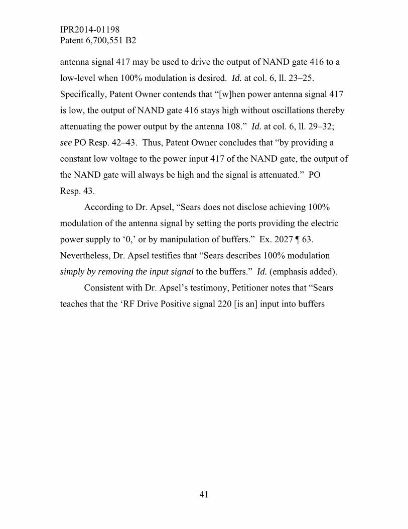
IPR2014-01198 Patent 6,700,551 B2
41
antenna signal 417 may be used to drive the output of NAND gate 416 to a
low-level when 100% modulation is desired. Id. at col. 6, ll. 23–25.
Specifically, Patent Owner contends that “[w]hen power antenna signal 417
is low, the output of NAND gate 416 stays high without oscillations thereby
attenuating the power output by the antenna 108.” Id. at col. 6, ll. 29–32;
see PO Resp. 42–43. Thus, Patent Owner concludes that “by providing a
constant low voltage to the power input 417 of the NAND gate, the output of
the NAND gate will always be high and the signal is attenuated.” PO
Resp. 43.
According to Dr. Apsel, “Sears does not disclose achieving 100%
modulation of the antenna signal by setting the ports providing the electric
power supply to ‘0,’ or by manipulation of buffers.” Ex. 2027 ¶ 63.
Nevertheless, Dr. Apsel testifies that “Sears describes 100% modulation
simply by removing the input signal to the buffers.” Id. (emphasis added).
Consistent with Dr. Apsel’s testimony, Petitioner notes that “Sears
teaches that the ‘RF Drive Positive signal 220 [is an] input into buffers

IPR2014-01198 Patent 6,700,551 B2
42
200A-200F.” Pet. Reply 6 (citing Ex. 1004, col. 4, ll. 15–20, Figs. 2, 4); see
Pet. 14. Sears’s Figure 2, as annotated by Petitioner, is reproduced below:
Figure 2 is a schematic diagram of a power amplifier with associated
circuitry in accordance with an embodiment of the Sears invention.
Ex. 1004, col. 2, ll. 14–16. Thus, referring to Sears’s Figure 4, the output of
NAND gate 416 is “RF Drive Positive 220,” which is the input to buffers
200A–200F, as depicted in Sears’s Figure 2. Because each buffer 200A–
200F is a tristate inverter (Ex. 1004, col. 4, ll. 36–42, Fig. 2), if, as Patent
Owner asserts, the input to buffers 200A–200F is always high during a
100% modulation, the output of buffers 200A–200F is always low (Ex. 1031
¶ 50; but see Paper 47, 6). Accordingly, Sears’s buffers 200A–200F are set
to zero when 100% modulation is performed, as recited in claim 2. Id.
Therefore, after considering both parties’ arguments and evidence, including

IPR2014-01198 Patent 6,700,551 B2
43
the testimony of Dr. Tentzeris and Dr. Apsel, we are persuaded that a person
of ordinary skill in the art would have understood that Sears teaches the
recited limitations of claim 2.
c. Claims 3 and 5
Petitioner maps in detail how the additional limitations of dependent
claims 3 and 5 are taught or suggested by Sears. Pet. 21–24. Patent Owner
does not contend that Sears does not teach these additional limitations. See
PO Resp. 41; Pet. Reply 7. We agree with and adopt Petitioner’s analysis of
Sears and mapping of Sears on the additional limitations of claims 3 and 5,
as set forth in the Petition.
For the reasons set forth above, Petitioner demonstrates by a
preponderance of the evidence that claims 1–3 and 5 are unpatentable over
Sears.
4. Obviousness over Sears and Nguyen
As noted above, Petitioner argues that Sears discloses all of the
limitations of the challenged claims, with the exception of the operation of a
control circuit recited in challenged claim 1. Pet. 24. Nevertheless,
Petitioner argues that Nguyen teaches “a tristatable buffer of the type
referenced by Sears, and expressly acknowledges that a tristatable buffer can
be set to ‘1,’ ‘0,’ or a high impedance state.” Id. (citing Ex. 1005, Abstract,
col. 1, ll. 10–18); Pet. Reply 7. Petitioner relies on the teachings of Nguyen
to provide more explicit detail of this feature. Pet. 24. In particular, Nguyen
teaches “an output line of a tristate device typically provides one of three
states: logic 0, logic 1, and high impedance.” Pet. Reply 4 (quoting
Ex. 1005, Abstract); see id. at Fig. 2, col. 1, ll. 16–18; Ex. 1031 ¶ 41.

IPR2014-01198 Patent 6,700,551 B2
44
Initially, Patent Owner contends that Nguyen fails to remedy the
deficiencies in Sears and that Nguyen only teaches a tristatable inverter. PO
Resp. 43–44. In particular, Patent Owner contends that Nguyen is directed
simply to inverters and not to any sort of radio-frequency device and that
Nguyen does not teach much more than inverters. Id. at 44. Consequently,
Patent Owner contends that Nguyen fails to teach the “setting” step, as
recited in claim 1, or “set[ting] to ‘0’, for 100% modulation of the antenna
signal,” as recited in claim 2. Id. As discussed above, however, Petitioner
argues, and we agree, that Sears, rather than Nguyen, teaches these
limitations. See supra Sections II.C.3.a. and b.
Petitioner further argues that a person of ordinary skill in the art
would have had reason to combine the teachings of Sears and Nguyen
because “Nguyen is configured to minimize switching delay in ‘integrated
circuit devices.’” Pet. 25 (citing Ex. 1005, col. 1, ll. 6–9; Ex. 1003 ¶ 55).
Alternatively, Petitioner contends that a person of ordinary skill in the art
would have understood that Nguyen’s device merely would have been the
substitution of a device operating in the same manner as Sears’s CMOS hex
inverter circuit. Id.; see Ex. 1003 ¶ 55; see also KSR, 550 U.S. at 416 (“The
Court recognized that when a patent claims a structure already known in the
prior art that is altered by the mere substitution of one element for another
known in the field, the combination must do more than yield a predictable
result.”).
Patent Owner contends that a person of ordinary skill in the art would
not have had reason to combine the teachings of Sears and Nguyen because
to do so would be contrary to Sears’s goals. PO Resp. 45–47. In particular,
Patent Owner contends that “Sears seeks to construct a power amplifier that

IPR2014-01198 Patent 6,700,551 B2
45
is ‘readily mass manufactured, power efficient, flexible and compact in
size.’” Id. at 46 (quoting Ex. 1004, col. 2, ll. 6–8). Further, Sears explains
that one of the advantages of its device is that it “uses a minimum number of
low power devices.” Ex. 1004, col. 7, ll. 52–55. Patent Owner contends,
however, that Nguyen’s inverters are complicated and include numerous
additional components. Ex. 2027 ¶ 68. Despite their complexity, Dr. Apsel
acknowledges that the inverters designed by Nguyen “do have certain
advantages.” Id. Dr. Apsel does not testify whether a person of ordinary
skill in the art would have found that any of those advantages outweigh the
disadvantage of greater complexity. Id. In particular, Dr. Apsel testifies that
It is possible, for instance, that a buffer design relying on Nguyen’s inverters would provide enough power to obviate the need for the parallel buffers in Sears’ circuit. Without knowing more design parameters (e.g., internal resistances, conductances, etc.), it would not be readily apparent that Nguyen’s inverters could be used in Sears’ circuit.
Id. ¶ 69 (emphasis added). Thus, Dr. Apsel acknowledges that it is unclear
whether Nguyen’s inverter would increase or reduce the complexity of the
Sears circuitry. Moreover, Dr. Apsel does not address whether the
combination of the teaching of Sears and Nguyen would fail to achieve any
of the other goals listed by Sears.
Therefore, we remain persuaded that either Nguyen’s detailed
description of the tristate operation of its inverter or the substitution of one
of Nguyen’s inverters for an equivalent device would have been sufficient
reason for a person of ordinary skill in the art to combine the teachings of
Sears and Nguyen to achieve the subject matter recited in the challenged
claims.

IPR2014-01198 Patent 6,700,551 B2
46
Patent Owner only disputes the combination of the teachings of Sears
and Nguyen, as those teachings are applied to claim 1. Petitioner relies on
Sears to supply the additional limitations of dependent claims 2, 3, and 5.
See Pet. 21–24. For the reasons set forth above with respect to Sears, we
agree with and adopt Petitioner’s analysis with respect to claims 2, 3, and 5.
For the reasons set forth above, Petitioner demonstrates by a
preponderance of the evidence that claims 1–3 and 5 are unpatentable over
Sears and Nguyen.
D. Motion to Exclude Evidence
Patent Owner filed a Motion to Exclude Evidence (Paper 49, “Mot. to
Excl.”). In particular, Patent Owner seeks to exclude (1) paragraphs 128–
134, 141–188, and 190–200 of Exhibit 1031, “under Fed. R. Evid. 401 as
not relevant to issues at trial because they were not cited in the Petitioner’s
Reply” (Mot. to Excl. 1–2); and (2) paragraphs 67–85 and 120–127 of
Exhibit 1031, “under Fed. R. Evid. 602 because Dr. Tentzeris has no
personal knowledge of the facts discussed in these paragraphs nor is he an
expert regarding them” (id. at 2–6). Petitioner filed an Opposition to Patent
Owner’s Motion to Exclude Evidence (Paper 53, “Opp. to Mot.”), and Patent
Owner filed a Reply to Petitioner’s Opposition to Patent Owner’s Motion to
Exclude Evidence (Paper 54, “Reply to Opp.”).
With respect to its first objection, Patent Owner contends that
“[n]owhere in the record does Petitioner rely on paragraphs 128–134, 141–
188, and 190–200 of the Reply Declaration or identify with any particularity
how these paragraphs are relevant to the issues in this proceeding.” Mot. to
Excl. 1. Because Petitioner does not rely on these paragraphs, Patent Owner
contends that these paragraphs cannot be relevant under Fed. R. Evid. 401 to

IPR2014-01198 Patent 6,700,551 B2
47
Petitioner’s Reply to the arguments or evidence presented in the Patent
Owner Response. Id. at 1–2. Petitioner disagrees and argues that
[E]ach paragraph is relevant to issues in this case because: (1) ¶¶128–134, which respond to PO’s actual reduction to practice evidence, are referenced in an unchallenged paragraph of Dr. Tentzeris’ declaration (¶66) and discuss evidence also discussed in other relevant paragraphs (¶¶66 and 77); and (2) ¶¶141–188 and ¶¶190–199 address specific evidence raised by PO in its PO Response. ¶200 is simply Dr. Tentzeris’ concluding paragraph.
Opp. to Mot. 2. Patent Owner replies that Petitioner is merely seeking to
place “the burden on the Board to sift through the Reply and accompanying
Declaration to determine which paragraphs were properly cited and relied on
and then determine the appropriate weight.” Reply to Opp. 1.
We agree with Petitioner that Patent Owner’s objections to
paragraphs 128–134, 141–188, and 190–200 of Exhibit 1031 go to the
weight to be given this evidence, rather than to its admissibility. The Board,
sitting as a non-jury tribunal with administrative expertise, is well positioned
to determine and assign appropriate weight and/or relevance to evidence
presented. See Gnosis S.p.A. v. S. Ala. Med. Sci. Found., Case IPR2013-
00118, slip op. at 43 (PTAB June 20, 2014) (Paper 64). Therefore, we deny
Patent Owner’s request to exclude these paragraphs.
With respect to its second objection, Patent Owner contends
that, in paragraphs 67–85 and 120–127 of Exhibit 1031,
Petitioner has offered Dr. Tentzeris as an expert on technical issues and not as to the facts leading up to the development of the M210H device at INSIDE. Dr. Tentzeris is not an expert regarding these facts and possesses no personal knowledge of them. . . . Dr. Tentzeris’ opinions regarding these facts is not based on his technical expertise or his own personal knowledge. Instead, Petitioners use the Reply Declaration to give the

IPR2014-01198 Patent 6,700,551 B2
48
appearance of expert authority to what is otherwise a meritless attorney argument.
Mot. to Excl. 2–3. In particular, Patent Owner contends that paragraphs 67–
85 of Exhibit 1031 contain unfounded speculation on the dates of exhibits
and are not based on Dr. Tentzeris’s personal knowledge. Id. at 3–4.
Further, Patent Owner contends paragraphs 120–127 of Exhibit 1031
“contain unfounded speculation regarding software development for the
M210H Prototype and are not based on Dr. Tentzeris’ personal knowledge
or expertise.” Id. at 4–6 (emphasis omitted). Because we do not rely on
paragraphs 67–85 and 120–127 of Exhibit 1031 in reaching our decision
here, we dismiss Patent Owner’s Motion to Exclude Evidence, with respect
to these paragraphs, as moot.
III. CONCLUSION
Petitioner demonstrates by a preponderance of the evidence that
claims 1–3 and 5 of the ʼ551 patent are unpatentable.
IV. ORDER
For the reasons given, it is
ORDERED that claims 1–3 and 5 of the ’551 patent are unpatentable
as
1. rendered obvious over Sears; and
2. rendered obvious over Sears and Nguyen;
FURTHER ORDERED that Patent Owner’s Motion to Exclude
Evidence (Paper 49) is denied with respect to paragraphs 128–134, 141–188,
and 190–200 of Exhibit 1031 and dismissed as moot with respect to
paragraphs 67–85 of Exhibit 1031; and

IPR2014-01198 Patent 6,700,551 B2
49
FURTHER ORDERED that, because this is a final decision, parties to
the proceeding seeking judicial review of the decision must comply with the
notice and service requirements of 37 C.F.R. § 90.2.
PETITIONER: Bing Ai Matthew Bernstein Miguel Bombach Thomas N. Millikan PERKINS COIE LLP [email protected] [email protected] [email protected] [email protected] [email protected] PATENT OWNER: Jon E. Wright John H. Curry Amirali Sharifi STERNE, KESSLER, GOLDSTAIN & FOX P.L.L.C. [email protected] [email protected] [email protected] Robert Auchter MCKOOL SMITH, P.C. [email protected]