Tri-phase TPG and TPG with SCADA control instructions · Tri-Phase, TPG, and TPG with SCADA...
20
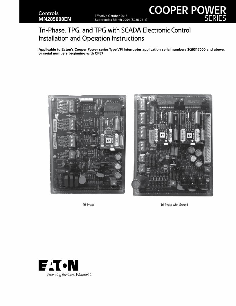
Tri-Phase, TPG, and TPG with SCADA Electronic Control Installation and Operation Instructions Applicable to Eaton’s Cooper Power series Type VFI Interrupter application serial numbers 3Q9317000 and above, or serial numbers beginning with CP57 Tri-Phase Tri-Phase with Ground COOPER POWER SERIES Controls MN285008EN Effective October 2016 Supersedes March 2004 (S285-75-1)
Transcript of Tri-phase TPG and TPG with SCADA control instructions · Tri-Phase, TPG, and TPG with SCADA...
Tri-Phase, TPG, and TPG with SCADA Electronic Control Installation and Operation InstructionsApplicable to Eaton’s Cooper Power series Type VFI Interrupter application serial numbers 3Q9317000 and above, or serial numbers beginning with CP57
Tri-Phase Tri-Phase with Ground
COOPER POWERSERIES
Controls MN285008EN
Effective October 2016Supersedes March 2004 (S285-75-1)
ii InstallatIon and operatIon InstructIons MN285008EN October 2016
DISCLAIMER OF WARRANTIES AND LIMITATION OF LIABILITY
The information, recommendations, descriptions and safety notations in this document are based on Eaton Corporation’s (“Eaton”) experience and judgment and may not cover all contingencies. If further information is required, an Eaton sales office should be consulted. Sale of the product shown in this literature is subject to the terms and conditions outlined in appropriate Eaton selling policies or other contractual agreement between Eaton and the purchaser.
THERE ARE NO UNDERSTANDINGS, AGREEMENTS, WARRANTIES, EXPRESSED OR IMPLIED, INCLUDING WARRANTIES OF FITNESS FOR A PARTICULAR PURPOSE OR MERCHANTABILITY, OTHER THAN THOSE SPECIFICALLY SET OUT IN ANY EXISTING CONTRACT BETWEEN THE PARTIES. ANY SUCH CONTRACT STATES THE ENTIRE OBLIGATION OF EATON. THE CONTENTS OF THIS DOCUMENT SHALL NOT BECOME PART OF OR MODIFY ANY CONTRACT BETWEEN THE PARTIES.
In no event will Eaton be responsible to the purchaser or user in contract, in tort (including negligence), strict liability or other-wise for any special, indirect, incidental or consequential damage or loss whatsoever, including but not limited to damage or loss of use of equipment, plant or power system, cost of capital, loss of power, additional expenses in the use of existing power facilities, or claims against the purchaser or user by its customers resulting from the use of the information, recommendations and descriptions contained herein. The information contained in this manual is subject to change without notice.
iiiInstallatIon and operatIon InstructIons MN285008EN October 2016
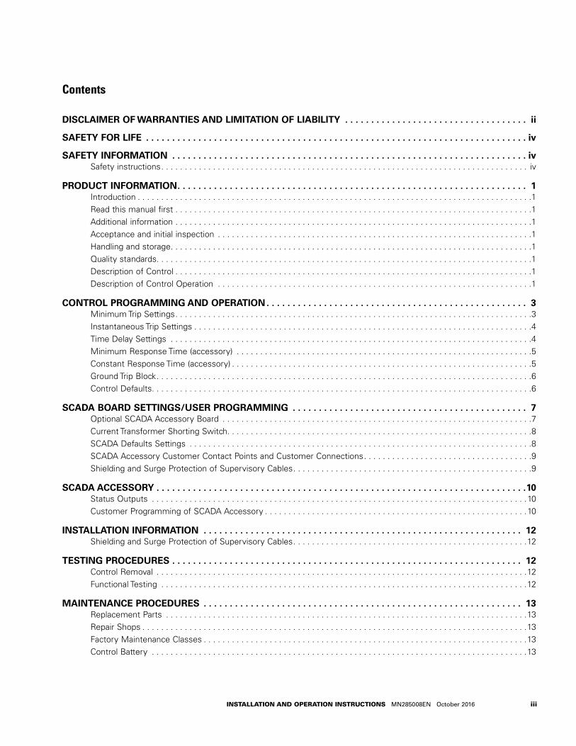
Contents
DISCLAIMER OF WARRANTIES AND LIMITATION OF LIABILITY . . . . . . . . . . . . . . . . . . . . . . . . . . . . . . . . . . . ii
SAFETY FOR LIFE . . . . . . . . . . . . . . . . . . . . . . . . . . . . . . . . . . . . . . . . . . . . . . . . . . . . . . . . . . . . . . . . . . . . . . . . . iv
SAFETY INFORMATION . . . . . . . . . . . . . . . . . . . . . . . . . . . . . . . . . . . . . . . . . . . . . . . . . . . . . . . . . . . . . . . . . . . . ivSafety instructions . . . . . . . . . . . . . . . . . . . . . . . . . . . . . . . . . . . . . . . . . . . . . . . . . . . . . . . . . . . . . . . . . . . . . . . . . . . . . . iv
PRODUCT INFORMATION . . . . . . . . . . . . . . . . . . . . . . . . . . . . . . . . . . . . . . . . . . . . . . . . . . . . . . . . . . . . . . . . . . . 1Introduction . . . . . . . . . . . . . . . . . . . . . . . . . . . . . . . . . . . . . . . . . . . . . . . . . . . . . . . . . . . . . . . . . . . . . . . . . . . . . . . . . . . .1Read this manual first . . . . . . . . . . . . . . . . . . . . . . . . . . . . . . . . . . . . . . . . . . . . . . . . . . . . . . . . . . . . . . . . . . . . . . . . . . . .1Additional information . . . . . . . . . . . . . . . . . . . . . . . . . . . . . . . . . . . . . . . . . . . . . . . . . . . . . . . . . . . . . . . . . . . . . . . . . . . .1Acceptance and initial inspection . . . . . . . . . . . . . . . . . . . . . . . . . . . . . . . . . . . . . . . . . . . . . . . . . . . . . . . . . . . . . . . . . . .1Handling and storage . . . . . . . . . . . . . . . . . . . . . . . . . . . . . . . . . . . . . . . . . . . . . . . . . . . . . . . . . . . . . . . . . . . . . . . . . . . . .1Quality standards. . . . . . . . . . . . . . . . . . . . . . . . . . . . . . . . . . . . . . . . . . . . . . . . . . . . . . . . . . . . . . . . . . . . . . . . . . . . . . . .1Description of Control . . . . . . . . . . . . . . . . . . . . . . . . . . . . . . . . . . . . . . . . . . . . . . . . . . . . . . . . . . . . . . . . . . . . . . . . . . . .1Description of Control Operation . . . . . . . . . . . . . . . . . . . . . . . . . . . . . . . . . . . . . . . . . . . . . . . . . . . . . . . . . . . . . . . . . . .1
CONTROL PROGRAMMING AND OPERATION . . . . . . . . . . . . . . . . . . . . . . . . . . . . . . . . . . . . . . . . . . . . . . . . . . 3Minimum Trip Settings . . . . . . . . . . . . . . . . . . . . . . . . . . . . . . . . . . . . . . . . . . . . . . . . . . . . . . . . . . . . . . . . . . . . . . . . . . . .3Instantaneous Trip Settings . . . . . . . . . . . . . . . . . . . . . . . . . . . . . . . . . . . . . . . . . . . . . . . . . . . . . . . . . . . . . . . . . . . . . . . .4Time Delay Settings . . . . . . . . . . . . . . . . . . . . . . . . . . . . . . . . . . . . . . . . . . . . . . . . . . . . . . . . . . . . . . . . . . . . . . . . . . . . .4Minimum Response Time (accessory) . . . . . . . . . . . . . . . . . . . . . . . . . . . . . . . . . . . . . . . . . . . . . . . . . . . . . . . . . . . . . . .5Constant Response Time (accessory) . . . . . . . . . . . . . . . . . . . . . . . . . . . . . . . . . . . . . . . . . . . . . . . . . . . . . . . . . . . . . . . .5Ground Trip Block . . . . . . . . . . . . . . . . . . . . . . . . . . . . . . . . . . . . . . . . . . . . . . . . . . . . . . . . . . . . . . . . . . . . . . . . . . . . . . . .6Control Defaults. . . . . . . . . . . . . . . . . . . . . . . . . . . . . . . . . . . . . . . . . . . . . . . . . . . . . . . . . . . . . . . . . . . . . . . . . . . . . . . . .6
SCADA BOARD SETTINGS/USER PROGRAMMING . . . . . . . . . . . . . . . . . . . . . . . . . . . . . . . . . . . . . . . . . . . . . 7Optional SCADA Accessory Board . . . . . . . . . . . . . . . . . . . . . . . . . . . . . . . . . . . . . . . . . . . . . . . . . . . . . . . . . . . . . . . . . .7Current Transformer Shorting Switch. . . . . . . . . . . . . . . . . . . . . . . . . . . . . . . . . . . . . . . . . . . . . . . . . . . . . . . . . . . . . . . . .8SCADA Defaults Settings . . . . . . . . . . . . . . . . . . . . . . . . . . . . . . . . . . . . . . . . . . . . . . . . . . . . . . . . . . . . . . . . . . . . . . . . .8SCADA Accessory Customer Contact Points and Customer Connections . . . . . . . . . . . . . . . . . . . . . . . . . . . . . . . . . . . .9Shielding and Surge Protection of Supervisory Cables . . . . . . . . . . . . . . . . . . . . . . . . . . . . . . . . . . . . . . . . . . . . . . . . . . .9
SCADA ACCESSORY . . . . . . . . . . . . . . . . . . . . . . . . . . . . . . . . . . . . . . . . . . . . . . . . . . . . . . . . . . . . . . . . . . . . . . .10Status Outputs . . . . . . . . . . . . . . . . . . . . . . . . . . . . . . . . . . . . . . . . . . . . . . . . . . . . . . . . . . . . . . . . . . . . . . . . . . . . . . . .10Customer Programming of SCADA Accessory . . . . . . . . . . . . . . . . . . . . . . . . . . . . . . . . . . . . . . . . . . . . . . . . . . . . . . . .10
INSTALLATION INFORMATION . . . . . . . . . . . . . . . . . . . . . . . . . . . . . . . . . . . . . . . . . . . . . . . . . . . . . . . . . . . . . 12Shielding and Surge Protection of Supervisory Cables . . . . . . . . . . . . . . . . . . . . . . . . . . . . . . . . . . . . . . . . . . . . . . . . . .12
TESTING PROCEDURES . . . . . . . . . . . . . . . . . . . . . . . . . . . . . . . . . . . . . . . . . . . . . . . . . . . . . . . . . . . . . . . . . . . 12Control Removal . . . . . . . . . . . . . . . . . . . . . . . . . . . . . . . . . . . . . . . . . . . . . . . . . . . . . . . . . . . . . . . . . . . . . . . . . . . . . . .12Functional Testing . . . . . . . . . . . . . . . . . . . . . . . . . . . . . . . . . . . . . . . . . . . . . . . . . . . . . . . . . . . . . . . . . . . . . . . . . . . . . .12
MAINTENANCE PROCEDURES . . . . . . . . . . . . . . . . . . . . . . . . . . . . . . . . . . . . . . . . . . . . . . . . . . . . . . . . . . . . . 13Replacement Parts . . . . . . . . . . . . . . . . . . . . . . . . . . . . . . . . . . . . . . . . . . . . . . . . . . . . . . . . . . . . . . . . . . . . . . . . . . . . .13Repair Shops . . . . . . . . . . . . . . . . . . . . . . . . . . . . . . . . . . . . . . . . . . . . . . . . . . . . . . . . . . . . . . . . . . . . . . . . . . . . . . . . . .13Factory Maintenance Classes . . . . . . . . . . . . . . . . . . . . . . . . . . . . . . . . . . . . . . . . . . . . . . . . . . . . . . . . . . . . . . . . . . . . .13Control Battery . . . . . . . . . . . . . . . . . . . . . . . . . . . . . . . . . . . . . . . . . . . . . . . . . . . . . . . . . . . . . . . . . . . . . . . . . . . . . . . .13
iv
Tri-Phase, TPG, and TPG with SCADA Electronic Control KA20480392
InstallatIon and operatIon InstructIons MN285008EN October 2016
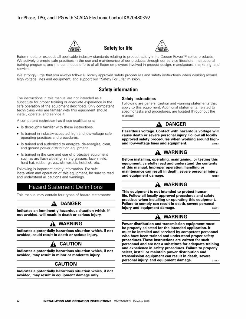
Safety for life
Eaton meets or exceeds all applicable industry standards relating to product safety in its Cooper Power™ series products. We actively promote safe practices in the use and maintenance of our products through our service literature, instructional training programs, and the continuous efforts of all Eaton employees involved in product design, manufacture, marketing, and service.
We strongly urge that you always follow all locally approved safety procedures and safety instructions when working around high voltage lines and equipment, and support our “Safety For Life” mission.
Safety information
The instructions in this manual are not intended as a substitute for proper training or adequate experience in the safe operation of the equipment described. Only competent technicians who are familiar with this equipment should install, operate, and service it.
A competent technician has these qualifications:
●● Is thoroughly familiar with these instructions.
●● Is trained in industry-accepted high and low-voltage safe operating practices and procedures.
●● Is trained and authorized to energize, de-energize, clear, and ground power distribution equipment.
●● Is trained in the care and use of protective equipment such as arc flash clothing, safety glasses, face shield, hard hat, rubber gloves, clampstick, hotstick, etc.
Following is important safety information. For safe installation and operation of this equipment, be sure to read and understand all cautions and warnings.
Hazard Statement DefinitionsThis manual may contain four types of hazard statements:
DANGERIndicates an imminently hazardous situation which, if not avoided, will result in death or serious injury .
WARNINGIndicates a potentially hazardous situation which, if not avoided, could result in death or serious injury .
CAUTIONIndicates a potentially hazardous situation which, if not avoided, may result in minor or moderate injury .
CAUTIONIndicates a potentially hazardous situation which, if not avoided, may result in equipment damage only .
Safety instructionsFollowing are general caution and warning statements that apply to this equipment. Additional statements, related to specific tasks and procedures, are located throughout the manual.
DANGERHazardous voltage . Contact with hazardous voltage will cause death or severe personal injury . Follow all locally approved safety procedures when working around high- and low-voltage lines and equipment . G103 .3
WARNINGBefore installing, operating, maintaining, or testing this equipment, carefully read and understand the contents of this manual . Improper operation, handling or maintenance can result in death, severe personal injury, and equipment damage . G101 .0
WARNINGThis equipment is not intended to protect human life . Follow all locally approved procedures and safety practices when installing or operating this equipment . Failure to comply can result in death, severe personal injury and equipment damage . G102 .1
WARNINGPower distribution and transmission equipment must be properly selected for the intended application . It must be installed and serviced by competent personnel who have been trained and understand proper safety procedures . These instructions are written for such personnel and are not a substitute for adequate training and experience in safety procedures . Failure to properly select, install or maintain power distribution and transmission equipment can result in death, severe personal injury, and equipment damage . G122 .3
!SAFETYFOR LIFE
!SAFETYFOR LIFE
1
Tri-Phase, TPG, and TPG with SCADA Electronic Control KA20480392
InstallatIon and operatIon InstructIons MN285008EN October 2016
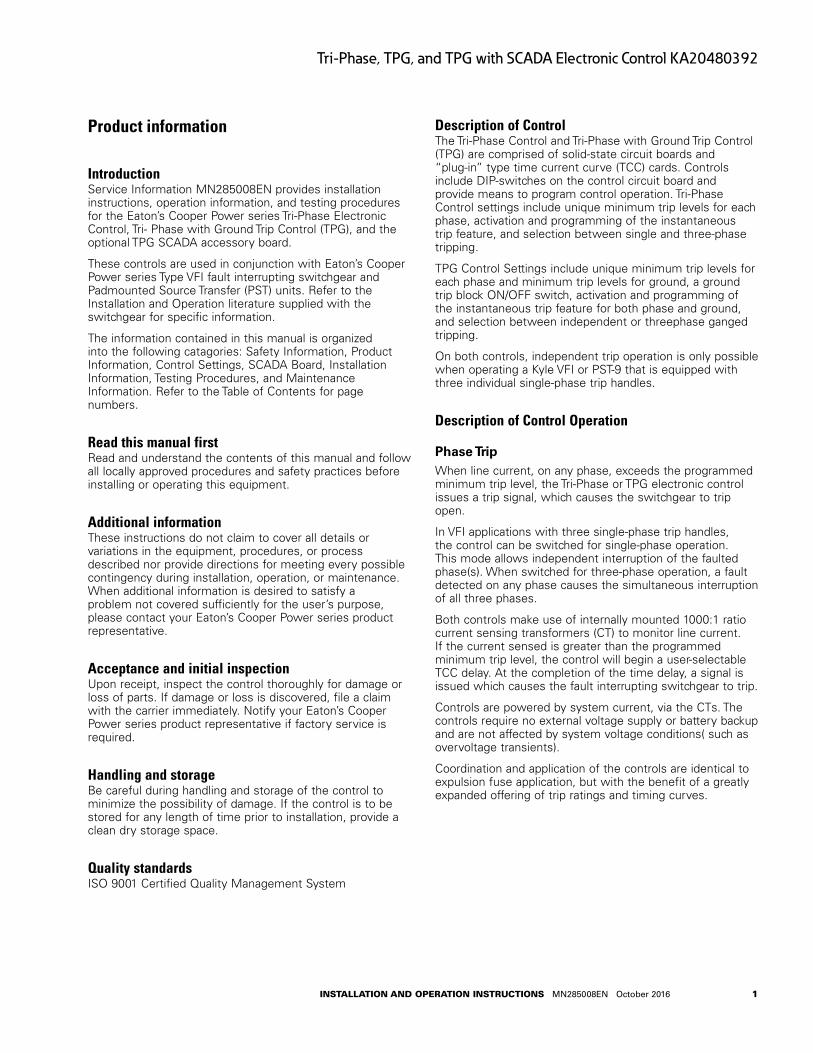
Product information
IntroductionService Information MN285008EN provides installation instructions, operation information, and testing procedures for the Eaton’s Cooper Power series Tri-Phase Electronic Control, Tri- Phase with Ground Trip Control (TPG), and the optional TPG SCADA accessory board.
These controls are used in conjunction with Eaton’s Cooper Power series Type VFI fault interrupting switchgear and Padmounted Source Transfer (PST) units. Refer to the Installation and Operation literature supplied with the switchgear for specific information.
The information contained in this manual is organized into the following catagories: Safety Information, Product Information, Control Settings, SCADA Board, Installation Information, Testing Procedures, and Maintenance Information. Refer to the Table of Contents for page numbers.
Read this manual firstRead and understand the contents of this manual and follow all locally approved procedures and safety practices before installing or operating this equipment.
Additional informationThese instructions do not claim to cover all details or variations in the equipment, procedures, or process described nor provide directions for meeting every possible contingency during installation, operation, or maintenance. When additional information is desired to satisfy a problem not covered sufficiently for the user’s purpose, please contact your Eaton’s Cooper Power series product representative.
Acceptance and initial inspectionUpon receipt, inspect the control thoroughly for damage or loss of parts. If damage or loss is discovered, file a claim with the carrier immediately. Notify your Eaton’s Cooper Power series product representative if factory service is required.
Handling and storageBe careful during handling and storage of the control to minimize the possibility of damage. If the control is to be stored for any length of time prior to installation, provide a clean dry storage space.
Quality standardsISO 9001 Certified Quality Management System
Description of ControlThe Tri-Phase Control and Tri-Phase with Ground Trip Control (TPG) are comprised of solid-state circuit boards and “plug-in” type time current curve (TCC) cards. Controls include DIP-switches on the control circuit board and provide means to program control operation. Tri-Phase Control settings include unique minimum trip levels for each phase, activation and programming of the instantaneous trip feature, and selection between single and three-phase tripping.
TPG Control Settings include unique minimum trip levels for each phase and minimum trip levels for ground, a ground trip block ON/OFF switch, activation and programming of the instantaneous trip feature for both phase and ground, and selection between independent or threephase ganged tripping.
On both controls, independent trip operation is only possible when operating a Kyle VFI or PST-9 that is equipped with three individual single-phase trip handles.
Description of Control Operation
Phase TripWhen line current, on any phase, exceeds the programmed minimum trip level, the Tri-Phase or TPG electronic control issues a trip signal, which causes the switchgear to trip open.
In VFI applications with three single-phase trip handles, the control can be switched for single-phase operation. This mode allows independent interruption of the faulted phase(s). When switched for three-phase operation, a fault detected on any phase causes the simultaneous interruption of all three phases.
Both controls make use of internally mounted 1000:1 ratio current sensing transformers (CT) to monitor line current. If the current sensed is greater than the programmed minimum trip level, the control will begin a user-selectable TCC delay. At the completion of the time delay, a signal is issued which causes the fault interrupting switchgear to trip.
Controls are powered by system current, via the CTs. The controls require no external voltage supply or battery backup and are not affected by system voltage conditions( such as overvoltage transients).
Coordination and application of the controls are identical to expulsion fuse application, but with the benefit of a greatly expanded offering of trip ratings and timing curves.
2
Tri-Phase, TPG, and TPG with SCADA Electronic Control KA20480392
InstallatIon and operatIon InstructIons MN285008EN October 2016
Ground TripTPG controls make use of the same internally mounted 1000:1 ratio current-sensing transformers (CTs) on each phase to monitor line current used for phase tripping. Additional CTs are not required.
If the Ground Trip feature is activated when phase imbalance exceeds the programmed minimum trip level, the TPG electronic control issues a trip signal, causing the VFI mechanism to trip OPEN.
Phase or Ground Minimum TripMinimum-trip settings for each phase are DIP-switch selectable, allowing convenient configuration to meet specific application requirements.
At normal system current levels below minimum trip, a Tri- Phase of TPG control is effectively dormant.
Phase current levels are continuously being compared to the programmed minimum trip values. However, the TCC and trip circuits remain inactive. The TCC circuit is activated whenever current above the pre-selected minimum trip value is sensed.
Time DelayThe time—current curve (TCC) delay circuit is a modular, plug-in, printed circuit card, which is available as a separate part for field configuration of the control. A variety of field replaceable TCC modules are available: each provides a fixed time current curve characteristic. The range of curves available enables coordination between the Tri- Phase or TPG control and other protective equipment.
The TCC card is a resistor—capacitor network which sets the response time characteristics of the control for line currents above minimum trip. The trip circuit compares the output voltage from the time delay circuit to a fixed reference voltage. Once the output voltage equals the reference voltage, the trip circuit pulses the flux-shift tripper(s), causing the switchgear to open.
Output from the trip circuit is held by the inhibitor circuit until the trip capacitors have sufficient charge to operate the flux-shift tripper(s).
Tri-Phase controls require one TCC card for phase sensing.
Available TCC cards for Tri-Phase controls include the EF, TF, KF, H, and F curves; refer to Reference Information R285-91-3 for additional information.
TPG controls require two TCC cards, one for phase sensing and one for phase imbalance (ground sensing).
Available TCC cards for the TPG control include the F, H, EF, TF and KF curves. Refer to Reference Information R285-91-3 for further information.
Instantaneous TripInstantaneous Trip-phase is a standard feature of both the Tri-Phase and TPG controls. Both bypass the normal time-delay charateristics to provide instantaneous tripping
in response to high magnitude faults. With instantaneous trip, fault duration is reduced and coordination with source-side protection is extended, through improved system coordination and selective zoning.
A DIP-switch package, on the control circuit board, enables the instantaneous trip feature and programs a multiplier. The multiplier is applied to the standard minimum trip settings for each phase, to determine instantaneous trip actuation levels. TPG controls provide an additional DIP-switch for instantaneous trip-ground. When current exceeds the actuation level, the feature causes the control to trip immediately, thus eliminating any intentional time delay. For faults below the actuation level, the control operates according to normal TCC characteristics.
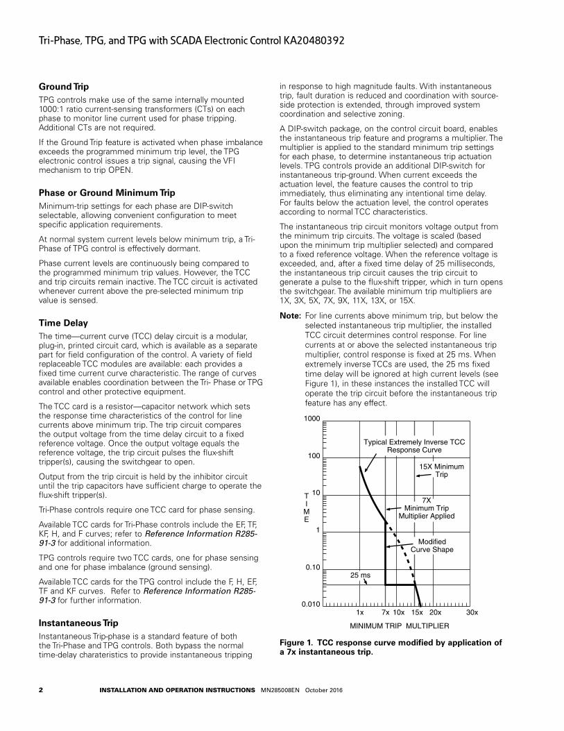
The instantaneous trip circuit monitors voltage output from the minimum trip circuits. The voltage is scaled (based upon the minimum trip multiplier selected) and compared to a fixed reference voltage. When the reference voltage is exceeded, and, after a fixed time delay of 25 milliseconds, the instantaneous trip circuit causes the trip circuit to generate a pulse to the flux-shift tripper, which in turn opens the switchgear. The available minimum trip multipliers are 1X, 3X, 5X, 7X, 9X, 11X, 13X, or 15X.
otee:N For line currents above minimum trip, but below the selected instantaneous trip multiplier, the installed TCC circuit determines control response. For line currents at or above the selected instantaneous trip multiplier, control response is fixed at 25 ms. When extremely inverse TCCs are used, the 25 ms fixed time delay will be ignored at high current levels (see Figure 1), in these instances the installed TCC will operate the trip circuit before the instantaneous trip feature has any effect.
TIME
1000
100
10
1
0.10
0.010
MINIMUM TRIP MULTIPLIER
30x 20x10x1x
Typical Extremely Inverse TCCResponse Curve
7XMinimum Trip
Multiplier Applied
ModifiedCurve Shape
25 ms
15X MinimumTrip
7x 15x
Figure 1 . TCC response curve modified by application of a 7x instantaneous trip .
3
Tri-Phase, TPG, and TPG with SCADA Electronic Control KA20480392
InstallatIon and operatIon InstructIons MN285008EN October 2016
Control Programming and Operation
CAUTIONEquipment misoperation . Do not energize this equipment until all control settings have been properly programmed and verified . Refer to the Control Programming and Operation section of this manual for programming procedures . Failure to comply can result in misoperation (unintended operation), equipment damage and personal injury . G118 .1
otee:N Changes to the control operating parameters should be made only by a qualified technician or engineer.
Minimum Trip SettingsThe three minimum trip DIP-switch packages allow separate minimum trip levels for each phase. On the TPG control, there is an additional DIP-switch package that allows the minimum trip level for ground to be set.
IMPORTANTMinimum trip levels can be changed while the fault interrupter is in service; however, to avoid nuisance trips, move all DIP switches, for the phase to be changed, to the ON position. Switch DIP switches OFF, as required, to obtain the desired minimum trip level.
otee:N Failure to follow this procedure could result in a minimum trip setting being inadvertently placed below the preset load current levels resulting in an unwanted trip operation.
10A
SW1
SW2
Switches 1, 2, and 3 (switch 3 not shown) used to set minimum trip for phase levels.
10A
20A
20A
40A
40A
80A
80A
160A
160A
320A
320A
640A
640A
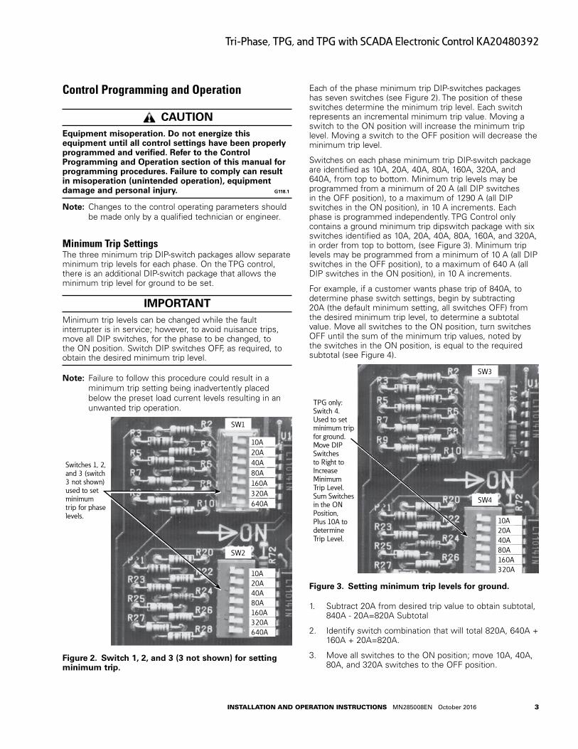
Figure 2 . Switch 1, 2, and 3 (3 not shown) for setting minimum trip .
Each of the phase minimum trip DIP-switches packages has seven switches (see Figure 2). The position of these switches determine the minimum trip level. Each switch represents an incremental minimum trip value. Moving a switch to the ON position will increase the minimum trip level. Moving a switch to the OFF position will decrease the minimum trip level.
Switches on each phase minimum trip DIP-switch package are identified as 10A, 20A, 40A, 80A, 160A, 320A, and 640A, from top to bottom. Minimum trip levels may be programmed from a minimum of 20 A (all DIP switches in the OFF position), to a maximum of 1290 A (all DIP switches in the ON position), in 10 A increments. Each phase is programmed independently. TPG Control only contains a ground minimum trip dipswitch package with six switches identified as 10A, 20A, 40A, 80A, 160A, and 320A, in order from top to bottom, (see Figure 3). Minimum trip levels may be programmed from a minimum of 10 A (all DIP switches in the OFF position), to a maximum of 640 A (all DIP switches in the ON position), in 10 A increments.
For example, if a customer wants phase trip of 840A, to determine phase switch settings, begin by subtracting 20A (the default minimum setting, all switches OFF) from the desired minimum trip level, to determine a subtotal value. Move all switches to the ON position, turn switches OFF until the sum of the minimum trip values, noted by the switches in the ON position, is equal to the required subtotal (see Figure 4).
SW3
SW4
TPG only:Switch 4.Used to set minimum trip for ground. Move DIP Switches to Right to Increase Minimum Trip Level. Sum Switches in the ON Position, Plus 10A to determine Trip Level.
10A20A40A80A160A320A
Figure 3 . Setting minimum trip levels for ground .
1. Subtract 20A from desired trip value to obtain subtotal, 840A - 20A=820A Subtotal
2. Identify switch combination that will total 820A, 640A + 160A + 20A=820A.
3. Move all switches to the ON position; move 10A, 40A, 80A, and 320A switches to the OFF position.
4
Tri-Phase, TPG, and TPG with SCADA Electronic Control KA20480392
InstallatIon and operatIon InstructIons MN285008EN October 2016
OFF-ON
10A
20A . . . . . . . . . . . . . . 20A
40A
80A
160A . . . . . . . . . . . . . 160A
320A
640A . . . . . . . . . . . . . +640A
Subtotal . . . . . . . . . . . 820A
Default Min. . . . . . . . . +20A
Total . . . . . . . . . . . . . . 840A
Switch shown in OFF position
KEY
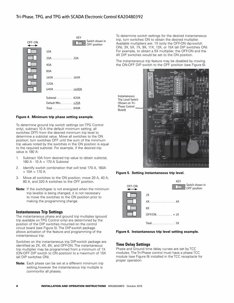
Figure 4 . Minimum trip phase setting example .
To determine ground trip switch settings (on TPG Control only), subtract 10 A (the default minimum setting, all switches OFF) from the desired minimum trip level to determine a subtotal value. Move all switches to the ON position; turn switches OFF until the sum of the minimum trip values noted by the switches in the ON position is equal to the required subtotal. For example, if the desired trip value is 180 A:
1. Subtract 10A from desired trip value to obtain subtotal, 180 A - 10 A = 170 A Subtotal
2. Identify switch combination that will total 170 A, 160A + 10A = 170 A.
3. Move all switches to the ON position; move 20 A, 40 A, 80 A, and 320 A switches to the OFF position.
otee:N If the switchgear is not energized when the minimum trip level(s) is being changed, it is not necessary to move the switches to the ON position prior to making the programming change.
Instantaneous Trip SettingsThe instantaneous phase and ground trip multiples (ground trip available on TPG Control only) are determined by the position of the DIP switches mounted on the control circuit board (see Figure 5). The DIP-switch package allows activation of the feature and programming of the instantaneous trip.
Switches on the instantaneous trip DIP-switch package are identified as 2X, 4X, 8X, and OFF-ON. The instantaneous trip multiplier may be programmed from a minimum of 1X (ON-OFF DIP switch to ON position) to a maximum of 15X (all DIP switches ON).
otee:N Each phase can be set at a different minimum trip setting,however the instantaneous trip multiple is commonfor all phases.
To determine switch settings for the desired instantaneous trip, turn switches ON to obtain the desired multiplier. Available multipliers are: 1X (only the OFF-ON dip-switch ON), 3X, 5X, 7X, 9X, 11X, 13X, or 15X (all DIP switches ON). For example, to obtain a 5X multiplier, the OFF-ON and the 4X DIP switches would be set to the ON position.
The instantaneous trip feature may be disabled by moving the ON-OFF DIP switch to the OFF position (see Figure 6).
Instantaneous Trip Level Switch (Shown on Tri-Phase Control Board)
Figure 5 . Setting instantaneous trip level .
OFF-ON
2X
4X . . . . . . . . . . . . . . . . . . 4X
8X
OFF/ON . . . . . . . . . . . + 1X
Total . . . . . . . . . . . . . . . . 5X
Switch shown in OFF position
KEY
Figure 6 . Instantaneous trip level setting example .
Time Delay SettingsPhase and Ground time delay curves are set by TCC modules. The Tri-Phase control must have a phase TCC module (see Figure 9) installed in the TCC receptacle for proper operation.
5
Tri-Phase, TPG, and TPG with SCADA Electronic Control KA20480392
InstallatIon and operatIon InstructIons MN285008EN October 2016
TPG controls require two TCC modules. Phase is installed in the TCC 1 receptacle socket and Ground is installed in the TCC 2 receptacle socket (see Figure 10). If TCC modules are missing or removed, phase current over minimum trip, or a phase imbalance (ground) over minimum trip, the switchgear will trip without any intentional time delay (approximately 20 milliseconds).
To remove or change out TCC cards, follow this procedure:
1. De-energize switchgear.
2. Remove/open control housing cover.
3. Remove TCC card by pushing back retainer clip and lifting up plastic edge to disengage TCC module from plastic support post. Pull module free from receptacle.
4. Install replacement TCC module into receptacle, (component side up); snap into plastic support post to retain.
otee:N The TCC module is keyed so that it cannot be inserted unless it is properly aligned. If card will not insert, note location of key and retry.
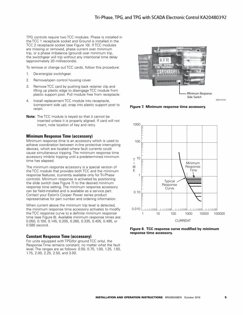
Minimum Response Time (accessory)Minimum response time is an accessory which is used to achieve coordination between in-line protective interrupting devices, which are located where fault currents could cause simultaneous tripping. The minimum response time accessory inhibits tripping until a predetermined minimum time has elapsed.
The minimum response accessory is a special version of the TCC module that provides both TCC and the minimum response features, (currently available only for Tri-Phase controls). Minimum response is activated by positioning the slide switch (see Figure 7) to the desired minimum response time setting. The minimum response accessory can be field-installed and is available as a service part. Contact your Eaton’s Cooper Power series product representative for part number and ordering information.
When current above the minimum trip level is detected, the minimum response time accessory activates to modify the TCC response curve to a definite minimum response time (see Figure 8). Available minimum response times are: 0.050, 0.100, 0.145, 0.205, 0.260, 0.335, 0.405, 0.495, or 0.580 second.
Constant Response Time (accessory)For units equipped with TPG(for ground TCC only), the Response Time remains constant, no matter what the fault level. The ranges are as follows: 0.50, 0.75, 1.00, 1.25, 1.50, 1.75, 2.00, 2.25, 2.50, and 3.00.
Minimum Response Side Switch
98007KMA
Figure 7 . Minimum response time accessory .
TIME
1000
100
10
1
0.10
0.010
CURRENT
100000100001000100101
TypicalResponse
Curve
MinimumResponse
Time
Figure 8 . TCC response curve modified by minimum response time accessory .
6
Tri-Phase, TPG, and TPG with SCADA Electronic Control KA20480392
InstallatIon and operatIon InstructIons MN285008EN October 2016
Ground Trip BlockTPG Control only: Ground Trip can be blocked by using the ON/OFF Ground Trip Block DIP switch on the basic TPG board (see Figure 10).
When the optional SCADA accessory is ordered, an additional ON/OFF toggle switch is located adjacent to the TPG and SCADA boards.
Control DefaultsUnless otherwise specified, units will be shipped with the following setting defaults.
Tri-Phase ControlPhase minimum trip setting of 80 A on A, B, and C Phase. Instantaneous Trip, Phase (OFF). Independent/Ganged operation switch set to GANGED.
TPG Control (if equipped)Phase minimum trip setting of 80 A on A, B, and C Phase. Ground Minimum Trip setting of 40 A. Instantaneous Trip, Phase (OFF). Ground Trip Block, (OFF). Independent/Ganged operation switch set to GANGED.
SCADA (if equipped)Emergency Minimum Trip Multiplier (OFF). Inrush Restraint Minimum Trip Multiples (OFF). Ground Trip Block (NORMAL). CT Shorting Switch (NORMAL). Remote Trip Power Selector Switch set for highest setting (125 Vdc or 120 Vac).
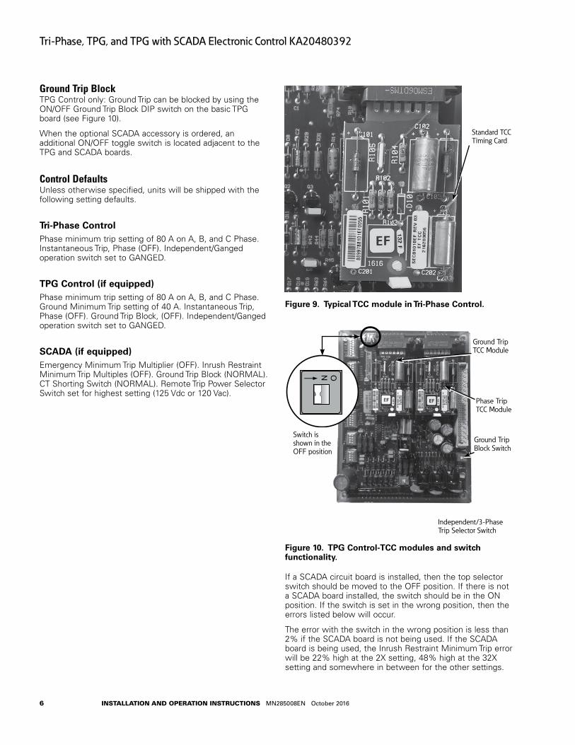
Standard TCC Timing Card
Figure 9 . Typical TCC module in Tri-Phase Control .
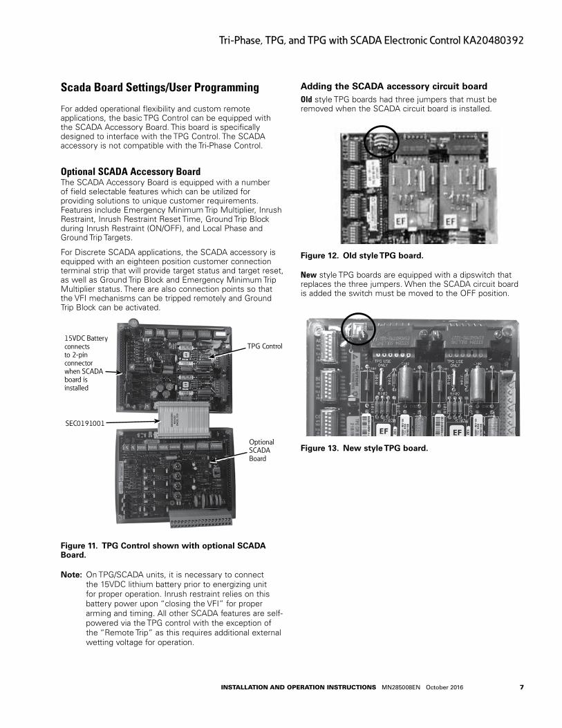
Ground Trip TCC Module
Switch is shown in the OFF position
Phase Trip TCC Module
Ground Trip Block Switch
Independent/3-Phase Trip Selector Switch
ON
Figure 10 . TPG Control-TCC modules and switch functionality .
If a SCADA circuit board is installed, then the top selector switch should be moved to the OFF position. If there is not a SCADA board installed, the switch should be in the ON position. If the switch is set in the wrong position, then the errors listed below will occur.
The error with the switch in the wrong position is less than 2% if the SCADA board is not being used. If the SCADA board is being used, the Inrush Restraint Minimum Trip error will be 22% high at the 2X setting, 48% high at the 32X setting and somewhere in between for the other settings.
7
Tri-Phase, TPG, and TPG with SCADA Electronic Control KA20480392
InstallatIon and operatIon InstructIons MN285008EN October 2016
Scada Board Settings/User Programming
For added operational flexibility and custom remote applications, the basic TPG Control can be equipped with the SCADA Accessory Board. This board is specifically designed to interface with the TPG Control. The SCADA accessory is not compatible with the Tri-Phase Control.
Optional SCADA Accessory BoardThe SCADA Accessory Board is equipped with a number of field selectable features which can be utilized for providing solutions to unique customer requirements. Features include Emergency Minimum Trip Multiplier, Inrush Restraint, Inrush Restraint Reset Time, Ground Trip Block during Inrush Restraint (ON/OFF), and Local Phase and Ground Trip Targets.
For Discrete SCADA applications, the SCADA accessory is equipped with an eighteen position customer connection terminal strip that will provide target status and target reset, as well as Ground Trip Block and Emergency Minimum Trip Multiplier status. There are also connection points so that the VFI mechanisms can be tripped remotely and Ground Trip Block can be activated.
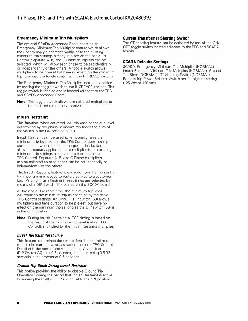
TPG Control
SEC0191001
15VDC Battery connects to 2-pin connector when SCADA board is installed
Optional SCADA Board
Figure 11 . TPG Control shown with optional SCADA Board .
otee:N On TPG/SCADA units, it is necessary to connect the 15VDC lithium battery prior to energizing unit for proper operation. Inrush restraint relies on this battery power upon “closing the VFI” for proper arming and timing. All other SCADA features are self-powered via the TPG control with the exception of the “Remote Trip” as this requires additional external wetting voltage for operation.
Adding the SCADA accessory circuit boardOld style TPG boards had three jumpers that must be removed when the SCADA circuit board is installed.
Figure 12 . Old style TPG board .
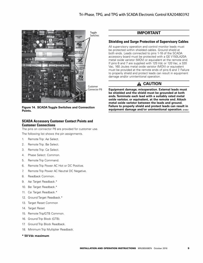
New style TPG boards are equipped with a dipswitch that replaces the three jumpers. When the SCADA circuit board is added the switch must be moved to the OFF position.
Figure 13 . New style TPG board .
8
Tri-Phase, TPG, and TPG with SCADA Electronic Control KA20480392
InstallatIon and operatIon InstructIons MN285008EN October 2016
Emergency Minimum Trip MultipliersThe optional SCADA Accessory Board contains an Emergency Minimum Trip Multiplier feature which allows the user to apply a constant multiplier to the existing minimum trip settings already in place on the basic TPG Control. Separate A, B, and C Phase multipliers can be selected, which will allow each phase to be set identically or independently of the others. A toggle switch allows multipliers to be pre-set but have no effect on the minimum trip, provided the toggle switch is in the NORMAL position.
The Emergency Minimum Trip Multiplier feature is enabled by moving the toggle switch to the INCREASE position. The toggle switch is labeled and is located adjacent to the TPG and SCADA Accessory Board.
otee:N The toggle switch allows pre-selected multipliers to be rendered temporarily inactive.
Inrush RestraintThis function, when activated, will trip each phase at a level determined by the phase minimum trip times the sum of the values in the ON position plus 1.
Inrush Restraint can be used to temporarily raise the minimum trip level so that the TPG Control does not trip due to inrush when load is re-energized. This feature allows temporary application of a multiplier to the existing minimum trip settings already in place on the basic TPG Control. Separate A, B, and C Phase multipliers can be selected so each phase can be set identically or independently of the others.
The Inrush Restraint feature is engaged from the moment a VFI mechanism is closed to restore service to a customer load. Varying Inrush Restraint reset times are selected by means of a DIP Switch (S4) located on the SCADA board.
At the end of the reset time, the minimum trip level will return to the minimum trip as specified by the basic TPG Control settings. An ON/OFF DIP switch (S8) allows multipliers and time duration to be pre-set, but have no effect on the minimum trip as long as the DIP switch (S8) is in the OFF position.
otee:N During Inrush Restraint, all TCC timing is based on the result of the minimum trip level (set on TPG Control), multiplied by the Inrush Restraint multiplier.
Inrush Restraint Reset TimeThis feature determines the time before the control returns to the minimum trip value, as set on the basic TPG Control. Duration is the sum of the values in the ON position (DIP Switch S4) plus 0.5 seconds, the range being 0.5-32 seconds in increments of 0.5 seconds.
Ground Trip Block During Inrush RestraintThis option provides the ability to disable Ground Trip Operations during the period that Inrush Restraint is active by moving the ON/OFF DIP switch S9 to the ON position.
Current Transformer Shorting SwitchThe CT shorting feature can be activated by use of the ON/OFF toggle switch located adjacent to the TPG and SCADA boards.
SCADA Defaults SettingsSCADA: Emergency Minimum Trip Multiplier (NORMAL) Inrush Restraint Minimum Trip Multiples (NORMAL). Ground Trip Block (NORMAL). CT Shorting Switch (NORMAL). Remote Trip Power Selector Switch set for highest setting (125 Vdc or 120 Vac).
9
Tri-Phase, TPG, and TPG with SCADA Electronic Control KA20480392
InstallatIon and operatIon InstructIons MN285008EN October 2016
Customer Connector P8
Toggle Switches
Figure 14 . SCADA Toggle Switches and Connection Points .
SCADA Accessory Customer Contact Points and Customer ConnectionsThe pins on connector P8 are provided for customer use.
The following list shows the pin assignments.
1. Remote Trip: Aø Select.
2. Remote Trip: Bø Select.
3. Remote Trip: Cø Select.
4. Phase Select: Common.
5. Remote Trip Command.
6. Remote Trip Power AC Hot or DC Positive.
7. Remote Trip Power AC Neutral DC Negative.
8. Readback Common.
9. Aø: Target Readback.*
10. Bø: Target Readback.*
11. Cø: Target Readback.*
12. Ground Target Readback.*
13. Target Reset Common
14. Target Reset
15. Remote Trip/GTB Common.
16. Ground Trip Block (GTB).
17. Ground Trip Block Readback.
18. Minimum Trip Multiplier Readback.
* 50 Vdc maximum
IMPORTANT
Shielding and Surge Protection of Supervisory CablesAll supervisory operation and control monitor leads must be protected within shielded cables. Ground shield at both ends. Leads connected to pins 1-18 of the SCADA accessory board must be protected with a GE V150LA20A metal oxide varistor (MOV) or equivalent at the remote end. If pins 6 and 7 are supplied with 125 Vdc or 120 Vac, a 320 Vac, 160 Joules metal oxide varistor (MOV) or equivalent must be provided at the remote ends of pins 6 and 7. Failure to properly shield and protect leads can result in equipment damage and/or unintentional operation.
CAUTIONEquipment damage; misoperation . External leads must be shielded and the shield must be grounded at both ends . Terminate each lead with a suitably rated metal oxide varistor, or equivalent, at the remote end . Attach metal oxide varistor between the leads and ground . Failure to properly shield and protect leads can result in equipment damage and/or unintentional operation . G139 .0
10
Tri-Phase, TPG, and TPG with SCADA Electronic Control KA20480392
InstallatIon and operatIon InstructIons MN285008EN October 2016
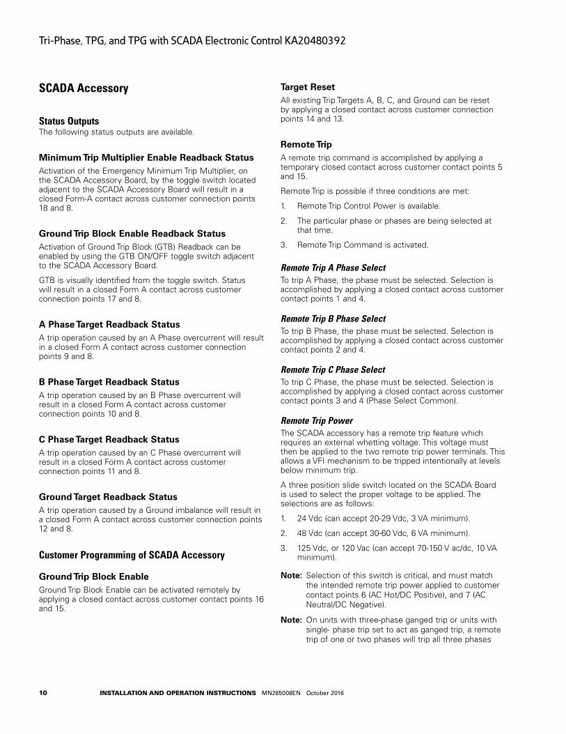
SCADA Accessory
Status OutputsThe following status outputs are available.
Minimum Trip Multiplier Enable Readback StatusActivation of the Emergency Minimum Trip Multiplier, on the SCADA Accessory Board, by the toggle switch located adjacent to the SCADA Accessory Board will result in a closed Form-A contact across customer connection points 18 and 8.
Ground Trip Block Enable Readback StatusActivation of Ground Trip Block (GTB) Readback can be enabled by using the GTB ON/OFF toggle switch adjacent to the SCADA Accessory Board.
GTB is visually identified from the toggle switch. Status will result in a closed Form A contact across customer connection points 17 and 8.
A Phase Target Readback StatusA trip operation caused by an A Phase overcurrent will result in a closed Form A contact across customer connection points 9 and 8.
B Phase Target Readback StatusA trip operation caused by an B Phase overcurrent will result in a closed Form A contact across customer connection points 10 and 8.
C Phase Target Readback StatusA trip operation caused by an C Phase overcurrent will result in a closed Form A contact across customer connection points 11 and 8.
Ground Target Readback StatusA trip operation caused by a Ground imbalance will result in a closed Form A contact across customer connection points 12 and 8.
Customer Programming of SCADA Accessory
Ground Trip Block EnableGround Trip Block Enable can be activated remotely by applying a closed contact across customer contact points 16 and 15.
Target ResetAll existing Trip Targets A, B, C, and Ground can be reset by applying a closed contact across customer connection points 14 and 13.
Remote TripA remote trip command is accomplished by applying a temporary closed contact across customer contact points 5 and 15.
Remote Trip is possible if three conditions are met:
1. Remote Trip Control Power is available.
2. The particular phase or phases are being selected at that time.
3. Remote Trip Command is activated.
Remote Trip A Phase SelectTo trip A Phase, the phase must be selected. Selection is accomplished by applying a closed contact across customer contact points 1 and 4.
Remote Trip B Phase SelectTo trip B Phase, the phase must be selected. Selection is accomplished by applying a closed contact across customer contact points 2 and 4.
Remote Trip C Phase SelectTo trip C Phase, the phase must be selected. Selection is accomplished by applying a closed contact across customer contact points 3 and 4 (Phase Select Common).
Remote Trip PowerThe SCADA accessory has a remote trip feature which requires an external whetting voltage. This voltage must then be applied to the two remote trip power terminals. This allows a VFI mechanism to be tripped intentionally at levels below minimum trip.
A three position slide switch located on the SCADA Board is used to select the proper voltage to be applied. The selections are as follows:
1. 24 Vdc (can accept 20-29 Vdc, 3 VA minimum).
2. 48 Vdc (can accept 30-60 Vdc, 6 VA minimum).
3. 125 Vdc, or 120 Vac (can accept 70-150 V ac/dc, 10 VA minimum).
otee:N Selection of this switch is critical, and must match the intended remote trip power applied to customer contact points 6 (AC Hot/DC Positive), and 7 (AC Neutral/DC Negative).
otee:N On units with three-phase ganged trip or units with single- phase trip set to act as ganged trip, a remote trip of one or two phases will trip all three phases
11
Tri-Phase, TPG, and TPG with SCADA Electronic Control KA20480392
InstallatIon and operatIon InstructIons MN285008EN October 2016
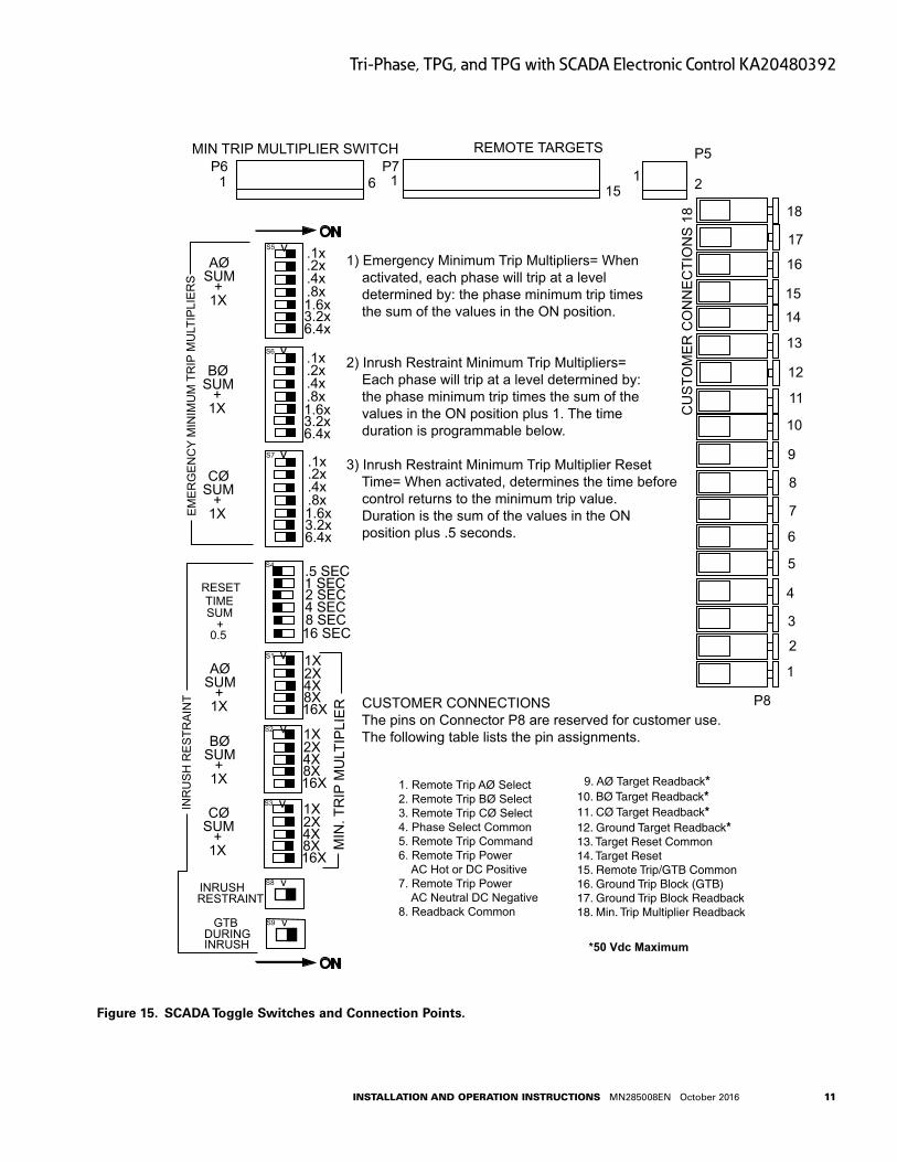
1) Emergency Minimum Trip Multipliers= When activated, each phase will trip at a level determined by: the phase minimum trip times the sum of the values in the ON position.
2) Inrush Restraint Minimum Trip Multipliers= Each phase will trip at a level determined by: the phase minimum trip times the sum of the values in the ON position plus 1. The time duration is programmable below.
3) Inrush Restraint Minimum Trip Multiplier ResetTime= When activated, determines the time before
control returns to the minimum trip value. Duration is the sum of the values in the ON position plus .5 seconds.
CUSTOMER CONNECTIONSThe pins on Connector P8 are reserved for customer use. The following table lists the pin assignments.
18
17
16
15
14
13
12
11
10
9
8
7
6
5
4
3
2
1C
US
TOM
ER
CO
NN
EC
TIO
NS
18
P5
2115
REMOTE TARGETSP7
16P6
1
MIN TRIP MULTIPLIER SWITCH
ON
ON
.4x
.1x
.2x
.8x1.6x3.2x6.4x
.4x
.1x
.2x
.8x1.6x3.2x6.4x
.4x
.1x
.2x
.8x1.6x3.2x6.4x
AØSUM
+1X
CØSUM
+1X
BØSUM
+1X
EM
ER
GE
NC
Y M
INIM
UM
TR
IP M
ULT
IPLI
ER
S
RESETTIMESUM
+0.5
AØSUM
+1X
BØSUM
+1X
CØSUM
+1X
INRUSHRESTRAINT
GTBDURINGINRUSH
INR
US
H R
ES
TRA
INT
1. Remote Trip AØ Select2. Remote Trip BØ Select3. Remote Trip CØ Select4. Phase Select Common5. Remote Trip Command6. Remote Trip Power
AC Hot or DC Positive7. Remote Trip Power
AC Neutral DC Negative8. Readback Common
9. AØ Target Readback*10. BØ Target Readback* 11. CØ Target Readback*12. Ground Target Readback*13. Target Reset Common14. Target Reset15. Remote Trip/GTB Common16. Ground Trip Block (GTB)17. Ground Trip Block Readback18. Min. Trip Multiplier Readback
MIN
. TR
IP M
ULT
IPLI
ER
.5 SEC1 SEC2 SEC4 SEC8 SEC16 SEC
1X2X4X8X16X
1X2X4X8X16X
1X2X4X8X16X
S5
S6
S7
S4
S1
S2
S3
v
v
v
v
v
v
S9 v
P8
*50 Vdc Maximum
S8 v
Figure 15 . SCADA Toggle Switches and Connection Points .
12
Tri-Phase, TPG, and TPG with SCADA Electronic Control KA20480392
InstallatIon and operatIon InstructIons MN285008EN October 2016
Installation Information
Controls necessary to operate Eaton’s Cooper Power series Type VFI padmounted switchgear (Tri-Phase, TPG, and TPG with SCADA Accessory) are pre-installed on the unit at the factory. On units equipped with top-hinged doors, the control( s) are mounted on the front plate(s). On units utilizing side-hinged doors, the controls are mounted on the doors.
Controls can be supplied for use with other switchgear or in optional cabinets to meet special application requirements. In this case, refer to installation drawings supplied with furnished control for correct installation procedures.
Controls are factory tested and ready for installation.
Verify all control settings prior to installation.
On TPG/SCADA units, it is necessary to connect the 15-volt lithium battery prior to energization.
otee:N Units equipped with TPG/SCADA are shipped with a 15-volt battery (shipped disconnected). Connect battery to connector on TPG board as shown in Figure 11.
The 15V battery is needed to operate the targets on the SCADA board, as well as provide the initial voltage needed to activate the Inrush Restraint functionality on the SCADA board. The battery also charges the trip capacitors on the TPG main board, reducing the arm time of the control when minimum trip is set to less than 40A, and the fault current is greater than 20x.
IMPORTANT
Shielding and Surge Protection of Supervisory CablesAll supervisory operation and control monitor leads must be protected within shielded cables. Ground shield at both ends. Leads connected to pins 1-18 of the SCADA accessory board must be protected with a GE V150LA20A metal oxide varistor (MOV) or equivalent at the remote end. If pins 6 and 7 are supplied with 125 Vdc or 120 Vac, a 320 Vac, 160 Joules metal oxide varistor (MOV) or equivalent must be provided at the remote ends of pins 6 and 7. Failure to properly shield and protect leads can result in equipment damage and/or unintentional operation.
CAUTIONEquipment damage; misoperation . External leads must be shielded and the shield must be grounded at both ends . Terminate each lead with a suitably rated metal oxide varistor, or equivalent, at the remote end . Attach metal oxide varistor between the leads and ground . Failure to properly shield and protect leads can result in equipment damage and/or unintentional operation . G139 .0
Testing Procedures
WARNINGHazardous voltage . The switchgear (apparatus and control) and high-voltage transformer must be in a test cage or similar protected area to prevent accidental contact with the high-voltage parts .
Solidly ground all equipment . Failure to comply can result in death, severe personal injury, and equipment damage . T221 .5
CAUTIONControl damage . De-energize both ac and dc power prior to removing or installing any internal connections or circuit boards in the control . Failure to comply can result in damage to the control . T241 .1
CAUTIONEquipment damage . Always wear a grounding wrist strap to control static electricity before handling circuit boards . Failure to use this strap may result in circuit board damage . T253 .1
Control RemovalTo remove control circuit board:
WARNINGThis equipment is not intended to protect human life . Follow all locally approved procedures and safety practices when installing or operating this equipment . Failure to comply can result in death, severe personal injury and equipment damage . G102 .1
1. De-energize switchgear (tap) by moving operating handle to the OPEN position.
2. Open the cabinet access cover.
otee:N An anti-static wrist device must be worn during this procedure.
3. Carefully disconnect VFI control cable from pin connector (P1), on Tri-Phase circuit board, and move connector out of the way.
4. Remove the four screws that secure circuit board to cabinet. Store the screws in a safe place for reuse. Carefully remove circuit board.
5. To reinstall, reverse procedure.
Functional TestingFunctional testing is done to verify proper operation of the control. For more information, refer to VFI Tester Manual S285-10-7.
13
Tri-Phase, TPG, and TPG with SCADA Electronic Control KA20480392
InstallatIon and operatIon InstructIons MN285008EN October 2016
Maintenance Procedures
WARNINGThis equipment requires routine inspection and maintenance to ensure proper operation . If it is not maintained it can fail to operate properly . Improper operation can cause equipment damage and possible personal injury . G105 .1
Replacement PartsOnly factory-authorized replacement parts are to be used for Eaton’s Cooper Power series products. Replacement parts are available through the factory Service Department. To order replacement parts, refer to the nameplate and provide the product type, serial number, catalog number, and voltage rating and a description of the parts. Contact your Eaton’s Cooper Power series product representative for additional information and ordering procedures.
Tri-phase (TP) control replacement parts:●● Encapsulated tri-phase main circuit board =
KSEC-701-7001
●● Standard TCC timing cards available for TP control as follows:
●● KVXE-702-F
●● KVXE-702-H
●● KVXE-702-EF
●● KVXE-702-KF
●● KVXE-702-TF
●● Minimum Response Time TCC curves available for TP control as follows:
●● KSEC-704-F
●● KSEC-704-H
●● KSEC-704-EF
●● KSEC-704-KF
●● KSEC-704-TF
New style Tri-phase with Ground (TPG) control replacement parts:
●● Encapsulated TPG main circuit board = KTPG-702-7003
●● Standard TCC timing cards available for TPG control as follows:
●● KSEC-704-1F
●● KSEC-704-1H
●● KSEC-704-1EF
●● KSEC-704-1KF
●● KSEC-704-1TF
●● Minimum Response Time TCC curves available for TPG control as follows:
●● KSEC-161-1 = Min Response EFR curve
●● KSEC-161-2 = Min Response FR curve
●● KSEC-161-3 = Min Response HR curve
●● KSEC-161-4 = Min response KFR curve
●● KSEC-161-5 = Min response TFR curve
New Style SCADA Accessory replacement parts (can only be used with TPG control):
●● Encapsulated SCADA board = KTPG-702-7005
●● Connecting harness = KTPG-702-7006
●● If want both New Style TPG board and New Style SCADA board including the connecting harness order = KTPG-702-7004
●● SCADA 15VDC Lithium Battery = KPA-1058-1
To add vent holes to either TP or TPG control boxes:●● Order kit = KP00300L00A87S
Repair ShopsFactory-authorized repair shops are located throughout the continental United States to provide maintenance, repair, and testing services for Eaton’s Cooper Power series padmount switchgear and reclosers. For further information, contact your Eaton’s Cooper Power series product representative.
Factory Maintenance ClassesThe factory Service Department offers maintenance training on all Cooper Power series equipment manufactured by Eaton. Classes are held at the factory’s in-house training facility and taught by experienced service technicians. For additional information, contact your Eaton’s Cooper Power series product representative.
Control BatteryThe battery equipped with the SCADA accessory is a lithium battery with a rated shelf life of six years.
It is not recommended or necessary to charge this battery.
CAUTIONFire . Explosion . Leakage . Severe burn hazard . Do not recharge or disassemble battery . Battery should not be exposed to temperatures above 175°F . Do not incinerate or expose the battery contents to water . Failure to comply can result in equipment damage and serious personal injury . T251 .1

14
Tri-Phase, TPG, and TPG with SCADA Electronic Control KA20480392
InstallatIon and operatIon InstructIons MN285008EN October 2016
his page is intentionally left blank.T

15
Tri-Phase, TPG, and TPG with SCADA Electronic Control KA20480392
InstallatIon and operatIon InstructIons MN285008EN October 2016
his page is intentionally left blank.T

Eaton1000 Eaton BoulevardCleveland, OH 44122United StatesEaton.com
Eaton’s Power Systems Division2300 Badger DriveWaukesha, WI 53188United StatesEaton.com/cooperpowerseries
© 2016 EatonAll Rights ReservedPrinted in USAPublication No. MN285008ENOctober 2016KA20480392 REV 05
Eaton is a registered trademark.
All trademarks are property of their respective owners.
For Eaton's Cooper Power series product information call 1-877-277-4636 or visit: www.eaton.com/cooperpowerseries.
!SAFETYFOR LIFE