
Effective mass of photons in one dimensional photonic crystal
TRH 11
Dimensional and Mass Limitations and
Other Requirements for Abnormal Load
Vehicles
8th Edition
March 2010
Revision 1
September 2014
COTOSouth Africa
Committee of Transport
Officials
COTOSouth Africa
Committee of Transport
Officials
ISBN 978-0-620-42786-9
Published in November 2013 by the
Department of Transport
Private Bag X193
PRETORIA
0001
REPUBLIC OF SOUTH AFRICA
The 8th Edition, published in March 2010 has been amended by the inclusion of Section 3.5.2.1,
dealing with the assessment of the impact of all terrain mobile cranes on bridges and culverts.
Earlier Editions:
First published in 1974
First revision in May 1979
Second revision March 1981
Reprinted in June 1982
Third revision April 1987
Fourth revision April 1992
Fifth revision November 1992
Sixth revision September 1997
Seventh revision March 2000
Eighth revision March 2010
Printed in the
Republic of South Africa
i
FOREWORD
The history of TRH 11 dates back to 1970, when a committee, the Committee on Abnormal
Loads, was formed comprising a team of traffic, road and structural engineers. This
committee was tasked to develop recommendations for the adoption of a uniform approach
to administer and govern the registration of abnormal vehicles and the conveyance of
abnormal loads in South Africa. Throughout its history, the document they developed,
generally known as TRH 11, remained under the care and development of this committee,
now known as the Abnormal Loads Technical Committee. The document has been updated
on a number of occasions on a needs basis to accommodate developments and trends in the
transportation industry and a stage was reached where there was general consensus that
the document needed a major revision. This latest version is the result of this major revision.
The objectives that were set for this latest revision of TRH 11 included the review of various
requirements and technical provisions and the simplification and clarification of the document
through the elimination of contradictions, ambiguities and duplications. In this latest revision,
the technical issues and the administrative issues have been rightfully separated. The
TRH 11 now focuses on technical issues, while a separate document, the Administrative
Guidelines for Granting of Exemption Permits for the Conveyance of Abnormal Loads, has
been developed. This latter document outlines the detailed procedures to follow when
applying to register and operate abnormal vehicles and includes the rules or conditions which
apply to the transporting of abnormal loads.
This latest revision process included comprehensive interaction with industry stakeholders
(consignees, consignors, hauliers, manufacturers, industry associations and interested
stakeholders/parties); as well as road and traffic authorities and I want to thank all those
individuals and organizations for their participation and for the valuable input given.
Now that these guidelines have been revised, I appeal to all officials involved with the
registering of abnormal vehicles and the issuing of exemption permits to apply these
guidelines in a uniform way and to consult and interact with their counterparts in other
provinces in order to achieve this
It was a great privilege to have worked with the team that developed this current version of
TRH 11 - Dimensional and Mass Limitations and Other Requirements for Abnormal Loads
and the Administrative Guidelines for Granting of Exemption Permits for the Conveyance of
Abnormal Loads.
Prasanth Mohan
Chairman: Abnormal Load Technical Committee
Director: Infrastructure Network Management
Department of Transport
ii
SYNOPSIS
The National Road Traffic Act (Act 93 of 1996) and the National Road Traffic Regulations,
2000 prescribe certain limitations on vehicle dimensions and axle and vehicle masses that a
vehicle using a public road must comply with. However, certain vehicles and loads cannot be
moved on public roads without exceeding the limitations in terms of the dimensions and/or
mass as prescribed. Where such a vehicle or load cannot be dismantled, without
disproportionate effort, expense or risk of damage, into units that can travel or be transported
legally, it is classified as an abnormal load and is allowed to travel on public roads under an
exemption permit issued in terms of Section 81 of the National Road Traffic Act.
In this document various types of abnormalities and abnormal load and vehicle
configurations are described. Abnormal load classification in terms of dimensions and mass
is presented and routes are categorised in terms of paved width and posted speed limit.
Dimensional and mass limitations for abnormal vehicles allowable under an exemption
permit are defined. Marking and escorting requirements and speed restrictions applicable to
abnormal vehicles are described. An overview of methods to estimate road pavement
damage by abnormal vehicles is given.
iii
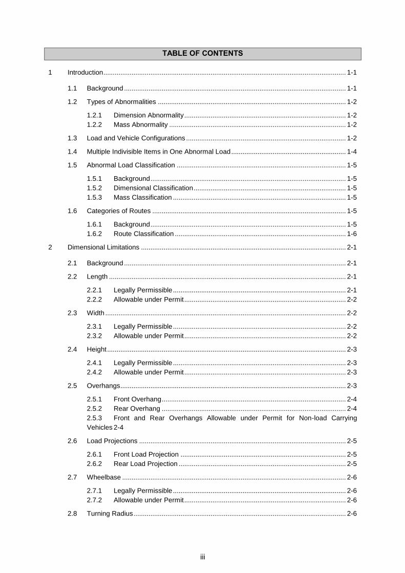
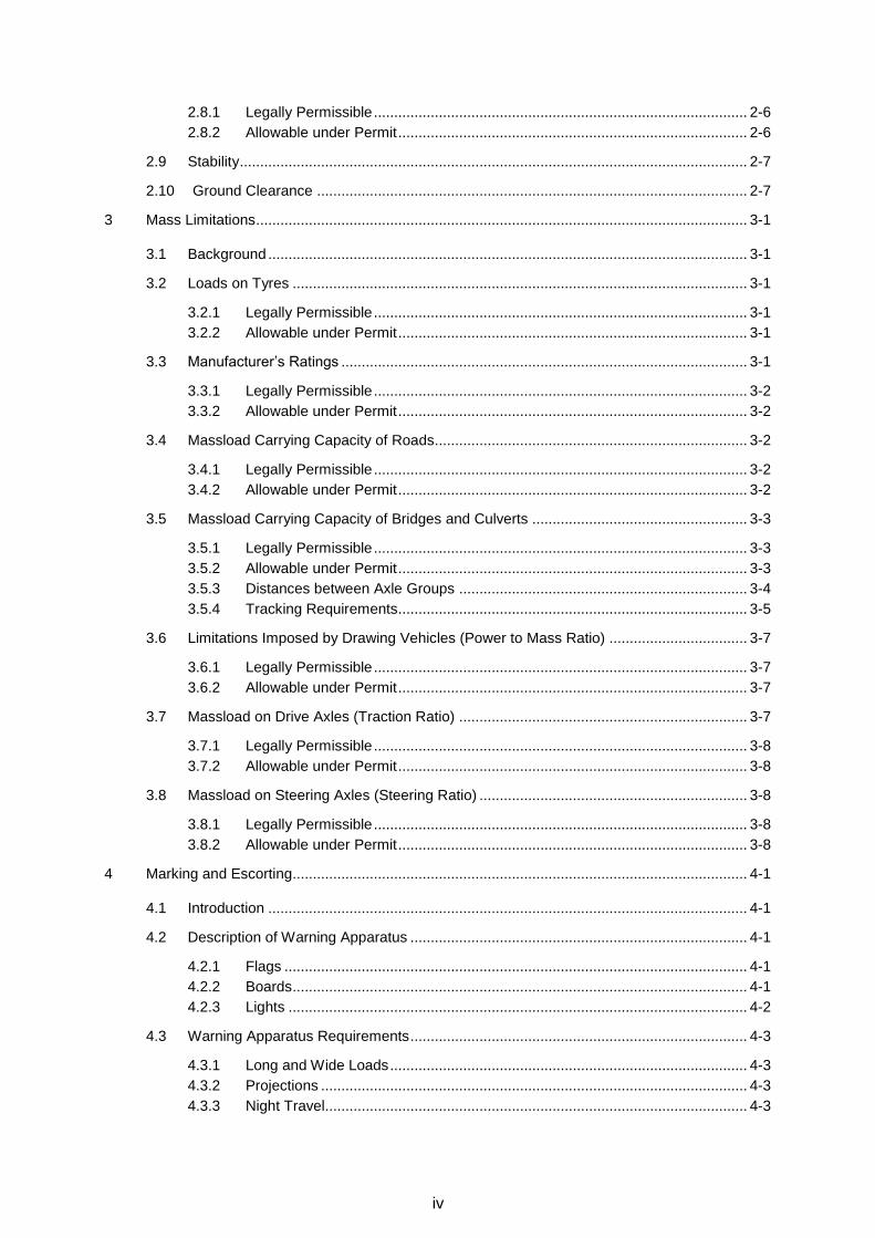
TABLE OF CONTENTS
1 Introduction ................................................................................................................................. 1-1
1.1 Background ...................................................................................................................... 1-1
1.2 Types of Abnormalities .................................................................................................... 1-2
1.2.1 Dimension Abnormality ...................................................................................... 1-2 1.2.2 Mass Abnormality .............................................................................................. 1-2
1.3 Load and Vehicle Configurations ..................................................................................... 1-2
1.4 Multiple Indivisible Items in One Abnormal Load ............................................................. 1-4
1.5 Abnormal Load Classification .......................................................................................... 1-5
1.5.1 Background ........................................................................................................ 1-5
1.5.2 Dimensional Classification ................................................................................. 1-5
1.5.3 Mass Classification ............................................................................................ 1-5
1.6 Categories of Routes ....................................................................................................... 1-5
1.6.1 Background ........................................................................................................ 1-5
1.6.2 Route Classification ........................................................................................... 1-6
2 Dimensional Limitations ............................................................................................................. 2-1
2.1 Background ...................................................................................................................... 2-1
2.2 Length .............................................................................................................................. 2-1
2.2.1 Legally Permissible ............................................................................................ 2-1 2.2.2 Allowable under Permit ...................................................................................... 2-2
2.3 Width ................................................................................................................................ 2-2
2.3.1 Legally Permissible ............................................................................................ 2-2
2.3.2 Allowable under Permit ...................................................................................... 2-2
2.4 Height ............................................................................................................................... 2-3
2.4.1 Legally Permissible ............................................................................................ 2-3
2.4.2 Allowable under Permit ...................................................................................... 2-3
2.5 Overhangs ........................................................................................................................ 2-3
2.5.1 Front Overhang .................................................................................................. 2-4 2.5.2 Rear Overhang .................................................................................................. 2-4 2.5.3 Front and Rear Overhangs Allowable under Permit for Non-load Carrying
Vehicles 2-4
2.6 Load Projections .............................................................................................................. 2-5
2.6.1 Front Load Projection ........................................................................................ 2-5 2.6.2 Rear Load Projection ......................................................................................... 2-5
2.7 Wheelbase ....................................................................................................................... 2-6
2.7.1 Legally Permissible ............................................................................................ 2-6 2.7.2 Allowable under Permit ...................................................................................... 2-6
2.8 Turning Radius ................................................................................................................. 2-6
iv
2.8.1 Legally Permissible ............................................................................................ 2-6
2.8.2 Allowable under Permit ...................................................................................... 2-6
2.9 Stability ............................................................................................................................. 2-7
2.10 Ground Clearance .......................................................................................................... 2-7
3 Mass Limitations ......................................................................................................................... 3-1
3.1 Background ...................................................................................................................... 3-1
3.2 Loads on Tyres ................................................................................................................ 3-1
3.2.1 Legally Permissible ............................................................................................ 3-1
3.2.2 Allowable under Permit ...................................................................................... 3-1
3.3 Manufacturer’s Ratings .................................................................................................... 3-1
3.3.1 Legally Permissible ............................................................................................ 3-2 3.3.2 Allowable under Permit ...................................................................................... 3-2
3.4 Massload Carrying Capacity of Roads............................................................................. 3-2
3.4.1 Legally Permissible ............................................................................................ 3-2
3.4.2 Allowable under Permit ...................................................................................... 3-2
3.5 Massload Carrying Capacity of Bridges and Culverts ..................................................... 3-3
3.5.1 Legally Permissible ............................................................................................ 3-3
3.5.2 Allowable under Permit ...................................................................................... 3-3 3.5.3 Distances between Axle Groups ....................................................................... 3-4
3.5.4 Tracking Requirements ...................................................................................... 3-5
3.6 Limitations Imposed by Drawing Vehicles (Power to Mass Ratio) .................................. 3-7
3.6.1 Legally Permissible ............................................................................................ 3-7 3.6.2 Allowable under Permit ...................................................................................... 3-7
3.7 Massload on Drive Axles (Traction Ratio) ....................................................................... 3-7
3.7.1 Legally Permissible ............................................................................................ 3-8 3.7.2 Allowable under Permit ...................................................................................... 3-8
3.8 Massload on Steering Axles (Steering Ratio) .................................................................. 3-8
3.8.1 Legally Permissible ............................................................................................ 3-8
3.8.2 Allowable under Permit ...................................................................................... 3-8
4 Marking and Escorting................................................................................................................ 4-1
4.1 Introduction ...................................................................................................................... 4-1
4.2 Description of Warning Apparatus ................................................................................... 4-1
4.2.1 Flags .................................................................................................................. 4-1
4.2.2 Boards ................................................................................................................ 4-1 4.2.3 Lights ................................................................................................................. 4-2
4.3 Warning Apparatus Requirements ................................................................................... 4-3
4.3.1 Long and Wide Loads ........................................................................................ 4-3 4.3.2 Projections ......................................................................................................... 4-3 4.3.3 Night Travel........................................................................................................ 4-3
v
4.3.4 Speed Restrictions ............................................................................................. 4-3
4.3.5 Warning Apparatus Prohibited ........................................................................... 4-3
4.4 Escorting of Abnormal Vehicles ....................................................................................... 4-4
4.4.1 Background ........................................................................................................ 4-4
4.4.2 Escort Classes ................................................................................................... 4-4 4.4.3 Escort Requirements ......................................................................................... 4-4
5 Speed Restrictions ..................................................................................................................... 5-1
5.1 Background ...................................................................................................................... 5-1
5.2 Tyre Loading .................................................................................................................... 5-1
5.3 Bridge Loading ................................................................................................................. 5-1
5.4 Dimensions ...................................................................................................................... 5-2
5.5 Mobile Cranes .................................................................................................................. 5-2
6 Estimation of Relative Road Pavement Damage by Abnormal Vehicles ................................... 6-1
6.1 Introduction ...................................................................................................................... 6-1
6.2 Equivalent Single Wheel Mass (ESWM) Method ............................................................. 6-1
6.3 South African Mechanistic-empirical Pavement Design Methodology (SAMDM) ........... 6-1
7 Technical Detail and Calculations .............................................................................................. 7-1
7.1 Introduction ...................................................................................................................... 7-1
7.2 Detailed Glossary ............................................................................................................. 7-1
7.2.1 5th Wheel ............................................................................................................ 7-1
7.2.2 Axle Configurations ............................................................................................ 7-1 7.2.3 Legal Axle Loads ............................................................................................... 7-2
7.3 Road Usage Factor (RUF) Calculation ............................................................................ 7-2
7.4 Effective Width Calculation .............................................................................................. 7-2
7.4.1 Effective Width of a Single Axle or Single Axle Group ...................................... 7-2 7.4.2 Weighted Effective Width Calculation ................................................................ 7-3
7.5 Tyre Pressure Calculation ................................................................................................ 7-4
8 References ................................................................................................................................. 8-1
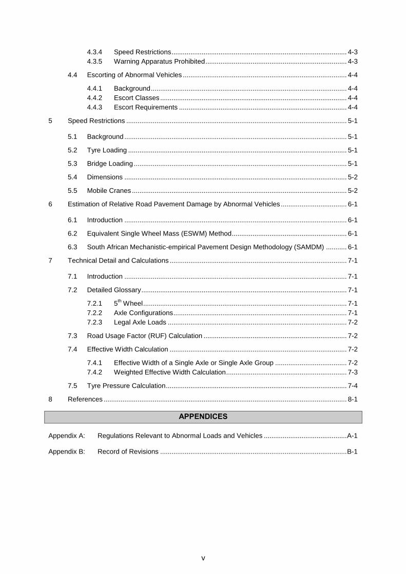
APPENDICES
Appendix A: Regulations Relevant to Abnormal Loads and Vehicles ............................................ A-1
Appendix B: Record of Revisions ................................................................................................... B-1
vi
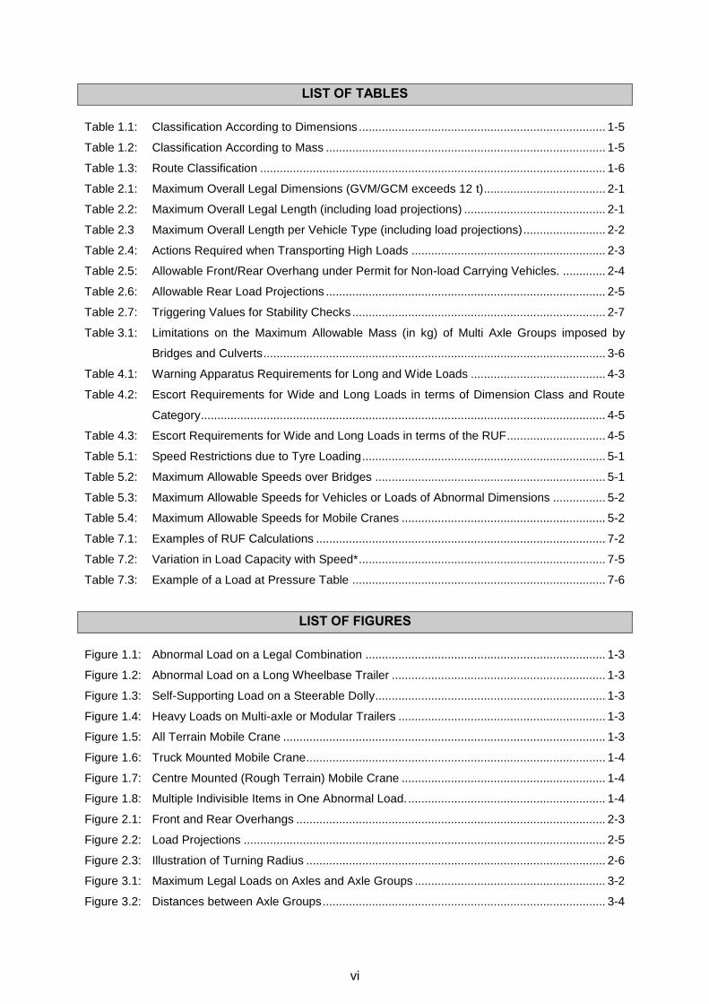
LIST OF TABLES
Table 1.1: Classification According to Dimensions ........................................................................... 1-5
Table 1.2: Classification According to Mass ..................................................................................... 1-5
Table 1.3: Route Classification ......................................................................................................... 1-6
Table 2.1: Maximum Overall Legal Dimensions (GVM/GCM exceeds 12 t) ..................................... 2-1
Table 2.2: Maximum Overall Legal Length (including load projections) ........................................... 2-1
Table 2.3 Maximum Overall Length per Vehicle Type (including load projections) ......................... 2-2
Table 2.4: Actions Required when Transporting High Loads ........................................................... 2-3
Table 2.5: Allowable Front/Rear Overhang under Permit for Non-load Carrying Vehicles. ............. 2-4
Table 2.6: Allowable Rear Load Projections ..................................................................................... 2-5
Table 2.7: Triggering Values for Stability Checks ............................................................................. 2-7
Table 3.1: Limitations on the Maximum Allowable Mass (in kg) of Multi Axle Groups imposed by
Bridges and Culverts ........................................................................................................ 3-6
Table 4.1: Warning Apparatus Requirements for Long and Wide Loads ......................................... 4-3
Table 4.2: Escort Requirements for Wide and Long Loads in terms of Dimension Class and Route
Category ........................................................................................................................... 4-5
Table 4.3: Escort Requirements for Wide and Long Loads in terms of the RUF.............................. 4-5
Table 5.1: Speed Restrictions due to Tyre Loading .......................................................................... 5-1
Table 5.2: Maximum Allowable Speeds over Bridges ...................................................................... 5-1
Table 5.3: Maximum Allowable Speeds for Vehicles or Loads of Abnormal Dimensions ................ 5-2
Table 5.4: Maximum Allowable Speeds for Mobile Cranes .............................................................. 5-2
Table 7.1: Examples of RUF Calculations ........................................................................................ 7-2
Table 7.2: Variation in Load Capacity with Speed* ........................................................................... 7-5
Table 7.3: Example of a Load at Pressure Table ............................................................................. 7-6
LIST OF FIGURES
Figure 1.1: Abnormal Load on a Legal Combination ......................................................................... 1-3
Figure 1.2: Abnormal Load on a Long Wheelbase Trailer ................................................................. 1-3
Figure 1.3: Self-Supporting Load on a Steerable Dolly ...................................................................... 1-3
Figure 1.4: Heavy Loads on Multi-axle or Modular Trailers ............................................................... 1-3
Figure 1.5: All Terrain Mobile Crane .................................................................................................. 1-3
Figure 1.6: Truck Mounted Mobile Crane ........................................................................................... 1-4
Figure 1.7: Centre Mounted (Rough Terrain) Mobile Crane .............................................................. 1-4
Figure 1.8: Multiple Indivisible Items in One Abnormal Load. ............................................................ 1-4
Figure 2.1: Front and Rear Overhangs .............................................................................................. 2-3
Figure 2.2: Load Projections .............................................................................................................. 2-5
Figure 2.3: Illustration of Turning Radius ........................................................................................... 2-6
Figure 3.1: Maximum Legal Loads on Axles and Axle Groups .......................................................... 3-2
Figure 3.2: Distances between Axle Groups ...................................................................................... 3-4
vii
Figure 4.1: Abnormal Vehicle Warning Board .................................................................................... 4-1
Figure 4.2: Escort Vehicle Warning Board ......................................................................................... 4-2
Figure 4.3: Speed Restriction Board .................................................................................................. 4-2
Figure 4.4: Warning Apparatus and Escort Requirements ................................................................ 4-7
Figure 7.1: 5th Wheel on Truck Tractor .............................................................................................. 7-1
Figure 7.2: Common Axle Configurations on Abnormal Vehicles ...................................................... 7-1
Figure 7.3: Legal Axle Loads in terms of Regulation 240 of the NRTR ............................................. 7-2
Figure 7.4: Illustration of Effective Width Calculation ......................................................................... 7-3
Figure 7.5: Example of ‘Weighted” Effective Width Calculation ......................................................... 7-3
Figure 7.6: 4-Axle unit with 4-Duals in-line ........................................................................................ 7-5

viii
DEFINITIONS
Term Definition See also
Abnormal load
An indivisible (for practical purposes) object that, due to its
dimensions and/or mass, cannot be transported on a vehicle or
vehicles without exceeding the limitations of the dimensions or
mass as described in the National Road Traffic Regulations, 2000.
1.1
Abnormal
vehicle
A vehicle or a combination of vehicles that, by virtue of its
dimensions or mass, or a combination of both, does not comply with
the requirements of the National Road Traffic Regulations, 2000.
In Regulation 284 of the NRTR an abnormal vehicle is defined as:
“Any vehicle which is operated under a written exemption granted in
terms of Section 81 of the Act and any motor vehicle accompanying
such abnormal vehicle as a condition for operation.”
1.1
Adapter dolly
(from NRTR)
A semi-trailer with one or more axles, designed or adapted –
(a) to be attached between a truck –tractor and semi-trailer, and
(b) not to carry any load other than that imposed by a semi-trailer.
Administrative
Officer
A person appointed by the carrier and who, as far as the abnormal
load or vehicle is concerned, is responsible for the conduct and
operations of the carrier to whom a permit has been granted.
Allowable
The maximum mass and dimensions, which the provincial
authorities will allow in terms of the Guidelines. “Allowed” shall have
a corresponding meaning.
Articulated
motor vehicle
(from NRTA)
A combination of motor vehicles consisting of a truck-tractor and a
semi-trailer.
Table 2.1
Sketch
AVR Number
A reference number which has been allocated to a vehicle, or a
combination of vehicles that has been entered in a Register of
Abnormal Vehicles approved by the Provincial Authorities.
Axle
(from NRTR)
In relation to a vehicle, means a device or set of devices, whether
continuous across the width of the vehicle or not, about which the
wheels of the vehicle rotate and which is so placed that, when the
vehicle is travelling straight ahead, the vertical centre-lines of such
wheels would be in one vertical plane at right angles to the
longitudinal centre-line of such vehicle.
Bridge
Any structure designed to carry vehicular traffic and which spans a
gap of more than 6 m. In terms of the NRTA, a bridge includes a
culvert and a causeway.
Carrier
In the context of this document means a person who undertakes the
conveyance of abnormal loads by road for reward or in the course
of his industry, trade or business by means of a motor vehicle.
Converter dolly
(from NRTR)
A trailer which has one or more axles and, when used in
combination with a semi-trailer, converts the semi- trailer into a
trailer.
ix
Term Definition See also
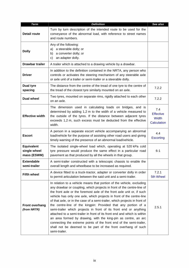
Detail route
Turn by turn description of the intended route to be used for the
conveyance of the abnormal load, with reference to street names
and route numbers.
Dolly
Any of the following:
a) a steerable dolly; or
b) a converter dolly; or
c) an adapter dolly.
Drawbar trailer A trailer which is attached to a drawing vehicle by a drawbar.
Driver
In addition to the definition contained in the NRTA, any person who
controls or activates the steering mechanism of any steerable axle
or axle unit of a trailer or semi-trailer or a steerable dolly.
Dual tyre
spacing
The distance from the centre of the tread of one tyre to the centre of
the tread of the closest tyre similarly mounted on an axle. 7.2.2
Dual wheel Two tyres, mounted on separate rims, rigidly attached to each other
on an axle. 7.2.2
Effective width
The dimension used in calculating loads on bridges, and is
determined by adding 1,2 m to the width of a vehicle measured to
the outside of the tyres. If the distance between adjacent tyres
exceeds 1,2 m, such excess must be deducted from the effective
width.
7.4
Effective
Width
Calculation
Escort
A person in a separate escort vehicle accompanying an abnormal
load/vehicle for the purpose of assisting other road users and giving
timely warning of the presence of an abnormal load/vehicle.
4.4
Escorting
Equivalent
single wheel
mass (ESWM)
The isolated single-wheel load which, operating at 520 kPa cold
tyre pressure would produce the same effect in a particular road
pavement as that produced by all the wheels in that group.
6-1
Extendable
semi-trailer
A semi-trailer constructed with a telescopic chassis to enable the
overall length and wheelbase to be increased as required.
Fifth wheel A device fitted to a truck-tractor, adapter or converter dolly in order
to permit articulation between the said unit and a semi-trailer.
7.2.1
5th Wheel
Front overhang
(from NRTR)
In relation to a vehicle means that portion of the vehicle, excluding
any drawbar or coupling, which projects in front of the centre-line of
the front axle or the foremost axle of the front axle unit or, if such
vehicle has only one axle, which projects in front of the centre-line
of that axle, or in the case of a semi-trailer, which projects in front of
the centre-line of the kingpin: Provided that any portion of a
semi-trailer which projects in front of its front end or anything
attached to a semi-trailer in front of its front end and which is within
an area formed by drawing, with the king-pin as centre, an arc
connecting the extreme points of the front end of the semi-trailer,
shall not be deemed to be part of the front overhang of such
semi-trailer.
2.5.1
x
Term Definition See also
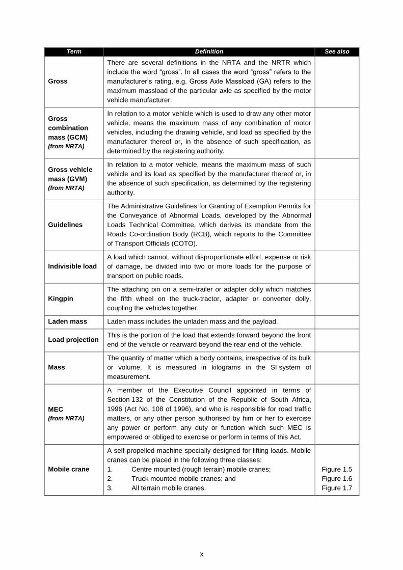
Gross
There are several definitions in the NRTA and the NRTR which
include the word “gross”. In all cases the word “gross” refers to the
manufacturer’s rating, e.g. Gross Axle Massload (GA) refers to the
maximum massload of the particular axle as specified by the motor
vehicle manufacturer.
Gross
combination
mass (GCM)
(from NRTA)
In relation to a motor vehicle which is used to draw any other motor
vehicle, means the maximum mass of any combination of motor
vehicles, including the drawing vehicle, and load as specified by the
manufacturer thereof or, in the absence of such specification, as
determined by the registering authority.
Gross vehicle
mass (GVM)
(from NRTA)
In relation to a motor vehicle, means the maximum mass of such
vehicle and its load as specified by the manufacturer thereof or, in
the absence of such specification, as determined by the registering
authority.
Guidelines
The Administrative Guidelines for Granting of Exemption Permits for
the Conveyance of Abnormal Loads, developed by the Abnormal
Loads Technical Committee, which derives its mandate from the
Roads Co-ordination Body (RCB), which reports to the Committee
of Transport Officials (COTO).
Indivisible load
A load which cannot, without disproportionate effort, expense or risk
of damage, be divided into two or more loads for the purpose of
transport on public roads.
Kingpin
The attaching pin on a semi-trailer or adapter dolly which matches
the fifth wheel on the truck-tractor, adapter or converter dolly,
coupling the vehicles together.
Laden mass Laden mass includes the unladen mass and the payload.
Load projection This is the portion of the load that extends forward beyond the front
end of the vehicle or rearward beyond the rear end of the vehicle.
Mass
The quantity of matter which a body contains, irrespective of its bulk
or volume. It is measured in kilograms in the SI system of
measurement.
MEC
(from NRTA)
A member of the Executive Council appointed in terms of
Section 132 of the Constitution of the Republic of South Africa,
1996 (Act No. 108 of 1996), and who is responsible for road traffic
matters, or any other person authorised by him or her to exercise
any power or perform any duty or function which such MEC is
empowered or obliged to exercise or perform in terms of this Act.
Mobile crane
A self-propelled machine specially designed for lifting loads. Mobile
cranes can be placed in the following three classes:
1. Centre mounted (rough terrain) mobile cranes;
2. Truck mounted mobile cranes; and
3. All terrain mobile cranes.
Figure 1.5
Figure 1.6
Figure 1.7
xi
Term Definition See also
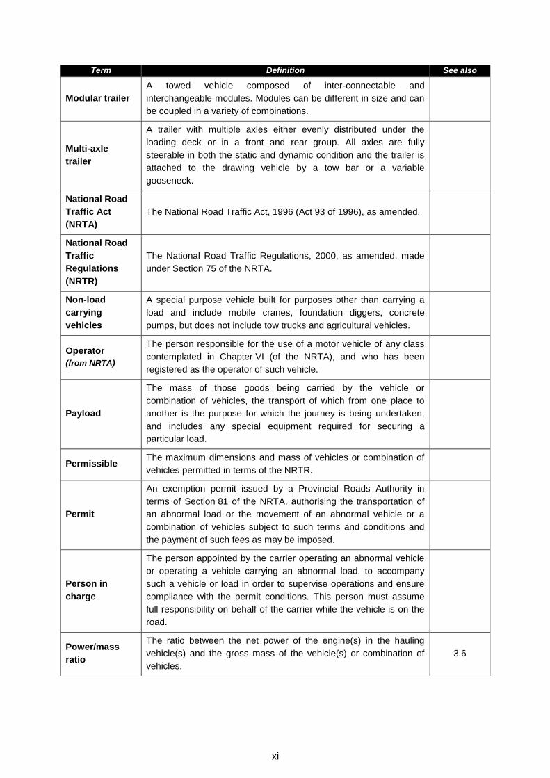
Modular trailer
A towed vehicle composed of inter-connectable and
interchangeable modules. Modules can be different in size and can
be coupled in a variety of combinations.
Multi-axle
trailer
A trailer with multiple axles either evenly distributed under the
loading deck or in a front and rear group. All axles are fully
steerable in both the static and dynamic condition and the trailer is
attached to the drawing vehicle by a tow bar or a variable
gooseneck.
National Road
Traffic Act
(NRTA)
The National Road Traffic Act, 1996 (Act 93 of 1996), as amended.
National Road
Traffic
Regulations
(NRTR)
The National Road Traffic Regulations, 2000, as amended, made
under Section 75 of the NRTA.
Non-load
carrying
vehicles
A special purpose vehicle built for purposes other than carrying a
load and include mobile cranes, foundation diggers, concrete
pumps, but does not include tow trucks and agricultural vehicles.
Operator
(from NRTA)
The person responsible for the use of a motor vehicle of any class
contemplated in Chapter VI (of the NRTA), and who has been
registered as the operator of such vehicle.
Payload
The mass of those goods being carried by the vehicle or
combination of vehicles, the transport of which from one place to
another is the purpose for which the journey is being undertaken,
and includes any special equipment required for securing a
particular load.
Permissible The maximum dimensions and mass of vehicles or combination of
vehicles permitted in terms of the NRTR.
Permit
An exemption permit issued by a Provincial Roads Authority in
terms of Section 81 of the NRTA, authorising the transportation of
an abnormal load or the movement of an abnormal vehicle or a
combination of vehicles subject to such terms and conditions and
the payment of such fees as may be imposed.
Person in
charge
The person appointed by the carrier operating an abnormal vehicle
or operating a vehicle carrying an abnormal load, to accompany
such a vehicle or load in order to supervise operations and ensure
compliance with the permit conditions. This person must assume
full responsibility on behalf of the carrier while the vehicle is on the
road.
Power/mass
ratio
The ratio between the net power of the engine(s) in the hauling
vehicle(s) and the gross mass of the vehicle(s) or combination of
vehicles.
3.6
xii
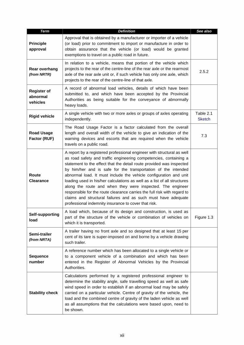
Term Definition See also
Principle
approval
Approval that is obtained by a manufacturer or importer of a vehicle
(or load) prior to commitment to import or manufacture in order to
obtain assurance that the vehicle (or load) would be granted
exemptions to travel on a public road in future.
Rear overhang
(from NRTR)
In relation to a vehicle, means that portion of the vehicle which
projects to the rear of the centre-line of the rear axle or the rearmost
axle of the rear axle unit or, if such vehicle has only one axle, which
projects to the rear of the centre-line of that axle.
2.5.2
Register of
abnormal
vehicles
A record of abnormal load vehicles, details of which have been
submitted to, and which have been accepted by the Provincial
Authorities as being suitable for the conveyance of abnormally
heavy loads.
Rigid vehicle A single vehicle with two or more axles or groups of axles operating
independently.
Table 2.1
Sketch
Road Usage
Factor (RUF)
The Road Usage Factor is a factor calculated from the overall
length and overall width of the vehicle to give an indication of the
warning devices and escorts that are required when the vehicle
travels on a public road.
7.3
Route
Clearance
A report by a registered professional engineer with structural as well
as road safety and traffic engineering competencies, containing a
statement to the effect that the detail route provided was inspected
by him/her and is safe for the transportation of the intended
abnormal load. It must include the vehicle configuration and unit
loading used in his/her calculations as well as a list of all structures
along the route and when they were inspected. The engineer
responsible for the route clearance carries the full risk with regard to
claims and structural failures and as such must have adequate
professional indemnity insurance to cover that risk.
Self-supporting
load
A load which, because of its design and construction, is used as
part of the structure of the vehicle or combination of vehicles on
which it is transported.
Figure 1.3
Semi-trailer
(from NRTA)
A trailer having no front axle and so designed that at least 15 per
cent of its tare is super-imposed on and borne by a vehicle drawing
such trailer.
Sequence
number
A reference number which has been allocated to a single vehicle or
to a component vehicle of a combination and which has been
entered in the Register of Abnormal Vehicles by the Provincial
Authorities.
Stability check
Calculations performed by a registered professional engineer to
determine the stability angle, safe travelling speed as well as safe
wind speed in order to establish if an abnormal load may be safely
carried on a particular vehicle. Centre of gravity of the vehicle, the
load and the combined centre of gravity of the laden vehicle as well
as all assumptions that the calculations were based upon, need to
be shown.
xiii
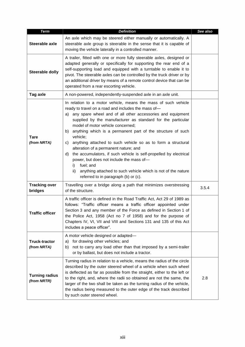
Term Definition See also
Steerable axle
An axle which may be steered either manually or automatically. A
steerable axle group is steerable in the sense that it is capable of
moving the vehicle laterally in a controlled manner.
Steerable dolly
A trailer, fitted with one or more fully steerable axles, designed or
adapted generally or specifically for supporting the rear end of a
self-supporting load and equipped with a turntable to enable it to
pivot. The steerable axles can be controlled by the truck driver or by
an additional driver by means of a remote control device that can be
operated from a rear escorting vehicle.
Tag axle A non-powered, independently-suspended axle in an axle unit.
Tare
(from NRTA)
In relation to a motor vehicle, means the mass of such vehicle
ready to travel on a road and includes the mass of—
a) any spare wheel and of all other accessories and equipment
supplied by the manufacturer as standard for the particular
model of motor vehicle concerned;
b) anything which is a permanent part of the structure of such
vehicle;
c) anything attached to such vehicle so as to form a structural
alteration of a permanent nature; and
d) the accumulators, if such vehicle is self-propelled by electrical
power, but does not include the mass of—
i) fuel; and
ii) anything attached to such vehicle which is not of the nature
referred to in paragraph (b) or (c).
Tracking over
bridges
Travelling over a bridge along a path that minimizes overstressing
of the structure. 3.5.4
Traffic officer
A traffic officer is defined in the Road Traffic Act, Act 29 of 1989 as
follows: “Traffic officer means a traffic officer appointed under
Section 3 and any member of the Force as defined in Section 1 of
the Police Act, 1958 (Act no 7 of 1958) and for the purpose of
Chapters IV, VI, VII and VIII and Sections 131 and 135 of this Act
includes a peace officer”.
Truck-tractor
(from NRTA)
A motor vehicle designed or adapted—
a) for drawing other vehicles; and
b) not to carry any load other than that imposed by a semi-trailer
or by ballast, but does not include a tractor.
Turning radius
(from NRTR)
Turning radius in relation to a vehicle, means the radius of the circle
described by the outer steered wheel of a vehicle when such wheel
is deflected as far as possible from the straight, either to the left or
to the right, and, where the radii so obtained are not the same, the
larger of the two shall be taken as the turning radius of the vehicle,
the radius being measured to the outer edge of the track described
by such outer steered wheel.
2.8
xiv
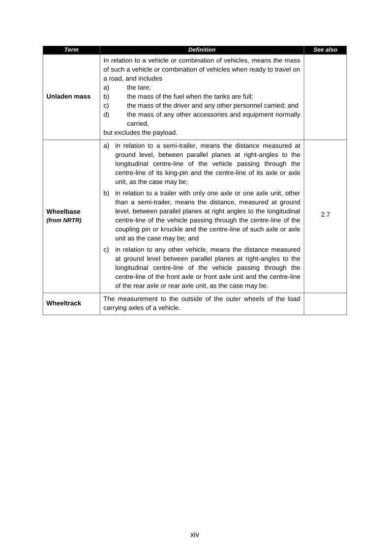
Term Definition See also
Unladen mass
In relation to a vehicle or combination of vehicles, means the mass
of such a vehicle or combination of vehicles when ready to travel on
a road, and includes
a) the tare;
b) the mass of the fuel when the tanks are full;
c) the mass of the driver and any other personnel carried; and
d) the mass of any other accessories and equipment normally
carried,
but excludes the payload.
Wheelbase
(from NRTR)
a) in relation to a semi-trailer, means the distance measured at
ground level, between parallel planes at right-angles to the
longitudinal centre-line of the vehicle passing through the
centre-line of its king-pin and the centre-line of its axle or axle
unit, as the case may be;
b) in relation to a trailer with only one axle or one axle unit, other
than a semi-trailer, means the distance, measured at ground
level, between parallel planes at right angles to the longitudinal
centre-line of the vehicle passing through the centre-line of the
coupling pin or knuckle and the centre-line of such axle or axle
unit as the case may be; and
c) in relation to any other vehicle, means the distance measured
at ground level between parallel planes at right-angles to the
longitudinal centre-line of the vehicle passing through the
centre-line of the front axle or front axle unit and the centre-line
of the rear axle or rear axle unit, as the case may be.
2.7
Wheeltrack The measurement to the outside of the outer wheels of the load
carrying axles of a vehicle.
TRH 11 Dimensional and Mass Limitations and Other Requirements for Abnormal Load Vehicles
8thRevision Pretoria 2010
1-1
1 INTRODUCTION
1.1 Background
The National Road Traffic Act (Act 93 of 1996) (herein referred to as the NRTA) and the
National Road Traffic Regulations, 2000 (herein after referred to as the NRTR), prescribe
certain limitations on vehicle dimensions and axle and vehicle masses with which a vehicle
using a public road must comply. However, certain vehicles and loads cannot be moved on
public roads without exceeding the limitations in terms of the dimensions and/or mass as
prescribed in the NRTR. Where such a vehicle or load cannot be dismantled without
disproportionate effort, expense or risk of damage into units that can travel or be transported
legally, it is classified as an abnormal load. Provision for such abnormal vehicles and loads is
made in Section 811 of the NRTA, which reads as follows:
‘‘Vehicle and load may be exempted from provisions of Act
81. (1) The Minister may, after the applicant has paid the fees or charges referred to in
Section 7(3) and subject to such conditions as he or she may determine, authorise in
writing, either generally or specifically, the operation on a public road of a vehicle which,
due to such vehicle’s original design cannot comply with this Act.
(2) The MEC may, after the applicant has paid the fees or charges referred to in
Section 7(3) and subject to such conditions as he or she may determine, authorise in
writing, either generally or specifically, the conveyance in a safe manner on a public road
of passengers or any load otherwise than in accordance with this Act.
(3) An MEC shall determine the fees or charges payable for a vehicle or load that does
not comply with this Act.’’
When the movement of an abnormal load is considered to be in the economic and/or social
interest of the country, an exemption permit may be issued to allow a vehicle(s) transporting
such an abnormal load to operate on a public road for a limited period.
Exemption permits are issued by provincial permit offices in terms of guidelines developed by
the Abnormal Loads Technical Committee (ALTC).
Abnormal vehicles, whether in terms of dimensions and/or mass, operate outside the criteria
used for the geometrical and structural design of road infrastructure. An abnormal vehicle
operating on the road therefore creates additional risks in terms of damage to the road
infrastructure and the safety of other road users. Road authorities have to assess these risks,
put measures in place to minimize the identified risks and ensure that they are properly
managed.
The purpose of this document is to assist road authorities and carriers to assess and minimize
the risks created through the movement of abnormal vehicles on the road network.
The fundamental principles guiding this process are:
1 As substituted by Section 23 of Act 64 of 2008: National Road Traffic Amendment Act, 2008.
TRH 11 Dimensional and Mass Limitations and Other Requirements for Abnormal Load Vehicles
8thRevision Pretoria 2010
1-2
An exemption permit for an abnormal load will only be considered for an indivisible load,
abnormal in dimension and/or mass, where there is no possibility of transporting the load in
a legal manner;
The damage to the road infrastructure by an abnormal vehicle has to be recovered from
the carrier;
The risks to other road users must be reduced to a level equivalent to a situation without
the presence of the abnormal vehicle on the road; and
The conditions imposed must take into account the economic and/or social interest of the
country and public at large.
The purpose of the exemption permit system is not to undermine or circumvent the NRTA
and the NRTR.
This document contains recommendations that are generally applicable, but the issuing
authority can deviate from these recommendations and/or impose additional requirements
when taking the circumstances applicable to each application into account.
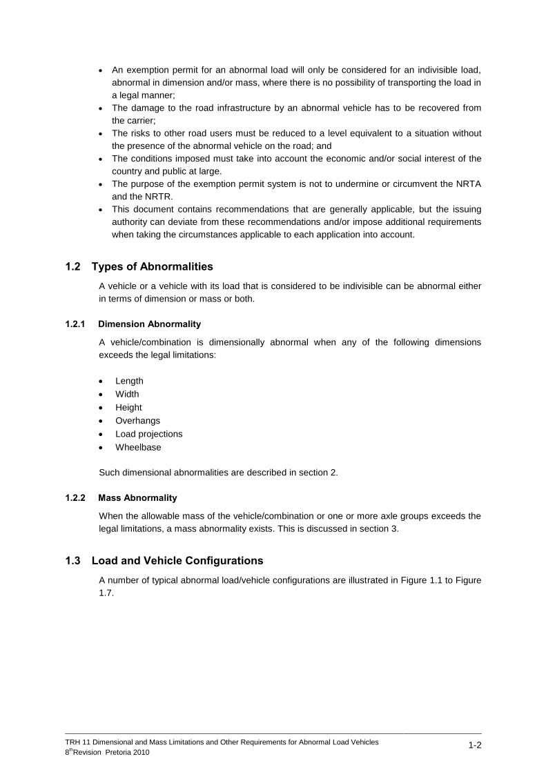
1.2 Types of Abnormalities
A vehicle or a vehicle with its load that is considered to be indivisible can be abnormal either
in terms of dimension or mass or both.
1.2.1 Dimension Abnormality
A vehicle/combination is dimensionally abnormal when any of the following dimensions
exceeds the legal limitations:
Length
Width
Height
Overhangs
Load projections
Wheelbase
Such dimensional abnormalities are described in section 2.
1.2.2 Mass Abnormality
When the allowable mass of the vehicle/combination or one or more axle groups exceeds the
legal limitations, a mass abnormality exists. This is discussed in section 3.
1.3 Load and Vehicle Configurations
A number of typical abnormal load/vehicle configurations are illustrated in Figure 1.1 to Figure
1.7.
TRH 11 Dimensional and Mass Limitations and Other Requirements for Abnormal Load Vehicles
8thRevision Pretoria 2010
1-3
Figure 1.1: Abnormal Load on a Legal Combination
Figure 1.2: Abnormal Load on a Long Wheelbase Trailer
Figure 1.3: Self-Supporting Load on a Steerable Dolly
Figure 1.4: Heavy Loads on Multi-axle or Modular Trailers
Figure 1.5: All Terrain Mobile Crane
18,5m2,6 m
END VIEW
ABNORMAL 4,3
m
10,0m
Wheelbase >10,0 m and ≤ 14,5 m
Self-supporting load Steerable dolly
Ballast Ballast
TRH 11 Dimensional and Mass Limitations and Other Requirements for Abnormal Load Vehicles
8thRevision Pretoria 2010
1-4
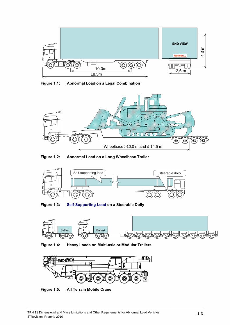
Figure 1.6: Truck Mounted Mobile Crane
Figure 1.7: Centre Mounted (Rough Terrain) Mobile Crane
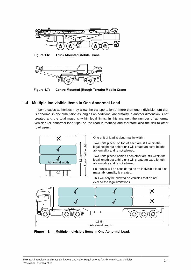
1.4 Multiple Indivisible Items in One Abnormal Load
In some cases authorities may allow the transportation of more than one indivisible item that
is abnormal in one dimension as long as an additional abnormality in another dimension is not
created and the total mass is within legal limits. In this manner, the number of abnormal
vehicles (or abnormal load trips) on the road is reduced and therefore also the risk to other
road users.
Figure 1.8: Multiple Indivisible Items in One Abnormal Load.
18,5 m
One unit of load is abnormal in width.
Two units placed on top of each are still within the
legal height but a third unit will create an extra height
abnormality and is not allowed.
Two units placed behind each other are still within the
legal length but a third unit will create an extra length
abnormality and is not allowed.
Four units will be considered as an indivisible load if no
mass abnormality is created.
This will only be allowed on vehicles that do not
exceed the legal limitations.
4,3
m
Abnormal length
Ab
no
rma
l h
eig
ht
Abnormal width
TRH 11 Dimensional and Mass Limitations and Other Requirements for Abnormal Load Vehicles
8thRevision Pretoria 2010
1-5
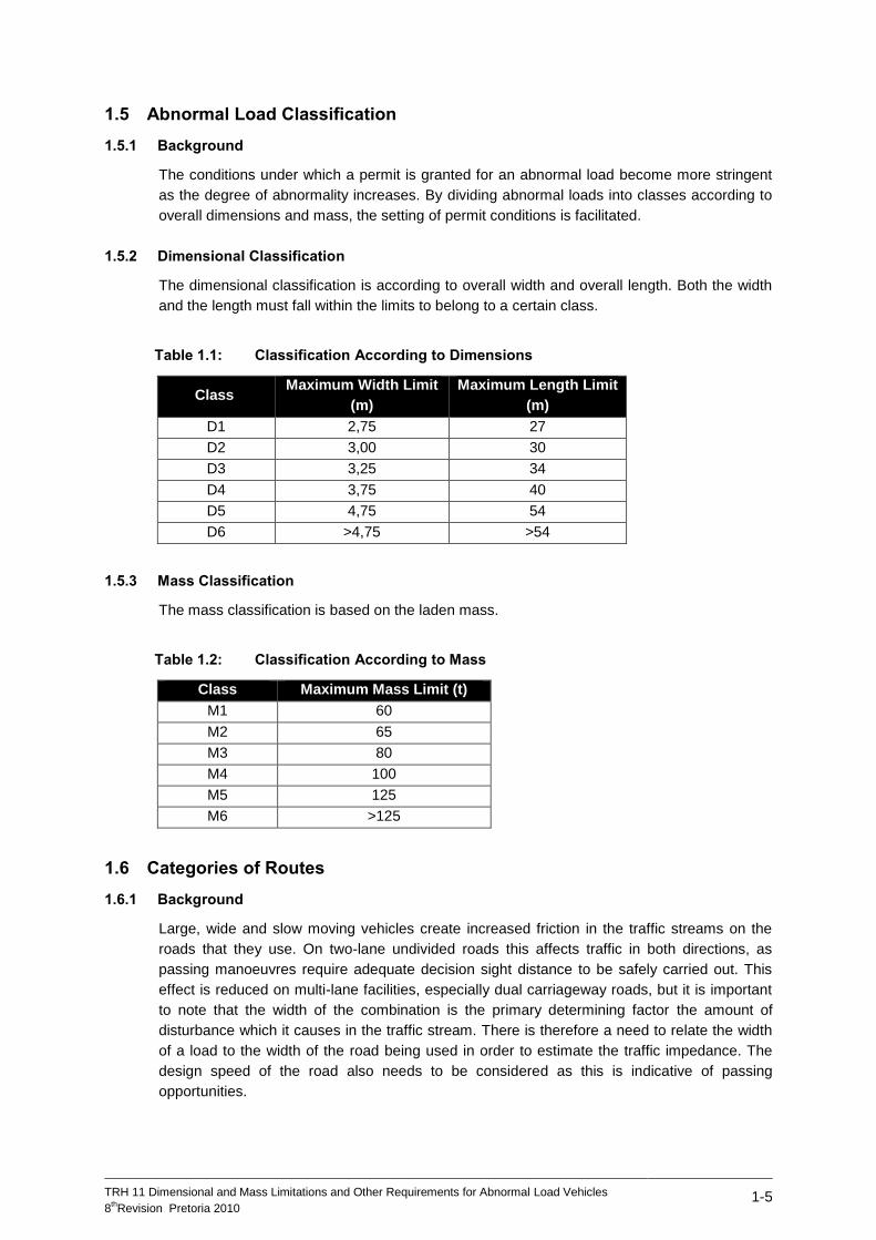
1.5 Abnormal Load Classification
1.5.1 Background
The conditions under which a permit is granted for an abnormal load become more stringent
as the degree of abnormality increases. By dividing abnormal loads into classes according to
overall dimensions and mass, the setting of permit conditions is facilitated.
1.5.2 Dimensional Classification
The dimensional classification is according to overall width and overall length. Both the width
and the length must fall within the limits to belong to a certain class.
Table 1.1: Classification According to Dimensions
Class Maximum Width Limit
(m)
Maximum Length Limit
(m)
D1 2,75 27
D2 3,00 30
D3 3,25 34
D4 3,75 40
D5 4,75 54
D6 >4,75 >54
1.5.3 Mass Classification
The mass classification is based on the laden mass.
Table 1.2: Classification According to Mass
Class Maximum Mass Limit (t)
M1 60
M2 65
M3 80
M4 100
M5 125
M6 >125
1.6 Categories of Routes
1.6.1 Background
Large, wide and slow moving vehicles create increased friction in the traffic streams on the
roads that they use. On two-lane undivided roads this affects traffic in both directions, as
passing manoeuvres require adequate decision sight distance to be safely carried out. This
effect is reduced on multi-lane facilities, especially dual carriageway roads, but it is important
to note that the width of the combination is the primary determining factor the amount of
disturbance which it causes in the traffic stream. There is therefore a need to relate the width
of a load to the width of the road being used in order to estimate the traffic impedance. The
design speed of the road also needs to be considered as this is indicative of passing
opportunities.
TRH 11 Dimensional and Mass Limitations and Other Requirements for Abnormal Load Vehicles
8thRevision Pretoria 2010
1-6
Sections of road are therefore classified in terms of two parameters that are a function of the
design standards. These parameters are the paved width and the posted speed limit. A speed
limit of 100 km/h or more would ensure adequate sight distance for safe overtaking of
abnormal load vehicles on two-way roads.
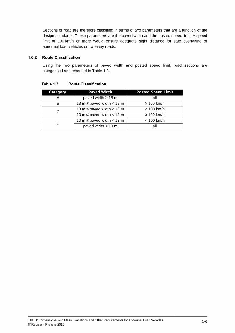
1.6.2 Route Classification
Using the two parameters of paved width and posted speed limit, road sections are
categorised as presented in Table 1.3.
Table 1.3: Route Classification
Category Paved Width Posted Speed Limit
A paved width ≥ 18 m all
B 13 m ≤ paved width < 18 m ≥ 100 km/h
C 13 m ≤ paved width < 18 m < 100 km/h
10 m ≤ paved width < 13 m ≥ 100 km/h
D 10 m ≤ paved width < 13 m < 100 km/h
paved width < 10 m all
TRH 11 Dimensional and Mass Limitations and Other Requirements for Abnormal Load Vehicles
8thRevision Pretoria 2010
2-1
2 DIMENSIONAL LIMITATIONS
2.1 Background
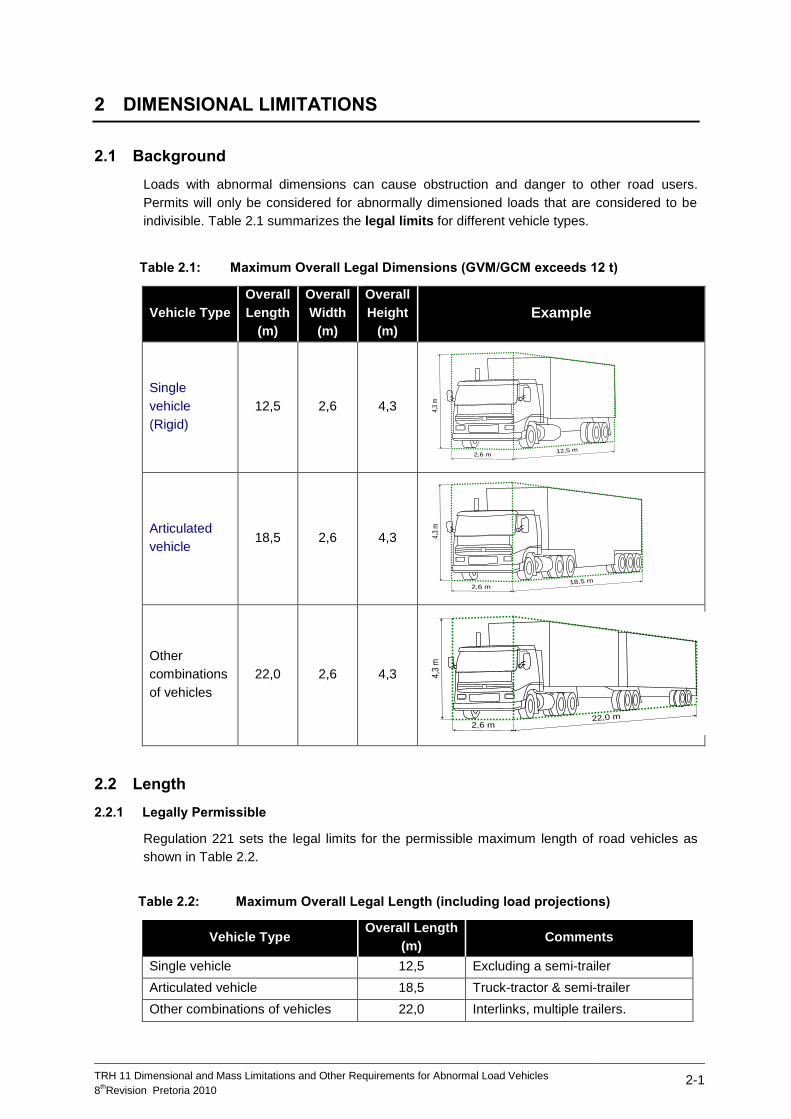
Loads with abnormal dimensions can cause obstruction and danger to other road users.
Permits will only be considered for abnormally dimensioned loads that are considered to be
indivisible. Table 2.1 summarizes the legal limits for different vehicle types.
Table 2.1: Maximum Overall Legal Dimensions (GVM/GCM exceeds 12 t)
Vehicle Type
Overall
Length
(m)
Overall
Width
(m)
Overall
Height
(m)
Example
Single
vehicle
(Rigid)
12,5 2,6 4,3
Articulated
vehicle 18,5 2,6 4,3
Other
combinations
of vehicles
22,0 2,6 4,3
2.2 Length
2.2.1 Legally Permissible
Regulation 221 sets the legal limits for the permissible maximum length of road vehicles as
shown in Table 2.2.
Table 2.2: Maximum Overall Legal Length (including load projections)
Vehicle Type Overall Length
(m) Comments
Single vehicle 12,5 Excluding a semi-trailer
Articulated vehicle 18,5 Truck-tractor & semi-trailer
Other combinations of vehicles 22,0 Interlinks, multiple trailers.
4,3
m
2,6 m12,5 m
2,6 m18,5 m
4,3
m
2,6 m22,0 m
4,3
m
TRH 11 Dimensional and Mass Limitations and Other Requirements for Abnormal Load Vehicles
8thRevision Pretoria 2010
2-2
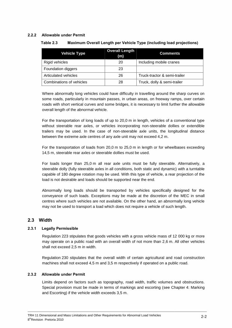
2.2.2 Allowable under Permit
Table 2.3 Maximum Overall Length per Vehicle Type (including load projections)
Vehicle Type Overall Length
(m) Comments
Rigid vehicles 20 Including mobile cranes
Foundation diggers 23
Articulated vehicles 26 Truck-tractor & semi-trailer
Combinations of vehicles 28 Truck, dolly & semi-trailer
Where abnormally long vehicles could have difficulty in travelling around the sharp curves on
some roads, particularly in mountain passes, in urban areas, on freeway ramps, over certain
roads with short vertical curves and some bridges, it is necessary to limit further the allowable
overall length of the abnormal vehicle.
For the transportation of long loads of up to 20,0 m in length, vehicles of a conventional type
without steerable rear axles, or vehicles incorporating non-steerable dollies or extendible
trailers may be used. In the case of non-steerable axle units, the longitudinal distance
between the extreme axle centres of any axle unit may not exceed 4,2 m.
For the transportation of loads from 20,0 m to 25,0 m in length or for wheelbases exceeding
14,5 m, steerable rear axles or steerable dollies must be used.
For loads longer than 25,0 m all rear axle units must be fully steerable. Alternatively, a
steerable dolly (fully steerable axles in all conditions, both static and dynamic) with a turntable
capable of 180 degree rotation may be used. With this type of vehicle, a rear projection of the
load is not desirable and loads should be supported near the end.
Abnormally long loads should be transported by vehicles specifically designed for the
conveyance of such loads. Exceptions may be made at the discretion of the MEC in small
centres where such vehicles are not available. On the other hand, an abnormally long vehicle
may not be used to transport a load which does not require a vehicle of such length.
2.3 Width
2.3.1 Legally Permissible
Regulation 223 stipulates that goods vehicles with a gross vehicle mass of 12 000 kg or more
may operate on a public road with an overall width of not more than 2,6 m. All other vehicles
shall not exceed 2,5 m in width.
Regulation 230 stipulates that the overall width of certain agricultural and road construction
machines shall not exceed 4,5 m and 3,5 m respectively if operated on a public road.
2.3.2 Allowable under Permit
Limits depend on factors such as topography, road width, traffic volumes and obstructions.
Special provision must be made in terms of markings and escorting (see Chapter 4: Marking
and Escorting) if the vehicle width exceeds 3,5 m.
TRH 11 Dimensional and Mass Limitations and Other Requirements for Abnormal Load Vehicles
8thRevision Pretoria 2010
2-3
2.4 Height
2.4.1 Legally Permissible
Regulation 224 sets a limit of 4,3 m on the overall height of a road vehicle, together with its
load, measured from ground level.
2.4.2 Allowable under Permit
The principal factors limiting the permissible height of abnormal loads are the clearances
under any overhead bridges or overhead lines on the route, and the stability of the vehicle and
the load. It is the responsibility of the carrier to identify a suitable route and to substantiate the
suitability of the route with the application.
Table 2.4: Actions Required when Transporting High Loads
Height Action
> 4,3 m
The clearance of every overhead obstruction must be established by the
carrier before the vehicle passes under it. (Note that the clearance under a
transmission line is not simply the clearance between the conductor and
the ground, but that a safety factor should be allowed for, depending on the
voltage).
> 4,7 m
A vehicle shall be provided to drive ahead of the abnormal vehicle. A gauge
of non-conducting material shall be fitted to the top of this vehicle. The
height of the gauge shall be 100 mm higher than the highest point of the
abnormal vehicle or load. It is also required of the carrier to give a written
confirmation that he knows the particular route and has recently gone
through it and should any structural damage occur he will then be held
responsible for any financial implications that have resulted.
> 5,5 m Permission must be obtained from Telkom prior to applying for a permit,
unless a lower limit is specified by Telkom for a specific area or route.
> 5,8 m Permission must be obtained from Eskom prior to applying for a permit,
unless a lower limit is specified by Eskom for a specific area or route.
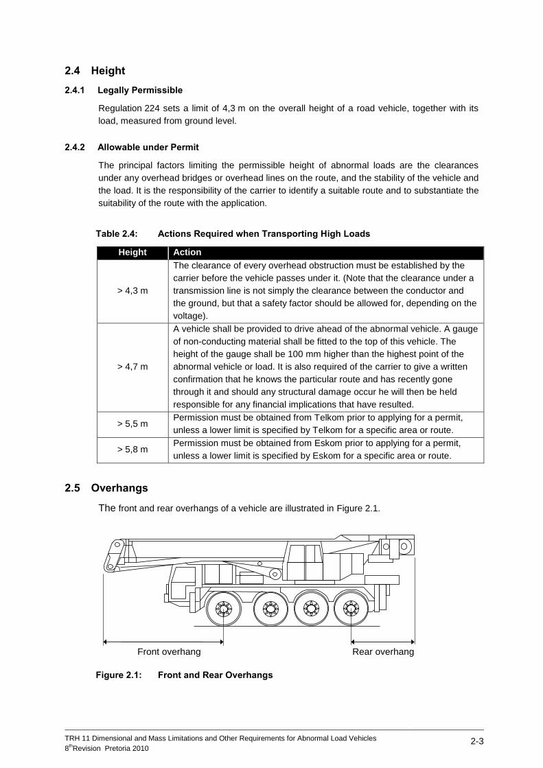
2.5 Overhangs
The front and rear overhangs of a vehicle are illustrated in Figure 2.1.
Figure 2.1: Front and Rear Overhangs
Front overhang Rear overhang

TRH 11 Dimensional and Mass Limitations and Other Requirements for Abnormal Load Vehicles
8thRevision Pretoria 2010
2-4
2.5.1 Front Overhang
2.5.1.1 Legally Permissible
Regulation 226 limits the front overhang of a vehicle as follows:
i) For vehicles where the distance from the front end of the vehicle to the backrest of the
driver's seat at seat-level is less than 1,7 m, to the lesser of –
60 per cent of the wheelbase, or
6,2 m less half the wheelbase.
ii) Where this distance is more than 1,7 m, to the lesser of –
60 per cent of the wheelbase, or
5,8 m less half the wheelbase.
iii) To 1,8 m for a semi-trailer.
2.5.1.2 Allowable under Permit
Load carrying abnormal vehicles must comply with the requirements of Regulation 226. For
non-load carrying vehicles, refer to section 2.5.3.
2.5.2 Rear Overhang
2.5.2.1 Legally Permissible
Regulation 226 limits the rear overhang of goods vehicles, measured from the rearmost axle,
to 60 per cent of the wheelbase.
2.5.2.2 Allowable under Permit
The rear overhang of a load carrying abnormal vehicle, measured from the rearmost axle,
may not exceed 2 m or 70 per cent of the wheelbase, whichever is the greater, subject to the
restriction on load projection stipulated in section 2.6. For non-load carrying vehicles, refer to
section 2.5.3.
2.5.3 Front and Rear Overhangs Allowable under Permit for Non-load Carrying Vehicles
In the case of non-load carrying vehicles, such as mobile cranes and foundation diggers, the
actual front or rear overhang shall not exceed the values given in Table 2.5. The overhang is
measured from the centre of the foremost or rearmost axle to the furthest point of the
overhang section of the vehicle.
Table 2.5: Allowable Front/Rear Overhang under Permit for Non-load Carrying
Vehicles.
Wheelbase (m) 3 m 4 m 5 m
6 m or more
Allowable front or rear overhang* 3,9 4,6 5,2 6,0
* From the centre of the front or rear axle to the furthest point of the overhang section of the vehicle.
The above-mentioned overhang values may be increased by 50per cent if the increased
overhang section is at a height not less than 2,5 m above the road surface. In the case of

TRH 11 Dimensional and Mass Limitations and Other Requirements for Abnormal Load Vehicles
8thRevision Pretoria 2010
2-5
special vehicles such as mobile cranes and drilling rigs, the front overhang of the furthest
point of the central unit (the boom) must always be within the outer minimum turning circle of
the vehicle.
2.6 Load Projections
Figure 2.2: Load Projections
2.6.1 Front Load Projection
2.6.1.1 Legally Permissible
Regulation 227 limits the load projection to 300 mm beyond the front end of the vehicle.
2.6.1.2 Allowable under Permit
No abnormal load shall project more than 1,0 m beyond the front end of the drawing vehicle.
2.6.2 Rear Load Projection
2.6.2.1 Legally Permissible
Regulation 229 states that a load projecting more than 300 mm beyond the rear end of a
vehicle shall be suitably indicated with warning devices and Regulation 227 states that no
load shall project more than 1,8 m and that the combined length of the load and the vehicle
shall not exceed the limits presented in section 2.2.1 of this document.
2.6.2.2 Allowable under Permit
(i) Vehicles with a rear overhang of more than 50 per cent of the wheelbase:
rear projection of the load may not exceed 0,5 m.
(ii) Vehicles with a rear overhang of less than 50 per cent of the wheelbase :
rear projection of the load measured (a) behind the centre of the rearmost axle unit, and
(b) behind the rear end of the vehicle, may not exceed the values given in Table 2.6.
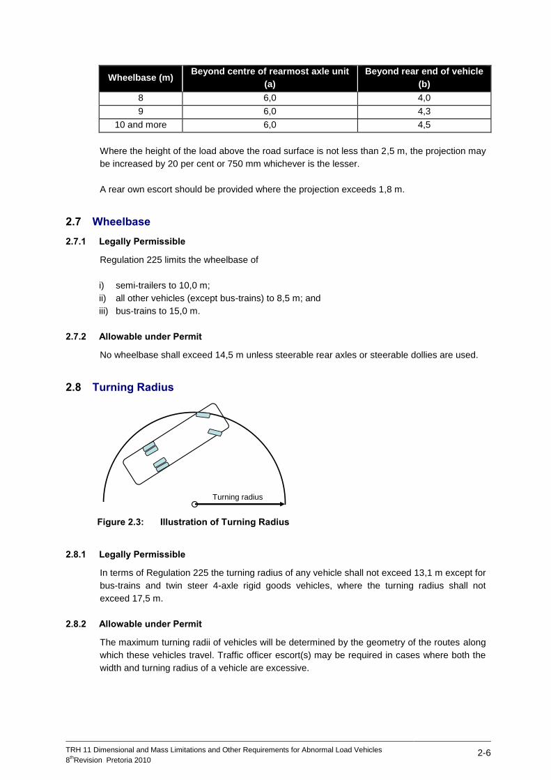
Table 2.6: Allowable Rear Load Projections
Wheelbase (m) Beyond centre of rearmost axle unit
(a)
Beyond rear end of vehicle
(b)
3 3,9 2,6
4 4,6 2,9
5 5,2 3,2
6 6,0 3,5
7 6,0 3,7
Load
projection
TRH 11 Dimensional and Mass Limitations and Other Requirements for Abnormal Load Vehicles
8thRevision Pretoria 2010
2-6
Wheelbase (m) Beyond centre of rearmost axle unit
(a)
Beyond rear end of vehicle
(b)
8 6,0 4,0
9 6,0 4,3
10 and more 6,0 4,5
Where the height of the load above the road surface is not less than 2,5 m, the projection may
be increased by 20 per cent or 750 mm whichever is the lesser.
A rear own escort should be provided where the projection exceeds 1,8 m.
2.7 Wheelbase
2.7.1 Legally Permissible
Regulation 225 limits the wheelbase of
i) semi-trailers to 10,0 m;
ii) all other vehicles (except bus-trains) to 8,5 m; and
iii) bus-trains to 15,0 m.
2.7.2 Allowable under Permit
No wheelbase shall exceed 14,5 m unless steerable rear axles or steerable dollies are used.
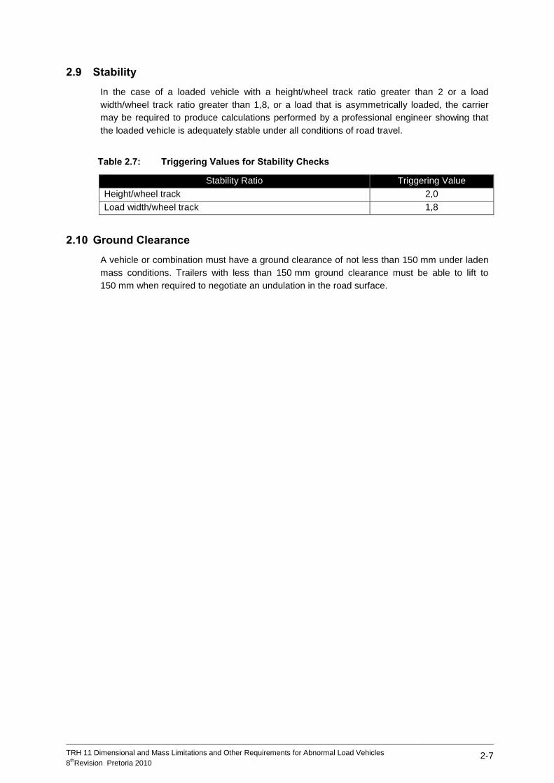
2.8 Turning Radius
Figure 2.3: Illustration of Turning Radius
2.8.1 Legally Permissible
In terms of Regulation 225 the turning radius of any vehicle shall not exceed 13,1 m except for
bus-trains and twin steer 4-axle rigid goods vehicles, where the turning radius shall not
exceed 17,5 m.
2.8.2 Allowable under Permit
The maximum turning radii of vehicles will be determined by the geometry of the routes along
which these vehicles travel. Traffic officer escort(s) may be required in cases where both the
width and turning radius of a vehicle are excessive.
Turning radius
TRH 11 Dimensional and Mass Limitations and Other Requirements for Abnormal Load Vehicles
8thRevision Pretoria 2010
2-7
2.9 Stability
In the case of a loaded vehicle with a height/wheel track ratio greater than 2 or a load
width/wheel track ratio greater than 1,8, or a load that is asymmetrically loaded, the carrier
may be required to produce calculations performed by a professional engineer showing that
the loaded vehicle is adequately stable under all conditions of road travel.
Table 2.7: Triggering Values for Stability Checks
Stability Ratio Triggering Value
Height/wheel track 2,0
Load width/wheel track 1,8
2.10 Ground Clearance
A vehicle or combination must have a ground clearance of not less than 150 mm under laden
mass conditions. Trailers with less than 150 mm ground clearance must be able to lift to
150 mm when required to negotiate an undulation in the road surface.
TRH 11 Dimensional and Mass Limitations and Other Requirements for Abnormal Load Vehicles
8thRevision Pretoria 2010
3-1
3 MASS LIMITATIONS
3.1 Background
The permissible maximum vehicle or combination mass of a road vehicle or combination of
road vehicles that is allowed to operate either legally or under permit on a public road is
limited by:
The capacity of the vehicles as rated by the manufacturer;
The load which may be carried by the tyres;
The damaging effect on road pavements;
The structural capacity of bridges and culverts;
The power of the prime mover(s);
The load imposed on the driving axles; and
The load imposed on the steering axles.
In this section the legal limits permitted by the NRTR are presented, as well as the
corresponding limits allowable under permit. In both cases, the lowest allowable mass
determines the permissible maximum masses which may be carried legally or under permit
respectively.
3.2 Loads on Tyres
Overloading of tyres may lead to tyre failure and may cause an accident endangering and
delaying other road users.
3.2.1 Legally Permissible
Regulation 238 stipulates that the limitations on the massload of wheels, as laid down in the
South African National Standard SANS 1550 and Recommended Practice ARP 007, shall
apply, or if SANS 1550 or ARP 007 do not contain the relevant tyre data, then the design
capacity as specified by the manufacturer must be adhered to.
3.2.2 Allowable under Permit
For vehicles operating under permit, the allowable loads given in SANS 1550 and ARP 007 or
by the manufacturer must not be exceeded. The speed restrictions must be rigidly adhered to
and the wheels and rims must be of adequate strength.
3.3 Manufacturer’s Ratings
Manufacturer’s rating refers to the maximum massload for an axle or axle unit or the
maximum mass of a vehicle or combination of vehicles as specified by the manufacturer. The
manufacturer’s ratings are referred to as “gross”, namely the gross vehicle mass (GVM),
gross combination mass (GCM), gross axle massload (GA) and gross axle unit massload
(GAU). This information must be clearly imprinted or stamped on the information plate, which
in terms of Regulation 245 of the NRTR is required to be affixed to, inter alia, goods vehicle
with a GVM exceeding 3 500 kg
TRH 11 Dimensional and Mass Limitations and Other Requirements for Abnormal Load Vehicles
8thRevision Pretoria 2010
3-2
3.3.1 Legally Permissible
Regulation 239 stipulates that the gross vehicle mass; gross combination mass; any gross
axle massload; or any gross axle unit massload, shall not be exceeded.
3.3.2 Allowable under Permit
No permit will be granted if any of the manufacturer’s ratings are exceeded.
3.4 Massload Carrying Capacity of Roads
Every wheel of a vehicle causes some structural damage (wear) to the road pavement. The
total damage to a road pavement caused by a vehicle is determined by the tyre pressure,
magnitude of the individual wheel loads and the spacing between the wheels. The closer the
spacing of the wheels the greater the resultant stresses in the road pavement. The concept of
the equivalent single wheel massload (ESWM) deals with this effect (see section 6.2).
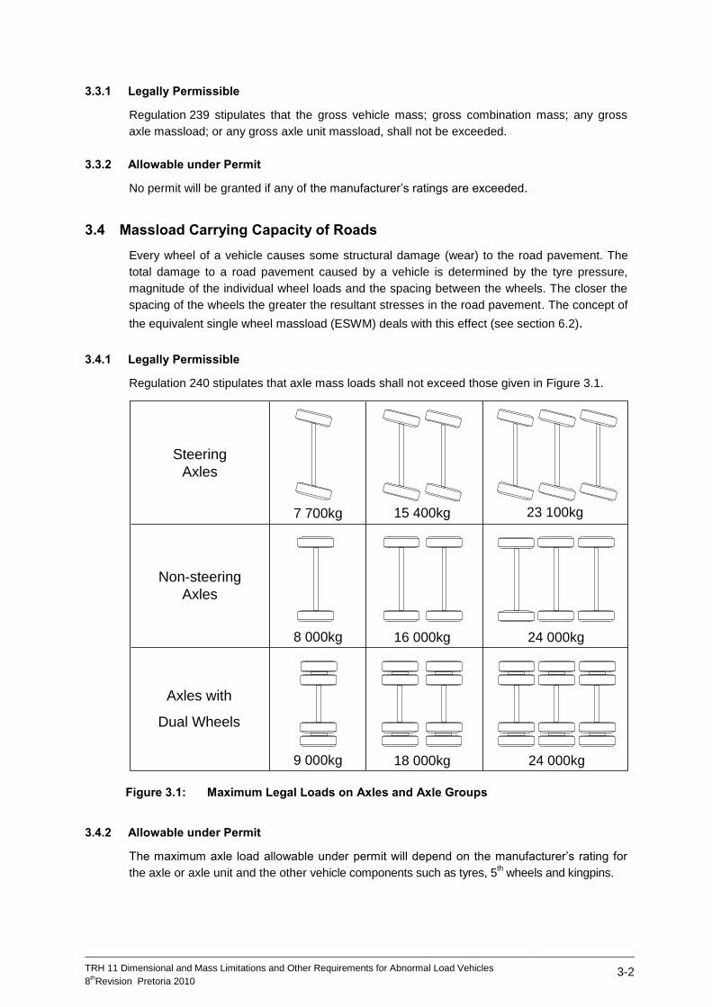
3.4.1 Legally Permissible
Regulation 240 stipulates that axle mass loads shall not exceed those given in Figure 3.1.
Figure 3.1: Maximum Legal Loads on Axles and Axle Groups
3.4.2 Allowable under Permit
The maximum axle load allowable under permit will depend on the manufacturer’s rating for
the axle or axle unit and the other vehicle components such as tyres, 5th wheels and kingpins.
Steering
Axles
Non-steering
Axles
Axles with
Dual Wheels
8 000kg
18 000kg
24 000kg
24 000kg
16 000kg
15 400kg
9 000kg
7 700kg 23 100kg
TRH 11 Dimensional and Mass Limitations and Other Requirements for Abnormal Load Vehicles
8thRevision Pretoria 2010
3-3
An ESWM of up to 6 500 kg may be allowed. Special consideration can be given to non-load
carrying vehicles:
All-terrain Mobile cranes may be allowed to exceed the ESWM limit of 6 500 kg per axle
provided that the axle loads of the all-terrain mobile crane is limited to 12 000 kg per axle;
Truck-mounted mobile cranes should at all times adhere to the terms and conditions of
TRH11 with a limit of 6 500 ESWM and should at all times comply with the bridge formula
in TRH11.
3.5 Massload Carrying Capacity of Bridges and Culverts
The load carrying capacity of bridges and culverts requires that the load intensity of a vehicle
be limited. The load carrying capacity of a bridge or culvert is determined by the design and
present condition of the structure. The load intensity of a vehicle is determined by the loads on
axles and axle units and the spacing of those axles and axle units. It is therefore necessary to
limit the load that is carried by a group of axles or axle units.
3.5.1 Legally Permissible
Regulation 241 states that the total axle massload of any group of axles on a vehicle or
combination of vehicles may not exceed the mass in kilogram calculated using the following
formula:
P = 18 000 + 2 100 x L
Where: P = Permissible Maximum Mass of the group of axles (in kg); and
L = Distance between the centre of the first axle of any group of axles to the
centre of the last axle of such group, measured in metres (rounded up to
the next highest tenth of a metre).
3.5.2 Allowable under Permit
In order to check whether an abnormal vehicle may be permitted to cross bridges and culverts
en route, it is necessary to calculate the maximum stresses that the abnormal vehicle with its
load will cause to be exerted on the various components of the bridges and culverts and then
to compare these with the maximum stresses for which the bridges and culverts were
designed.
Accurate calculations are complicated, laborious, time consuming and will normally not be
required for vehicles, or combinations of vehicles, other than all terrain mobile cranes, when
the laden mass of the vehicle and/or combination of vehicles does not exceed 125 000 kg,
provided the route is specified by the carrier.
3.5.2.1 All Terrain Mobile Cranes
A methodology was developed (reference 11) for assessing the impact of all terrain mobile
cranes on bridge and culvert structures. The approach uses a reference load (TMH7
NA+NB30 and compares the maximum bending moments and shear forces generated by a
mobile crane on a representative set of structures with those generated by the reference load.
These are expressed as load ratios of maximum bending moment and shear force. Both the
moment and shear ratio must be less than one for the all-terrain mobile crane to be granted an
exemption permit.
TRH 11 Dimensional and Mass Limitations and Other Requirements for Abnormal Load Vehicles
8thRevision Pretoria 2010
3-4
If either the shear force or bending moment ratio exceeds 0.85, i.e. 85% of the allowable
maximum load ratio of 1.0, RTMS certification in terms of SANS 1395 (2014) of the fleet of
which the specific mobile crane forms a part, is required. In addition, the road authority may,
at its discretion, impose further conditions, for example regarding under-strength structures on
specific routes.
3.5.2.2 Other Abnormal Vehicles
For other abnormal vehicles or combinations of vehicles with a total mass of less than
125 000 kg, any group of axles may not exceed the values given in Table 3.1. The limitations
imposed by bridges and culverts on multi axle groups are based on the following formula:
MAL = EW x (6,850 + 0,00145 x AD)
Where: MAL = Allowable maximum mass of the group of axles (in kg);
EW = Effective Width in mm; and
AD = Distance between the centre of the first axle of any group of axles
to the centre of the last axle of such group, measured in
millimetres.
In addition, unless specifically stated in the permit, no vehicle travelling under an abnormal
load permit shall cross any bridge if the total mass or any axle mass load exceeds the
maximum permitted for that bridge by an appropriate road traffic sign.
It is the responsibility of the carrier to ensure that the load can safely be carried by all bridges
and other structures at the time of the proposed journey. Proof will be required that a recent
investigation had been undertaken for the load or a similar or greater load.
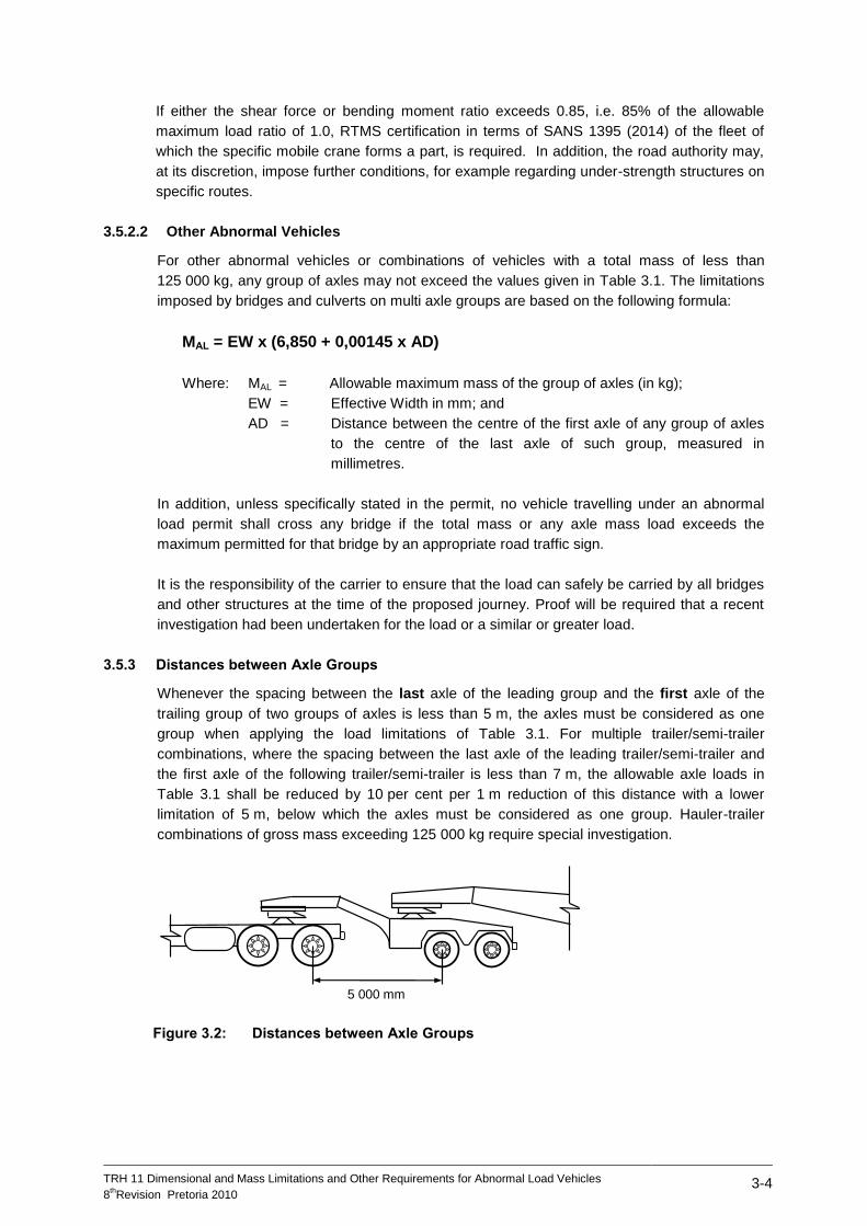
3.5.3 Distances between Axle Groups
Whenever the spacing between the last axle of the leading group and the first axle of the
trailing group of two groups of axles is less than 5 m, the axles must be considered as one
group when applying the load limitations of Table 3.1. For multiple trailer/semi-trailer
combinations, where the spacing between the last axle of the leading trailer/semi-trailer and
the first axle of the following trailer/semi-trailer is less than 7 m, the allowable axle loads in
Table 3.1 shall be reduced by 10 per cent per 1 m reduction of this distance with a lower
limitation of 5 m, below which the axles must be considered as one group. Hauler-trailer
combinations of gross mass exceeding 125 000 kg require special investigation.
Figure 3.2: Distances between Axle Groups
5 000 mm
TRH 11 Dimensional and Mass Limitations and Other Requirements for Abnormal Load Vehicles
8thRevision Pretoria 2010
3-5
3.5.4 Tracking Requirements
When determining the maximum allowable load, consideration must be given to other traffic
that may be present on a bridge. Moreover, very heavy load combinations should travel along
a path which minimises overstressing, usually the centreline of the bridge.
Vehicles or combinations of vehicles, in which the allowable axle group loading exceeds the
value in the extreme right hand column of the applicable line of Table 3.1, shall proceed so
that the centre of the load shall not be more than 1,0 m from the centre line of a bridge with an
overall length exceeding 60 m. In such cases, the structure will be temporarily closed to all
other road users. This condition must be clearly stated as a permit condition by the Issuing
Authority. It requires the services of at least two traffic officer escorts to control other traffic.
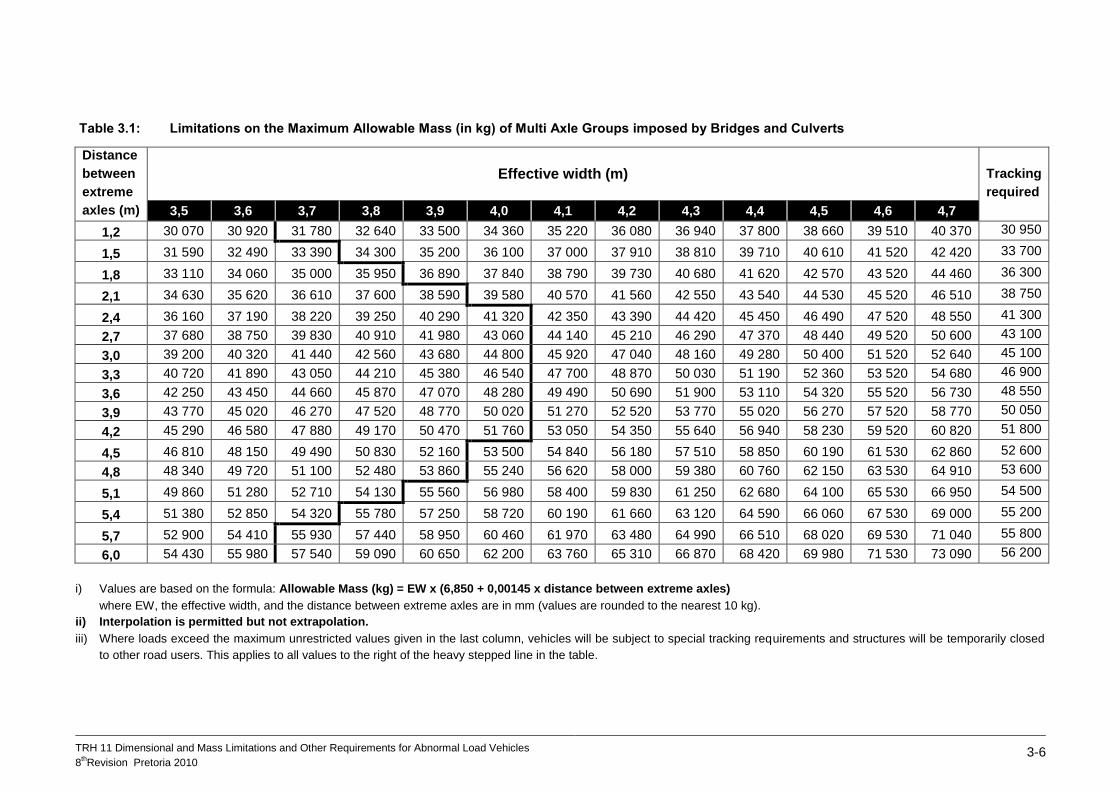
TRH 11 Dimensional and Mass Limitations and Other Requirements for Abnormal Load Vehicles
8thRevision Pretoria 2010
3-6
Table 3.1: Limitations on the Maximum Allowable Mass (in kg) of Multi Axle Groups imposed by Bridges and Culverts
Distance
between
extreme
axles (m)
Effective width (m) Tracking
required
3,5 3,6 3,7 3,8 3,9 4,0 4,1 4,2 4,3 4,4 4,5 4,6 4,7
1,2 30 070 30 920 31 780 32 640 33 500 34 360 35 220 36 080 36 940 37 800 38 660 39 510 40 370 30 950
1,5 31 590 32 490 33 390 34 300 35 200 36 100 37 000 37 910 38 810 39 710 40 610 41 520 42 420 33 700
1,8 33 110 34 060 35 000 35 950 36 890 37 840 38 790 39 730 40 680 41 620 42 570 43 520 44 460 36 300
2,1 34 630 35 620 36 610 37 600 38 590 39 580 40 570 41 560 42 550 43 540 44 530 45 520 46 510 38 750
2,4 36 160 37 190 38 220 39 250 40 290 41 320 42 350 43 390 44 420 45 450 46 490 47 520 48 550 41 300
2,7 37 680 38 750 39 830 40 910 41 980 43 060 44 140 45 210 46 290 47 370 48 440 49 520 50 600 43 100
3,0 39 200 40 320 41 440 42 560 43 680 44 800 45 920 47 040 48 160 49 280 50 400 51 520 52 640 45 100
3,3 40 720 41 890 43 050 44 210 45 380 46 540 47 700 48 870 50 030 51 190 52 360 53 520 54 680 46 900
3,6 42 250 43 450 44 660 45 870 47 070 48 280 49 490 50 690 51 900 53 110 54 320 55 520 56 730 48 550
3,9 43 770 45 020 46 270 47 520 48 770 50 020 51 270 52 520 53 770 55 020 56 270 57 520 58 770 50 050
4,2 45 290 46 580 47 880 49 170 50 470 51 760 53 050 54 350 55 640 56 940 58 230 59 520 60 820 51 800
4,5 46 810 48 150 49 490 50 830 52 160 53 500 54 840 56 180 57 510 58 850 60 190 61 530 62 860 52 600
4,8 48 340 49 720 51 100 52 480 53 860 55 240 56 620 58 000 59 380 60 760 62 150 63 530 64 910 53 600
5,1 49 860 51 280 52 710 54 130 55 560 56 980 58 400 59 830 61 250 62 680 64 100 65 530 66 950 54 500
5,4 51 380 52 850 54 320 55 780 57 250 58 720 60 190 61 660 63 120 64 590 66 060 67 530 69 000 55 200
5,7 52 900 54 410 55 930 57 440 58 950 60 460 61 970 63 480 64 990 66 510 68 020 69 530 71 040 55 800
6,0 54 430 55 980 57 540 59 090 60 650 62 200 63 760 65 310 66 870 68 420 69 980 71 530 73 090 56 200
i) Values are based on the formula: Allowable Mass (kg) = EW x (6,850 + 0,00145 x distance between extreme axles)
where EW, the effective width, and the distance between extreme axles are in mm (values are rounded to the nearest 10 kg).
ii) Interpolation is permitted but not extrapolation.
iii) Where loads exceed the maximum unrestricted values given in the last column, vehicles will be subject to special tracking requirements and structures will be temporarily closed
to other road users. This applies to all values to the right of the heavy stepped line in the table.
TRH 11 Dimensional and Mass Limitations and Other Requirements for Abnormal Load Vehicles
8thRevision Pretoria 2010
3-7
3.6 Limitations Imposed by Drawing Vehicles (Power to Mass Ratio)
It is important that legally loaded as well as abnormally loaded vehicles be adequately
powered so that a reasonable travel speed can be maintained to avoid unnecessary traffic
congestion.
3.6.1 Legally Permissible
Regulation 239 requires that the mass in kilograms of a vehicle or combination of vehicles
does not exceed a figure arrived at by multiplying the net power in kW of the engine of such
vehicle as determined in accordance with or calculated with due regard to Code of Practice
“SANS 10013-1 - The Determination of Performance (at net power) of Internal Combustion
Engines”:
i) in the case of the drawing vehicle being a tractor, by 400,
ii) in the case of any other vehicle, by 240.
3.6.2 Allowable under Permit
i) For abnormal vehicles and/or combination of vehicles with a total mass of less than
23 000 kg, the provisions of section 3.6.1 will apply.
ii) For abnormal vehicles and/or combination of vehicles with a total mass exceeding
23 000 kg, the net power in kW of the engine(s) of such vehicle, as determined in
accordance with or calculated with due regard to Code of Practice SANS 10013-1, shall
not be less than the value calculated using the following formula:
500
CM n) x (50 P
Where: P = Required net power in kW of the engine of the vehicle;
n = Number of drawing vehicles in the combination; and
CM = Total mass in kg of the combination of vehicles
except that in the case of mobile cranes and other similar specialised self-propelled
vehicles, the permissible maximum vehicle mass shall not exceed a figure arrived at by
multiplying the net power in kW of the engine of such vehicle as determined in accordance
with or calculated with due regard to Code of Practice SANS 10013-1, by 300.
iii) When two or more drawing vehicles are used to pull an abnormal load, each drawing
vehicle must have a GCM rating of at least 54 000 kg and an engine power of at least
220 kW and the drawing vehicles must be compatible in performance.
3.7 Massload on Drive Axles (Traction Ratio)
To ensure sufficient traction, a minimum ratio of massload on the drive axles to total vehicle/
combination mass is specified.
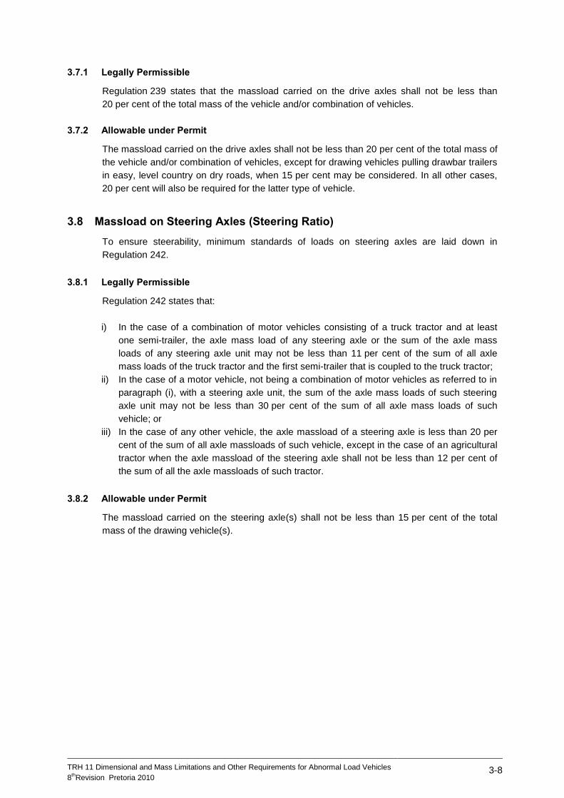
TRH 11 Dimensional and Mass Limitations and Other Requirements for Abnormal Load Vehicles
8thRevision Pretoria 2010
3-8
3.7.1 Legally Permissible
Regulation 239 states that the massload carried on the drive axles shall not be less than
20 per cent of the total mass of the vehicle and/or combination of vehicles.
3.7.2 Allowable under Permit
The massload carried on the drive axles shall not be less than 20 per cent of the total mass of
the vehicle and/or combination of vehicles, except for drawing vehicles pulling drawbar trailers
in easy, level country on dry roads, when 15 per cent may be considered. In all other cases,
20 per cent will also be required for the latter type of vehicle.
3.8 Massload on Steering Axles (Steering Ratio)
To ensure steerability, minimum standards of loads on steering axles are laid down in
Regulation 242.
3.8.1 Legally Permissible
Regulation 242 states that:
i) In the case of a combination of motor vehicles consisting of a truck tractor and at least
one semi-trailer, the axle mass load of any steering axle or the sum of the axle mass
loads of any steering axle unit may not be less than 11 per cent of the sum of all axle
mass loads of the truck tractor and the first semi-trailer that is coupled to the truck tractor;
ii) In the case of a motor vehicle, not being a combination of motor vehicles as referred to in
paragraph (i), with a steering axle unit, the sum of the axle mass loads of such steering
axle unit may not be less than 30 per cent of the sum of all axle mass loads of such
vehicle; or
iii) In the case of any other vehicle, the axle massload of a steering axle is less than 20 per
cent of the sum of all axle massloads of such vehicle, except in the case of an agricultural
tractor when the axle massload of the steering axle shall not be less than 12 per cent of
the sum of all the axle massloads of such tractor.
3.8.2 Allowable under Permit
The massload carried on the steering axle(s) shall not be less than 15 per cent of the total
mass of the drawing vehicle(s).
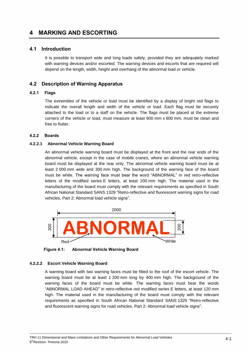
TRH 11 Dimensional and Mass Limitations and Other Requirements for Abnormal Load Vehicles
8thRevision Pretoria 2010
4-1
4 MARKING AND ESCORTING
4.1 Introduction
It is possible to transport wide and long loads safely, provided they are adequately marked
with warning devices and/or escorted. The warning devices and escorts that are required will
depend on the length, width, height and overhang of the abnormal load or vehicle.
4.2 Description of Warning Apparatus
4.2.1 Flags
The extremities of the vehicle or load must be identified by a display of bright red flags to
indicate the overall length and width of the vehicle or load. Each flag must be securely
attached to the load or to a staff on the vehicle. The flags must be placed at the extreme
corners of the vehicle or load, must measure at least 600 mm x 600 mm, must be clean and
free to flutter.
4.2.2 Boards
4.2.2.1 Abnormal Vehicle Warning Board
An abnormal vehicle warning board must be displayed at the front and the rear ends of the
abnormal vehicle, except in the case of mobile cranes, where an abnormal vehicle warning
board must be displayed at the rear only. The abnormal vehicle warning board must be at
least 2 000 mm wide and 300 mm high. The background of the warning face of the board
must be white. The warning face must bear the word “ABNORMAL” in red retro-reflective
letters of the modified series E letters, at least 200 mm high. The material used in the
manufacturing of the board must comply with the relevant requirements as specified in South
African National Standard SANS 1329 "Retro-reflective and fluorescent warning signs for road
vehicles, Part 2: Abnormal load vehicle signs”.
Figure 4.1: Abnormal Vehicle Warning Board
4.2.2.2 Escort Vehicle Warning Board
A warning board with two warning faces must be fitted to the roof of the escort vehicle. The
warning board must be at least 1 200 mm long by 400 mm high. The background of the
warning faces of the board must be white. The warning faces must bear the words
“ABNORMAL LOAD AHEAD” in retro-reflective red modified series E letters, at least 120 mm
high. The material used in the manufacturing of the board must comply with the relevant
requirements as specified in South African National Standard SANS 1329 "Retro-reflective
and fluorescent warning signs for road vehicles, Part 2: Abnormal load vehicle signs”.
ABNORMALRed White
300
2000
200
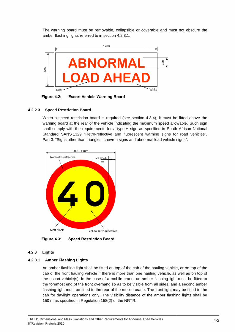
TRH 11 Dimensional and Mass Limitations and Other Requirements for Abnormal Load Vehicles
8thRevision Pretoria 2010
4-2
The warning board must be removable, collapsible or coverable and must not obscure the
amber flashing lights referred to in section 4.2.3.1.
Figure 4.2: Escort Vehicle Warning Board
4.2.2.3 Speed Restriction Board
When a speed restriction board is required (see section 4.3.4), it must be fitted above the
warning board at the rear of the vehicle indicating the maximum speed allowable. Such sign
shall comply with the requirements for a type H sign as specified in South African National
Standard SANS 1329 "Retro-reflective and fluorescent warning signs for road vehicles",
Part 3: "Signs other than triangles, chevron signs and abnormal load vehicle signs".
Figure 4.3: Speed Restriction Board
4.2.3 Lights
4.2.3.1 Amber Flashing Lights
An amber flashing light shall be fitted on top of the cab of the hauling vehicle, or on top of the
cab of the front hauling vehicle if there is more than one hauling vehicle, as well as on top of
the escort vehicle(s). In the case of a mobile crane, an amber flashing light must be fitted to
the foremost end of the front overhang so as to be visible from all sides, and a second amber
flashing light must be fitted to the rear of the mobile crane. The front light may be fitted to the
cab for daylight operations only. The visibility distance of the amber flashing lights shall be
150 m as specified in Regulation 158(2) of the NRTR.
Red White
400
1200
120ABNORMAL
LOAD AHEAD
Red retro-reflective
Yellow retro-reflective
200 ± 1 mm
25 ± 0.5
mm
Matt black
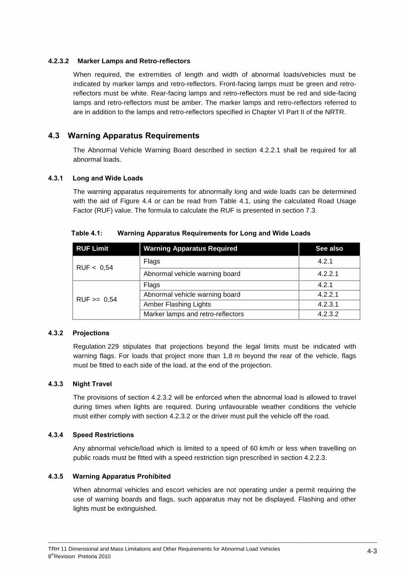
TRH 11 Dimensional and Mass Limitations and Other Requirements for Abnormal Load Vehicles
8thRevision Pretoria 2010
4-3
4.2.3.2 Marker Lamps and Retro-reflectors
When required, the extremities of length and width of abnormal loads/vehicles must be
indicated by marker lamps and retro-reflectors. Front-facing lamps must be green and retro-
reflectors must be white. Rear-facing lamps and retro-reflectors must be red and side-facing
lamps and retro-reflectors must be amber. The marker lamps and retro-reflectors referred to
are in addition to the lamps and retro-reflectors specified in Chapter VI Part II of the NRTR.
4.3 Warning Apparatus Requirements
The Abnormal Vehicle Warning Board described in section 4.2.2.1 shall be required for all
abnormal loads.
4.3.1 Long and Wide Loads
The warning apparatus requirements for abnormally long and wide loads can be determined
with the aid of Figure 4.4 or can be read from Table 4.1, using the calculated Road Usage
Factor (RUF) value. The formula to calculate the RUF is presented in section 7.3.
Table 4.1: Warning Apparatus Requirements for Long and Wide Loads
RUF Limit Warning Apparatus Required See also
RUF < 0,54 Flags 4.2.1
Abnormal vehicle warning board 4.2.2.1
RUF >= 0,54
Flags 4.2.1
Abnormal vehicle warning board 4.2.2.1
Amber Flashing Lights 4.2.3.1
Marker lamps and retro-reflectors 4.2.3.2
4.3.2 Projections
Regulation 229 stipulates that projections beyond the legal limits must be indicated with
warning flags. For loads that project more than 1,8 m beyond the rear of the vehicle, flags
must be fitted to each side of the load, at the end of the projection.
4.3.3 Night Travel
The provisions of section 4.2.3.2 will be enforced when the abnormal load is allowed to travel
during times when lights are required. During unfavourable weather conditions the vehicle
must either comply with section 4.2.3.2 or the driver must pull the vehicle off the road.
4.3.4 Speed Restrictions
Any abnormal vehicle/load which is limited to a speed of 60 km/h or less when travelling on
public roads must be fitted with a speed restriction sign prescribed in section 4.2.2.3.
4.3.5 Warning Apparatus Prohibited
When abnormal vehicles and escort vehicles are not operating under a permit requiring the
use of warning boards and flags, such apparatus may not be displayed. Flashing and other
lights must be extinguished.
TRH 11 Dimensional and Mass Limitations and Other Requirements for Abnormal Load Vehicles
8thRevision Pretoria 2010
4-4
4.4 Escorting of Abnormal Vehicles
4.4.1 Background
An abnormal vehicle is accompanied by escort vehicles to warn the normal travelling public of
the abnormal vehicle and to promote a safer flow of traffic in the face of possible disruption
caused by the abnormal vehicle.
Unless specifically authorised, a private escort has no legal authority to control other traffic.
However, when it is necessary for a private escort to control other traffic, it shall always be
done in a reasonable manner, bearing in mind that the safety and convenience of other road
users shall always enjoy precedence over that of the abnormal vehicle.
4.4.2 Escort Classes
4.4.2.1 Own Escort
An own escort is an escort vehicle that is provided by the carrier, which should be a
passenger motor car or a light motor vehicle as defined in the NRTA with a GVM not
exceeding 3 500 kg. The escort vehicle must be equipped with an amber flashing light and an
abnormal vehicle warning board on the roof of the vehicle, positioned such that it is visible
from all directions.
Where a single own escort vehicle is specified, the escort vehicle must travel between 10 m
and 50 m behind the abnormal vehicle, as far back as possible within sight of it, to give other
road users timely warning of the presence of the abnormal vehicle, but allowing normal
overtaking when conditions allow. When the abnormality is caused by an excessive front
overhang or when a height gauge is prescribed for loads exceeding 4,7 m, the escorting
vehicle must travel in front of the abnormal vehicle.
Where two own escort vehicles are specified, the one vehicle must travel in front and the
other vehicle behind the abnormal vehicle, travelling between 10 m and 50 m from the
abnormal vehicle.
4.4.2.2 Traffic Officer Escort
Traffic officer escorts are provided by the road traffic authorities and will normally consist of
two vehicles. In some cases, one traffic officer escort vehicle may be replaced by an own
escort vehicle at the discretion of the permit office.
4.4.3 Escort Requirements
4.4.3.1 Width and Length
The class and number of escorts required are a function of both the length and the width of
the loaded vehicle. The requirements for escorts, in terms of the dimension class (see Table
1.1) and route category (see Table 1.3), are presented in Table 4.2.
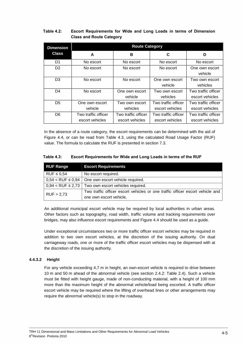
TRH 11 Dimensional and Mass Limitations and Other Requirements for Abnormal Load Vehicles
8thRevision Pretoria 2010
4-5
Table 4.2: Escort Requirements for Wide and Long Loads in terms of Dimension
Class and Route Category
Dimension
Class
Route Category
A B C D
D1 No escort No escort No escort No escort
D2 No escort No escort No escort One own escort
vehicle
D3 No escort No escort One own escort
vehicle
Two own escort
vehicles
D4 No escort One own escort
vehicle
Two own escort
vehicles
Two traffic officer
escort vehicles
D5 One own escort
vehicle
Two own escort
vehicles
Two traffic officer
escort vehicles
Two traffic officer
escort vehicles
D6 Two traffic officer
escort vehicles
Two traffic officer
escort vehicles
Two traffic officer
escort vehicles
Two traffic officer
escort vehicles
In the absence of a route category, the escort requirements can be determined with the aid of
Figure 4.4, or can be read from Table 4.3, using the calculated Road Usage Factor (RUF)
value. The formula to calculate the RUF is presented in section 7.3.
Table 4.3: Escort Requirements for Wide and Long Loads in terms of the RUF
RUF Range Escort Requirements
RUF ≤ 0,54 No escort required.
0,54 < RUF ≤ 0,94 One own escort vehicle required.
0,94 < RUF ≤ 2,73 Two own escort vehicles required.
RUF > 2,73 Two traffic officer escort vehicles or one traffic officer escort vehicle and
one own escort vehicle.
An additional municipal escort vehicle may be required by local authorities in urban areas.
Other factors such as topography, road width, traffic volume and tracking requirements over
bridges, may also influence escort requirements and Figure 4.4 should be used as a guide.
Under exceptional circumstances two or more traffic officer escort vehicles may be required in
addition to two own escort vehicles, at the discretion of the issuing authority. On dual
carriageway roads, one or more of the traffic officer escort vehicles may be dispensed with at
the discretion of the issuing authority.
4.4.3.2 Height
For any vehicle exceeding 4,7 m in height, an own-escort vehicle is required to drive between
10 m and 50 m ahead of the abnormal vehicle (see section 2.4.2: Table 2.4). Such a vehicle
must be fitted with height gauge, made of non-conducting material, with a height of 100 mm
more than the maximum height of the abnormal vehicle/load being escorted. A traffic officer
escort vehicle may be required where the lifting of overhead lines or other arrangements may
require the abnormal vehicle(s) to stop in the roadway.
TRH 11 Dimensional and Mass Limitations and Other Requirements for Abnormal Load Vehicles
8thRevision Pretoria 2010
4-6
4.4.3.3 Overhangs
Where the front overhang of a mobile crane or foundation digger exceeds either of the
following, one own escort vehicle must be provided:
Overhang exceeds 4,5 m measured from the front surface of the backrest of the driver's
seat; or
Overhang exceeds 6,5 m measured from the centre of the front axle.
Where the front overhang exceeds 8 m, a traffic officer escort vehicle may, at the discretion of
the Issuing Authority, be required in addition to the own escort.
4.4.3.4 Load Projections
Where the rear load projection exceeds 1,8 m, one own escort vehicle must be provided to
travel behind the load.
4.4.3.5 Mass
When tracking over bridges is required in terms of Table 3.1, at least one traffic officer escort
vehicle is required.
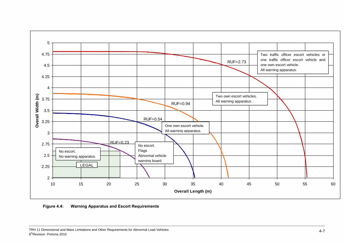
TRH 11 Dimensional and Mass Limitations and Other Requirements for Abnormal Load Vehicles
8thRevision Pretoria 2010
4-7
Figure 4.4: Warning Apparatus and Escort Requirements
2
2.25
2.5
2.75
3
3.25
3.5
3.75
4
4.25
4.5
4.75
5
10 15 20 25 30 35 40 45 50 55 60
Overall Length (m)
Overa
ll W
idth
(m
)
LEGAL
RUF=0.23
RUF=0.54
RUF=0.94
RUF=2.73
Two traffic officer escort vehicles or
one traffic officer escort vehicle and
one own escort vehicle.
All warning apparatus.
Two own escort vehicles.
All warning apparatus.
One own escort vehicle.
All warning apparatus.
No escort.
Flags
Abnormal vehicle
warning board
No escort.
No warning apparatus.

TRH 11 Dimensional and Mass Limitations and Other Requirements for Abnormal Load Vehicles
8thRevision Pretoria 2010
5-1
5 SPEED RESTRICTIONS
5.1 Background
The maximum speed at which an abnormal vehicle is permitted to travel on public roads is
dependent on factors such as the load on the tyres, the load on bridges and the dimensions of
the loaded vehicle.
5.2 Tyre Loading
It may become necessary to restrict the speed of an abnormally heavy vehicle to enable
heavier loads to be carried safely on tyres. These restricted speeds are given in Table 5.1.
Table 5.1: Speed Restrictions due to Tyre Loading
Ratio a – b
a – c Maximum speed (km/h)
0,00 – 0,07 30
0,08 – 0,21 40
0,22 - 0,36 50
0,37 - 0,50 60
0,51 - 0,64 70
0,65 - 1,00 80
Where: a = maximum combination mass allowable under permit b = actual combination mass for which permit is issued c = legal permissible maximum combination mass
Table 5.1 is based on the ETRTO Standards Manual, a normative reference in SANS 1550-1:
Part 1 Motor vehicle tyres and rims — Dimensions and loads, which allow tyre loading
capacity to be increased if the vehicle speed is limited to 30 km/h. For legally loaded vehicles
no special speed restrictions are required and for intermediate loads intermediate speeds on a
proportional basis may be permitted.
5.3 Bridge Loading
For abnormally heavy vehicles, lower speeds are required over bridges in order to reduce the
magnitude of the impact forces. These maximum speeds are given in Table 5.2.
Table 5.2: Maximum Allowable Speeds over Bridges
Total combination mass
(kg)
Maximum allowable speed over bridge
(km/h)
Not exceeding 50 000 80
60 000 70
70 000 60
80 000 50
90 000 40
100 000 30
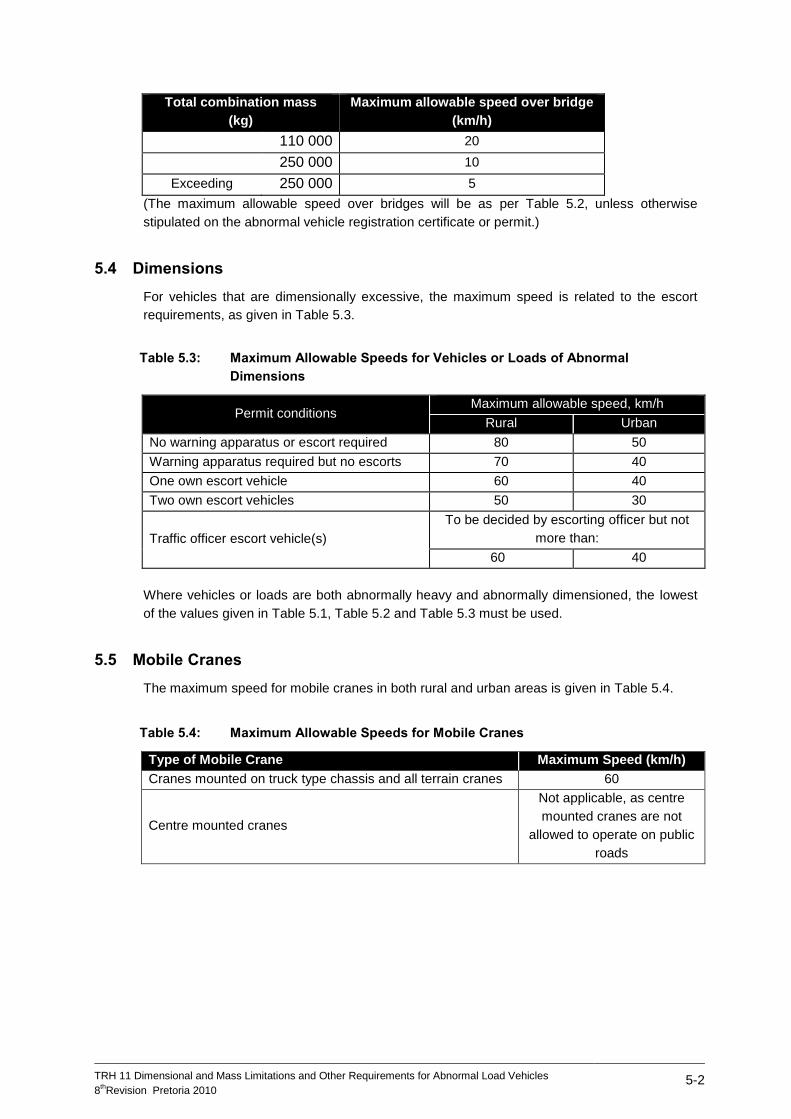
TRH 11 Dimensional and Mass Limitations and Other Requirements for Abnormal Load Vehicles
8thRevision Pretoria 2010
5-2
Total combination mass
(kg)
Maximum allowable speed over bridge
(km/h)
110 000 20
250 000 10
Exceeding 250 000 5
(The maximum allowable speed over bridges will be as per Table 5.2, unless otherwise
stipulated on the abnormal vehicle registration certificate or permit.)
5.4 Dimensions
For vehicles that are dimensionally excessive, the maximum speed is related to the escort
requirements, as given in Table 5.3.
Table 5.3: Maximum Allowable Speeds for Vehicles or Loads of Abnormal
Dimensions
Permit conditions Maximum allowable speed, km/h
Rural Urban
No warning apparatus or escort required 80 50
Warning apparatus required but no escorts 70 40
One own escort vehicle 60 40
Two own escort vehicles 50 30
Traffic officer escort vehicle(s)
To be decided by escorting officer but not
more than:
60 40
Where vehicles or loads are both abnormally heavy and abnormally dimensioned, the lowest
of the values given in Table 5.1, Table 5.2 and Table 5.3 must be used.
5.5 Mobile Cranes
The maximum speed for mobile cranes in both rural and urban areas is given in Table 5.4.
Table 5.4: Maximum Allowable Speeds for Mobile Cranes
Type of Mobile Crane Maximum Speed (km/h)
Cranes mounted on truck type chassis and all terrain cranes 60
Centre mounted cranes
Not applicable, as centre
mounted cranes are not
allowed to operate on public
roads
TRH 11 Dimensional and Mass Limitations and Other Requirements for Abnormal Load Vehicles
8thRevision Pretoria 2010
6-1
6 ESTIMATION OF RELATIVE ROAD PAVEMENT DAMAGE BY
ABNORMAL VEHICLES
6.1 Introduction
One of the fundamental principles guiding the process of issuing exemption permits for the
transport of abnormal loads is that the damage to the road infrastructure by an abnormal
vehicle has to be recovered from the carrier.
To recover the damage done to road pavements by abnormal vehicles, a mass fee in R/km is
calculated and then multiplied by the distance to be travelled by the abnormal vehicle to
determine an amount payable.
To determine a mass fee, three steps are required in general:
Step 1: Convert the various arrangements of wheels and axles into a measure that
allows a rational comparison of these arrangements;
Step 2: Determine the relative damage caused by a particular arrangement of
wheels and axles as compared to some standard; and
Step 3: Determine the cost of such damage
Various methods can be used to convert the various arrangements of wheels and axles into a
measure that allows a rational comparison of these arrangements and to determine the
relative damage caused by a particular arrangement of wheels and axles as compared to
some standard.
One method is based on the well-known Equivalent Standard Axle concept, which is
described in TRH 16: 1991 Traffic Loading for Pavement and Rehabilitation Design. Two
other methods are the Equivalent Single Wheel Mass (ESWM) method and a method based
on the South African mechanistic-empirical pavement design methodology (SAMDM).
6.2 Equivalent Single Wheel Mass (ESWM) Method
The ESWM of a group of wheel loads is that load on a single standard wheel load that
induces the same critical stress and/or deflections in the road pavement as that induced by
the group of wheel loads. The basis for this calculation in South Africa was established by Van
Vuuren in 1972 (Reference 7). This principle was reviewed in 1994 and implemented in the
Sixth Revision of TRH 11 (September 1997). The review incorporated some of the
mechanistic-empirical (M-E) approaches for road pavement design. A description of this
method and the formulas used can be found in Reference 8 and Reference 9.
6.3 South African Mechanistic-empirical Pavement Design Methodology
(SAMDM)
This approach involves the use of the SAMDM methodology to estimate the Load Equivalency
Factors (LEFs) of each vehicle under static loading, based on the critical pavement layer life
approach. The philosophy of “Equivalent Pavement Response - Equivalent Pavement
Damage” (EPR-EPD) is used instead of reducing an abnormal vehicle to a single ESWM, or
to an equivalent Standard Axle Load (Reference 10).
TRH 11 Dimensional and Mass Limitations and Other Requirements for Abnormal Load Vehicles
8thRevision Pretoria 2010
6-2
With the EPR-EPD approach, no “fixed equivalencies” are used per se, and each vehicle is
considered with its full axle/tyre configuration (i.e. tyre/axle loading and its associated tyre
inflation pressure) as input into the SAMDM and the road damage (or “additional pavement
damage”) of the abnormal vehicle is directly estimated for the pavement type under
consideration. With the EPR-EPD approach the stresses and strains (i.e. mechanistic
pavement response parameters) are directly related through the associated transfer functions
(TF) for pavement damage to layer life and hence “pavement life”. With this approach, the
pavement life is considered as being equal to the “critical layer life”, i.e. the life of the
structural layer with the lowest life in the pavement structure.
The “pavement life” under each axle of the vehicle is calculated, summed and compared
relative to the bearing capacity of the pavement in terms of the Standard 80 kN/520 kPa axle
with four tyres (two dual sets) at a tyre inflation pressure of 520 kPa.
The Total Damage of the vehicle (TDv) is calculated as the sum of the ratios (for all axles of a
particular vehicle) between the critical layer life of the pavement determined from the
Standard 80 kN/520 kPa axle with four tyres (two dual sets) at an inflation pressure of
520 kPa (i.e. the bearing capacity of the pavement), divided by the critical layer life under
each individual axle load and its associated tyre pressures. This TDv is taken as the LEF.
The Mass Fee/km in ZAR is then equal to TDv x R, where R = the average cost estimate of
one “Standard Axle-lane-km” of road in SA in ZAR.
The pavement life is calculated using the mePADS software of the SAMDM. The basic
mechanistic-empirical methodology is freely available within South Africa from the CSIR Built
Environment (mePADS, 2008) - see website: http://asphalt.csir.co.za/samdm/.
More information is available in Reference 10.

TRH 11 Dimensional and Mass Limitations and Other Requirements for Abnormal Load Vehicles
8thRevision Pretoria 2010
7-1
7 TECHNICAL DETAIL AND CALCULATIONS
7.1 Introduction
This section contains reference material to some of the technical details and calculations used
in the document.
7.2 Detailed Glossary
7.2.1 5th
Wheel
A device fitted to a truck-tractor, adapter or converter dolly in order to permit articulation
between the said unit and a semi-trailer.
Figure 7.1: 5th
Wheel on Truck Tractor
7.2.2 Axle Configurations
Figure 7.2: Common Axle Configurations on Abnormal Vehicles
Single 4 Single in line
Dual 4 Dual in line
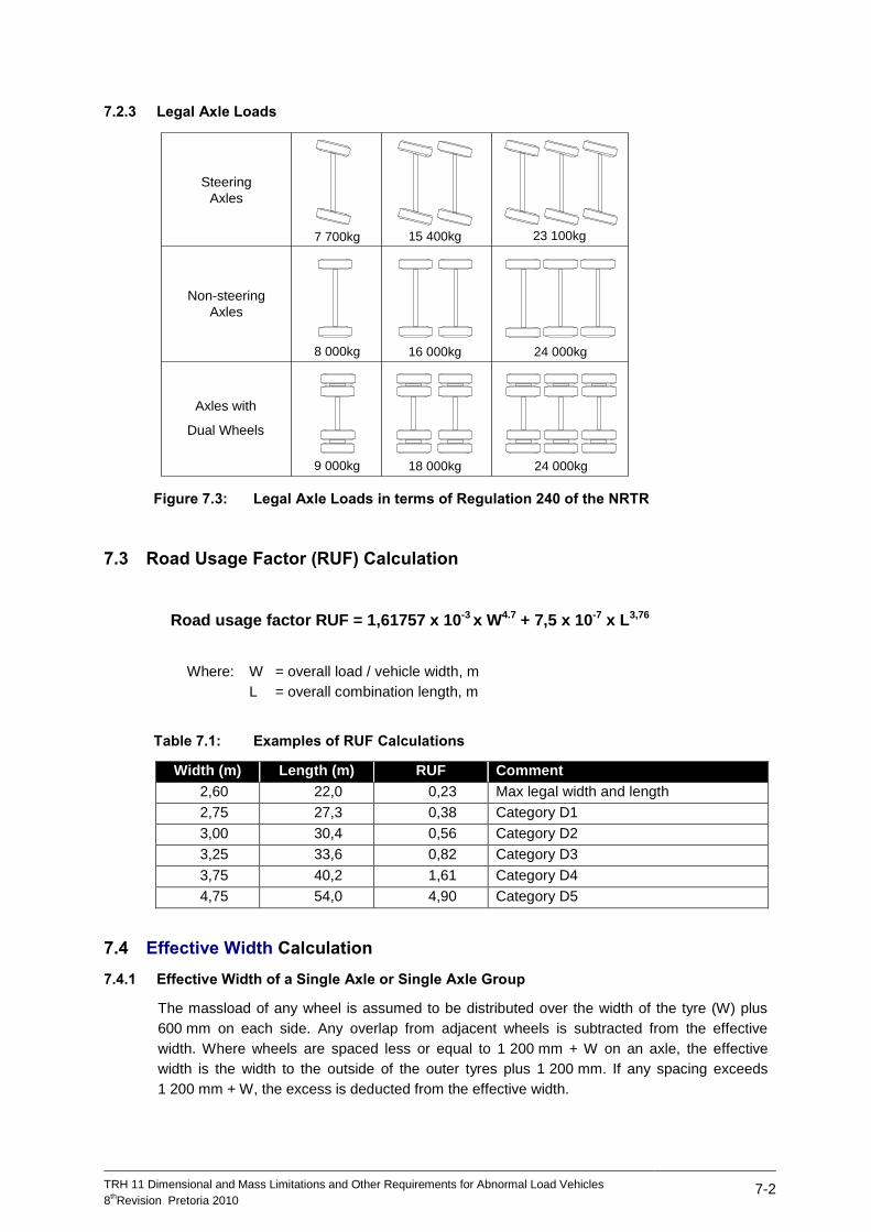
TRH 11 Dimensional and Mass Limitations and Other Requirements for Abnormal Load Vehicles
8thRevision Pretoria 2010
7-2
7.2.3 Legal Axle Loads
Figure 7.3: Legal Axle Loads in terms of Regulation 240 of the NRTR
7.3 Road Usage Factor (RUF) Calculation
Road usage factor RUF = 1,61757 x 10⁻³ x W4.7 + 7,5 x 10⁻⁷ x L3,76
Where: W = overall load / vehicle width, m
L = overall combination length, m
Table 7.1: Examples of RUF Calculations
Width (m) Length (m) RUF Comment
2,60 22,0 0,23 Max legal width and length
2,75 27,3 0,38 Category D1
3,00 30,4 0,56 Category D2
3,25 33,6 0,82 Category D3
3,75 40,2 1,61 Category D4
4,75 54,0 4,90 Category D5
7.4 Effective Width Calculation
7.4.1 Effective Width of a Single Axle or Single Axle Group
The massload of any wheel is assumed to be distributed over the width of the tyre (W) plus
600 mm on each side. Any overlap from adjacent wheels is subtracted from the effective
width. Where wheels are spaced less or equal to 1 200 mm + W on an axle, the effective
width is the width to the outside of the outer tyres plus 1 200 mm. If any spacing exceeds
1 200 mm + W, the excess is deducted from the effective width.
Steering
Axles
Non-steering
Axles
Axles with
Dual Wheels
8 000kg
18 000kg
24 000kg
24 000kg
16 000kg
15 400kg
9 000kg
7 700kg 23 100kg
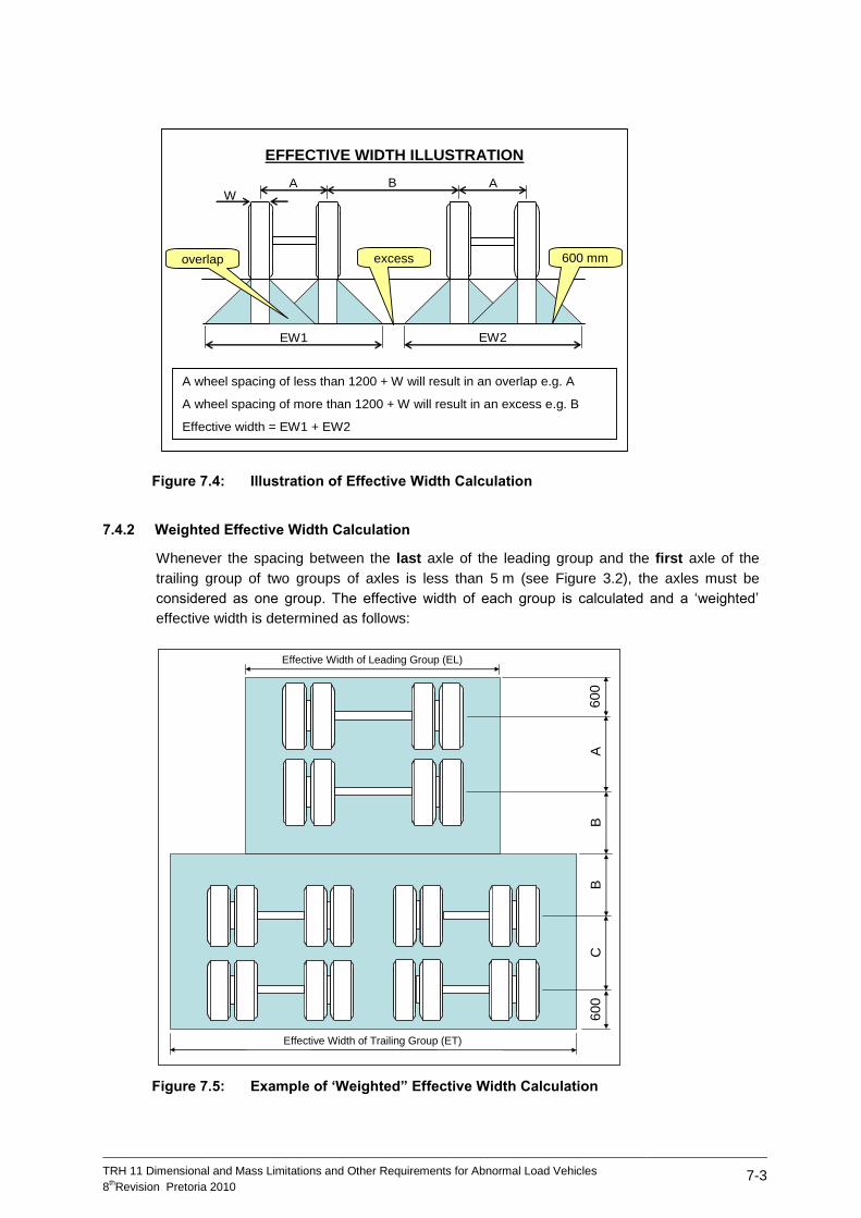
TRH 11 Dimensional and Mass Limitations and Other Requirements for Abnormal Load Vehicles
8thRevision Pretoria 2010
7-3
Figure 7.4: Illustration of Effective Width Calculation
7.4.2 Weighted Effective Width Calculation
Whenever the spacing between the last axle of the leading group and the first axle of the
trailing group of two groups of axles is less than 5 m (see Figure 3.2), the axles must be
considered as one group. The effective width of each group is calculated and a ‘weighted’
effective width is determined as follows:
Figure 7.5: Example of ‘Weighted” Effective Width Calculation
EW1
BA A
EFFECTIVE WIDTH ILLUSTRATION
EW2
W
excessoverlap
A wheel spacing of less than 1200 + W will result in an overlap e.g. A
A wheel spacing of more than 1200 + W will result in an excess e.g. B
Effective width = EW1 + EW2
600 mm
Effective Width of Trailing Group (ET)
Effective Width of Leading Group (EL)
600
600
BB
AC
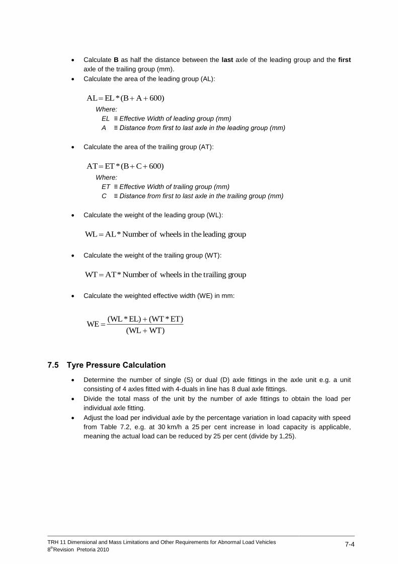
TRH 11 Dimensional and Mass Limitations and Other Requirements for Abnormal Load Vehicles
8thRevision Pretoria 2010
7-4
Calculate B as half the distance between the last axle of the leading group and the first
axle of the trailing group (mm).
Calculate the area of the leading group (AL):
600) A (B * EL AL
Where:
EL ≡ Effective Width of leading group (mm)
A ≡ Distance from first to last axle in the leading group (mm)
Calculate the area of the trailing group (AT):
600) C (B * ET AT
Where:
ET ≡ Effective Width of trailing group (mm)
C ≡ Distance from first to last axle in the trailing group (mm)
Calculate the weight of the leading group (WL):
group leading in the wheelsofNumber * AL WL
Calculate the weight of the trailing group (WT):
group trailingin the wheelsofNumber * AT WT
Calculate the weighted effective width (WE) in mm:
WT) (WL
ET) * (WT EL) * (WL WE
7.5 Tyre Pressure Calculation
Determine the number of single (S) or dual (D) axle fittings in the axle unit e.g. a unit
consisting of 4 axles fitted with 4-duals in line has 8 dual axle fittings.
Divide the total mass of the unit by the number of axle fittings to obtain the load per
individual axle fitting.
Adjust the load per individual axle by the percentage variation in load capacity with speed
from Table 7.2, e.g. at 30 km/h a 25 per cent increase in load capacity is applicable,
meaning the actual load can be reduced by 25 per cent (divide by 1,25).
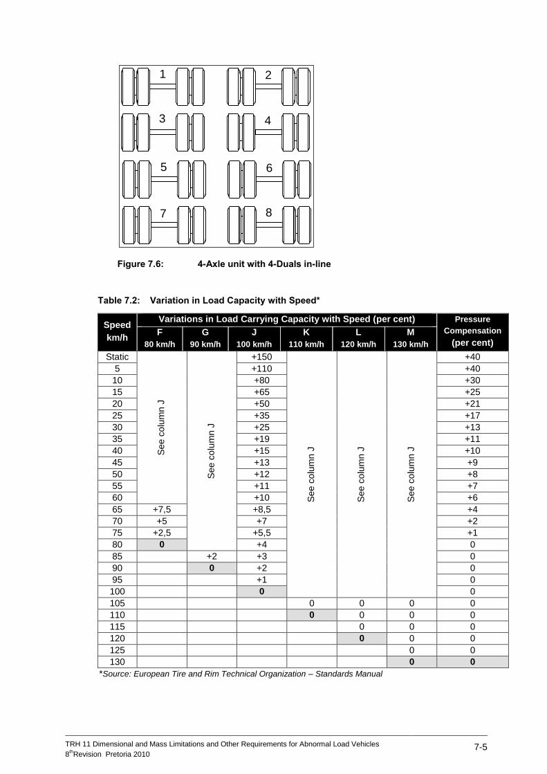
TRH 11 Dimensional and Mass Limitations and Other Requirements for Abnormal Load Vehicles
8thRevision Pretoria 2010
7-5
Figure 7.6: 4-Axle unit with 4-Duals in-line
Table 7.2: Variation in Load Capacity with Speed*
Speed
km/h
Variations in Load Carrying Capacity with Speed (per cent) Pressure
Compensation
(per cent) F
80 km/h
G
90 km/h
J
100 km/h
K
110 km/h
L
120 km/h
M
130 km/h
Static
See c
olu
mn J
See c
olu
mn J
+150
See c
olu
mn J
See c
olu
mn J
See c
olu
mn J
+40
5 +110 +40
10 +80 +30
15 +65 +25
20 +50 +21
25 +35 +17
30 +25 +13
35 +19 +11
40 +15 +10
45 +13 +9
50 +12 +8
55 +11 +7
60 +10 +6
65 +7,5 +8,5 +4
70 +5 +7 +2
75 +2,5 +5,5 +1
80 0 +4 0
85 +2 +3 0
90 0 +2 0
95 +1 0
100 0 0
105 0 0 0 0
110 0 0 0 0
115 0 0 0
120 0 0 0
125 0 0
130 0 0
*Source: European Tire and Rim Technical Organization – Standards Manual
1 2
3 4
5 6
7 8
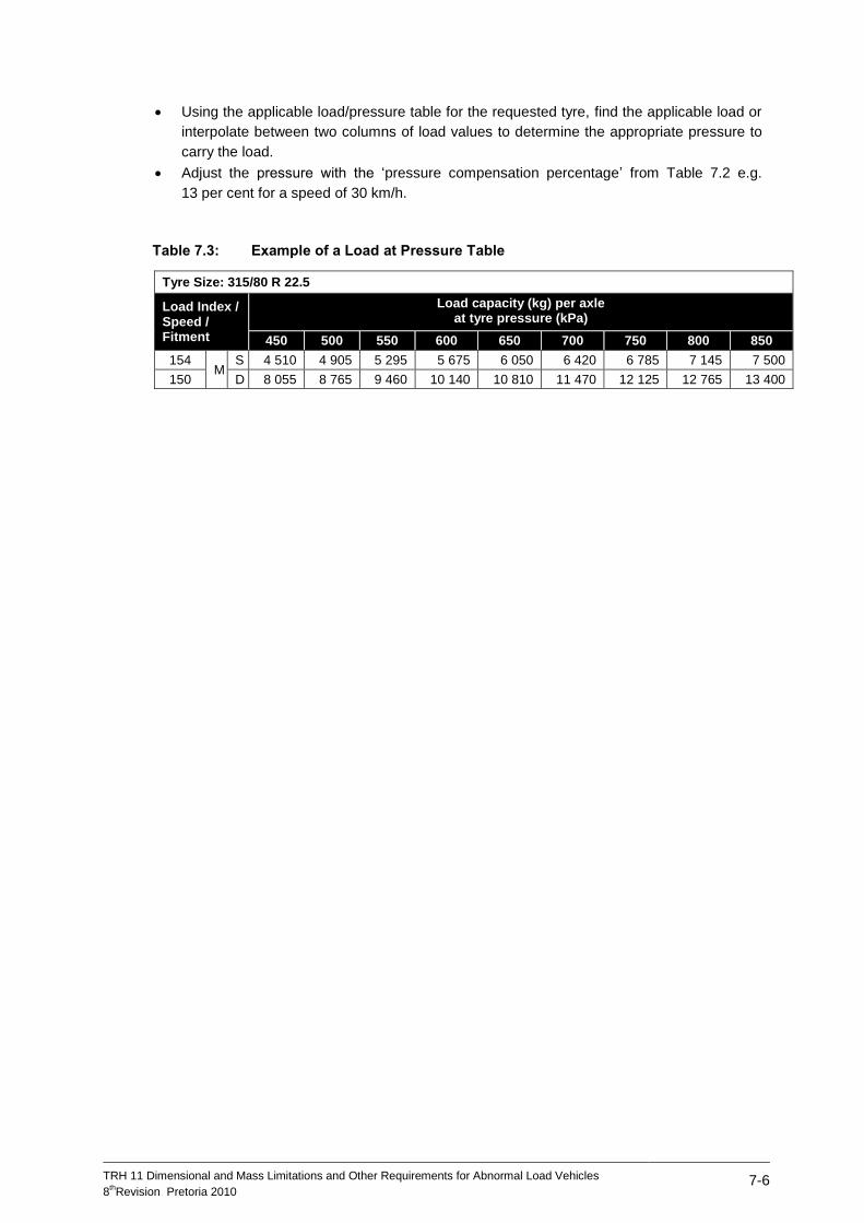
TRH 11 Dimensional and Mass Limitations and Other Requirements for Abnormal Load Vehicles
8thRevision Pretoria 2010
7-6
Using the applicable load/pressure table for the requested tyre, find the applicable load or
interpolate between two columns of load values to determine the appropriate pressure to
carry the load.
Adjust the pressure with the ‘pressure compensation percentage’ from Table 7.2 e.g.
13 per cent for a speed of 30 km/h.
Table 7.3: Example of a Load at Pressure Table
Tyre Size: 315/80 R 22.5
Load Index / Speed / Fitment
Load capacity (kg) per axle at tyre pressure (kPa)
450 500 550 600 650 700 750 800 850
154 M
S 4 510 4 905 5 295 5 675 6 050 6 420 6 785 7 145 7 500
150 D 8 055 8 765 9 460 10 140 10 810 11 470 12 125 12 765 13 400
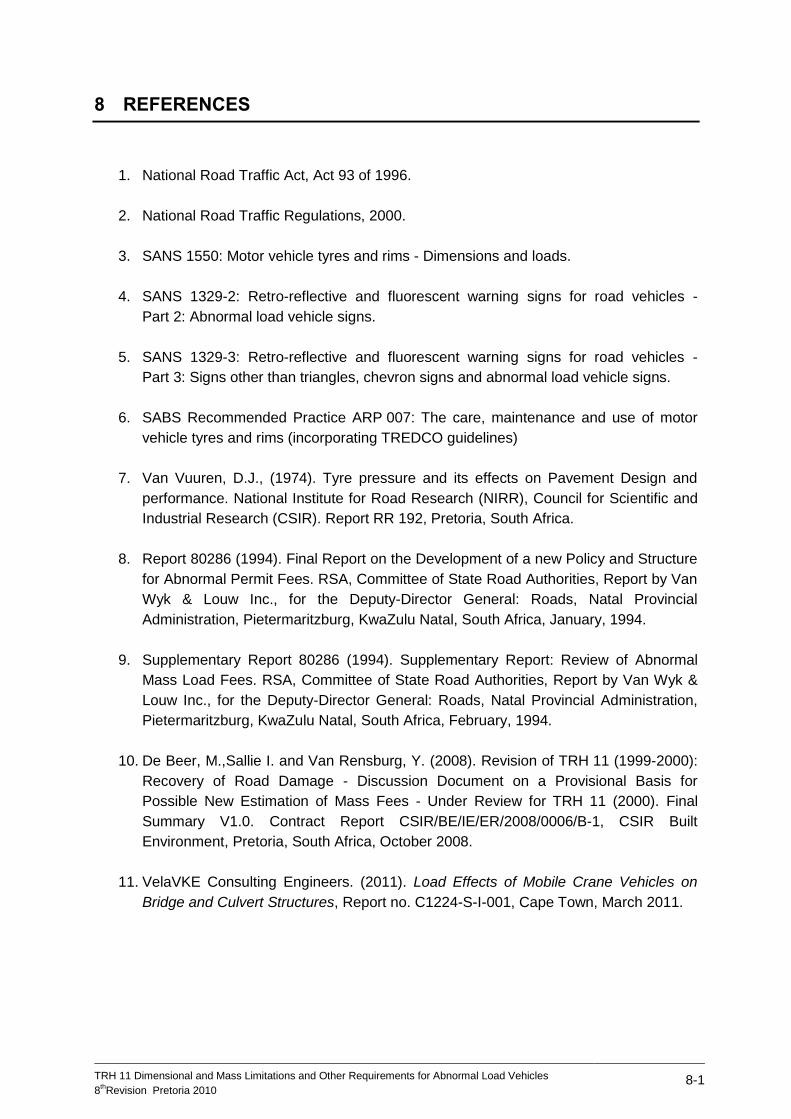
TRH 11 Dimensional and Mass Limitations and Other Requirements for Abnormal Load Vehicles
8thRevision Pretoria 2010
8-1
8 REFERENCES
1. National Road Traffic Act, Act 93 of 1996.
2. National Road Traffic Regulations, 2000.
3. SANS 1550: Motor vehicle tyres and rims - Dimensions and loads.
4. SANS 1329-2: Retro-reflective and fluorescent warning signs for road vehicles -
Part 2: Abnormal load vehicle signs.
5. SANS 1329-3: Retro-reflective and fluorescent warning signs for road vehicles -
Part 3: Signs other than triangles, chevron signs and abnormal load vehicle signs.
6. SABS Recommended Practice ARP 007: The care, maintenance and use of motor
vehicle tyres and rims (incorporating TREDCO guidelines)
7. Van Vuuren, D.J., (1974). Tyre pressure and its effects on Pavement Design and
performance. National Institute for Road Research (NIRR), Council for Scientific and
Industrial Research (CSIR). Report RR 192, Pretoria, South Africa.
8. Report 80286 (1994). Final Report on the Development of a new Policy and Structure
for Abnormal Permit Fees. RSA, Committee of State Road Authorities, Report by Van
Wyk & Louw Inc., for the Deputy-Director General: Roads, Natal Provincial
Administration, Pietermaritzburg, KwaZulu Natal, South Africa, January, 1994.
9. Supplementary Report 80286 (1994). Supplementary Report: Review of Abnormal
Mass Load Fees. RSA, Committee of State Road Authorities, Report by Van Wyk &
Louw Inc., for the Deputy-Director General: Roads, Natal Provincial Administration,
Pietermaritzburg, KwaZulu Natal, South Africa, February, 1994.
10. De Beer, M.,Sallie I. and Van Rensburg, Y. (2008). Revision of TRH 11 (1999-2000):
Recovery of Road Damage - Discussion Document on a Provisional Basis for
Possible New Estimation of Mass Fees - Under Review for TRH 11 (2000). Final
Summary V1.0. Contract Report CSIR/BE/IE/ER/2008/0006/B-1, CSIR Built
Environment, Pretoria, South Africa, October 2008.
11. VelaVKE Consulting Engineers. (2011). Load Effects of Mobile Crane Vehicles on
Bridge and Culvert Structures, Report no. C1224-S-I-001, Cape Town, March 2011.
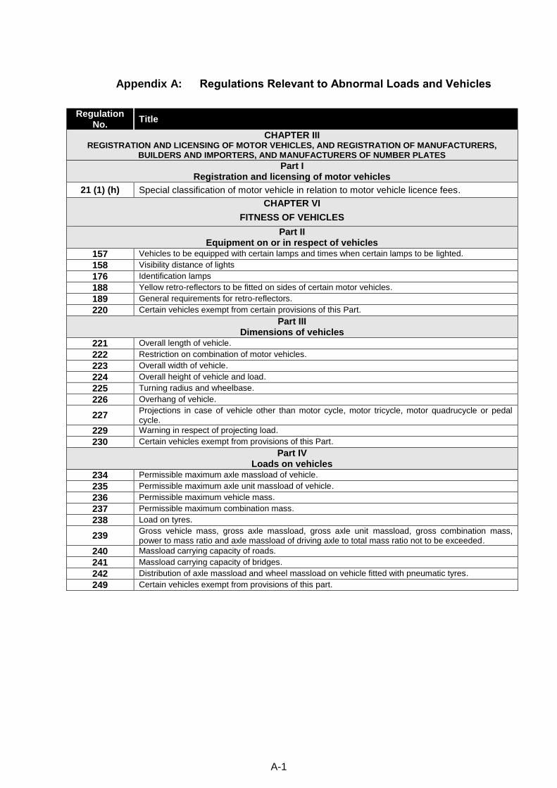
A-1
Appendix A: Regulations Relevant to Abnormal Loads and Vehicles
Regulation No.
Title
CHAPTER III REGISTRATION AND LICENSING OF MOTOR VEHICLES, AND REGISTRATION OF MANUFACTURERS,
BUILDERS AND IMPORTERS, AND MANUFACTURERS OF NUMBER PLATES
Part I Registration and licensing of motor vehicles
21 (1) (h) Special classification of motor vehicle in relation to motor vehicle licence fees.
CHAPTER VI
FITNESS OF VEHICLES
Part II Equipment on or in respect of vehicles
157 Vehicles to be equipped with certain lamps and times when certain lamps to be lighted.
158 Visibility distance of lights
176 Identification lamps
188 Yellow retro-reflectors to be fitted on sides of certain motor vehicles.
189 General requirements for retro-reflectors.
220 Certain vehicles exempt from certain provisions of this Part.
Part III Dimensions of vehicles
221 Overall length of vehicle.
222 Restriction on combination of motor vehicles.
223 Overall width of vehicle.
224 Overall height of vehicle and load.
225 Turning radius and wheelbase.
226 Overhang of vehicle.
227 Projections in case of vehicle other than motor cycle, motor tricycle, motor quadrucycle or pedal cycle.
229 Warning in respect of projecting load.
230 Certain vehicles exempt from provisions of this Part.
Part IV Loads on vehicles
234 Permissible maximum axle massload of vehicle.
235 Permissible maximum axle unit massload of vehicle.
236 Permissible maximum vehicle mass.
237 Permissible maximum combination mass.
238 Load on tyres.
239 Gross vehicle mass, gross axle massload, gross axle unit massload, gross combination mass, power to mass ratio and axle massload of driving axle to total mass ratio not to be exceeded.
240 Massload carrying capacity of roads.
241 Massload carrying capacity of bridges.
242 Distribution of axle massload and wheel massload on vehicle fitted with pneumatic tyres.
249 Certain vehicles exempt from provisions of this part.
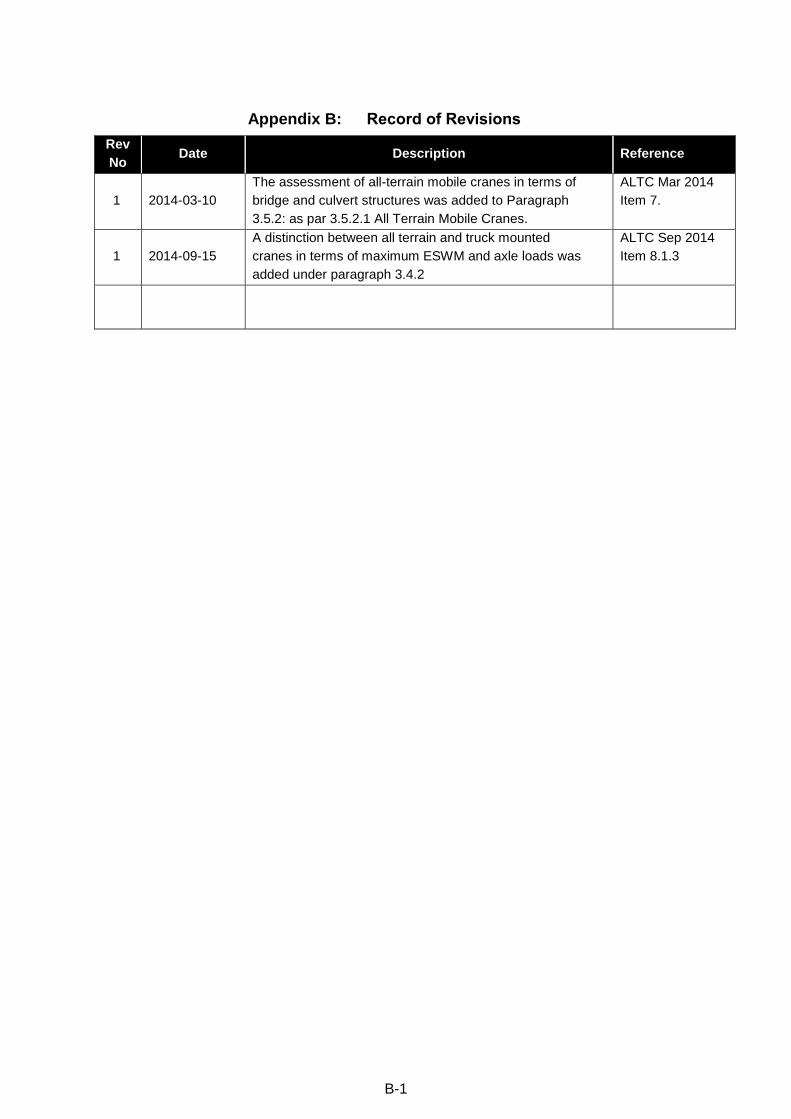
B-1
Appendix B: Record of Revisions
Rev
No Date Description Reference
1 2014-03-10
The assessment of all-terrain mobile cranes in terms of
bridge and culvert structures was added to Paragraph
3.5.2: as par 3.5.2.1 All Terrain Mobile Cranes.
ALTC Mar 2014
Item 7.
1 2014-09-15
A distinction between all terrain and truck mounted
cranes in terms of maximum ESWM and axle loads was
added under paragraph 3.4.2
ALTC Sep 2014
Item 8.1.3

![Highly time-resolved two-dimensional mapping of the ...Distance between PBL and µ-probe [mm] mass 94 Phenol mass 92 Toluene mass 78 Benzene mass 34 H 2 S mass 30 NO mass 17 NH 3 pyrolysis](https://static.fdocuments.net/doc/165x107/5e5453d8ddf4d135874d62eb/highly-time-resolved-two-dimensional-mapping-of-the-distance-between-pbl-and.jpg)


