TRENDWALL MOVABLE WALL PLANNING GUIDE · PDF fileTRENDWALL‰ MOVABLE WALL PLANNING...
33
TRENDWALL ‰ MOVABLE WALL PLANNING GUIDE
Transcript of TRENDWALL MOVABLE WALL PLANNING GUIDE · PDF fileTRENDWALL‰ MOVABLE WALL PLANNING...
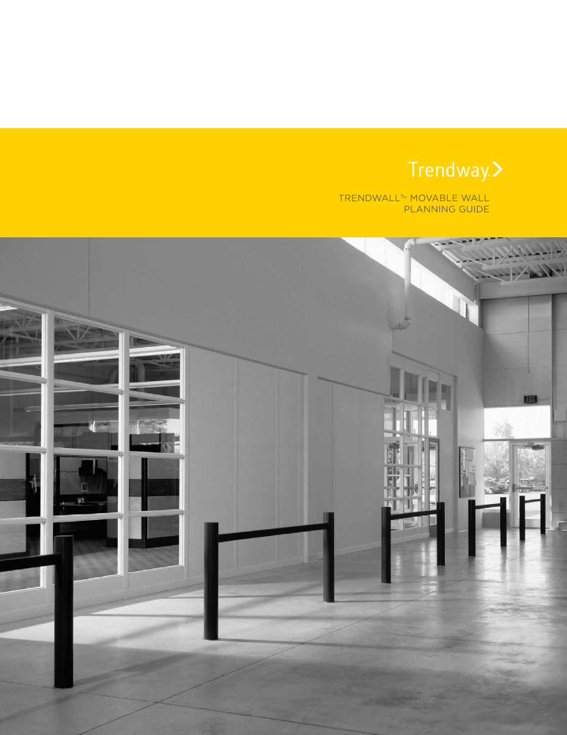
TRENDWALL‰ MOVABLE WALLPLANNING GUIDE
2
ContentsSix steps to specification ...........................................................................3
Design and Installation Planning ........................................................4-8
Components ...........................................................................................9 - 12
Framing Elements ...................................................................................... 10
Panels .......................................................................................................11 - 15
Door Sections ...................................................................................... 16 - 18
Doors ...................................................................................................... 18 - 19
Door Hardware .............................................................................................19
Conditions ........................................................................................... 20 - 23
Pilasters .................................................................................................23 - 24
Accessories ...................................................................................................25
Power and Data .................................................................................26 - 27
Electrical Planning ........................................................................... 28 - 29
Acoustics ............................................................................................. 30 - 31
Installation Note .........................................................................................32

3
TrendWall‰ Movable Wall
Proven for Nearly 50 Years
For nearly 50 years, TrendWall Movable Walls have been used in floor-to-ceiling applications
around the world. Its simple installation minimizes downtime and practically eliminates mess
and waste. It can be rapidly reconfigured without demolition, using only a handful of trades. A
proven performer, TrendWall responds with ease to support an organization’s changing needs.
TrendWall offers flexible architectural planning, expanded capacity for utility and technical
infrastructure, and integration with both existing building infrastructure and systems furniture.
With a broad palette of standard surface materials and finishes, plus the ability to support a
wide range of custom and special materials, TrendWall can seamlessly harmonize throughout
an environment.
TrendWall is BIFMA level® 2 certified and with SCS Indoor Advantage Gold™ certified compo-
nents. TrendWall, Volo‰ and Clear Wall are the premier sustainable architectural walls on the
market.
Six steps to specs:
1. Pre-qualify the project
2. Select Panel types
3. Select Door Section
4. Specify Conditions Connectors
5. Specify Electrical and Data components
6. Specify Accessories and Miscellaneous Components/Connectors
4
Design and Installation PlanningProper planning and preparation is key to successful and profitable TrendWall projects. Be-gin by taking the time to fully understand the customer’s needs and requirements. Have their Request for Bid documentation on hand when performing site surveys and during design and installation. It is critical to document all decisions made from start to finish.
Trendway field support
Trendway offers Field Technical Support for a nominal fee. Certified Trendway Technicians can take field measurements, train and assist during the actual installation at the customer location. Using this resource assures accurate product design and planning, as well as fast, expert instal-lation. Contact the Trendway Architectural Product team for more details.
Getting Started
• TrendWall measurements are based on centerline-to-centerline locations (e.g., center panel to center panel vs panel edge to panel edge).
• Begin by defining the location of the partition run. TrendWall Vertical Connectors are 2-3/4" thick, so using construction lines that are offset by 1-3/8" is a good place to start (center of panel). Wall Starts and condition connectors are consistently 2-3/4" thick.
• Once the desired location of the walls is determined, you can begin the office layout.• The framing layout and elevations can be developed using 20/20 CAP planning software
supported with Trendway symbol libraries.
Site survey and verified field measurements
• A thorough pre-installation survey is required.• Ensures fast, accurate, effective space planning and design.• Allows effective scheduling for timely completion, no lost time on the job. • Improves profit through problem-free installations, happy customers and return business.
Floor plansAccurate floor plans with key dimensions and conditions within the building architecture are es-sential. They should include:• Overall space dimensions• Wall locations and distance from columns• Wall runs that terminate flush with building wall surfaces• Existing corridor widths and runs that bypass building columns

5
Site Ceiling
Determine the installation site's ceiling type and grid (if applicable), which will determine attach-ment requirements. If you are not certain, or encounter a different type of ceiling than those described here, send a photo to your Trendway Technical Support team for assistance.
Information you will need:
• Identify ceiling type: Grid and Tile, Gypsum and/or other material (e.g. wood). This will determine the type of ceiling anchors you require.
• Identify Grid Ceiling Tile type (if applicable): - Flat - Tegular/Reveal.
• Tegular/Reveal grids require the use of Grid Blocks for installation. Determine if the Tegular tile has a 1/4" or 3/8" tile recess dimension (di-mension it sits proud of the grid). There are Grid Blocks for Traditional and Reveal style crowns. Specify the 1/4" or 3/8" Block, depending on the tile recess. Specify one Block for every 2' of panel run, or 6 for every Crown section on order.
• Identify Grid type (if applicable): 1" Standard or 9/16" Thinline
Caddy Clips may be used to attach the Crown to a ceiling grid. Use one every 2' of Crown. Caution: There will be a loss of 1/2" to 5/8" ceiling height adjustment when using Caddy Clips.
Flat Lay-In Tile Grid
Tegular/Reveal Tile Grid
Tegular/Reveal Tile
Flat Tile
Grid Block Installed
Ceiling height – a critical measurement• Measurements must be taken on the final
site floor treatment (after carpet or other flooring is installed) for accuracy.
• IMPORTANT: Measure ceiling height at every door location.
• Measure ceiling heights every 10', approxi-mately along the line the wall will run.
• If there is variance greater than 1/2" over a 10' measurement, take additional measure-ments at 5' intervals.
• Provide minimum and maximum heights.
• Note all heights accurately on the floor plan in 1/8" increments.

6
Physical building conditions
Site conditions may affect wall placement or require special planning to accommodate. In-spect the site and note any situations that may impact or interfere with the layout, such as:
• Building walls and columns• Building electrical and data access• Convector Units (baseboard heating units)• Perimiter Wall Start Conditions• Air-handling diffusers• Floor Type HVAC Supply and Return Grills• Light fixtures• Soffits• Sprinkler heads• Unusual Baseboard Configurations• Wall or floor outlets• Window Fillers• Ceiling type• Flooring type• Window sill and drapery pockets
Once the site observation and measurements are complete:
• Identify any design modifications that should be anticipated due to site conditions. • Review modifications with the designer before any design or layout begins• Review modifications with the installers before installation work begins.
Once the design is finalized, it’s essential to do a thorough onsite verification of the installation drawings to actual site dimensioning prior to installation.
Compliance with relevant regulations
Before any work is preformed, be certain you are in compliance with local and/or Government project or contract regulations. These may include, but are not limited to:
• Building Codes• Building Permits• Test data or product sample submissions for approval• Certificates of Occupancy• Labor requirements (security clearance, trade union jurisdictions for tasks, etc.)• Dealer- or customer-supplied verification of seismic bracing if required by local code

7
TrendWall Office Layout
When designing your layout, it is best to work in standard dimensions of even footage. An example is shown in the sample layout (Figure 1): 15' by 10'.
An important consideration is the cost of the different panel types and sizes. The most cost-efficient size is the 4'-wide panel. It takes less time to install 12 lineal feet of 4' panels than 12 lineal feet of 2' panels. Also, for future changes, standard width panel modules will make modi-fications easier.
The first step is to measure the perimeter dimension of the space to be enclosed. Be sure to measure through door sections and glazed panels. This represents the total footage of Trend-Wall panels required.
Panel widths are based on center-to-center of the connection device so there is no addition of width in a straight line connection. TrendWall panels are 2-3/4" thick. Half this thickness, (1-3/8") must be added to the length of the panel run for an outside dimension, or subtracted for an inside dimension when panels are joined in a 90° corner condition (Figure 2).
Once you have decided the amount of space and the components desired, you will need to figure the widths of panels needed to achieve your office plan. Notice that we have used two 4'- wide panels to accommodate the Lateral Files side-to-side (Figure 1). 1'-wide panels on ei-ther end of that wall make up the rest of the 10' width and center the components on the wall. Minimum width panel available is 6".
Component PlanningMany of Trendway's Choices panel-hung components can be mounted on TrendWall panels. (NOTE: Work Surface may not be mounted on TrendWall.) Components can be mounted on floor-to-ceiling panels only. Component Mounting Kits are used for Straight Panel conditions and attach between panels without adding to the panel run width. Component Mounting Kits contain two vertical rows of slots to 84" high. Two kits are required to hang one component. Two components can be hung side-by-side on three Mounting Kits (Figures 1 and 3).
48"48"
48"
48"
48"48"48"
48"
48"
12"
12"
48"
10'-0"
15'-0"
36"
36"
24"•
•
••
Figure 1
Figure 2
•• 4'
•• 8'-1³⁄8"
CL CL
CL
Figure 3
2" • •

8
Installation planning checklist
___ Where will material be received, and who will receive?
___ Where will material be stored?
___ Are there any access or security rules governing time that installation may take place?
___ Where are walls to be installed?
___ Is the environment (i.e. heat, light, humidity, etc.) satisfactory?
___ Are there any power complications?
___ Are there any material handling obstacles (e.g. elevator/stairwell/corridor dimensions)?
___ What preparation is required for cleanliness of metal trim and panel cutting?
___ Are there any special tools or equipment required?
___ Are there complications or timing conflicts with other trades?
___ Are flooring-loading limitations satisfactory?
___ Ceiling type (drywall, drop Flat, drop Tegular/Reveal etc.)?
___ Is there anything on this job that requires extraordinary preparation?
Post-Installation
• Obtain post-installation verification of product delivery, ownership, and security.
• Complete any punch list items and “turnover” procedures (Certificate of Occupancy, etc.).
• If promotional photography is desired, obtain permission (signed release) and schedule.
9
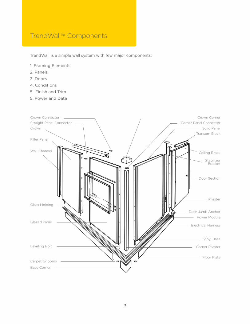
TrendWall‰ Components
Wall Channel
Straight Panel Connector
Crown Connector
Crown
Filler Panel
Glass Molding
Stabilizer Bracket
Ceiling Brace
TrendWall is a simple wall system with few major components:
1. Framing Elements
2. Panels
3. Doors
4. Conditions
5. Finish and Trim
5. Power and Data
Base Corner
Glazed Panel
Leveling Bolt
Carpet Grippers
Corner Panel Connector
Crown Corner
Solid Panel
Transom Block
Electrical Harness
Pilaster
Door Section
Door Jamb Anchor
Power Module
Corner Pilaster
Vinyl Base
Floor Plate
10
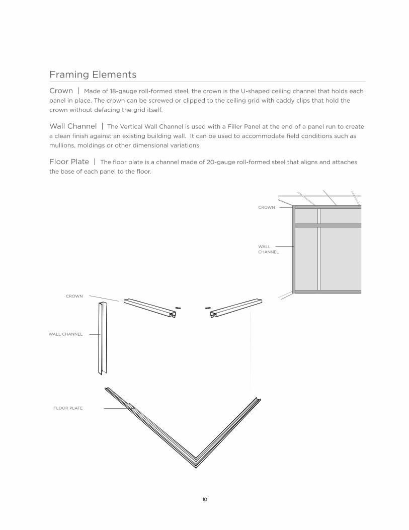
Framing Elements
Crown | Made of 18-gauge roll-formed steel, the crown is the U-shaped ceiling channel that holds each
panel in place. The crown can be screwed or clipped to the ceiling grid with caddy clips that hold the
crown without defacing the grid itself.
Wall Channel | The Vertical Wall Channel is used with a Filler Panel at the end of a panel run to create
a clean finish against an existing building wall. It can be used to accommodate field conditions such as
mullions, moldings or other dimensional variations.
Floor Plate | The floor plate is a channel made of 20-gauge roll-formed steel that aligns and attaches
the base of each panel to the floor.
CROWN
WALL CHANNEL
FLOOR PLATE
WALL CHANNEL
CROWN

11
Panels
Panel Height | TrendWall panels are categorized in three standard heights, 8' and less, 9' and less, 10'and less. Within those sizes they can be specified in 1/8" increments for dimensions from 7' to 10' high. Ceiling Panels and Blocks can also create additional height (see below) TrendWall panels have an adjustable base that accommodates adjustment 3/4" up or 3/4" down. Specify ceiling height in inches using a decimal to represent fractions in eighth-inch increments.
Panel Width | TrendWall panels are available in 1/8" increments from 6" to 4' wide. The most cost- efficient panel is 4' wide. Specify panel width in inches using a decimal to represent fractions in eighth- inch increments.
SOLID PANELFILLER PANEL
GLAZED PANEL
48" Max.
84" Min.
120" Max.
6" Min.
PANEL/FILLER PANEL WIDTH1/8" Increments
PANEL/WALL FILLER PANEL
HEIGHT1/8" Increments
CEILING FILLER PANEL HEIGHT1/8" Increments
12" Min.
48" Max.
168" Combined Max.

12
Solid Panels | Solid panels are fabric or vinyl clad 3/8" gypsum surface, available in a wide variety
of fabrics and vinyl, or may be specified with Customer’s Own Material (COM). Panels can be specified
with vinyl on one side and fabric on the other. All visible metal surfaces on the panel are finished with
powder-coated paint, available in all standard Trendway trim color options. See the Surface Material
pages of the current Price List for detailed surface material options.
Filler Panels | Filler panels are installed at the end of a panel run that meets a fixed wall. They
accommodate window mullions, moldings, uneven wall conditions and irregular shaped conditions.
Available in 6" to 48" widths in 6" increments, Filler Panels have a steel side rail on one end and an
expanded polystyrene core that can be cut to fit conditions in the field. Wall Channel must be ordered to
provide a clean finished transition to the building wall (part number TWC##). One wall channel should
be ordered for every Filler Panel. A Ceiling Filler Panel is constructed identically to the corresponding
Filler Panel below it.
Ceiling Panels | In addition to the maximum 10' Panel height, Ceiling panels and Ceiling Filler Panels can add another 1' to 4' in height. Ceiling Panels are constructed using a welded steel frame with a thermafiber core and 3/8" (10) gypsum wall-board skins that can be laminated with vinyl or fabric. The minimum ceiling panel
height is 1'.
NOTE: Ceiling Panels and Ceiling Filler Panels may not be used with component mounting. Ceiling Braces must be used at every door section and every 8' in the panel run.
Solid Panel Louver OptionsAluminum painted louvers can be added to any
Solid Panel at least 36" wide. The Louver opening is
11" x 27". Louvers are powder-coat painted to match
the chosen Trim Color.
P0 - No OpeningP1 - Aluminum Louver Top P2 - Aluminum Louver Bottom
SOLID PANELWALL FILLER PANEL
CEILINGFILLER PANEL
CEILING PANEL
NO OPENING BOTTOM LOUVER TOP LOUVER

13
Glazed Panels | TrendWall Glazed Panels are constructed using the same welded frame and core materials as the TrendWall Solid Panels, but also include a framed opening These panels are roll-formed steel frames with 22-gauge vertical and horizontal glass rails and dual durometer vinyl glass retainers that hold a 1/4"-thick sheet of tempered safety glass or other approved glazing material. Glazing can either be provided by Trendway or by a local supplier. A complete glass schedule is provided for all orders that ship without glass.
Basic Glazed Panels DO NOT come with any glass or glass alternative from Trendway. There are, however, numerous ways to glaze TrendWall Glazed Panels, including a factory direct option. Options include:
• GN – No Glazing provided.
• G1 – 3form Ecoresin® – The maximum cut size for any 3form material is 74", which means that it cannot be used in Full Height, Single opening panels. - T01 Solo Supermatte - T02 Aqua Solo Supermatte - T03 Spider
• G2 – Tempered Glass.
• G3 – Tempered Glass options: - T04 Frosted - T05 Clear Laminated
TrendWall Glazed Panels are available with a variety of opening sizes and locations:
• Full Lite - the opening begins a minimum 9-1/4" from the bottom of the panel and ends 2-1/4" from the top.
• Door Height - the opening begins a minimum 9-1/4" from the bottom of the panel and ends at the chosen door height (80" or 84")
• Window Lite - the opening begins at 42-1/2" from the bottom of the panel and ends at door height.
• Hi Lite - the opening begins at the door height (80" or 84") and ends 2-1/4" from the top of the panel.
FULL LITE WINDOW LITE DOOR HEIGHT HI LITE SEGMENTED SEGMENTED FULL LITE (S5) DOOR HEIGHT (S4)
DOOR HEIGHT
DOOR HEIGHT
DOOR HEIGHT
DOOR HEIGHT

14
Glazed Panel Louver Option
Aluminum painted louvers can be added to any Glazed Panel at least 36" wide. The Louver opening is
11" x 27". Louvers are powder-coat painted to match the chosen Trim Color.
• P2 - Aluminum Louver Bottom
Segmented Glazed PanelFull Lite and Door Height Glazed panels have the ability to become Segmented by simply selecting the base panel style and specifying the number of segments in the Glazed Segment option string.
S1 - 1 OpeningS2 - 2 OpeningS3 - 3 OpeningS4 - 4 OpeningS5 - 5 Opening
Example: To obtain a Full Lite panel with two segments, choose catalog number WPGF and add option S2.
Glazed Ceiling PanelGlazed Ceiling Panels are constructed using a welded steel frame with a thermafiber core with a framed opening to accommodate 1/4" glazing material. They are used in conjuction with lower panels to reach ceiling heights greater than 10'. NOTE: Glazed Ceiling Panels may not be used with component mounting. Ceiling Braces must be used at every door section and every 8' in the panel run.
GLAZED CEILING PANEL
SEGMENTED GLAZED PANEL

15
Variable Glazed Panel with Custom SegmentsTrendWall Variable Glass Panels with Custom Segments allow specifiers to select a different height, placement and glazing material for each individual segment in a panel. This is especially useful for designs requiring a segment of non-transparent material to provide a degree of privacy, or to create a special sill height.
Customers can choose up to 5 segments per panel. Different catalog numbers apply according to the number of segments desired. Segments are specified as S1, S2, S3, S4, S5 as required, with the lowest segment in the panel always S1, the next lowest S2, etc. up to S5.
There are three basic categories of Variable Glass Panels with Custom Segments: Full Height, Door Height with Top Glass and Door Height with Top Solid. Example: To obtain a Full Lite panel with two segments, choose catalog number WPGF and add option S2.
Full Height Panels Door Height Panels — Top Glass Door Height Panels — Top Solid
S1
S2
S3S4
S5
In order to specify these panels, you will need to determine the following:
1. Panel type from the 3 options above
2. Ceiling height
3. Panel width
4. The Sill height (minimum 9.25”)
5. Glass Size Pricing Category for each section (8 categories, 1A – 1H, depending on the size)
6. The position (height) of each glass line, measured from the finished floor level
7. The height of the top of the last upper segment (ceiling ht. minus 3.5”).
Catalog numbers for variable glass panels with custom segments will begin with one of the following:
WPGV__, WPGVF__, WPGVD__, and end with S1, S2, S3, S4 or S5.
To easily determine the Glass Size Pricing category, use the Variable Panel Worksheet, located in the
Products/Specifications – Training section of Trendealer, under the Architectural Products category.
This easy-to-use tool will generate the category for each segment to simplify final specification. Click
here to see it now.
Ceiling Height
Height of each glass line and the top
Glass Size Pricing for each section
Sill Height (min. 9.25")
Panel Width

16
Doors
Door Sections | Standard doors are vinyl or HPL surfaced, 3' by 6'8" or 7' by 1-3/4"-thick hollow core. Door Panels are shipped with doors pre-hung in steel jambs with hinges and Lever Passage set. Six standard swing door styles are available: Flush, Flush with Standard Louver, Half Lite, Half Lite with Louver, Vision Lite, or solid core door with Full Lite (glass is shipped separately or sourced locally). Optional doors and hardware may be specified by contacting Trendway Customer Care at 1-866-584-0201. Doors and Transoms are also available in special finishes. Note: glass molding and louvers match specified trim color. Doors can also be ordered separately.
Door Section Heights: Available in a variety of sizes to accommodate openings from 7' to 10' in height. Specify actual ceiling height in inches, using a decimal to repreent fractions in 1/8" increments.
Door Section Widths:• Standard Swing Door Section Width – 48" (including 8" side panel)• Minimum Swing Door Section Width – 40" (no side panel) • Double Swing Door Section Widths – 72" and 84"• Standard Sliding Door Section Width – 48" (including 8" side panel) • Minimum Sliding Door Section Width – 40" (no side panel) • Bi-Fold Door Section Widths – 48", 60" and 72"
Note: For conference rooms over 150 s.f. in size or any class room that holds 10 people or more, swing doors are typically required to meet national access and egress codes.
STANDARD SWING DOOR SECTION
MINIMUM DOOR SECTION
RIGHT-HAND SLIDING DOOR SECTION
DOUBLE SWING DOOR SECTION
BI-FOLD DOOR SECTION
Panel Surface Color
Door Surface Color

17
Swing Door Sections
TrendWall Door Sections are available in two styles: Standard Door Sections and Minimum Door Sections. Standard sections have an 8" side panel and are nominally 48" wide. Minimum sections do not have a side panel and are nominally 40" wide. Both can be specified with a factory pre-hung door, or without a door if they will be purchased locally. The door height must be specified when ordering Door sections, either 6'8" or 7'. As with TrendWall panels, you have the option of door sections with vinyl on one side and fabric on the other. NOTE: All Doors are ADA compliant, with a 32" clear opening.
Door sections include a transom. Transoms can be specified solid, glazed or with painted metal louver. They may be vinyl or fabric covered. Side panels are also vinyl or fabric covered. Doors themselves must be finished the same on both sides.
Note: Glazed Transoms are NOT available in any fabrics.
Note: Glazed and louvered Transoms are ONLY available in ceiling heights greater than 8' 4".
Sliding Door Sections
Sliding Door Sections are available as a space saving alternative
to standard swing doors. They share the same 48" (1219) rough
opening as standard door sections and have most the same
options. The main difference, other than the door function, is that
these doors need to be field installed.
The doors can be specified as either LH or RH. The hand is
determined by the direction the door slides to open. A RH door
will open to the user’s right when facing an exterior mounted
door. ADA compliant Sliding Door Pulls come with a Satin
Chrome finish. Specify actual ceiling height in inches using a
decimal to represent fractions in one quarter inch increments.
Double Swing Door Sections
Double Swing Door Sections create a 72" opening by using one active door (the door with lever set) and one
passive inactive door (the door with no lever set). Double Door Sections have the same factory options as
Standard Doors, however, these doors require field assembly. Door panels, headers, jambs and hardware are
all sent separately.
Specify actual ceiling height in inches using a decimal to represent fractions in one quarter inch increments.
Bi-Fold Door Sections
Bi-Fold Door Sections can create a variety of storage areas within TrendWall installations. Bi-Fold sections
come in only the flush door style with solid transoms. Like Double Door Sections, Bi-Fold Door Sections
requires field assembly. Specify actual ceiling height in inches using a decimal to represent fractions.
Note: The actual bi-fold door opening is 12" less than the nominal door section.
Side 1Side 1
Side 2 Side 2
Right-Hand Swing Left-Hand Swing
Right-Hand Slide Side 2
Outside Side 1
Left-Hand Slide Side 2
Outside Side 1

18
Standard Single Door Standard single doors are 3' wide by 6'8" or 7' high by 1-3/4" thick. Specify left-hand or right-hand swing.
Windows can be specified in a variety of sizes and shapes.
Double DoorDouble doors feature one active door and one inactive door, which is kept closed by a latch on the edge
near the top and bottom. Unlocking the latch allows both doors to open, creating a 6' wide entrance. Field
assembly is required.
Door GlazingThere are numerous ways to glaze TrendWall Doors, including a factory direct option. All are field-installed.
SWING DOORS:
• GN (No glass). If this option is chosen, no glass will be supplied. All 1/4" (6) material will need to be field installed. Trendway will supply a detailed glass schedule to facilitate this process.
• G1 – 3form Ecoresin Glazing Alternative
• G2 – Clear Tempered Glass
• G3 – Tempered Glass options: Frost and Clear Laminated
SLIDING DOORS:
• GN (No glass). If this option is chosen, no glass will be supplied. All 1/4" (6) material will need to be field installed. Trendway will supply a detailed glass schedule to facilitate this process.
• G1Z – Tempered Glass
• G3Z – Tempered Glass options: Frost and Clear Laminated
• G5Z – 3form Ecoresin Glazing Alternative
FLUSH DOOR FLUSH DOORWITH LOUVER
VISION LITE VISION LITEAND LOUVER
WINDOW LITE LITEAND LOUVER
FULL LITE
TRENDWALL FLUSH SLIDING DOOR,
TRENDWALL FULL LITE SLIDING DOOR,
DOUBLE DOOR

19
Bi-Fold Door Panels | Ideal for storage, bi-fold doors are double doors hinged in the middle to fold out of the way as they open. Field assembly is required. Bi-Fold Doors ship complete with 1-1/8" spherical brushed chrome knobs.
Note: The actual bi-fold door opening is 12" (305) less than the nominal door section.
Door Hardware | Swing Doors can be specified with no door hardware (NH) but come standard with an ADA compliant Passage Lever Set. A locking version can be specified at an upcharge. Sliding Doors come with 18" Post Pulls. Door Hardware can be purchased separately.
BI-FOLD
SWING DOOR PULL
ADA Lever Set
Lever Lockset shown, non-interchangeable lock, Brushed Chrome finish.
Passage Set available.
SLIDING DOOR PULL
18" Post Pull, Satin Chrome finish. 12" centerline to centerline of mounting hardware.
Door Size Style Lite Size (1/4" thick)
3' x 6' 8" x 1-3/4"
Full 24" x 66"Window 26” x 34”
Vision 4” x 34”
3’ x 7’ 8” x 1-3/4”Full 24” x 70”
Window 26” x 38”Vision 4” x 38”

20
TrendWall ConditionsTrendWall Conditions are the connector kits that join individual panels together. These conditions include all necessary trim pieces and hardware to trim out and connect a TrendWall installation. Conditions may be specified in one of two possible styles: Standard and Enhanced. Standard pilasters are designed to fit flush within the panel run and reveal the panel's side rail, while Enhanced pilasters mount over the panel connection and cover the side rails to give a more monolithic aesthetic.
Connectors | TrendWall has one piece connectors that slide into slots in the panel's side rails. Connectors are designed to accommodate the laying-in of electrical and communications wiring while still allowing the removal of the panel without disturbing the wiring. All panels are shipped with the connectors required for attaching one panel to another.
Corner Connectors will be included for each corner condition that is specified in the panel layout. If the layout requires angles other than 180° or 90°, you can specify the angle required on the order form. Where special requirements are needed, you should send a copy of the layout along with your order, noting the areas requiring special conditions. There will be an extra charge for these special conditions.
Extended and Half-Extended Corner Connectors are required for use with Corner Component Mounting Rails.
Straight Conditions | These conditions include two straight pilasters and panel connectors and are used to make an inline panel connection. Straight Conditions are available in both standard and enhanced versions. They can also be ordered with Choices Component Mounting Kits and/or electrical punch-outs to accommodate either hardwire or modular power. Specify actual ceiling height in inches using a decimal to represent fractions in one quarter inch increments.
Corner Conditions | Corner Conditions include one outside corner pilaster cover, panel connectors, one crown corner and one base cover. Corner Conditions are used to create 90° corner in panel runs. Corner Conditions are available in both Standard and Enhanced versions. Note: Corner Conditions maintain centerline dimensioning.
Enhanced Extended Corner ConditionsExtended Corner Conditions include one outside corner pilaster cover, one inside corner pilaster, panel connectors, one crown corner and one base cover. Extended Corner Conditions are used to create a 90° corner in panel runs. Extended Corner Conditions are available in the Enhanced version only.
Note: Extended Conditions allow for inside room dimensioning (rather than center line dimensioning). Using Extended Conditions allow for standard sized freestanding furniture to fit within TrendWall layouts without increasing panel sizes.
Standard Pilaster
Straight Connector
Standard Straight Pilaster (2)
•
•
Straight Connector
EnhancedStraight Pilaster (2)
•
•
Standard Straight Enhanced Straight Top View
Side 1
Side 2
Crown Corner
Corner Connector
Standard Outside Corner Pilaster
Base Corner
•
•
•
•
Crown Corner
ExtendedCorner Connector
Enhanced Outside Extended Corner Pilaster
Base Corner
•
•
Enhanced Inside Corner Pilaster•
•
•
Crown Corner
Corner Connector
Enhanced Outside Corner Pilaster
Base Corner
•
•
•
•
Standard Enhanced

21
Angled Conditions | TrendWall allows specification of a standard 90° 2-way condition, plus virtually any angle within 72° of a straight in-line condition, as shown in the drawing. As with standard 90° 2-way conditions, the Standard Angle Condition (WCSAXX) comes with a mating crown corner (24" leg length). The service items (SITWCSAXX) do not include the mating crown corner. 30, 45 and 60 degree angled conditions do not require a drawing to be submitted; however, when specifying angled conditions other than 30, 45 or 60, a detailed scale drawing must be submitted.
Angled Wood BlocksAngle Wood Blocks are available for attaching panels to a fixed wall at an angle other than a 90°. Detailed scaled drawings must be submitted when ordering.
3-Way Conditions | 3-Way Conditions, commonly called “T” conditions, are used to create a 3-way panel connection in panel runs. They can be ordered with Choices component mounting kits to integrate Choices panel hung components. They can also be ordered with electrical punch-outs to accommodate either hardwire or modular power. Punch-Outs are available on the outside face only.
Standard 3-Way ConditionsStandard 3-Way Conditions include one standard straight pilaster cover and panel connectors.
Enhanced 3-Way ConditionsEnhanced 3-Way Conditions include one enhanced straight pilaster cover and panel connectors.
Note: 3-Way Conditions maintain centerline dimensioning.
Standard Half Extended 3-Way ConditionsHalf Extended 3-Way Conditions include one outside straight pilaster cover, two inside corner pilasters and panel connectors. Note: Half Extended 3-Way Conditions create inside dimensioning in one direction..
Enhanced Half Extended 3-Way ConditionsEnhanced Full Extended 3-Way Conditions include one enhanced straight pilaster cover, two enhanced inside corner pilasters and panel connectors. Note: Extended 3-Way Conditions create inside dimensioning in both directions.
Standard Pilaster
Side 1
Side 3
Max 72°STANDARD ANGLED CONDITION
•
•
•
CornerConnector
StraightConnector
StandardStraightPilaster
STANDARD 3-WAY CONDITIONS
CornerConnector
StraightConnector
EnhancedStraightPilaster
••
•
ENHANCED 3-WAY CONDITIONS
Top View
Side 1
Side 2Sid
e 3
EnhancedInside CornerConnector (2)
Extended Corner Connector
Enhanced Straight ExtendedPilaster
•
•
•
ENHANCED FULL EXTENDED 3-WAY CONDITIONS

22
4-Way Conditions | 4-Way Conditions include one steel pilaster, one wall channel and panel connectors. 4-Way Conditions are specified with Trim color only, as only the painted wall channel is seen.
Finished End Kits | Finished End Kits are used to create an end of run that does not abut an existing building element. They can be used in pairs to create archways. One kit includes a painted finished end, one crown cap and two vinyl door base ends. Specify actual ceiling height in inches using a decimal to represent fractions in one quarter inch increments.
Wall Channels | Wall Channels are used with a filler panel at the end of a panel run to create a clean finish against an existing building wall.
Component Mounting Kit | To aid in reconfigurations, TrendWall Component Mounting Kits may be purchased separately from condition kits.
This special conversion assembly allows standard TrendWall panels to accept Trendway's Choices open plan components. The Component Mounting Kit fits in any straight line panel intersection with slotting to 84" (2134) high.
Each slotted bracket contains two vertical rows of slots that are spaced every 1" (25) (on center). Two kits are required to hang one component. Two components can be hung side-by-side on three mounting kits.
The base price includes one slotted cover only. The Component Mounting Kit includes mounting rail, hardware and a slotted pilaster.
Straight Enhanced Pilasters are not recommended for use with Component Mounting Kit.
Only Choices Component Mounting Kits are available.
Note: Cannot be used in panel runs with Ceiling Filler Panels.
Standard Pilaster
Corner Connector
Standard StraightPilaster
• Straight Connector••
• Wall ChannelENHANCED FULL EXTENDED 3-WAY CONDITIONS
FINISHED END KIT FINISHED END KIT
COMPONENT MOUNTING KIT

23
PilastersPilasters are the finished covers designed to snap into place between the panels to conceal the panel connectors and wiring. They come in the same height as panels, ranging from 7'2" to 10' and from 1' to 4' for ceiling fillers. Panels include two matching pilasters, one for each side of the panel. Pilasters are available with optional punchouts for switches, duplex receptacles and data communications.
Pilasters are available in Standard or Enhanced styles and are designed to snap into place between panels to conceal the panel connectors and wiring. Panels include two matching pilasters, one for each side of the panel. Standard punchouts are available. Optional factory modification to pilasters is available to accommodate switches, duplex receptacles and slots for component mounting. Pilasters can be specified with Vinyl, Fabric or any of the standard and premium Trendway trim paint colors. Enhanced Pilasters are available in all vinyl finishes and all fabric colors.
Standard Pilasters | Standard pilasters fit between the panels, exposing the vertical painted side rails of the panels on each side of the Pilaster. Standard Pilasters are available for Straight or Outside Corner Conditions. Standard Pilasters are specified in one of Trendway's standard trim finish colors.
Enhanced Pilasters | Enhanced Pilasters are designed to cover the panel's metal side rails to give a continuous look to the panel run. Enhanced Pilasters are available as Straight, Outside Corner, and Inside Corner configurations. They can be specified in Vinyl or Fabric.
Enhanced Extended Straight Pilasters | Extended Straight Pilasters are available for use with the Extended Corner Connectors, used with Corner Component Mounting Rails. Note: Extended pilasters can be used ONLY with extended conditions and are only available in the Enhanced style.
Corner Pilasters | Corner Pilasters are available in Standard, Enhanced, Extended and Inside Corner styles.
.
STANDARD
OUTSIDE CORNER
Enhanced PilasterStandard Pilaster
ENHANCED OUTSIDECORNER
ENHANCED
EXTENDEDENHANCED STRAIGHT
EXTENDED ENHANCED OUTSIDE CORNER
INSIDE CORNER

24
Punchout Pilasters | Pilasters can be punched to accommodate data communications and electrical
access. Note: Punch-out for Side 1 can not be the same as Side 2 for switch height only.
Punch-out Description:
C0 45" Switch Height with Box
C1 45" Switch Height
C2A 18" Standard Height
C3 32" Work Height
C4 6" Data Height
C5A 18" Standard and 32" Work Height
C6A 18" Standard and 6" Data Height
C7 6" Data and 32" Work Height
C8 Special Punch Out location
AV 72" AV Height
AVC5A 72" AV, 18" Standard and 32" Work Height
AVC6A 72" AV, 6" Data and 18" Standard Height
OUTLET / SWITCH / DATA PUNCHOUT (DECORA)
25
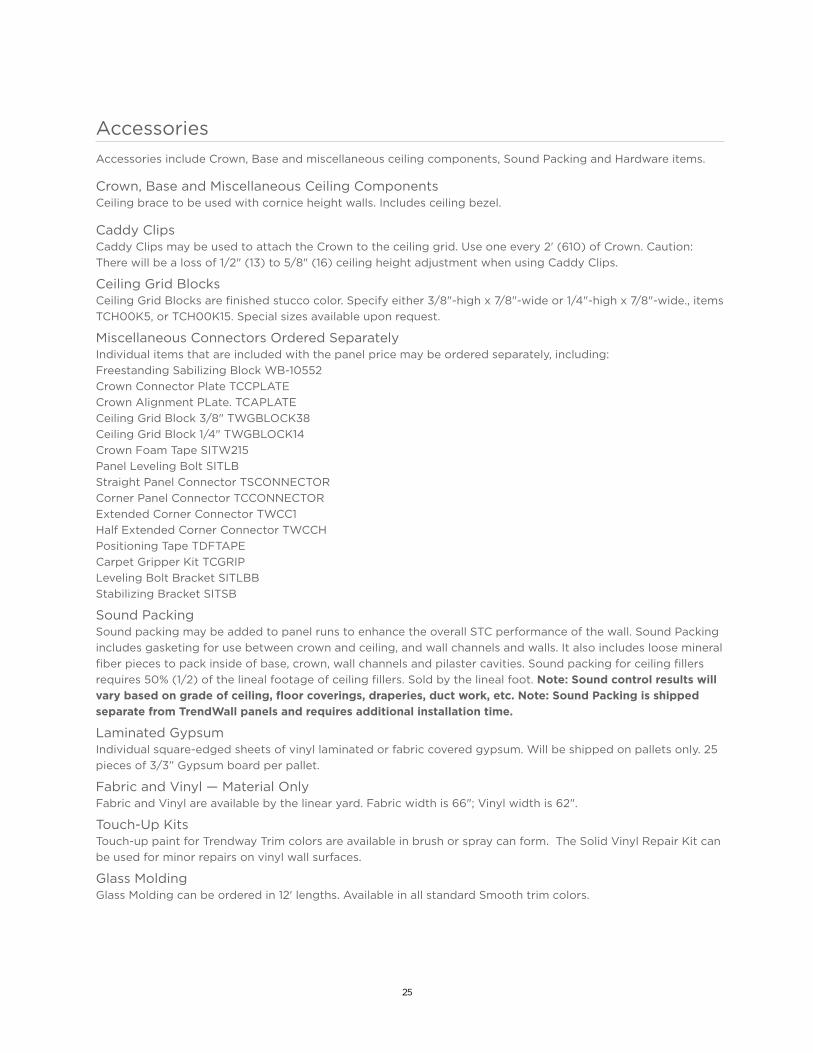
AccessoriesAccessories include Crown, Base and miscellaneous ceiling components, Sound Packing and Hardware items.
Crown, Base and Miscellaneous Ceiling ComponentsCeiling brace to be used with cornice height walls. Includes ceiling bezel.
Caddy ClipsCaddy Clips may be used to attach the Crown to the ceiling grid. Use one every 2' (610) of Crown. Caution: There will be a loss of 1/2" (13) to 5/8" (16) ceiling height adjustment when using Caddy Clips.
Ceiling Grid BlocksCeiling Grid Blocks are finished stucco color. Specify either 3/8"-high x 7/8"-wide or 1/4"-high x 7/8"-wide., items TCH00K5, or TCH00K15. Special sizes available upon request.
Miscellaneous Connectors Ordered SeparatelyIndividual items that are included with the panel price may be ordered separately, including:Freestanding Sabilizing Block WB-10552Crown Connector Plate TCCPLATECrown Alignment PLate. TCAPLATECeiling Grid Block 3/8" TWGBLOCK38Ceiling Grid Block 1/4" TWGBLOCK14Crown Foam Tape SITW215Panel Leveling Bolt SITLBStraight Panel Connector TSCONNECTORCorner Panel Connector TCCONNECTORExtended Corner Connector TWCC1Half Extended Corner Connector TWCCHPositioning Tape TDFTAPECarpet Gripper Kit TCGRIPLeveling Bolt Bracket SITLBBStabilizing Bracket SITSB
Sound PackingSound packing may be added to panel runs to enhance the overall STC performance of the wall. Sound Packing includes gasketing for use between crown and ceiling, and wall channels and walls. It also includes loose mineral fiber pieces to pack inside of base, crown, wall channels and pilaster cavities. Sound packing for ceiling fillers requires 50% (1/2) of the lineal footage of ceiling fillers. Sold by the lineal foot. Note: Sound control results will vary based on grade of ceiling, floor coverings, draperies, duct work, etc. Note: Sound Packing is shipped separate from TrendWall panels and requires additional installation time.
Laminated GypsumIndividual square-edged sheets of vinyl laminated or fabric covered gypsum. Will be shipped on pallets only. 25 pieces of 3/3” Gypsum board per pallet.
Fabric and Vinyl — Material OnlyFabric and Vinyl are available by the linear yard. Fabric width is 66"; Vinyl width is 62".
Touch-Up KitsTouch-up paint for Trendway Trim colors are available in brush or spray can form. The Solid Vinyl Repair Kit can be used for minor repairs on vinyl wall surfaces.
Glass MoldingGlass Molding can be ordered in 12' lengths. Available in all standard Smooth trim colors.

26
Power and Data
TrendWall offers a robust capacity for routing and accessing power and data. The modular 8-wire PowerPac elelctrical system offers the power and flexibility of four circuits, one with a dedicated neutral and ground.
Electrical ComponentsVertical Hardwire Box: The Vertical Hardwire Box is a custome size and comes with 2 mounting brackets.
UL Listed.
Hardwire Box: Appleton M1250. It is 2-1/2" deep x 3-3/4" high x 1-13/16" wide with 1/2" and 3/4" knock-
outs. UL Listed.
Ceiling Feed: Supplies power from the ceiling to the distribution block on the Power Module. Length is
12' of conduit with 13' of wire.
Power Module Power Modules are available in three styles to bring power access to the area between
the panels at varying heights. One end has a connector for attachment to Power Harnesses and the other
end has a distribution block to accept a Power Duplex, both sides back to back. ppleton M1250. It is
2-1/2" deep x 3-3/4" high x 1-13/16" wide with 1/2" and 3/4" knockouts. UL Listed.
Power Duplex: The TrendWall Power Duplex plugs into the distribution block on the Power Module to
access the power circuit. Each Power Duplex is clearly marked for Circuit I, II, III or IV∆ access. Circuit
IV∆ has an orange numeral and delta symbol ∆ to indicate it accesses the dedicated circuit. Packaged in
boxes of six of the same duplex.
Pass-Through Harness: Pass-Through Harnesses bring power from a feed point to a distribution point at
a Power Module. Harnesses are available in lengths from 24" to 141" in 3" increments and 16" Male/Male
Harness for connecting Power at 3- and 4-way panel intersections.
Male-Male Harness: One is required for each 4-way condition.
End Block: The TrendWall Electrical End Block (TEEB) provides necessary connectors at the end of a
TrendWall Modular Electrical run. One is required at the end of a run.
Note: Hardwire Installations: Electrical boxes are not included. However, Trendway recommends the use
of one of the following: Appleton M1-250, Bowers 1-MBS, Raco 690, Steel City GW-125-C or equivalent.
Illustrations, next page

27
Electrical Components - continued
CEILING FEED
PASS-THROUGH HARNESS
HARDWIRE BOX KIT
MALE-MALE HARNESS
POWER DUPLEX
VERTICAL HARD WIRE BOX
WORK HEIGHT POWER MODULE
WORK HEIGHT ADDER POWER MODULE
END BLOCK
28
Electrical Planning
The TrendWall electrical system is routed through the base wireway and up or down through the connec-
tions between panels. Power is distributed from panelto- panel or a run of panels by the use of Pass-
Through Harnesses. Pass-Through Harnesses are available in lengths of 24" (610) to 141" (3581) in 3" (76)
increments. Power Modules are plugged into the Pass-Through Harnesses to provide power to the plug-
in duplex receptacles. The SITCFTP Ceiling Feed supplies power from the ceiling or floor to the distribu-
tion block on the Power Module.
Power Modules are available in two heights; 14" (356) on-center from the floor for standard height and
32" (813) on-center from the floor for work height access above a work surface. An optional work height
adapter is available to extend power from a standard height module to work height. Power Modules
attach between panels in standard width Straight Connections only. They will not attach in extended
conditions.
Electical Planning Summary These steps outline the planning process:
1. Measure the ceiling height throughout the space to be sure of ordering the correct panel height.
2. Measure area to be enclosed by TrendWall, including door and glazed panels.
3. Plan components, doors, and optional panels to meet requirements of each office.
4. Develop elevations of each office, showing placement of components, doors, etc.
5. Develop an electrical layout to show the placement of electrical switches, receptacles, etc.
6. Trendway will figure widths of panels, hardware needed and POWERPAC electrical components. Plans
will be returned to you for your review, to be signed and returned.
29
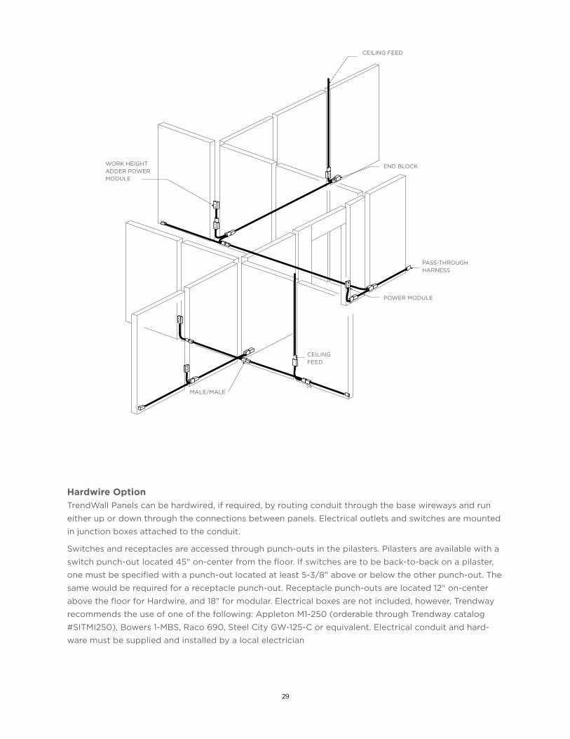
Hardwire Option TrendWall Panels can be hardwired, if required, by routing conduit through the base wireways and run
either up or down through the connections between panels. Electrical outlets and switches are mounted
in junction boxes attached to the conduit.
Switches and receptacles are accessed through punch-outs in the pilasters. Pilasters are available with a
switch punch-out located 45" on-center from the floor. If switches are to be back-to-back on a pilaster,
one must be specified with a punch-out located at least 5-3/8" above or below the other punch-out. The
same would be required for a receptacle punch-out. Receptacle punch-outs are located 12" on-center
above the floor for Hardwire, and 18" for modular. Electrical boxes are not included, however, Trendway
recommends the use of one of the following: Appleton M1-250 (orderable through Trendway catalog
#SITMI250), Bowers 1-MBS, Raco 690, Steel City GW-125-C or equivalent. Electrical conduit and hard-
ware must be supplied and installed by a local electrician
•
•
•
•
•
•
•
PASS-THROUGHHARNESS
CEILINGFEED
END BLOCK
MALE/MALE
POWER MODULE
WORK HEIGHTADDER POWER MODULE
14"
CEILING FEED

30
Acoustics 101 | The basics.
• You need to strike a balance between how much sound and how much silence is right for your space.
• Acoustics are described in several ways:
- Noise Reduction Coefficient (NRC), a single-number rating used in specification and product descriptions to show the sound-absorbing capabilities of a particular material. A material is classified as a sound absorber if it has an NRC value of at least 0.40. Porous materials, like fiberglass batt, have high NRC ratings.
- Sound Transmission Class (STC ), a single number system used to rate the airborne sound transmission performance of a product like a wall, panel or ceiling. The higher the STC number, the better the product’s ability to block sound transmission. Specifiers should not assume that a panel or partition with a higher STC rating is functionally better than one with a slightly lower rating, because a two- or three-point difference in STC ratings is not detectable by the human ear.
- Noise Criteria (NC) is the measurement of background noise in specific interior environments. Because too much quiet can be as distracting as too much noise, the ideal work environment provides a healthy balance between the two.
Typical Background Noise LevelsBoardroom NC -30
Auditorium NC -30
Video/conference room NC -30
Typical conference room NC -30
Private office NC -35-38
Open plan office NC -38-40
Public areas NC -40-55
- Speech Privacy Potential (SPP) is the measurement of how much privacy can be achieved from one area to another. SPP is calculated by adding together the STC and NC ratings. As shown in the chart below, an SPP less than 60 provides no privacy, while an SPP of 85 provides maximum privacy.
Privacy Rating SPP Description Potential
Total privacy 85 Shouting is barely audible.
Highly confidential 80 Normal levels not audible. Raised voices barely audible but not intelligible.
Excellent 75 Normal voice levels barely audible. Raised voices audible but mostly unintelligible.
Good 70 Normal voices are audible but unintelligible most of the time. Raised voices are mostly unintelligible.
Fair 65 Normal voices audible and intelligible some of the time. Raised voices are intelligible.
Acoustics

31
ACOUSTIC PERFORMANCE AND TRENDWALL | TrendWall has the capacity to provide acoustic privacy as good as or surpassing drywall.
TrendWall Speech Privacy Performance
Adjoining Area STC* NC SPP Privacy
Public Areas 42 40-45 80-85 Total Privacy
Open Plan Offices 42 38-40 78-80 Highly Confidential
Private Offices 42 35-38 75-78 Excellent
* Assumes TrendWall sound packing option
Office Partition Construction and Performance Levels
Other Construction Method STC
Drywall partition up to acoustical ceiling line STC -30
Drywall partition through acoustical ceiling 6" STC -35
Drywall partition with insulation, full height up to slab STC -40-45
Multiple layered drywall with insulation, full height up to slab STC -45+
Tips for maximum audio privacy with TrendWall:
• If glazing is required, specify Laminated Glass.
• Rectangular spaces diffuse sound better than square ones.
• Select Swing Doors vs Sliding Doors.
• For peak privacy, TrendWall should be paired with acoustical ceiling tiles that have a minimum CAC or CSTC rating of 40 and a minimum NRC rating of .65.
• Batt insulation can also be inserted above the ceiling tiles over a TrendWall office.
32
Note: Detailed, illustrated Installation Instructions and a training video are available on Trendealer:
Installation Training Video
INS138 TrendWall Floor-to-Ceiling Panels
INS172 TrendWall Electrical
INS495 TrendWall Skin Replacement Panel Disassembly
INS400 TrendWall Sliding Door
INS378 TrendWall Sound Packing
Installation
CORPORATE | Holland, Michigan | 800.968.5344 | Trendway.com
ATLANTA | CHICAGO | INDIANAPOLIS | LOS ANGELES | WASHINGTON, DC
5.12.2017