TravelMate 6293 Series Product End-of-Life Disassembly · PDF fileTravelMate 6293 Series...
21
TravelMate 6293 Series Product End-of-Life Disassembly Guide
Transcript of TravelMate 6293 Series Product End-of-Life Disassembly · PDF fileTravelMate 6293 Series...

TravelMate 6293 Series Product End-of-Life Disassembly Guide
Sylvia wang
矩形
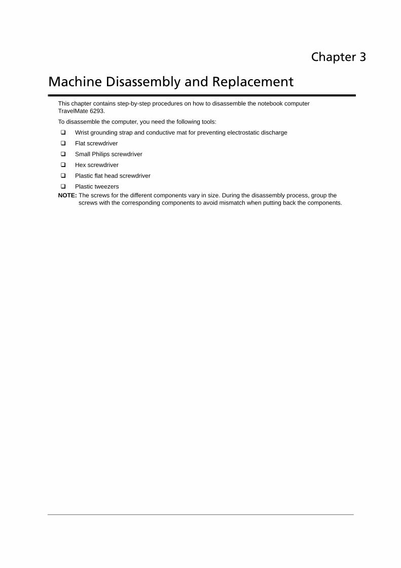
This chapter contains step-by-step procedures on how to disassemble the notebook computer TravelMate 6293.
To disassemble the computer, you need the following tools:
Wrist grounding strap and conductive mat for preventing electrostatic discharge
Flat screwdriver
Small Philips screwdriver
Hex screwdriver
Plastic flat head screwdriver
Plastic tweezersNOTE: The screws for the different components vary in size. During the disassembly process, group the
screws with the corresponding components to avoid mismatch when putting back the components.
Chapter 3
Machine Disassembly and Replacement
Sylvia wang
矩形

General Information
Before You BeginBefore proceeding with the disassembly procedures, make sure that you do the following:
1. Turn off the power to the system and all peripherals.
2. Unplug the AC adapter and all power and signal cables from the system.
3. Remove the battery pack.
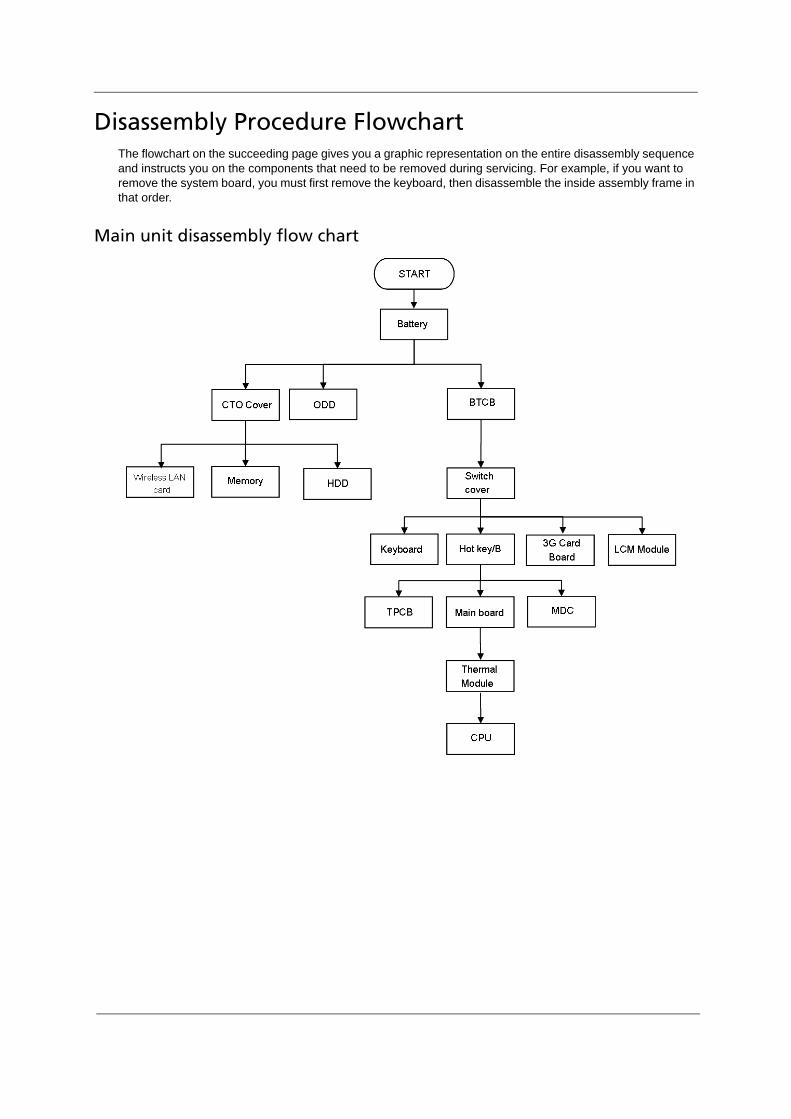
Disassembly Procedure FlowchartThe flowchart on the succeeding page gives you a graphic representation on the entire disassembly sequence and instructs you on the components that need to be removed during servicing. For example, if you want to remove the system board, you must first remove the keyboard, then disassemble the inside assembly frame in that order.
Main unit disassembly flow chart

LCM module disassembly flow chart

Removing the Battery Pack1. Release the battery.
2. Slide the battery latch then remove the battery.
Sylvia wang
印章
Sylvia wang
文字方塊
NOTE: Battery has been highlighted with the red circle as above image shows. Please detach the battery and follow local regulations for disposal.
Sylvia wang
橢圓形

Removing the HDD/Wirless Card/RAM Module/ODD/Express Dummy Card/Card Reader Dummy Module
Removing CTO Cover1. Loosen the 6 CTO cover screws.
2. Remove CTO cover.
Removing the HDD3. Remove HDD module.
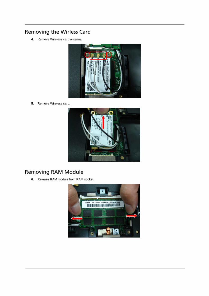
Removing the Wirless Card4. Remove Wireless card antenna.
5. Remove Wireless card.
Removing RAM Module 6. Release RAM module from RAM socket.

7. Remove RAM module.
Removing BTCB Screws8. Loosen and remove the BTCB screws X 16.
Removing ODD, Express Dummy Card, Dummy Card Reader9. Remove ODD module.

10. Press express card latch and remove express dummy card.
11. Push dummy card reader and remove the dummy card.
Remove Switch Cover 12. Pull Switch cover up.

13. Reverse Switch cover.
14. Disconnect Power/B FFC from the Switch cover.
Remove Keyboard 15. Pull Keyboard up.

16. Reverse Keyboard.
17. Disconnect K/B FFC from the MB.
Remove 3G SIM Card/B, Hotkey/B 18. Loosen 3G SIM card board screws X 2. Disconnect SIM card boardFFC.

19. Loosen Hotkey board screws X 2. Disconnect Hotkey board FFC.
Remove Wireless Antenna from TPCB 20. Remove Wireless antenna from the TPCB

Disconnect 3G wireless antenna cable21. Disconnect 3G module antenna.
Disconnect LCM cable, Touchpad FFC, BT cable 22. Disconnect LCM cable.

23. Disconnect Touchpad FFC.
24. Disconnect BT cable.

Disassemble LCM screws25. Loosen LCM screws X 4.
26. Remove LCM module
Disassemble TPCB27. Loosen TPCB screws X 3.

28. Remove TPCB.
Disconnect Modem cable, Wireless card cable, Speaker cable29. Disconnect Modem cable.
30. Disconnect Wireless cable.
31. Disconnect Speaker cable.

Remove Main board32. Remove M/B from the BTCB.
Sylvia wang
文字方塊
NOTE: Circuit boards >10 cm² has been highlighted with the red rectangle as above image shows. Please detach the Circuit boards and follow local regulations for disposal.
Sylvia wang
印章
Sylvia wang
矩形

Disassembly LCM module
Remove LCM bezel3. Remove six LCM bezel mylar.
4. Remove LCM bezel.
Remove Inverter board5. Disconnect Inverter cables.
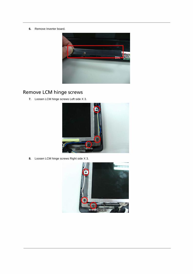
6. Remove Inverter board.
Remove LCM hinge screws7. Loosen LCM hinge screws Left side X 3.
8. Loosen LCM hinge screws Right side X 3.

Remove CCD cable9. Disconnect CCD cable.
Remove LCD panel10. Remove LCD panel from the TPDL.