Travel Trekker 40™, 40 Gallon, In-Bed Auxiliary Fuel ... · 4 Install the Grounding Wire Assembly...
17
TITAN Travel Trekker 40™ Installation Instructions, pt. no. 99 0000 0857 Page: 1 FOR DIESEL FUEL ONLY TITAN pt. no.: 99 0000 0857 Important: Please read these instructions carefully and completely before starting the installation. TITAN Fuel Tanks™ INSTALLATION INSTRUCTIONS Travel Trekker 40™, 40 Gallon, In-Bed Auxiliary Fuel System* Model 5410040 Congratulations! You have purchased the finest compact, in-bed auxiliary fuel system on the market. It has been designed to be attractive, durable and simple to install. It is baffled to minimize fuel sloshing and its compact dimensions allow it to be installed in most full-sized pickup truck beds without interfering with most hitches and conventional tonneau covers. It will also fit RAM trucks equipped with a RamBox® as well as midsized trucks such as the Chevrolet Colorado. With one touch, fuel transfers from the Travel Trekker™ to the vehicle’s primary fuel tank and continues to flow until it is automatically stopped by the controller or the button is touched again. The electronic controller indicates the fuel level in the auxiliary system at all times. The durability of TITAN’s fine military grade, cross-linked polymer tank products is legendary. We routinely test our tanks using state-of-the-art computer simulations as well as actual drop tests. We fill our tanks completely and drop them 30 feet onto a steel plate--never losing a drop of liquid. There are no welds to fail. If you ever accidentally run your gooseneck hitch into your Travel Trekker™ you will most likely find it springs right back. Soap and water and a little bit of Pledge® furniture spray, or Armor All® Protectant will keep your tank looking brand new. Pledge® is a registered trademark of S.C. Johnson & Son, Inc Armor All® is a registered trademark of Spectrum Brands. RamBox® and RAM are registered trademarks of FCA US LLC. * U.S. Patent No. 9174528 Travel Trekker 40™ Meets DOT FMCSA Title 49 Requirements
Transcript of Travel Trekker 40™, 40 Gallon, In-Bed Auxiliary Fuel ... · 4 Install the Grounding Wire Assembly...

TITAN Travel Trekker 40™ Installation Instructions, pt. no. 99 0000 0857 Page: 1
FOR DIESEL FUEL ONLY TITAN pt. no.: 99 0000 0857
Important: Please read these instructions carefully and completely before starting the installation.
TITAN Fuel Tanks™
INSTALLATION INSTRUCTIONS
Travel Trekker 40™, 40 Gallon, In-Bed
Auxiliary Fuel System* Model 5410040
Congratulations! You have purchased the finest compact, in-bed auxiliary fuel system on the market. It has been designed to be attractive, durable and simple to install. It is baffled to minimize fuel sloshing and its compact dimensions allow it to be installed in most full-sized pickup truck beds without interfering with most hitches and conventional tonneau covers. It will also fit RAM trucks equipped with a RamBox® as well as midsized trucks such as the Chevrolet Colorado. With one touch, fuel transfers from the Travel Trekker™ to the vehicle’s primary fuel tank and continues to flow until it is automatically stopped by the controller or the button is touched again. The electronic controller indicates the fuel level in the auxiliary system at all times. The durability of TITAN’s fine military grade, cross-linked polymer tank products is legendary. We routinely test our tanks using state-of-the-art computer simulations as well as actual drop tests. We fill our tanks completely and drop them 30 feet onto a steel plate--never losing a drop of liquid. There are no welds to fail. If you ever accidentally run your gooseneck hitch into your Travel Trekker™ you will most likely find it springs right back. Soap and water and a little bit of Pledge® furniture spray, or Armor All® Protectant will keep your tank looking brand new. Pledge® is a registered trademark of S.C. Johnson & Son, Inc Armor All® is a registered trademark of Spectrum Brands. RamBox® and RAM are registered trademarks of FCA US LLC. * U.S. Patent No. 9174528 Travel Trekker 40™ Meets DOT FMCSA Title 49 Requirements

TITAN Travel Trekker 40™ Installation Instructions, pt. no. 99 0000 0857 Page: 2
Fill Neck Throat = 1 3/8” diameter, to fit standard dispensing nozzles. Required Tools: Recommended Optional Tools: 1 ea. Power drill, electric or air powered 1 ea. Center Punch 1 ea. 7/16” Drill Bit 1 ea. Vehicle Hoist 1 ea. ¾” Drill Bit 1 ea. ½” Drill Bit 1 ea. Medium Phillips Screw Driver 1 ea. 9/16” End Wrench 1 ea. Ratcheting socket driver 1 ea. 9/16” Socket 1 ea. Tape Measure 1 ea. Torque Wrench 1 ea. Wire Stripper 1 ea. Wire Connection Crimper 1 ea. Small Propane Torch or Cigarette Lighter

TITAN Travel Trekker 40™ Installation Instructions, pt. no. 99 0000 0857 Page: 3
Exploded view showing the tank assembly of the Model 5410040.
Item Number Part Description
Part Number Quantity
1 Travel Trekker 40 Tank Body 99 0000 0820 1 2 Mounting Bracket 99 0000 0830 2 3 Toe Clamp 99 0000 0740 2 4 Sending Unit Cover 99 0000 0829 1
5 10-24 X 1/2" Button Head Socket Cap Screw, Black Oxide Stainless Steel 99 0000 0748 3
6 #10 Screw Size Flat Washer, Black Oxide Stainless Steel 99 0000 0749 3 7 Electronic Level Sensor 99 0000 0750 1 8 Roll Over Valve 99 0000 0137 1 9 Roll Over Valve with Vent Cap 99 0102 0000 1
10 Withdraw Tube Assembly 99 0000 0745 1 11 Black, Non-Locking Fuel Cap 99 0000 0534 1 12 In-Line Pump with Hose Barbs 99 0000 0521 1

TITAN Travel Trekker 40™ Installation Instructions, pt. no. 99 0000 0857 Page: 4
13 In-Line-Filter 99 0000 0405 1 14 3/8" Fuel Hose, 2" Length 99 0000 0858 2 15 #4 Hose Clamp 99 0000 0483 8 16 1/4"-20 X 5/8" Hex Drive Screw, Stainless Steel 99 0000 0853 2 17 1/4" Rubber Washer 99 0000 0854 2 18 Double Sided Tape 99 0000 0859 1 19 3/8"-16 X 1-1/2" Carriage Bolt 99 0000 0587 8 20 3/8"-16 X 1" Carriage Bolt 99 0000 0751 2 21 3/8" Push Nut Retainer 02 0000 0162 10 22 3/8" SAE Flat Washer 99 0000 0682 2 23 3/8"-16 Nylon Locknut 98 0000 0114 10 24 3/8" Oversized Flat Washer, 1-1/2" OD 99 0000 0588 8
N/A Grounding Wire 99 0173 0000 1 N/A 6-32 Machine Screw, 3/16" Length, Stainless Steel 99 0000 0756 1 N/A Electronic Controller 99 0130 0000 1 N/A 3/8" Fuel Hose, 6 Feet Length 99 0000 0759 1 N/A 5/16" Fuel Hose, 6 Feet Length 99 0000 0760 1 N/A Vent Line Filler Neck Adapter 99 0000 0409 1 N/A #8 Hose Clamp 99 0000 0422 2 N/A Push in Grommet 99 0000 0167 2 N/A Adhesive Backed Velcro, 2 Inch Length 99 0000 0283 1 N/A 18 AWG Black Wire, 20 Feet 99 0000 0761 2 N/A 18 AWG Purple Wire, 20 Feet 99 0000 0201 1 N/A 18 AWG Blue Wire, 20 Feet 99 0000 0482 1 N/A 18 AWG Crimp Insulated Ring Terminal, 3/8" Stud 99 0000 0204 3 N/A 18 AWG Heat Shrink Butt Splice Terminal 99 0000 0203 6 N/A 22-18 Gauge Barrel Quick-Disconnect Terminal 99 0000 0489 1 N/A ATM Fuse Tap 99 0000 0487 1 N/A Wire Loom, 6 Feet 99 0000 0762 1 N/A Mounting Template 99 0000 0848 1
Important Note for Vehicles with Aluminum Bodies
Some manufacturers of the new aluminum body pickup trucks recommend that no steel components be attached directly to the body. While TITAN’s in-bed products are made of military grade polymer, the mounting brackets are steel. If you contemplate installing your Travel Trekker 40™ in a vehicle with an aluminum body / bed, contact TITAN’s Customer Service first at 800.728.4982.

TITAN Travel Trekker 40™ Installation Instructions, pt. no. 99 0000 0857 Page: 5
Tank Body Installation I. Drill Mounting Holes Step Description 1 Following the diagram in Fig. 3, or using the included mounting template
(99 0000 0848), measure and mark hole centers on mounting surface (See Fig. 4). Before drilling, check under the bottom of the bed to make sure there are no cross members on the bed that will interfere with installation. If there is a conflict, move the “footprint” of the tank slightly forward or back to clear the obstruction.
2 Drill eight mounting holes using a 3/8” drill bit. Next, unless you intend to use a pre-made, plugged hole, if your vehicle is so equipped (See Fig. 2), you will also need to drill three holes on the driver’s side near the front of the bed. Two (3/4”) will be required for the fuel hoses (supply and return lines) and one (1/2”) for the wire loom to pass through (See Fig. 1). Install rubber grommets in the ¾” holes for the two fuel lines (See Fig. 10). NOTE: When assembling any of this product’s threaded NPT connections, be sure to use a thread sealing tape or thread sealing compound. Be sure the tape or compound is compatible with motor fuels including biodiesel.
(Fig. 1) Holes for fuel lines and wire loom to pass. (Fig. 2) Fuel lines and wire loom can pass through plugged Grommets shown installed in fuel line openings. holes on vehicles so equipped.

TITAN Travel Trekker 40™ Installation Instructions, pt. no. 99 0000 0857 Page: 6
(Fig. 3) Mounting bracket bolt hole pattern for 40 Gallon, Travel Trekker, Model 5410040.

TITAN Travel Trekker 40™ Installation Instructions, pt. no. 99 0000 0857 Page: 7
(Fig. 4) Template for drilling mounting holes taped down. (Fig. 5) Assemble the Mounting Bracket’s fasteners as shown here.
(Fig. 6) Use a deep socket to install Push Nut Retainer (Fig. 7) Install “99 0173 0000 Ground Wire on 3/8”carriage bolts as shown. Assembly” on front bolt in the “99 0000 0830 Mounting Bracket” which is to be installed on the driver’s side of the vehicle.
II. Install Mounting Brackets 3 Assemble the two Mounting Brackets (99 0000 0830) with push nuts and carriage bolts as shown in Figs. 5 & 6.

TITAN Travel Trekker 40™ Installation Instructions, pt. no. 99 0000 0857 Page: 8
4 Install the Grounding Wire Assembly on the front inside bolt of the driver’s side (left hand) Mounting Bracket as shown in Figs. 7 & 8. 5 Install the two Mounting Brackets in the bed of the vehicle and install washers and nylon locknuts, finger tight, on the exposed bracket bolts underneath the bed.
(Fig. 8) Driver’s side Mounting Bracket installed. (Fig. 9) Showing grounding wire attached to the Electronic Note the ground wire attached to front inside Level Sensor. bolt. The other end attaches to the Electronic Level Sensor on the tank.
(Fig. 10) Install rubber grommet into fuel line hole(s). (Fig. 11) Toe clamps installed on Mounting Brackets
III. Set Tank in Brackets 6 Place the tank body into the Mounting Brackets front clamps. 7 Install the two Toe Clamps (99 0000 0740) onto the brackets at the rear side of the tank. The Toe Clamps are slotted so as to be adjustable. Place them snugly against the tank and tighten the Toe Clamp bolts to 25 lb. ft. (See Fig. 11). 8 Tighten locknuts underneath the bed to 25 lb. ft.

TITAN Travel Trekker 40™ Installation Instructions, pt. no. 99 0000 0857 Page: 9
IV. Installation of Fuel Transfer Tie-In to Vehicle’s Fuel Tank 9 See “plumbing diagram below (Fig. 12), and wiring diagram (Fig. 15):
(Fig. 12) Plumbing Diagram for Model 5410040 Travel Trekker™, 40 gallon with TITAN™ Electronic Controller and pump system.
TITAN Travel Trekker 40™ Installation Instructions, pt. no. 99 0000 0857 Page: 10
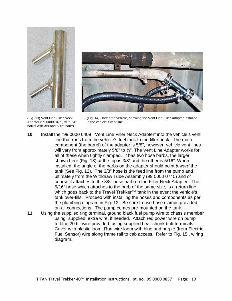
(Fig. 13) Vent Line Filler Neck (Fig. 14) Under the vehicle, showing the Vent Line Filler Adapter installed Adapter (99 0000 0409) with 5/8” in the vehicle’s vent line. barrel with 3/8”and 5/16” barbs. 10 Install the “99 0000 0409 Vent Line Filler Neck Adapter” into the vehicle’s vent line that runs from the vehicle’s fuel tank to the filler neck. The main component (the barrel) of the adapter is 5/8”, however, vehicle vent lines will vary from approximately 5/8” to ¾”. The Vent Line Adapter works for all of these when tightly clamped. It has two hose barbs, the larger, shown here (Fig. 13) at the top is 3/8” and the other is 5/16”. When installed, the angle of the barbs on the adapter should point toward the tank (See Fig. 12). The 3/8” hose is the feed line from the pump and ultimately from the Withdraw Tube Assembly (99 0000 0745) and of course it attaches to the 3/8” hose barb on the Filler Neck Adapter. The 5/16” hose which attaches to the barb of the same size, is a return line which goes back to the Travel Trekker™ tank in the event the vehicle’s tank over-fills. Proceed with installing the hoses and components as per the plumbing diagram in Fig. 12. Be sure to use hose clamps provided on all connections. The pump comes pre-mounted on the tank. 11 Using the supplied ring terminal, ground black fuel pump wire to chassis member using supplied, extra wire, if needed. Attach red power wire on pump to blue 20 ft. wire provided, using supplied heat-shrink butt terminals. Cover with plastic loom. Run wire loom with blue and purple (from Electric Fuel Sensor) wire along frame rail to cab access. Refer to Fig. 15 , wiring diagram.

TITAN Travel Trekker 40™ Installation Instructions, pt. no. 99 0000 0857 Page: 11
(Fig. 15) TITAN™ Electronic Controller, pump, and sensor wiring diagram.

TITAN Travel Trekker 40™ Installation Instructions, pt. no. 99 0000 0857 Page: 12
(Fig. 16) Using the supplied fuse tap, connect power (Fig. 17) Showing completed plumbing and wiring Input wire to output side of 10-15 Amp fuse (Max on tank body. Tape backing is being removed in 15 Amp). preparation for installation of the cover. 12 Complete the wiring as per wiring diagram (Fig. 15) and install fuse tap on output side of a 10-15 Amp fuse (Fig. 16) in the vehicle’s fuse panel. Be sure to place the provided plastic wire loom on the system’s wiring for extra protection. Please notice that the TITAN Controller only requires a power tap and the grounding point on the battery terminal; there is no invasion into the vehicle’s wiring at any point. 13 Install the TITAN™ Controller in the vehicle’s cab by drilling a hole at the chosen mounting point, threading the wire through, and using the Velcro tape to hold the controller firmly (Fig. 18).
(Fig. 18) TITAN™ Electronic Controller mounted on dash.
VI. Fill and Final Check 14 Make a complete careful check of all components to be sure that all bolts,
clamps, caps, accessories and misc. are tight and secure. 15 IMPORTANT: Fill tank completely with fuel and inspect all components

TITAN Travel Trekker 40™ Installation Instructions, pt. no. 99 0000 0857 Page: 13
carefully to be sure that there are no leaks or other problems. Check the operation of any valves, pumps or control systems. 16 Study Fig. 19 below for instructions on operating the TITAN™ Controller.
(Fig. 19) Operating instructions for TITAN™ Electronic Fuel Controller.

TITAN Travel Trekker 40™ Installation Instructions, pt. no. 99 0000 0857 Page: 14
Troubleshooting Guide
Consistently, the biggest problem we see causing system malfunctions is a poor or uncertain ground or a bad connection. A poor ground will cause the electronic controller, pump, and other components not to function or to perform intermittently. Below you will find a troubleshooting guide to help if you are experiencing system problems. Controller does not light: 1) Check for power on the red wire to the controller. If you have no power, check the connections and the fuse providing power from the vehicle’s electrical system. 2) Check the connections on the ground which is the black wire from the controller. Make sure the level sensor and the electronic controller are grounded to a common grounding point on the negative terminal of the battery (see Fig. 15) Controller lights, but the level indicator bars do not: 1) Make sure there is sufficient fuel in the tank. The indicator bars and the pump will not function if the level sensor reads “empty”. 2) Check connections on the level sensor circuit. This is a purple wire leading from the controller which connects to the pink wire on the level sensor. The level sensor’s black wire and the controller’s black ground wire must be securely grounded at the same, common point to the negative battery terminal (see Fig. 15). Pump runs slow: Check the ground (black wire) on the pump itself. Pump makes noise, but doesn’t transfer fuel: Inspect feed line (3/8 line from tank to filter/pump assembly, then also pump to primary tank) for kinks or a plugged fuel filter. Pump does not run: Check the pump and controller grounds. Also, assure there is 12 volts to the pump when activated (on blue wire from the controller). Controller flashes and does not light the red “transfer” light in the upper right corner: This is a sign of excess system resistance. Step 1) Check the grounds on both the controller (Fig. 15) and the pump. Step 2) Inspect the fuel feed line that goes to the pump to assure it is not kinked that the fuel filter is not clogged. Step 3) Inspect the blue wire from the controller to the pump and the wiring to the level sensor (the purple wire from the controller) for damage such as being pinched, a fault in the insulation, etc. Check the ground on the level sensor (black wire) to be sure it is adequate. The level sensor is basically a resistor with a maximum of 240 ohm when the tank is empty, and 33 ohm when the tank is full. If the level sensor is outside of that specification (caused by inadequate ground or a damaged or faulty wire) it will put the entire system out of specification. Once again, a good ground is mandatory for each component in this system. A poor ground will add unnecessary resistance and cause feedback from one component to another. Added resistance causes the controller to reset as a failsafe. ©2017 TITAN Fuel Tanks, All rights reserved. 5.25.17

TITAN Travel Trekker 40™ Installation Instructions, pt. no. 99 0000 0857 Page: 15
Important Note for Chrysler RAM Vehicles
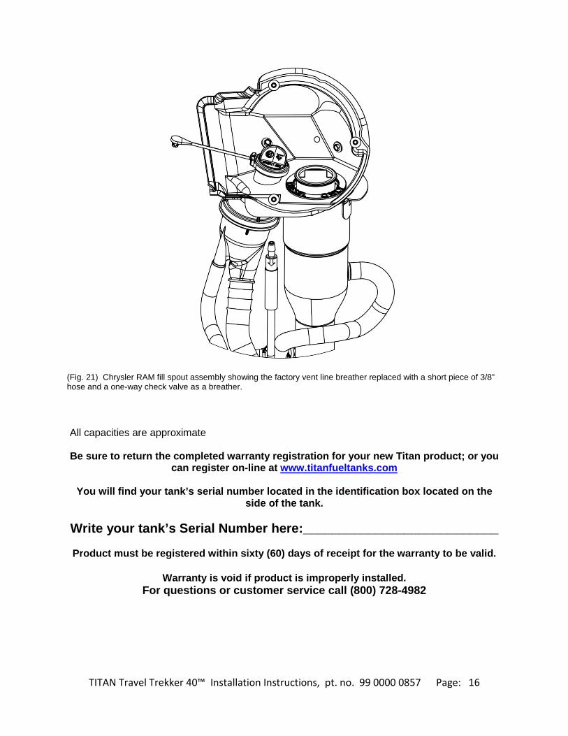
Some 2013 and newer Chrysler RAM products feature a vent line breather which is usually located in the fender well just under the vehicle’s fill spout assembly (See Fig. 20). On some of these vehicles, especially the EcoDiesel, this breather is susceptible to leakage which can be exacerbated by filling from an auxiliary system. If this is a problem for your vehicle, it can be addressed in one of two ways: 1) Since the vehicle’s OEM underbody tank is now also vented through the Travel Trekker™, the vent line can be trimmed and plugged as discussed in Fig. 20. or 2) Trim the vent line where shown in Fig. 20 and add a short piece of hose and a one way check valve as a breather as shown in Fig. 21. Ask your TITAN dealer for “9900002 One-Way Breather Kit for Chrysler Vehicles”.
(Fig. 20) Fill spout assembly on some Chrysler RAM products. The vent line breather is shown just above the point of the arrow. Since the vehicle’s underbody tank is now also vented through the Travel Trekker™, the vent line can be cut where indicated on the illustration. Then, slip on a short piece of 3/8” hose over the vent line and plug with a plastic plug, or small cap screw, etc. Be sure to use hose clamps to insure a leak-proof seal.
TITAN Travel Trekker 40™ Installation Instructions, pt. no. 99 0000 0857 Page: 16
(Fig. 21) Chrysler RAM fill spout assembly showing the factory vent line breather replaced with a short piece of 3/8” hose and a one-way check valve as a breather. All capacities are approximate Be sure to return the completed warranty registration for your new Titan product; or you
can register on-line at www.titanfueltanks.com
You will find your tank’s serial number located in the identification box located on the side of the tank.
Write your tank’s Serial Number here:___________________________
Product must be registered within sixty (60) days of receipt for the warranty to be valid.
Warranty is void if product is improperly installed.
For questions or customer service call (800) 728-4982

TITAN Travel Trekker 40™ Installation Instructions, pt. no. 99 0000 0857 Page: 17
TITAN™ Fuel Tanks P.O. Box 2225
Idaho Falls, ID 83403 USA Telephone (208) 522-1325, FAX (208) 529-2162
Toll Free: (800) 728-4982
www.titanfueltanks.com TITAN Fuel Tanks™ are PROUDLY MADE IN THE USA Revised 9.14.17 ©2017 TITAN Fuel Tanks, All rights reserved.