Trapping and manipulation of individual nanoparticles in a ...
TRAPPING AND MANIPULATION OF PARTICLES AND DROPLETS USING MICRO-TOROIDAL CONVECTION CURRENTS
Amar S. Basu*, and Yogesh B. Gianchandani Department of Electrical Engineering and Computer Science
University of Michigan, Ann Arbor, USA
* Address: 1301 Beal Avenue, Ann Arbor MI 48109-2122, USA; Tel: (734) 709-6688; Fax: (734) 647-1781; E-mail: [email protected]
ABSTRACT This paper introduces a technique for generating toroid-
shaped convective vortices in thin (80-400 µm) layers of oil. Driven by micromachined heat sources suspended 5-250 µm above the oil surface, the vortices are used to trap weed pollen with 25 µm diameter and microdroplets of water with diameters ranging from 2-50 µm. The speed of the convective flow pattern can be controlled by the input power to the heat source and the air gap between the heat source and the oil surface, while the radius of the collection region is determined primarily by the thickness of the oil layer. Flow velocities up to 1700 µm/sec have been achieved in toroidal flows with radii ranging from 80-1120 µm. When the heat source is connected to an XY scanning stage, the vortex can be swept across the liquid, effectively collecting particles in the areas over which it travels.
Keywords: Rayleigh-Benard convection cell, Benard-Marangoni convection, oil, microfluidic vortex, microdroplet, toroid, particle trap.
I. INTRODUCTION Oil is being increasingly used as a liquid phase in
biological and chemical analysis systems. Microdroplets of water emulsified in oil have been used as micro-scale chemical reactors in several applications including the concentration of dissolved solutes and nanoparticles [1] as well as the amplification of single DNA molecules [2]. The low evaporation rates of oil make it a desirable collection medium for long-term non-toxic sampling of airborne bioparticulates [3], and its optical transparency has made it popular as a liquid medium for micro-droplet based embryo culture [4].
Within the context of microfluidic systems, prior work has focused on how to generate microdroplets of water within a continous oil phase [5] and manipulate them (one at a time) using electrophoretic [6] or optical [7] forces. Little has been reported, however, on how to drive micro-scale currents in an oil phase. The viscosity of moist oils makes mechanical pumping difficult to implement, and its nonpolar nature excludes electrokinetic methods of flow manipulation. Toward this end, we present a method to generate steady state micro-scale currents within oil using thermal convection, and discuss how they can be used to collect and manipulate both microdroplets and immersed particles.
The convective flow patterns are driven by
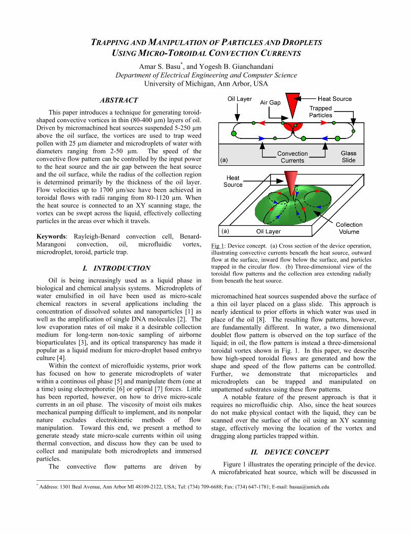
micromachined heat sources suspended above the surface of a thin oil layer placed on a glass slide. This approach is nearly identical to prior efforts in which water was used in place of the oil [8]. The resulting flow patterns, however, are fundamentally different. In water, a two dimensional doublet flow pattern is observed on the top surface of the liquid; in oil, the flow pattern is instead a three-dimensional toroidal vortex shown in Fig. 1. In this paper, we describe how high-speed toroidal flows are generated and how the shape and speed of the flow patterns can be controlled. Further, we demonstrate that microparticles and microdroplets can be trapped and manipulated on unpatterned substrates using these flow patterns.
A notable feature of the present approach is that it requires no microfluidic chip. Also, since the heat sources do not make physical contact with the liquid, they can be scanned over the surface of the oil using an XY scanning stage, effectively moving the location of the vortex and dragging along particles trapped within.
II. DEVICE CONCEPT Figure 1 illustrates the operating principle of the device.
A microfabricated heat source, which will be discussed in
Fig 1: Device concept. (a) Cross section of the device operation, illustrating convective currents beneath the heat source, outward flow at the surface, inward flow below the surface, and particles trapped in the circular flow. (b) Three-dimensional view of the toroidal flow patterns and the collection area extending radially from beneath the heat source.

further detail below, is suspended just above the surface of a thin layer of oil placed on a glass slide. When the separation between the heat source and the oil surface is sufficiently low (<400 µm), heat transferred through the thin air gap to a small region on the oil surface drives convection currents in a small region beneath the heat source (Fig. 1a). Within this volume, fluid flows vertically upwards, resulting in outward flow at the top surface of the fluid and inward flow below the surface. Together, the surface and subsurface currents form a circular vortex in which particles are trapped. Observed in three-dimensions, the flow pattern is a toroid centered below the heat source (Fig. 1b). The flow pattern is similar to a single Rayleigh-Bénard cell in which the convection rolls are radially oriented.
The physical effect driving the flow is likely a combination of buoyancy (Rayleigh-Bénard convection) as well as surface tension (Bénard-Marangoni convection). The elevated temperature beneath the probe decreases the density of the oil, resulting in buoyancy driven flow as the fluid in this region rises towards the surface. The local surface tension of the oil also decreases, resulting in Marangoni forces which drive outward flow on the top surface. Surface tension driven effects tend to dominate in thin layers of fluid [9-10].
The heat sources used in the experiments are microfabricated scanning thermal probes described in [11].
The devices consist of a gold thin film heater embedded at the tip of a polyimide cantilever. Electrical connection is provided by thicker metal lines running the length of the cantilever. Due to the low thermal conductivity of polyimide, the probes can be heated to 250°C with less than 20 mW input power. The probes are 120 µm in width, 360 µm in length, and have resistances ranging from 25-35 ohms.
III. EXPERIMENTAL RESULTS Controlled toroidal flows and trapping were
demonstrated in various oils including mineral oil (Rite Aid Pharmacy), olive oil (Philip Berio), and kerosene oil (Commonwealth Oil). For all experiments, a 250 µL sample of oil was spread on a glass microscope slide to achieve the desired thickness.
Figure 2 illustrates the path of a typical particle trapped within the flow. In this experiment, weed pollen (Sigma-Aldrich), with approximately 30 µm diameter, was immersed in mineral oil. Video images obtained using a CCD camera were analyzed frame by frame to determine the position of a selected particle at 1/30 second intervals.
The radial position of a typical particle was measured (Fig. 2a) for 4.7 seconds, corresponding to two full cycles. Qualitatively, it travels away from the heat source on the top
�
���
���
���
���
� � � � � ����� �
�����
���
� ����
���
� �������������� �
������������
��������
���� �����������
���
����
���
�
���
����
����
����
� ��� ��� ���
��������� ������� �
�����
��!��
"��#��
$
� �������������� �
��������������������
���� ����������
���
%&���&��
'���&��
Fig 2: Trajectory of a typical particle trapped in the toroidal convection currents generated with 18 mW input power to a heat source suspended 30 µm above the surface of 140 µm-thick mineral oil. (a) Radial displacement of the particle from the toroid center is graphed as a function of time for two cycles. (b) Particle velocity graphed as a function of the radial position for two cycles illustrates steady state flow.
���
�
���
����
����
����
� � �� �� ��
'��&����������
���
(��
)��
*�������
�������������� ��
���� ����������
��+�!
��
"��#��
$
����
�
���
����
����
����
� ��� ��� ��� ���
��+�!
��
"��#��
$
�
����)�������
�����
�������������� ��
���� ����������
*���,���� �
Fig 3: The speed of the toroidal flow pattern scales with the amount of heat transferred to the oil surface. (a) At a fixed separation between the heat source and the oil surface, the maximum particle velocity increases as a function of input power. (b) At a fixed input power, increasing the air gap decreases the flow velocity due to the reduced heat transferred to the surface. 140 µm mineral oil was used in all experiments.

surface of the oil, slowing gradually. Eventually, the particle reaches zero velocity at the outer edge of the collection region, at which point it sinks to the bottom of the oil layer and is accelerated inward. Upon reaching the center of the vortex beneath the heat source, the particle rises quickly to the surface and attains maximum lateral velocity as it is propelled outward.
The instantaneous radial velocity, calculated by taking the derivative of the displacement data, is shown in Fig. 2b as a function of radial position. The two cycles graphed overlap one another, showing that the fluid velocity field is steady state both spatially and temporally.
As expected with convection currents, flow velocities are determined primarily by the fluid temperature, which in turn can be controlled by the heat transferred to the oil surface. In the case of the scanning thermal probes, the degree of heat transfer is determined by two factors: 1) the temperature of the cantilever tip, which is proportional to the input power [11], and 2) the distance between the cantilever and the surface of the oil. Flow velocities were measured at various powers and air gaps, and it was found that velocities increase linearly with respect to input power, and decay exponentially as the probe is moved away from the liquid surface (Fig. 2.). Velocities also depend on the viscosity and thickness of the oil layer, and, to a lesser degree, the ambient temperature (data not shown).
While the speed can be tailored through the control of surface temperature, it was observed that for a given oil, the radius of the collection region is set by the thickness of the fluid layer. Figure 4 shows that the radius of the toroid scales as a power function of the oil layer thickness.
Several applications of toroidal flows are shown in Fig. 5. Trapping of weed pollen demonstrates the ability to collect an airborne particulate. To demonstrate the collection of microdroplets, 5 µL of water was pipetted into an oil sample and stirred vigorously to produce droplets with radii ranging from 5-100 µm. Small droplets tend to travel the entire convective flow path, whereas larger droplets travel smaller paths. To visualize flow patterns, microdroplets of Rhodamine dye were emulsified into the oil in the same manner. A one second CCD exposure picture illustrates the radially oriented flow paths.
�
���
(��
)��
����
� ��� ��� ��� ���
%����-�"+� �� �
����
����
���&
��
�
�������������� ����������������������
Fig 4: Radius of the toroidal flow pattern as a function of oil thickness. Input power and probe-oil separation are fixed at 18 mW and 100 µm, respectively. Mineral oil was used in this experiment.
Fig 5: Applications of the toroidal flow pattern in particle and droplet collection. (a) Schematic showing the heat source, XY scanning stage, toroidal flow patterns, and particles trapped within the collection area. Collection of (b) weed pollen in 125 µm mineral oil, and (c) microdroplets of water in 80 µm-thick olive oil, using an 18 mW heat source and an air gap of 75 µm and 200 µm, respectively, and (d) 1 second exposure fluorescent image illustrating the movement of water microdroplets containing fluorescent dye.

To be able to manipulate particles in a highly localized manner requires that the collection region have a small radius. A thin layer of oil would, therefore, be ideal. Thinning the oil layer, however, increases viscous effects which impede the ability of the top and bottom portions of the oil to move in opposite directions, resulting in decreased flow velocities and decreased trapping ability. Low viscosity kerosene oil was consequently chosen as the liquid medium to demonstrate localized particle collection in thin oil layers. In this experiment, a heat source mounted on an XY scanning stage produced a movable collection region with 50 µm radius (Fig. 6). As the heat source is scanned laterally, several weed pollen are swept up into the vortex and moved to a new location.
IV. CONCLUSIONS In conclusion, we have shown that point heat sources
can be used to generate micro-scale toroidal flows in which particles and microdroplets can be deliberately trapped. The speed of the flow pattern can be tuned using the heat source, while the radius is set by the thickness of the oil layer. This approach is unique in that it does not require a microfluidic chip. Futhermore, since the heat source does not make physical contact with the liquid, it allows the vortices to be scanned across the liquid surface.
ACKNOWLEDGEMENTS Partial support for this effort was provided by The
Whitaker Foundation (AB). The authors also acknowledge Dr. Shamus McNamara for his assistance in probe fabrication.
REFERENCES [1] M. He, C. Sun, and D.T. Chiu, “Concentrating Solutes and Nanoparticles within Individual Aqueous Microdroplets”, Anal. Chem., 76, pp. 1222-1227 (2004). [2] M. Nakano, J. Komatsu, S. Matsuura, K. Takashima, S. Katsura, and A. Mizunoo, “Single Molecule PCR using water-in-oil emulsion,” J. Biotech., 102, pp.117-24 (2003). [3] X. Lin, T.A. Reponen, K. Willeke, S.A. Grinshpun, K.K. Foarde, and D.S. Ensor, “Long-term sampling of airborne bacteria and fungi into a non-evaporating liquid,” Atmos. Env., 33, pp 4291-4298 (1999). [4] S. Lee, M. Cho, E. Kim, T. Kim, C. Lee, J. Han, and J. Lim, “Renovation of a Drop Embryo Cultures System by Using Refined Mineral oil and the Effect of Glucose and/or Hemoglobin Added to a Serum-free Medium,” J. Vet. Med. Sci., 66, pp. 63-66 (2004). [5] T. Thorsen, R.W. Roberts, F.H. Arnold, and S.R. Quake, “Dynamic Pattern Formation in a Vesicle-Generating Microfluidic Device”, Phys. Rev. Lett., 36, pp.4163-4166 (2001). [6] S. Katsura, A. Yamaguchi, N. Harada, K. Hirano, A. Mizuno, “Micro-reactors based on water-in-oil emulsion”, Proc. 1999 IEEE Industry Applications Conference, Phoenix, AZ, October 2004, pp. 1124-1129. [7] A. Ashkin, "Application of Laser Radiation Pressure", Science, 200, pp.1081-1087 (1980). [8] A.S. Basu, and Y. B. Gianchandani, “High Speed Microfluidic Doublet Flow In Open Pools Driven by Non-Contact Micromachined Thermal Sources”, Proc. Intl. Conf. on Micro Electro Mechanical Sys., Miami Beach, FL, February 2005, pp. 666-669. [9] J.R.A. Pearson, “On convection cells induced by surface tension”, J. Fluid Mech., 19, pp. 489-500 (1958). [10] K. Nitschke and A. Thess, “Secondary instability in surface-tension-driven Bénard convection”, Phys. Rev. Lett., 52, pp. 5772-5775 (1995). [11] M.H. Li and Y.B. Gianchandani, "Applications of a Low Contact Force Polyimide Shank Bolometer Probe for Chemical and Biological Diagnostics," Sens. Actuators A Phys, 104, pp. 236-245 (2003).
Fig 6: Collection of 25 µm weed pollen immersed in 80 µm-thick kerosene oil using an 18 mW heat source held 50 µm above the oil surface and scanned as indicated. (1) Heat source is advanced towards the particles. (2,3) When the heat source reaches the area above the particles, the particles are swept into the vortex and trapped. (4) The trapped particles are moved to a new location.