Transverse to Longitudinal Emittance Exchange Results · Transverse to Longitudinal Emittance...
19
BROOKHAVEN SCIENCE ASSOCIATES Transverse to Longitudinal Transverse to Longitudinal Emittance Emittance Exchange Results Exchange Results Ray Fliller III NSLS-II Project Brookhaven National Laboratory (formerly of Fermilab) and Tim Koeth Rutgers University and Fermilab (now at University of Maryland) For the Fermilab A0 Team ICFA Mini Workshop
Transcript of Transverse to Longitudinal Emittance Exchange Results · Transverse to Longitudinal Emittance...

BROOKHAVEN SCIENCE ASSOCIATES
Transverse to Longitudinal Transverse to Longitudinal EmittanceEmittance Exchange ResultsExchange Results
Ray Fliller IIINSLS-II Project
Brookhaven National Laboratory(formerly of Fermilab)
and Tim Koeth
Rutgers University and Fermilab(now at University of Maryland)
For the Fermilab A0 TeamICFA Mini Workshop

BROOKHAVEN SCIENCE ASSOCIATES
AcknowledgementsAcknowledgements
FermilabHelen EdwardsRay Fliller (now at BNL)Tim Koeth (now at University of Maryland)Jinhao RuanAmber JohnsonYin-e SunArtur PaytyanMike Davidsaver (now at BNL)Grigory Kazakevich (now at Omega-P Inc.)Manfred WendtRandy Thurman-KeupVic ScarpineAlex Lumpkin
Northern Illinois University•Philippe Piot

BROOKHAVEN SCIENCE ASSOCIATES
Transverse to Longitudinal Transverse to Longitudinal EmittanceEmittance Exchange Exchange –– How?How?
There have been two proposals for EEX in a linac1. Use a deflecting cavity in the middle of a chicane (Cornacchia and Emma, 2002)2. Use a deflecting cavity in the middle of two doglegs (Kim and Sessler, 2006)
1. Emma, et.al. in 2006 combined this scheme with a round to flat beam transformer as well.
Both FNAL and ANL use the Kim and Sessler scheme.Incoming beam is manipulated to have the appropriate transverse and longitudinal phase ellipsesFirst dogleg provides dispersion at DMC.The deflecting cavity gives a longitudinal position dependant transverse kick and a transverse position dependant momentum kick.The second dogleg couples the remaining correlations to finish the exchange.
final e- bunch
Initial e- bunch
εx < εz
D1
εx > εz
D2 D3
D4
3.9 GHz TM110

BROOKHAVEN SCIENCE ASSOCIATES
How does the exchange work??How does the exchange work??The transverse – longitudinal transport matrix R, and beam matrix σ look like (in 2x2 block mode)
The beam matrix after the transport is given by
If the R matrix can be made to look like
Then the beam matrix looks like
TRR 12 σσ =
⎟⎟⎠
⎞⎜⎜⎝
⎛=
z
x
σσ
σ0
01⎟⎟
⎠
⎞⎜⎜⎝
⎛=
DCBA
R
⎟⎟⎠
⎞⎜⎜⎝
⎛=
00C
BR
⎟⎟⎠
⎞⎜⎜⎝
⎛= T
x
Tz
CCBB
σσ
σ0
02
New Longitudinal Emittance is the old Horizontal emittance
New Horizontal Emittance is the old longitudinal emittance

BROOKHAVEN SCIENCE ASSOCIATES
How does the exchange work??How does the exchange work??Assume that the beamline consists of a before cavity section, a DMC, and an after cavity section.
Assume that the before cavity section produces some dispersion, η, with a slope η’.Assume that the cavity is a zero length element
What does the cavity strength need to be?
What are the needed properties for the after cavity section?
These equations come out of nothing more than the symplectic condition and the condition that the A and D blocks of the R matrix are all zeros.Note: The vertical emittance is unaffected by the transformation.
⎟⎟⎠
⎞⎜⎜⎝
⎛⎟⎟⎠
⎞⎜⎜⎝
⎛=⎟⎟
⎠
⎞⎜⎜⎝
⎛'2221
1211
26
16
ηη
acac
acac
ac
ac
MMMM
MM
bccavac MMMR =
FNAL Beams Doc 2553
ηω 10 −==
EceVk
BROOKHAVEN SCIENCE ASSOCIATES
FlyFly’’s in the Ointments in the OintmentThere are many effects that may leave residual coupling, dilute, or obscure the emittance exchange.
Linear Flies – can lead to residual coupling of the emittances, leading to an emittance increase
• I’ve assumed an infinitely thin cavity, a finite length cavity will leave residual coupling
• Building an imperfect beamline such as using a chicane vs. a double dogleg as Cornacchia and Emma pointed out.
• Incorrect cavity strength – too strong is as bad as too weak.These can be minimized or eliminated by manipulating the
incoming beam phase spaces Ugly Flies – these can blow up the emittances, possibly washing out the effect of the exchange
• Space charge• Coherent Synchrotron RadiationThese can be minimized by lowering the beam
charge.

BROOKHAVEN SCIENCE ASSOCIATES
Watching the Exchange Watching the Exchange –– The Fermilab experimentThe Fermilab experiment
Before Dipole 2Before DMCAfter DMC
Before Dipole 4Exchange Complete
Input to the EEX line

BROOKHAVEN SCIENCE ASSOCIATES
A0 PhotoinjectorA0 Photoinjector
L band 1.5 cell NC RF gun with Cs2Te photocathode35 MV/m maximum cathode gradient
TESLA technology accelerating cavity12 MV/m accelerating gradient
Round to Flat beam transformerTransverse to Longitudinal Emittance Exchange BeamlineQuadrupole transport channelUser experimental area
BROOKHAVEN SCIENCE ASSOCIATES
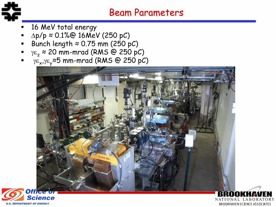
Beam ParametersBeam Parameters16 MeV total energyΔp/p ≈ 0.1%@ 16MeV (250 pC)Bunch length ≈ 0.75 mm (250 pC)γεz ≈ 20 mm-mrad (RMS @ 250 pC)γεx,γεy≈5 mm-mrad (RMS @ 250 pC)

BROOKHAVEN SCIENCE ASSOCIATES
Preliminary investigations showed encouraging results. For instance, as we increased the TM110 cavity strength we saw a reduction in momentum spread…
Early EEX Signature from SpectrometerEarly EEX Signature from Spectrometer
Cavity: OFFCavity 10%Cavity 20%Cavity 30%Cavity 40%Cavity 50%Cavity 60%Cavity 70%Cavity 80%Cavity 100%Spectrometer Screen
~ 550keV

BROOKHAVEN SCIENCE ASSOCIATES
k=0 %kideal
Measuring the RMeasuring the R1414 and Rand R3434 through the EEX linethrough the EEX line
k=25 %kidealk=50 %kidealk=75 %kideal
Lines: ModelDots : Horizontal BPM measured difference data
δP = ± 1.05 % in 0.35 % increments
Evolution of the beam trajectory as the cavity strength is increased, and energy is changed
Hor
izon
tal B
PM D
iffe
renc
e (m
m)
Vert
ical
BPM
Dif
fere
nce
(mm
)
k=90 %kideal Momentum deviation removed,
Converted into positions and angles!

BROOKHAVEN SCIENCE ASSOCIATES
Measured EEX Transport Matrix Measured EEX Transport Matrix
INOUTEEX transport matrix as a function of deflecting cavity strength
X
X’
Z
δ
=
X
X’
Z
δ
Circles are measurements, green lines are a weighted linear fitRed lines are calculated expected values
Measured full 6 x 6; the vertical plane is unaffected by the cavity status…
FR5PFP020

BROOKHAVEN SCIENCE ASSOCIATES
Emittance Exchange Data Sets from A0 Emittance Exchange Data Sets from A0 –– PRELIMINARY!!!PRELIMINARY!!!
Plane ε[mm-mrad] input ε[mm-mrad] output
Horizontal 4.7 20Vertical 5.1 6.0
Longitudinal 21 7.0
Successful exchange of horizontal and longitudinal emittances!!!
Note: These numbers subject to change

BROOKHAVEN SCIENCE ASSOCIATES
Future of A0PI EEX ProgramFuture of A0PI EEX Program
Re-measure R23 and R43 elementUnderstand the emittance measurementsSpace Charge Studiestransverse-modulation temporal Modulation
(pictures from Piot and Sun)
BROOKHAVEN SCIENCE ASSOCIATES
ConclusionConclusion
•The A0 Photoinjector has constructed a transverse to longitudinal emittance exchange beamline to swap a small transverse emittance with a large longitudinal emittance.
•A0 Photoinjector has successfully shown an emittance exchange!
•Other ideas of how to use these manipulations are also around.•Couple with a round to flat beam transformer•Making a microbunch train

BROOKHAVEN SCIENCE ASSOCIATES

BROOKHAVEN SCIENCE ASSOCIATES
TMTM110110 Deflecting Mode Cavity (DMC)Deflecting Mode Cavity (DMC)
No longitudinal electric field on axis.Electric field imparts an energy kick proportional to distance off axis.Electro-magnetic field provides deflection as a function of arrival time.This type of cavity can be used as a crab cavity or for bunch length measurement.
Derived from Figure 1 of C&E.Electric field at synchronous phase.
Magnetic field a quarter period later.
EceVk ω0=
k is the integrated transverse kick normalized to the beam energy E.
⎟⎟⎟⎟⎟
⎠
⎞
⎜⎜⎜⎜⎜
⎝
⎛
=−
10001000100001
k
kM CavThin

BROOKHAVEN SCIENCE ASSOCIATES
Making an Emittance Exchange Making an Emittance Exchange –– Part IPart I
The 4x4 emittance matrix at two points in an accelerator are related by:
R is the 4x4 transport matrix between these points
B and C typically have zero determinant and couple transverse and longitudinal emittances through dispersion.The emittances after the transport line are given by:
TRR 12 σσ =
⎟⎟⎠
⎞⎜⎜⎝
⎛=
DCBA
R
( )[ ] ( )[ ]Tz
aTx
Tz
aTxzx
zxzxz
zxzxx
DDCCtrBBAAtr
DC
BA
1111112
1122
122
122
2
1122
122
122
2
σσσσεελ
εελεεε
εελεεε
==
++=
++=
⎟⎟⎟⎟⎟
⎠
⎞
⎜⎜⎜⎜⎜
⎝
⎛
=
2
2
2''
'2
1
0000
0000
δδ
δ
σσσσ
σσσσ
σ
z
zz
xxx
xxx
Derivation follows C&E

BROOKHAVEN SCIENCE ASSOCIATES
Making an Making an EmittanceEmittance Exchange Exchange –– Part IIPart II
These equations show that for perfect exchange we need:
How to get λ2=0?
If λ2≠0 the emittances are coupled.Proper adjustment of the σ matrix can reduce or remove the coupling.
0
1
0
2 =
==
==
λ
CB
DA
0== ijij DA
Derivation follows C&E
Follows from thesymplectic condition