Transportation Research Record I 106 The Use of the Clegg...
5
232 Transportation Research Record I 106 The Use of the Clegg Impact Tester in Managing and Designing Aggregate- Surf aced Roads TEJ 5. MATHUR AND GERALD T. COGHLAN A review of existing applications and operations of the Clegg Impact Tester, or Clegg Hammer, and an investigation into further applications of its use in managing traffic during spring breakup and in designing aggregate surfaces on low-volume roads are presented. A significant need exists for a simple, cost-effective, and quantifiable design device such as the Clegg Hammer. Findings support the earlier form of correlation between the California Bearing Ratio (CBR) and the Clegg Impact Value ( CIV), but indicate that the coefficients may vary for different materials. The operating instructions of the Clegg Hammer recommended that the standard CIV be taken as the reading after 'the fourth blow is made. This recommendation was substantiated. Tests show that the depth to which an underlying material would influence the CIV is at least 12 inches. No correlation was found between the CIV and the Benkelman Beam deflections, but good correlation was found with the Falling Weight Deflectometer readings. An investigation wa s made into the application of the Clegg Impact Tester, or Clegg Hammer , in evaluating existing aggregate-surfaced, low-volume roads to manage traffic during spring breakup, and in designing surfaces. In addition to correlating the Clegg Hammer with a Benkelman Beam and Falling Weight Deflectometer, several preliminary tests were performed to gain familiarity with the Clegg Hammer. The Clegg Hammer has been demonstrated to be an easy to operate, quick, and portable device for estimating CBR in the field and laboratory, and for construction compaction control (1, 2). The Clegg Hammer was adapted from a Modified Proctor Hammer that was fitted with an accelerometer. When the device is dropped un an aggregate or soii surface, the rate at which the hammer slows is related to the strength, density, or hardness of the surface. The electronic meter displays and records the peak deceleration; the higher the Clegg Impact Value (CIV), the firmer the surface is . The reading of the device after the fourth blow is delivered is the standard CIV. The estimation of the CBR of the soil with the Clegg Hammer provides a basis for the design of aggregate surfacing. It was reasoned that the reaction of the hammer to the dynamic impact was not only in response to the surface material, but to the composite of surface and underlying material. The aggregate on a soft sub grade would therefore give a lower CIV than the same aggregate on a harder subgrade. If this is true, then the CIV would indicate a composite strength as a basis for traffic management and resurfacing design. Because the Clegg Hammer USDA, Forest Service, Region 9, 310 W. Wisconsin Ave ., Milwaukee, Wis. 53203. has only a IO-lb hammer with a face 2 in in diameter, there was concern as to whether the hammer could measure deep enough to respond to the subgrade. The following were specifically studied and reported in this paper: • A review of the correlation between CIV and CBR for different soil types, • An evaluation of the fourth reading as the standard CIV, • An investigation of the depth of road materials that influence the response of the Clegg Hammer to the dynamic impact, and • A correlation of the ClV to such full-scale road deflection testing devices as the Benkelman Beam and the Falling Weight Deflectometer. TRAFFIC MANAGEMENT AND AGGREGATE SURFACE DESIGN The USDA Forest Service operates a low-volume road network of over 300,000 mi, 95 percent of which is native surfaced or aggregate surfaced. Approximately 10,000 mi of the network are constructed or reconstructed annually. The restriction of logging traffic from these roads when subgrades are weakened by the spring thaw could save significant maintenance and reconstruction dollars. However, the forest manager has no quick, simple, or quantifiable way to demonstrate that the road is unsuitable for hauling or to determine when the road is suitable. Risks and economics do not warrant the provision of full-scale testing equipment such as the Falling Weight Defl ec tometer or Dynaflect at all locations in which they are needed. No expertise exists in the use of these sophisticated devices. Forest managers currently rely on ex- perience and judgement. It is hoped that the Clegg Hammer could complement experience and judgement in a simple, quantifiable, and cost-effective manner. Many more miles of aggregate resurfacing are designed by experience and judgement than by rational design methods that use data from full-scale tests. Experience and judgement can be effective, and should certainly never be ignored when a rational design approach is used. However, an approach that relies on experience and judgement alone often leads to a design that considers the worst case condition; a soft area needs 8 in of rock, so 8 in of rock is placed over the whole stretch of road. The Clegg Hammer offers the potential use of quick, simple, and quantifiable data to complement experience and judgement to provide more cost-effective designs that put the surfacing where it is needed, and in the amount that is needed. An incremental surfacing design is not currently used for aggregate surfacing, but it offers a potential for further savings
Transcript of Transportation Research Record I 106 The Use of the Clegg...

232 Transportation Research Record I 106
The Use of the Clegg Impact Tester in Managing and Designing AggregateSurf aced Roads
TEJ 5. MATHUR AND GERALD T. COGHLAN
A review of existing applications and operations of the Clegg Impact Tester, or Clegg Hammer, and an investigation into further applications of its use in managing traffic during spring breakup and in designing aggregate surfaces on low-volume roads are presented. A significant need exists for a simple, cost-effective, and quantifiable design device such as the Clegg Hammer. Findings support the earlier form of correlation between the California Bearing Ratio (CBR) and the Clegg Impact Value ( CIV), but indicate that the coefficients may vary for different materials. The operating instructions of the Clegg Hammer recommended that the standard CIV be taken as the reading after 'the fourth blow is made. This recommendation was substantiated. Tests show that the depth to which an underlying material would influence the CIV is at least 12 inches. No correlation was found between the CIV and the Benkelman Beam deflections, but good correlation was found with the Falling Weight Deflectometer readings.
An investigation was made into the application of the Clegg Impact Tester, or Clegg Hammer, in evaluating existing aggregate-surfaced, low-volume roads to manage traffic during spring breakup, and in designing surfaces. In addition to correlating the Clegg Hammer with a Benkelman Beam and Falling Weight Deflectometer, several preliminary tests were performed to gain familiarity with the Clegg Hammer.
The Clegg Hammer has been demonstrated to be an easy to operate, quick, and portable device for estimating CBR in the field and laboratory, and for construction compaction control (1, 2). The Clegg Hammer was adapted from a Modified Proctor Hammer that was fitted with an accelerometer. When the device is dropped un an aggregate or soii surface, the rate at which the hammer slows is related to the strength, density, or hardness of the surface. The electronic meter displays and records the peak deceleration; the higher the Clegg Impact Value (CIV), the firmer the surface is. The reading of the device after the fourth blow is delivered is the standard CIV.
The estimation of the CBR of the soil with the Clegg Hammer provides a basis for the design of aggregate surfacing. It was reasoned that the reaction of the hammer to the dynamic impact was not only in response to the surface material, but to the composite of surface and underlying material. The aggregate on a soft sub grade would therefore give a lower CIV than the same aggregate on a harder subgrade. If this is true, then the CIV would indicate a composite strength as a basis for traffic management and resurfacing design. Because the Clegg Hammer
USDA, Forest Service, Region 9, 310 W. Wisconsin Ave., Milwaukee, Wis. 53203.
has only a IO-lb hammer with a face 2 in in diameter, there was concern as to whether the hammer could measure deep enough to respond to the subgrade.
The following were specifically studied and reported in this paper:
• A review of the correlation between CIV and CBR for different soil types,
• An evaluation of the fourth reading as the standard CIV, • An investigation of the depth of road materials that
influence the response of the Clegg Hammer to the dynamic impact, and
• A correlation of the ClV to such full-scale road deflection testing devices as the Benkelman Beam and the Falling Weight Deflectometer.
TRAFFIC MANAGEMENT AND AGGREGATE SURFACE DESIGN
The USDA Forest Service operates a low-volume road network of over 300,000 mi, 95 percent of which is native surfaced or aggregate surfaced. Approximately 10,000 mi of the network are constructed or reconstructed annually.
The restriction of logging traffic from these roads when subgrades are weakened by the spring thaw could save significant maintenance and reconstruction dollars. However, the forest manager has no quick, simple, or quantifiable way to demonstrate that the road is unsuitable for hauling or to determine when the road is suitable. Risks and economics do not warrant the provision of full-scale testing equipment such as the Falling Weight Deflectometer or Dynaflect at all locations in which they are needed . No expertise exists in the use of these sophisticated devices. Forest managers currently rely on experience and judgement. It is hoped that the Clegg Hammer could complement experience and judgement in a simple, quantifiable, and cost-effective manner.
Many more miles of aggregate resurfacing are designed by experience and judgement than by rational design methods that use data from full-scale tests. Experience and judgement can be effective, and should certainly never be ignored when a rational design approach is used. However, an approach that relies on experience and judgement alone often leads to a design that considers the worst case condition; a soft area needs 8 in of rock, so 8 in of rock is placed over the whole stretch of road. The Clegg Hammer offers the potential use of quick, simple, and quantifiable data to complement experience and judgement to provide more cost-effective designs that put the surfacing where it is needed, and in the amount that is needed.
An incremental surfacing design is not currently used for aggregate surfacing, but it offers a potential for further savings
MATHUR AND COGHLAN
and application of the Clegg Hammer for new construction (3). Incremental design is a stage construction approach in which initial construction includes only the minimum surfacing that is needed to construct the road, or to meet the standards of the initial use of the road . The constructed road surface is then evaluated with a device such as a Clegg Hammer, and the final surface is designed on a very localized, as-needed basis. Like resurfacing design, incremental design optimizes surfacing at each point along the new construction.
CORRELATION OF CIV WITH CBR
The literature suggests the following correlation between CIV and CBR (J, 2) .
70 LEGEND tJ GW-GM Materia~0 .062 X GP-GM Material K=0.062
150 ~ SM Material K=0.07
so
!ti 40 0
30
20
10
+
c +
233
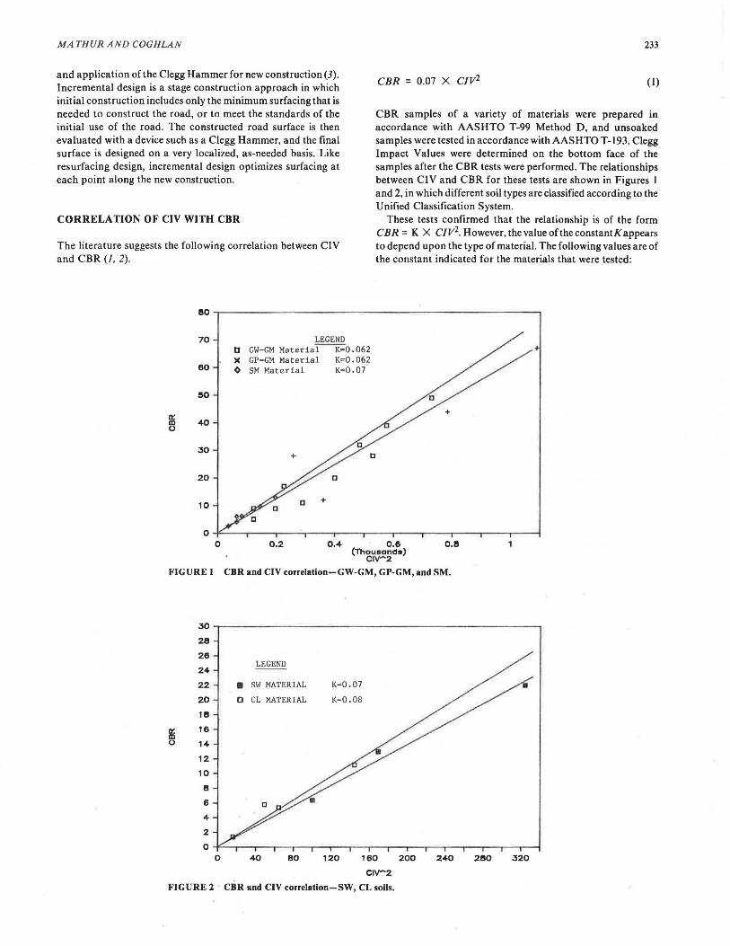
CBR = 0.07 x CIV2 (1)
CBR samples of a variety of materials were prepared in accordance with AASHTO T-99 Method D, and unsoaked samples were tested in accordance with AASHTO T-193. Clegg Impact Values were determined on the bottom face of the samples after the CBR tests were performed. The relationships between CIV and CBR for these tests are shown in Figures 1 and 2, in which different soil types are classified according to the Unified Classification System.
These tests confirmed that the relationship is of the form CBR = K X CIV2. However, the value of the constantK appears to depend upon the type of material. The following values are of the constant indicated for the materials that were tested:
0 0.2 0.4 0.15 0.1!1 (Thoueand•)
crv-2 FIGURE 1 CBR and CIV correlation-GW-GM, GP-GM, and SM.
30
28
26
24
22
20
11!1
Iii 16
0 14
12
10
e 6
4
2
0
LEGEND
• SW MATERIAL
0 CL MATERIAL
K=0.07
K=o.oe
0 160
c1v-2 FIGURE 2 CBR and CIV correlation-SW, CL soils.
40 BO 120 200 240 21!10 320
234
Material K
GW-GM 0.062 GP-GM 0.062 SM 0.07 SW 0.07 CL 0.08
These values are based on a very small number of unsoaked samples from a localized area. However, they indicate that users should verify values of the constant for local soils and aggregates whenever practical. Further testing on soaked CBR samples may also be desirable.
A REVIEW OF THE FOURTH READING FOR THE STANDARD CIV
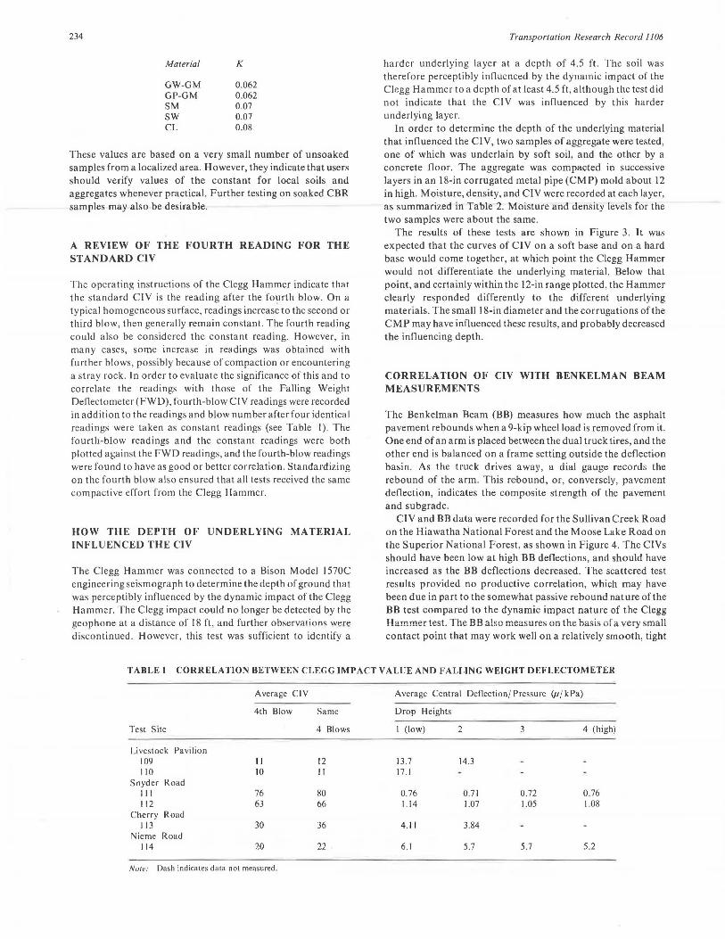
The operating instructions of the Clegg Hammer indicate that the standard ClV is the reading after the fourth blow. On a typical homogeneous surface, readings increase to the second or third blow, then generally remain constant. The fourth reading could also be considered the constant reading. However, in many cases, some increase in readings was obtained with further blows, possibly because of compaction or encountering a stray rock. ln order to evaluate the significance of this and to correlate the readings with those of the Falling Weight Deflectometer (FWD), fourth-blow Cl V readings were recorded in addition to the readings and blow number after four identical readings were taken as constant readings (see Table I). The fourth-blow readings and the constant readings were both plotted against the FWD readings, and the fourth-blow readings were found to have as good or better correlation. Standardizing on the fourth blow also ensured that all tests received the same compactive effort from the Clegg Hammer.
HOW THE DEPTH OF UNDERLYING MATERIAL INFLUENCED THE CIV
The Clegg Hammer was connected to a Bison Model l 570C engineering seismograph to determine the depth of ground that was perceptibly influenced by the dynamic impact of the Clegg Hammer. The Clegg impact could no longer be detected by the geophone at a distance of 18 ft. and further observations were discontinued. However, this test was sufficient to identify a
Transportation Research Record 1106
harder underlying layer at a depth of 4.5 ft. The soil was therefore perceptibly influenced by the dynamic impact of the Clegg Hammer to a depth of at least 4.5 ft, although the test did not indicate that the Cl V was influenced by this harder underlying layer.
In order to determine the depth of the underlying material that influenced the CIV, two samples of aggregate were tested, one of which was underlain by soft soil, and the other by a concrete floor. The aggregate was compacted in successive layers in an 18-in corrugated metal pipe (CMP) mold about 12 in high. Moisture, density, and ClV were recorded at each layer, as summarized in Table 2. Moisture and density levels for the two samples were about the same.
The results of these tests are shown in Figure 3. It was expected that the curves of CIV on a soft base and on a hard base would come together, at which point the Clegg Hammer would not differentiate the underlying material. Below that point, and certainly within the 12-in range plotted, the Hammer clearly responded differently to the different underlying materials. The small l 8-in diameter and the corrugations of the CMP may have influenced these results, and probably decreased the influencing depth.
CORRELATION OF CIV WITH BENKELMAN BEAM MEASUREMENTS
The Benkelman Beam (BB) measures how much the asphalt pavement rebounds when a 9-kip wheel load is removed from it. One end of an arm is placed between the dual truck tires, and the other end is balanced on a frame setting outside the deflection basin. As the truck drives away, a dial gauge records the rebound of the arm. This re-bound, or, conversely, pavement deflection, indicates the composite strength of the pavement and subgrade.
CIV and BB data were recorded for the Sullivan Creek Road on the Hiawatha National Forest and the Moose Lake Road on the Superior National Forest, as shown in Figure 4. The C!Vs should have been low at high BB deflections, and should have increased as the BB deflections decreased. The scattered test results provided no productive correlation, which may have been due in part to the somewhat passive rebound nature of the BB test compared to the dynamic impact nature of the Clegg Hammer test. The BB also measures on the basis of a very small contact point that may work well on a relatively smooth, tight
TABLE I CORRELATION BETWEEN CLEGG IMPACT VALUE AND FALLING WEIGHT DEFLECTOMETER
Average CJV Average Central Deflection/ Pressure (µ/ kPa)
4th Blow Same Drop Heights
Test Site 4 Blows I (low) 2 3 4 (high)
Livestock Pavilion 109 II 12 13.7 14.3 110 10 II 17.1
Snyder Road Ill 76 80 0.76 0.71 0.72 0 .76 112 63 66 1.14 1.07 1.05 1.08
Cherry Road 113 30 36 4.11 3.84
Nie me Road 114 20 22 6.1 5.7 5.7 5.2
Nole: Dash indicates dala nol measured .

MA THUR AND COGHLAN 235
asphalt surface, but may be inappropriate for irregular, loose aggregate surfaces. The performance of further tests may show a trend, but this does not appear warranted.
CORRELATION OF CIV WITH FALLING WEIGHT DEFLECTOMETER
TABLE2 THICKNESS OF MATERIAL THAT INFLUENCES CLEGG IMPACT VALUES
The Falling Weight Deflectometer (FWD) is a trailer-mounted, dynamic loading device for measuring road surface deflection and deflection basin under load. Although it is configured to simulate the impact of a 9-kip wheel, the drop height, weight, and bearing plate size can be varied to provide a range of impacts depending on the materials and the size deflections desired. A series of geophones at known distances along an arm provides the shape of the deflection basin and the center point deflection . The Dynatest FWD that was used in the test recorded deflections in microns(µ) and the plate pressure in kilo Pascals (kPa). This FWD was available through Dr. Lynn Irwin and the Local Roads Program at Cornell University.
Sub grade Base Concrete Base
Dry Dry Ht. Above Density Density Base (in) (pd) Cl Vs (pc!) Cl Vs
0.00 67.4 5 135.8 175 2.00 98.6 5 109.0 38 6.00 115.6 12 120.8 26
10.60 128.0 22 12.75 127.3 13.5
Note: Dash indicates data not measured .
Several aggregate roads near Ithaca , New York, that had different strengths were selected on the basis of local experience. Test sites were selected, C!Ys were taken around proposed
t;_' 0 .!!:. ~ iii al 0
ci C> < '-~
~ C>
~ 0
180 170 160 150 140 130 120 110 100 90 80 70 60 50 40 30 20 10
0
LEGEND
c·P-Y DENSITY, CONCRETE BASE
~1:Y DENSITY, SOFT BASE
CIV. CONCRETE BASE
CIV. SOFT BASE
0 .00 2 .00 4.00 6 .00 8.00 1 o.oo 12.00 14.00 1 6 .00
HEIGHT OF GRAVEL ABOVE BASE
FIGURE 3 Effect of aggregate depth on Clegg values.
lillAll 0.9 MOOSE f,AKE SUJ...L.IVAN CR.
LENGTH, MILES 2.6 10.0 ~ 0.8 TEST PTS. 13 98 :r SURFACE AGG AGG 0 :?; 0.7 o
z 0 0.6 5 ~
0 0.5
w o 0 0
~ 0 .4 o B o
al 0.3
~ ~ o 0
al 0.2 o
o o o o o
0 o B o o8co89ClaBo o
0.1 D 00 0 90 8iis~ 90 o o8 o D 0 CID 10 DO 8 OoD
0 0 20 40
CLEGG IMPACT VALUE
FIGURE 4 Clegg values versus Benkelman Beam deflection.
60
236 Transportation Research Record I 106
2
1.8
1.6 EQUATION
1.4 LOG(FWD) 2.7 - 1.5 LOG(CIV) 1.2
...... 0
0.8 ~ ._,
§ 0.6
0.4
0.2
0
-0.2
-0.4
-0.6 1-
0.8 1 L2 1.4- 1.6 1.8 2 2.2
LOG(CIV)
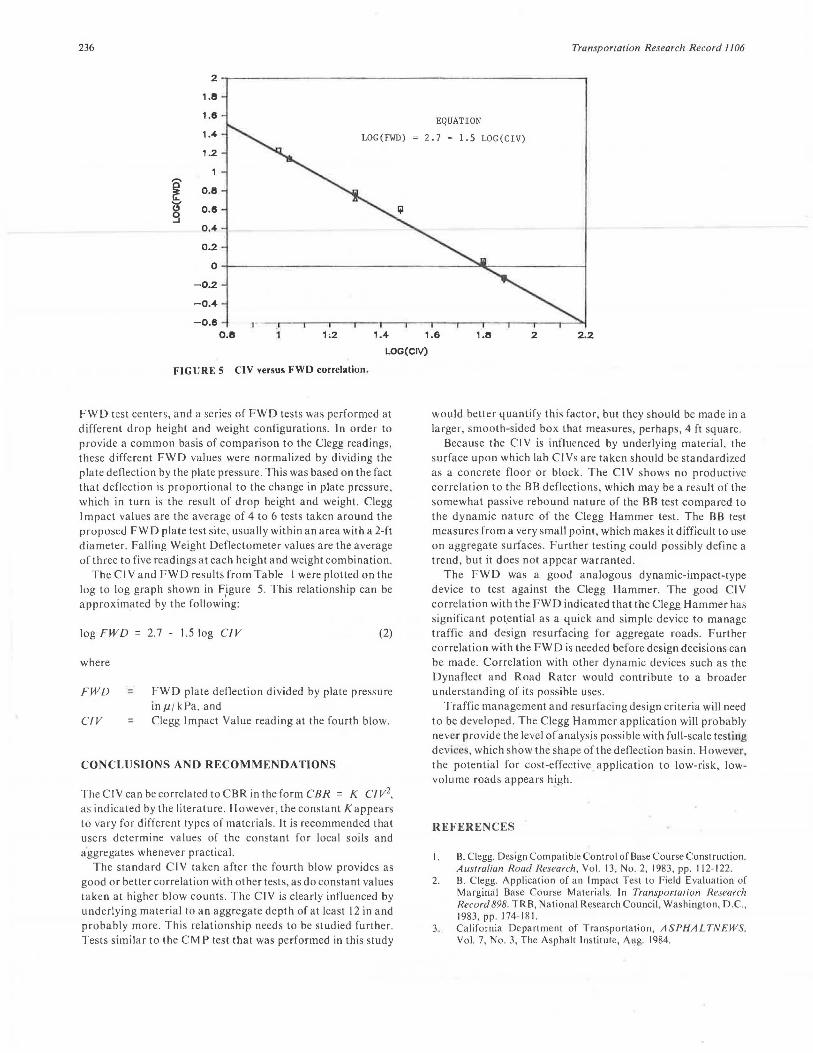
FIGURE 5 CIV versus FWD correlation.
FWD test centers, and a series of FWD tests was performed at different drop height and weight configurations. In order to provide a common basis of comparison to the Clegg readings, these different FWD values were normalized by dividing the plate deflection by the plate pressure. This was based on the fact that deflection is proportional to the change in plate pressure, which in turn is the result of drop height and weight. Clegg Impact values are the average of 4 to 6 tests taken around the pruposeJ FWD plate test site, usually within an area with a 2-ft diameter. Falling Weight Deflectometer values are the average of three to five readings at each height and weight combination.
The Cl V and FWD results from Table I were plotted on the log to log graph shown in F
0igure 5. This relationship can be
approximated by the following:
log FWD = 2.7 - 1.5 log CIV (2)
where
FWD = FWD plate deflection divided by plate pressure inµ/kPa, and
CIV = Clegg Impact Value reading at the fourth blow.
CONCLUSIONS AND RECOMMENDATIONS
TheCIVcanbecorrelatedtoCBRintheformCBR = K CIV2,
as indicated by the literature. However, the constant K appears to vary for different types of materials. It is recommended that users determine values of the constant for local soils and aggregates whenever practical.
The standard CIV taken after the fourth blow provides as good or better correlation with other tests, as do constant values taken at higher blow counts. The Cl V is clearly influenced by underlying material to an aggregate depth of at least 12 in and probably more. This relationship needs to be studied further. Tests similar to the CMP test that was performed in this study
would better quantify this factor, but they should be made in a larger, smooth-sided box that measures, perhaps, 4 ft square.
Because the CIV is influenced by underlying material, the surface upon which lab Cl Vs are taken should be standardized as a concrete floor or block. The Cl V shows no productive correlation to the BB deflections, which may be a result of the somewhat passive rebound nature of the BB test compared to the dynamic nature of the Clegg Hammer test. The BB test measures from a very small point, which makes it difficult to use on aggregate surfaces. Further testing could possibly define a trend, but it does not appear warranted.
The FWD was a good analogous dynamic-impact-type device to test against the Clegg Hammer. The good ClV correlation with the FWD indicated that the Clegg Hammer has significant pot.ential as a quick and simple device to manage traffic and design resurfacing for aggregate roads. Further correlation with the FWD is needed before design decisions can be made. Correlation with other dynamic devices such as the Dynaflect and Road Rater would contribute to a broader understanding of its possible uses.
Traffic management and resurfacing design criteria will need to be developed. The Clegg Hammer application will probably never provide the level oCanalysis possible with full-scale tesLing devi ·,which show the shape of the deflection basin. However. the potential for cost-effective application to low-risk, lowvolume roads appears high.
REFERENCES
I. B. Clegg. Design Compatible Control of Base Course Construction. Australian Road Research, Vol. 13, No. 2, 1983 , pp. 112-122.
2. B. Clegg. Application of an Impact Test to Field Evaluation of Ma1ginal Base Course Materials. In Transpo1·1a1ion Research Record 898. TRB, National Research Council, Washington, D.C., 1983 , pp. 174-181.
3. California Department of Transportation, A SPHALTN EWS, Vol. 7, No. 3, The Asphalt Institute, Aug. 1984.