Transportation Management Plans - IN.gov Management Plans ... 81-3.02(01) Traffic-Control Devices...
41
INDIANA DEPARTMENT OF TRANSPORTATION—2013 DESIGN MANUAL CHAPTER 81 Transportation Management Plans NOTE: This chapter is currently being re-written and its content will be included in Chapter 503 in the future.
Transcript of Transportation Management Plans - IN.gov Management Plans ... 81-3.02(01) Traffic-Control Devices...

INDIANA DEPARTMENT OF TRANSPORTATION—2013 DESIGN MANUAL
CHAPTER 81
Transportation Management
Plans
NOTE: This chapter is currently being re-written and its content will be included in Chapter 503 in the
future.

Page 2 2013 Indiana Design Manual, Ch. 81
TABLE OF CONTENTS
LIST OF FIGURES ........................................................................................................................ 3
81-1.0 GENERAL .......................................................................................................................... 4
81-1.01 Purpose ......................................................................................................................... 4
81-1.02 Application ................................................................................................................... 4
81-1.03 TMP Development ....................................................................................................... 5
81-1.03(01) Procedure ........................................................................................................... 5
81-1.03(02) TMP Team ......................................................................................................... 7
81-1.03(03) TMP-Team Responsibilities .............................................................................. 7
81-1.04 Public-Relations Information ....................................................................................... 8
81-2.0 TRAFFIC-CONTROL MANAGEMENT .......................................................................... 9
81-2.01 Terminology ................................................................................................................. 9
81-2.02 Work-Zone Type ........................................................................................................ 10
81-2.03 Work-Zone Traffic-Control Strategy ......................................................................... 12
81-3.0 TRANSPORTATION-MANAGEMENT-PLAN STRATEGIES .................................... 12
81-3.01 Construction Phasing .................................................................................................. 13
81-3.01(01) Reconstruction by Halves or Sides .................................................................. 13
81-3.01(02) Parallel or Adjacent Reconstruction ................................................................ 14
81-3.01(03) Serial or Segmental Reconstruction ................................................................. 14
81-3.01(04) Complete Closure ............................................................................................. 15
81-3.01(05) Combinations ................................................................................................... 15
81-3.02 On-Site Strategies ....................................................................................................... 16
81-3.02(01) Traffic-Control Devices ................................................................................... 16
81-3.02(02) Capacity ........................................................................................................... 17
81-3.02(03) Other On-Site Considerations .......................................................................... 18
81-3.03 Off-Site Strategies ...................................................................................................... 19
81-3.04 Scheduling .................................................................................................................. 19
81-3.05 Incentive/Disincentive Justification ........................................................................... 20
81-3.06 A + B Bidding ............................................................................................................ 21
81-4.0 COST-EFFECTIVE ANALYSES .................................................................................... 21
81-4.01 General ....................................................................................................................... 21
81-4.02 Cost Evaluation .......................................................................................................... 22
81-4.02(01) On-Site ............................................................................................................. 22
81-4.02(02) Detour .............................................................................................................. 22
81-4.03 QUEWZ Program ....................................................................................................... 23
81-4.03(01) Inputs ................................................................................................................ 23
81-4.03(02) Outputs ............................................................................................................. 24
2013 Indiana Design Manual, Ch. 81 Page 3
FIGURES ...................................................................................................................................... 26
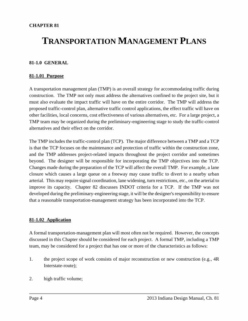
LIST OF FIGURES
Figure Title
81-2A Lane Constriction Work Zone
81-2B Lane Closure Work Zone
81-2C One-Lane, Two-Way Work Zone
81-2D Runaround Work Zones
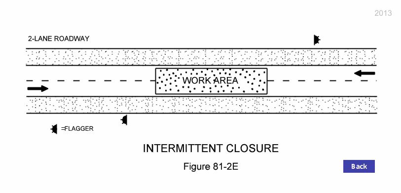
81-2E Intermittent Closure
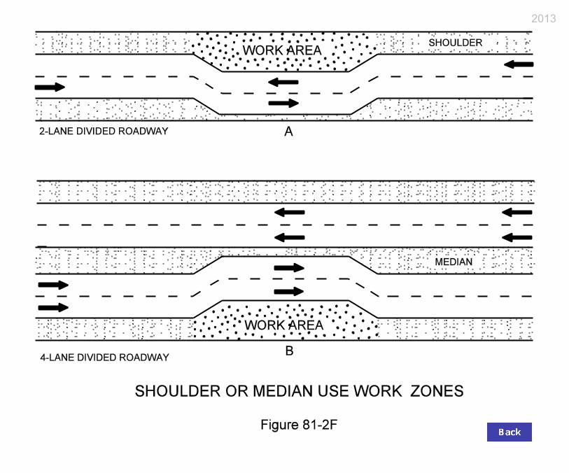
81-2F Shoulder or Median Use Work Zones
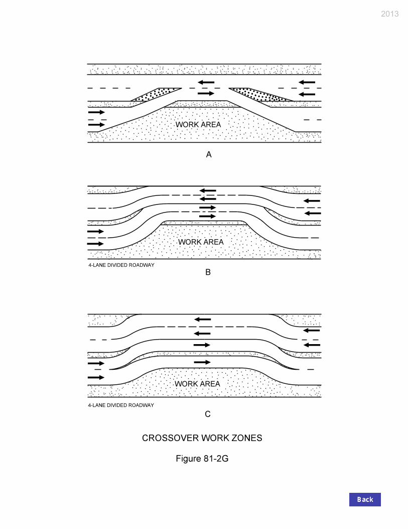
81-2G Crossover Work Zones
81-2H Chart for Identification of Feasible Work Zone Types
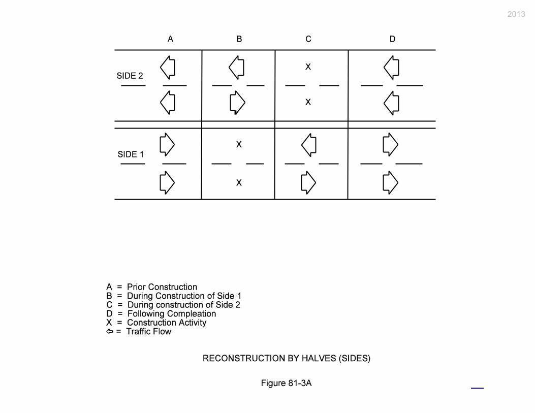
81-3A Reconstruction by Halves (Sides)
81-3B Parallel/Adjacent Reconstruction
81-3C Serial/Segmental Reconstruction
81-3D Editable Worksheet for Determination of Appropriate Incentive/Disincentive Amount
Page 4 2013 Indiana Design Manual, Ch. 81
CHAPTER 81
TRANSPORTATION MANAGEMENT PLANS
81-1.0 GENERAL
81-1.01 Purpose
A transportation management plan (TMP) is an overall strategy for accommodating traffic during
construction. The TMP not only must address the alternatives confined to the project site, but it
must also evaluate the impact traffic will have on the entire corridor. The TMP will address the
proposed traffic-control plan, alternative traffic control applications, the effect traffic will have on
other facilities, local concerns, cost effectiveness of various alternatives, etc. For a large project, a
TMP team may be organized during the preliminary-engineering stage to study the traffic-control
alternatives and their effect on the corridor.
The TMP includes the traffic-control plan (TCP). The major difference between a TMP and a TCP
is that the TCP focuses on the maintenance and protection of traffic within the construction zone,
and the TMP addresses project-related impacts throughout the project corridor and sometimes
beyond. The designer will be responsible for incorporating the TMP objectives into the TCP.
Changes made during the preparation of the TCP will affect the overall TMP. For example, a lane
closure which causes a large queue on a freeway may cause traffic to divert to a nearby urban
arterial. This may require signal coordination, lane widening, turn restrictions, etc., on the arterial to
improve its capacity. Chapter 82 discusses INDOT criteria for a TCP. If the TMP was not
developed during the preliminary-engineering stage, it will be the designer's responsibility to ensure
that a reasonable transportation-management strategy has been incorporated into the TCP.
81-1.02 Application
A formal transportation-management plan will most often not be required. However, the concepts
discussed in this Chapter should be considered for each project. A formal TMP, including a TMP
team, may be considered for a project that has one or more of the characteristics as follows:
1. the project scope of work consists of major reconstruction or new construction (e.g., 4R
Interstate-route);
2. high traffic volume;
2013 Indiana Design Manual, Ch. 81 Page 5
3. is in an urban or suburban area;
4. there may be significant detrimental impacts on mobility for either through or local trips in
the corridor;
5. the facility’s capacity will be significantly reduced (e.g., lane, ramp, or interchange closure);
6. alternate routing will be necessary (e.g., detour routing for hazardous materials);
7. there will be significant impacts on local communities and businesses (e.g., emergency
vehicles, school buses);
8. timing and seasonal impacts may be significant; or
9. there will be significant grade changes.
Where a series of proposed projects are along the same corridor or along corridors of close
proximity, a single TMP covering all such projects should be used. If circumstances prohibit a
single TMP, the individual TMPs should be coordinated.
81-1.03 TMP Development
81-1.03(01) Procedure
Where a TMP is used, the following procedure applies.
1. TMP Determination. The Environmental Policy Team, with input from the district, the
Office of Urban and Corridor Planning, and the Office of Pavement Engineering, will
determine if there is a need for a TMP during the scoping process. The Environmental
Policy Team will collect the initial data and conduct the initial analyses to determine whether
or not a TMP will be required.
2. TMP-Team Selection. Once it has been determined that a TMP is required, the
Environmental Policy Team will initially recommend who the TMP team representatives
will be, based on the purpose, goals, and constraints of the TMP. Section 81-1.03(02) lists
the members for a TMP-team project.
Page 6 2013 Indiana Design Manual, Ch. 81
3. TMP-Team Responsibilities. Section 81-1.03(03) discusses the TMP-team responsibilities
during the scoping process, project design, and construction. The expected level of traffic
impact will dictate the extent and nature of the TMP team’s responsibilities.
4. Preliminary Engineering Studies Report. The Office of Environmental Services’
Environmental Policy Team will incorporate the TMP recommendations into the Engineer’s
Report. If improvements are required to other facilities (e.g., widening of detour route), it is
important that these improvements be implemented as soon as practical prior to construction
of the mainline facility. Local agencies should be provided sufficient opportunity to
complete their improvements before construction begins. Agreements may be necessary
between the State and local agencies to determine cost sharing arrangements or approval of a
local road as an alternate route.
5. Design. During the design phase, it will be the designer’s responsibility to implement the
recommendations of the TMP team. The designer may be required to collect additional data
and conduct additional analyses, as necessary. The TMP team should be consulted if design
or TCP decisions dictate a revision to the proposed TMP. During this project stage,
representatives from local agencies, businesses, homeowner associations, etc., may be added
to the TMP team.
6. Construction. The TMP will be implemented during construction. All significant proposed
changes to the TMP by the district or the contractor must be reviewed with the TMP team
prior to implementation. For a larger project, the district will appoint a TMP coordinator. A
public-relations campaign may be required prior to construction. During construction, the
district will be responsible for collecting data on the TMP so that the TMP team can prepare
a report on the successes and failures of the TMP. See Item 7 below to determine the
applicable data to be collected.
7. Final Report. Upon project completion, the TMP team will prepare a report identifying the
successes and failures of the TMP. This report should discuss the following:
a. an overall statement reflecting the usefulness of the TMP;
b. where changes were necessary to correct oversights in the TMP;
c. what changes were made to the original plan and if they were successful;
d. public reaction to the TMP;
e. the average delay time encountered (e.g., average queue length, slowdown extent);
f. identification of the peak loading times;
g. frequency of legitimate complaints and the nature of the complaints;
h. types of accidents that occurred during construction;
i. suggested improvements or changes for similar future projects; and
2013 Indiana Design Manual, Ch. 81 Page 7
j. what areas of the TMP were successfully implemented.
81-1.03(02) TMP Team
A well-balanced TMP team is an important ingredient for a successful project. The variety of
disciplines represented presents an effective liaison group to meet the various needs of a TMP.
Depending on the project logistics, the team composition may vary from project to project. The
Office of Environmental Services’ Environmental Policy Team will determine the team's
composition. The TMP team may include representatives from the entities as follows:
1. Office of Traffic Engineering;
2. Office of Environmental Services, Environment Assessment Team;
3. Production Management Division;
4. district Office of Traffic;
5. district Office of Design;
6. District Construction Team;
7. Traffic Control Review Committee;
8. FHWA;
9. Local government agency;
10. Planning Division;
11. Office of Communications; and
12. others as deemed necessary (e.g., State Police, hospitals, etc.).
81-1.03(03) TMP-Team Responsibilities
The anticipated traffic impacts will dictate the extent and nature of the TMP team’s responsibilities.
These may include all or part of the functions as follows:
1. collecting data (e.g., traffic counts, accident history, roadway geometrics, proposed
developments, operating speeds);
2. conducting analyses (e.g., capacity analyses, traffic impact studies, safety studies, queuing
analysis);
3. reviewing design alternates;
4. reviewing traffic-control alternates;

Page 8 2013 Indiana Design Manual, Ch. 81
5. reviewing the adequacy of alternate routes (e.g., geometrics, capacity, safety, structural);
6. reviewing on-site and off-site traffic operational improvements (e.g., signal improvements,
parking restrictions);
7. reviewing construction phasing and scheduling alternates;
8. determining the cost of various options and improvements;
9. determining which options are the most cost effective;
10. coordinating with local officials and businesses;
11. coordinating funding and timing with other projects within the corridor;
12. coordinating the design with other TMP plans in the region;
13. planning for emergency responses (incident management);
14. planning rideshare and transit strategies;
15. providing recommendations for the Engineer’s Report;
16. reviewing design and TMP changes made by the designer to ensure that they satisfy the TMP
objectives;
17. reviewing proposed changes made by the contractor or project engineer during construction;
and
18. evaluating and preparing a report on the successes and failures of the TMP after
construction.
81-1.04 Public-Relations Information
For a TMP to be successful, it often requires public involvement and revision of its traveling habits.
The following discusses how the public can become informed and involved in the TMP.
1. Public-Relations Campaign. It is important that the public be informed initially and be kept
informed in a timely manner to ensure that the TMP will work. The elements of a public-

2013 Indiana Design Manual, Ch. 81 Page 9
relations campaign to be considered where significant impacts to traffic are expected are as
follows:
a. information provided to news media;
b. television advertisements;
c. radio advertisements;
d. brochures to be passed out to motorists at key locations;
e. information given to motorists at rest area or welcome centers; or
f. contacting local businesses with large numbers of affected employees or customers.
2. Car and Van Pooling. Car and van pooling campaigns may be considered where it may be
expected to reduce the number of vehicles through a work zone and where it appears
practical to expect a successful campaign.
3. Charter Bus. A charter bus may be considered where it could be expected to draw a large
number of users along a corridor and where it can be shown to be more cost effective than
other alternatives.
4. Transit Incentives. Transit incentives provided to transit customers and companies may be
considered where it can be shown to be more cost effective than other alternatives.
81-2.0 TRAFFIC-CONTROL MANAGEMENT
81-2.01 Terminology
The following definitions are used to define the time required for construction, maintenance, or
utility work.
1. Mobile Work Zone. A work site that is continuously being moved during the period while
work is actively in progress.
2. Short-Duration Work Zone. A work site that occupies a location for up to 1 hour.
3. Short-Term Stationary Work Zone. A work site that requires traffic control in the same
location and where the activity lasts from 1 to 12 hours.
4. Intermediate-Term Stationary Work Zone. A work site that requires traffic control in the
same location and occupies a location from overnight to 3 days.
Page 10 2013 Indiana Design Manual, Ch. 81
5. Long-Term Stationary Work Zone. A work site that requires traffic control in the same
location and where the activity lasts longer than 3 days.
81-2.02 Work-Zone Type
The work zone types that may be considered in a TMP are described below. A work site which is
completely off the roadway and does not disrupt traffic is not addressed, as it will not have a major
effect on traffic.
1. Lane Constriction. This work-zone type is configured by reducing the width of one or more
lanes to retain the number of lanes normally available to traffic. An example of lane
constriction is shown in Figure 81-2A. This application is the least disruptive work-zone
type, but it is only appropriate if the work area is mostly outside the normal traffic lanes.
Narrow lane widths may reduce the facility’s capacity, especially where there is significant
truck traffic. The use of a shoulder as part of the lane width will help reduce the amount of
lane-width reduction that may be required. Where this application is applied for a long-term
work zone, the current lane markings must be obliterated to avoid motorist confusion.
Section 82-3.02 discusses the minimum lane width that must be provided.
2. Lane Closure. This work-zone type closes one or more normal traffic lanes. A lane-closure
example is shown in Figure 81-2B. Capacity and delay analyses may be required to
determine whether serious congestion will result from a lane closure. Use of the shoulder or
median area as a temporary lane will help mitigate the problems arising from the loss in
capacity. Upgrading or replacement of existing pavement or placement of temporary
pavement may be necessary.
3. One-Lane, Two-Way Operation. This work-zone type involves utilizing one lane for both
directions of traffic. Figure 81-2C illustrates a one-lane, two-way operation work zone.
Flaggers or signals are used to coordinate the two directions of traffic. Signing alone may be
sufficient for a short-term work zone on a very low-volume, 2-lane road. This work-zone
type is applicable only for a low-volume road or for a short-term. INDOT has developed a
computer program, WORK, which determines the expected delays and queue lengths for this
work-zone type.
4. Runaround. This work-zone type involves the total closure of the roadway (one or both
directions) where work is being performed and the traffic is rerouted to a temporary roadway
constructed within the highway right-of-way. A runaround example is shown in Figure 81-
2D. This application may require the purchase of temporary right of way and requires
extensive preparation of the temporary roadway.
2013 Indiana Design Manual, Ch. 81 Page 11
5. Intermittent Closure. This work-zone type involves stopping all traffic in one or both
directions for a relatively short period of time to allow the work to proceed. This application
is illustrated in Figure 81-2E. After a specific time, depending on traffic volume, the
roadway is re-opened and all vehicles can travel through the area. This application is
appropriate only on a low-volume roadway or at times of very low volume (e.g., Sunday
morning).
6. Use of Shoulder or Median. This work-zone type involves using the shoulder or the median
as a temporary traffic lane. Figure 81-2F illustrates an example. To use this technique, it
may be necessary to upgrade the shoulder to adequately support the anticipated traffic loads.
This technique may be used in combination with other work-zone types or as a separate
technique.
7. Crossover. This work-zone type involves routing all or a portion of one direction of the
traffic stream across the median to the opposite traffic lanes. This application can also
incorporate the use of the shoulder or a lane constriction to maintain the same number of
lanes. Examples of crossovers are shown in Figure 81-2G. Section 82-3.0 discusses the
geometric design criteria that should be used to develop a crossover. Item 8 below addresses
two-way traffic on a divided facility.
8. Two-Way Traffic on Divided Facility. This work-zone type involves transferring traffic
from a divided facility to two-way operations on one roadway. This application requires
consideration in the planning, design, and construction phases. This application should be
used only if one or more conditions can be applied as follows:
a. an alternate suitable detour is unavailable or is not cost-effective;
b. the use of temporary lanes or shoulders are impractical;
c. construction cannot reasonably occur with one lane open;
d. construction time will be significantly reduced using this option;
e. all safety issues can be reasonably addressed; or
f. pavement and shoulder structures can be reasonably upgraded.
A crossover as discussed in Item 7 above will be required for this application. Section 82-
6.02 discusses the design issues relative to designing a two-way application (e.g., maximum
length). If this application is used, opposing traffic must be separated with positive barriers,
drums, cones, or vertical panels throughout the length of the two-way operation. Section 83-
3.0 discusses the channelization devices that may be used with this layout. One construction
technique involves the reconstruction of the shoulder to allow it to be used as a travel lane.
Once traffic is shifted to a two-way operation, the availability of the shoulder as a third lane
Page 12 2013 Indiana Design Manual, Ch. 81
provides for an improved buffer between the bidirectional traffic and may facilitate
emergency access.
9. Detour. This work-zone type involves total closure of the roadway (one or both directions)
where work is being performed and rerouting the traffic to existing alternate facilities. This
application is desirable where there is unused capacity on a road running parallel to the
closed roadway. In addition to maintaining an official detour, INDOT may be required to
repair a county highway being used as an unofficial detour, per current detour policy.
81-2.03 Work-Zone Traffic-Control Strategy
Selection of the appropriate work-zone type represents one of the most significant elements of a
control strategy. Other elements of a control strategy that should be considered include length of the
work zone, time of work, number of lanes, widths of lanes, traffic speeds, or right of way.
Considering these and other factors, reasonable alternatives can be narrowed to a select few for
further review. Only a small number of feasible work-zone alternatives will emerge for a particular
project and only one may be practical. Identification of these alternates at an early stage in the
planning process can significantly reduce the analysis effort necessary.
Figure 81-2H provides guidelines for identifying feasible work-zone alternates based on roadway
type, lane closure requirements, shoulder width, traffic volume, availability of right of way, and
detour routes. However, every work-zone location will have a wide variation of conditions and an
all-inclusive selection matrix is not practical.
In using Figure 81-2H, local policy and regulations should be recognized. Many jurisdictions have
adopted safety regulations and public convenience policies as safeguards against the unacceptable
impacts of work-zones. These regulations and policies may impose additional constraints regarding
the types of control strategies that can be implemented. Knowing these constraints can help
eliminate infeasible alternates from consideration. The public convenience policies or local
regulations may specify peak hour restrictions, access requirements, noise level limitations, material
storage and handling, excavation procedures, work-zone lengths, and number of traffic lanes that
must remain open.
81-3.0 TRANSPORTATION-MANAGEMENT-PLAN STRATEGIES
In addition to the traffic-control strategies discussed in Section 81-2.0, the following provides brief
summaries of the strategies that may be considered during the development of a TMP. These
strategies must be reviewed and adjusted to meet each project location and situation. The strategies
2013 Indiana Design Manual, Ch. 81 Page 13
discussed below are not all-inclusive, and that other options may be applicable for the location under
consideration.
81-3.01 Construction Phasing
How a project is constructed can greatly impact the traffic flow through the work area. The
following discusses the basic construction phases for freeway reconstruction.
81-3.01(01) Reconstruction by Halves or Sides
This approach involves the reconstruction of all lanes in one direction while the opposing lanes
share the same roadway with traffic in the other direction. This basic concept is illustrated in Figure
81-3A, Reconstruction by Halves or Sides. For a 6-lane facility, traffic is restricted to two lanes in
each direction. This may require using the shoulders, reducing the lane widths, or providing minor
widening. Under certain circumstances, depending on the median width and shoulder configuration,
the inner lane of the two-way operation may not be readily accessible during an emergency.
Providing for emergency turnouts or emergency-vehicle access at appropriate intervals on the
segment under construction may be considered. Some advantages and disadvantages of this strategy
include the following.
1. Advantages.
a. It provides an effective work area.
b. Workers are well-separated from the traffic stream.
c. Work-site access can be arranged with minimal interference from the general traffic
flow.
2. Disadvantages.
a. Crossovers are required.
b. There is a need for positive separation of the traffic streams.
c. There are potential emergency access problems in the inner lane.
d. There may be problems at interchanges with traffic crossing the work zone.

Page 14 2013 Indiana Design Manual, Ch. 81
81-3.01(02) Parallel or Adjacent Reconstruction
This approach involves a variety of lane-closure sequences. A typical sequence of this approach is
as follows, which is also illustrated in Figure 81-3B, Parallel or Adjacent Reconstruction.
1. The existing shoulders are widened and strengthened.
2. Traffic is shifted to the shoulders to allow construction of the inner lanes and median
reconstruction.
3. Traffic is then shifted to the newly-constructed inner lanes to allow reconstruction of the
outer lanes.
4. After construction is completed, traffic is returned to the normal travel lanes.
An advantage of this strategy is that traffic need not cross over the median and does not operate in a
two-way operation. Some of the disadvantages include the following:
1. it provides a more constrained work area for the contractor;
2. work crews are closer to moving traffic; and
3. access to the construction zone involves entry and exit from the travel lanes.
A 6-lane facility is reduced to 2 lanes in each direction and the above sequence is used. If closing
the middle lane, it is preferable to keep the two through lanes on the same side of the construction
zone (e.g., by using the shoulder) versus splitting the two lanes on either side of the construction
zone.
81-3.01(03) Serial or Segmental Reconstruction
This strategy consists of permitting only short segments of the facility to be under construction at
one time. This also requires one or more of the other concepts for traffic accommodation. An
example of this application may include a bridge-deck replacement where each segment can be
completed within a 12-hour time period. This concept is illustrated in Figure 81-3C, Serial or
Segmental Reconstruction.
The advantages of this strategy include relatively short work zones, and few if any interchanges are
impacted at one time. A disadvantage of this strategy is that the overall time period that the facility
is under construction may be lengthened considerably because the construction for each segment
will proceed independently. Therefore, the exposure to the potentially hazardous conditions of a
2013 Indiana Design Manual, Ch. 81 Page 15
work zone for both the traveling public and the work force may be substantially greater than with
one of the other strategies.
81-3.01(04) Complete Closure
Complete closure of the facility or closure of one direction of travel may be an effective strategy.
This strategy may also be effective for only certain hours of the day (e.g., 8 p.m. to 6 a.m. on
weekdays and from 8 p.m. to 8 a.m. on weekends). Some of the advantages and disadvantages of
this strategy include the following.
1. Advantages.
a. Increases the safety for construction workers.
b. Provides cost and time savings.
c. Reduces the overall travel impacts to the public due to reduced construction time.
2. Disadvantages.
a. Potentially significant short-term travel impacts to the public.
b. Potential increase in traffic congestion on other routes.
c. May need to construct a detour or runaround.
d. Potential adverse impact on businesses due to trip suppression (not enough traffic).
e. Potential adverse impact to businesses on alternate routes (too much traffic).
81-3.01(05) Combinations
A combination of construction sequences may be the best strategy. An example is reconstructing
existing shoulders prior to the initiation of parallel construction activities. The sequence of
construction can be as follows.
1. Phase A. Reconstruct shoulders as appropriate to allow one side of the roadway to
accommodate four lanes.
2. Phase B. Shift traffic to the four available lanes on one side of the roadway.
3. Phase C. Shift traffic to the newly constructed side of the roadway using the additional
reconstructed shoulder lane.

Page 16 2013 Indiana Design Manual, Ch. 81
Other combination-type construction sequences involve the reconstruction of interchanges where
both sequential and parallel activities may occur simultaneously. Ramps are reconstructed in a
sequential arrangement, involving closure during construction with temporary detours to adjacent or
alternate freeway-access points.
81-3.02 On-Site Strategies
81-3.02(01) Traffic-Control Devices
The following traffic-control devices applications may be considered when developing a TMP.
1. Changeable-Message Sign. This device may be used where a static sign message is not
sufficient to handle the changing conditions of a work zone (e.g., lane closure, ramp closure,
advise motorists of conditions for which they must possibly react).
2. Additional-Information Panel Sign. This may be used to give the motorist additional
information about a work zone. The message should be pertinent to the likely conditions the
motorist will encounter.
3. Traffic-Signals Interconnection. Consider interconnecting traffic signals where the benefit
of moving traffic through a work zone more efficiently will be enhanced by adding
interconnection between the traffic signals on the system.
4. Traffic-Signal Timing. Traffic-signal timing changes should be considered for all traffic
signals within a work zone for which capacity improvements can be gained. Adding or
deleting signal phases may be required for changes in travel patterns.
5. Highway-Advisory Radio. Consider using highway-advisory radio where changing work-
zone conditions make it important to give the motorist a longer, more accurate message than
can be obtained through the use of signs or other means. This option requires additional
information and signing to alert motorists.
6. Temporary Work-Site Speed-Limit Sign. A reduced regulatory speed limit may be
warranted where work activity may constitute a hazard to traffic, especially for a lane
closure. The Indiana Statutes permit INDOT to establish a reduced work-site speed limit
without an Official Action. Section 83-2.03 provides the criteria for establishing speed-limit
signing in a construction zone.

2013 Indiana Design Manual, Ch. 81 Page 17
7. Flashing-Arrow Sign. A flashing-arrow sign is used to supplement conventional traffic
control devices. It is warranted where additional warning or directional information is
required to assist in merging and controlling traffic through and around the work activity.
Section 83-2.07 provides additional guidance for the use of a flashing-arrow sign.
81-3.02(02) Capacity
Each construction site will affect the capacity of the existing facility. The extent that the roadway is
occupied for work and safety purposes will determine the number of strategies required to
compensate for the loss of capacity. Some of the following capacity strategies may be considered
when developing a TMP.
1. Temporary Parking Restriction. One option to increase capacity is to eliminate on-street
parking to create an additional lane or to reduce traffic conflicts. However, the concerns of
on-street parking for local businesses must be addressed. The elimination can be for only
during a peak traffic-volume period or for the entire 24-h day.
2. Restriction of Trucks. Restriction of trucks may increase the facility’s capacity. However
consideration must be given to State or local ordinances, and the availability and suitability
of alternate routes that the restricted trucks would be required to take.
3. Turn Restrictions. Turn restrictions should be considered where it may be necessary for
capacity or safety reasons. The turn restrictions may be at intersections or drives. Turn
restrictions can be for only during a peak traffic-volume period or for the entire 24-h day.
4. Reversible or Contra-Flow Lane. Consider the use of a reversible or contra-flow lane where
the peak-traffic flow distribution is in one direction for a specified period of time. The use
of such a lane may be limited in use due to the cost of providing and maintaining the daily
changes required. There also may be safety considerations which will need to be evaluated
if such a lane is contemplated.
5. High-Occupancy Vehicle (HOV) Lane. An HOV lane may be considered where a dedicated
lane for high-occupancy vehicles is available and it is desired to discourage use of single-
occupancy vehicles. The use of an HOV lane can be during a peak traffic-volume period or
for the entire 24-h day. Due to the lack of driver familiarity with this type of lane, it is
unlikely that its use will be appropriate.
6. Ramp Metering. Ramp metering may be considered where it is necessary to restrict the
amount of traffic entering a freeway for capacity and safety reasons. Ramp metering may be

Page 18 2013 Indiana Design Manual, Ch. 81
used during peak traffic-volume period or for the entire 24-h day. The impact of ramp
metering on an intersecting road will also need to be considered (e.g., traffic backup).
7. Six-Lane Facility. Where three lanes cannot be maintained in both directions, determine if
three lanes can be provided in one direction with two lanes in the other direction.
81-3.02(03) Other On-Site Considerations
In addition to the above strategies, the following other on-site strategies may be considered in
developing a TMP.
1. Ramp Closure (Short or Intermediate Term). This may be necessary for construction
purposes. If a closure is required, additional signage will be necessary to forewarn the
motorist. Signs should be posted on the affected ramp two weeks in advance to advise the
motorist of the closure date or portion of the day during which the ramp will be closed.
2. Ramp Closure (Long Term). This may be necessary to construct or to improve traffic flow
on the mainline. Local access and business impacts should be considered before deciding on
a long-term ramp closure. Also consider the user costs for a detour route and the capacity
and safety impact of the detour route. Two adjacent ramps should not be closed at the same
time unless necessary for safety reasons.
3. Incident Management. Consider the use of on-site tow trucks for a freeway work zone with
limited to unavailable shoulder width. They should also be considered where an accident or
breakdown would seriously impact traffic flow and cause significant backups and delays.
4. Special Materials. Examine the use of fast-setting or precast concrete, or other special
materials where traffic restrictions must be minimized (e.g., ramp, intersection).
5. Lane Rental by Contractor. In this application, a contractor formulates its bid around the
number of hours that it expects to keep a number of lane-miles closed, and then can earn or
lose money if the actual number is higher or lower than that bid. This concept has not yet
had widespread use.
6. Police Patrol for Speed Control. A police patrol may be required to ensure that vehicular
speeds are at or below the posted speed limit, or for other safety reasons. Because this
requires a special funding mechanism and special provisions, the designer will need to
coordinate this with the Highway Operations Division.

2013 Indiana Design Manual, Ch. 81 Page 19
7. Incentive/Disincentive. Consider adding an incentive/disincentive provision to minimize the
time that a facility may be affected by construction. Section 81-3.05 discusses the types of
work for which an incentive/disincentive provision should be considered.
8. A + B Bidding. If the impact of the construction on traffic is significant, the designer should
consider the A + B bidding incentive. Section 81-3.06 provides information on A + B
bidding.
81-3.03 Off-Site Strategies
Where construction will significantly impact the traffic flow away from the work zone, the following
off-site strategies may be considered in the TMP.
1. Capacity Improvement. Additional improvements on the alternate route may be necessary
for capacity reasons to handle the expected diversion of traffic. Examples of capacity
improvement include prohibiting or restricting parking, turn restrictions, and truck
restrictions, all as described in.81-3.02(01), additional pavement width, or adding a turn lane.
2. Trailblazing to Attraction or Point of Interest. Trailblazing may be necessary to guide the
motorist to an attraction or point of interest where the normal route is closed or seriously
restricted, or where an alternate route to the attraction or point of interest would assist traffic
which would otherwise travel through the work zone.
81-3.04 Scheduling
Project scheduling can affect the overall success of the TMP. For example, restrictive scheduling
may be required to facilitate the opening of a highway prior to a special event. In determining a
construction schedule, the following should be considered.
1. Short Schedule. A schedule to minimize construction activities and disruption to traffic may
be required if motorist user costs are expected to be excessive. However, a short schedule
may increase the cost of the project.
2. Longer Schedule. A longer schedule of construction activities may be cost effective if it
does not significantly increase the adverse impact to the motorist. The contractor may offer
to provide a lower price for a longer schedule.

Page 20 2013 Indiana Design Manual, Ch. 81
3. Time-of-Day or Day-of-Week Restriction. This type of restriction may be necessary if the
work-zone capacity cannot accommodate the expected demand during a peak traffic period
and other measures are not as cost effective. For example, night work may be required to
allow longer work hours than can be provided between morning and afternoon peaks and to
decrease the excessive traffic delays or congestion associated with lane closures during the
daytime.
4. Project Staging. Project staging or completing smaller portions of a project one portion at a
time may be necessary to limit disruption to traffic. However, construction activity in the
same area over several seasons should be discouraged.
5. Combining with Other Work. Projects within a corridor may be combined or scheduled at
the same time where practical, pending available funding, to minimize impacts to the
motoring public.
81-3.05 Incentive/Disincentive Justification
Incentive/disincentive is used to minimize the time that a facility may be affected by construction.
The contractor is provided additional funds if the project is completed early, or is assessed damages
if the project is not completed on time. Due to administrative concerns of implementing this
concept, limit incentive/disincentive to a project that has one or more of the characteristics as
follows:
1. high traffic volume occurs in an urban area;
2. it completes a gap in the highway facility;
3. it severely disrupts traffic or highway services;
4. it significantly increases road user’s costs;
5. it significantly impacts adjacent neighborhoods or businesses;
6. it replaces a major bridge that is out of service; or
7. it includes lengthy detours.
Figure 81-3D consists of the Department’s worksheet for determining the appropriate
incentive/disincentive amount. An editable version of this form may also be found on the
Department’s website at www.in.gov/dot/div/contracts/design/dmforms/. An incentive/disincentive
justification request should be forwarded to the Contract Administration Division’s Office of
Contracting as soon as practical due to the time required for the Central Office to process the
request.

2013 Indiana Design Manual, Ch. 81 Page 21
81-3.06 A + B Bidding
Where the impact of the work site is significant, an A + B bidding incentive may be used to
encourage the contractor to minimize these impacts by reducing the exposure time. A + B bidding
consists of two parts as follows.
1. Part A. The total dollar amount required to complete the work.
2. Part B. The total dollar amount based on peak- and non-peak-traffic-volume lane-closure
periods, and the total contract days proposed by the contractor to complete the work.
Part A is determined using the contractor’s unit prices and the estimate of quantities determined by
the Department. Part B is established by adding together the costs for each of the following:
1. peak-traffic-volume lane-closure periods = (no. of periods) x (cost / lane / period);
2. non-peak-traffic-volume lane = (no. of periods) x (cost / lane / period); plus
3. Contract days = (no. of days) x (cost / day)
The contractor is required to estimate the number of periods that the facility will be closed during
peak- and non-peak-traffic-volume hours and the overall number of calendar days required to
complete the contract. The cost for each of the above items is determined by the Department and is
the same for each bidder.
A + B bidding is used only for comparison purposes to determine a successful bidder. It is not used
to determine payments to the contractor. A + B bidding is used in conjunction with
incentive/disincentive as discussed in Section 81-3.05. Before adding an A + B bidding special
provision to a contract, the designer should coordinate its use with the Highway Operations Division
and the district construction engineer.
81-4.0 COST-EFFECTIVE ANALYSES
81-4.01 General
There may be more than one option that will address the problem of traffic congestion during
construction. To determine the most appropriate option, the user will need to compare the benefits
and costs of each to determine the most appropriate option. Chapter 50 provides information on
economic analyses relative to benefit/cost analysis and safety-cost analysis. The user should review
Chapter 50 in conjunction with the following to determine which option will be the most cost-
effective.
Page 22 2013 Indiana Design Manual, Ch. 81
A project may not have alternate methods of maintaining traffic. The user-cost calculations will not
be required. However, for a project with incentive/disincentive, the user costs must still be
determined.
There are computer programs available which the designer may use to determine the cost
effectiveness of the various options and alternates. For a freeway, INDOT uses the QUEWZ
program. The Department’s application of this program is further described in Section 81-4.03.
81-4.02 Cost Evaluation
81-4.02(01) On-Site
If determining the costs of on-site options (e.g., runaround, lane closure, shoulder use), the designer
should consider the following:
1. right-of-way cost (temporary and permanent);
2. additional construction costs;
3. effect on wetlands;
4. vehicular delay;
5. user costs (including detour user costs);
6. accident potential; and
7. driving time.
If determining the effect of each on-site option, the designer should also consider the effect the
selected option will have on an unofficial detour (i.e., a detour which a motorist selects on his or her
own to avoid the construction area). The designer should see the INDOT Detour Policy regarding an
unofficial local detour.
81-4.02(02) Detour
For an official detour or unofficial detour, the designer must determine the total cost of the detour.
To determine the daily detour user costs, use the following equations.
1. Detour User Cost = (Cost in Lost Time) + (Cost in Extra Distance Traveled).
2. Cost of Lost Time = (No. of vehicles detoured) x (increase in travel time per vehicle, h) x
(value of motorist's time)

2013 Indiana Design Manual, Ch. 81 Page 23
3. Increase in travel time = (length of detour, mi / average detour travel speed, mph) – (length
of construction zone, mi / average travel speed through construction zone, mph)
4. Cost in Extra Travel Distance = (net increase in length of travel, mi) x (vehicle operating
expense),
Where:
The net increase in length of travel distance is the difference between the detour and
non-detour distances.
The value of motorist time not only considers lost wages but also lost free time. A
value from $10 to $15 per hour is used.
The vehicular operating expense includes fuel, maintenance, and depreciation costs,
and is set at $0.25 per mile.
In addition to the above detour user costs, the designer must add the cost for improvements needed
to the detour route (e.g., repaving, pavement widening, signal improvements). The designer should
also consider the effect the detour will have on the community and local businesses.
81-4.03 QUEWZ Program
The Department uses the computer program QUEWZ for a freeway project to determine the queue
length and user costs that are associated with work-zone lane closures. Based on the type of lane
closure, traffic volume, time schedules, etc., the program will provide the user with the expected
queue length and estimated user costs. The Office of Environmental Services’ Environment
Assessment Team may use this program during the preliminary-engineering stage to compare the
various options. The designer may use this program to ensure that the proposed traffic-control plan
is still cost effective. The program user should review the user’s manual to determine how to use the
program.
81-4.03(01) Inputs
The user must provide inputs into the program as follows:
1. lane-closure configurations;

Page 24 2013 Indiana Design Manual, Ch. 81
2. the schedule of work activities (e.g., work activity hours, lane-constriction hours); and
3. the traffic volume approaching the freeway segment.
The program provides default values for the following:
1. cost update factor;
2. percentage of trucks;
3. speeds and volumes at various points on a speed-volume curve;
4. capacity of a lane in the work zone;
5. maximum acceptable delay to the motorist; and
6. critical length of queue.
To obtain meaningful results, the designer should consider revising the default values to satisfy the
site location. For example, the program assumes that if a queue lasts longer than 20 min some
motorists will divert. To account for actual queues and the corresponding user costs, the designer
may need to adjust the 20-min time frame to satisfy the project situation. The designer should
review the user’s manual to determine if the default values are applicable to the location under
consideration.
81-4.03(02) Outputs
QUEWZ has two output options: road-user cost and lane-closure schedule. The road-user-cost
output option analyzes a specified lane-closure configuration and schedule of work activities, and
provides estimates of traffic volume, capacity, speed, queue length, diverted traffic, and additional
road user costs for each hour affected by the lane closure. The lane-closure-schedule option
summarizes the hours of the day during which a given number of lanes can be closed without
causing excessive queuing.
In addition to the values obtained from the program, supplemental user-cost calculations may be
required where changes are expected based on existing traffic patterns and volume. Supplemental
calculations for a detour are required where an exit or entrance ramp within the construction zone
(including that using crossovers) will be closed and where the designer judges that the QUEWZ
program is not properly estimating the full amount of diverting mainline traffic.
Additional detour user-cost calculations should be conducted if an exit ramp is to be closed.
Experience has shown that most or all of the traffic that would have used a ramp if it was open will
divert from the mainline before the construction zone. Therefore, the exit-ramp volume should be
deleted from the input mainline volume before using QUEWZ.

2013 Indiana Design Manual, Ch. 81 Page 25
A closed entrance ramp may or may not lead to changes in the input values for QUEWZ.

2013

2013

2013

2013
2013
2013
2013

2013
2013

2013

2013

INCENTIVE / DISINCENTIVE (I/D) AMOUNT DETERMINATION English-Units Project
I. PROJECT CHARACTERISTICS
Route Contract No. Project No. Des. No. District: National Highway System (NHS) Route? Yes No Location: Estimated Start Date of Work: Estimated Completion Date Without I/D: Estimated Contract Amount: $ * Estimated Local-Traffic AADT: Trucks % * Estimated Through-Traffic AADT: Trucks % ** Length of Local-Traffic Detour: mi ** Length of Through-Traffic Detour: mi
* Use best judgment for breakdown of traffic. ** Use official detour for through traffic.
II. I/D CONSIDERATIONS
Contract restrictions (e.g., utility adjustments, R/W acquisitions, permits, environmental constraints, closure times, special fabrication requirements):
Reasons for proposing I/D:
Critical construction elements:
Estimated Completion Date With I/D: Estimated I/D Amount: $ per day Proposed I/D Time: Calendar Days
Maximum I/D Adjustments = (I/D Amount) x (I/D Time):
$ x days = $
2013
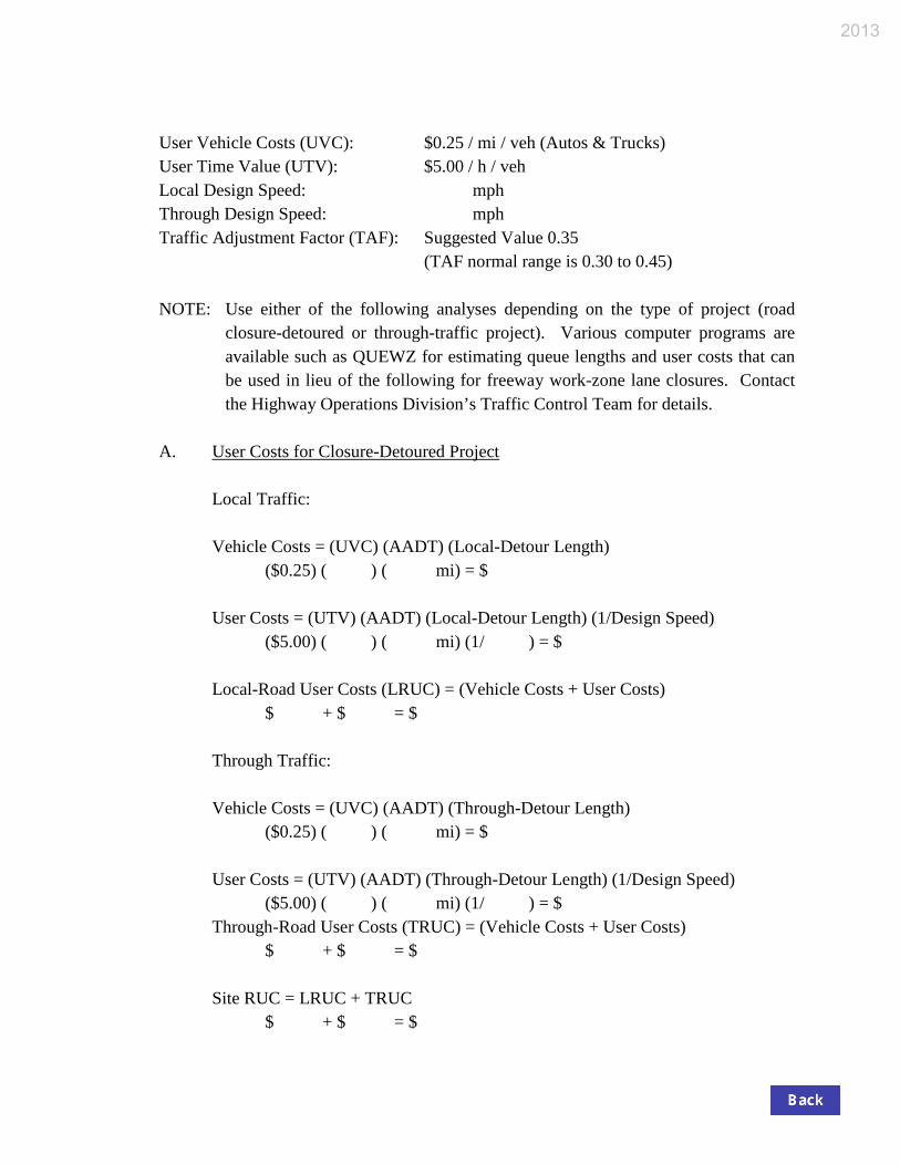
User Vehicle Costs (UVC): $0.25 / mi / veh (Autos & Trucks) User Time Value (UTV): $5.00 / h / veh Local Design Speed: mph Through Design Speed: mph Traffic Adjustment Factor (TAF): Suggested Value 0.35
(TAF normal range is 0.30 to 0.45)
NOTE: Use either of the following analyses depending on the type of project (road closure-detoured or through-traffic project). Various computer programs are available such as QUEWZ for estimating queue lengths and user costs that can be used in lieu of the following for freeway work-zone lane closures. Contact the Highway Operations Division’s Traffic Control Team for details.
A. User Costs for Closure-Detoured Project
Local Traffic:
Vehicle Costs = (UVC) (AADT) (Local-Detour Length)
($0.25) ( ) ( mi) = $
User Costs = (UTV) (AADT) (Local-Detour Length) (1/Design Speed) ($5.00) ( ) ( mi) (1/ ) = $
Local-Road User Costs (LRUC) = (Vehicle Costs + User Costs)
$ + $ = $
Through Traffic:
Vehicle Costs = (UVC) (AADT) (Through-Detour Length) ($0.25) ( ) ( mi) = $
User Costs = (UTV) (AADT) (Through-Detour Length) (1/Design Speed)
($5.00) ( ) ( mi) (1/ ) = $ Through-Road User Costs (TRUC) = (Vehicle Costs + User Costs)
$ + $ = $
Site RUC = LRUC + TRUC $ + $ = $
2013

B. Disruption Costs for Through-Traffic Project
NOTE: The following analysis provides delay cost for through traffic only. If
the project includes ramp or intersection closures, the analysis from Part A above can be added to the through-traffic disruption costs or other factors commensurate upon the scope of the particular project.
Vehicle Costs = (UVC) (AADT) (TAF)
($0.25) ( ) ( ) = $
User Costs = (UTV) (AADT) (TAF) ($5.00) ( ) ( ) = $
Traffic Disruption Costs = (Vehicle Costs + User Costs)
$ + $ = $
C. General Comments
D. Other Factors to Consider. Is the route on or near one or more of the following?
School: Yes No Hazardous-Materials Route: Yes No Hospital: Yes No Special or Seasonal Event: Yes No Emergency Route: Yes No Local Business: Yes No
III. SUMMARY
Recommended Maximum I/D Time: Calendar Days Recommended I/D Date: Recommended Maximum I/D Amount: $ per Day Is I/D amount > 5% of contract amount? Yes No
NOTE: If the I/D amount per day is greater than the Site RUC or Traffic User Costs, I/D
is not justified. IV. APPROVALS
2013

A. Non-NHS Project
Prepared By: Date
Recommended By: ____________________________ Date __________ Field Construction Engineer, Construction Mgmt.. Div.
If I/D ≤ 5% of contract amount,
Approved By: ____________________________ Date __________
Director, Construction Management Division
If I/D > 5% of contract amount, Approved By: ____________________________ Date __________
Chief Highway Engineer
Received By: ____________________________ Date __________ Contracting Office Manager, Contract Administration Division
2013

B. NHS Project
Prepared By: Date
Recommended By: ____________________________ Date __________ Field Construction Engineer, Construction Mgmt.. Div.
Approved By: ____________________________ Date __________
Chief Highway Engineer
Received By: ____________________________ Date __________ Contracting Office Manager, Contract Administration Division
NHS Exemption: Yes No
If No, this document must be submitted to FHWA for approval. Approved By: ____________________________ Date __________
Federal Highway Administration
2013