Transport Resource Management within UMTS Radio … · LTKK Lappeenranta University of Technology...
120
LTKK Lappeenranta University of Technology Department of Information Technology Transport Resource Management within UMTS Radio Network Subsystem The Department Council of the Department of Information Technology confirmed the topic of this Master’s Thesis on 15 th of April 2002. Examiner: Professor Jan Voracek Supervisor: Juha Sipilä, M. Sc. Instructor: Tatiana Issaeva, M. Sc. Author: Zimenkov Andrei Address: Maasälväntie 16R 109, 00710, Helsinki, Finland Mobile +358 50 3878528 April 22, 2002
Transcript of Transport Resource Management within UMTS Radio … · LTKK Lappeenranta University of Technology...

LTKK
Lappeenranta University of Technology Department of Information Technology
Transport Resource Management within UMTS Radio Network Subsystem
The Department Council of the Department of Information Technology confirmed the topic of this Master’s Thesis on 15th of April 2002. Examiner: Professor Jan Voracek Supervisor: Juha Sipilä, M. Sc. Instructor: Tatiana Issaeva, M. Sc. Author: Zimenkov Andrei
Address: Maasälväntie 16R 109, 00710, Helsinki, Finland
Mobile +358 50 3878528
April 22, 2002

ii
LAPPEENRANTA UNIVERSITY OF TECHNOLOGY Department of Information Technology
ABSTRACT OF MASTER'S THESIS
Author: Andrei Zimenkov Name of the thesis: Transport Resource Management within UMTS Radio
Network Subsystem Translation in Finnish: Siirtoresurssien hallinta UMTS radioaliverkkojärjestelmässä Date: 22nd April 2002 Original language: English Number of pages: 120
Examiner: Professor Jan Voracek Supervisor: Juha Sipilä, M. Sc. Instructor: Tatiana Issaeva, M. Sc.
At the moment the most challenging research and development in telecommunication industry is concentrated around the third generation mobile telecommunication systems, often referred to as 3G. The specifications of 3G systems have reached the first stable releases and their commercial deployment is on the way in Japan and Europe. The Universal Mobile Telecommunications System (UMTS) is one of the 3G systems. This thesis gives an overview of the UMTS system and functionality of its network elements. The main attention is paid to the UMTS Terrestrial Radio Access Network (UTRAN) and more specifically to the Radio Network Subsystem (RNS) constituted by Radio Network Controller (RNC) and a set of Node Bs belonging to it. The RNC and Node Bs are connected via the open interface commonly referred to as an Iub interface. The Iub interface provides the RNC with the means to control Node B via exchanging signalling messages and enables the efficient and reliable transmission of user traffic within RNS. For that it owns the transport resources that must be thoroughly managed. The transport resource management over the Iub interface is the main topic of this thesis. The transport network architecture is given and explained. Also the set of protocols as well as functional units running at the Iub interface and contributing to the transport resource management are presented and described in details. The main attention is paid to the application protocols both in Transport Network and Radio Network layers of the interface and interaction between them. These protocols are Node B Application Part (NBAP) and Access Link Control Application Part (ALCAP). The implementation of the NBAP prototype and Node B Manager functional unit is presented as a practical part of this thesis Keywords: UMTS, 3G, Iub interface, transport resource management, protocol, NBAP, Node B Manager, ALCAP

iii
LAPPEENRANNAN TEKNILLINEN KORKEAKOULU Tietotekniikan osasto
DIPLOMITYÖN TIIVISTELMÄ
Tekijä: Andrei Zimenkov Työn nimi: Transport Resource Management within UMTS Radio
Network Subsystem Suomenkielinen käännös: Siirtoresurssien hallinta UMTS radioaliverkkojärjestelmässä Päivämäärä: 22.04.2002 Työn kieli: englanti Sivumäärä: 120
Tarkastaja: Professori Jan Voracek Valvoja: Juha Sipilä, DI Ohjaaja: Tatiana Issaeva, DI Tällä hetkellä haastavin telekommunikaatioteollisuuden tutkimus – ja kehitystoiminta on keskittynyt kolmannen sukupolven matkapuhelinjärjestelmien ympärille. Järjestelmien standardointityössä on saatu aikaiseksi ensimmäiset vakaat spesifikaatioversiot ja kaupallista toimintaa ollaan parhaillaan aloittelemassa Japanissa ja Euroopassa. Eräs kolmannen sukupolven järjestelmistä on UMTS (Universal Mobile Telecommunications System). Tämä diplomityö antaa yleiskuvan UMTS järjestelmästä ja sen eri verkkoelementtien toiminnallisuuksista. Päähuomio on kiinnitetty radioverkkojärjestelmään (UMTS Terrestrial Radio Access Network) ja erityisesti sen radioaliverkkojärjestelmään (Radio Network Subsystem), joka koostuu radioverkonohjaimesta (Radio Network Controller) ja joukosta siihen kuuluvia tukiasemia (Node B). Radioverkonohjain ja tukiasemat on yhdistetty avoimen rajapinnan kautta jota kutsutaan Iub -rajapinnaksi. Rajapinta tarjoaa radioverkonohjaimelle mahdollisuuden kontrolloida tukiasemia signalointiviestien avulla ja mahdollistaa tehokkaan ja luotettavan käyttäjätiedon siirron radioaliverkkojärjestelmän sisällä. Tämän diplomityön pääasiallinen sisältö on siirtoresurssien hallinta Iub -rajapinnan ylitse. Työssä esitellään ja selitetään siirtoverkon arkkitehtuuri. Myös kaikki Iub:ssä sijaitsevat protokollat ja toiminnalliset yksiköt jotka vaikuttavat siirtoresurssien hallintaan esitellään ja kuvataan yksityiskohtaisesti. Päähuomio on kiinnitetty sovellusprotokolliin sekä rajapinnan siirtoverkko- että radioverkkokerroksella sekä näiden protokollien väliseen vuorovaikutukseen. Kyseiset protokollat ovat Node B Application Part (NBAP) ja Access Link Control Application Part (ALCAP). Työn toteutusosassa käydään lävitse NBAP –protokollan prototyypin ja Node B Manager –toiminnallisen yksikön prototyypin implementaatio. Avainsanat: UMTS, 3G, Iub interface, transport resource management, protocol, NBAP, Node B Manager, ALCAP
iv
ACKNOWLEDGEMENTS
This Master's Thesis has been done in the Mobile Networks Laboratory of Nokia
Research Center, Helsinki.
I would like to thank my supervisor Juha Sipilä and project instructor Tatiana Issaeva
for giving me an opportunity to write this thesis based on the work conducted within the
project 3G SDL Library. In addition I express my gratitude to them for very valuable
comments and suggestions about the content of the thesis and continuous guidance during the
work in laboratory. Special thanks to Ari Ahtiainen for the help with formulation of topic and
structure of the thesis.
Above all I would like to express my appreciation to all the people who introduced me
to the Mobile Network Laboratory and created the friendly working environment around me,
who answered my stupid and not so questions and helped me to become more and more
proficient in telecommunications field.
Finally I would like to thank all the people in Lappeenranta Univerversity of
Technology who contributed to organising the Internation Master's Program in Information
Technology for giving the opportunity to study in Finland and helping with all the problems
arising during the study. This personally concerns Jan Voracek and Nina Kontro-Vesivalo.
Also thanks to my study colleagues for joyous and encouraging study in Lappeenranta.
Helsinki, 22nd of April, 2002
Andrei Zimenkov
v
TABLE OF CONTENTS
ABSTRACT OF MASTER'S THESIS ...............................................................................................................II
DIPLOMITYÖN TIIVISTELMÄ..................................................................................................................... III
ACKNOWLEDGEMENTS ................................................................................................................................IV
TABLE OF CONTENTS ..................................................................................................................................... V
ABBREVIATIONS............................................................................................................................................ VII
INTRODUCTION .................................................................................................................................................1
1. UMTS SYSTEM............................................................................................................................................4
1.1 THE ROLE OF UMTS IN 3G STANDARDIZATION ..........................................................................................4
1.2 BASIC CONCEPTS IN UMTS .........................................................................................................................9
1.2.1 WCDMA Radio Interface ................................................................................................................. 10
1.2.1.1 WCDMA channels.................................................................................................................................. 13
1.2.2 UMTS Terrestrial Radio Access Network ........................................................................................ 16
1.2.2.1 Transport Technology in UTRAN .......................................................................................................... 18
1.2.3 Core Network ................................................................................................................................... 19
1.3 GENERIC MODEL OF UTRAN INTERFACES ................................................................................................ 21
1.4 PROTOCOL STACK IN UTRAN ................................................................................................................... 26
2. Iub INTERFACE ........................................................................................................................................ 30
2.1 PROTOCOL STACK OF THE IUB INTERFACE ................................................................................................. 31
2.2 LOGICAL MODEL OF THE NODE B .............................................................................................................. 33
2.2.1 Radio Network Logical Resources ................................................................................................... 35
2.2.2 Transport Network Logical Resources............................................................................................. 36
2.3 THE STRUCTURE OF IUB TRANSPORT ......................................................................................................... 38
2.3.1 Transport Network Control Plane at the Iub interface .................................................................... 38
2.3.2 Transport Network User Plane at the Iub interface......................................................................... 41
3. THE Iub PROTOCOLS INVOLVED INTO TRANSPORT RESOURCE MANAGEMENT ............ 43
3.1 FRAME PROTOCOLS AND SYNCHRONIZATION MODEL ................................................................................ 43
3.1.1 Frame structure ............................................................................................................................... 49
3.1.2 Synchronization model in the UTRAN ............................................................................................. 52
3.2 MACRO DIVERSITY COMBINING................................................................................................................ 54
3.3 ATM STACK AND ADAPTATION LAYERS.................................................................................................... 59
3.3.1 Basic concepts of ATM..................................................................................................................... 59
3.3.2 ATM Adaptation Layers ................................................................................................................... 62
3.3.2.1 ATM Adaptation Layer 2........................................................................................................................ 64
3.3.2.2 ATM Adaptation Layer 5........................................................................................................................ 67

vi
3.4 ALCAP PROTOCOL ................................................................................................................................... 68
3.5 NBAP AS A CONTROL PLANE PROTOCOL OVER THE IUB INTERFACE.......................................................... 73
3.5.1 NBAP services.................................................................................................................................. 76
3.5.2 Example of signalling procedure ..................................................................................................... 78
4. IMPLEMENTATION OF NBAP AND NODE B MANAGER............................................................... 86
4.1 GENERAL INFORMATION AND DEVELOPMENT STAGES ............................................................................... 86
4.2 DEVELOPMENT ENVIRONMENT.................................................................................................................. 89
4.3 NBAP SDL IMPLEMENTATION.................................................................................................................. 94
4.4 NODE B MANAGER SDL IMPLEMENTATION............................................................................................ 102
4.5 EXPERIENCE ............................................................................................................................................ 105
5. CONCLUSION.......................................................................................................................................... 107
REFERENCES .................................................................................................................................................. 109
vii
ABBREVIATIONS
2G The Second Generation Mobile Communication Systems 3G The Third Generation Mobile Communication Systems 3GPP 3rd Generation Partnership Project AAL2 ATM Adaptation Layer 2 AAL5 ATM Adaptation Layer 5 AICH Acquisition Indication Channel ALCAP Access Link Control Application Part ARIB Association for Radio Industry and Business ANSI American National Standards Institute ASN.1 Abstract Syntax Notation One ATM Asynchronous Transfer Mode AUC Authentication Center BCH Broadcast Channel BER Bit Error Rate BS Base Station BSS Base Station Subsystem CASE Computer Aided Software Engineering CASN Compiler for ASN.1 CC Call Control CDMA Code Division Multiple Access CM Connection Management CN Core Network CPCH Common Packet Channel CRNC Controlling RNC CS Circuit-Switched CVOPS C-based Virtual Operating System DCH Dedicated Channel DRNC Drift RNC DL Downlink DPCCH Dedicated Physical Control Channel DPDCH Dedicated Physical Data Channel DS-CDMA Direct Sequence Code Division Multiple Access DSCH Downlink Shared Channel FACH Forward Access Channel FDD Frequency Division Duplex FDMA Frequency Division Multiple Access FER Frame Error Rate FH-CDMA Frequency Hopping Code Division Multiple Access FP Frame Protocols EIR Equipment Identity Register EP Elementary procedure
viii
ETSI European Telecommunication Standards Institute GGSN Gateway GPRS Support Node GMSC Gateway Mobile Services Switching Center GPRS General Packet Radio Service GSM Global System for Mobile Communications HLR Home Location Register ID Identifier IP Internet Protocol ISDN Integrated Services Digital Network ISO International Standards Organisation ITU International Telecommunication Union ITU-T Telecommunication Standardisation Sector of ITU MAC Medium Access Control MC-CDMA Multi Carrie Code Division Multiple Access ME Mobile Equipment MM Mobility Management MSC Mobile Services Switching Center MSC Message Sequence Chart NBAP Node B Application Part NSS Network and Switching Subsystem O&M Operation and Maintenance OSI Open Systems Interconnection PCCPCH Primary Common Control Physical Channel PCH Paging Channel PCPCH Physical Common Packet Channel PDU Protocol Data Unit PER Packet Encoding Rules PID Process Identifier PLMN Public Land Mobile Network PDSCH Physical Downlink Shared Channel PRACH Physical Random Access Channel PS Packet-Switched PSTN Public Switched Telephone Network QoS Quality of Service QPSK Quadrature Phase Shift Keying RAB Radio Access Bearer RACH Random Access Channel RAN Radio Access Network RANAP Radio Access Network Application Part RF Radio Frequency RLC Radio Link Control RNC Radio Network Controller RNS Radio Network Subsystem
ix
RNSAP Radio Network Subsystem Application Part RRC Radio Resource Control RSM Radio subsystem management RTS Run-time system SCCP Signalling Connection Control Part SCCPCH Secondary Common Control Physical Channel SCH Synchronisation Channel SDL Specification and Description Language SDT SDL Design Tool SF Spreading Factor SGSN Serving GPRS Support Node SIR Signal-to-Interference Ratio SM Session Management SMS Short Message Service SRNC Serving Radio Network Controller SS7 Signalling System Number 7 SSCF Service Specific Co-ordination Function SSCOP Service Specific Connection Oriented Protocol TDD Time Division Duplex TDMA Time Division Multiple Access TRM Transport Resource Management TTP Traffic Termination Point UE User Equipment UL Uplink UMTS Universal Mobile Telecommunications System UNI User Network Interface USIM UMTS Subscriber Identity Module UTRAN UMTS Terrestrial Radio Access Network VLR Visitor Location Register WCDMA Wideband Code Division Multiple Access

1
INTRODUCTION
During last two decades on the background of booming growth in telecommunication
industry we have witnessed of fast development of cellular networks from introduction of 1st
generation systems through deep penetration of 2nd generation systems in social life all over
the world, towards their smooth evolution to the global 3rd generation systems bringing new
range of services and bright shiny perspectives, from mobile telephony as a mean of
communication between people to the "Information Society" concept where mobile
communications in tight convergence with Internet and multimedia is viewed as an integral
part of business and everyday life.
The 2nd generation mobile systems are those that are currently most widely used all over
the world. One of their representative is the GSM (Global System for Mobile
communications), which is nowadays deployed worldwide. But was originally standardized
by the ETSI (European Telecommunications Standards Institute) only for European
perspective. In some parts of the world the other standards specified by the local
standardization bodies and therefore not compartible with GSM are also used. This became
one of the shortcoming of the 2nd generation mobile systems that they cannot be used
globally. Another demerit of the GSM-like systems is the inability to support high and
variable data rates. Initially the 2nd generation systems were inteded to provide mainly low bit
rate services such as voice transmissions. But current trends are such that there is a
continuously growing need for convergence between Internet and multimedia technologies
and mobile telephony. Current radio and transport technologies utilized in existing 2nd
generation mobile sysems, and GSM in particular, cannot meet any longer rapidly growing
requirements imposed on services to be provided. The intensive research in that area has led
to creation of new family of standards referred to as a 3rd generation (3G) mobile
telecommunication systems.
As the successors of the 2nd generation systems the 3G systems are intended to
eliminate the shortcomings of their predecessors. First of all this means that the 3G is being
developed as a global family of standards, meaning that its members are compatible between
each other, and all together provide the global access to the mobile communication system
worldwide.
Secondly, while the mobile telephony is expected to be the dominant application in
wireless networks for many years, at the same time 3G cellular networks will offer
multimedia and packet-switched services, Inernet and Intranet access, entertainment and
value-added services. The data rate that can be supported in 3G varies, depending on the
service category. Mobile wide-area service will be provided at 64Kbit/s, slower pedestrian

2
mode at 384 Kbit/s and stationary office settings will be supported at 2Mbit/s. All this is
becoming a reality due to the introduction of a number of new technologies, which enable
high transfer rates on radio interface.
The Universal Mobile Telecommunication System (UMTS) will be the one element of
the 3G global network. It will be deployed worldwide mostly as an evolutionary development
of GSM-like systems and due to this it has some distinctive features enabling the backward
compartibility with GSM systems on the first stages of evolution.
The air interface in UMTS is based on Wideband Code Division Multiple Access
(WCDMA) technology. New technology employed on radio interface naturally imposes new
requirements to the radio access networks. Obviously, the radio access network, called UMTS
Terrestrial Radio Access Network (UTRAN), is the most revolutionary part of the UMTS
architecture, since it supports new radio technology. In addition to introduction of new
interface, the UTRAN employes new transport technology. The transport within the radio
access system is very important and crusial point. It must provide the support from the RAN
side for the most efficient utilisation of radio resources. In other words it shall not be a
bottleneck between the radio interface and core network that provides services through the
radio interface to the user.
At the moment ATM is being promoted as a current choice for the radio access network
transport due to its ubiquitous nature for heterogeneous traffic types, quality of service (QoS)
guarantee and its widespread deployment in public networks. In addition, the International
Telecommunication Union (ITU) has recently approved a new ATM Adaptation Layer type 2
(AAL2) to be used on top of the ATM to transport low bit rate, real-time traffic within the
UTRAN. Together with efficient transport resource management it provides the sufficient
support for the maximum effective utilization of resources on the radio path.
In this work we describe what the transport resources are as such, what protocols are
involved and what transport resource management tasks they perform on the example of
single interface between two UTRAN elements, WCDMA base station (called Node B in
UMTS) and Radio Network Controller (RNC).
The rest of the paper is organized as follows. It consists of two parts, theoretical and
practical. In theoretical part Chapter 1 gives some background information about the 3G
standardization and presents detailed overview of UMTS architecture and most of all UTRAN
as its part. Chapter 2 presents the structure of Iub interface, the interface between Node B and
RNC, and Chapter 3 gives an overview of the protocols running at the Iub interface, and their
contribution to the transport resource management. The main attention at that point is paid to
the NBAP protocol. Chapter 4 represents the practical part of this thesis work. It describes the

3
example implementation of NBAP protocol and Node B Manager unit. Chapter 5 provides
conclusion of the thesis and tells some words about the future of UTRAN transport.

4
1. UMTS SYSTEM
1.1 The role of UMTS in 3G standardization
3G systems have been under intense research, standardization and implementation from
the middle of 90s, that resulted in currently performing commercial 3G network in Japan and
test networks in Europe. From its beginning standardization process was conducted by the
regional standardization bodies frequently having different visions of 3G. In effort to gather
all the standardization activities under one "umbrella" and produce globally applicable
Technical Specifications and Technical Reports for a 3rd Generation mobile system in
December 1998 the unified standardization body named 3GPP was established. 3GPP stands
for 3rd Generation Partnership Project. This collaboration agreement brings together a number
of telecommunications standards bodies, which are known as "Organizational Partners". The
current Organizational Partners are ARIB (Association of Radio Industries and Business,
Japan), CWTS (China Wireless Telecommunication Standard, China), ETSI (European
Telecommunication Standard Institute, Europe), T1 (Standards Committee T1
Telecommunications, USA), TTA (Telecommunication Technology Association, Korea), and
TTC (Telecommunications Technology Committee, Japan).
As far as 3GPP represents unified international standardization body it has to take into
account political, industrial and commercial pressures from all the regional bodies. Mainly
because of that there are three main different viewpoints on the global cellular system,
adopted by 3GPP. These viewpoint and their distinctive features are shown in Table 1.1.
Variant Radio Access Switching 2G Basis
3G (USA) WCDMA, EDGE,
cdma2000 IS-41
IS-95, GSM1900,
TDMA
3G (Europe) WCDMA, GSM, EDGE Advanced GSM NSS
and Packet Core GSM900/1800
3G (Japan) WCDMA Advanced GSM NSS
and Packet Core PDC
Table 1.1. 3G Variants and Their Building Blocks [1]
5
The main idea behind the globality assumes that it's possible to take any of switching
systems mentioned in the table and combine it with any of radio access part to get functioning
3rd generation cellular system.
The second row in the table represents the European viewpoint on the 3G also called
Universal Mobile Telecommunication System (UMTS) and this thesis concentrates mainly on
that approach. Whereas the third row represents Japanese view commonly referred to as
International Mobile Telecommunication – 2000 (IMT2000), it is also frequently used as a
synonym for 3G [1].
The UMTS system architecture was agreed to be based on the harmonized radio
interface scheme of ARIB's WCDMA proposal and ETSI's UTRA proposal. The core network
at the same time was agreed to develop based on the GSM core network as evolution of GSM
Network SubSustem (NSS). This point is very important for providing backward
compatibility and interoperability between UMTS and old GSM networks. It allows GSM
mobile operators insensibly proceed to UMTS cellular system by simply replacing Radio
Access Networks (RAN) without significant changes in the core network architecture. That is
why the first 3GPP release (R99) is well known as having relatively strong "GSM presence".
The 3G scenario according to the 3GPP R99 is presented on the Figure 1.1.
There are basically three release phases on which the specification of 3G is divided. The
release separation was done in order to provide smooth and seamless way of evolution from
second-generation to third-generation systems. The first release is R99, also – to be consistent
– sometimes called R3, the following two are described below.
In Release 99 (R99) 3GPP introduced new radio technology, WCDMA. WCDMA and
its radio access equipment is not compatible with the GSM equipment thus it needs addition
of new network elements namely Radio Network Controller and Node B. These two elements,
as it will be shown later, have a wider spectrum of responsibilities and functions than their
analogs in GSM. In such a way they are forming new radio access network called UMTS
Terrestrial Radio Access Network (UTRAN). The transmission technology within newly
formed radio access network raised a lot of discussions already during pre-standardization
projects. As a final decision the ATM technology was taken as a transport technology on the
top physical transmission media. This fact is worth to mention here since the essential part of
the thesis will assume the ATM and its adaptation layers used as a transport layer within
UTRAN.
The choice of ATM as a transport technology was caused by the certain reasons. First of
all ATM has a relatively small cell size that decreases the need for information buffering. One
should realize that buffering as such has a very negative impact on the QoS requirements,

6
especially for real-time traffic, because it involves increasing of expected delays and creates
static load in the buffering equipment.
Figure 1.1. 3G Network Scenario (3GPP R99) [1]
On the other hand IP was also considered as the alternative. But IPv4 has numerous
disadvantages as compared to ATM, above all tied with limited addressing space and missing
QoS. But that can be easily compensated for by ATM with its bit rate classes. All this has led
to the solution where for packet traffic IP can be placed on the top of ATM and used for co-
ordination with other networks whereas ATM takes care about QoS and routing. Due to IPv4
shortcomings IPv6 addressing was decided to be used within 3G network, but for adaptation
to other networks which may not necessary use IPv6, IP backbone must have IPv4/IPv6
converters. Worth to note that in 3GPP R99 this IP penetration concerns only core network
while UTRAN stays pure ATM based.
X 25PSPDN
ISDNPSTN
CSPDN
VAS
C A M E L
W A P
M E x E
U S A T
RNC
Other Data NW
Internet
MS BTS BSC MSC/VLR3G 3G GMSC
HLR/AuC/EIR
UE NB RNCSGSN GGSN
E-RAN CN CS Domain
CN PS Domain UTRAN
Radio Path Radio Access Network Core Network
Legend:
MS: Mobile Station UE: User Equipment BTS: Base Transceiver Station NB: Node B BSC: Base Station Controller RNC: Radio Network Controller SGSN: Serving GPRS Support Node GGSN: Gateway GPRS Support Node CS: Circuit Swiched
MSC: Mobile Switching Center VLR: Visitor Location Register HLR: Home Location Register AuC: Authentication Center EIR: Equipment Identity Register E-RAN: EDGE Radio Access Network UTRAN: UMTS Terrestrial Radio Access Network GMSC Gateway MSC PS: Packet Switched

7
The next release was previously denoted as Release 00, but because of numerous
changes it was split into two releases known as 3GPP Release 4 (R4) and 3GPP Release 5
(R5).
The main trends behind the development of Release 4 may be summarized as separation
of connection, its control and service parts in CN Circuit Switched Domain and moving
towards the network to be completely IP based. From the evolution of services point of view
R4 makes provision for multimedia services to be provided by 3G system itself. This caused
the emergence of new element in the core network, Multimedia Gateway (MGW). The 3G
network scenario according to 3GPP Release 4 is presented on the Figure 1.2.
Release 4 phase is characterized by significant changes in the relationship between
circuit and packet switched traffic. The user traffic is mainly packet switched, also some
traditionally circuit switched services such as voice service for example, will be converted at
least partially to packet switched using VoIP (Voice over IP). In order to provide methods for
making VoIP calls new CN element called IMS (IP Multimedia System) is added.
Additionally it will be used for IP based multimedia services.
Figure 1.2. 3G Network Scenario (3GPP R4) [1]
CSPDNISDN
PSTN
VAS
C A M E L
W A P
M E x E
U S A T
RNCIP, Multimedia
MS BTS BSC
MSC Server
MGW MGW
HLR/AuC/EIR
UE NB RNCSGSN GGSN
GERAN
CN CS Domain
UTRAN
Radio Path Radio Access Network Core Network
Legend:
GERAN: GSM/EDGE Radio Access Network MGW: Multimedia Gateway IMS: IP Multimedia System
CN PC Domain
IMS
8
Naturally Release 4 presuppose the using of IP within radio access network, but time
schedules for IP based UTRAN are unclear, that is why specification process was extended to
Release 5.
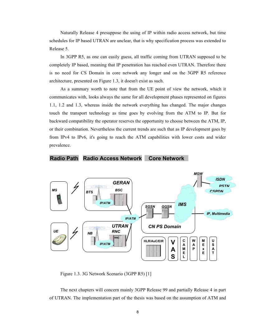
In 3GPP R5, as one can easily guess, all traffic coming from UTRAN supposed to be
completely IP based, meaning that IP penetration has reached even UTRAN. Therefore there
is no need for CS Domain in core network any longer and on the 3GPP R5 reference
architecture, presented on Figure 1.3, it doesn't exist as such.
As a summary worth to note that from the UE point of view the network, which it
communicates with, looks always the same for all development phases represented on figures
1.1, 1.2 and 1.3, whereas inside the network everything has changed. The major changes
touch the transport technology as time goes by evolving from the ATM to IP. But for
backward compatibility the operator reserves the opportunity to choose between the ATM, IP,
or their combination. Nevertheless the current trends are such that as IP development goes by
from IPv4 to IPv6, it's going to reach the ATM capabilities with lower costs and wider
prevalence.
Figure 1.3. 3G Network Scenario (3GPP R5) [1]
The next chapters will concern mainly 3GPP Release 99 and partially Release 4 in part
of UTRAN. The implementation part of the thesis was based on the assumption of ATM and
CSPDN
ISDN
PSTN
VAS
C A M E L
W A P
M E x E
U S A T
RNC
IP, Multimedia
MS BTS BSC
MGW
HLR/AuC/EIR
UE NB RNC
SGSN GGSN
GERAN
UTRAN
Radio Path Radio Access Network Core Network
CN PS Domain
IMS
IP/ATM
IP/ATM
IP/ATM

9
ATM Adaptation Layers being used as a transport technology within UTRAN, thus we will
not concern IP issues, except Chapter 5 where as a conclusion the future of UTRAN transport
will be discussed.
1.2 Basic concepts in UMTS
This chapter describes basic concepts and elements of UMTS. Following the Figure 1.4,
where the general UMTS network architecture is presented, the UMTS system description in
this chapter is subdivided into three sections: WCDMA as a radio technology, Radio Access
Network and Core Network. WCDMA section gives the rough overview of the radio
technology and its basic elements. The special attention is paid to the description of Radio
Access Network as far as the rest of thesis is concentrated within this UMTS system part. And
finally the third section in this chapter in several words describes functionality of CN and its
elements.
Figure 1.4. UMTS system architecture
Legend:
UE: User Equipment NB: Node B RNC: Radio Network Controller 3G-SGSN: 3G Serving GPRS Support Node GGSN: Gateway GPRS Support Node SCP: Service Control Point
WMSC: Wideband Mobile Switching Center VLR: Visitor Location Register HLR: Home Location Register UTRAN: UMTS Terrestrial Radio Access Network GMSC Gateway MSC RNS: Radio Network Subsystem
X 25PSPDN
ISDNPSTN
CSPDN
RNC
Other Data NW
Internet
WMSC/VLR GMSC
HLR
UE
NB
3G-SGSN GGSN
Radio Path UTRAN CN
NB
RNC
NB
NB
UE
UE
SCP
Uu Iub
Iur
Iu
MAP
Gs
Gn
RNS
RNS
10
1.2.1 WCDMA Radio Interface
Radio interface technology has always been a subject of intensive research aiming to
achieve the most efficient utilization of radio resources that are in one way or another limited.
The choice of radio interface is the very crucial for overall functionality of the system since it
determines the capacity of mobile radio network. The 3G systems impose high requirements
on radio network capacity in order to serve greatly increased user traffic.
3GPP adopted several radio technologies for 3G mobile systems. In one way or another
all the technologies support the possibility to adapt the bandwidth on demand and provide
variable user data rates up to 2 Mbit/s. Some systems use Code Division Multiple Access
(CDMA), whereas others are variations of Time Division Multiple Access (TDMA).
The UMTS system employs new radio technology considered as a "revolutionary" part
of UMTS, Wideband Code Division Multiple Access (WCDMA). So why it is Code Division
and why it is Wideband? These questions are setteled in this chapter.
For better understanding of the Code Division Multiple Access technology we should
take a breif look at its alternatives, namely TDMA and FDMA (Frequency Division Multiple
Access).
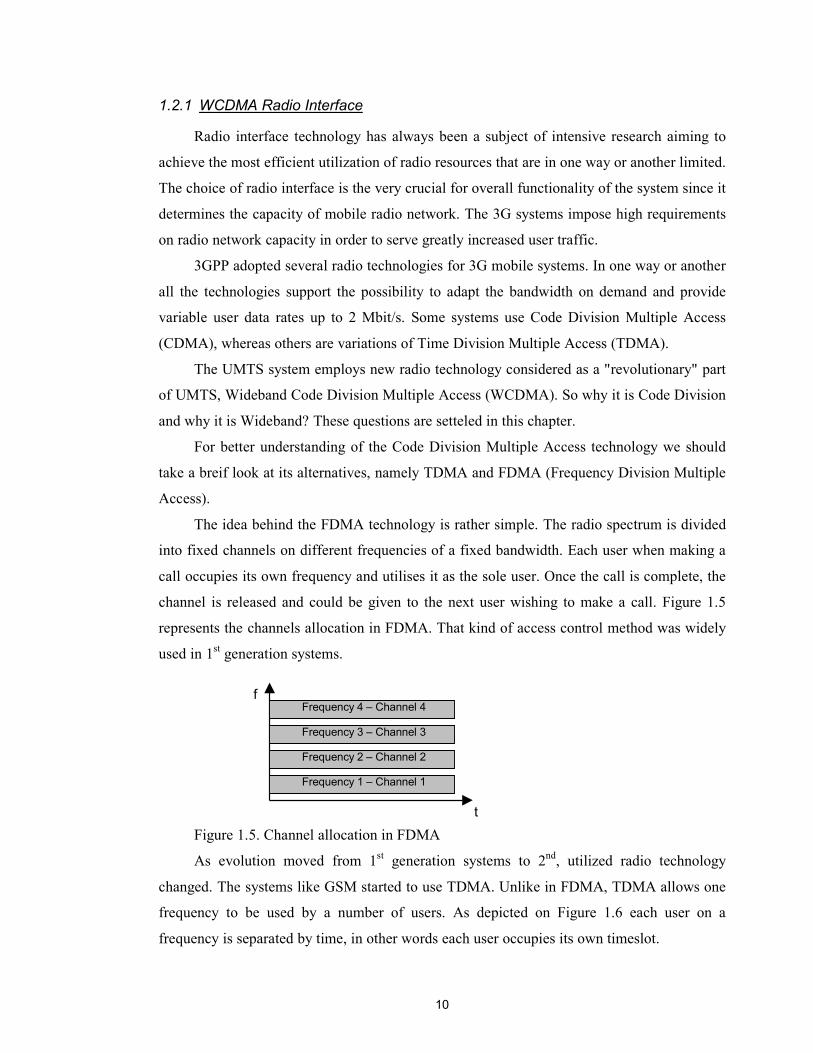
The idea behind the FDMA technology is rather simple. The radio spectrum is divided
into fixed channels on different frequencies of a fixed bandwidth. Each user when making a
call occupies its own frequency and utilises it as the sole user. Once the call is complete, the
channel is released and could be given to the next user wishing to make a call. Figure 1.5
represents the channels allocation in FDMA. That kind of access control method was widely
used in 1st generation systems.
Figure 1.5. Channel allocation in FDMA
As evolution moved from 1st generation systems to 2nd, utilized radio technology
changed. The systems like GSM started to use TDMA. Unlike in FDMA, TDMA allows one
frequency to be used by a number of users. As depicted on Figure 1.6 each user on a
frequency is separated by time, in other words each user occupies its own timeslot.
Frequency 1 – Channel 1
Frequency 2 – Channel 2
Frequency 3 – Channel 3
Frequency 4 – Channel 4
t
f

11
Figure 1.6. Channel allocation in TDMA&FDMA
As opposed to both FDMA and TDMA in the case of CDMA we have the solution
where users share the same frequency and time, but are separated by codes. When a mobile
terminal is listening to many base stations it can easily discriminate between them since each
cell has its unique code. Similar, when a base station is listening to mobile stations, it can
distinguish different subscribers using a unique code. In such a way applying certain code to
the radio spectrum one can detect particular signal which is of interest while the rest of
uninteresting signals will be considered as a background noise. Therefore each channel in
WCDMA can carry several users having variable bandwidth separated by a code. This is
depicted on the Figure 1.7.
Figure 1.7 CDMA, channels occupy the same frequency and time.
The code used for separation purposes in CDMA is basically referred to as a Spreading
Code. This code is allocated for each user based on the QoS requirements, since it implicitly
determines the bit rate at which the actual user data will be transmitted. In fact the Spreading
Code is constituted by the multiplication of two different codes, called Channelisation Code
and Scrambling Code. Their use is presented in the following Table 1.2.
F1 – Ch1
t
f
F2 – Ch1
F3 – Ch1
F4 – Ch1
F1 – Ch2
F2 – Ch2
F3 – Ch2
F4 – Ch2
F1 – Ch3
F2 – Ch3
F3 – Ch3
F4 – Ch3
t
f

12
Channelisation Code Scrambling Code Usage Uplink: Separation of
physical data and control channels from same terminal Downlink: Separation of downlink dedicated user channels
Uplink: Separation of terminals Downlink: Separation of sectors (cell)
Length Variable (dependent on user allocation)
Fixed
Number of Codes Depends on Spreading Factor Uplink: Several million Downlink: 512
Table 1.2. Properties of Channelisation and Scrambling Codes [2]
The basic idea in WCDMA is that the user information bits (referred to as Symbols) are
spread over the bandwidth by multiplying them with a higher bit rate pseudorandom bit
stream. The bits in the pseudorandom bit steam usually referred to as Chips and their
sequence represents Spreading Code. In that way in order to transmit information over the
radio transmission path the sending side performs the spreading operation by multiplying
these two signals and on the other side reciever performs the inverse operation called
despreading by multiplying transmitted signal with the same code, as it's shown on Figure
1.8.
Figure 1.8. Symbols and Chips [2]
The multiplier characterising how information is spread along the chip rate is called
Spreading Factor. In other words it defines how many chips are used per one symbol.
Mathematically it can be expressed as follows:
8...2,1,0,2 �� kwhereK k
1
1
1
1
1
-1
-1
-1
-1
-1 Data
Spreading Code
Spreading Code
Data
Uu (air) interface
Chip
Symbol
Chip
Symbol
Data x code

13
In WCDMA the code signal bit rate, i.e. chip rate, is fixed at 3.84 Mcps (million chips
per second). Thus by adjusting the Spreading Factor we can achieve variable actual data bit
rate. For example in Figure 1.8 Spreading Factor is equal to 4, hence the user data bit rate is
3.84/4 = 0.96 Msps (million symbols per second).
The number 3.84 besides the chip rate defines the effictive bandwidth for WCDMA
(with guard bands the required bandwidth is 5 MHz). This explains why WCDMA has the
prefix Wide. The Wide in WCDMA has derived from the fact that the European and
Japanese 3G systems use a wider bandwidth than their American counterparts.
It is nesessary to note that WCDMA, specified by 3GPP, has two operational modes:
FDD and TDD. They are defined as follows:
�� Frequency Division Duplex (FDD): uplink (the transmission in direction from the
mobile terminal towards the base station) and downlink (the transmission in
direction from the base station towards the mobile terminal) use two different
carriers located in a separated frequency bands.
�� Time Division Duplex (TDD): uplink and downlink transmissions use the same
carrier but occupy different timeslots. The information is transmitted in turn on the
uplink or downlink.
All the information presented in the rest part of the thesis is based upon the UMTS-FDD
implementation, as far as this is the first mode that will be implemented for UMTS, support
for TDD will be added at a later stage.
There is also one issue to cover in this section that is essential for further reading in the
next chapters, the introduction of UMTS channel concept. This is done in the folloing
subsection.
1.2.1.1 WCDMA channels
When user wishes to make a connection to the radio access network or vice versa,
WCDMA radio access allocates radio and transport resources for that connection. The
allocated resources are handled by the term "channel". Channel can be viewed as a logical
representation of the information flow between two communicating points. If we are talking
about layered architecture of protocol software there can be different types of channels
constituted by different layers with different levels of abstraction. In the case of UMTS, as it
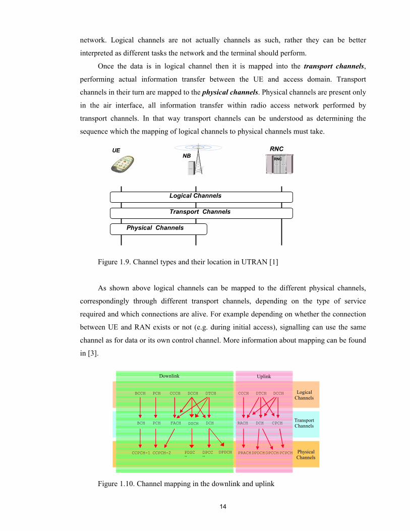
is shown on the Figure 1.9 there are three layers of channels.
The first type of channels is known as the logical channels, they are located on the
highest level and used for applications and signalling procedures to communicate with the
14
network. Logical channels are not actually channels as such, rather they can be better
interpreted as different tasks the network and the terminal should perform.
Once the data is in logical channel then it is mapped into the transport channels,
performing actual information transfer between the UE and access domain. Transport
channels in their turn are mapped to the physical channels. Physical channels are present only
in the air interface, all information transfer within radio access network performed by
transport channels. In that way transport channels can be understood as determining the
sequence which the mapping of logical channels to physical channels must take.
Figure 1.9. Channel types and their location in UTRAN [1]
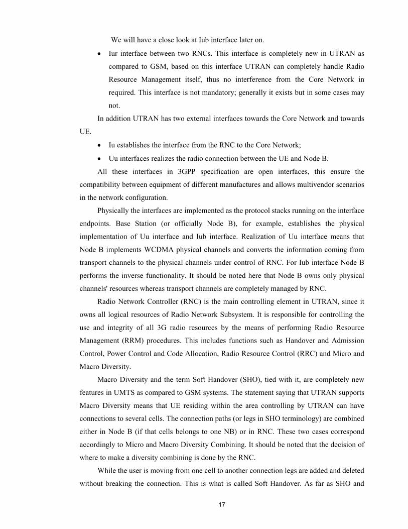
As shown above logical channels can be mapped to the different physical channels,
correspondingly through different transport channels, depending on the type of service
required and which connections are alive. For example depending on whether the connection
between UE and RAN exists or not (e.g. during initial access), signalling can use the same
channel as for data or its own control channel. More information about mapping can be found
in [3].
Figure 1.10. Channel mapping in the downlink and uplink
RNCNBRNCUE
Logical Channels
Transport Channels
Physical Channels
Logical Channels
Transport Channels
Physical Channels
Downlink Uplink
BCCH PCH CCCH DCCH DTCH CCCH DTCH DCCH
BCH PCH FACH DCH DCHRACH CPCH
CCPCH-1 CCPCH-2 DPCCH
DPDCH PRACHDPDCHDPCCHPCPCH PDSCH
DSCH

15
Further we will mainly concern transport channels since their management, allocation
and deallocation is the subject of transport resource management. Following gives the rough
overview of the transport channels existing in the UTRAN.
According to nature of transferred information the transport channels can be split into
two groups: common transport channels shared by several terminals, and dedicated transport
channels used for connection of one terminal with the network. Each group includes different
channels in uplink and downlink directions.
The Transport Channels carrying the information flows in downlink direction are:
�� Broadcast Channel (BCH). This common channel contains information about the
radio environment, e.g. code values used in the current and neighboring cells,
allowed power levels, etc.
�� Paging Channel (PCH). This common channel is used by the network to find out
the exact location of the particular UE for example when the network needs to setup
a connection with that UE. All terminal continuously listen to the PCH to pick up
the paging request for them.
�� Forward Access Channel (FACH). This channel comprises Logical Common
Control Channel, Dedicated Control Channel and Dedicated Traffic Channel, thus
may carry common information for all UE residing in the cell as well as dedicated
control and payload information.
�� Downlink Shared Channel (DSCH). This common channel encapsulates data
coming from Logical DCCH and/or DTCH and is used for asymmetric connections
where the amount of information in downlink is so small that there is no need for
allocation of dedicated channel. It can be shared by the several users and quite
similar to FACH.
�� Dedicated Channel (DCH). This is the only dedicated channel. It contains
information coming from both Logical Dedicated Traffic Channels (DTCH) and
Dedicated Control Channel (DCCH), i.e. the actual user traffic. Moreover it can
carry the information from several DTCHs depending on the case. For instance user
may have several connections for different services (e.g. voice and video call). Each
service requires individual DTCH, however all of them use the same DCH. It should
be noted that DCH is the dynamically allocated resource, it can be setup on demand
for one user and then released, whereas common channels basically exist
permanently.

16
The traffic in uplink direction is much smaller, thus it requires less transport and
physical resources. There are only three Transport Channels available in uplink:
�� Random Access Channel (RACH). This channel used by the UE to send the initial
access information when it wants to setup a connection with the network. Also
mobile terminal responds to the paging request on this channel. Besides this, RACH
can contain the small portion of dedicated information coming from Logical DTCH
and DCCH instead of allocation new DCH.
�� Dedicated Channel (DCH). It carries the same information as a DCH in the
downlink direction.
�� Common Packet Channel (CPCH). It carries small amounts of user packets if the
common resources are used for this purpose.
In conclusion it should be noted that some transport channels are optional (e.g. DSCH),
whereas some are mandatory. Channels such as FACH, RACH and PCH play the essential
role in the overall system functionality.
Now we are familiar enough with the basic radio and transport concepts of WCDMA
and can proceed further towards the UMTS system element that manages all that resources,
UMTS Terrestrial Radio Access Network (UTRAN).
1.2.2 UMTS Terrestrial Radio Access Network
As presented on the Figure 1.11 UTRAN
has two main elements: Node B and Radio
Network Controller (RNC). One RNC together
with Node Bs belonged to it constitutes Radio
Network Subsystem, the least structural element
in UTRAN. Each RNC is responsible for the set
of cells that can be covered by one NB or several
NBs (one NB per cell).
There are two internal interfaces within the
UTRAN:
�� Iub interface located within RNS
between RNC and NB.
Figure 1.11. Radio Access Network
RNCNB
RNC
NB
NB
UE
Uu Iub
Iur
RNS
RNS
Iu
17
We will have a close look at Iub interface later on.
�� Iur interface between two RNCs. This interface is completely new in UTRAN as
compared to GSM, based on this interface UTRAN can completely handle Radio
Resource Management itself, thus no interference from the Core Network in
required. This interface is not mandatory; generally it exists but in some cases may
not.
In addition UTRAN has two external interfaces towards the Core Network and towards
UE.
�� Iu establishes the interface from the RNC to the Core Network;
�� Uu interfaces realizes the radio connection between the UE and Node B.
All these interfaces in 3GPP specification are open interfaces, this ensure the
compatibility between equipment of different manufactures and allows multivendor scenarios
in the network configuration.
Physically the interfaces are implemented as the protocol stacks running on the interface
endpoints. Base Station (or officially Node B), for example, establishes the physical
implementation of Uu interface and Iub interface. Realization of Uu interface means that
Node B implements WCDMA physical channels and converts the information coming from
transport channels to the physical channels under control of RNC. For Iub interface Node B
performs the inverse functionality. It should be noted here that Node B owns only physical
channels' resources whereas transport channels are completely managed by RNC.
Radio Network Controller (RNC) is the main controlling element in UTRAN, since it
owns all logical resources of Radio Network Subsystem. It is responsible for controlling the
use and integrity of all 3G radio resources by the means of performing Radio Resource
Management (RRM) procedures. This includes functions such as Handover and Admission
Control, Power Control and Code Allocation, Radio Resource Control (RRC) and Micro and
Macro Diversity.
Macro Diversity and the term Soft Handover (SHO), tied with it, are completely new
features in UMTS as compared to GSM systems. The statement saying that UTRAN supports
Macro Diversity means that UE residing within the area controlling by UTRAN can have
connections to several cells. The connection paths (or legs in SHO terminology) are combined
either in Node B (if that cells belongs to one NB) or in RNC. These two cases correspond
accordingly to Micro and Macro Diversity Combining. It should be noted that the decision of
where to make a diversity combining is done by the RNC.
While the user is moving from one cell to another connection legs are added and deleted
without breaking the connection. This is what is called Soft Handover. As far as SHO and
18
Macro Diversity are not limited within one RNS they would not be possible without addition
of new interface between two RNCs, Iur interface.
Supporting Macro Diversity and SHO features over the Iur interface RNC may act in
the three logical roles. The RNC having one Node B under its supervision acts as a
Controlling RNC. In this role RNC is in charge of the load and congestion control in the cells
belonging to that Node B and also fulfil configuration and fault management over the Iub
interface. From UE point of view RNC may play two logical roles. First, when the UE
initiates the connection, the RNC that first serve it becomes the Serving RNC (SRNC).
Serving RNC owns all logical resources belonging to the user connection. Thus there can be
only one SRNC per UE. As UE moves around the coverage area, due to the multi-path
propagation property of radio signal, it may happen so that UE establishes the connection
with several Node Bs belonging to different RNCs. That newly equipped RNCs are called
Drifting RNCs. When all the branches go through one Drifting RNC UTRAN can perform the
Serving RNC Relocation procedure. Serving RNC is the place where the Macro Diversity as
such is executed.
1.2.2.1 Transport Technology in UTRAN
The transport technology in UTRAN has always been one of the hot topics in UMTS
standardization. There are many requirements imposed on it. First of all it should support both
circuit and packet switched traffic and on the other hand keep up the efficient utilization of
the WCDMA radio channels, i.e. guarantee QoS and support for different bit rate classes.
The 3GPP has chosen the Asynchronous Transfer Mode (ATM) as the most closely
corresponding to the imposed requirements transport technology. It combines benefits of both
circuit switching (small and deterministic transmission delay, guaranteed transmission
capacity) and packet switching (flexibility and efficiency for intermitten traffic). This is
achieved by using the small, fixed packets, called cells, as transfer units. That is why ATM is
called a cell switching technology. Each cell is of the length of 53 octets (bytes), containing 5-
byte-long header (address information) and 48-byte-long payload (transmitted information).
ATM is known as a connection oriented protocol. Therefore before sending an
information between two nodes one has to establish a connection (or Virtual Channel in ATM
terminology). There can be two types of connection, Virtual Channel as such and Virtual Path
(VP) which is the bundle of VCs. There can be thousands of VC within one VP, for instance
in transmission of multimedia information, that requires several VCs simultaneously, one VC
per each multimedia component. In more details ATM is described later on in the next
chapters.
19
In theory ATM layer consists of simple transport media and is suitable for transmission
purposes as such. But in practise the ATM layer must be adapted to the higher protocol layers
in order to enable the most efficient utilisation of transport resources, regarding to the type of
traffic produced by higher level protocols. UTRAN employes two types of ATM Adaptation
Layers (AAL), namely AAL Type 2 (AAL2) and AAL Type 5 (AAL5). The AAL2 is used
within the User Plane as the most appropriate for nature of traffic produced by Frame
Protocols (e.g. voice and video). And AAL5 is used within the Control Plane as an
underlaying transport layer for application protocols, i.e. for transmission of signalling data.
The ATM Adaptation Layers will also be described in more datails in the later chapters.
1.2.3 Core Network
Core Network architecture is a very wide and complicated topic to describe since it
comprises the essential logical and computational resources in the 3G system. It needs the
separate study to expose all its functionality and structure. Since this thesis concentrated only
within the Radio Access Network, the CN is out of our interest, therefore this section presents
its very brief overview, merely in order to provide reader with the complete picture of UMTS
system.
The Core Network performs all the functionality tied with switching (in Circuit
Switched Domain) and routing (in Packet Switched Domain). In the other words it enables
service provision to the UMTS subscribers.
UMTS supports both types of services, circuit- and packet-switched. This constitutes
basic CN architecture logically divided into two parts, which are Circuit Switched Domain
(CS Domain) and Packet Switched Domain (PS Domain). Its general view is represented on
Figure 1.12.
CS Domain is used for handling circuit-switched connections, e.g. for voice and
streaming video. Such kind of connections once being set up remain active during the whole
communication time. They can provide constant data flow with deterministic variable bit rate,
therefore enabling real-time traffic.
On the other hand PS Domain handles packet-switched traffic, requiring no constant
link between end-points to be set up. The data in here is divided into packets, which are
transferred through packet-switched network to the destination. Data flow in PS Domain has
intermittent character and primary contains non-realtime data and services (but also can be

20
real-time traffic), in such a way representing always-on type of connections that work on the
background.
Figure 1.12. Generalized CN architecture (3GPP R99)
As it can be easily seen from the Figure 1.12, apart from CS and PS Domains the CN
contains the set of register nodes – the databases storing subscribers' profiles, data needed for
connection establishment and security activities.
The following is the brief description of the CN main elements.
Circuit Switched Domain
It has two basic elements, Mobile Switching Center (MSC) combined with Visitor
Location Register (VLR) and Gateway Mobile Switching Center (GMSC). These two
elements have different functionality but physically may be located in a one node.
�� MSC: this element is responsible for call controlling activities, such as connection
establishment, connection release and switching the established connections
between two end users. It also performs activities related to mobility management of
UE, such as location update, location registration, paging and security issues.
Legend:
SGSN: Serving GPRS Support Node GGSN: Gateway GPRS Support Node CS: Circuit Swiched GMSC Gateway MSC PS: Packet Switched
MSC: Mobile Switching Center VLR: Visitor Location Register HLR: Home Location Register AuC: Authentication Center EIR: Equipment Identity Register
External Networks
MSC/VLR3G 3G GMSC
HLR/AuC/EIR
SGSN GGSN
CN CS Domain
CN PS Domain
Registers Access Networks
CN
21
�� GMSC: this node is in charge of all incoming and outgoing connections from and to
other networks, such as PSTN, ISDN or other PLMN.
Packet Switched Domain
The PS Domain also contains two basic elements: Serving GPRS Support Node (SGSN)
and Gateway GPRS Support Node (GGSN).
�� SGSN: this node has almost the same responsibility as MSC in CS Domain, but in
respect to packet-switched connections.
�� GGSN: this element establishes and maintains the packet-switched connections
towards other PS networks, such as Internet.
CN Registers
Registers are used by both PS and CS Domains, storing different kind of information
about subscribers.
�� Home Location Register (HLR): it is the most important database containing
permanent subscribers' information. It stores subscriber's profile and information
about its current location that is queried by GMSC or GGSN.
�� Visitor Location Register (VLR): this database temporary stores information about
the subscribers located in the service area of MSC. When subscriber roam into the
service area of the MSC its information is copied from the HLR to the VLR
associated with that MSC, so that MSC will have all necessary information needed
for connection and mobility management of served user.
�� Authentication Center (AuC): this database stores authentication and encryption
information needed during connection set-up phase to verify user's identity and
ensure the confidentiality of each call.
�� Equipment Identity Register (EIR): EIR database handles security information
related to the UE hardware. Such kind of information is needed for example to
prevent calls from stolen or defective terminals.
CN may also include a number of value added service elements, for example Short
Message Service Center (SMSC) and Voice Mail System (VMS). They are not included in
CN general architecture description since it is implementation specific issue.
1.3 Generic model of UTRAN interfaces
In this section we will introduce the operational environment which is in concern of our
problem domain, the general UTRAN protocol model.

22
There are four interfaces specified for UTRAN: Iu toward CN, Uu – radio interface, Iur
– between two RNC and Iub – between RNC and Node B, which is of our prime interest. All
the interfaces are open, meaning that 3GPP defines open specifications of the protocols that
physically implement the interface. The set of protocols defined for each interface is
organised in a stack and follows the general protocol model. Such model for UTRAN
interfaces is depicted on the Figure 1.13.
Figure 1.13 General Protocol Model for UTRAN interfaces [4]
The UTRAN protocol architecture follows the generic principles of OSI (Open System
Interconnection) reference model. In OSI model each communicating node is subdivided into
different functional layers. Each layer provides its services to the layer above and uses the
services from the layer below. By the means of that on the logical level it can communicate
with its peer entity via messages called Protocol Data Units (PDU). There are totally seven
layers in the OSI model, but this doesn't mean that every protocol stack defined according to
open standards must also have seven layers, rather it can be mapped in to the arbitrary number
of OSI layers.
Following this principle the URTAN interface model is subdivided into two layers.
Besides layers separation vertically it is divided into two planes. Each layer and plane is
logically independent of each other, so that a protocol or a protocol stack can be changed
without affecting the other layers or planes.
Horizontally the interface structure separates all the UTRAN related functionality from
the terrestrial transport functionality into two layers: Radio Network Layer and Transport
Network Layer respectively.
ApplicationProtocol
Data Stream(s)
ALCAP(s)
Transport Network
Layer
Physical Layer
SignallingBearer(s)
Transport User
NetworkPlane
Control Plane User Plane
Transport User
Network Plane
Transport NetworkControl Plane
Radio Network
Layer
SignallingBearer(s)
Data Bearer(s)
23
Radio Network Layer comprises the protocols that are specially designed for the UMTS
system and the common task for them is to perform all the UTARN related functionality,
independently from the underlying transport technology. This layer takes care about the
management and use of radio access bearers across the set of UTRAN interfaces. In the terms
of interaction between Radio Network Layer and Transport Network Layer it can be said that
Radio Network Layer creates some information to be transported to the other node and passes
this information to the Transport Network Layer which performs the actual information
transferring over the physical media, regardless to the content of that information.
In that context Transport Network Layer can be viewed as a responsible for the
management and use of transport bearers, which in particular serve as a part of Radio Access
Bearer on the level of transport network in the UTRAN interface. This functionality includes
the signalling, establishment, maintenance and release of transport bearers. The name
Transport is used here in the same sense as its OSI meaning, i.e. to cover the set of protocols
allowing distributed nodes to communicate with each other through heterogeneous
internetwork. As distinct from Radio Network Layer, Transport Network Layer was designed
with the assumption that it may include all those protocols, which were selected from existing
protocol suits instead of having to design them specially for UMTS purposes.
For example, the current choice for the transport technology is ATM, whereas layered
topology of interface model allows to easily change transport in future to IP based, or any
other transport technology, by simply replacing the Transport Network Layer, while the Radio
Network Layer will remain intact.
In this section we have used term Radio Access Bearer, that was not defined previously.
In following paragraph the short definition of notion bearer in UMTS is given, since this term
will be used in the further statements.
From the end-user point of view the UMTS system mainly acts as an infrastructure
providing facilities, adequate bandwidth and quality of connection between end-users and
their applications. When the one end-user establishes a connection with another terminal or
service platform, this connection requires a lot of resources to be dedicated in order to transfer
the information flows across the UMTS network. In general all resources involved can be of
the different nature and belonging to different networks. Thus some accociation between that
resources is needed. Here comes the notion bearer that represents all the resources involved in
information transmission and association between them. Figure 1.14 shows the layered
architecture of UMTS bearers.

24
UMTSGateway
Node
UTRAN-CNEdge Node
ServingRadio
NetworkController
Node BUserEquipment
UMTS Bearer Service
Radio Access Bearer Service CN Bearer Service
Radio Bearer Service Iu Bearer service Backbone NetworkService
Radio Link Iub/Iur TransportBearer
Iu TransportBearer
CN TransportBearer
Uu Iub/Iur Iu Gn
Figure 1.14. UMTS bearer service architecture
The overall resources involved in information exchange between two end-users constite
the end-to-end bearer. As we go down across its layered architecture end-to-end bearer breaks
down into several components belonging to different UMTS subsystems, which in turn
consist of their constituent parts belonging to different interfaces. In such a way the Radio
Access Bearer (RAB) is all the UTRAN resources, which are dedicated to transport user
information for some particular user connection across itself, and it can be viewed as a
service, which UTRAN provides to CN and UE.
Now lets get back to the examination of general protocol model for UTRAN interfaces.
In addition to horizontal layerisation the architecture is divided into two planes: Control Plane
and User Plane. This is based on the one of the main principles borrowed from SS7 networks,
the clear separation of control (signalling) information and user traffic. One should realise that
any bearer whether it is end-to-end bearer or RAB or transport bearer is not a static one, but
rather it represents the dynamically allocated resources. Therefore in order to allocate that
resources, in other words to setup bearer, a lot of control information need to be exchanged.
Once being setup bearer may need to be reconfigurated and finally released, that also requires
exchange of control information. In telecommunication terminology such kind of exchange of
control information is called signalling. The signalling is conveyed by Application Protocols
resided in the Control Plane, whereas all user traffic traverse through User Plane.
In such a way the Control Plane embrace both radio and transport network layers and
consists of an Application Protocol and Signalling Bearers. The Application Protocols take
care about all signalling functionality in the UTRAN required for setting up and maintaining
Radio Access Bearers and Radio Links, which include setting up dedicated signalling and
Radio Path

25
user connections and exchanging other UTRAN-specific control information They use
generic bearer parameters to establish RABs. Since the signalling functions at each interface
differ there are different Application Protocols specified for each interface. They are RANAP
for Iu, RNSAP for Iur and NBAP for Iub interfaces. The latter will be described in more
details in the next chapters.
For transporting the signalling information between two Application Protocol entities
the Control Plane includes signalling bearers. They serve as permanent connections dedicated
only for transporting the Application Protocol messages. The signalling bearers are always set
up by Operation and Maintenance (O&M) actions during the installation or reconfiguration of
the network.
The UTRAN Control Plane protocols implement the client-server principle. Regarding
to Iub interface, which is of our prime interest, Node B takes the role of the server and RNC
behaves as a client requesting to perform some actions. In such a client-server based protocol
architecture the behavior of a server protocol entity is defined in terms of what kind of actions
it should perform when receiving a service request from its client.
Whereas Control Plane performs all control functionality, the actual user traffic, such as
coded voice or IP packets, is conveyed through the User Plane. The User Plane consists of
the Data Streams and Data Bearers. Data Steams are formed on the Radio Network Layer by
the frame protocols specified for each interface. The frame protocol is the common name for
user plane protocols, since their common property is to be responsible for efficient transfer of
user data frames. The Data Bearers perform the actual data transferring across the interface on
the Transport Network Layer.
In order to ensure an efficient and reliable transmissoin over the signalling or data
bearers they must be controlled and maintained on the level of Transport Network Layer. This
requires the introduction of Transport Network Control and User Planes.
From the Transport Network Layer point of view there is no difference in what kind of
information to transfer. As it was described earlier it does not somehow interpret the
information formed on the Radio Network Layer, thus this information does not affect on the
way it is transported. That is why the mapping between the control and user planes on the
Transport Network Layer and those on the Radio Network Layer, is not one to one. In general
the idea behind the user and control planes can be summarised as follows. The user plane
represents the overall resources dedicated to actual traffic transferring and the functionality
connected with it and the control plane represents the functionality tied with controlling and
maintaining that dedicated resources. From this point both Signalling and Data bearers in the
26
UMTS Control and User Planes forms the user plane on the Transport Network Layer, called
Transport Network User Plane.
The Transport Network User Plane is not homogenous in its structure as the user plane
on the Radio Network Layer, since it is assumed to carry two types of traffic conveyed by
signalling and data bearers. Signalling bearers, as it was mentioned earlier, are statically
allocated by O&M actions, thus they do not need any controlling elements. At the same time
data bearers are dynamically allocated ones and should be set up for each dedicated
connection. For that there is a Transport Network Control Plane located between Control
Plane and User Plane.
The Transport Network Control Plane is responsible for transport bearer management,
which includes the signalling, establishment, maintenance and release of transport bearers. It
contains the Access Link Control Application Part (ALCAP) protocol and signalling bearers
used to transport ALCAP's messages to its peer entity across the interface. Signalling bearers
here may be of the same type as those used by Application Protocols on the Control Plane.
ALCAP is the generic name for transport signalling protocols. It depends on the underlying
transport technology and can be one of the already standardised signalling protocols, for
example Q.2630.1 [5]. Above all ALCAP ensures the Radio Network Layer to be truly
independent from the underlying transport. It means that when Application Protocol needs to
set-up a bearer for User Plane, it provides the ALCAP with rather generic bearer parameters
that are not tied to the transport technology. All this enables seamless changing of the
transport technology if needed.
1.4 Protocol stack in UTRAN
In this thesis we concern both Radio Network and Transport Network Layers, since they
both are involved in the functions of transport resource management. From the overall UMTS
protocol interworking architecture perspective there is also the third layer called System
Network Layer. The protocols in this layer extend from UE across the UTRAN until the
transit network edge in the CN. Their responsibility is to ensure interworking on UMTS
communication service related aspects. Such protocols as CM (Connection Management) and
MM (Mobility Management) belong to that category, thus they left out of scope of this thesis,
and not presented on the figures below (although in reality they exist on the UE and CN side).

27
Figure 1.15. Control Plane protocol stack in UTRAN
Figure 1.15 represents the UTRAN protocol stack within the control plane, where Iu
interface represents IP option for signalling transport, and Figure 1.16 shows protocol stack
within the user plane. It should be noted that it's applicable only for packet-switched domain.
For circuit-switch domain Radio Network Layer remains intact, the only difference is in
Transport Network Layers used for Iu interface because of different nature of traffic in these
domains.
Figure 1.16. User Plane protocol stack in UTRAN (PS Domain only)
Futher on we will concentrate only on the Iub interface and protocols that physically
implement it. Detaled description of those protocols used in Iub interface will be presented in
the later chapters. Other interfaces and the protocols tied with them are out of scope of this
thesis, and therefore only their short decription is given here.
Radio Resource Control (RRC) protocol is the essential protocol in performing radio
resource management tasks. It is used to set-up, and maintain the dedicated Control and User
Planes radio specific connections between UE and RNC, i.e. the radio bearers, transport and
physical channels between UE and RNC. RRC protocol performs only on the control plane
data transfer, whereas on the user plane the convergence sublayer is needed. That
functionality performed by the Packet Data Convergence Protocol (PDCP) sublayer. It
MAC WCDMA L1
RLC RRC
RNC
MSC or SGSNUE
Transportlayers
NBAP
MACRLC
RRC RANAP RANAP
Iu
Node B
NBAP
MAC
WCDMA L1
RLC
Node BRRC
IubUu
AAL5ATM
Physical layer
AAL5ATMPhysical
layer
SCCP ATM or IP
Physical layer
SCCPATM or IP
Physical layer
MAC WCDMA L1
RLC PDCP
RNC
SGSNUE
Transportlayers
Iub FP
MACRLC
PDCP Iu FP
Node B
Iub FP
MAC WCDMA L1
RLC
IubUu
AAL2ATM
Physical layer
AAL2ATMPhysical
layer
GTP-U UDP/IP
Physical layer
Iu FP
GTP-UUDP/IP
Physical layer
Iu

28
makes the UMTS radio interface applicable to carry IP data packets. Both RRC and PDCP
protocols use the bearer service provided by the RLC sublayer to transport the signalling and
data messages between their protocol entities.
Radio Link Control (RLC) protocol performs the regular data link layer functionality
(according to OSI model). It is in charge of flow control procedures, segmentation and
reassembly of higher-levels protocol messages and the reliable transmission of data. The
operational environment of RLC depends on the plane discussed. In case of the user plane the
RLC is used by the PDCP protocol, and in the case of control plane it's used by the RRC
protocol.
Medium Access Control (MAC) protocol has the overall responsibility for controlling
the communications over the WCDMA transport channels provided by the physical layer. As
its service MAC provide a set of logical channels to the higher level protocol, i.e. RLC.
Node B Application Part (NBAP) protocol is used to maintain control plane signalling
over the Iub interface, i.e providing RNC with the means for controlling over Node B. On the
underlying transport network layer it uses ATM together with the AAL5 to transport
signalling messages over the interface. This application protocol, as well as its transport, will
be decribed in detail in later chapters.
Radio Network Subsystem Application Part (RNSAP) as well as NBAP is
application protocol, but it performs its control over the Iur interface. Unlike the NBAP,
RNSAP is a symmetric protocol, thus running by two RNCs, one of which takes the role of
SRNC and another acts as DRNC.
Radio Access Network Application Part (RANAP) is the third application protocol in
UTRAN. It runs on the top of Iu signalling transport layer. One of RANAP peer entity is
resided at RNC while another at the MSC or SGSN. RANAP is used to set-up and maintain
Control Plane and User Plane connections across Iu interface thus handling communication
between UTRAN and CN.
On the transport network layer Iu interface employes two alternatives: GPRS
Tunneling Protocol (GTP-U) and Signalling Connection Control Part (SCCP)
correspondingly for User and Control Planes. GTP-U is a transport network protocol
belonging to the packet switched domain in the UMTS. It provides the connectionless data
transfer. At the same time SCCP is the connection-oriented protocol (but can be also in a
connectionless mode) supporting control plane data transfer. Above all it is responsible for
maintaning the harmonization between the IP and ATM transport options.
29
This section concludes the overall UTRAN description as a part of UMTS system. The
rest of the thesis will be concentrated only on the Iub interface, as the sole interface located
within the Radio Network Subsystem.
30
2. Iub INTERFACE
In this chapter we will have a closer look at the Iub interface, facilitating the inter-
connection between the Radio Network Controller and the Node B.
The introduction of the Iub interface followed two main capabilities to be facilitated.
The first is the radio application related signalling. This allows the RNC and the Node B to
negotiate about the radio resources, for example to add or delete cells, controlled by Node B
to support communication of the dedicated connection between the UE and Serving RNC.
This cathegory also includes the information used to control the broadcast channel and the
common information to be transported on this channel.
And the second is the provision of the means for transport of uplink and downlink
WCDMA transport channels' frames between RNC and Node B. This is done by Iub Data
Streams. Each of them conforms to the the data carried on the corresponding transport
channel. The following is the set of Data Streams provided by the Iub interface: Iub DCH data
stream, correponding to one bi-directional transport channel; Iub RACH data stream; Iub
CPCH data stream [in FDD mode]; Iub FACH data stream; Iub DSCH data stream; Iub
USCH data stream [in TDD mode]; Iub PCH data stream. For description of each transport
channel, corresponding to Data Streams enumerated above, please refer to Section 1.2.1.1.
Every one Iub Data Stream is carried on one transport bearer, resided within Transport
Network Layer. Thus it is the responsibility of Iub signalling protocols to ensure the
establishment of a transport bearer over Iub interface for each Iub Data Stream.
This responsibility is covered by one of the Iub functions called Management of Iub
Transport Resources, which is the main problem domain in this thesis. The Iub Transport
Resource Management is conducted by RNC and physically realized together by two
siganalling protocols, NBAP in the Radio Network Layer and ALCAP in the Transport
Network Layer. These two protocols will be decribed in details later on . In rough review the
Transport Resource Management from the RNC point of view is concluded in assuring the set
up, maintenance and release of the underlying transport resources. If we are talking about the
ATM together with its Adaptaition Layers used as a transport technology, the transport
resources to be controlled over Iub interface are represented by the AAL2 connections
between RNC and Node B.
Besides the Transport Resouce Management Iub interface performs plenty of other
functions such as [6]:

31
�� Logical O&M of Node B. It comprises the signalling associated with the control of
logical resources (channels, cells,…) owned by RNC but physically implemented in
the Node B. This is mainly performed by the NBAP protocol procedures.
�� System Information Management. Such kind of information can be provided by
Controlling RNC in order to Node B update related system information. At the same
time Node B can autonomously create and update certain Node B related system
information on request from CRNC.
�� Traffic Management of Common Channels. The common channels are controlled
from the RNC. This is typically the control of RACH, CPCH and FACH channels,
the information that is broadcast on the Broadcast Control Channel, and the control
and request for sending information on the Paging Channels.
�� Traffic Management of Dedicated Channels. This functions are related to the
activation of logical resources (e.g. Radio Links, Iub ports), and the connection of
these various resources together.
�� Timing and Synchronisation Management. The processing of control and user plane
information needs to be synchronized in different network elements. Iub interface
supports the following synchronization types: Transport Channel (Frame)
Synchronization, Node B – RNC node Synchronization and Inter Node B node
Synchronization.
The enumerated functions include both signalling and user information transferring thus
employ control plane protocols as well as protocols in the user plane. The following section
gives the introduction of the protocol stack of the Iub interface.
2.1 Protocol stack of the Iub interface
The complete protocol structure of the Iub interface is shown, with the general triple
plane notation, in Figure 2.1. The Radio Network Layer defines the procedures related to the
operation of Node B and the Transport Network Layer defines the procedures for establishing
and releasing physical connections between Node B and the RNC.
Radio Network Layer within the user plane consists of the set of Frame Protocols (FP)
each for the corresponding transport channel. They define the structure of the frames and the
basic inband control procedures for each type of transport channel such as the Dedicated
Channel (DCH FP) and others. The structure of the Frame Protocols will be described in more
details in later chapters.
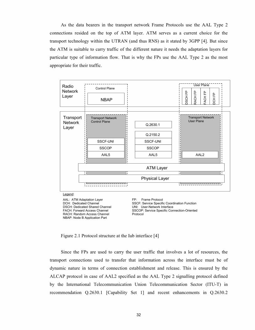
32
As the data bearers in the transport network Frame Protocols use the AAL Type 2
connections resided on the top of ATM layer. ATM serves as a current choice for the
transport technology within the UTRAN (and thus RNS) as it stated by 3GPP [4]. But since
the ATM is suitable to carry traffic of the different nature it needs the adaptation layers for
particular type of information flow. That is why the FPs use the AAL Type 2 as the most
appropriate for their traffic.
Figure 2.1 Protocol structure at the Iub interface [4]
Since the FPs are used to carry the user traffic that involves a lot of resources, the
transport connections used to transfer that information across the interface must be of
dynamic nature in terms of connection establishment and release. This is ensured by the
ALCAP protocol in case of AAL2 specified as the AAL Type 2 signalling protocol defined
by the International Telecommunication Union Telecommunication Sector (ITU-T) in
recommendation Q.2630.1 [Capability Set 1] and recent enhancements in Q.2630.2
Physical Layer
ATM Layer
AAL2 AAL5 AAL5
SSCOP
SSCF-UNI
SSCOP
SSCF-UNI
Q.2150.2
Q.2630.1
Transport NetworkUser Plane
NBAP
User PlaneControl Plane
Transport Network Layer
DSC
H F
P
RAC
H F
P
DC
H F
P
FAC
H F
P
Transport NetworkControl Plane
Radio Network Layer
Legend:
AAL: ATM Adaptation Layer DCH: Dedicated Channel DSCH: Dedicated Shared Channel FACH: Forward Access Channel RACH: Random Access Channel NBAP: Node B Application Part
FP: Frame Protocol SSCF: Service Specific Coordination Function UNI: User-Network Interface SSCOP: Service Specific Connection-Oriented Protocol
33
[Capability Set 2]. We will have a closer look at the transport network layer later on in this
chapter.
The protocol of the Radio Network Control plane is the NBAP. It allows Node B and
RNC to negotiate about the use of radio resources. This includes for example addition and
deletion of cells, the management of soft and softer handover (by the means of radio link
setup, addition and deletion), and the control of transmission power and addmission. Above
all NBAP also commands the ALCAP to setup or release transport bearer when needed, thus
participating in transport resource management. NBAP protocol will also be described
separately in the next chapter.
From the Transport Network Layer point of view the radio network layer protocols are
completely transparent, thus the NBAP signalling is just another type of user traffic than FP
traffic that has to transported through Transport Network User Plane by using AAL Type 5,
that seems to be the most appropriate for the signalling information.
The one of the general principles for the specification of the Iub interface, as stated by
3GPP [6], says that the Iub should be based on the logical model of Node B. Therefore in
order to provide the reader with the complete insight to the Iub interface, and aslo for the
further purposes, it is necessary to briefly introduce the logical model of the Node B. This
issue is settled in the next section.
2.2 Logical model of the Node B
In order to ensure the independence from the physical Node B implementations of
different manufacturers that can be in one way or another vendor specific, 3GPP defines the
general logical model of Node B. Such a model represents the physical resources of Node B
hidden behind the logical entities, that are only visible from the RNC side. Controlling RNC
serves as a sole owner of the Node B's logical resources, and since they are generalized the
RNC does not care about the physical architecture of Node B it communicates with, rather it
deals with its logical entities. This guarantees that the RNC of one manufacturer is able to
command the Node B of another.
The Figure 2.2 represents the logical model of Node B as it is seen from the Controlling
RNC. All logical resources can be classified in two different ways.
First of all Node B consists of common and dedicated logical resources. The common
logical resources can be used by all UEs resided in the service area of particular Node B, for
example for initial access or in order to obtain the information about the radio environment in
the particular cell. Such kind of logical resources are represented by Common Transport

34
Channels with their attributes. They all have been described in the section 1.2.1.1. The
configuration of each Common Transport Channel is performed on request from CRNC using
common and logical O&M NBAP procedures. In the logical model Common Transport
Channels are accociated with the corresponding data ports. This is valid for FACH, RACH,
PCH, CPCH [FDD] and DSCH (which has also association with Node B Communication
Context), but not applicable for BCH that is carried directly on the Common Control Port
(Node B Control Port).
Each Common Transport Channel has the set of its attributes that basically includes the
type of the channel, data port associated with it and physical parameters.
Figure 2.2 Logical model of Node B [6]
At the same time the dedicated resources are identified by the Node B Communication
Contexts. A Nobe B Communication Context corresponds to all the dedicated resources that
are necessary for establishment and maintenance of user connection in dedicated mode using
dedicated and/or shared channels as restricted to a given Node B.
Since one Node B supports numerous user connections, there are a number of Node B
Communication Contexts inside a given Node B, one per connection. Each Node B
Communication Context contains one or more DCHs and/or DSCHs that are accociated with
their data ports. One given dedicated channel corresponds to one data port, except the case of
coordinated DCHs that are multiplexed into the same DCH data port.
As well as Common Transport Channels the Node B Communication Contexts have
their attributes basically consisting of:
�� the list of Cells where dedicated resources are used;
Node B
...
Node B Communication Contexts, with attributes
Common Transport Channels, with attributes
Iub RACH Data port
Iub FACH Data port
Iub PCH Data port
Traffic termination point
Iub DCH Data port
Iub DSCH Data port
Traffic termination point
Iub DCH Data port
Iub DSCH Data port
Controlling RNC
Iub CPCH Data port
CommunicationControl
Port
CommunicationControl
Port
Node B Control
Port
Cell Cell Cell Cell Cell Cell

35
�� the list of DCHs and DSCHs with the associated data ports, which are mapped to the
dedicated physical resources for that Node B Communication Context;
�� the complete transport channel characteristics for each DCH and DSCH;
�� physical layer parameters.
For controlling both dedicated and common resources Node B logical model provides
for a common control port (common signalling link) and a set of dedicated control ports
(dedicated signalling links) one per traffic termination point.
From the other hand, considering the Iub interface separation on the transport and
network layers, the Node B logical model may be viewed as compising two types of logical
resources: Radio Network Logical Resources and Transport Network Logical Resources. In
two following subsections we will merely enumerate Radio Network Logical Resources and
breafly review them, since they are not the subject of Transport Resource Management, and
take a close look at the Transport Network Logical Resources that are of our prime interest.
2.2.1 Radio Network Logical Resources
To run the radio network the CRNC needs both common and dedicated resources in the
Node B. The CRNC is the only one who manages radio network resources in the Node B, that
is it can order the Node B to configure, reconfigure and delete these resources. However, if
Node B cannot fully support the requested configuration because of lack of resources or
broken equipment it can indicate the availability of common resources. Therefore each
common resource has an operational state that can be one of the following: enabled (meaning
that the resource can be used by RNC), disabled (meaning that the resource cannot be used by
RNC) and not existing (meaning that the resource doesn't exist in Node B). The state
transition is triggered by the NBAP common procedures.
The Node B Radio Network Resources controlled by CRNC are the Cell, common and
dedicated physical and transport channels.
The Cell is the logical entity of the highest level of abstraction. It comprises all the
logical radio resources within the given geographical area. All common transport and physical
channels within given Cell belong to that Cell. The dedicated channels do not belong to any
Cell as such since they do not exist permanently, rather they belong to the particular UE
connection, however if any of Iub transport bearers for dedicated or common transport
channels exist when the Cell is deleted, those channels must be also deleted (common
channels triggered to the not existing state) and the Node B must initiate the release of those
transport bearers.
36
In general one Node B may support one or more Cells to cover the specific area by
using the directional beams.
One Cell can posses one or more common physical and transport channels, depending
on those type, whereas all common physical and transport channel can belong only to one
Cell.
2.2.2 Transport Network Logical Resources
As claimed by the principle of separation between Radio Network and Transport
Network Layers the Transport Network resources are used as a transport of the traffic
produced by the higher layer. From the Node B logical model perspective Transport Network
Logical Resources are represented by the traffic ports. Each port is associated with one or
more (in case of DCHs) transport channels and performs the actual mapping of the given
channel (or set of channels) to the transport bearer. Traffic ports are subdivided on the control
ports (signalling links), carrying signalling information and data ports (data links) for the
actual data traffic.
Therefore the Transport Network Logical Resources are:
�� Node B Control Port
�� Communication Control Ports
�� Traffic Termination Points
�� Data ports corresponding to each type of transport channels
Following is the brief description of each logical entity.
The Node B Control Port (the same as Common Control Port) is used to exchange the
NBAP signalling information for the logical O&M of Node B. Through this control port RNC
commands Node B to create the Node B Communication Contexts for dedicated UE
connections, to configure the common transport channels that Node B provides in a given
cell. Also PCH and BCH control information between RNC and Node B is conveyed through
Node B Control Port.
Each Node B has only one Node B Control Port, as well as one Node B Control Port
can belong only to one Node B. In the transport network layer Node B Control port
corresponds to one signalling bearer between the controlling RNC and the Node B. This
signalling bearer is statically allocated by the O&M actions during the network setup or
reconfiguration.
A Communication Control Port is used to control the Node B Communication Contexts.
Therefore it is used to maintain the signalling for the dedicated UE connection. Each
37
Communication Control Port corresponds to one signalling bearer between RNC and Node B
and belongs to one Traffic Termination Point. However there is no relation between the
number of dedicated connections established over Iub interface and the number of
Communication Control Ports, since one Communication Control Port can handle one and
more UE connections. Therefore it can be used for managing the DCHs and DSCHs dedicated
to different UEs. The selection of Communication Control Port is done according to the
arbitrary (implementation specific) algorithm at the creation of Node B Communication
Context. As it will be seen from the implementation part of the thesis, we used the "selection
on load" algorithm, meaning that at the creation of new Node B Communication Context the
Communication Control Port (and hence Traffic Termination Point) is selected as supporting
the least number of UE connections.
The number of Communication Control Ports within one Node B is defined by the
number of Traffic Termination Points supporting by the given Node B.
Traffic Termination Point represents DCH and DSCH data streams belonging to one or
more Node B Communication Contexts (UE contexts), which are controlled via one
Communication Control Port. The Traffic Termination Point is merely descriptive entity
which neither is controlled over Iub nor by O&M. It can be rather seen as the logical
representation of the ATM network interface cards supporting by Node B for connection to
physical transport media. Thus the number of Traffic Termination Points is predefined on the
Node B installation phase.
Transport Channel Data Ports are used to represent data bearers that carry
corresponding transport channel data streams. They can be of the following type:
- Iub DCH Data Port, represents a user plane bearer carrying one DCH data stream
between RNC and Node B. That transport bearer will carry only one DCH data
stream except the set of coordinated DCHs that will be multiplexed and conveyed
through the same user plane transport bearer.
- Iub RACH Data Port, represents a user plane data bearer carrying one Iub RACH
data stream between the Node B and the RNC.
- Iub CPCH Data Port, represents a user plane bearer carrying one Iub CPCH data
stream between the Node B and the RNC.
- Iub FACH Data Port, represents a user plane bearer carrying one Iub FACH data
stream.
- Iub DSCH Data Port, represents a user plane bearer carrying one Iub DSCH data
stream. If the DSCH is used by an individual UE, there is one Iub DSCH Data Port
per Node B exclusively assigned to the Node B Communication Context of that UE.

38
- Iub PCH Data Port, represents an Iub PCH Data Stream between the Node B and the
RNC.
All the logical entities of Node B logical model has their own identifiers (such as DCH-
ID, DSCH-ID, etc.). They are used to address the particular entity need to be controlled.
2.3 The structure of Iub transport
In this section we get back to the protocol model of the Iub interface and take a close
look at the Transport Network Layer of the model and the protocols it includes.
As it was defined by general model of Iub interface the Transport Network Layer is
subdivided into two planes: Transport Network User Plane that performs the actual
transporting of traffic generated by Radio Network Layer, and Transport Network Control
Plane, providing the control mechanisms over the user plane transport bearers. It was also
stated earlier that 3GPP Release 99 and partially Release 4 assume the ATM together with its
adaptation layers to be used as a transport technology over the Iub interface. Therefore the
Transport Network Layer herein is constituted by the ATM and AAL(n) protocol stack. Two
types of AAL are present in the Iub Interface: AAL Type 2 for circuit switched user plane
connections and AAL5 for control protocol exchange.
The AAL5 connections are statically allocated transport resources used to convey
signalling traffic. They are set up and configured only once by the O&M actions during the
network installation, thus they do not require any control network elements and are not the
subject of the Transport Resource Management. All this is different for the AAL2 connections
since they are used to carry the dedicated traffic and must be dynamically allocated and then
after use deallocated. This is ensured by the Transport Network Control Plane and, in
particular, by ALCAP protocol. As far as ALCAP is rather generic name for Transport
Network Control Plane signalling protocols the 3GPP specification [7] gives the concrete
definition saying that AAL2 signalling protocol (defined in the ITU-T Recommendation
Q.2630.2) is to be used as the signalling protocol to control AAL2 connections on the Iub
interface.
Now lets have a close look at both Transport Network Control Plane and Transport
Network User Plane (in part of AAL2).
2.3.1 Transport Network Control Plane at the Iub interface
The simplified Transport Network Control Plane reference architecture is shown on the
Figure 2.3. It represents the interconnection between two nodes that are negotiating about the
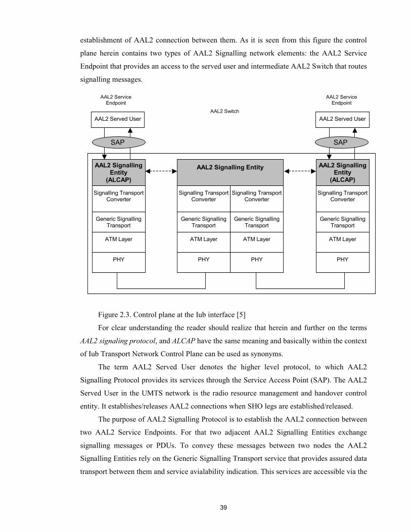
39
establishment of AAL2 connection between them. As it is seen from this figure the control
plane herein contains two types of AAL2 Signalling network elements: the AAL2 Service
Endpoint that provides an access to the served user and intermediate AAL2 Switch that routes
signalling messages.
Figure 2.3. Control plane at the Iub interface [5]
For clear understanding the reader should realize that herein and further on the terms
AAL2 signaling protocol, and ALCAP have the same meaning and basically within the context
of Iub Transport Network Control Plane can be used as synonyms.
The term AAL2 Served User denotes the higher level protocol, to which AAL2
Signalling Protocol provides its services through the Service Access Point (SAP). The AAL2
Served User in the UMTS network is the radio resource management and handover control
entity. It establishes/releases AAL2 connections when SHO legs are established/released.
The purpose of AAL2 Signalling Protocol is to establish the AAL2 connection between
two AAL2 Service Endpoints. For that two adjacent AAL2 Signalling Entities exchange
signalling messages or PDUs. To convey these messages between two nodes the AAL2
Signalling Entities rely on the Generic Signalling Transport service that provides assured data
transport between them and service avialability indication. This services are accessible via the
AAL2 Signalling Entity
(ALCAP)
Signalling Transport Converter
Generic Signalling Transport
ATM Layer
PHY
AAL2 Signalling Entity
Signalling Transport Converter
Generic Signalling Transport
ATM Layer
PHY
Signalling Transport Converter
Generic Signalling Transport
ATM Layer
PHY
AAL2 Signalling Entity
(ALCAP)
Signalling Transport Converter
Generic Signalling Transport
ATM Layer
PHY
AAL2 Served User AAL2 Served User
SAP SAP
AAL2 Service Endpoint
AAL2 Service Endpoint
AAL2 Switch
40
Generic Signalling Transport Access Point. In more details the ALCAP and its representative
at the Iub interface AAL2 Signalling protocol will be described in the next chapter.
In general the AAL2 is independent from the signalling transport, that's why on the
Figure 2.3 the latter is reffered to as a Generic signalling transport. Although an assured data
transport required with taking in to account massage size limits and etc. For that there is a
Signalling Transport Converter (STC) used to adapt generic signalling transport service to a
specific signalling transport service.
The Generic Signalling Transport consists of the Common Part of the AAL5
(Segmentation and Reassembly (SAR), Common Part Convergence Sublayer (CPCS)) and a
Service Specific Convergence Sublayer (SSCS) providing different services to its users. SSCS
on its top has the Service Specific Coordination Function, which directly provide the services
to the STC via its service access point. These services include:
- unacknowledged data transfer – without guarantee from cell losses or insertions;
- assured data transfer of point-to-point connections, essential for transfer signalling
information since it does relief its user from losses, corruption or disodering of data;
- establish and release of signalling AAL connection for services requiring assured
data transfer [8].
As the second part of SSCS (after SSCF) the Service Specific Connection Oriented
Protocol (SSCOP) supports the assured and unassured data transfer between its entities. It
provides the Sequence Integrity preserving the order of service data units (SDU) to be
transported, Error Correction, and Flow Control enabling the receiving entity to control the
transfer rate.
The Signalling Transport Converter provides the transparent data transfer between STC
served users (i.e. AAL2 Signalling Entities). In paticuar it supports the following services:
- providing independence from the underlying transmission media relieving then STC
users from all concerns how the STC service is provided;
- transparency of the information transfer, meaning that SCT does not interpret
somehow the information it transfers, thus the information content and coding have
no affect on the way it is transported;
- connection establishment and release in order to provide a permanent connection
service.
Such kind of transport architecture allows easily alter the transport technology to be
utilised, for example between ATM and IP.
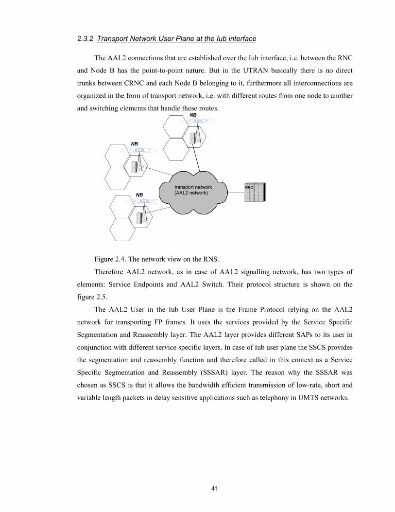
41
2.3.2 Transport Network User Plane at the Iub interface
The AAL2 connections that are established over the Iub interface, i.e. between the RNC
and Node B has the point-to-point nature. But in the UTRAN basically there is no direct
trunks between CRNC and each Node B belonging to it, furthermore all interconnections are
organized in the form of transport network, i.e. with different routes from one node to another
and switching elements that handle these routes.
Figure 2.4. The network view on the RNS.
Therefore AAL2 network, as in case of AAL2 signalling network, has two types of
elements: Service Endpoints and AAL2 Switch. Their protocol structure is shown on the
figure 2.5.
The AAL2 User in the Iub User Plane is the Frame Protocol relying on the AAL2
network for transporting FP frames. It uses the services provided by the Service Specific
Segmentation and Reassembly layer. The AAL2 layer provides different SAPs to its user in
conjunction with different service specific layers. In case of Iub user plane the SSCS provides
the segmentation and reassembly function and therefore called in this context as a Service
Specific Segmentation and Reassembly (SSSAR) layer. The reason why the SSSAR was
chosen as SSCS is that it allows the bandwidth efficient transmission of low-rate, short and
variable length packets in delay sensitive applications such as telephony in UMTS networks.
transport network (AAL2 network)
RNC
NB
NB
NB

42
Figure 2.5. User Plane at the Iub interface
In the AAL2 switch the AAL2 connections are cross-connected in the Common Part
Sublayer (CPS) with the help of Connection Identifier (CID) values that identify each AAL2
connection within an ATM Virtual Channel Connection (VCC).
In more details the AAL2 protocol stack and ALCAP as well as basic principles of
ATM will be discussed in the next chapter. In that chapter we're coming closer to the
immediate protocols playing direct or indirect role in the Transport Resource Management.
CPS of AAL2
ATM Layer
PHY
ATM Layer
PHY
Service Endpoint 2
AAL2 Switch SSSAR
CPS
ATM Layer
PHY
AAL2 User
SAP
AA
L2
Node B
Service Endpoint (RNC)
SSSAR
CPS
ATM Layer
PHY
AAL2 User
SAP
AA
L2
Service Endpoint 1
AAL2 Switch SSSAR
CPS
ATM Layer
PHY
AAL2 User
SAP
AA
L2
Node B
CPS of AAL2
ATM Layer
PHY
ATM Layer
PHY
Legend:
AAL2: ATM Adaptation Layer Type 2 SAP: Service Access Point CPS: Common Part Sublayer
SSSAR: Service Specific Segmentation and Reassembly
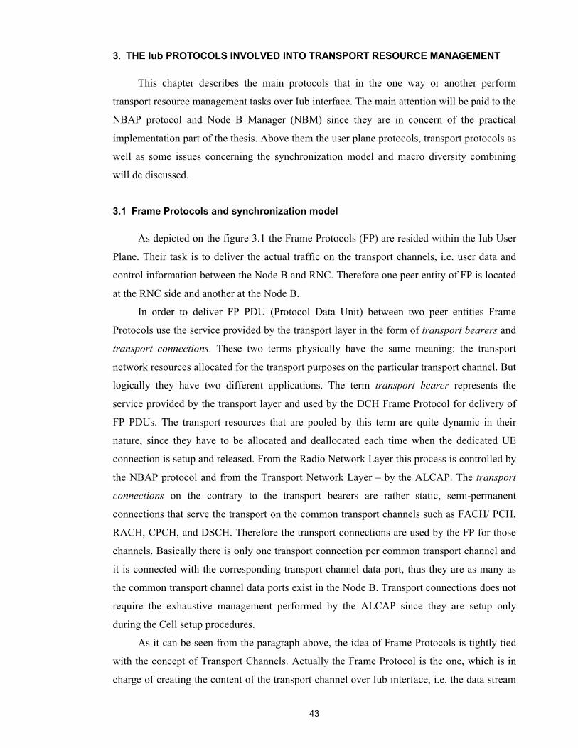
43
3. THE Iub PROTOCOLS INVOLVED INTO TRANSPORT RESOURCE MANAGEMENT
This chapter describes the main protocols that in the one way or another perform
transport resource management tasks over Iub interface. The main attention will be paid to the
NBAP protocol and Node B Manager (NBM) since they are in concern of the practical
implementation part of the thesis. Above them the user plane protocols, transport protocols as
well as some issues concerning the synchronization model and macro diversity combining
will de discussed.
3.1 Frame Protocols and synchronization model
As depicted on the figure 3.1 the Frame Protocols (FP) are resided within the Iub User
Plane. Their task is to deliver the actual traffic on the transport channels, i.e. user data and
control information between the Node B and RNC. Therefore one peer entity of FP is located
at the RNC side and another at the Node B.
In order to deliver FP PDU (Protocol Data Unit) between two peer entities Frame
Protocols use the service provided by the transport layer in the form of transport bearers and
transport connections. These two terms physically have the same meaning: the transport
network resources allocated for the transport purposes on the particular transport channel. But
logically they have two different applications. The term transport bearer represents the
service provided by the transport layer and used by the DCH Frame Protocol for delivery of
FP PDUs. The transport resources that are pooled by this term are quite dynamic in their
nature, since they have to be allocated and deallocated each time when the dedicated UE
connection is setup and released. From the Radio Network Layer this process is controlled by
the NBAP protocol and from the Transport Network Layer – by the ALCAP. The transport
connections on the contrary to the transport bearers are rather static, semi-permanent
connections that serve the transport on the common transport channels such as FACH/ PCH,
RACH, CPCH, and DSCH. Therefore the transport connections are used by the FP for those
channels. Basically there is only one transport connection per common transport channel and
it is connected with the corresponding transport channel data port, thus they are as many as
the common transport channel data ports exist in the Node B. Transport connections does not
require the exhaustive management performed by the ALCAP since they are setup only
during the Cell setup procedures.
As it can be seen from the paragraph above, the idea of Frame Protocols is tightly tied
with the concept of Transport Channels. Actually the Frame Protocol is the one, which is in
charge of creating the content of the transport channel over Iub interface, i.e. the data stream
44
to be transported over the given transport channel. Thus for each type of transport channel
there is a certain sort of FP.
Figure 3.1. Protocol stack for DCH, RACH, CPCH, FACH and DSCH Iub data stream
transport [9]
All the Frame Protocols are pretty similar in its structure, frame format and coding.
They all provide basic service: the transport of TBS (Transport Block Set) between the Node
B and CRNC, i.e. across the Iub interface. Herein we need to discover the terms Transport
Block and Transport Block Set, since they are essential for the discussion about the Frame
Protocols.
As stated in [10] the Transport Block (TB) is defined as the basic unit passed down to
L1 from MAC, for L1 processing. (The L1 protocol represents the physical layer on the Uu
interface.) An equivalent term for Transport Block is “MAC PDU”. If one takes a look at the
figure 1.16 he/she could encounter the MAC protocol entities resided both at the RNC and
Node B sides, but not presenting in the Iub interface protocol stack (figure 2.1). Actually, due
to the UTRAN internal protocol structure and functional division, the MAC protocol is
terminated at the RNC. Therefore there is no need to carry the MAC PDUs explicitly over the
Iub interface. But that information must be somehow handed from the RNC to the Node B in
order to pass it further towards the UE across the air interface. This is ensured by the Frame
Protocols. As it will be shown in the next subsection describing frame structure and coding
the Transport Blocks constitute the essential part of the frame's payload.
The Transport Block Set (TBS) in turn is defined as a set of Transport Blocks which is
passed to L1 from MAC at the same time instance using the same transport channel. An
equivalent term for Transport Block Set is “MAC PDU Set” [10].
PHY
Radio Network Layer
Transport Network
Layer
FP for DCH, RACH, CPCH/FACH/DSCH/
USCH[TDD]
AAL2 SSSAR (I.366.1)
ATM
AAL2 CPS (I.363.2)
45
Besides the transport of TBS across the Iub interface there is also some set of services
that may be supported or may not be supported by the given FP depending on the Transport
Channel it serves. That kind of services includes:
- Support of transport channel synchronization mechanism.
- Support of Node Synchronization
- Transport of outer loop power control information between the SRNC and the Node B.
- Transfer of DSCH Transport Format Indicator (TFI) from the SRNC and the Node B.
- Transfer of radio interface parameters from the SRNC and the Node B.
- Transfer of Rx timing deviation (for TDD mode only) from the Node B to the SRNC.
In fact all Frame Protocols are divided into two groups: FP for Dedicated Transport
Channel data streams and FP for Common Transport Channels data streams. Since there is a
single type of dedicated transport channels, DCH, there is only one FP representing that
group, DCH FP. For common transport channel data streams following Frame Protocols exist:
RACH FP, CPCH FP, FACH FP, and DSCH FP.
In order to provide the above mentioned services the FP performs the corresponding
procedures. The following is the examples of protocol procedures in case of DCH FP, those
are most relevant to the Transport Resource Management. The procedures are described in the
same sequence as the corresponding services were enumerated above.
Data Transfer
This procedure is executed each time when there is some data to be transmitted. The
data is organized in the form of frame with defined structure and transmitted every
transmission time interval from the SRNC to Node B for downlink transfer, and from Node B
to the SRNC for uplink transfer. Therefore data transfer is splitted into two procedures:
Uplink Data Transfer and Downlink Data Transfer as shown on the Figures 3.2 and 3.3.
In this section we are not intending to describe each procedure in very details, for more
information please refer to [11] and [12]. But from the transport management approach there
should be noted couple of aspects.
Each transport channel has the set of characteristics defining the way in which the
information is to be transferred on that given transport channel. This set is called Transport
Format, it is defined in [10] as a format offered by L1 to MAC for the delivery of a
Transport Block Set during a Transmission Time Interval on a Transport Channel. The
combination of currently valid Transport Formats on all Transport Channels of an UE, i.e.
containing one Transport Format from each Transport Channel is defined as a Transport
Format Combination (TFC) that is identified by the Transport Format Combination
Indicator.

46
The Transport Format has to be defined by the RNC for all transport channel when the
transport bearer is setup and signaled to the Node B. As a part of the Transport Resource
Management task this is ensured by the Application Protocols and namely NBAP at the Iub
interface. For example there are two modes that can be used for the Uplink Data Transfer:
silent and normal mode. The mode is selected by the SRNC and signaled to the Node B with
the relevant NBAP procedure. Namely it is done by the Radio Link Setup or Radio Link
Reconfiguration procedures. In details they will be described later on.
Figure 3.2 Uplink Data Transfer procedure Figure 3.3 Downlink Data Transfer
procedure
Considering the Downlink Data Transfer procedure there is one aspect worth to note
here not deepening into details, that in contrary to uplink transfer the downlink transfer
requires the transport bearer synchronization. Before this synchronization has been achieved
no data frame can be transmitted. The synchronization issues will be discovered later on in
this section.
Timing Adjustment
The Timing Adjustment procedure is used to keep the synchronization of the DCH data
stream in DL direction, i.e. to ensure that Node B receives DL frames in an appropriate time
for the transmission of the data in the air interface. Actually the information is transmitted
over the Uu (air) interface also in the form of frames (WCDMA frames) with the frame
interval 10 ms. Thus in order to avoid buffering and hence improve efficiency the transport
frames have to be synchronized in the downlink direction. This is the main purpose of the
Timing Adjustment procedure.
In order to support Timing Adjustment there is an arrival window defined in the Node
B. If a DL DATA FRAME arrives outside of that arrival window, the Node B sends the
TIMING ADJUSTMENT control frame to the RNC containing the measured Time of Arrival
(ToA) of that belated frame. Based on this RNC should adjust timing and send the next data
frame so that it would arrive within the defined arrival window. In order to address the
paticular frame each of them is assigned with the parameter called Connection Frame Number
SRNCNB
UL DATA FRAME
SRNC
DL DATA FRAME
NB

47
(CFN). The CFN parameter is linked to the physical frame numbering and indicates at which
time the user data should be transmitted over the radio interface or if it is a control frame at
which time a specific event should be applied. Hence, the CFN provides the sequence
integrity.
Herein there is a need to uncover the term Time of Arrival (ToA) as soon as we have
mentioned it above. One could imagine this parameter as an absolute value representing the
absolute time of the frame arrival. In reality it is not like this, ToA is rather relative parameter.
It is defined as the time difference between the end point of the DL arrival window (ToAWE)
and the actual arrival time of DL frame for specific CFN.
The ToAWE stands for the Time of Arrival Window Endpoint. It represents the time
point by which the DL data or control frame shall arrive to the Node B from the Iub interface.
In supplement to ToAWE there is another parameter called Time of Arrival Window
Startpoint (ToAWS). As one may guess it represents the time after which the DL frame shall
arrive to the Node B from Iub. These two parameters are set via the corresponding NBAP
procedures (previously mentioned Radio Link Setup and Radio Link Reconfiguration) for
each set of coordinated DCHs (and hence transport bearers) being setup.
DCH Synchronization
This procedure is used to achieve or restore the synchronization of the DCH data stream
in Downlink direction. This is accomplished by the exchanging of the control frames between
the RNC and the Node B.
The procedure is initiated by the SRNC sending a DL SYNCHRONIZATION control
frame towards the Node B. Upon reception that Node B immediately responds with UL
SYNCHRONIZATION contol frame inidicating the ToA for the DL SYNCHRONIZATION
control frame and its CFN. Based on the received ToA the SRNC is able to adjust timing and
upon that achieve synchronization.
Node Synchronization
Node Synchronization procedure is used by the SRNC to acquire information about the
Node B timing. The idea herein is to compare the information about the time point at which
RNC has sent the frame to the transport layer in effort to transfer it across the Iub interface
and the time point at which the Node B has received that frame from the transport layer. And
the same applied for the frame transfer in opposite direction. To resolve that task we need
three parameters denoted as follows:
- T1: RNC specific frame number (RFN) that indicates the time when the RNC sends
the control frame through the SAP (Service Access Point) provided by the transport
layer.

48
- T2: Node B specific frame number (BFN) indicating the time when the Node B
receives the correspondent control frame through the SAP from the transport layer.
- T3: Node B specific frame number (BFN) that indicates the time when the Node B
sends the frame through the SAP to the transport layer.
The procedure is initiated by the SRNC sending a DL NODE SYNCHRONIZATION
control frame to the Node B containing the T1 parameter. Upon reception of that frame the
Node B immediately responds with UL NODE SYNCHRONIZATION control frame
including the parameters T2 and T3 as well as the T1 indicating the initiating DL NODE
SYNCHRONIZATION control frame.
For description of other procedures performed by the DCH FP such as Outer Loop
Power Control Information Transfer, Rx Timing Deviation Measurement, DSCH TFCI
Signalling, Radio Interface Parameter Update and Timing advance for TDD mode please
refer to [11].
As it has already been mentioned the above presented procedure descriptions are valid
only for the DCH FP, since it was taken as a descriptive example. In case of Common
Transport Channel Frame Protocols the set of procedures (and thus data and control frames)
remains the same, exept that some of control procedures may be or may not be supported by
the given FP. The association between the transport bearer used by Common Transport
Channel and the data/control frames it supports is presented on the Table 3.1.
In this table 'yes' indicates that the control frame is applicable to the transport bearer and
'no' indicates that the control frame is not applicable to the transport bearer.
Associated control frames Transport
bearer used for
Associated data
frame Timing Adjust-
ment
DL Transport Channels
Synchroni-sation
Node Synchroni-
sation
Dynamic PUSCH
Assignment
Timing Advance
DSCH TFCI
Signalling
Outer Loop PC
Info Transfer
RACH RACH DATA FRAME
no no no no no no no
FACH FACH DATA FRAME
yes yes yes no no no no
CPCH CPCH DATA FRAME
no no no no No no no
PCH PCH DATA FRAME
yes yes yes no no no no
DSCH DSCH DATA FRAME
yes yes yes no no no no
USCH USCH DATA FRAME
no no no yes yes no yes
Table 3.1. Association between transport bearer and data/control frame [11]
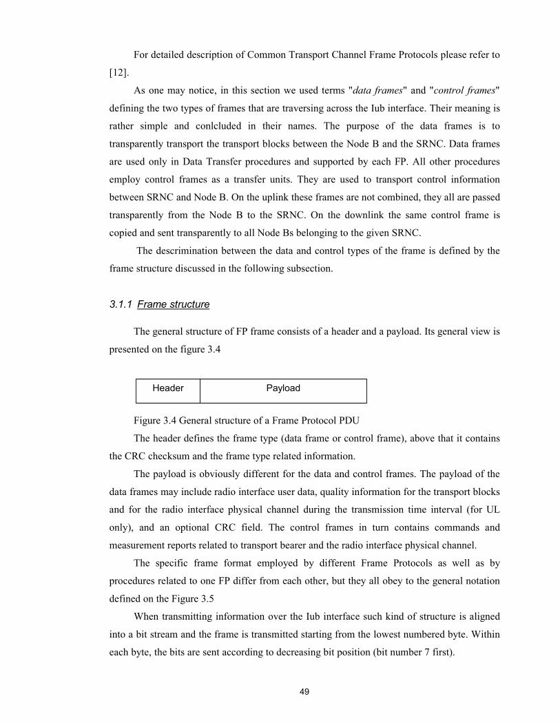
49
For detailed description of Common Transport Channel Frame Protocols please refer to
[12].
As one may notice, in this section we used terms "data frames" and "control frames"
defining the two types of frames that are traversing across the Iub interface. Their meaning is
rather simple and conlcluded in their names. The purpose of the data frames is to
transparently transport the transport blocks between the Node B and the SRNC. Data frames
are used only in Data Transfer procedures and supported by each FP. All other procedures
employ control frames as a transfer units. They are used to transport control information
between SRNC and Node B. On the uplink these frames are not combined, they all are passed
transparently from the Node B to the SRNC. On the downlink the same control frame is
copied and sent transparently to all Node Bs belonging to the given SRNC.
The descrimination between the data and control types of the frame is defined by the
frame structure discussed in the following subsection.
3.1.1 Frame structure
The general structure of FP frame consists of a header and a payload. Its general view is
presented on the figure 3.4
Figure 3.4 General structure of a Frame Protocol PDU
The header defines the frame type (data frame or control frame), above that it contains
the CRC checksum and the frame type related information.
The payload is obviously different for the data and control frames. The payload of the
data frames may include radio interface user data, quality information for the transport blocks
and for the radio interface physical channel during the transmission time interval (for UL
only), and an optional CRC field. The control frames in turn contains commands and
measurement reports related to transport bearer and the radio interface physical channel.
The specific frame format employed by different Frame Protocols as well as by
procedures related to one FP differ from each other, but they all obey to the general notation
defined on the Figure 3.5
When transmitting information over the Iub interface such kind of structure is aligned
into a bit stream and the frame is transmitted starting from the lowest numbered byte. Within
each byte, the bits are sent according to decreasing bit position (bit number 7 first).
Header Payload

50
7 6 5 4 3 2 1 0
Field 1 Field 2 Byte 1
Field 3 Byte 2
Field 3 (cont.) Field 4 Byte 3
Spare Extention
Figure 3.5. Example of notation used for definition of the frame structure [11]
As it was noted all the data and control frames belonging to different Frame Protocols
are different. The precise information about them can be found in [11] and [12]. The
following two figures give the generalized view at the data and control frames.
In the frame structures presented on these two figures the manadatory bit FT (Frame
Type) is the one, which discriminate between the two frame types. The FT set to '0' defines
the data frame type, otherwise set to '1' represents control frame type.
7 0
Frame CRC FT
Control Frame Type related information
Control information (TB)
Control information (TB cont.)
Spare extention
Fugure 3.6. General structure of the control frame
The Frame type related information in both control and data frames may include such
parameters as CFN, Transport Format Identification (TFI) – a label for a specific Transport
Format within a Transport Format Set. Above all TFI defines the size and the number of
Transport Blocks in the frame. The QE stands for Quality Estimate. This parameter is derived
from the Transport channel BER (Bit Error Rate). It is mandatory for data frames, control
frames may also use it.
Header (2 bytes)
Payload (variable length)

51
7 0
Header CRC FT
Data Frame Type related information
Data (TB)
Data (TB cont.)
QE
Spare extention
Payload checksum
Figure 3.7. General structure of the data frame
The above presented subsection was aimed to give the reader merely rough overview
about the way how the user information is handled on the Radio Network Layer. Further on it
is passed to the transport network and transmitted across the Iub interface. Since the transport
technology is of the arbitrary choice, due to the generic UTRAN interface model concepts,
from the Radio Network Layer point of view the transport technology as such does not affect
on the transport resource management tasks, these tasks have rather generic character. This
phenomena is guaranteed, as it was also mentioned previously, by the Transport Network
Control Plane and in particular ALCAP protocol. On that level the transport resource
management tasks have more specific nature and conducted in accordance with the transport
technology employed. Thus there are different levels of transport resource management
functionality embracing all layers from Network to Physical layer. In such a way the
decribing them all is a rather huge study and does not have a sense in case of rapidly changing
and evolving view on the transport technology in UTRAN. Therefore in this thesis we try to
discover rather general principles and components of the Transport Resource Management
over the Iub interface mostly from the Radio Network point of view. But at the same time we
cannot avoid issues tied with the currently adopted transport technology (meaning ATM with
AAL(n)), thus must present at least general overview of the interaction nature and basic
mechanisms within the Transport Network Layer in the aggregate with the Iub interface as a
whole. Actually this is the one of the objectives being pursued in this section and the chapter
as well.
Header (2 bytes)
Payload (variable length)
Optional
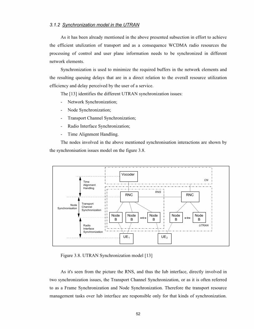
52
3.1.2 Synchronization model in the UTRAN
As it has been already mentioned in the above presented subsection in effort to achieve
the efficient utulization of transport and as a consequence WCDMA radio resources the
processing of control and user plane information needs to be synchronized in different
network elements.
Synchronization is used to minimize the required buffers in the network elements and
the resulting queuing delays that are in a direct relation to the overall resource utilization
efficiency and delay perceived by the user of a service.
The [13] identifies the different UTRAN synchronization issues:
- Network Synchronization;
- Node Synchronization;
- Transport Channel Synchronization;
- Radio Interface Synchronization;
- Time Alignment Handling.
The nodes involved in the above mentioned synchronisation interactions are shown by
the synchronisation issues model on the figure 3.8.
Figure 3.8. UTRAN Synchronization model [13]
As it's seen from the picture the RNS, and thus the Iub interface, directly involved in
two synchronization issues, the Transport Channel Synchronization, or as it is often referred
to as a Frame Synchronization and Node Synchronization. Therefore the transport resource
management tasks over Iub interface are responsible only for that kinds of synchronization.
Time Alignment Handling
Transport Channel Synchronization
Radio Interface Synchronization
NodeB
RNC
Vocoder
Node B
Node B
NodeB
NodeB
RNS
UTRAN
CN
UE1 UE2
RNC
NodeSynchronisation
53
The Transport Channel Synchronization is achieved by performing the DCH FP DCH
Synchronization procedure (or DL Transport Channel Synchronization in case of common
transport channel FPs), and Node Synchronization correspondingly by the FP Node
Synchronization procedure. These procedures were discovered previously in this section.
Following is the brief description of the synchronization issues in the UTRAN.
Time Alignment Handling synchronizes the transfer of information between the
diversity handover unit in RNC and vocoders or interworking functions in CN. It adapts to the
used data framing, and minimizes the delay in between by sending and receiving frames just
in time for processing.
The Radio Interface Synchronization relates to the timing of the radio frame
transmission. In FDD mode it is necessary to assure that the UE receives radio frames
synchronously from the different cells, in order to minimize UE buffers. This especially
relates to the macro-diversity case when there is a need to buffer out the transport delay
difference of the branches. The Frame Protocol frame indicates the start of the radio interface
transmission time by the Connection Frame Number (CFN) for each transport channel frame,
and this indication is executed per transport channel frame. The radio interface transmission
time is defined as a Cell System Frame Number (SFN). Then the mission of the Node B is to
determine the mapping between CFN of a FP frame and SFN of a radio frame.
The Node Synchronization relates to the estimation and compensation of timing
differences among UTRAN nodes. The Iub interface implies the "RNC-Node B"
synchronization. It allows to get knowledge of the timing differences between the RNC and
its Node Bs. Its use is mainly for determining good DL and UL offset values for transport
channel synchronization between RNC and their Node B's. Knowledge of timing relationships
between these nodes is based on a measurement procedure called Node Synchronization
procedure. The procedure is defined in the user plane for Iub DCH FP, DSCH FP, and FACH
FP. For information about this procedure see above.
The Transport Channel Synchronization mechanism defines synchronization of the
frame transport between RNC and Node B, considering radio interface timing. It ensures that
the same Transport Blocks are sent from the involved Node Bs towards one UE in the
downlink direction, and the same blocks sent by one UE and received by different Node Bs
are combined in RNC in the uplink direction. It is implemented via Frame Protocol's DCH
Synchronization procedures over Iub interface. The Frame Protocols are also used to
minimize the delay between the optimal arrival time of a Transport Block (Set) and the actual
measured arrival time in the Node B in the downlink direction. The actual arrival time can be
adjusted by either advancing or delaying the sending time of the frame from RNC. The

54
optimal arrival time is the radio interface transmission time reduced by a processing time of
the block in Node B. The Serving RNC controls the timing adjustment for both dedicated and
common transport channels. For the information about the realization of Transport Channel
Synchronization see above, the description of the FP procedures.
The presented material is rather brief overview of the UTRAN synchronization model,
for more information about all the synchronization issues in the UTRAN please refer to [13].
3.2 Macro Diversity Combining
In the previous section we discussed a lot about the splitting and combining of transport
frames during the Macro Diversity handling. From the Transport Resource Management point
of view it would be interesting to take a close look at the way how it is done on the ATM
transport level. This objective is pursued by this section.
Here we assume that the reader is familiar with the basic Macro Diversity principles,
since they have been discussed in the Section 1.2.2. In fact the Macro Diversity feature as
such relates to the Radio Resource Management, which is the subject of the separate study.
Therefore the aim of this section is to discover what kind of interactions on the transport level
is required for performing the Macro Diversity combining.
The Macro Diversity Combining is executed during the WCDMA soft handovers. It
means that the separate radio channels (legs) are combined to one transport channel in the
network in uplink direction and in the UE in downlink direction in effort to produce the
maximum obtainable quality. The status of particular radio frame is indicated to the Macro
Diversity Combining (MDC) entity (i.e. good or bad frame) and the MDC chooses the frame
with the best quality or take the sum of all frames (with the equal SFN) to be processed
further. These status (control) frames are transferred via inband signalling (i.e. within the FP
control frames). The MDC operation is rather simple from the processing perspective, but
may require quite large amount of memory in case the frames are long and/or bit rates are
high. Figure 3.9 shows the principle of the MDC.
As it was mentioned above in macro diversity depending on quality of signals received
from different legs they will be processed by some form of combining algorithm. The
algorithm may be based on selection of the signal from the leg with the best quality measure
(e.g. signal to noise ratio) or may add the signals from all legs weighed by the quality measure
on each leg. In fact, depending on how a UE roams, it may remain in the macro diversity
mode for an arbitrary period of time. During that time the signal quality measured on each leg
could be continuously changing.
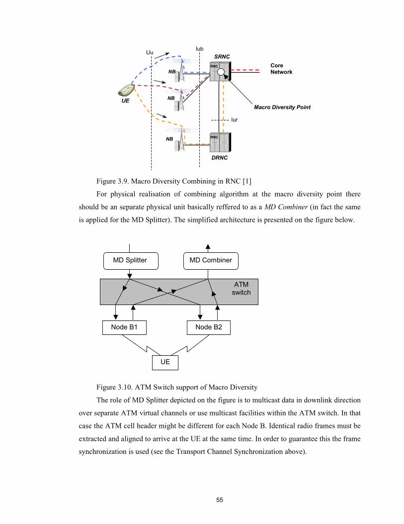
55
Figure 3.9. Macro Diversity Combining in RNC [1]
For physical realisation of combining algorithm at the macro diversity point there
should be an separate physical unit basically reffered to as a MD Combiner (in fact the same
is applied for the MD Splitter). The simplified architecture is presented on the figure below.
Figure 3.10. ATM Switch support of Macro Diversity
The role of MD Splitter depicted on the figure is to multicast data in downlink direction
over separate ATM virtual channels or use multicast facilities within the ATM switch. In that
case the ATM cell header might be different for each Node B. Identical radio frames must be
extracted and aligned to arrive at the UE at the same time. In order to guarantee this the frame
synchronization is used (see the Transport Channel Synchronization above).
RNCNB
RNC
NB
NB
UE
Uu Iub
Iur
Core Network
SRNC
DRNC
Macro Diversity Point
MD Splitter MD Combiner
ATM switch
Node B1 Node B2
UE
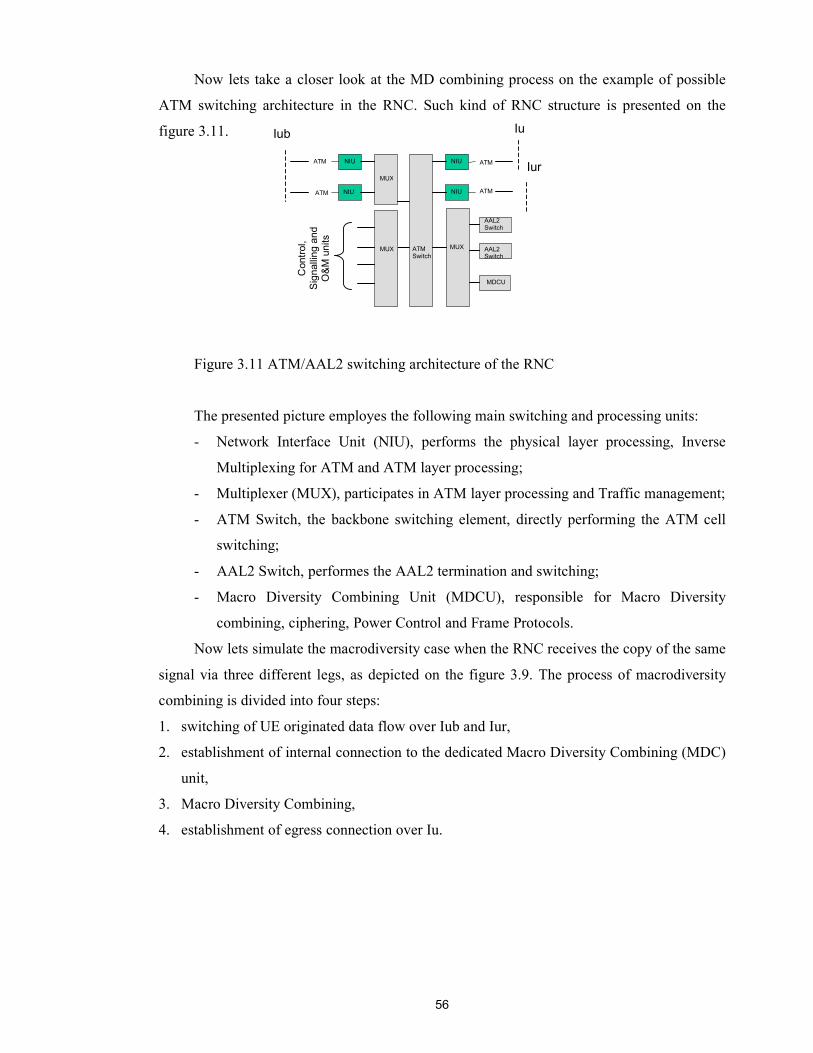
56
Now lets take a closer look at the MD combining process on the example of possible
ATM switching architecture in the RNC. Such kind of RNC structure is presented on the
figure 3.11.
Figure 3.11 ATM/AAL2 switching architecture of the RNC
The presented picture employes the following main switching and processing units:
- Network Interface Unit (NIU), performs the physical layer processing, Inverse
Multiplexing for ATM and ATM layer processing;
- Multiplexer (MUX), participates in ATM layer processing and Traffic management;
- ATM Switch, the backbone switching element, directly performing the ATM cell
switching;
- AAL2 Switch, performes the AAL2 termination and switching;
- Macro Diversity Combining Unit (MDCU), responsible for Macro Diversity
combining, ciphering, Power Control and Frame Protocols.
Now lets simulate the macrodiversity case when the RNC receives the copy of the same
signal via three different legs, as depicted on the figure 3.9. The process of macrodiversity
combining is divided into four steps:
1. switching of UE originated data flow over Iub and Iur,
2. establishment of internal connection to the dedicated Macro Diversity Combining (MDC)
unit,
3. Macro Diversity Combining,
4. establishment of egress connection over Iu.
ATM Switch
MUX
MUX
ATM ATMNIUNIU
NIU
MUX
ATMNIU
AAL2 Switch
MDCU
ATM
Iub Iu
Iur
Con
trol,
Sign
allin
g an
d O
&M u
nits
AAL2 Switch

57
UE originated data flow over Iub and Iur interfaces
Figure 3.11.1. Switching of UE originated data flow over Iub and Iur
The RNC receives three copies of frame via three legs. For transmission the
ATM/AAL2 connection are used. The received ATM cells are always switched through MUX
and ATM Switch to a dedicated AAL2 unit (AAL2 Switch) on a cell-by-cell basis without
any changes in the ATM payload.
Internal connection to the dedicated MDC unit
Figure 3.11.2. Establishment of internal connection to the dedicated MDC unit
Then the AAL2 packets (minicells) are demultiplexed in the AAL2 Switch. Each
minicell is packed into one or several ATM cells and transmitted over internal connections
towards the dedicated macrodiversity combining unit (MDCU). It should be noted that the
AAL2 switching is done only in the AAL2 Switch functional unit, all other elements perform
switching at the ATM level.
ATM Switch
MUX
MUX
ATM ATMNIUNIU
NIU
MUX
ATMNIU
MDCU
ATM
Iub Iu
Iur
Con
trol,
Sign
allin
g an
d O
&M
uni
ts
Leg 1
Leg 2 Leg 3
MUX
MUX
ATM ATMNIUNIU
NIU
MUX
ATMNIU
MDCU
ATM
Iub Iu
Iur
Con
trol,
Sign
allin
g an
d O
&M
uni
ts
AAL2 minicells
Pad
ATM Switch
AAL2 Switch AAL2 Switch
AAL2 Switch AAL2 Switch

58
Macro Diversity Combining
Figure 3.11.3. Macro Diversity Combining
Macro Diversity Combining is performed in the MDCU. In practice the signals carried
in the AAL0/5 cells – each carrying a single AAL2 minicell – are combined according to the
specific algorithm. After signal combining, a single AAL0/5 cell is transmitted to one of the
AAL2 Switching units for external transmission towards the core network.
Establishment of egress connection over Iu
Figure 3.11.4 Establishment of egress connection over Iu
Now the outgoing leg is established from NUI to AAL2 Switch. The AAL2 Switching
unit takes care of AAL2 multiplexing to ensure that the external transmission resources are
utilised as efficiently as possible. A leg connector maps the internal connection from the
MDCU to the outgoing leg. Now the combined frame is ready to traverse further, towards the
core network.
Note: the RNC architecture is highly vendor depending solution, thus the ATM/AAL(n)
switching and concrete MDC unit implementation might be realised in different ways. Here
MUX
MUX
ATM ATMNIUNIU
NIU
MUX
ATMNIU
MDCU
ATM
Iub Iu
Iur
Con
trol,
Sign
allin
g an
d O
&M
uni
ts
+
+
=
MUX
MUX
ATM ATMNIUNIU
NIU
MUX
ATMNIU
MDCU
ATM
Iub Iu
Iur
Con
trol,
Sign
allin
g an
d O
&M
uni
ts
Leg connector
ATM Switch
AAL2 Switch
AAL2 Switch
ATM Switch
AAL2 Switch
AAL2 Switch

59
the merely demonstrative example of RNC is presented in order to show the basic principles
of macrodiversity combining within RNC.
Through the whole discussion about the Transport Resourse Management we have been
talking a lot about the the ATM technology and its place in the UTRAN interfaces. But in
order to clearly understand what the transport resources are as such regarding to the employed
technology one has to be aware of its basic principles and mechanisms. The next section is
aimed to give the reader some overview of the ATM together with its AALs as transport
technology.
3.3 ATM stack and adaptation layers
3.3.1 Basic concepts of ATM
ATM is a cell switched, connection-oriented networking technology that provides
dedicated, high-speed connections to virtually an unlimited number of users. It operates on a
cell-based fast-packet communication method that supports transfer rates from 1.544 Mbps to
10 Gbps. Dedicated media connections running in parallel allow an ATM switch to
simultaneously support multiple conversations, eliminating the bandwidth contention and data
bottlenecks found on shared-media networks such as Ethernet, Token Ring and FDDI.
Because of its asynchronous nature, ATM is more efficient than synchronous
technologies, such as time-division multiplexing (TDM). With TDM each user is assigned to a
time slot, and no other one can send in that time slot. If a station has much data to send, it can
send only when its time slot comes up, even if all other time slots are empty. However if a
station has nothing to transmit when its time slot comes up, the time slot is sent empty and
wasted. Because ATM in contrary to TDM is asynchronous, there is no strict assignment
between users and time slots, rather the time slots are available on demand with information
identifying the source of the transmission contained in the header of each ATM cell.
What is the ATM cell? The cell in ATM is the fixed-size packet, which serves as a
information transfer unit over ATM networks. Each cell consists of 53 octets (or bytes) shared
between 5-byte-long header and remaining 48-byte-long payload. Why 53 bytes? A large
payload is advantageous since more data can be sent with fewer overheads wasted on
unneeded headers. Also payloads are traditionally sized in powers of 2. The original
proposed sizes for the ATM payload were 32 and 64 bytes. Keeping a small payload
increases speed and is ideal for delay sensitive data such as voice communications. Having a
large 64 byte payload is better for transferring large amounts of data, but in voice
communications problems with echo occurred. So 48 bytes was decided as a compromise,
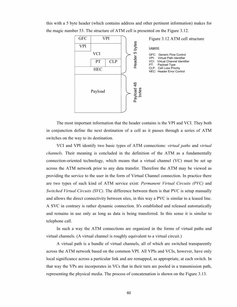
60
this with a 5 byte header (which contains address and other pertinent information) makes for
the magic number 53. The structure of ATM cell is presented on the Figure 3.12.
GFC VPI
VPI
VCI
PT CLP
HEC
Payload
The most important information that the header contains is the VPI and VCI. They both
in conjunction define the next destination of a cell as it passes through a series of ATM
switches on the way to its destination.
VCI and VPI identify two basic types of ATM connections: virtual paths and virtual
channels. Their meaning is concluded in the definition of the ATM as a fundamentally
connection-oriented technology, which means that a virtual channel (VC) must be set up
across the ATM network prior to any data transfer. Therefore the ATM may be viewed as
providing the service to the user in the form of Virtual Channel connection. In practice there
are two types of such kind of ATM service exist: Permanent Virtual Circuits (PVC) and
Switched Virtual Circuits (SVC). The difference between them is that PVC is setup manually
and allows the direct connectivity between sites, in this way a PVC is similar to a leased line.
A SVC in contrary is rather dynamic connection. It's established and released automatically
and remains in use only as long as data is being transferred. In this sense it is similar to
telephone call.
In such a way the ATM connections are organized in the forms of virtual paths and
virtual channels. (A virtual channel is roughly equivalent to a virtual circuit.)
A virtual path is a bundle of virtual channels, all of which are switched transparently
across the ATM network based on the common VPI. All VPIs and VCIs, however, have only
local significance across a particular link and are remapped, as appropriate, at each switch. In
that way the VPs are incorporates in VCs that in their turn are pooled in a transmission path,
representing the physical media. The process of concatenation is shown on the Figure 3.13.
Hea
der 5
byt
es
Payl
oad
48
b yte
s
Figure 3.12 ATM cell structure Legend: GFC: Generic Flow Control VPI: Virtual Path Identifier VCI: Virtual Channel Identifier PT: Payload Type CLP: Cell Loss Priority HEC: Header Error Control
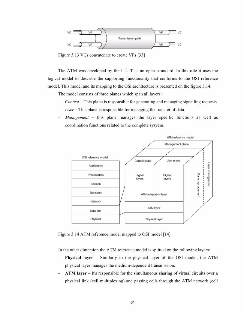
61
Figure 3.13 VCs concatenate to create VPs [33]
The ATM was developed by the ITU-T as an open strandard. In this role it uses the
logical model to describe the supporting functionality that conforms to the OSI reference
model. This model and its mapping to the OSI architecture is presented on the figure 3.14.
The model consists of three planes which span all layers:
- Control – This plane is responsible for generating and managing signalling requests.
- User – This plane is responsible for managing the transfer of data.
- Management – this plane manages the layer specific functions as well as
coordination functions related to the complete sysyem.
Figure 3.14 ATM reference model mapped to OSI model [14].
In the other dimention the ATM reference model is splitted on the following layers:
- Physical layer – Similarly to the physical layer of the OSI model, the ATM
physical layer manages the medium-dependent transmission.
- ATM layer – It's responsible for the simultaneous sharing of virtual circuits over a
physical link (cell multiplexing) and passing cells through the ATM network (cell
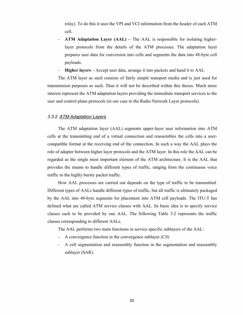
62
relay). To do this it uses the VPI and VCI information from the header of each ATM
cell.
- ATM Adaptation Layer (AAL) – The AAL is responsible for isolating higher-
layer protocols from the details of the ATM processes. The adaptation layer
prepares user data for conversion into cells and segments the data into 48-byte cell
payloads.
- Higher layers – Accept user data, arrange it into packets and hand it to AAL.
The ATM layer as such consists of fairly simple transport media and is just used for
transmission purposes as such. Thus it will not be described within this theses. Much more
interest represent the ATM adaptation layers providing the immediate transport services to the
user and control plane protocols (in our case to the Radio Network Layer protocols).
3.3.2 ATM Adaptation Layers
The ATM adaptation layer (AAL) segments upper-layer user information into ATM
cells at the transmitting end of a virtual connection and reassembles the cells into a user-
compatible format at the receiving end of the connection. In such a way the AAL plays the
role of adapter between higher layer protocols and the ATM layer. In this role the AAL can be
regarded as the single most important element of the ATM architecture. It is the AAL that
provides the means to handle different types of traffic, ranging from the continuous voice
traffic to the highly bursty packet traffic.
How AAL processes are carried out depends on the type of traffic to be transmitted.
Different types of AALs handle different types of traffic, but all traffic is ultimately packaged
by the AAL into 48-byte segments for placement into ATM cell payloads. The ITU-T has
defined what are called ATM service classes with AAL. Its basic idea is to specify service
classes each to be provided by one AAL. The following Table 3.2 represents the traffic
classes corresponding to different AALs.
The AAL performs two main functions in service specific sublayers of the AAL:
- A convergence function in the convergence sublayer (CS)
- A cell segmentation and reassembly function in the segmentation and reassembly
sublayer (SAR).

63
Traffic Class
Source & Destination
Connection Bit Rate Typical Use
Class A (AAL1)
Synchronised Connection-oriented Constant Fixed Connection
Class B (AAL2)
Synchronised Connection-oriented Variable Audio & Video
Class C (AAL3/4)
Not Synchronised Connection-oriented Variable Frame Relay
Class D (AAL5)
Not Synchronised Connectionless Variable Packet-switched services
Table 3.2 ATM traffic classes supported by AAL
The purpose of these two sublayers is to convert user data into 48-byte cell payloads at
the same time maintaining the integrity and identity of the user data. They are briefly
described below:
Convergence sublayer (CS). The CS provides appropriate traffic services to higher
layer protocols.
Once connection is established between communicating ATM entities with an
appropriate quality of service (QoS), the CS accept higher level traffic for transmission
through the network. Depending on the traffic type certain header and/or trailer fields are
added to the user data payload and formed into information packets called convergence
sublayer protocol data units (CS-PDUs). These packets are passed further to the segmentation
and reassembly sublayer (SAR) of the AAL for further processing.
Segmentation and Reassembly (SAR) sublayer. The SAR segments each CS-PDU
received from the CS into smaller units and adds a header and/or trailer field, depending on
the traffic type, to form 48-byte payloads called segmentation and reassembly sublayer
protocol data units (SAR-PDUs). The generalized processes through which the user data
stream is transformed into appropriate ATM data units are illustrated in figure 3.15.
Figure 3.15. Data processing relationships in AAL
User data stream
CS-PDU CS-PDU CS-PDU
SAR-PDU SAR-PDU SAR-PDU SAR-PDU . . . .
CS process
SAR process

64
Once the user data is arranged into SAR-PDUs by the AAL layer, they are passed to the
ATM layer which packages the data into 53-byte ATM cells, making them suitable for
transport as outgoing ATM cells by the physical layer, as indicated in figure 3.16.
Figure 3.16. Arranging ATM data for transport by physical layer
Conversely upon receiving of incoming ATM cells from the physical layer, the AAL
removes any AAL specific information from each cell payload and reassembles the packet for
providing to higher layer protocols in the form expected by the user application.
As it was stated, for different types of traffic the different AALs are used, see table 3.2.
In practice, the ATM together with particular AAL can be used in different network
applications. It was naturally specified as a high-speed transfer technology for voice, video
and data over the public and private networks (e.g. LANs and WANs). But in this thesis we
concern ATM/AAL technology only from the telecommunication use perspective, particularly
its use within the UTRAN. Therefore it's worth to concentrate on the two types of AAL
employed by the Iub interface as a part of UTRAN, AAL2 and AAL5.
3.3.2.1 ATM Adaptation Layer 2
The ATM Adaptation Layer 2, AAL2, has recently been defined in the ITU-T. It
provides both high efficiency and low delay in the use of bandwidth resources, keeping the
low complexity. User application packets of variable length can be transported in an AAL2
connection and it is ideal for carrying compressed voice and low bit rate data. Importantly,
AAL2 provides the capability to multiplex application packets from different user connections
over the same ATM connection.
The AAL2 is subdivided into two layers, the Common Part Sublayer (CPS) and the
Service Specific Convergence Sublayer (SSCS), please refer to figure 3.17. The general
division into Convergence Sublayer (CS) and the Segmentation and Reassembly (SAR)
functionality is not visible in AAL2 architecture, rather the standard merged the SAR and
Common Part Convergence Sublayer (CPCS), being the part of CS, to the CPS.
AAL process
48 bytes
ATM process
48 bytes
5-byte header
48 bytes
5-byteheader
User data 53-byte ATM cells
To physical layer
48 bytes

65
SSCS
CPCS
SAR
Figure 3.17. AAL2 protocol stack
The Common Part Sublayer of AAL2 (AAL2-CPS) was proposed to adapt the powerful
capabilities of ATM to the traffic requirements of low and variable bit rate applications such
as compressed voice used in cellular environments. AAL2-CPS achieves both low
packetization delay and high bandwidth efficiency by:
a) allowing variable packet length, from 1 octet to 45 octets.
b) multiplexing several AAL2 connections in an ATM virtual channel connection
(VCC).
Point a) allows easy control of the packetization delay by letting the application choose
the most convenient maximum packet size for its delay requirements. The lower the size the
lower the delay. Point b) allows efficient use of bandwidth resources. Instead of having user
data partially filling an ATM cell, AAL2-CPS will fill the cell with AAL2 packets from
several active AAL2 connections.
There are two different message formats in AAL2 that have to be distinguished, the
CPS packet and the CPS Protocol Data Unit (PDU), which is then mapped to an ATM Service
Data Unit (SDU). The AAL2-CPS packet format is shown in figure 3.17.
CID LI UUI HEC CPS-Packet payload (1..45/64 octets)
Figure 3.18. AAL2-CPS packet format
The CPS packet consists of 3 octets header and up to 45 octets payload. The actual
length of the payload is indicated in the "length indicator" (LI) field. A "user-to-user
information" (UUI) field has been included for upper layers (users) to transparently convey
information (e.g. some SSCS use it to convey a sequence number and/or the type of voice-
codec used). An 8 bits "connection identifier" (CID) identifies individual AAL2 connections
inside an AAL2 link (ATM VCC set up for transport of AAL2 traffic). Finally, the 5 bits
CRC field protects the AAL2-CPS packet header from transmission errors (the payload is not
protected).
CS in general AAL architecture
CPS
CPS-Packet Header (3 octets)
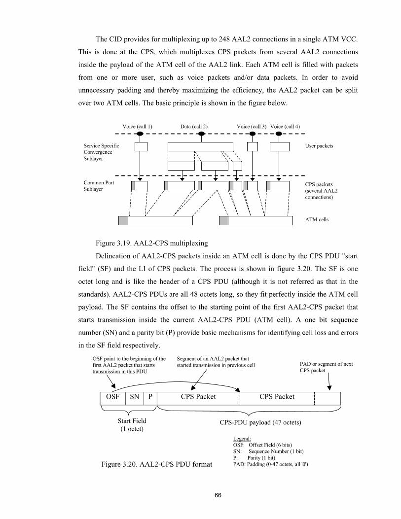
66
The CID provides for multiplexing up to 248 AAL2 connections in a single ATM VCC.
This is done at the CPS, which multiplexes CPS packets from several AAL2 connections
inside the payload of the ATM cell of the AAL2 link. Each ATM cell is filled with packets
from one or more user, such as voice packets and/or data packets. In order to avoid
unnecessary padding and thereby maximizing the efficiency, the AAL2 packet can be split
over two ATM cells. The basic principle is shown in the figure below.
Figure 3.19. AAL2-CPS multiplexing
Delineation of AAL2-CPS packets inside an ATM cell is done by the CPS PDU "start
field" (SF) and the LI of CPS packets. The process is shown in figure 3.20. The SF is one
octet long and is like the header of a CPS PDU (although it is not referred as that in the
standards). AAL2-CPS PDUs are all 48 octets long, so they fit perfectly inside the ATM cell
payload. The SF contains the offset to the starting point of the first AAL2-CPS packet that
starts transmission inside the current AAL2-CPS PDU (ATM cell). A one bit sequence
number (SN) and a parity bit (P) provide basic mechanisms for identifying cell loss and errors
in the SF field respectively.
OSF SN P CPS Packet CPS Packet
Voice (call 1) Data (call 2) Voice (call 3) Voice (call 4)
CPS packets (several AAL2 connections)
User packets
ATM cells
Service Specific Convergence Sublayer
Common Part Sublayer
CPS-PDU payload (47 octets) Start Field (1 octet)
OSF point to the beginning of the first AAL2 packet that starts transmission in this PDU
Segment of an AAL2 packet that started transmission in previous cell PAD or segment of next
CPS packet
Legend: OSF: Offset Field (6 bits) SN: Sequence Number (1 bit) P: Parity (1 bit) PAD: Padding (0-47 octets, all '0') Figure 3.20. AAL2-CPS PDU format
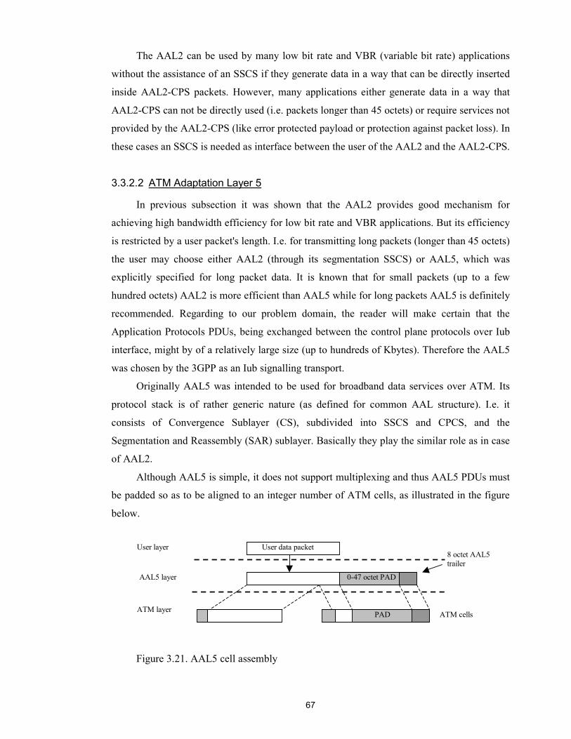
67
The AAL2 can be used by many low bit rate and VBR (variable bit rate) applications
without the assistance of an SSCS if they generate data in a way that can be directly inserted
inside AAL2-CPS packets. However, many applications either generate data in a way that
AAL2-CPS can not be directly used (i.e. packets longer than 45 octets) or require services not
provided by the AAL2-CPS (like error protected payload or protection against packet loss). In
these cases an SSCS is needed as interface between the user of the AAL2 and the AAL2-CPS.
3.3.2.2 ATM Adaptation Layer 5
In previous subsection it was shown that the AAL2 provides good mechanism for
achieving high bandwidth efficiency for low bit rate and VBR applications. But its efficiency
is restricted by a user packet's length. I.e. for transmitting long packets (longer than 45 octets)
the user may choose either AAL2 (through its segmentation SSCS) or AAL5, which was
explicitly specified for long packet data. It is known that for small packets (up to a few
hundred octets) AAL2 is more efficient than AAL5 while for long packets AAL5 is definitely
recommended. Regarding to our problem domain, the reader will make certain that the
Application Protocols PDUs, being exchanged between the control plane protocols over Iub
interface, might by of a relatively large size (up to hundreds of Kbytes). Therefore the AAL5
was chosen by the 3GPP as an Iub signalling transport.
Originally AAL5 was intended to be used for broadband data services over ATM. Its
protocol stack is of rather generic nature (as defined for common AAL structure). I.e. it
consists of Convergence Sublayer (CS), subdivided into SSCS and CPCS, and the
Segmentation and Reassembly (SAR) sublayer. Basically they play the similar role as in case
of AAL2.
Although AAL5 is simple, it does not support multiplexing and thus AAL5 PDUs must
be padded so as to be aligned to an integer number of ATM cells, as illustrated in the figure
below.
Figure 3.21. AAL5 cell assembly
User layer 8 octet AAL5 trailer
0-47 octet PAD
ATM cells
AAL5 layer
ATM layer
User data packet
PAD
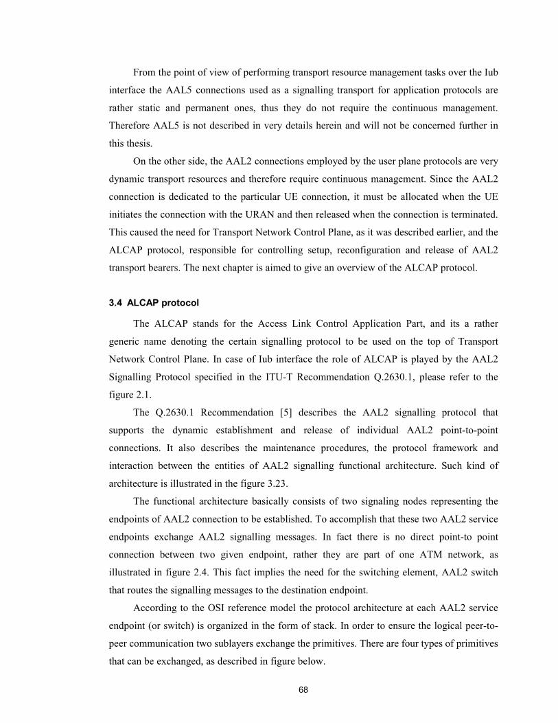
68
From the point of view of performing transport resource management tasks over the Iub
interface the AAL5 connections used as a signalling transport for application protocols are
rather static and permanent ones, thus they do not require the continuous management.
Therefore AAL5 is not described in very details herein and will not be concerned further in
this thesis.
On the other side, the AAL2 connections employed by the user plane protocols are very
dynamic transport resources and therefore require continuous management. Since the AAL2
connection is dedicated to the particular UE connection, it must be allocated when the UE
initiates the connection with the URAN and then released when the connection is terminated.
This caused the need for Transport Network Control Plane, as it was described earlier, and the
ALCAP protocol, responsible for controlling setup, reconfiguration and release of AAL2
transport bearers. The next chapter is aimed to give an overview of the ALCAP protocol.
3.4 ALCAP protocol
The ALCAP stands for the Access Link Control Application Part, and its a rather
generic name denoting the certain signalling protocol to be used on the top of Transport
Network Control Plane. In case of Iub interface the role of ALCAP is played by the AAL2
Signalling Protocol specified in the ITU-T Recommendation Q.2630.1, please refer to the
figure 2.1.
The Q.2630.1 Recommendation [5] describes the AAL2 signalling protocol that
supports the dynamic establishment and release of individual AAL2 point-to-point
connections. It also describes the maintenance procedures, the protocol framework and
interaction between the entities of AAL2 signalling functional architecture. Such kind of
architecture is illustrated in the figure 3.23.
The functional architecture basically consists of two signaling nodes representing the
endpoints of AAL2 connection to be established. To accomplish that these two AAL2 service
endpoints exchange AAL2 signalling messages. In fact there is no direct point-to point
connection between two given endpoint, rather they are part of one ATM network, as
illustrated in figure 2.4. This fact implies the need for the switching element, AAL2 switch
that routes the signalling messages to the destination endpoint.
According to the OSI reference model the protocol architecture at each AAL2 service
endpoint (or switch) is organized in the form of stack. In order to ensure the logical peer-to-
peer communication two sublayers exchange the primitives. There are four types of primitives
that can be exchanged, as described in figure below.

69
Figure 3.22 Primitive exchange in the OSI model
The N-Layer entity may request a service from the N-1 entity. On the receiving side
(peer) the Indication message from the N-1 Layer acknowledges to the upper N-Layer that the
N-1 entity is ready. The Response is the reaction of the N Layer to the Indication message of
the layer below in order to be replied to the peer as an acknowledge. The Confirmation
message is sent by the N-1 layer to acknowledge that the service required is completed.
Figure 3.23 AAL Type 2 signalling protocol reference architecture [5]
The scope of Recommendation Q.2630.1 is limited within the definition of AAL2
signalling entity and its interfaces to other layers through Service Access Points (SAP). Thus
the signalling transport and signalling transport converters that provide assured data transfer
Entity Layer N
Entity Layer N-1
Entity Layer N
Entity Layer N-1
Peer to Peer
communication
Confirm Request
IndicationResponse
AAL type 2switch
A2SU-SAP A2SU-SAP
AAL type 2 Signalling message
AAL type 2 Signalling message
(Note)
GST-SAP GST-SAP GST-SAP GST-SAP
Signalling transport(e.g. MTP3b + NNI-SAAL, UNI-SAAL, SSCOP, ...)
AAL type 2 service endpoint
Signalling transport converter
Signallingtransportconverter
Signallingtransportconverter
Signallingtransportconverter
AAL type 2 served user
Protocol entity
Protocolentity
Protocolentity
Protocolentity
Nodal function
Nodalfunction
Nodalfunction
AAL type 2 signalling entity
AAL type 2signalling entity
AAL type 2signalling entity
(Note) (Note) (Note)
NOTE – In every AAL type 2 node, a signalling transport converter instance is associated with each AAL type 2 signalling transport
AAL type 2 service endpoint
AAL type 2 served user
Signalling transport(e.g. MTP3b + NNI-SAAL, UNI-SAAL, SSCOP, ...)
Laye
r m
anag
emen
t
Laye
r m
anag
emen
t
Laye
r m
anag
emen
t
LM-S
AP
LM-S
AP
LM-S
AP
70
between AAL2 signalling entities are beyond the scope of ALCAP specification. For
information about the ALCAP underlying protocol stack at the Iub interface, please refer to
figure 2.1.
The AAL2 signalling entity consists of two parts, the protocol entity and the nodal
function. The protocol entity is the one, which performs all the signalling, and maintenance
related functionality. The protocol entities are absolutely the same at AAL2 service endpoints
as well as at AAL2 switches. This fact makes the AAL2 signalling protocol to be considered
as a symmetric. The protocol entity is subdivided into several procedures: outgoing protocol
procedures, incoming protocol procedures and maintenance protocol procedures.
The outgoing protocol procedures provide the mechanism to initiate an AAL type 2
connection request. The incoming protocol procedures are applied when a request for an AAL
type 2 connection is received from a peer entity. Both of these procedures provide for the
orderly release of an AAL type 2 connection. The maintenance protocol procedures provide
the mechanisms to align the status of the AAL type 2 resources (available/not available,
blocked/unblocked) at the two adjacent AAL type 2 nodes and the procedures to block and
unblock an AAL type 2 path.
The nodal function provides the bridge between incoming and outgoing protocol
entities, performs the routing functionality, and keeps track of the AAL type 2 path resources.
As illustrated in the figure 3.23, the AAL2 signalling entity has three interfaces with
other layers and thus three SAPs:
- through A2SU-SAP - the interface between AAL2 signalling entity and the AAL2
served user – the interface to a higher layer protocol,
- through GST-SAP - the interface between AAL2 signalling entity and the generic
signalling transport – the interface to a lower layer protocol,
- through LM-SAP - the interface between AAL2 signalling entity and layer
management – the internal interface to the network management system.
Since the main objective of this thesis is to study the transport resource management
mainly from the Radio Network Layer point of view, the interface with the AAL2 served user,
resided at the Radio Network Layer and the one which directly commands ALCAP to
establish or release transport (AAL2) connection, is of the most interest for us. The other
interfaces are not described herein, for detailed information about them, please refer to [5].
The AAL type 2 signalling entity provides the following services to the AAL type 2
served user across the A2SU-SAP:
- establishment of AAL type 2 connections; and
- release of AAL type 2 connections.

71
Note: the Recommendation Q.2630.2 (Capability Set 2) adds the modification of AAL2
connection resources service, please refer to [15]. This capability is not described here.
For provisioning these services the A2SU-SAP implies the following primitives to be
exchanged between the AAL2 signalling entity and its served user (here in and further on the
reader may also read: between ALCAP and Radio Network Layer Control Plane protocol):
ESTABLISH.request/indication/confirm, RELAESE/request/indication/confirm.
Theses primitives are used by the originating served user to initiate AAL2 connection
establishment (ESTABLISH.request) and by the originating and destination served users to
initiate the release of the connection (RELEASE.request); and by the AAL2 signalling entities
to indicate an incoming connection (ESTABLISH.indication/confirm) to the destination
served user, and notifying either the originating or destination served user of the release of a
connection (RELEASE.indication/confirm). In fact these primitives have rather descriptive
character, in practice their use is implementation dependent. However the general framework
has to be kept, meaning that the specific implementation must rely on the generic primitive
structure containing basic parameters to be carried by the given primitive.
The primitive's parameters represent the information, passed by either served user or
ALCAP. The most important parameters needed for transport bearer (AAL2 connection)
establishment are:
- AAL2 Service Endpoint Address – this parameter carries the endpoint address of
the destination. In practice it defines the exact location of the endpoint within the
transport network and directly used in routing the signalling message to its
destination. That's why in Radio Network Layer application protocol terminology
the A2EA is also referred to as a Transport Layer Address, the reader will face it
later.
- Served User Generated Reference – this parameter carries a reference provided by
the originating AAL2 served user. It's used by the APs to ensure the binding
mechanism between the Transport and Radio Network Layer addresses. At the
Radio Network Layer this parameter is referred to as a Binding ID. This will be
described later in the section devoted to NBAP.
- Service Specific Information (SSCS Information) – this parameter identifies the
type and capabilities of AAL2 SSCS layer (for more information about SSCS,
please refer to section 3.3.2.1).
- Link Characteristics – this parameter gives an indication of the resources required
for the AAL2 connection and is used only for AAL2 path selection and connection
admission control.

72
Once the AAL2 connection is established, the ALCAP responds to its served user with
the primitive containing the reference parameter uniquely identifying the particular
established connection. That parameter is used in each primitive to address the certain AAL2
connection instance (for example during AAL2 connection release). This reference parameter
is not specified by the Q.2630.1 and considered to be an implementation detail. Therefore it
won't be mentioned any more in this section, but will be seen in the next chapter describing
NBAP implementation issues.
In effort to achieve the better understanding of the nature of processes running within
the ALCAP let us present the following descriptive example of AAL2 connection
establishment.
Lets start from the very beginning. When the UE (or CN) initiates the establishment of
dedicated connection the UTRAN must provide, as its service, the Radio Access Bearer for
that connection. The Iub interface, in particular, has to provide the transport bearer between
the RNC and Node B, as a part of RAB. For that the Iub Radio Network Layer protocol
(NBAP for example) commands the ALCAP to establish transport bearer by sending
ESTABLISH.request primitive with the appropriate parameters.
When the nodal function receives an ESTABLISH.request primitive from the AAL2
served user, it analyses the routing information and selects a route with sufficient AAL2 path
resources to the succeeding AAL2 node. It then selects an AAL2 path from within that route
which is able to accommodate the new connection. The routing is typically based on
addressing information, link characteristic and other information (such as SSCS information)
passed in the primitive.
AAL2 node internal resources are allocated to establish an AAL2 node internal path for
the new connection from the originating AAL2 served user to the outgoing AAL2 path. On
the selected outgoing AAL2 path, the Connection Identifier (CID) and other resources (e.g.
indicated by link characteristic or SSCS information) are allocated for the outgoing AAL2
link. Once the resources have been allocated an outgoing protocol entity instance is invoked
and the following parameters are passed to it: the AAL2 service endpoint address, the AAL2
path identifier, and a CID value. After that it sends the establishment request message to the
peer AAL2 signalling entity, by the means of conveying it via the primitive to the general
signalling transport.
On the destination peer side upon receiving an indication from an incoming protocol
entity instance requesting a new connection, the nodal function checks the availability of the
CID value and other resources, e.g. indicated by link characteristic or SSCS information, in
the incoming AAL2 path. If the CID and the other resources are available for the new

73
connection, they are allocated to the new connection and then the AAL2 service endpoint
address is examined. The nodal function determines that the destination AAL2 service
endpoint has been reached.
Then the AAL2 node internal resources are allocated to establish an AAL2 node
internal path for the new connection from the incoming AAL2 path to the destination AAL2
served user. The nodal function acknowledges the successful AAL2 connection establishment
towards the incoming protocol entity instance that sends the establishment response message
back the originating AAL2 signalling entity. After that an ESTABLISH.indication primitive
is sent to the AAL2 served user to inform it of the successfully established new connection.
On the originating side the establishment procedure is accomplished by receiving an
indication of the successful AAL2 connection setup from the signalling transport, after which
an ESTABLISH.confirm primitive is sent to the AAL2 served user.
This is the basic scheme of the ALCAP message exchange during the transport
connection establishment. The connection release is conducted in a quite similar way, except
that it is initiated by the RELEASE primitives carrying the reference parameter associated
with the given AAL2 connection instance and the Cause value.
This is perhaps all what is necessary to know about the ALCAP from the transport
resource management point of view and for understanding some implementation details
described in the next chapter. For more information about ALCAP please refer to [7] and [5].
3.5 NBAP as a control plane protocol over the Iub interface
NBAP is a Radio Network Layer protocol maintaining control plane signalling across
the Iub interface, please refer to figure 2.1. Since it's only the protocol representing the control
plane at the Iub interface the NBAP is the one which is responsible for control of all its
resources.
In fact the Iub interface as such provides the means for communication between the
RNC and the Node B. These "means" are physically realized by the set of protocols organized
in the form of stack at the Iub interface. Each protocol performs the certain task in RNC-Node
B intercommunication process. As a one of such tasks the NBAP allows the RNC to conduct
the control over the logical resources at the Node B.
In such a way the NBAP defines the certain intercommunication scenario played by two
actors: the RNC and the Node B. Therefore the one peer entity of NBAP protocol resides in
the Node B and the other entity resides in the Controlling RNC. The correlation between the
NBAP entities resided in the Node B and those resided in the RNC are one-to-one and one-to-
many correspondingly. Meaning that for each NBAP entity in the Node B there is only one

74
peer resided in the RNC and for each NBAP entity in the RNC there are as many peers in the
Node Bs as a number of Node Bs belonging to the given RNC (one NBAP entity per Node
B). The figure 3.24 illustrates the operational environment for the pair of intercommunicating
NBAP entities.
Figure 3.24. Operational environment of NBAP
The Node B is merely passive element of the UTRAN architecture, meaning that it
doesn't make any decisions of its own. It can be rather seen as an accumulation of physical
resources that have to be controlled by the RNC. Basically all the tasks concerning Transport
Resource Management either Radio Resource Management or RAB management are initiated
by the RNC, it remotely commands the Node B to perform one or another functionality. And
that's what the NBAP protocol ensures.
In such a way the NBAP represents the client-server architecture, where Node B takes
the role of the server and RNC behaves as a client requesting to perform some actions. Such
kind of architecture constitutes the asymmetric nature of NBAP protocol. This means that the
peer protocol entities resided in the RNC and the Node B have different functionality and
different interfaces through which they communicate with other protocols. This can be easily
seen in the figure 3.24 that illustrates the NBAP interfaces designated by the bold arrows. It
RRC
RANAP
Uu transportLayers
Iub
Iu
RNC
Node B
SCT(Q.2150.2)
ALCAP(Q.2630.1)
Physical Layer
ATM
AAL5 CP
AAL5 SSCS
NBAP
SCT(Q.2150.2)
ALCAP(Q.2630.1)
Physical Layer
ATM
AAL5 CP
AAL5 SSCS
NBAP
Node Bcontrol
Node B RRC
UuIur transport
Layers
RNSAP
Iur
Higher layers
RNMunit
75
should be noted that the interfaces of NBAP to another Radio Network Layer protocols, as
well as Transport Network Control Plane protocols, are not clearly specified in the 3GPP
specification [16] defining the NBAP signalling. They can be rather seen as an
implementation specific. For instance the figure 3.24 is created upon a particular NBAP
implementation that has been done within the framework of this thesis, and described in the
next chapter. The only guaranteed interface, i.e. specified by the 3GPP in [17], is the interface
with the transport layer protocols.
The NBAP resides on the top of the Iub transport layers and uses the provided services
in order to transfer its signalling messages across the Iub interface. The 3GPP R99 and R4
choice of underlying transport technology used to carry NBAP messages over the Iub
interface is ATM. It is known from the above presented description of ATM that regarding to
the traffic to be transported the ATM is used together with its AAL. In case of NBAP the
AAL5 is used as the most suitable for the nature of NBAP generated traffic. The ATM/AAL5
protocol stack forms the signalling bearer for NBAP, as stated in 3GPP technical specification
[17]. The signalling bearers for NBAP represent the semi-permanent point-to-point
connections that are setup and released by the O&M actions (basically during the network
installation). In fact the NBAP relies on the quarantined reliable transmission on the
signalling bearer. This means that NBAP assumes that all messages sent across the Iub
interface will reach the NBAP peer entity without any errors. Such approach relieves the
NBAP protocol of the need for error handling mechanisms.
The exchange of signalling messages constitutes the logical interaction between two
NBAP peer entities. It is shown in the figure 3.24 as a gray dashed arrow. In the protocol
software engineering field the messages logically exchanged between two peer entities are
called Protocol Data Units (PDUs). In practice the horizontal interconnection between layers
is ensured by the lower layer protocols, in our case by the ATM/AAL5 stack in the transport
layer. For that the PDU to be transported to the peer entity is passed down to the underlying
protocol in the form of so called SDU (Service Data Unit) message, that basically consists of
PDU and some sort of header usually containing routing information. The transformation
from the PDU to SDU basically includes also the information encoding at the sending side
and decoding at the receiving side. For NBAP protocol the 3GPP specification [16] defines
the Packet Encoding Rules (PER) encoding to be used as transfer syntax. For information
about the PER encoding principles please refer to [18].

76
3.5.1 NBAP services
The functionality of any protocol is defined in the terms of services it provides. The
service in this case is a some sort of action that is undertaken upon the request from the
protocol operational environment. This is pretty much conforms to the basic client-server
architecture principles. In protocol engineering such kind of action is called Elementary
Procedure (EP), and in protocol specifications it's defined as a set of PDUs to be exchanged
in the certain order. For NBAP the set of elementary procedures is defined by the 3GPP in
technical specification TS.25.433 [16].
All NBAP services can be roughly subdivided into two groups: Logical Operation and
Maintenance (O&M) of Node B and transport resource management tasks aimed to initiate
the setup and release of dedicated transport connections across the Iub interface. In fact the
procedures corresponding to both types of services are not executed in stand alone manner,
rather their use intersects in such sense that for example the execution of transport bearer
setup related procedures is impossible before some O&M actions is undertaken.
All the resources physically implemented in Node B logically belong to and controlled
by RNC. For that there is a Logical Model of Node B defined, refer to section 2.2. It
represents the way in which the Node B physical resources are seen and interpreted from the
Controlling RNC. This RNC performs the control on the level of logical resources, while the
physical implementation of resources and control procedures in Node B is left unspecified.
Physical procedures performed in the Node B change the states of the logical resources owned
by the RNC and this requires some information exchange between RNC and the Node B to
keep RNC aware of the changes. Such kind of information exchange is referred to as a
Logical O&M of the Node B. Logical O&M constitutes the integral part of NBAP signalling.
The second group of NBAP services relates to the NBAP responsibility to establish and
maintain a control plane connection over the Iub interface, to initiate setup and release the
dedicated user plane connections across the Iub interface and command the Node B to
activate resources for new radio links over the Uu interface.
All NBAP signalling functions are divided into common elementary procedures and
dedicated elementary procedures. The common procedures are not related to any particular
UE, but rather used to manage common logical resources of Node B. Hence the great part of
common procedures is constituted by signalling related to Logical O&M. It includes
procedures for configuration management of logical resources, procedures allowing the RNC
to initiate specific measurements in the Node B and the latter to report the results of the
measurements. Above all the common procedures are also used to initiate creation of a new
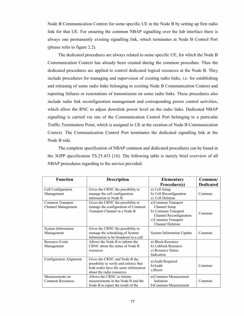
77
Node B Communication Context for some specific UE in the Node B by setting up first radio
link for that UE. For ensuring the common NBAP signalling over the Iub interface there is
always one permanently existing signalling link, which terminates at Node B Control Port
(please refer to figure 2.2).
The dedicated procedures are always related to some specific UE, for which the Node B
Communication Context has already been created during the common procedure. Thus the
dedicated procedures are applied to control dedicated logical resources at the Node B. They
include procedures for managing and supervision of existing radio links, i.e. for establishing
and releasing of some radio links belonging to existing Node B Communication Context and
reporting failures or restorations of transmission on some radio links. These procedures also
include radio link reconfiguration management and corresponding power control activities,
which allow the RNC to adjust downlink power level on the radio links. Dedicated NBAP
signalling is carried via one of the Communication Control Port belonging to a particular
Traffic Termination Point, which is assigned to UE at the creation of Node B Communication
Context. The Communication Control Port terminates the dedicated signalling link at the
Node B side.
The complete specification of NBAP common and dedicated procedures can be found in
the 3GPP specification TS.25.433 [16]. The following table is merely brief overview of all
NBAP procedures regarding to the service provided.
Function Description Elementary Procedure(s)
Common/Dedicated
Cell Configuration Management
Gives the CRNC the possibility to manage the cell configuration information in Node B
a) Cell Setup b) Cell Reconfiguration c) Cell Deletion
Common
Common Transport Channel Management
Gives the CRNC the possibility to manage the configuration of Common Transport Channel in a Node B
a) Common Transport Channel Setup
b) Common Transport Channel Reconfiguration
c) Common Transport Channel Deletion
Common
System Information Management
Gives the CRNC the possibility to manage the scheduling of System Information to be broadcast in a cell
System Information Update Common
Resource Event Management
Allows the Node B to inform the CRNC about the status of Node B resources
a) Block Resource b) Unblock Resource c) Resource Status Indication
Configuration Alignment Gives the CRNC and Node B the possibility to verify and enforce that both nodes have the same information about the radio resources.
a) Audit Required b) Audit c) Reset
Common
Measurements on Common Resources
Allows the CRNC to initiate measurements in the Node B and the Node B to report the result of the
a) Common Measurement Initiation
b)Common Measurement Common

78
measurements. Reporting c) Common Measurement
Termination d) Common Measurement
Failure Common Radio Link Management Allows the CRNC to manage radio
links using dedicated resources in a Node B
a) Radio Link Setup b) Radio Link Addition c) Radio Link Deletion d) Unsynchronized Radio
Link Reconfiguration e) Synchronized Radio Link
Reconfiguration Preparation
f) Synchronized Radio Link Reconfiguration Commit
g) Synchronized Radio Link Reconfiguration Cancellation
h) Radio Link Pre-emption
Dedicated
Radio Link Supervision Allows the CRNC to report failures and restorations of a Radio Link.
a) Radio Link Failure b) Radio Link Restoration Dedicated
Measurements on Dedicated Resources
Allows the CRNC to initiate measurements on dedicated resources in the Node B and the Node B to report the result of the measurements.
a) Dedicated Measurement Initiation
b) Dedicated Measurement Reporting
c) Dedicated Measurement Termination
d) Dedicated Measurement Failure
Dedicated
DL Power Drifting Correction
Allows the CRNC to adjust the DL power level of one or more Radio Links in order to avoid DL power drifting between the Radio Links.
Downlink Power Control Dedicated
Reporting of General Error Situations
Allows reporting of general error situations, for which function specific error messages have not been defined.
Error Indication Common / Dedicated
Table 3.3. Mapping between NBAP functions and elementary procedures
The Transport Resource Management in not explicitly mentioned in this table but its
tasks indirectly present in some procedures, e.g. in Radio Link Setup procedure which is
described in the following subsection.
3.5.2 Example of signalling procedure
As it was stated above the functionality of NBAP and its services are defined in terms
of elementary procedures. It can be said that the elementary procedure is defined as a unit of
interaction between two NBAP peer entities.
All procedures are executed in the following manner. Each procedure is triggered by the
message sent from the radio network management unit of the RNC or control unit of Node B.
Upon receiving trigger message the initiating peer entity forms the initiating PDU, encodes it
79
and pass it down to the transport layers to be transferred across the Iub interface. Receiving
peer entity decodes PDU, analyses its content and based on it generates and forward some
request to the corresponding interfacing unit. At this point if the given procedure consists only
of initiating message without response it is considered completed. Otherwise the receiving
NBAP entity awaits for a response from the interfacing unit, based on which it generates
corresponding PDU, encodes and forwards across the Iub interface back to the initiating
entity. The initiating entity decodes response PDU and forwards the confirmation message to
the unit, which triggered the given elementary procedure.
From the point of problem domain studied in this thesis the best way to illustrate the
contribution of NBAP protocol in performing the Transport Resource Management over Iub
interface is to examine the signalling involved in the dedicated user plane connection
establishment to a UE. Such kind of signalling procedure involves a lot of interaction between
different network elements and signalling protocols. For simplicity the example is limited
within the Iub Radio Network and Transport Network control planes, the other interfaces are
left out of scope.
For describing the interaction between protocols the Message Sequence Charts (MSCs)
notation is used. Following this notation the interacting protocols are shown as ellipses on the
each side of the interface. The messages traversing across the interface are depicted as the
named arrows. It should be noted that in MSC the messages are sent and received in the
sequential order. Meaning that at any given moment of time only one message in transferred
between two peer entities in order defined in the MSC, from top to down.
Besides the Iub interface protocols the presented example includes the RRC signalling.
This is done in effort to present more or less clear picture about who and why from the
operational environment triggers Iub control plane protocols to setup dedicated connection
over Iub. The RRC is the protocol, which carries out the communication between RNC and
UE. This protocol is used by the UE to inform RNC that it needs a dedicated connection
(when making a call for example) and deliver the parameters of the required connection
(transparently to Node B). When the connection has been established, the RNC in turn use the
RRC protocol to inform the UE about the characteristics of allocated dedicated channel.
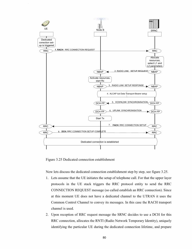
80
Figure 3.25 Dedicated connection establishment
Now lets discuss the dedicated connection establishment step by step, see figure 3.25.
1. Lets assume that the UE initiates the setup of telephone call. For that the upper layer
protocols in the UE stack triggers the RRC protocol entity to send the RRC
CONNECTION REQUEST message (so called establish an RRC connection). Since
at this moment UE does not have a dedicated channel to the UTRAN it uses the
Common Control Channel to convey its messages. In this case the RACH transport
channel is used.
2. Upon reception of RRC request message the SRNC decides to use a DCH for this
RRC connection, allocates the RNTI (Radio Network Temporary Identity), uniquely
identifying the particular UE during the dedicated connection lifetime, and prepare
1. RACH: RRC CONNECTION REQUEST
Node B SRNCUE
Dedicated conection set- up is triggered
RRC
RRC RRC
NBAPNBAP 2. RADIO LINK SETUP REQUEST
Activate resources,start Rx
NBAP NBAPRADIO LINK SETUP RESPONSE
ALCAP Iub Data Transport Bearer setup
DCH FP DCH FP
DCH FP DCH FP
DOWNLINK SYNCHRONISATION
UPLINK SYNCHRONISATION
Start Tx
RRC
RRC RRC
FACH: RRC CONNECTION SETUP
DCH: RRC CONNECTION SETUP COMPLETE
Allocateresources,
select L1 andL2 parameters
Dedicated connection is established
RNC
3.
4.
5.
6.
7.
8.
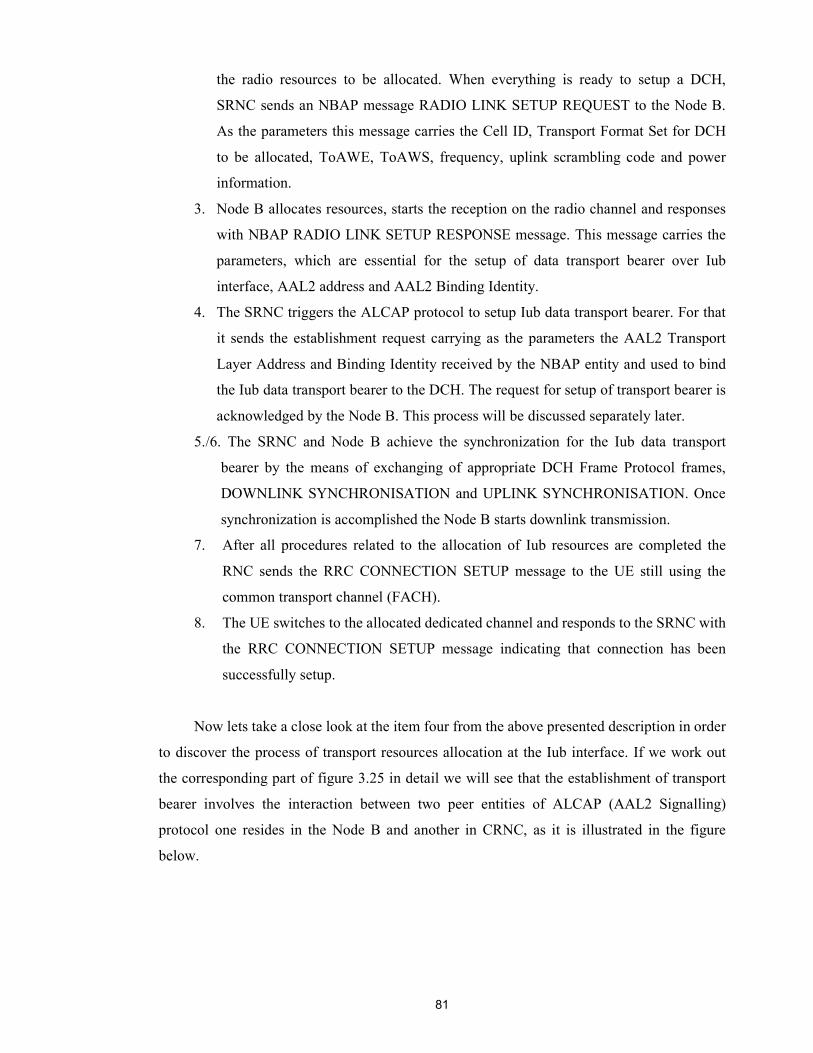
81
the radio resources to be allocated. When everything is ready to setup a DCH,
SRNC sends an NBAP message RADIO LINK SETUP REQUEST to the Node B.
As the parameters this message carries the Cell ID, Transport Format Set for DCH
to be allocated, ToAWE, ToAWS, frequency, uplink scrambling code and power
information.
3. Node B allocates resources, starts the reception on the radio channel and responses
with NBAP RADIO LINK SETUP RESPONSE message. This message carries the
parameters, which are essential for the setup of data transport bearer over Iub
interface, AAL2 address and AAL2 Binding Identity.
4. The SRNC triggers the ALCAP protocol to setup Iub data transport bearer. For that
it sends the establishment request carrying as the parameters the AAL2 Transport
Layer Address and Binding Identity received by the NBAP entity and used to bind
the Iub data transport bearer to the DCH. The request for setup of transport bearer is
acknowledged by the Node B. This process will be discussed separately later.
5./6. The SRNC and Node B achieve the synchronization for the Iub data transport
bearer by the means of exchanging of appropriate DCH Frame Protocol frames,
DOWNLINK SYNCHRONISATION and UPLINK SYNCHRONISATION. Once
synchronization is accomplished the Node B starts downlink transmission.
7. After all procedures related to the allocation of Iub resources are completed the
RNC sends the RRC CONNECTION SETUP message to the UE still using the
common transport channel (FACH).
8. The UE switches to the allocated dedicated channel and responds to the SRNC with
the RRC CONNECTION SETUP message indicating that connection has been
successfully setup.
Now lets take a close look at the item four from the above presented description in order
to discover the process of transport resources allocation at the Iub interface. If we work out
the corresponding part of figure 3.25 in detail we will see that the establishment of transport
bearer involves the interaction between two peer entities of ALCAP (AAL2 Signalling)
protocol one resides in the Node B and another in CRNC, as it is illustrated in the figure
below.
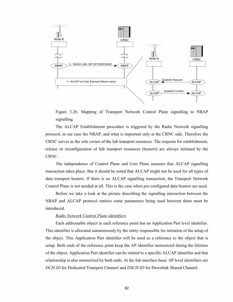
82
Figure 3.26. Mapping of Transport Network Control Plane signalling to NBAP
signalling.
The ALCAP Establishment procedure is triggered by the Radio Network signalling
protocol, in our case the NBAP, and what is important only at the CRNC side. Therefore the
CRNC serves as the sole owner of the Iub transport resources. The requests for establishment,
release or reconfiguration of Iub transport resources (bearers) are always initiated by the
CRNC.
The independence of Control Plane and User Plane assumes that ALCAP signalling
transaction takes place. But it should be noted that ALCAP might not be used for all types of
data transport bearers. If there is no ALCAP signalling transaction, the Transport Network
Control Plane is not needed at all. This is the case when pre-configured data bearers are used.
Before we take a look at the picture describing the signalling interaction between the
NBAP and ALCAP protocol entities some parameters being used between them must be
introduced.
Radio Network Control Plane identifiers
Each addressable object in each reference point has an Application Part level identifier.
This identifier is allocated autonomously by the entity responsible for initiation of the setup of
the object. This Application Part identifier will be used as a reference to the object that is
setup. Both ends of the reference point keep the AP identifier memorized during the lifetime
of the object. Application Part identifier can be related to a specific ALCAP identifier and that
relationship is also memorized by both ends. At the Iub interface basic AP level identifiers are
DCH-ID for Dedicated Transport Channel and DSCH-ID for Downlink Shared Channel.
NBAP NBAPRADIO LINK SETUP RESPONSE
ALCAP Iub Data Transport Bearer setup
3.
4.
Node B СRNC
RNC
ALCAPEstablish Request
Node B СRNC
RNC
ALCAP
ALCAPEstablish Confirm
ALCAP

83
Transport Network Control Plane identifiers
ALCAP identifier is used only in Transport Network Control plane (ALCAP) and may
be used in User Plane in the actual data transmission using the transport link. ALCAP
identifier identifies the transport link according to the naming conventions defined for the
transport link type in question. Both ends of the reference point of the ALCAP keeps the
ALCAP identifier memorized during the lifetime of the transport link. Each ALCAP identifier
can be binded to an Application Part identifier. The example of ALCAP identifier for the
AAL2 transmission link is AAL2 Path ID together with CID.
Binding identifier
Binding Identifier (Binding ID) is used to initialize the linkage between ALCAP and
Application Part (NBAP) identifiers. Binding identifier can be used both in Radio Network
Control plane Application Part protocols and in Transport Network Control Plane ALCAP
protocol.
Binding ID binds the Radio and Transport Network Control plane identifiers together.
To ensure maximal independence of those two planes, the binding ID is used only when
necessary, i.e. only in Radio Network Control plane Application Part messages in which a
new association between the planes is created and in ALCAP messages creating new transport
bearers.
It should be noted that Binding ID for each transport bearer is allocated before the setup
of that transport bearer, i.e. before the ALCAP signalling transaction takes place. In case of
Iub interface the Binding ID is allocated at the Node B and sent on one direction using the
NBAP protocol (in response message) and is returned in the other direction by the ALCAP
protocol. So that the Binding ID has already been assigned and tied to a radio application
procedure when the first ALCAP message is received in a node.
The association between the connection Id in the Application Part (NBAP) protocol
(e.g. identifying a RAB) and the corresponding connection Id in the ALCAP protocol (e.g.
identifying the AAL2 channel for that RAB) that was created with the help of Binding ID is
memorized by both peers of each reference point and kept for the lifetime of the
corresponding transport bearer.
The Binding ID may be released and re-used as soon as both the NBAP procedure and
the ALCAP procedure that used it are completed in both peers of the reference point.
The following figures illustrate how the NBAP and ALCAP instances are linked
together via the Binding Identifier in the data transport bearer setup phase.
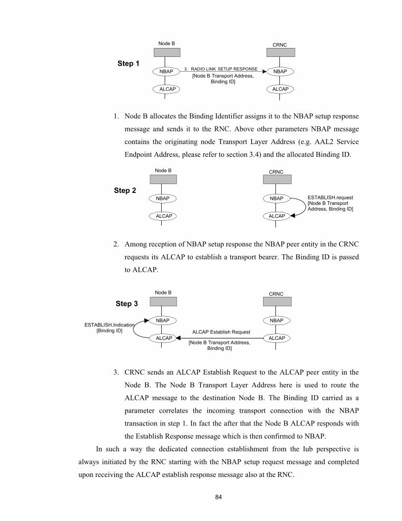
84
1. Node B allocates the Binding Identifier assigns it to the NBAP setup response
message and sends it to the RNC. Above other parameters NBAP message
contains the originating node Transport Layer Address (e.g. AAL2 Service
Endpoint Address, please refer to section 3.4) and the allocated Binding ID.
2. Among reception of NBAP setup response the NBAP peer entity in the CRNC
requests its ALCAP to establish a transport bearer. The Binding ID is passed
to ALCAP.
3. CRNC sends an ALCAP Establish Request to the ALCAP peer entity in the
Node B. The Node B Transport Layer Address here is used to route the
ALCAP message to the destination Node B. The Binding ID carried as a
parameter correlates the incoming transport connection with the NBAP
transaction in step 1. In fact the after that the Node B ALCAP responds with
the Establish Response message which is then confirmed to NBAP.
In such a way the dedicated connection establishment from the Iub perspective is
always initiated by the RNC starting with the NBAP setup request message and completed
upon receiving the ALCAP establish response message also at the RNC.
NBAP NBAP RADIO LINK SETUP RESPONSE3.
Node B СRNC
ALCAP ALCAP
Step 1 [Node B Transport Address,
Binding ID]
NBAP NBAP
Node B СRNC
ALCAP ALCAP
Step 2 ESTABLISH.request [Node B Transport Address, Binding ID]
NBAP NBAP
Node B СRNC
ALCAP ALCAP
Step 3
[Node B Transport Address, Binding ID]
ALCAP Establish RequestESTABLISH.Indication
[Binding ID]
85
In addition the above presented example shows how the NBAP Radio Link Setup
procedure contributes to the Transport Resource Management tasks, particularly to the
transport bearer setup. Another example can be the NBAP Radio Link Reconfiguration
procedure that assures the transport bearer replacement. This activity takes place, for example
during handling the Softer Handover case, when the user moves to another cell belonging to
the same Node B and there is a need to establish a new connection through that new cell.
In this case the transport bearer replacement can be achieved by using the Synchronized
Radio Link Reconfiguration Preparation procedure in combination with the Synchronized
Radio Link Reconfiguration Commit procedure, or by using the Unsynchronized Radio Link
Reconfiguration procedure. In both cases the following steps can be discerned:
1) The new transport bearer is established (using the same ALCAP transactions as
presented above) after which two transport bearers exist in parallel.
2) The transport channel(s) is/are switched to the new transport bearer.
3) The old transport bearer is released.
In step 1), communication on the old transport bearer continues as normal. In addition,
the Node B conducts the Synchronization procedure on the new bearer. This enables the
SRNC to determine the timing on the new transport bearer.
Regarding step 2), the moment of switching is determined differently in the
synchronized and unsynchronized case:
When using the combination of the Synchronized Radio Link Reconfiguration
Preparation procedure and the Synchronized Radio Link Reconfiguration Commit procedure,
the UL/DL data frames are transported on the new transport bearer from the CFN (Connection
Frame Number) indicated in the RL RECONFIGURATION COMMIT message.
When using the Unsynchronized Radio Link Reconfiguration procedure, the Node-B
starts using the new transport bearer for the transport of UL data frames from the CFN at
which the new transport bearer is considered synchronized.
In both cases, starting from this CFN the Node B executes all applicable DCH frame
protocol procedures on the new transport bearer.
And finally in step 3), the old transport bearer is released (using ALCAP Release
procedure).
86
4. IMPLEMENTATION OF NBAP AND NODE B MANAGER
In this chapter we describe the practical part of the thesis. That is how the NBAP
protocol and NBM (Node B Manager) functional unit were implemented as a part of ongoing
Nokia Research Center project. The discussion includes the general background information
about the project and overview of the NBAP and NBM implementation. Since the
implementation involves a lot of tools and techniques their descriptions are also presented in
this chapter.
As a practical part of the thesis the NBAP protocol and NBM were newly implemented
according to open 3GPP technical specification 25.433 release 4.1. However a lot of
experience was borrowed from the NBAP and NBM implementations that were done
according to Nokia internal specifications within the framework of the same Nokia Research
Center project. Above all the addition functionality were added to the NBAP as well as NBM
implementations aimed to provide with the Transport Resource Management services.
4.1 General information and development stages
Implementation of NBAP and NBM discussed in this chapter is used in the software
package that models the whole stack of UMTS signalling protocols. This software package
consists of executable SDL models organized in the executable library called 3G SDL
Library. The main objective of this library is to provide other ongoing Nokia projects with the
up-to-date implemented protocols, so that they can be reused as a ready components in the
projects that they deal with, for example, testing of different UMTS network elements. For
instance the described NBAP implementation is used in the Node B testing project, as well as
in the RNC tester. Since new versions of 3GPP specifications are released quite frequently, as
they moving from the R99 towards R5, (basically once in 4 months) another important
responsibility of the 3G SDL project is to keep all protocol implementations up-to-date. This
constitutes the continuous character of the project. On the other hand the 3G SDL project
influence on the standardization process itself. This is because there are still not many
implementations of the 3G systems realized in practice (one commercial network is deployed
in Tokyo and another test network is running on the island Mann). Therefore nobody can
guarantee that the standardized protocols are really feasible. And this is what is also examined
in our project, whether the specifications really work or not. The feedback provided by the
project is considered in the following releases.
In fact the 3G SDL project is running as a general software development project, since
the protocol development is the particular case of the software engineering process. The
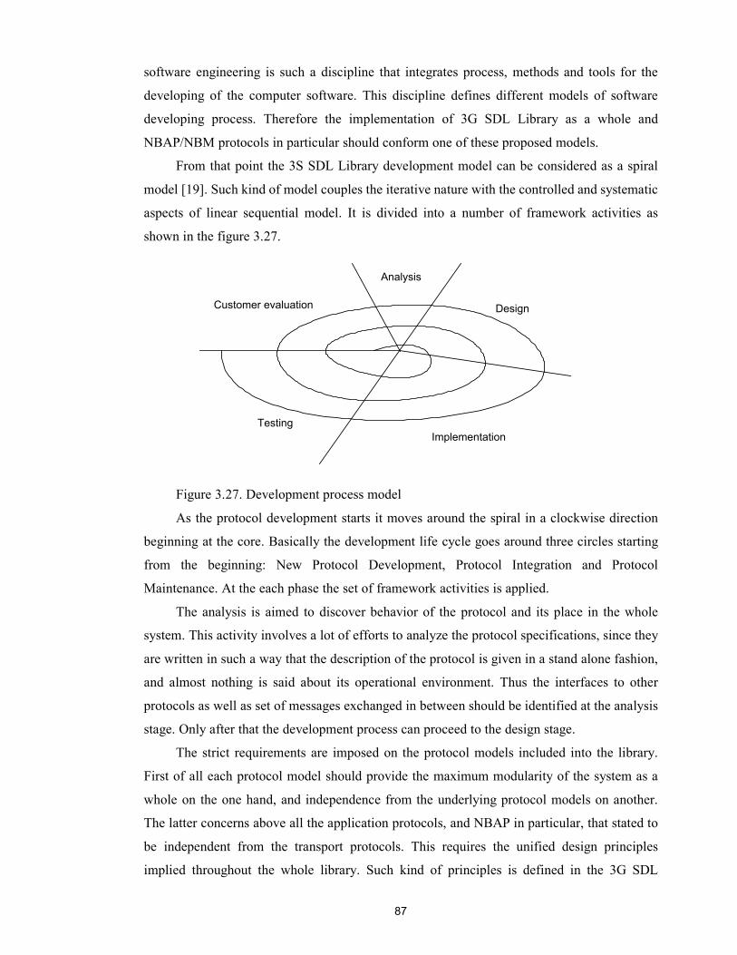
87
software engineering is such a discipline that integrates process, methods and tools for the
developing of the computer software. This discipline defines different models of software
developing process. Therefore the implementation of 3G SDL Library as a whole and
NBAP/NBM protocols in particular should conform one of these proposed models.
From that point the 3S SDL Library development model can be considered as a spiral
model [19]. Such kind of model couples the iterative nature with the controlled and systematic
aspects of linear sequential model. It is divided into a number of framework activities as
shown in the figure 3.27.
Figure 3.27. Development process model
As the protocol development starts it moves around the spiral in a clockwise direction
beginning at the core. Basically the development life cycle goes around three circles starting
from the beginning: New Protocol Development, Protocol Integration and Protocol
Maintenance. At the each phase the set of framework activities is applied.
The analysis is aimed to discover behavior of the protocol and its place in the whole
system. This activity involves a lot of efforts to analyze the protocol specifications, since they
are written in such a way that the description of the protocol is given in a stand alone fashion,
and almost nothing is said about its operational environment. Thus the interfaces to other
protocols as well as set of messages exchanged in between should be identified at the analysis
stage. Only after that the development process can proceed to the design stage.
The strict requirements are imposed on the protocol models included into the library.
First of all each protocol model should provide the maximum modularity of the system as a
whole on the one hand, and independence from the underlying protocol models on another.
The latter concerns above all the application protocols, and NBAP in particular, that stated to
be independent from the transport protocols. This requires the unified design principles
implied throughout the whole library. Such kind of principles is defined in the 3G SDL
Analysis
Design
Implementation
Customer evaluation
Testing
88
Library Style Guide that is strictly followed during the design and implementation stages for
all protocols in the library. Besides this the protocol model should be designed in such a way
that is would allow easy updating to the new specifications by simply adding new
functionality without extensive revision of its architecture.
In fact the protocol design can be seen as splitted into two parts: definition of the
external interfaces towards the protocol operational environment, and constructing the internal
protocol architecture. Then the implementation task is merely to fill the skeleton created at the
design stage with the appropriate logic and signalling procedures. Since the protocols are
event driven systems, meaning that most of their actions are triggered by the external events,
the definition of external interfaces is the most important and crucial aspect of the design
stage.
Today, it is widely accepted that a key to success of a system lies in a thorough and
rigorous specification and design. This requires the use of formal description techniques
allowing the system to be specified at different abstraction levels, beginning from an
overview and going on to very specific details. As one of these methods the Specification and
Description Language (SDL) is used in the project. This language is widely used in the
developing of communication systems, real-time and complex distributed systems. Though
originally the SDL was seen as a language for the system design, at the implementation stage
it can be easily converted into code in a particular programming language, such of C or C++.
Several tools that offer such translation features are available today. One of them, the
Telelogic SDL Design Tool, is being used in our project.
Besides that the implementation of the protocols is usually done regardless to the
executable environment in which they will perform. This is due to the basic principle of
protocol software serving as a mean for communication between different systems, which in
general may be of different, heterogeneous nature. For example each intercommunicating
node (network) may have data representation its own. In order to avoid network data
representation and design problems the design of application data or PDUs, which are
transmitted through the network should be done at abstract data type level. The solution here
is to use the high-level specification language for expressing the abstract syntax of application
data. In our project one of such data specification languages, Abstract Syntax Notation One
(ASN.1) is used.
The NBAP as well as other protocol models in the library are implemented in SDL
using the Telelogic Tau SDL Design Tool (SDT) as a development environment. The SDT is
a commercial product provided by the Swedish company Telelogic [87] and widely used
89
within the telecommunication companies worldwide. It provides the means for writing SDL
code, generation the C code and finally building the executable model.
While the SDL language is used to define the dynamic behavior of the system, the data
structures used in protocol model are defined using the ASN.1 language. There is a number of
so called CASN-tools employed in the project. Their task is to provide bridge between ASN.1
definitions and SDT, allowing the use of ASN.1 data types in SDL code. CASN-tools are
developed in the Nokia Research Center and thus are property of NRC.
After the SDL model is created and analyzed against the errors the executable model is
then built. For that some part of hand written C code allowing encoding/decoding of PDUs
must be added at the compilation phase.
In fact the implementation phase is done in the iterative manner alternating with the
testing. It means that during the implementation as new feature is added the model is built
tested and validated. Such kind of approach allows to uncover possible bugs at the point while
the system is not yet huge, and can be tested easier.
Once the complete system is finally built and thoroughly tested is it integrated into the
library and the integration testing is performed. The integration means that all the protocols
are connected together forming the UMTS protocol stack. As soon as the integration phase is
passed successfully the whole library or it is particular protocols are delivered to the
customers. At this point the role of the customers in software engineering process is to
provide a feedback based on the product evaluation. The customer feedback is vary valuable
for the project, since it allows developers better adjust protocol models to the customer's
requirements for the further releases.
4.2 Development environment
SDL
The Specification and Description Language (SDL) is a standard formal language
developed by the International Telecommunication Union – Telecommunications (ITU-T) to
specify and describe distributed and event driven real-time systems. Originally it was intended
mainly for specification purposes but as time went by the new features like object-oriented
support and combined use of SDL with ASN.1 were added and now it is widely used like any
other high-level programming language.
The SDL covers all areas of system developing from the static system architecture to its
dynamic behavior. This is achieved by different levels of abstraction provided by SDL. The
system under specification is decomposed into four main hierarchical levels: system, block,
process and procedure. The system is the topmost level. It consists of one or several blocks,
which in turn incorporate one or several processes. In such a way the system and block
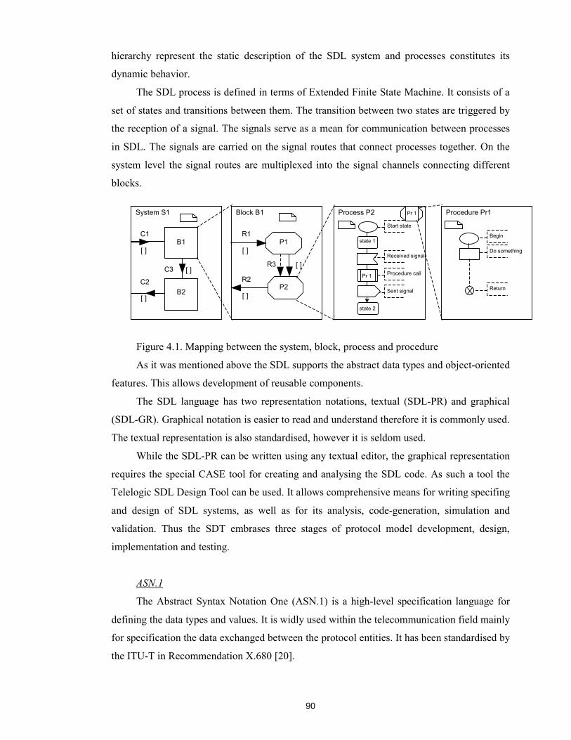
90
hierarchy represent the static description of the SDL system and processes constitutes its
dynamic behavior.
The SDL process is defined in terms of Extended Finite State Machine. It consists of a
set of states and transitions between them. The transition between two states are triggered by
the reception of a signal. The signals serve as a mean for communication between processes
in SDL. The signals are carried on the signal routes that connect processes together. On the
system level the signal routes are multiplexed into the signal channels connecting different
blocks.
Figure 4.1. Mapping between the system, block, process and procedure
As it was mentioned above the SDL supports the abstract data types and object-oriented
features. This allows development of reusable components.
The SDL language has two representation notations, textual (SDL-PR) and graphical
(SDL-GR). Graphical notation is easier to read and understand therefore it is commonly used.
The textual representation is also standardised, however it is seldom used.
While the SDL-PR can be written using any textual editor, the graphical representation
requires the special CASE tool for creating and analysing the SDL code. As such a tool the
Telelogic SDL Design Tool can be used. It allows comprehensive means for writing specifing
and design of SDL systems, as well as for its analysis, code-generation, simulation and
validation. Thus the SDT embrases three stages of protocol model development, design,
implementation and testing.
ASN.1
The Abstract Syntax Notation One (ASN.1) is a high-level specification language for
defining the data types and values. It is widly used within the telecommunication field mainly
for specification the data exchanged between the protocol entities. It has been standardised by
the ITU-T in Recommendation X.680 [20].
System S1
C1 B1
[ ]
Block B1 Procedure Pr1 Process P2
state 1
C2
[ ]
C3 [ ]
B2
R1
[ ]
R2
[ ]
R3 [ ]
P2
P1
Pr 1
state 2
Pr 1
Start state
Received signal
Procedure call
Sent signal
Begin
Do something
Return

91
The main idea behind the ASN.1 is to represent information independently from the
transfer syntax, i.e. the way how the information is represented on a particular platform.
Therefore the ASN.1 operates with the abstract syntaxes saying nothing about their local
representation. For example if the ASN.1 defines some type of INTEGER. In fact it imposes
no restriction on the value the instance of this type may have. Such kind of restriction are
platform dependent and hence shall not affect on the abstract syntax. In other aspects the
ASN.1 is similar to any other modern definition language.
ASN.1 has tree main language constructs, types, values and modules. The type notation
is defined as follows: typereference ::= notation for the type, where the notation for the type
can be the one of the built-in type (such as INTEGER) or the type constructor for defining
more complex types. The value notation represents the instantiation of the existing type. The
example relation between type and value notation is shown in the following figure.
Figure 4.2 The example of ASN.1 value definition
For convertion of ASN.1 values to the transfer format there is the encoding rules
accosiated with ASN.1. They perform the exact translation of universal ASN.1 value to the
particular transfer syntax, which will be then transferred over the communication medium. As
one of such encoding rules the Packet Encoding Rules (PER) is used in the project. PER is
standardized by the ITU-T in recommendation X.691 [18].
On the sending side the encoding functions based on PER codec accept as input the
ASN.1 value of some type, for example like presented above, and returns as output the frame
represented by a bit string. Such operation is called encoding. In the form of bit string the
information is suitable for segmentation on the transport level and transferring over the
communication media. On the receiving side the inverse operation is performed. The
assembled at transport layer frame is decoded using the PER decoding functions and receiving
protocol entity gets the original ASN.1 value.
As in case of SDL the ASN.1 has support of wide range of tools providing the
functionality from the syntax and semantic check of ASN.1 definitions to the SDL and C code
ASN.1 value definition NbapNbAuditResponse : { end-Of-Audit-Sequence-Indicator not-end-of-audit-sequence, cell-InformationList-AuditRsp { { c-ID 3, configurationGenerationID 1, resourceOperationalState disabled, availabilityStatus in-test, local-Cell-ID 3 } }, transactionID 4 }
ASN.1 type definition NbapNbAuditResponse ::= SEQUENCE { end-Of-Audit-Sequence-Indicator End-Of-Audit-Sequence-ndicator , cell-InformationList-AuditRsp Cell-Information-AuditRsp , transactionID INTEGER }-
92
generation. As such kind of tools the Nokia in-house ASN.1 tools were used in the project.
Their brief description is given below.
CASN
CASN stands for Compiler for ASN.1. It serves as a common front-end for all other
ASN.1 tools. It checks the ASN.1 definitions for errors and if none generates an internal
binary representation in the form of syntax tree for the back-ends.
ASN2C
ASN2C is a one of back-ends for the CASN compiler. It generates C type definitions
from the ASN.1 data types and C constants for simple values, named numbers and bits.
Optionally it may also provide the support for BER codec by generating BER
encoding/decoding functions. BER stands for Basic Encoding Rules, they can be used as an
alternative to PER. Besides ASN2C can also generate the test functions for asking and
printing values. As input the tool accept the syntax tree file from CASN and as output it
produces a number of C files. For example for ASN.1 module NBAP_PDUs the following
files may be generated: C types definitions <nbap_pdus.typ>, C constants and macros
<nbap_pdus.def>, C test functions prototypes <nbap_pdustst.ext> C test functions definitions
<nbap_pdustst.c>.
ASN2PER
ASN2PER is another back-end for the CASN compiler. It generates the PER
encoding/decoding functions for the ASN2C generated C types. They are used for coding of
NBAP PDUs as it was described earlier. In addition to ASN2C compilation result the
ASN2PER generates three more files: PER C encoding/decoding function prototypes
<nbap_pdusper.ext>, PER C encoding functions definitions <nbap_pduspec.c> and PER C
decoding functions definitions <nbap_pduspdc.c>.
ASN4SDT
ASN4SDT is the third back-end for CASN compiler that was used in the project. It
generates the SDL sorts from the ASN.1 type definitions, so that they can be used in the SDL
model. Besides this it generates a C glue-code combining the C code generated by previous
ASN.1 tools and by Telelogic SDT. As compilation results we get: the SDL type definitions
<nbap_pdus.sdl>, glue-code supporting functions prototypes <nbap_pdussdt.h> and glue-
code supporting functions definitions <nbap_pdussdt.c>.
In such a way after running all ASN.1 tools for each ASN.1 module (defined in the file
<module>.asn) the one receives about ten different files (in fact the number of generated files
depends on the tool configuration) containing the C code that can be further compiled in
linked into the executable model. The overall process of making the executable protocol
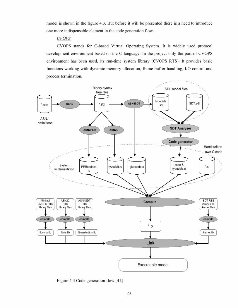
93
model is shown in the figure 4.3. But before it will be presented there is a need to introduce
one more indispensable element in the code generation flow.
CVOPS
CVOPS stands for C-based Virtual Operating System. It is widely used protocol
development environment based on the C language. In the project only the part of CVOPS
environment has been used, its run-time system library (CVOPS RTS). It provides basic
functions working with dynamic memory allocation, frame buffer handling, I/O control and
process termination.
Figure 4.3 Code generation flow [41]
Compile
*.asn CASN ASN4SDT
ASN2PER ASN2C
*.stxtypedefs
.sdl
SDT Analyser
Code generator
Link
MinimalCVOPS RTSlibrary files
*.o
ASN2CRTS
library files
ASN4SDTRTS
library files
libcvrts.lib librts.lib libasn4sdtrts.lib
compile compile compile
SDT RTSlibrary filed,kernel files
kernel.lib
compile
ASN.1definitions
Binary syntaxtree files
SDL model files
Hand writtenown C code
SDT.sdl
typedefs.cPERcodecs.c
gluecode.c code &typedefs.c *.cSystem
implementation
Executable model
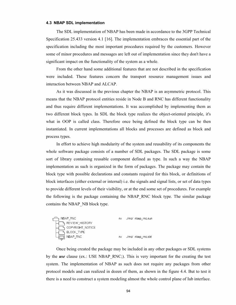
94
4.3 NBAP SDL implementation
The SDL implementation of NBAP has been made in accordance to the 3GPP Technical
Specification 25.433 version 4.1 [16]. The implementation embraces the essential part of the
specification including the most important procedures required by the customers. However
some of minor procedures and messages are left out of implementation since they don't have a
significant impact on the functionality of the system as a whole.
From the other hand some additional features that are not described in the specification
were included. These features concern the transport resource management issues and
interaction between NBAP and ALCAP.
As it was discussed in the previous chapter the NBAP is an asymmetric protocol. This
means that the NBAP protocol entities reside in Node B and RNC has different functionality
and thus require different implementations. It was accomplished by implementing them as
two different block types. In SDL the block type realizes the object-oriented principle, it's
what in OOP is called class. Therefore once being defined the block type can be then
instantiated. In current implementations all blocks and processes are defined as block and
process types.
In effort to achieve high modularity of the system and reusability of its components the
whole software package consists of a number of SDL packages. The SDL package is some
sort of library containing reusable component defined as type. In such a way the NBAP
implementation as such is organized in the form of packages. The package may contain the
block type with possible declarations and constants required for this block, or definitions of
block interfaces (either external or internal) i.e. the signals and signal lists, or set of data types
to provide different levels of their visibility, or at the end some set of procedures. For example
the following is the package containing the NBAP_RNC block type. The similar package
contains the NBAP_NB block type.
Once being created the package may be included in any other packages or SDL systems
by the use clause (ex.: USE NBAP_RNC;). This is very important for the creating the test
system. The implementation of NBAP as such does not require any packages from other
protocol models and can realized in dozen of them, as shown in the figure 4.4. But to test it
there is a need to construct a system modeling almost the whole control plane of Iub interface.

95
This is required to see how the NBAP messages traverse from one side of interface to another.
To ensure this the test system may require the modeling of the whole NBAP operational
environment, that results in using about forty additional packages from other protocols.
Figure 4.4 NBAP software package
Such kind of test system is depicted in the figure 4.5. From the highest level of
abstraction it consists of two blocks NodeB and RNC representing corresponding UTRAN
elements. The system is called NBAP_NBM_ALCAP. It means that these three protocol
models are connected within the system and all other protocols lay beyond. The interaction
with them is carried through the system's external interfaces. These interfaces are: towards
Radio Network Management unit at the RNC side, to the physical layer and towards the RRC
protocol at the Node B side.
The subsequent decomposition of the NodeB and RNC blocks uncover the following
structure (see figure 4.5). Both blocks contain the NBAP protocol entities as such, signalling
transport protocol emulators (FCL) and ALCAP protocol entities. Beside this the NodeB
block contains the Node B Manager unit (NBM) which is described in the next section. All
protocol entities are implemented as block types, and instantiated in the NodeB and RNC
blocks.
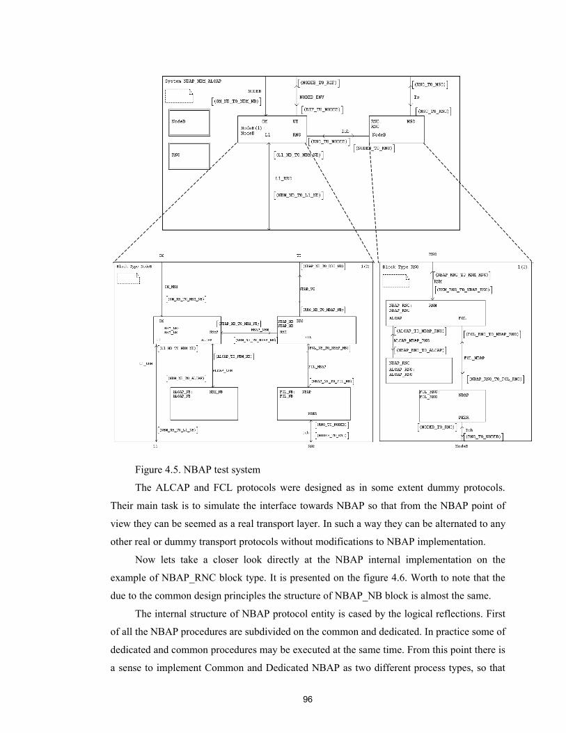
96
Figure 4.5. NBAP test system
The ALCAP and FCL protocols were designed as in some extent dummy protocols.
Their main task is to simulate the interface towards NBAP so that from the NBAP point of
view they can be seemed as a real transport layer. In such a way they can be alternated to any
other real or dummy transport protocols without modifications to NBAP implementation.
Now lets take a closer look directly at the NBAP internal implementation on the
example of NBAP_RNC block type. It is presented on the figure 4.6. Worth to note that the
due to the common design principles the structure of NBAP_NB block is almost the same.
The internal structure of NBAP protocol entity is cased by the logical reflections. First
of all the NBAP procedures are subdivided on the common and dedicated. In practice some of
dedicated and common procedures may be executed at the same time. From this point there is
a sense to implement Common and Dedicated NBAP as two different process types, so that

97
their instances may run simultaneously. In such a way corresponding
NBAP_RNC_COMMON and NBAP_RNC_UEC processes emerge. In addition the division
into process types pretty much conforms to the way how the RNS is seen from the CRNC,
when there are several Node Bs belonging to it, each represented by a
NBAP_RNC_COMMON process, and a number of UE connections established through the
given CRNC, each connection is represented by NBAP_RNC_UEC process. It is obvious that
there can be multiple UE connections need to be controlled at the same time. This results in
the solution where NBAP_RNC_UEC may have several instances dynamically created for
each UE connection. At this point appears the need for the routing between different process
instances and for managing their dynamic creation and destroying. For this purposes the third
process type was defined, the NBAP_RNC_RED.
Figure 4.6 Structure of NBAP_RNC block type
So then, the process NBAP_RNC_COMMON executes all common NBAP procedures
not related to a particular UE, as it was discussed in the previous chapter. There can be from
zero upto the certain number (defined by the constant C_NR_OF_NODEBS) of
NBAP_RNC_COMMON processes. They are dynamically created by the NBAP_RNC_RED
process on request from the RNM unit. Therefore the logical meaning of the
NBAP_RNC_COMMON process is that each process instance represents one Node B
belonging to the given RNC. The process has only unidirectional signal routes to the
environment. This is due to the basic design concept stating that the all incoming signals from
the environment are handled via the RED process [45]. The COMMON, as well as UEC,
process can only send signals to the environment, and moreover only those that don't require
encoding. For the routing between multiple instances of the NBAP_RNC_COMMON
processes the RED process stores the routing table in form of array of PIDs indexed by the
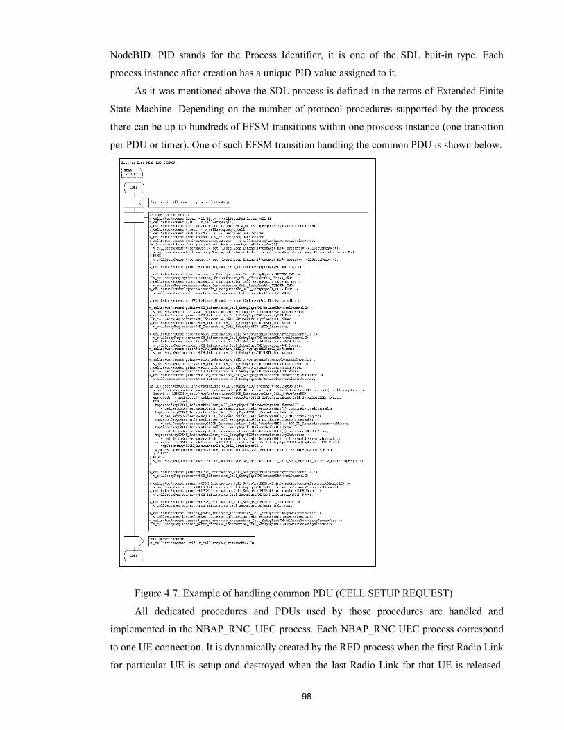
98
NodeBID. PID stands for the Process Identifier, it is one of the SDL buit-in type. Each
process instance after creation has a unique PID value assigned to it.
As it was mentioned above the SDL process is defined in the terms of Extended Finite
State Machine. Depending on the number of protocol procedures supported by the process
there can be up to hundreds of EFSM transitions within one proscess instance (one transition
per PDU or timer). One of such EFSM transition handling the common PDU is shown below.
Figure 4.7. Example of handling common PDU (CELL SETUP REQUEST)
All dedicated procedures and PDUs used by those procedures are handled and
implemented in the NBAP_RNC_UEC process. Each NBAP_RNC UEC process correspond
to one UE connection. It is dynamically created by the RED process when the first Radio Link
for particular UE is setup and destroyed when the last Radio Link for that UE is released.
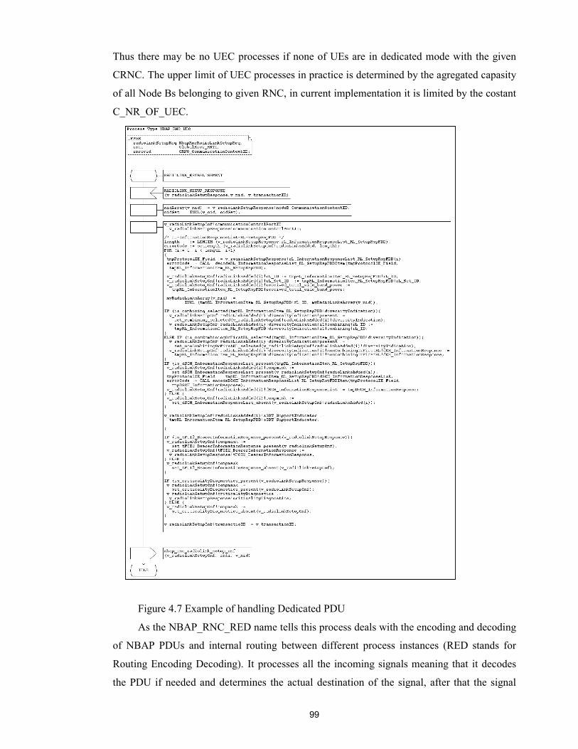
99
Thus there may be no UEC processes if none of UEs are in dedicated mode with the given
CRNC. The upper limit of UEC processes in practice is determined by the agregated capasity
of all Node Bs belonging to given RNC, in current implementation it is limited by the costant
C_NR_OF_UEC.
Figure 4.7 Example of handling Dedicated PDU
As the NBAP_RNC_RED name tells this process deals with the encoding and decoding
of NBAP PDUs and internal routing between different process instances (RED stands for
Routing Encoding Decoding). It processes all the incoming signals meaning that it decodes
the PDU if needed and determines the actual destination of the signal, after that the signal
100
with ready-to-use parameters is routed to destination process. For routing the RED process
stores the routing tables that are used by routing routines. All routing routines are organised in
one package NBAP_Procedures and in fact can be used by both RNC and Node B RED
processes. The routing table for NBAP_RNC_COMMON processes was described above. For
NBAP_RNC_UEC processes the routing table is a bit more complicated since the UE is
addressed in different ways in downlink and uplink directions. In downlink direction the UE
is addressed by the Radio Network Temporary Identity (RNTI) and in uplink direction by the
RNC Communication Context Identifier (RNCCCID). Considering that, the routing table is
represented by the list container of elements, which in turn are the structure of RNTI,
RNCCCID and PID of UEC process. The routing tables are initialized and updated each time
when the new process is instantiated.
Above all the NBAP_RNC_RED supports the interfaces toward the ALCAP protocol.
the description of this interfece was given in the previous chapter. It's only worth to note here
that the NBAP_RNC_RED is responsible for allocation of RefID variable used to address any
particular AAL2 connection. This reference together with BindingID and Transoport Layer
Address is provided to the ALCAP in the ALCAP ESTABLISH.request
(aal2sig_establish_req in our example). Since the RNC receives from Node B only Binding
ID for transport bearer to be allocated NBAP_RNC_RED process also stores then association
table between the BindingID and generated reference. The EFSM implementing such
functionality is shown in the figure 4.8.
In this example the nbap_rnc_i_alcap_setup is received by the NBAP_RNC_RED from
the NBAP_RNC_UEC process. The UEC process forms this signal based on the parameters
received in the NBAP RADIO LINK SETUP RESPONSE PDU. It contains the BindingIDs and
Transport Layer Address for the data transport bearer to be allocated over the Iub interface.
For more information about this procedure, please refer to section 3.5.2 (in particular figure
3.26 and following discussion).
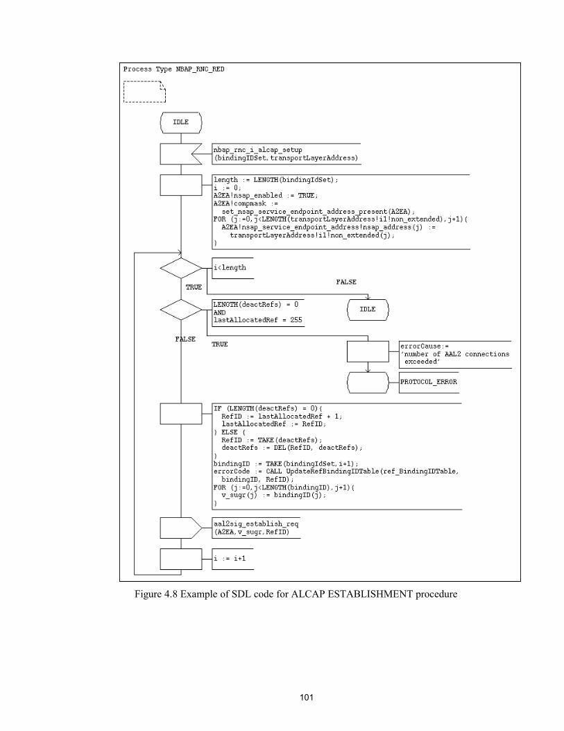
101
Figure 4.8 Example of SDL code for ALCAP ESTABLISHMENT procedure
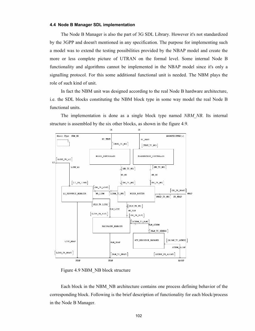
102
4.4 Node B Manager SDL implementation
The Node B Manager is also the part of 3G SDL Library. However it's not standardized
by the 3GPP and doesn't mentioned in any specification. The purpose for implementing such
a model was to extend the testing possibilities provided by the NBAP model and create the
more or less complete picture of UTRAN on the formal level. Some internal Node B
functionality and algorithms cannot be implemented in the NBAP model since it's only a
signalling protocol. For this some additional functional unit is needed. The NBM plays the
role of such kind of unit.
In fact the NBM unit was designed according to the real Node B hardware architecture,
i.e. the SDL blocks constituting the NBM block type in some way model the real Node B
functional units.
The implementation is done as a single block type named NBM_NB. Its internal
structure is assembled by the six other blocks, as shown in the figure 4.9.
Figure 4.9 NBM_NB block structure
Each block in the NBM_NB architecture contains one process defining behavior of the
corresponding block. Following is the brief description of functionality for each block/process
in the Node B Manager.

103
�� NODEB_ROUTER has only the responsibility to route all receiving signals to the
corresponding destination processes. From this point it act pretty similar as
NBAP_RNC_RED process described above, except that it doesn't perform routing. All
signals in the downlink direction traverse through the NODEB_ROUTER.
�� NODEB_CONTROLLER performs all functionality required for the Logical O&M
of Node B. All NBAP primitives related to the Logical O&M are terminated there. Some of
the NBAP O&M actions initiated by Node B are trigged in NODEB_CONTROLLER through
OM interface.
�� MEASUREMENT_CONTROLLER takes care about all measurement related
activities. The NBAP COMMON and DEDICATED MEASUREMENT procedures are
terminated and treated there.
�� RADIOLINK_MANAGER contains the main process that is responsible for setting
up first Radio Link for the UE. It has the interface towards the NBAP protocol entity through
which it provides its services. The main service provided to NBAP is allocation of Node B
Communication Context Id for newly created UE connection. Besides this it partially
performs transport resource management tasks. They are concluded in managing Traffic
Termination Points. When the Node B Communication Context is created (upon the setup of
first Radio Link) the RADIOLINK_MANAGER chooses the Traffic Termination Point to be
assigned to that Node B Communication Context, i.e. the point at which all dedicated UE
traffic is terminated and mapped to the transport bearer. For that RADIOLINK_MANAGER
has the set of Traffic Termination Point Identifiers (TTPIDs) available for the given Node B.
The choice for the particular TTPID is done based on the on-load algorithm, i.e. the particular
UE connection being setup is assigned to that Traffic Termination Point which has the least
load (serving the least number of Radio Links). The RADIOLINK_MANAGER continuously
controls the load of each Traffic Termination Point. For that it stores the table containing the
TTPIDs and number of Radio Links associated with them. Each time when the new Radio
Links are added to the existing Node B Communication Context the
L1_RESOURCE_MANAGER reports their number to the RADIOLINK_MANAGER, which
makes the update of the load table. The choosing algorithm as well as all activities related to
the support of load table are implemented in the form of procedures and included in the SDL
package NBM_Procedures. The example of SDL code from the RADIOLINK_MANAGER
block is shown in the figure 4.10.
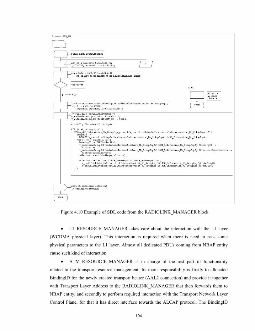
104
Figure 4.10 Example of SDL code from the RADIOLINK_MANAGER block
�� L1_RESOURCE_MANAGER takes care about the interaction with the L1 layer
(WCDMA physical layer). This interaction is required when there is need to pass some
physical parameters to the L1 layer. Almost all dedicated PDUs coming from NBAP entity
cause such kind of interaction.
�� ATM_RESOURCE_MANAGER is in charge of the rest part of functionality
related to the transport resource management. Its main responsibility is firstly to allocated
BindingID for the newly created transport bearer (AAL2 connection) and provide it together
with Transport Layer Address to the RADIOLINK_MANAGER that then forwards them to
NBAP entity, and secondly to perform required interaction with the Transport Network Layer
Control Plane, for that it has direct interface towards the ALCAP protocol. The BindingID

105
that is allocated here has the length of four octets. In fact the
ATM_RESOURCE_MANAGER allocated only the half of this length, i.e. two octets, the rest
two octets are initialized at the RNC side (actually by the NBAP_RNC_UEC process) by the
NodeB ID (NID) value. This is required in order to avoid interleaving of Binding Ids
allocated in different Node Bs that belong to the same RNC. Besides this the
ATM_RESOURCE_MANAGER creates and stores the association between the reference
generated by the NBAP_RNC_RED process (RefID), and provided by the ALCAP in
ESTABLISH.indication primitive, and BindingID.
4.5 Experience
As it was described in the first chapter the specification of 3G systems is divided into
release phases. The release separation was done in order to provide smooth and seamless way
of evolution from second-generation to third-generation systems. But from the other hand this
implies the continuous nature of changes in specifications. Within each release phase the
specifications are changed upto dozen of times. At the moment the specifications for some
protocols, such as MAC or RRC are stable enough, but for another are not. The application
protocols, and NBAP in particular, are the ones of those that still have a lot of changes from
one release version to another. The new version update is released basically once in three –
four months, sometimes the ASN.1 definitions are changed or even new procedures are
added. All this requires continuous update of the protocol models.
Fortunately the ASN.1 definitions coming from the specifications are quite well unified,
that allows to use sometimes uniform methods for adaptation of the definitions and generating
encoding/decoding functions, for example. This made possible to create commonly used Perl
scripts for generating needed functions and "user friendly" definitions for PDUs.
The concept of "user friendly" PDUs has emerged due to the complexity of ASN.1
definitions coming from the specifications and inability to use them in SDL code. The idea
was to create more simple definitions for PDUs keeping their structure intact. That also
required extension of encoding/decoding functions to transform decoded PDUs to the "user
friendly" format. Although it is good as a temporary solution, it is not an answer for the long-
term employment. Instead the support of these advanced ASN.1 features from ASN.1 tools is
expected in the future.
Another problem caused by the complexity of ASN.1 definitions was such that
sometimes ASN.1 tools were not ready to process such kind of huge and complex ASN.1
structures. As a result system crashed during the simulation. Although the SDT Simulator
supports tracing facilitities, they are not enough to find such kind of bugs. Often the

106
debugging on the C level had to be used, which is, considering the amount of C code
generated by SDT, extremely difficult task. But step by step as the bugs in tools were reported
they have been taken into account and now the ASN.1 tools are more or less stable.
But still one significant problem with ASN.1 tools remains. At the time the
implementation was done there was no support for dynamic memory allocation for the types
generated from ASN.1 definitions, or that support was not stable enough to be employed
throughout the whole library. As a result the ASN.1 type constructors such as SEQUENCE
OF and SET OF were translated into static arrays. This has led to the enormous memory
consumption. Some temporary solutions have been employed to decrease memory
consumption, such as forced limitation of the generated arrays. But it is not a solution for the
long-term perspective. Instead the support for dynamic memory from ASN.1 tools is expected
to use in the future. In addition there are some ideas how to optimize the ASN.1 structure for
primitives and make some changes in SDL code that could also minimize the memory
consumption.
In the rest ASN.1 Nokia tools and Telelogic SDT are quite powerful tools and fairly
easy to use. The graphical user interface of the SDT as well as SDL graphical notation are
quite simple and fast to learn. Besides the implementation the SDT gives a lot of assistant
during the testing phase. The MSC and SDL trace functionality of SDT is very handy to use
for debugging on the SDL level. Although the SDT takes care about the low-level
implementation issues, a lot of responsibility is still left to the programmer, that gives him
enough freedom and flexibility in the implementation decisions.
107
5. CONCLUSION
Selection of transport architecture for the 3G cellular network is not an easy task.
Explosive growth in cellular users, new services including Internet and multimedia, backward
compartibility and convergence of wireless and wireline networks are some of the key issues
that will play a major role in selecting a transport architecture. The aim of this paper was to
indicate the different options possible for future cellular networks (that was done in the first
section), and then to examine the current choice of transport technology within the UTRAN
on the example of Iub interface (presented in the rest of the paper). The work was
concentrated on the overview of transport resource management tasks performed by different
protocols at the Iub interface and in particular by the NBAP application protocol that was in
question of practical implementation.
As the study has indicated, to meet the stringent requirements of cellular telephony the
standardization process consider the ATM to be the essential transport technology at the
current stage of 3G evolution (3GPP Rel99). And at least in part of UTRAN the ATM
dominates also in the next phase, defined in 3GPP Release 4.
The ATM offers an integrated solution to voice (circuit mode as well as packet voice),
data and video. QoS guarantee, reliability and a service model that is similar to telecom
networks are other reasons why ATM is a preferred option as a transport technology. To meet
a specific requirements of mobile telephony the ATM is used together with its adaptation
layers, namely with AAL2 and AAL5.
At the same time the dominance of IP protocols in data networks and recent efforts in
incorporating QoS provisioning mechanisms in IP have given impetus to a number of studies
on experimenting with IP as a transport technology in 3G cellular networks. As mentioned
earlier mobile telephony has been the dominant application in the wireless networks, and
requires that the underlying transport technology is capable of supporting QoS guarantee. One
of the hurdles for IP has been its inability to solve the QoS issues.
The standrdization of the transport protocols for the UMTS Release 99 has already been
completed in 3GPP. When the work was started several years ago, ATM was thought to be
the default transport technology in 3G. However during the last few years there has been a
change in this view: the role of IP gained more and more importance during the
standardization process. The efforts towards integrating QoS provisioning mechanisms such
as differentiated services (Diff-serv) and integrating services have given a new hope of using
IP in 3G cellular infrastructure. Not the least, IP terminal adaptability, the same terminals
being used in both wireless and wireline networks, is also an important factor which favours
the use of IP.
108
From this point the Voice over IP solutions are considered as a key for a successful IP
based cellular infrastructure. For data and video, it has been proven that IP is the optimal
technology.
All this efforts has led to the so called All-IP based architecture defined in the 3GPP
Release 5 (see figure 1.3).
Although the transport resource management objectives and functionality changes
significantly together with changing of transport technology itself, the view on the transport
resources and thus the means to manage them from the Radio Network Layer point of view
remains intact. That was the main idea in order to provide seamless protocol evolution along
with the evolution of transport in UTRAN from ATM to IP. The application protocols have
been successfully isolated from the transport layers, which makes the protocol evolution easy.
On the example of NBAP implementation this work has shown that it's independent from the
underlying transport technology in terms of both signalling transport and management of
transport resources (in part of NBAP responsibility); the latter is ensured by the introduction
of the Transport Network Control Plane at the Iub interface, physically implemented by the
ALCAP protocol.
In that way this work has shown that the transport resource management tasks can be
divided into different abstraction levels seen from the Radio Network Layer and Transport
Network Layer. The direct transport technology dependent activity is performed from the
Transport Network Layer by the ALCAP protocol, which itself obeys the commands from the
Radio Network Layer. In current realization of 3G SDL Library the NBAP and NBM are the
ones that provide such kind of interaction with ALCAP. To such an extent the NBAP and the
NBM contribute to the transport resource management at the Iub interface.
However the interface between the NBAP and ALCAP, and all the more Node B
Manager, is not standardized by the 3GPP; all these are left as implementation specific issues.
Nevertheless their design and implementation should be done very carefully, because the
efficiency of transport resource management functions at the Iub interface have the crusial
impact on the successful operation of the overall UMTS network.
109
REFERENCES
[1]. H.Kaaranen, A. Ahtiainen, L. Laitinen, S. Naghian, V. Niemi, UMTS Networks,
John Wiley & Sons, 2001.
[2]. NOKIA 3G Training, UMTS Radio Path and Transmission, Nokia Networks Oy.
[3]. Technical Specification 25.211 version 4.2.0: Physical Channels and mapping of
transport channels onto physical channels (FDD), 3GPP, 2001.
[4]. Technical Specification 25.401 version 4.1.0: UTRAN Overall Description, 3GPP,
2001.
[5]. ITU-T Recommendation Q.2630.1 "AAL2 Signalling Protocol" (07/94).
[6]. Technical Specification 25.430 version 4.0.0: UTRAN Iub Interface: General
Aspects and Principles, 3GPP, 2001.
[7]. Technical Specification 25.426 version 4.4.0: UTRAN Iur & Iub Interface Data
Transport & Transport Signalling for DCH Data Streams, 3GPP, 2001.
[8]. B-ISDN ATM Adaptation Layer, ITU-T Recommendation Q.2100, 1994
[9]. Technical Specification 25.434 version 4.2.0: UTRAN Iub Interface Data
Transport and Transport Signalling for Common Transport Channel Data
Streams, 3GPP, 2001.
[10]. Technical Report 25.990 version 4.0.0: Vocabulary, 3GPP, 2001.
[11]. Technical Specification 25.427 version 4.2.0: UTRAN Iub/Iur Interface User
Plane Protocol for DCH Data Streams, 3GPP, 2001.
[12]. Technical Specification 25.435 version 4.4.0: UTRAN Iub Interface User Plane
Protocols for Common Transport Channel Data Streams, 3GPP, 2001.
[13]. Technical Specification 25.402 version 4.2.0: Synchronisation in UTRAN Stage 2,
3GPP, 2001.
[14]. M. Ford, H. Kim, S. Spanier, T. Stevenson: Interworking Technology Overview
2nd edition, June 1999.
[15]. ITU-T Recommendation Q.2630.2 "AAL2 Signalling Protocol (Capability Set
2)".
[16]. Technical Specification 25.433 version 4.1.0: UTRAN Iub Interface: NBAP
Signalling, 3GPP, 2001.
[17]. Technical Specification 25.432 version 4.1.0: UTRAN Iub Interface: Signalling
Transport, 3GPP, 2001.
110
[18]. Recommendation ITU-T X.691: Information technology – ASN.1 encoding rules –
Specification of Packed Encoding Rules (PER), ITU, 1997.
[19]. Pressman Roger s., Software Engineering. A practitioner's Approach, Forth
Edition, The McGraw-Hill Companies, USA, 1997.
[20]. Recommendation ITU-T X.680: Information technology – Abstract Syntax
Notation One (ASN.1): Specification of basic notation, ITU, 1997
[21]. Technical Specification 23.110 version 3.1.0: UMTS Access Stratum; Services
and Functions, 3GPP, 1999.
[22]. Technical Specification 25.331 version 3.3.0: RRC Protocol Specification, 3GPP,
2000.
[23]. Technical Specification 25.413 version 3.1.0: UTRAN Iu Interface RANAP
Signalling, 3GPP, 2000.
[24]. Technical Specification 25.433 version 3.3.0: UTRAN Iur Interface RNSAP
Signalling, 3GPP, 2000.
[25]. Technical Report 25.931 version 3.0.0: UTRAN Functions, Examples on
Signalling Procedures, 3GPP, 2000.
[26]. Technical Specification 25.213 version 3.2.0: Spreading and modulation (FDD),
3GPP, 2000.
[27]. Technical Specification 25.442 version 3.1.0: UTRAN Implementation Specific
O&M Transport, 3GPP, 2000.
[28]. ITU-T Recommendation q.2130. (07/94). “B-ISDN signalling ATM adaptation
layer – Service specific co-ordination function for support of signalling at the user
network interface (SSCF–UNI)”.
[29]. ITU-T Recommendation Q.2110 (07/94). “B-ISDN ATM adaptation layer –
Service specific connection oriented protocol (SSCOP)”.
[30]. Recommendation ITU-T Z.100: CCITT Specification and Description Language
(SDL), ITU, 1994.
[31]. Holma Harry, Toskala Antti: WCDMA for UMTS. Radio Access For Third
Generation Mobile Communications, John Wiley & Sons, 2000.
[32]. Mouly Michel, Pautet Marie-Bernadette: The GSM System for Mobile
communications, Published by the authors, 1992.
[33]. David E. McDysan, Darren L. Spohn. ATM Theory and Application, McGraw-
Hill Series on Computer Communications, 1998.
111
[34]. Ellsberger Jan, Hogrefe Dieter, Sarma Amardeo: SDL – Formal Object-oriented
Language for Communicating Systems, Prentice Hall, London, 1997.
[35]. 3G System. Training material, Nokia Networks Oy, Finland, 2000.
[36]. Understanding Telecommunications 1, Ericsson Telecom AB, Telia AB and
Studentlitteratur, Sweden, 1997.
[37]. Gert-Jan Van Lieshout, Iur, Iub interface, Materials of advanced technical
seminar. UTRAN Signaling. 18-19 September 2000, Stockholm, Sweden.
[38]. Telelogic AB: SDT 3.5 Reference Manual, 2000
[39]. Holzmann, Design and Validation of computer protocols, Prentice-Hall, 1991
[40]. Tervonen Janne, Radio Access Bearer Management Protocol in 3rd Generation
Mobile Telecommunications System, Master's Thesis, Helsinki University of
Technology, 2000.
[41]. Issaeva Tatiana, Radio Subsystem Management in 3G Mobile Communications,
Master's Thesis, Lappeenranta University of Technology, 2000.
[42]. www.telelogic.com
[43]. www.3gpp.org
[44]. ISO 8824(90)/X.208(88) Information technology - Open Systems Interconnection
- Specification of Abstract Syntax Notation One (ASN.1).
[45]. Juhä Sipilä, Vesa Luukkala, An SDL Implementation Framework for Third
Generation Mobile Communication System, Nokia Research Center, Mobile
Network Laboratory, 2001.