TRANSNET SOC LTD DCT BERTHS 203 TO 205 - · PDF filetransnet soc ltd dct berths 203 to 205...
49
TRANSNET SOC LTD DCT BERTHS 203 TO 205 ‐ RECONSTRUCTION, DEEPENING AND LENGTHENING PORT OF DURBAN SPECIFICATION – CORROSION PROTECTION 1370‐CO‐000‐C‐SPC‐0017 Rev T‐0B 21 APRIL 2017
Transcript of TRANSNET SOC LTD DCT BERTHS 203 TO 205 - · PDF filetransnet soc ltd dct berths 203 to 205...
TRANSNET SOC LTD
DCT BERTHS 203 TO 205 ‐ RECONSTRUCTION, DEEPENING AND
LENGTHENING
PORT OF DURBAN
SPECIFICATION – CORROSION PROTECTION
1370‐CO‐000‐C‐SPC‐0017 Rev T‐0B
21 APRIL 2017
TRANSNET SOC LTD DCT BERTHS 203 TO 205 – RECONSTRUCTION, DEEPENING AND LENGTHENING
PORT OF DURBAN
SPECIFICATION – CORROSION PROTECTION
1370‐CO‐000‐C‐SPC‐0017 Rev T‐0B April 2017
REVISIONS
REV DATE DESCRIPTION DESIGNED
BY
CHECKED
BY
APPROVED
BY
T‐00 31 May 2016 Issue for Review NW MC JZ
T‐0A 18 November 2016 Issue for Tender NW MC JZ
T‐0B 21 April 2017 Annexure 3 added NW MC JZ
AUTHORISATION
AUTHORISED BY NAME SIGNATURE DATE
DIRECTOR J ZIETSMAN Pr Eng
21 April 2017
This document, including all design and information therein, is Confidential Intellectual Property of
ZAA Engineering Projects and Naval Architecture (Pty) Ltd.
Copyright and all other rights are reserved by ZAA Engineering.
This document may only be used for its intended purpose.
TRANSNET SOC LTD DCT BERTHS 203 TO 205 – RECONSTRUCTION, DEEPENING AND LENGTHENING
PORT OF DURBAN
SPECIFICATION – CORROSION PROTECTION
1370‐CO‐000‐C‐SPC‐0017 Rev T‐0B April 2017
CONTENTS
1.0 SCOPE .................................................................................................................................................... 1
1.1 Project ..................................................................................................................................................... 1 1.2 Scope ....................................................................................................................................................... 1
2.0 NORMATIVE REFERENCES ........................................................................................................................ 1
2.1 Reference Documents ............................................................................................................................. 1 2.2 Standard Specifications ........................................................................................................................... 1 2.3 Employer’s Project Specific Specifications and Standards ........................................................................ 1
3.0 DEFINITIONS ............................................................................................................................................ 2
3.1 Chart Datum Port ..................................................................................................................................... 2 3.2 Co‐ordinate System ................................................................................................................................. 2 3.3 Tidal Levels .............................................................................................................................................. 2 3.4 Method Statements ................................................................................................................................ 2
4.0 REQUIREMENTS ....................................................................................................................................... 3
4.1 Method Statement .................................................................................................................................. 3 4.2 Equipment ............................................................................................................................................... 3 4.3 Methods and Procedures ......................................................................................................................... 3
4.3.1 Coatings ......................................................................................................................................... 3
4.3.1.1 Extent of work ............................................................................................................................... 3 4.3.1.2 Coating and supply and application methodology ........................................................................ 3 4.3.1.3 Anodes fabrication, supply and application methodology ............................................................ 4 4.3.1.4 Repair of damaged coatings .......................................................................................................... 4 4.3.1.5 Quality Assurance Requirements and Quality Control .................................................................. 4
ANNEXURE 1: ISINYITHI CATHODIC PROTECTION SPECIFICATIONS: PORT OF DURBAN BERTHS 203 TO 205 RETURN
WALL STEEL PILES 5690/130999 EXTERNAL COATING SPECIFICATION ....................................................................... 1 ANNEXURE 2: ISINYITHI CATHODIC PROTECTION SPECIFICATIONS: PORT OF DURBAN BERTHS 203 TO 205 RETURN
WALL STEEL PILES 5690/130999 GALVANIC ANODES SPECIFICATION ........................................................................ 2 ANNEXURE 3: DESIGN REPORT ZAA 1370‐RPT‐063.................................................................................................... 3
TRANSNET SOC LTD DCT BERTHS 203 TO 205 – RECONSTRUCTION, DEEPENING AND LENGTHENING
PORT OF DURBAN
SPECIFICATION – CORROSION PROTECTION
1370‐CO‐000‐C‐SPC‐0017 Rev T‐0B April 2017
Page | 1
1.0 SCOPE
1.1 Project
This specification is a project specific technical specification for the DCT Berths 203 to 205 Reconstruction, Deepening
and Lengthening Project in the Port of Durban.
1.2 Scope
The scope of this specification covers the Employer’s requirements for the provision of corrosion protection in the
form of Epoxy glass flake coatings and sacrificial aluminium anodes for the Berth 205 circular straight steel sheet pile
return quay.
The specification details the requirements of Materials, Equipment and Procedures to be adopted by the Contractor
to supply, apply and install the corrosion protection for the return quay.
2.0 NORMATIVE REFERENCES
2.1 Reference Documents
The following Employer and industry standardized specifications are referenced in this specification and form part of
the Works Information. Standard specifications referenced within the specifications listed below also form part of
the Works Information.
Reference documents to be used by the Contractor shall include:
a) This Specification.
b) Industry Codes, Standards and Specifications as listed in Section 2.2.
c) Project Drawings:
─ 1370‐CO‐070 series of drawings – Return Quay
─ 1370‐CO‐020 series of drawings – Dredging and Reclamation (anodes installed after completion of
local basin dredging).
d) Employer’s Project Specific Technical Specifications as listed in Section 2.2.
e) Method Statements prepared by the Contractor, as described in Section 4.1.
2.2 Standard Specifications
The standard specifications listed in this section shall, inter alia, be read in conjunction with the following
specifications
a) Recommended Practice DNV‐RP‐F103 – Cathodic Protection of Submarine Pipelines by Galvanic Anodes,
2010
b) Recommended Practice DNV‐RP‐F106 – Factory Applied External Pipeline Coatings for Corrosion Control,
2011
c) SANS ISO 15589‐2: 2009, Edition 1 (ISO 15589‐2:2004, Edition 1) – Petroleum and Natural Gas Industries –
Cathodic Protection of Pipeline Transportation Systems – Part 2: Offshore Pipelines
d) SANS 53509:2009, Edition 1 (EN 13509:2003, Edition 1) – Cathodic Protection Measurement Techniques
e) Isinyithi Cathodic Protection ‐ 5690/130999 Port of Durban Berths 203 to 205 Return Wall Steel Piles
External Coating Specification
f) Isinyithi Cathodic Protection – 5890/130999 Port of Durban Berths 203 to 205 Return Wall Steel Piles
Galvanic Anode Specification
2.3 Employer’s Project Specific Specifications and Standards
The specifications listed in this section shall, inter alia, be read in conjunction with this specification.
a) 1370‐CO‐000‐C‐SPC‐0009 – Steel Sheet Piling.
b) Environmental Management Plan (EMP).
TRANSNET SOC LTD DCT BERTHS 203 TO 205 – RECONSTRUCTION, DEEPENING AND LENGTHENING
PORT OF DURBAN
SPECIFICATION – CORROSION PROTECTION
1370‐CO‐000‐C‐SPC‐0017 Rev T‐0B April 2017
Page | 2
3.0 DEFINITIONS
All definitions of responsibilities shall be in accordance with the NEC Engineering and Construction Contract (ECC) for
the construction of the Works.
Where the standard specifications referenced in this specification refer to the “Client”, replace this term with the
term “Employer”.
Where the standard specifications referenced in this specification refer to the “Engineer”, replace this term with the
term “Supervisor”.
For the purpose of this specification, the technical definitions and abbreviations given in SANS 15589-2:2009/ISO
15589-2:2004, (approved 2009) together with the following definitions shall apply:
3.1 Chart Datum Port
Chart Datum Port refers to the reference level used in the Port of Durban, which is 0,900 m below Mean Sea Level.
All levels referred to in this document are relative to Chart Datum Port (CDP).
3.2 Co‐ordinate System
The co‐ordinate system to be used for all setting out and survey shall be World Geodetic System 1984 (WGS84),
LO31, referred to as WG31.
3.3 Tidal Levels
The Astronomical Tide Predictions as defined by the SA Navy Hydrographer and Chart SAN 2006 are as follows:
Table 3.1 – Tide Data
Tide Abbreviation Level m, Chart Datum Port
Highest Astronomical Tide HAT 2.287
Mean High Water Springs MHWS 1.997
Mean Level ML 1.097
Mean Low Water Springs MLWS 0.197
Lowest Astronomical Tide LAT ‐0.013
3.4 Method Statements
Method statements shall be compiled by the Contractor for all activities. The method statements shall be submitted
to the Supervisor for acceptance three weeks in advance of the particular activity being undertaken. Full details of all
proposed Equipment (including temporary works) and methods shall be provided for acceptance by the Supervisor.
No activity shall commence until the method statement has been accepted by the Supervisor.
Further details of the requirements of particular method statements are provided in Section 4.
TRANSNET SOC LTD DCT BERTHS 203 TO 205 – RECONSTRUCTION, DEEPENING AND LENGTHENING
PORT OF DURBAN
SPECIFICATION – CORROSION PROTECTION
1370‐CO‐000‐C‐SPC‐0017 Rev T‐0B April 2017
Page | 3
4.0 REQUIREMENTS
4.1 Method Statement
The Contractor shall prepare method statements that shall include, inter alia:
a) Supply and application of corrosion protection in the form of Zip‐E Epoxy glass flake coatings for the Berth
205 circular straight steel sheet pile return quay.
b) Fabrication, Supply, installation and commissioning of corrosion protection in the form of sacrificial
aluminum anodes for the Berth 205 circular straight steel sheet pile return quay.
c) Quality Plans.
4.2 Equipment
The Contractor shall take full and entire responsibility for the sufficiency of his Equipment to Provide the Works. The
Contractor shall submit details of all Equipment to be used to the Supervisor for acceptance at least 3 weeks prior to
dredging and reclamation work commencing.
4.3 Methods and Procedures
4.3.1 Coatings
4.3.1.1 Extent of work
a) The extent of work, corrosion protection and levels are as shown on the 1370‐CO‐070 series of drawings.
The following corrosion protection measures shall be undertaken in accordance with the specifications:
─ Isinyithi Cathodic Protection specifications: Port of Durban Berths 203 to 205 Return Wall Steel Piles
5690/130999 External Coating Specification and
─ Isinyithi Cathodic Protection specifications: Port of Durban Berths 203 to 205 Return Wall Steel Piles
5890/130999 Galvanic Anodes Specification
b) Where the Contractor proposes using alternative proprietary coating systems to those specified in
Annexure 1, the coating system proposed shall be designed in accordance with the design report provided
in Annexure 3.
c) The piles will be fully coated on the sea face to reduce CP current requirements and enable the 50‐year
design life without anode replacement.
d) The top section of all piles shall be coated on both faces to 1m below the level of the capping beam to
provide supplementary protection in the intertidal zone and prevent localised corrosion of the steel
adjacent to the encasement of the capping beam.
e) The anodes shall only be installed after dredging of the basin (1370‐CO‐020 series of drawings) using bolted
mounting brackets with the welded connections above the water line.
f) All electrical connections between anodes and the pile SHALL be welded. NO bolted connections to the pile
may be employed.
4.3.1.2 Coating and supply and application methodology
Coatings supply and application methodology shall be in accordance with the requirements of Isinyithi Cathodic
Protection specification: Port of Durban Berths 203 to 205 Return Wall Steel Piles 5690/130999 External Coating
Specification.
Where this specification states in Section 3.10 Material Supplier: “No alternative products or Suppliers will be
considered”, replace this with “use of alternative products or Suppliers will be subject to the approval of the
Supplier”.
TRANSNET SOC LTD DCT BERTHS 203 TO 205 – RECONSTRUCTION, DEEPENING AND LENGTHENING
PORT OF DURBAN
SPECIFICATION – CORROSION PROTECTION
1370‐CO‐000‐C‐SPC‐0017 Rev T‐0B April 2017
Page | 4
4.3.1.3 Anodes fabrication, supply and application methodology
Anodes fabrication, supply and application methodology shall be in accordance with the requirements of Isinyithi
Cathodic Protection specification: Port of Durban Berths 203 to 205 Return Wall Steel Piles 5890/130999 Galvanic
Anodes Specification
4.3.1.4 Repair of damaged coatings
Repair of damaged coatings during transportation and installation shall be in accordance with the requirements of
Isinyithi Cathodic Protection specification: Port of Durban Berths 203 to 205 Return Wall Steel Piles 5690/130999
External Coating Specification.
4.3.1.5 Quality Assurance Requirements and Quality Control
Quality Assurance and Control shall be undertaken in accordance with the specifications:
a) Isinyithi Cathodic Protection specifications: Port of Durban Berths 203 to 205 Return Wall Steel Piles
5690/130999 External Coating Specification; and
b) Isinyithi Cathodic Protection specifications: Port of Durban Berths 203 to 205 Return Wall Steel Piles
5890/130999 Galvanic Anodes Specification.
TRANSNET SOC LTD DCT BERTHS 203 TO 205 – RECONSTRUCTION, DEEPENING AND LENGTHENING
PORT OF DURBAN
SPECIFICATION – CORROSION PROTECTION
1370‐CO‐000‐C‐SPC‐0017 Rev T‐0B Annexures April 2017
Page | A1
ANNEXURE 1: ISINYITHI CATHODIC PROTECTION SPECIFICATIONS: PORT OF
DURBAN BERTHS 203 TO 205 RETURN WALL STEEL PILES 5690/130999 EXTERNAL
COATING SPECIFICATION
C O N F I D E N T I A L R E P O R T
CLIENT : ZAA Engineering Projects & Naval Architecture
PROJECT : Port of Durban Berths 203 - 205 Return Wall Steel Piles
SCOPE : EXTERNAL COATING SPECIFICATION
DATE : October 2015
REF : 5690/130999 Draft for comment
Responsibility rests with the reader to verify that this is the latest revision
Report by: _____________________
N C Webb
Internal Review: _____________________
V Sealy-Fisher
Isinyithi Cathodic Protection (Pty) Ltd Page 2 of 20 5690130999 Confidential Report
Reports are submitted to clients on a confidential basis;
No reference to the work or test results in any manner will be discussed or made public without
written authorisation from the client;
All work is considered proprietary property of the client and is maintained by ICP as such.
Disclaimer: Responsibility rests with the reader to verify the latest revision of the report.
Isinyithi Cathodic Protection (Pty) Ltd Page 3 of 20 5690130999 Confidential Report
DOCUMENT CONTROL
Job Title Port of Cape Town Berth 203-205
Document title Wall Pile Coating Specification
Project Number 130999
Document Reference 5690
Revision Date Revision Description Issued for comment
0 28/10/2015 Prepared By Checked by
Name N C Webb V Sealy-Fisher
Signature
Revision Date Revision Description
Prepared By Checked by
Name
Signature
Revision Date Revision Description
Prepared By Checked by
Name
Signature
Isinyithi Cathodic Protection (Pty) Ltd Page 4 of 20 5690130999 Confidential Report
TABLE OF CONTENTS
1 INTRODUCTION ........................................................................................................................ 5
2 SURFACE PREPARATION & COATING APPLICATION .......................................................... 9
3 QUALITY ASSURANCE REQUIREMENTS ............................................................................. 13
4 REFERENCE DOCUMENTS AND STANDARDS .................................................................... 16
5 SURFACE PREPARATION & EXTERNAL COATING APPLICATION OF SITE REPAIRS ..... 17
6 EXTERNAL COATING SYSTEM SUMMARY .......................................................................... 20
7 SITE REPAIR COATING SYSTEM SUMMARY ....................................................................... 20
Port of Cape Town Berth 203-205 Return Wall Pile Coating Specification
Isinyithi Cathodic Protection (Pty) Ltd Page 5 of 20 5690130999 Confidential Report
1 INTRODUCTION
1.1 Application of Specification
Unless otherwise agreed by the Engineer in writing, the materials and specifications used shall
follow strictly the clauses of this specification.
1.2 Supervision of Work
All work shall be carried out under the constant supervision of a qualified supervisor. At least one
supervisor shall be present at all times and at no period will unsupervised work be permitted.
1.3 Materials Delivered to Site or Shop
All coatings in the system shall be sourced from the specified supplier unless otherwise agreed
and be brought to site in new unopened containers. Containers shall be clearly marked with the
relevant material type, code and production batch numbers.
1.4 Approval of Manufacturer
Only approved materials may be utilised for the corrosion protection work. Therefore, the
successful Tenderer shall obtain the Engineer's prior approval of materials and manufacturer, prior
to the commencement of work.
1.5 Coating Defects
All coating application shall be free of runs and other paint film defects. All painted surfaces shall
be free from dust, dirt, blasting media, sand and salt contamination.
1.6 Cleaning
In the case of site coating, the surface shall be prepared as indicated in this specification.
No blast cleaning or coating application shall take place during inclement weather or when
conditions are such as to cause contamination of coatings. It is the Contractor's responsibility to
provide screens, covers, trestles or any other equipment necessary to minimise stoppage time
through the conditions mentioned.
No early morning or late evening coating shall take place when steel surfaces are wet owing to
overnight and early evening dew formation.
Port of Cape Town Berth 203-205 Return Wall Pile Coating Specification
Isinyithi Cathodic Protection (Pty) Ltd Page 6 of 20 5690130999 Confidential Report
1.7 Contamination During Coating Application
The Contractor shall take adequate precautions to protect areas being coated against
contamination and fall out during painting operations, should this become necessary.
All staff involved with coating to be issued with clean disposable over shoes and over cloth
disposable overalls. A clean work area shall be maintained around the piles.
1.8 Oil or Grease Surface Contamination
No coating shall be applied to any surface contaminated by oil, grease or salt deposits. Any
contaminated surfaces are to be cleaned down by means of one or more of:
a. Potable water and bristle brush,
b. A suitable water emulsifiable degreaser,
c. High pressure water washing,
d. Hot water washing
Followed by blast-cleaning
1.9 Time Limit to Coating Blast Cleaned Surfaces
After blast cleaning, operators handling the steel shall wear oil free and lint free gloves. Handling
equipment that contacts the surface shall be dry and free from oil and grease.
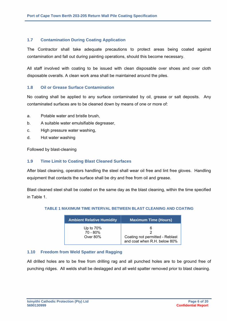
Blast cleaned steel shall be coated on the same day as the blast cleaning, within the time specified
in Table 1.
TABLE 1 MAXIMUM TIME INTERVAL BETWEEN BLAST CLEANING AND COATING
Ambient Relative Humidity Maximum Time (Hours)
Up to 70% 70 - 80% Over 80%
6 2
Coating not permitted - Reblast and coat when R.H. below 80%
1.10 Freedom from Weld Spatter and Ragging
All drilled holes are to be free from drilling rag and all punched holes are to be ground free of
punching ridges. All welds shall be deslagged and all weld spatter removed prior to blast cleaning.
Port of Cape Town Berth 203-205 Return Wall Pile Coating Specification
Isinyithi Cathodic Protection (Pty) Ltd Page 7 of 20 5690130999 Confidential Report
1.11 Repairs to the Coating System Damaged During Transport, or Other Site Activities.
If in the opinion of the Engineer, the coating system is excessively damaged during transport or
other site activities, it shall be repaired by the following procedure:
1.11.1 Test the coating surface for cure using MEK in accordance with ASTM 5402.
1.11.2 If the test indicates that the surface is not fully cured (sticky), the damaged region should be
repaired as follows:
a. Abrade the damaged area with medium grade abrasive paper (220 or 150 grit) to
clean exposed steel to a white metal finish. Abrade the coating surface for not less
than 25mm on each side of the damaged area and feather smoothly into the sound
coating
b. Remove all dust and debris.
c. Wipe the area with solvent and recoat.
1.11.3 If the test indicates that the surface is fully cured (not sticky), the damaged region should be
repaired as follows:
a. Sweep blast the damaged area to clean exposed steel to a white metal finish.
Abrade the coating surface for not less than 25mm on each side of the damaged
area and feather smoothly into the sound coating
b. Remove all dust and debris.
c. Recoat
1.12 Application Method
Application shall be by brush, or spray as recommended by the manufacturer.
Port of Cape Town Berth 203-205 Return Wall Pile Coating Specification
Isinyithi Cathodic Protection (Pty) Ltd Page 8 of 20 5690130999 Confidential Report
1.13 Ambient Conditions
No steel shall be coated when the surface temperature exceeds 40C.
No coating or final blast cleaning shall take place when the ambient temperature is below 5C or
relative humidity above 80%.
No coating or final blast cleaning shall take place if the steel temperature is less than 5°C above
dew point.

Port of Cape Town Berth 203-205 Return Wall Pile Coating Specification
Isinyithi Cathodic Protection (Pty) Ltd Page 9 of 20 5690130999 Confidential Report
2 SURFACE PREPARATION & COATING APPLICATION
2.1 Abrasive Blasting
Abrasive blasting shall be carried out using equipment suitably designed for this purpose.
2.1.1 All blast cleaning shall be conducted as per the Coating Manufacturer’s Specifications,
Data Sheet SP1 “Surface Preparation” (Procedure 6/30) or PC1 “Pipe Coating” (Procedure
6/15).
2.1.2 Prior to blast cleaning commencing :
a. All welds shall be free of slag, slag inclusions and undercutting.
b. Adjacent areas shall be free of weld spatter and such splatter shall be removed by
grinding and/or chipping.
c. All oil and grease deposits shall be removed. In this regard, special attention shall
be paid to drillings, bolt holes, etc.
2.1.3 Blasting Conditions
Where possible the blasting shall be carried out in a controlled environment. Where
blasting is carried out in open conditions no blast cleaning shall take place during inclement
weather conditions.
2.1.4 Air Dryness
All air used for blasting shall be free from all oil and water. Suitable moisture traps shall be
incorporated on air lines to ensure that air is dry.
2.1.5 Blasting Media
Blast cleaning may be carried out using steel grit and a wheel abrator, or as approved by
the Engineer. Fresh grit shall be added daily to ensure that the required profile is achieved.
Irrespective of the material used for blasting, in all cases it shall be free of all foreign matter
such as clay, humus, chlorides, bitumen etc. The particle size distribution of the abrasive
shall be suitable to produce the specified profile.
Port of Cape Town Berth 203-205 Return Wall Pile Coating Specification
Isinyithi Cathodic Protection (Pty) Ltd Page 10 of 20 5690130999 Confidential Report
2.1.6 Standard of Blast Cleaning
All items of structural steelwork shall be blast cleaned in accordance with the Swedish
Code of Practice ISO 8501-1 to Grade A Sa3.
An average profile of 80μm with a minimum profile of 60μm is required.
2.1.7 After the initial pre grit blast, test for retained metallic salts, to levels below 70mg/m², or
especially in the base of pits marks, using the ISO salt mix equivalent conductivity test
method.
(Wattman Potassium Ferricyanide papers may be used for preliminary screening)
Should metallic salts be identified, a decontamination cycle shall be undertaken:
A decontamination cycle will consist of
blast,
wash
re-blast
re-test.
The decontamination cycle may have to be repeated.
a. If decontamination is required, this shall be conducted using Chlor*Rid
decontamination solution (100:1 for spray) to remove metallic salts. If metallic salts
are above 70 mg/m2, repeat the decontamination procedure. Experience has shown
that each Chlor*Rid wash will approximately halve the salt concentration.
b. If required, a second grit blast shall be performed in accordance with ISO 8501-1 SA
3, white metal, maintaining a minimum roughness profile of 60 microns.
2.1.8 The entire surface of the pile to be coated is to be blasted. The blast cleaning programme
will depend on rate of coating application, environmental conditions and use of de-
humidification equipment.
2.1.9 The spent grit must be removed quickly, and preparations should be made to apply the
coating as soon after blasting as possible.
Port of Cape Town Berth 203-205 Return Wall Pile Coating Specification
Isinyithi Cathodic Protection (Pty) Ltd Page 11 of 20 5690130999 Confidential Report
2.1.10 100% of the surface area of the pile to be coated shall be vacuumed, to remove micro dust.
Blowing down the surface of the pile with compressed air is not an acceptable method of
dust removal.
2.1.11 The surface shall be checked in accordance with SABS 769, maximum 0.3%, to verify the
level of cleanliness.
2.2 External Coating Application
2.2.1 The external coating shall be applied in accordance with the manufacturer’s specifications.
2.2.2 Verify that the relative humidity is below 80% and that the steel is at least 5ºC warmer than
the dew point temperature of the air before and during application. If required
dehumidification shall be used to maintain RH.
2.2.3 Spray operation shall be set up as per the manufacturer’s application data sheet.
2.2.4 All staff involved with coating to be issued with clean disposable over shoes and over cloth
disposable overalls, clean work area to be maintained around the pile.
2.2.5 The first coat of the coating material shall be spray applied to a DFT of 750 microns
nominal as per manufacturer’s data sheet.
2.2.6 Spray apply the second coat once the first coat has gelled sufficiently to carry the weight of
the second coat.
2.2.7 A total DFT of typical 1.5mm minimum average thickness shall be achieved for the ZipE
coating. For QC purposes the minimum thickness of any one test location (spot
measurement) in terms of SSPC PA2 is therefore 1.2mm.
2.2.8 Allow coating 24 hours to ambient cure
2.2.9 After full cure (time to be confirmed), the ZipE coating shall be tested using a 10kV high
voltage spark test, using a calibrated pulsed DC instrument, or calibrated AC instrument.
2.2.10 All holidays, pinholes and potential defects shall be marked up and repaired as per
standard procedure using flat bottomed drill and coating plug method. Applying further
material over the top of a pinhole is not permitted.
2.2.11 All repairs shall be re-spark tested at 10kV volts to ensure integrity of lining as per
manufacturer’s data sheet.
2.2.12 DFT tests shall be made using electronic non-destructive test instruments.
Port of Cape Town Berth 203-205 Return Wall Pile Coating Specification
Isinyithi Cathodic Protection (Pty) Ltd Page 12 of 20 5690130999 Confidential Report
2.3 Masking of Areas to be Left Uncoated
2.3.1 Any areas which require not to be coated shall be suitably masked prior to coating
operations.
2.3.2 Ends of piles which may be welded on site shall be free of coating for a distance of 200mm
Port of Cape Town Berth 203-205 Return Wall Pile Coating Specification
Isinyithi Cathodic Protection (Pty) Ltd Page 13 of 20 5690130999 Confidential Report
3 QUALITY ASSURANCE REQUIREMENTS
3.1 Contractor Qualification
The Engineer may, at his discretion, require a Quality Audit of the coating sub-contractor to ensure
that he has the management facilities, skilled staff, and quality control facilities to carry out quality
control during application of coatings to ensure compliance with the specification.
The contractor shall accept full responsibility for the quality of his work and of materials used,
irrespective of any quality surveillance that may be carried out by the Engineer or his
representative.
3.2 Quality Control
The Contractor shall have the necessary equipment and staff knowledgeable in test procedures to
carry out all the quality control required to ensure compliance with the specification. The contractor
will be required to produce a quality plan and a program for carrying out the work. The Contractor
shall maintain quality control records of all stages of the work, batch numbers of materials used,
environmental conditions, as required by the specification. Quality control shall be inclusive in the
Contractor’s tender price.
No coating procedures may commence until Quality Plan has been submitted and approved
by the Client, the Coating Supplier and the Engineer.
3.3 Quality Surveillance
Independent surveillance - The Engineer may employ an independent technically qualified
organisation to carry out quality surveillance of the work on his behalf
Program - The Contractor shall advise the Engineer timeously, in writing, when and where the
following processes will be carried out :
a. Completion of fettling or dressing prior to release for coating operations.
b. Blast cleaning and application of the coatings.
c. Repairs.
Failure of the Contractor to advise the Engineer of his program may result in rejection of the work.
Port of Cape Town Berth 203-205 Return Wall Pile Coating Specification
Isinyithi Cathodic Protection (Pty) Ltd Page 14 of 20 5690130999 Confidential Report
3.4 Access For Surveillance
For the purpose of carrying out quality surveillance, the Engineer or his representative shall be
granted access to any part of the Contractor's premises relevant to the work being carried out, at
any reasonable time. The Contractor shall provide, at his own cost, any equipment or labour
necessary to gain access to surfaces which are coated, to be coated or are in the process of being
coated
3.5 Samples
The Engineer or his representative may remove or call for any reasonable samples of materials to
be used in the coating application for quality checks. Rejection of the sample will place a hold on
the use of materials of the same batch number and may lead to rejection of all that batch of
material and the reworking of any components that have already been coated with rejected
material.
Sample plates, 300mm x 300mm, shall be blast cleaned and coated alongside the pile lengths
being coated. Sample plates shall be identified and coating operation witnessed by the
independent inspector. Two (2) sample plates shall be prepared for each shift of coating work or if
a different batch number is used in a single shift.
3.6 Destructive Testing
The Engineer or his representative will carry out reasonable tests on the samples provided to
ascertain compliance with the specification.
3.7 Cost Of Quality Surveillance
Cost of Quality Surveillance shall be borne by the Employer, except when surveillance results in
rejection of the lot or when notice by the Contractor results in a fruitless trip, in which case the cost
of Surveillance shall be debited against the Contractor's account
3.8 Quality Control Records
Proper and adequate quality control records shall be maintained by the Contractor for all stages of
the work. These records shall be available for inspection by the Engineer or his representative at
the time of Quality Surveillance. Incomplete, inaccurate or inadequate records shall be regarded
as non-compliance with the specification, and the cost of surveillance will be back charged to the
Contractor.
Port of Cape Town Berth 203-205 Return Wall Pile Coating Specification
Isinyithi Cathodic Protection (Pty) Ltd Page 15 of 20 5690130999 Confidential Report
3.9 Data Sheets, Specifications And Codes Of Practice
The Contractor shall have available the latest issues of manufacturer's data sheets for materials to
be used, National Specifications and Codes of Practice relevant to the work to be carried out, as
well as a copy of this specification, all of which shall be available to the Contractor's Quality Control
Manager.
3.10 Material Supplier
No alternative products or suppliers will be considered.
3.11 Dry Film Thickness Measurements
SSPC-PA2
The Engineer will check, at his discretion, the dry film thickness of the total coating system as
specified. The inspection procedure and acceptance criterion shall be in accordance with SSPC
PA2.
Thickness testing shall be carried out using a suitable electro-magnetic non-destructive thickness
testing instrument calibrated in accordance with SSPC-PA2
The coating system is applied wet-on-wet to ensure intercoat adhesion. In the event of inadequate
coating thickness, the Engineer may instruct the Contractor to remove the coating system and re-
apply to the correct thickness at no cost to the client.
Port of Cape Town Berth 203-205 Return Wall Pile Coating Specification
Isinyithi Cathodic Protection (Pty) Ltd Page 16 of 20 5690130999 Confidential Report
4 REFERENCE DOCUMENTS AND STANDARDS
4.1 Determination of Cleanliness After Abrasive Blast Cleaning Pictorial Standards:
ISO 8501:1:1988 Acceptance criteria: Sa3
4.2 Determination of Surface Profile
SABS Test Method 772. Acceptance criteria: 60µm minimum or as directed by the supplier.
4.3 Solvent Resistance of Organic Coatings
ASTM D 5402 - 06.
4.4 Freedom from Dust and Debris
ISO 8502-3 Preparation of steel substrates before application of paint and related products –
Tests for the assessment of surface cleanliness -Part 3: Assessment of dust on steel surfaces
prepared for painting (pressure sensitive tape method).
4.5 Soluble Metal Salts Test
ISO equivalent salt mix: Acceptance criteria <70mg/sqm
4.6 Dry Film Thickness Measurement (See 4.11)
SSPC-PA2 - Measurement of Dry Paint Thickness with Magnetic Gauges
4.7 Corrocoat Procedures / Data Sheets
SP1 Surface Preparation
SP4 Surface Preparation - Metallic Salts Decontamination & Measurement
PC1 Pipe Coating
Spark Testing
ZipE – Health & Safety
ZipE
Repair of ZipE
Port of Cape Town Berth 203-205 Return Wall Pile Coating Specification
Isinyithi Cathodic Protection (Pty) Ltd Page 17 of 20 5690130999 Confidential Report
5 SURFACE PREPARATION & EXTERNAL COATING APPLICATION OF SITE REPAIRS
5.1 Prewashing
5.1.1 All piles shall be prewashed prior to coating.
5.1.2 All pre-washed piles shall be tested for soluble salts as per Corrocoat data sheet SP4.
Check point no 2 – absorption method, should be between 25-70 mg/sqm, where 70 is the
maximum allowable limit, Decontaminate using CHLORID SOLUTION, where necessary:-
5.2 Visual Inspection of Piles
5.2.1 After washing, piles may NOT stand overnight before blasting and coating.
5.2.2 Prior to blast cleaning commencing all circumferential welds shall be inspected:
a. All welds shall be free of slag, slag inclusions and undercutting.
b. Adjacent areas shall be free of weld spatter and such splatter shall be removed by
grinding and/or chipping
(Corrocoat data sheet 6/40 Weld Finish).
5.3 Masking
Mask off area to be prepared using suitable tape to ensure neat working area. This shall be a minimum of 200mm from the edge of the coated area on either side of the weld.
5.3.1 The blasting area shall overlap onto the existing coating to provide a mechanical key.
Port of Cape Town Berth 203-205 Return Wall Pile Coating Specification
Isinyithi Cathodic Protection (Pty) Ltd Page 18 of 20 5690130999 Confidential Report
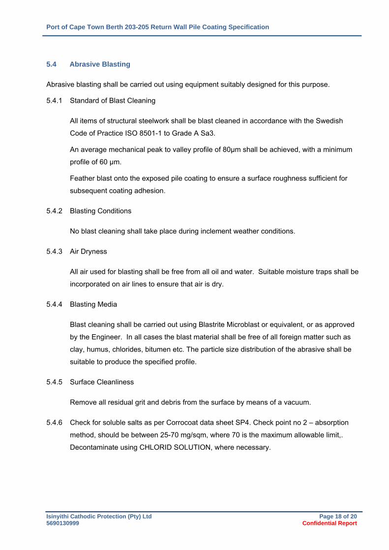
5.4 Abrasive Blasting
Abrasive blasting shall be carried out using equipment suitably designed for this purpose.
5.4.1 Standard of Blast Cleaning
All items of structural steelwork shall be blast cleaned in accordance with the Swedish
Code of Practice ISO 8501-1 to Grade A Sa3.
An average mechanical peak to valley profile of 80μm shall be achieved, with a minimum
profile of 60 μm.
Feather blast onto the exposed pile coating to ensure a surface roughness sufficient for
subsequent coating adhesion.
5.4.2 Blasting Conditions
No blast cleaning shall take place during inclement weather conditions.
5.4.3 Air Dryness
All air used for blasting shall be free from all oil and water. Suitable moisture traps shall be
incorporated on air lines to ensure that air is dry.
5.4.4 Blasting Media
Blast cleaning shall be carried out using Blastrite Microblast or equivalent, or as approved
by the Engineer. In all cases the blast material shall be free of all foreign matter such as
clay, humus, chlorides, bitumen etc. The particle size distribution of the abrasive shall be
suitable to produce the specified profile.
5.4.5 Surface Cleanliness
Remove all residual grit and debris from the surface by means of a vacuum.
5.4.6 Check for soluble salts as per Corrocoat data sheet SP4. Check point no 2 – absorption
method, should be between 25-70 mg/sqm, where 70 is the maximum allowable limit,.
Decontaminate using CHLORID SOLUTION, where necessary.
Port of Cape Town Berth 203-205 Return Wall Pile Coating Specification
Isinyithi Cathodic Protection (Pty) Ltd Page 19 of 20 5690130999 Confidential Report
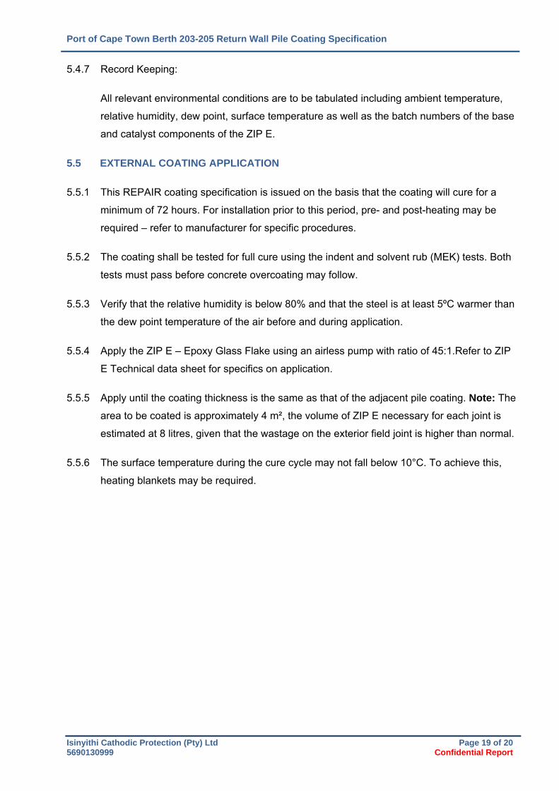
5.4.7 Record Keeping:
All relevant environmental conditions are to be tabulated including ambient temperature,
relative humidity, dew point, surface temperature as well as the batch numbers of the base
and catalyst components of the ZIP E.
5.5 EXTERNAL COATING APPLICATION
5.5.1 This REPAIR coating specification is issued on the basis that the coating will cure for a
minimum of 72 hours. For installation prior to this period, pre- and post-heating may be
required – refer to manufacturer for specific procedures.
5.5.2 The coating shall be tested for full cure using the indent and solvent rub (MEK) tests. Both
tests must pass before concrete overcoating may follow.
5.5.3 Verify that the relative humidity is below 80% and that the steel is at least 5ºC warmer than
the dew point temperature of the air before and during application.
5.5.4 Apply the ZIP E – Epoxy Glass Flake using an airless pump with ratio of 45:1.Refer to ZIP
E Technical data sheet for specifics on application.
5.5.5 Apply until the coating thickness is the same as that of the adjacent pile coating. Note: The
area to be coated is approximately 4 m², the volume of ZIP E necessary for each joint is
estimated at 8 litres, given that the wastage on the exterior field joint is higher than normal.
5.5.6 The surface temperature during the cure cycle may not fall below 10°C. To achieve this,
heating blankets may be required.
Port of Cape Town Berth 203-205 Return Wall Pile Coating Specification
Isinyithi Cathodic Protection (Pty) Ltd Page 20 of 20 5690130999 Confidential Report
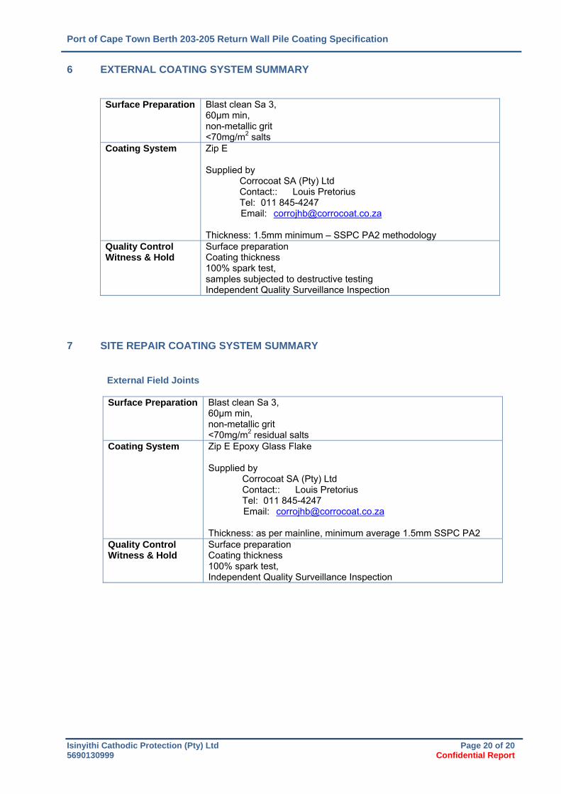
6 EXTERNAL COATING SYSTEM SUMMARY
Surface Preparation Blast clean Sa 3, 60μm min, non-metallic grit <70mg/m2 salts
Coating System Zip E Supplied by
Corrocoat SA (Pty) Ltd Contact:: Louis Pretorius Tel: 011 845-4247 Email: [email protected]
Thickness: 1.5mm minimum – SSPC PA2 methodology
Quality Control Witness & Hold
Surface preparation Coating thickness 100% spark test, samples subjected to destructive testing Independent Quality Surveillance Inspection
7 SITE REPAIR COATING SYSTEM SUMMARY
External Field Joints Surface Preparation Blast clean Sa 3,
60μm min, non-metallic grit <70mg/m2 residual salts
Coating System Zip E Epoxy Glass Flake Supplied by
Corrocoat SA (Pty) Ltd Contact:: Louis Pretorius Tel: 011 845-4247 Email: [email protected]
Thickness: as per mainline, minimum average 1.5mm SSPC PA2
Quality Control Witness & Hold
Surface preparation Coating thickness 100% spark test, Independent Quality Surveillance Inspection
TRANSNET SOC LTD DCT BERTHS 203 TO 205 – RECONSTRUCTION, DEEPENING AND LENGTHENING
PORT OF DURBAN
SPECIFICATION – CORROSION PROTECTION
1370‐CO‐000‐C‐SPC‐0017 Rev T‐0B Annexures April 2017
Page | A2
ANNEXURE 2: ISINYITHI CATHODIC PROTECTION SPECIFICATIONS: PORT OF
DURBAN BERTHS 203 TO 205 RETURN WALL STEEL PILES 5690/130999 GALVANIC
ANODES SPECIFICATION
C O N F I D E N T I A L R E P O R T
CLIENT : ZAA Engineering Projects & Naval Architecture
PROJECT : Port of Durban Berths 203 - 205 Return Wall
SCOPE : SACRIFICIAL ANODE SPECIFICATION
DATE : JUNE 2016
REF : 5890/130999 For construction
Responsibility rests with the reader to verify that this is the latest revision
Report by: _____________________ F L Bradfield
Internal Review: _____________________
N C Webb
Isinyithi Cathodic Protection (Pty) Ltd Page 2 of 8 5890130999.docx Confidential Report
Reports are submitted to clients on a confidential basis;
No reference to the work or test results in any manner will be discussed or made public without
written authorisation from the client;
All work is considered proprietary property of the client and is maintained by ICP as such.
Disclaimer: Responsibility rests with the reader to verify the latest revision of the report.
Isinyithi Cathodic Protection (Pty) Ltd Page 3 of 8 5890130999.docx Confidential Report
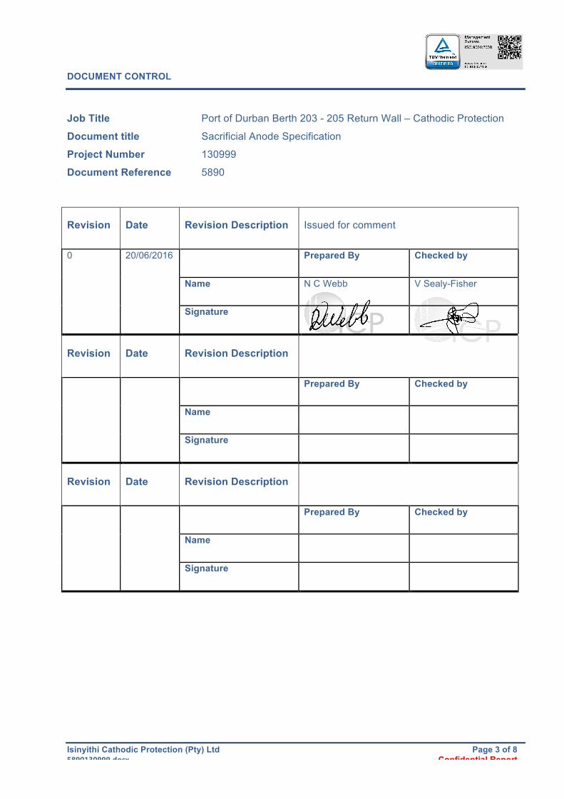
DOCUMENT CONTROL
Job Title Port of Durban Berth 203 - 205 Return Wall – Cathodic Protection
Document title Sacrificial Anode Specification
Project Number 130999
Document Reference 5890
Revision Date Revision Description Issued for comment
0 20/06/2016 Prepared By Checked by
Name N C Webb V Sealy-Fisher
Signature
Revision Date Revision Description
Prepared By Checked by
Name
Signature
Revision Date Revision Description
Prepared By Checked by
Name
Signature
Isinyithi Cathodic Protection (Pty) Ltd Page 4 of 8 5890130999.docx Confidential Report
TABLE OF CONTENTS
1. INTRODUCTION ........................................................................................................................................ 5 2. SUMMARY OF PARAMETERS ................................................................................................................. 6 3. SELECTION OF APPLICABLE STANDARDS ........................................................................................... 7 4. DESIGN SUMMARY OF CORROSION PROTECTION SYSTEM ............................................................ 8
Port of Durban Berth 203 - 205 Return Wall– Cathodic Protection
Isinyithi Cathodic Protection (Pty) Ltd Page 5 of 8 5890130999.docx Confidential Report
1. INTRODUCTION
The Return Wall for the Port of Durban Berth 203 - 205 deepening comprises cellular coffer dam
type caissons formed from steel sheet piles. The majority of the piles will be driven through existing
soils, after which the sea face will be dredged.
The caissons are 23m outer diameter, using 508mm straight sheet piles. The total pile length is
31m. The top 3,2m of the sheet pile will be encased in a concrete capping beam which extends to
500mm below LAT.
The corrosion protection system will comprise a combination of sacrificial steel corrosion
allowance, glass flake reinforced epoxy coating and sacrificial anode cathodic protection.
This specification covers the supply of Aluminium - Zinc - Indium anodes for cathodic protection.
Port of Durban Berth 203 - 205 Return Wall– Cathodic Protection
Isinyithi Cathodic Protection (Pty) Ltd Page 6 of 8 5890130999.docx Confidential Report
2. SUMMARY OF PARAMETERS
a. The design life of the corrosion protection system is 50 years.
b. Sacrificial anode material selection favours Aluminium anodes rather than Zinc anodes due
to both cost and weight considerations.
c. All electrical connections between anodes and the pile will be welded. Bolted connections
are only for mounting purposes.
d. As the anodes can only be installed after dredging, angle mounting brackets are proposed
with a welded electrical connection above the water line.
e. Anodes will be installed prior to casting of the pile cap.
f. The piles will be fully coated on the sea face to reduce CP current requirements and enable
the 50-year design life without anode replacement.
g. The top section of all piles will be coated on both faces to 1m below the level of the capping
beam to provide supplementary protection in the intertidal zone and prevent localised
corrosion of the steel adjacent to the encasement of the capping beam.
Port of Durban Berth 203 - 205 Return Wall– Cathodic Protection
Isinyithi Cathodic Protection (Pty) Ltd Page 7 of 8 5890130999.docx Confidential Report
3. SELECTION OF APPLICABLE STANDARDS
The cathodic protection design is based on the requirements of SANS ISO 15589-2 and EN ISO
13174 for harbour installations and takes into consideration the requirements for protection against
ALWC (Accelerated Low Water Corrosion)
For this application, bareness and breakdown factors are used for coated steel which has been
subject to piling. This is an unusual requirement as the piles are being installed prior to dig-out.
Although underwater coating repairs are possible, the extent and efficacy of these repairs cannot
be predicted.
Port of Durban Berth 203 - 205 Return Wall– Cathodic Protection
Isinyithi Cathodic Protection (Pty) Ltd Page 8 of 8 5890130999.docx Confidential Report
4. DESIGN SUMMARY OF CORROSION PROTECTION SYSTEM
Refer to drawing 1370-CO-070-C-DWG-0003-01
a. Each anode is 2000mm long x 190/140mm wide (trapezoidal) x 120mm thick cast onto an
offset steel "I" strap 50 x 6mm
b. The anode straps are designed to bolt onto brackets welded to each sheet pile.
c. A 50 x 6 x 4450mm continuity strap is welded to the top of the insert after casting the anode
in order to provide electrical continuity to the pile.
d. There is one anode per pile for each pile exposed to the sea.
e. The anode is installed such that the top of the anode is 1m below the bottom of the capping
beam.
f. The rear face of the anode as well as the protruding steel sections shall be coated with the
same epoxy/glass flake coating as the external surface of the pile.
g. The total net anode mass requirement is 95kg per pile with a utilisation factor of 80%.
h. Anodes will be manufactured in accordance with SANS ISO 15589-2: 2009 (sled anodes)
i. Electrochemical capacity: 2300 A.hrs/kg
ii. Driving potential: 1050mVAg/AgCl
i. Quality control requirements will be:
i. Chemical analysis: each heat
ii. Dimensional tolerance: each anode
iii. Electrochemical testing: prequalification plus 1 per 15 tonnes
iv. Destructive testing: prequalification plus 1 per 15 tonnes.
TRANSNET SOC LTD DCT BERTHS 203 TO 205 – RECONSTRUCTION, DEEPENING AND LENGTHENING
PORT OF DURBAN
SPECIFICATION – CORROSION PROTECTION
1370‐CO‐000‐C‐SPC‐0017 Rev T‐0B Annexures April 2017
Page | A3
ANNEXURE 3: DESIGN REPORT ZAA 1370‐RPT‐063
TRANSNET SOC LTD
DEEPENING OF BERTHS 203 TO 205
PORT OF DURBAN
CORROSION PROTECTION DESIGN REPORT
ZAA 1370 | RPT | 063 REV A
30 October 2015
TRANSNET SOC LTD DEEPENING OF BERTHS 203 TO 205, PORT OF DURBAN
CORROSION PROTECTION DESIGN REPORT
ZAA 1370 | RPT | 063 Rev A October 2015
REVISIONS
REV DATE DESCRIPTION DESIGNED
BY
CHECKED
BY
APPROVED
BY
A 30 October 2015 Issue to Client NW NW JZ
AUTHORISATION
AUTHORISED BY NAME SIGNATURE DATE
DIRECTOR J ZIETSMAN Pr Eng
30 October 2015
This document, including all design and information therein, is Confidential Intellectual Property of ZAA Engineering.
Copyright and all other rights are reserved by ZAA Engineering.
This document may only be used for its intended purpose.
C O N F I D E N T I A L R E P O R T
CLIENT : ZAA Engineering Projects & Naval Architecture
PROJECT : Port of Durban Berths 203 - 205 Return Wall
SCOPE : CATHODIC PROTECTION DESIGN REPORT
DATE : October 2015
REF : 5687/130999[1] For approval
Responsibility rests with the reader to verify that this is the latest revision
Report by: _____________________
F L Bradfield
Internal Review: _____________________
N C Webb
Isinyithi Cathodic Protection (Pty) Ltd Page 2 of 9 5687130999 [1] Confidential Report
Reports are submitted to clients on a confidential basis;
No reference to the work or test results in any manner will be discussed or made public without
written authorisation from the client;
All work is considered proprietary property of the client and is maintained by ICP as such.
Disclaimer: Responsibility rests with the reader to verify the latest revision of the report.
Isinyithi Cathodic Protection (Pty) Ltd Page 3 of 9 5687130999 [1] Confidential Report
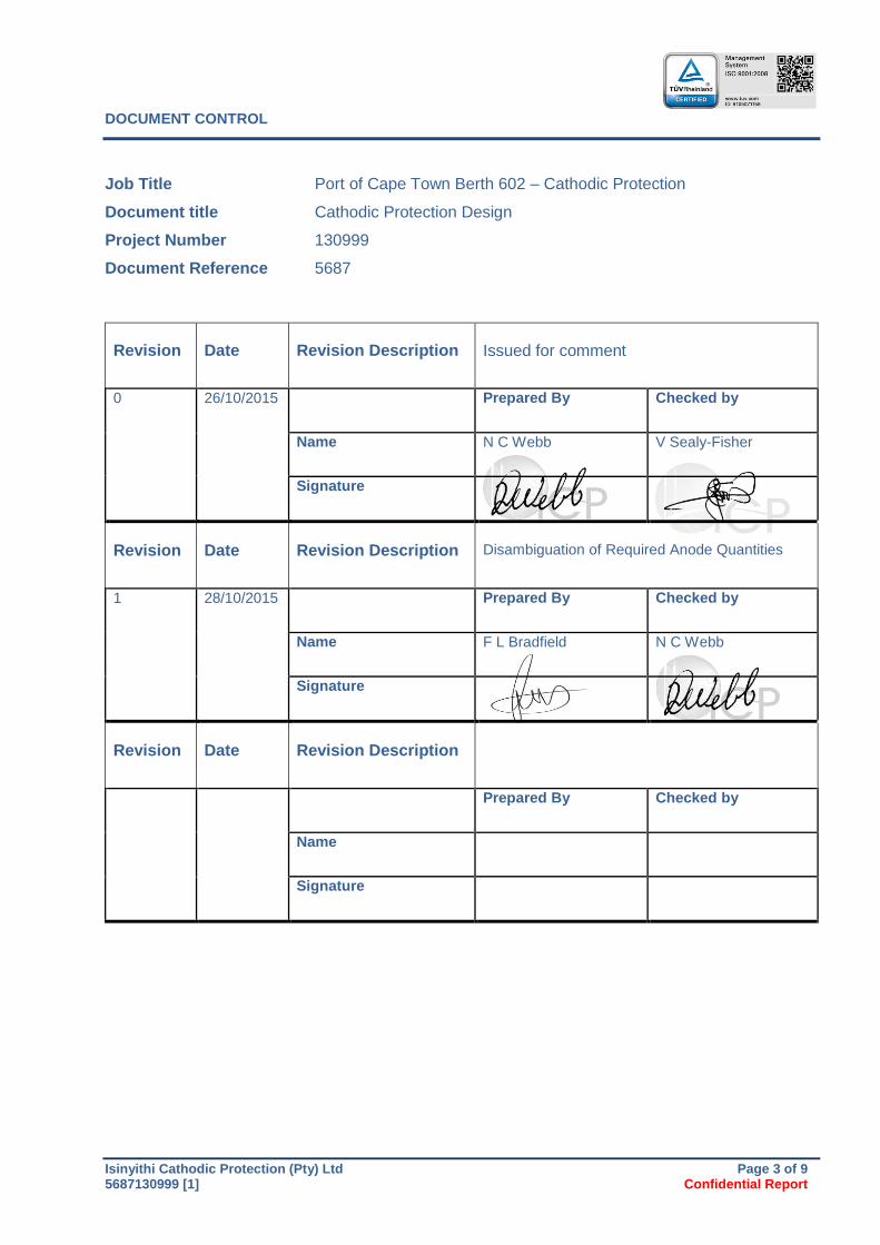
DOCUMENT CONTROL
Job Title Port of Cape Town Berth 602 – Cathodic Protection
Document title Cathodic Protection Design
Project Number 130999
Document Reference 5687
Revision Date Revision Description Issued for comment
0 26/10/2015 Prepared By Checked by
Name N C Webb V Sealy-Fisher
Signature
Revision Date Revision Description Disambiguation of Required Anode Quantities
1 28/10/2015 Prepared By Checked by
Name F L Bradfield N C Webb
Signature
Revision Date Revision Description
Prepared By Checked by
Name
Signature
Isinyithi Cathodic Protection (Pty) Ltd Page 4 of 9 5687130999 [1] Confidential Report
TABLE OF CONTENTS
1. INTRODUCTION ...................................................................................................................... 5
2. SUMMARY OF PARAMETERS ................................................................................................ 6
3. SELECTION OF APPLICABLE STANDARDS .......................................................................... 7
4. DESIGN SUMMARY OF CORROSION PROTECTION SYSTEM ............................................. 8
APPENDIX 1: Table of Calculations ................................................................................................ 9
Port of Cape Town Berth 602 – Cathodic Protection
Isinyithi Cathodic Protection (Pty) Ltd Page 5 of 9 5687130999 [1] Confidential Report
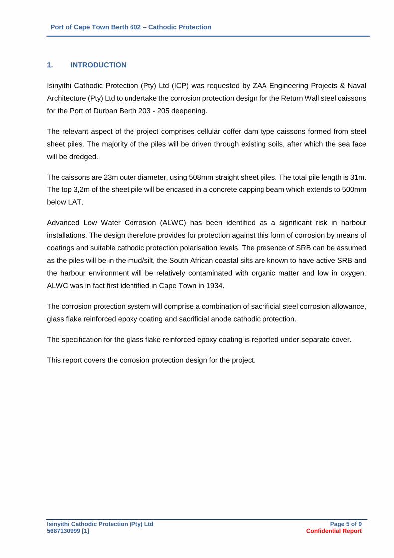
1. INTRODUCTION
Isinyithi Cathodic Protection (Pty) Ltd (ICP) was requested by ZAA Engineering Projects & Naval
Architecture (Pty) Ltd to undertake the corrosion protection design for the Return Wall steel caissons
for the Port of Durban Berth 203 - 205 deepening.
The relevant aspect of the project comprises cellular coffer dam type caissons formed from steel
sheet piles. The majority of the piles will be driven through existing soils, after which the sea face
will be dredged.
The caissons are 23m outer diameter, using 508mm straight sheet piles. The total pile length is 31m.
The top 3,2m of the sheet pile will be encased in a concrete capping beam which extends to 500mm
below LAT.
Advanced Low Water Corrosion (ALWC) has been identified as a significant risk in harbour
installations. The design therefore provides for protection against this form of corrosion by means of
coatings and suitable cathodic protection polarisation levels. The presence of SRB can be assumed
as the piles will be in the mud/silt, the South African coastal silts are known to have active SRB and
the harbour environment will be relatively contaminated with organic matter and low in oxygen.
ALWC was in fact first identified in Cape Town in 1934.
The corrosion protection system will comprise a combination of sacrificial steel corrosion allowance,
glass flake reinforced epoxy coating and sacrificial anode cathodic protection.
The specification for the glass flake reinforced epoxy coating is reported under separate cover.
This report covers the corrosion protection design for the project.
Port of Cape Town Berth 602 – Cathodic Protection
Isinyithi Cathodic Protection (Pty) Ltd Page 6 of 9 5687130999 [1] Confidential Report
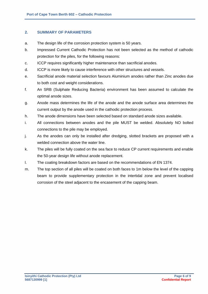
2. SUMMARY OF PARAMETERS
a. The design life of the corrosion protection system is 50 years.
b. Impressed Current Cathodic Protection has not been selected as the method of cathodic
protection for the piles, for the following reasons:
c. ICCP requires significantly higher maintenance than sacrificial anodes.
d. ICCP is more likely to cause interference with other structures and vessels.
e. Sacrificial anode material selection favours Aluminium anodes rather than Zinc anodes due
to both cost and weight considerations.
f. An SRB (Sulphate Reducing Bacteria) environment has been assumed to calculate the
optimal anode sizes.
g. Anode mass determines the life of the anode and the anode surface area determines the
current output by the anode used in the cathodic protection process.
h. The anode dimensions have been selected based on standard anode sizes available.
i. All connections between anodes and the pile MUST be welded. Absolutely NO bolted
connections to the pile may be employed.
j. As the anodes can only be installed after dredging, slotted brackets are proposed with a
welded connection above the water line.
k. The piles will be fully coated on the sea face to reduce CP current requirements and enable
the 50-year design life without anode replacement.
l. The coating breakdown factors are based on the recommendations of EN 1374.
m. The top section of all piles will be coated on both faces to 1m below the level of the capping
beam to provide supplementary protection in the intertidal zone and prevent localised
corrosion of the steel adjacent to the encasement of the capping beam.
Port of Cape Town Berth 602 – Cathodic Protection
Isinyithi Cathodic Protection (Pty) Ltd Page 7 of 9 5687130999 [1] Confidential Report
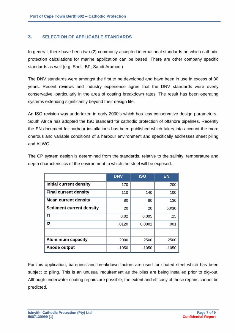
3. SELECTION OF APPLICABLE STANDARDS
In general, there have been two (2) commonly accepted international standards on which cathodic
protection calculations for marine application can be based. There are other company specific
standards as well (e.g. Shell, BP, Saudi Aramco )
The DNV standards were amongst the first to be developed and have been in use in excess of 30
years. Recent reviews and industry experience agree that the DNV standards were overly
conservative, particularly in the area of coating breakdown rates. The result has been operating
systems extending significantly beyond their design life.
An ISO revision was undertaken in early 2000’s which has less conservative design parameters..
South Africa has adopted the ISO standard for cathodic protection of offshore pipelines. Recently
the EN document for harbour installations has been published which takes into account the more
onerous and variable conditions of a harbour environment and specifically addresses sheet piling
and ALWC.
The CP system design is determined from the standards, relative to the salinity, temperature and
depth characteristics of the environment to which the steel will be exposed.
DNV ISO EN
Initial current density 170 200
Final current density 110 140 100
Mean current density 80 80 130
Sediment current density 20 20 50/30
f1 0.02 0.005 .25
f2 .0120 0.0002 .001
Aluminium capacity 2000 2500 2500
Anode output -1050 -1050 -1050
For this application, bareness and breakdown factors are used for coated steel which has been
subject to piling. This is an unusual requirement as the piles are being installed prior to dig-out.
Although underwater coating repairs are possible, the extent and efficacy of these repairs cannot be
predicted.
Port of Cape Town Berth 602 – Cathodic Protection
Isinyithi Cathodic Protection (Pty) Ltd Page 8 of 9 5687130999 [1] Confidential Report
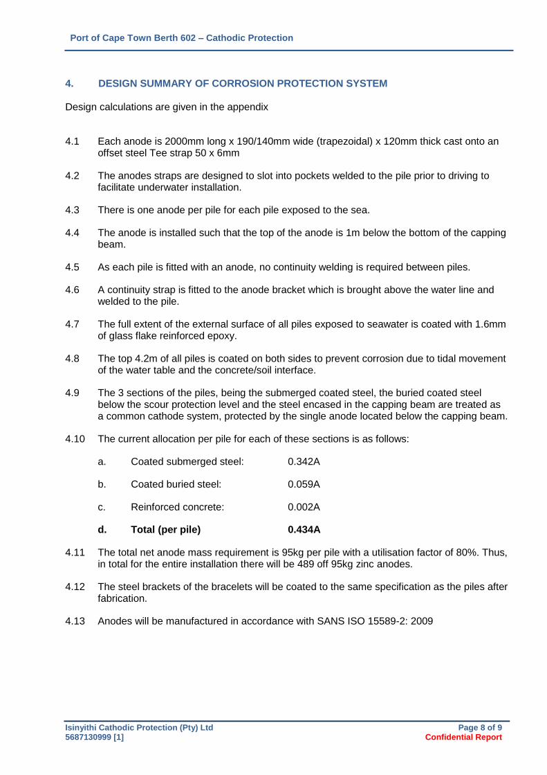
4. DESIGN SUMMARY OF CORROSION PROTECTION SYSTEM
Design calculations are given in the appendix
4.1 Each anode is 2000mm long x 190/140mm wide (trapezoidal) x 120mm thick cast onto an offset steel Tee strap 50 x 6mm
4.2 The anodes straps are designed to slot into pockets welded to the pile prior to driving to facilitate underwater installation.
4.3 There is one anode per pile for each pile exposed to the sea.
4.4 The anode is installed such that the top of the anode is 1m below the bottom of the capping beam.
4.5 As each pile is fitted with an anode, no continuity welding is required between piles.
4.6 A continuity strap is fitted to the anode bracket which is brought above the water line and welded to the pile.
4.7 The full extent of the external surface of all piles exposed to seawater is coated with 1.6mm of glass flake reinforced epoxy.
4.8 The top 4.2m of all piles is coated on both sides to prevent corrosion due to tidal movement of the water table and the concrete/soil interface.
4.9 The 3 sections of the piles, being the submerged coated steel, the buried coated steel below the scour protection level and the steel encased in the capping beam are treated as a common cathode system, protected by the single anode located below the capping beam.
4.10 The current allocation per pile for each of these sections is as follows:
a. Coated submerged steel: 0.342A
b. Coated buried steel: 0.059A
c. Reinforced concrete: 0.002A
d. Total (per pile) 0.434A
4.11 The total net anode mass requirement is 95kg per pile with a utilisation factor of 80%. Thus, in total for the entire installation there will be 489 off 95kg zinc anodes.
4.12 The steel brackets of the bracelets will be coated to the same specification as the piles after fabrication.
4.13 Anodes will be manufactured in accordance with SANS ISO 15589-2: 2009
Port of Cape Town Berth 602 – Cathodic Protection
Isinyithi Cathodic Protection (Pty) Ltd Page 9 of 9 5687130999 [1] Confidential Report
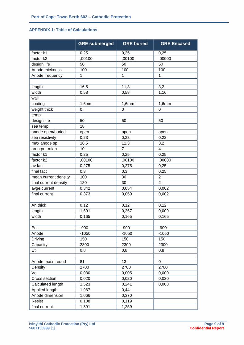
APPENDIX 1: Table of Calculations
GRE submerged GRE buried GRE Encased
factor k1 0,25 0,25 0,25
factor k2 ,00100 ,00100 ,00000
design life 50 50 50
Anode thickness 100 100 100
Anode frequency 1 1 1
length 16,5 11,3 3,2
width 0,58 0,58 1,16
wall
coating 1,6mm 1,6mm 1,6mm
weight thick 0 0 0
temp
design life 50 50 50
sea temp 18
anode open/buried open open open
sea resistivity 0,23 0,23 0,23
max anode sp 16,5 11,3 3,2
area per midp 10 7 4
factor k1 0,25 0,25 0,25
factor k2 ,00100 ,00100 ,00000
av fact 0,275 0,275 0,25
final fact 0,3 0,3 0,25
mean current density 100 30 2
final current density 130 30 2
avge current 0,342 0,054 0,002
final current 0,373 0,059 0,002
An thick 0,12 0,12 0,12
length 1,691 0,267 0,009
width 0,165 0,165 0,165
Pot -900 -900 -900
Anode -1050 -1050 -1050
Driving 150 150 150
Capacity 2300 2300 2300
Util 0,8 0,8 0,8
Anode mass requd 81 13 0
Density 2700 2700 2700
Vol 0,030 0,005 0,000
Cross section 0,020 0,020 0,020
Calculated length 1,523 0,241 0,008
Applied length 1,967 0,44
Anode dimension 1,066 0,370
Resist 0,108 0,119
final current 1,391 1,259