TRANSMUTATION FUEL CYCLEfrc.gatech.edu/wp-content/uploads/sites/338/2016/02/SABR... ·...
12
FUEL CYCLE AND MANAGEMENT KEYWORDS: transmutation, fuel cycle, actinide-burning fuel cycle TRANSMUTATION FUEL CYCLE ANALYSES OF THE SABR FISSION-FUSION HYBRID BURNER REACTOR FOR TRANSURANIC AND MINOR ACTINIDE FUELS C. M. SOMMER,W. M. STACEY,* B. PETROVIC, and C. L. STEWART Georgia Institute of Technology, Nuclear and Radiological Engineering Atlanta, Georgia 30332 Received May 6, 2011 Accepted for Publication July 9, 2012 Fuel cycle analyses of the transmutation of (a) all of the transuranics (TRUs) in light water reactor (LWR) spent nuclear fuel (SNF) and of (b) the minor actinides (MAs) remaining in SNF (after separation of much of the plutonium for starting up fast reactors) have been per- formed for the conceptual subcritical advanced burner reactor (SABR) fission-fusion hybrid sodium-cooled fast burner reactor. Both metallic and oxide burner reactor fuels were considered, and the effect of clad radiation damage limit on fuel residence time was investigated. For a radiation damage limit of 200 displacements per atom, the support ratio (LWR power/SABR power) for transmuting all of the TRUs produced by LWRs is 3/1, and for transmuting just the MAs produced by LWRs the support ratio is 25/1. The reduction in high-level waste repository capacity required due to this transmutation is a factor of 10, based on a decay heat at a 100 000-yr limit on capacity. I. INTRODUCTION At the present rate of nuclear power generation in the United States, enough spent fuel will have accumulated to fill a Yucca Mountain–type high-level radioactive waste repository ~ HLWR! by the year 2020 ~ Ref. 1!. The fore- cast for increased power generation by nuclear power in the next 30 yr and over the coming century magnifies the issue of spent nuclear fuel ~SNF ! disposal. Between 2007 and 2010 the U.S. Nuclear Regulatory Commission ~ NRC! accepted applications for 26 new light water reactors ~ LWRs!, and the NRC expects applications for another 5 reactors in 2011 ~ Ref. 2!. These 31 reactors would in- crease the current nuclear power output of the United States by ;30%, increasing the amount of discharge fuel needed to be stored in geological repositories by a similar amount. Until very recently, the reference U.S. option for disposal of SNF was ~a! initially on-site storage and ~ b! shipping the fuel to a geological repository where it would be interred forever. With this predicted increase in nuclear power, a new geological repository of the same size as Yucca Mountain would be needed every 45 yr. A second option for spent fuel disposal is to intro- duce a multistrata fuel cycle in which following ~a! initial on-site storage, ~ b! the spent fuel from LWRs is recycled in advanced burner reactor systems to burn essentially all the long-lived actinides that determine the requirement to demonstrate performance for a 100 000-yr interment, and ~c! then only the fission products and trace amounts of actinides are sent to long-term HLWRs. The multi- strata fuel cycle would not replace geological reposito- ries but would significantly reduce the number of HLWRs that are necessary. Such multistrata fuel cycles have been widely stud- ied for critical advanced burner reactors and for subcrit- ical reactors supported by an external source of neutrons provided by an accelerator target embedded in the core 3 and examined to a lesser extent for subcritical reactors supported by fusion neutron sources. 4–7 *E-mail: [email protected] 274 NUCLEAR TECHNOLOGY VOL. 182 JUNE 2013
Transcript of TRANSMUTATION FUEL CYCLEfrc.gatech.edu/wp-content/uploads/sites/338/2016/02/SABR... ·...

FUEL CYCLE ANDMANAGEMENT
KEYWORDS: transmutation, fuelcycle, actinide-burning fuel cycle
TRANSMUTATION FUEL CYCLEANALYSES OF THE SABRFISSION-FUSION HYBRID BURNERREACTOR FOR TRANSURANIC ANDMINOR ACTINIDE FUELSC. M. SOMMER, W. M. STACEY,* B. PETROVIC, and C. L. STEWART
Georgia Institute of Technology, Nuclear and Radiological EngineeringAtlanta, Georgia 30332
Received May 6, 2011Accepted for Publication July 9, 2012
Fuel cycle analyses of the transmutation of (a) all ofthe transuranics (TRUs) in light water reactor (LWR)spent nuclear fuel (SNF) and of (b) the minor actinides(MAs) remaining in SNF (after separation of much of theplutonium for starting up fast reactors) have been per-formed for the conceptual subcritical advanced burnerreactor (SABR) fission-fusion hybrid sodium-cooled fastburner reactor. Both metallic and oxide burner reactorfuels were considered, and the effect of clad radiation
damage limit on fuel residence time was investigated.For a radiation damage limit of 200 displacements peratom, the support ratio (LWR power/SABR power) fortransmuting all of the TRUs produced by LWRs is 3/1,and for transmuting just the MAs produced by LWRs thesupport ratio is 25/1. The reduction in high-level wasterepository capacity required due to this transmutation isa factor of 10, based on a decay heat at a 100 000-yr limiton capacity.
I. INTRODUCTION
At the present rate of nuclear power generation in theUnited States, enough spent fuel will have accumulatedto fill a Yucca Mountain–type high-level radioactive wasterepository ~HLWR! by the year 2020 ~Ref. 1!. The fore-cast for increased power generation by nuclear power inthe next 30 yr and over the coming century magnifies theissue of spent nuclear fuel ~SNF! disposal. Between 2007and 2010 the U.S. Nuclear Regulatory Commission ~NRC!accepted applications for 26 new light water reactors~LWRs!, and the NRC expects applications for another 5reactors in 2011 ~Ref. 2!. These 31 reactors would in-crease the current nuclear power output of the UnitedStates by;30%, increasing the amount of discharge fuelneeded to be stored in geological repositories by a similaramount.
Until very recently, the reference U.S. option fordisposal of SNF was ~a! initially on-site storage and
~b! shipping the fuel to a geological repository where itwould be interred forever. With this predicted increase innuclear power, a new geological repository of the samesize as Yucca Mountain would be needed every 45 yr.
A second option for spent fuel disposal is to intro-duce a multistrata fuel cycle in which following ~a! initialon-site storage, ~b! the spent fuel from LWRs is recycledin advanced burner reactor systems to burn essentially allthe long-lived actinides that determine the requirementto demonstrate performance for a 100 000-yr interment,and ~c! then only the fission products and trace amountsof actinides are sent to long-term HLWRs. The multi-strata fuel cycle would not replace geological reposito-ries but would significantly reduce the number of HLWRsthat are necessary.
Such multistrata fuel cycles have been widely stud-ied for critical advanced burner reactors and for subcrit-ical reactors supported by an external source of neutronsprovided by an accelerator target embedded in the core3
and examined to a lesser extent for subcritical reactorssupported by fusion neutron sources.4–7*E-mail: [email protected]
274 NUCLEAR TECHNOLOGY VOL. 182 JUNE 2013
Utilizing subcritical reactors with a variable-strengthfusion neutron source removes the criticality constrainton fuel residence time and allows for the fuel to remainin the reactor until the radiation damage limit is reached,which should result in fewer reprocessing steps and ul-timately fewer repositories than would be needed in amultistrata fuel cycle utilizing critical burner reactors.The subcritical operation also provides an extra marginof safety to prompt critical, which should allow the burnerreactor to be fueled with 100% transuranics ~TRUs!, in-stead of ;20% TRUs for critical reactors, which shouldresult in fewer subcritical than critical burner reactorsbeing necessary to support a given fleet of LWRs. On theother hand, the subcritical reactor with a fusion neutronsource would be more complex and expensive than acomparable critical reactor.
A fission-fusion hybrid is a subcritical fission reac-tor supplemented by a fusion neutron source. The fusionneutron source is chosen for three reasons. First, fusion isone of only two options for a copious neutron source;second, the fusion neutron source strength is variable andcan be increased or decreased to maintain a desired fis-sion or thermal power level independent of the changesin reactivity throughout the cycle; and third, the fusionneutron source is a distributed neutron source capable ofirradiating a larger volume of fuel than a point neutronsource such as an accelerator target, the other option forsuch a large neutron source.8
This paper focuses on various transmutation fuel cy-cles in the subcritical advanced burner reactor9 ~SABR!,a fission-fusion hybrid reactor with a fusion neutron sourcebased on ITER physics and technology10 combined witha fast burner reactor based on the leading sodium-cooledfast reactor technology. Fuel residence time is limited inthese fuel cycles by the radiation damage to the structuralmaterials. This study examines three different fuel types@~a! TRUs from LWRs in a metallic fuel, ~b! minor acti-
nide ~MA!-rich TRUs from which some of the Pu hasbeen removed in a metallic fuel, and ~c! MA-rich TRUsin an oxide fuel# for transmutation in the SABR.
II. SABR DESIGN
II.A. Overview
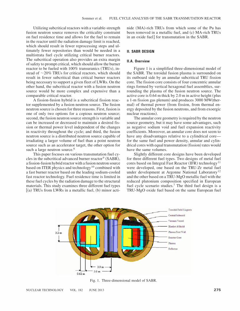
Figure 1 is a simplified three-dimensional model ofthe SABR. The toroidal fusion plasma is surrounded onits outboard side by an annular subcritical TRU fissioncore. The fission core consists of four concentric annularrings formed by vertical hexagonal fuel assemblies, sur-rounding the plasma of the fusion neutron source. Theactive core is 0.64 m thick by 2.0 m in active height ~plusa 1-m fission gas plenum! and produces 3000 MW~ther-mal! of thermal power ~from fission, from thermal en-ergy deposited by the fusion neutrons, and from exoergicnuclear reactions!.
The annular core geometry is required by the neutronsource geometry, but it may have some advantages, suchas negative sodium void and fuel expansion reactivitycoefficients. Moreover, an annular core does not seem tohave any disadvantages relative to a cylindrical core—for the same fuel and power density, annular and cylin-drical cores with equal transmutation ~fission! rates wouldhave the same volumes.
Slightly different core designs have been developedfor three different fuel types. Two designs of metal fuelcores based on Integral Fast Reactor ~IFR! technology11
were developed, one based on the TRU-Zr metal fuelunder development at Argonne National Laboratory12
and the other based on a TRU-MgO metallic fuel with thereduced plutonium composition specified in Europeanfuel cycle scenario studies.7 The third fuel design is aTRU-MgO oxide fuel based on the same European fuel
Fig. 1. Three-dimensional model of SABR.
Sommer et al. FUEL CYCLE ANALYSIS OF THE SABR TRANSMUTATION REACTOR
NUCLEAR TECHNOLOGY VOL. 182 JUNE 2013 275

composition. The Argonne TRU-Zr fuel composition isrepresentative of the spent fuel discharged from LWRs,while the European TRU-MgO fuel composition is rep-resentative of a MA-rich fuel that would result after set-ting aside some of the plutonium from LWR spent fuelfor future use in starting up fast reactors.
The plasma and core region are surrounded by a15-cm lithium oxysilicate blanket for tritium production,followed by a steel reflector and a multilayered shield tocapture neutrons and gamma rays and to protect the to-roidal field magnets from radiation damage.
A detailed geometric cross section of SABR, illus-trating the locations of these various regions, is shown inthe r-z neutronics computation model of SABR shown inFig. 2. As a point of reference, SABR, with a plasmamajor radius,4 m, is about half the size ~by volume! ofITER ~Ref. 9!.
II.B. Fuel Element and Fuel Assembly Design
Originally, SABR was designed9 for the TRU-Zrmetal fuel being developed by Argonne National Labo-ratory.12 The fuel is composed of 40Zr-40Pu-10Np-10Am by weight percent. The isotopic composition of
the fuel is given in Table I. The metallic fuel form waschosen because it has a high thermal conductivity, hasthe possibility of achieving the inherent safety character-istics of the IFR ~Ref. 11!, and has a fuel cycle in whichthe plutonium is never separated from the higher actinides.
The fuel pins in SABR are based on a standard IFR-type metallic fuel pin design but coated with an electricalinsulator to reduce the magnetohydrodynamic pressuredrops associated with sodium coolant in a magnetic field.9
~The design power density was significantly lower thanthe usual IFR designs, and the effect of the insulator onthermal performance was taken into account.!The SABRfuel pins based on the composition in Table I are shownin Figs. 3 and 4. The basic SABR fuel assembly with 271of these fuel pins is shown in Fig. 5. The core consists of918 such fuel assemblies arranged in four annular rings.
II.C. SABR Fuel Assemblies for European MA-Rich Fuel
The Karlsruhe Institute of Technology is examininga fuel cycle scenario of interest to some European coun-tries,7 in which the plutonium is removed from spentfuel and set aside for future use, leaving the MA-richfuel type shown in Table II. This fuel composition was
Fig. 2. SABR r-z neutronics computational model.
Sommer et al. FUEL CYCLE ANALYSIS OF THE SABR TRANSMUTATION REACTOR
276 NUCLEAR TECHNOLOGY VOL. 182 JUNE 2013

selected8 to have a minimal reactivity change with burnupto accommodate a subcritical burner reactor with anaccelerator neutron source. The fuel consists of 45.7%plutonium and 54.3% MAs in a magnesium oxide matrix.
Two fuel types using the European fuel compositionof Table II were examined. The first fuel type was a metalfuel. The same fuel pin and fuel assembly design de-scribed in Sec. II.B for the original SABR fuel were used,but with the fuel composition of Table II instead of that ofTable I, and an oxide matrix rather than a zirconiummatrix.
An oxide fuel with the MA-rich composition ofTable II was also considered. Since the oxide fuel has a
lower heavy metal density than metallic fuel, a larger fuelvolume is needed to operate in the same range of keff asthe metal fuel designs. The SABR fuel pins and fuelassemblies were slightly redesigned to accommodate theoxide fuel. The European fuel pin design from the EFITstudy8 was used for the oxide fuel, resulting in the oxidefuel pin having a larger pin diameter and a smaller coolant-to-fuel-volume ratio. This is possible because the oxidefuel has a much greater melting temperature than themetallic fuel, ;3000 K for oxide and 1350 K for metal-lic. The oxide fuel assembly has the same outer dimen-sions as the metallic fuel assembly but contains 217 fuelpins instead of 271. Each fuel pin with the oxide fuel hasan outer pin diameter of 8.72 mm as compared to 7.36 mmfor the metallic fuel. Figures 6 and 7 are representationsof the oxide fuel pins and assembly, respectively.
A comparison of the major parameters for the oxideand the metal fuel pins and fuel assemblies is given inTable III.
TABLE I
Argonne TRU Fuel Composition*
Isotope Mass Percent at BOL
Neptunium-237 17.0Plutonium-238 1.4Plutonium-239 38.8Plutonium-240 17.3Plutonium-241 6.5Plutonium-242 2.6Americium-241 13.6Americium-243 2.8
*Reference 12.
Fig. 3. Axial view of SABR fuel pin ~not to scale!.
Fig. 4. Metal-TRU fuel pin; ODS � oxide dispersionstrengthened.
Fig. 5. Metallic fuel assembly ~15.5 cm across flats!.
TABLE II
European MA-Rich Fuel Composition*
Plutonium Vector MA Vector
Isotope Mass Percent Isotope Mass Percent
Plutonium-238 3.737 Neptunium-237 3.884Plutonium-239 46.446 Neptunium-239 0.0Plutonium-240 34.121 Americium-241 75.51Plutonium-241 3.845 Americium-242m 0.254Plutonium-242 11.85 Americium-242f 0.000003Plutonium-243 0.0 Americium-243 16.054Plutonium-244 0.001 Curium-242 0.0
Curium-243 0.066Curium-244 3.001Curium-245 1.139Curium-246 0.089Curium-247 0.002Curium-248 0.0001
*Reference 8.
Sommer et al. FUEL CYCLE ANALYSIS OF THE SABR TRANSMUTATION REACTOR
NUCLEAR TECHNOLOGY VOL. 182 JUNE 2013 277

II.D. Fusion Neutron Source
Conservative ITER-like physics were adopted forthe design of the SABR tokamak neutron source.13 ~Byconservative, we mean that values of performance pa-rameters that have already been achieved regularly inexperiments were chosen for most physics design param-eters, rather than the more favorable values anticipated infuture experiments.! The neutron source was designed toproduce a fusion power of Pfus � 100 to 500 MW~ther-mal!, which will be shown to be adequate to support thedesign objective of a total power in the fission core ~fromfission, fusion neutrons slowing down, and other exo-ergic reactions!, of Pfis � 3000 MW~thermal!, under therange of subcritical operation envisioned.
The ITER technological systems were adapted forSABR. The ITER single null divertor ~not shown in Fig. 1!and first wall were adapted for sodium coolant by scalingdown to the SABR dimensions with the same coolant chan-nels. The ITER lower hybrid heating and current drive sys-tem was used to provide 100 MW of heating and to drive
7.5 mega-amperes of plasma current. The superconduct-ing magnet systems for SABR were scaled down13 fromthe ITER design of magnets with a cable-in-conduit Nb3Snconductor surrounded by an INCOLOY� alloy 908a jacketand cooled by a central channel carrying supercooled he-lium, with maximum fields of 11.8 and 13.5 T, respec-tively. The dimensions of the central solenoid coil wereconstrained by the requirement to provide inductive start-up and to not exceed a maximum stress of 430 MPa set bymatching ITER standards and INCOLOY properties. Thedimensions of the 16 toroidal field coils were set by con-serving tensile stress calculated as for ITER, taking ad-vantage of an INCOLOY alloy 908 jacket for support.
It is intended that the fusion neutron source strengthwould be adjusted slowly ~every week or so, perhaps! tocompensate for the reactivity change due to fuel burnup tomaintain a relatively constant fission core power level andtemperature distributionwithin the reactor.There aremanyways this could be accomplished, although a specific op-erational scenario has not yet been developed. The plasmapower balance can be altered by changing the amount ofheating power into the plasma, by changing the fuelingrate, and by other changes to the operating conditions thataffect the rate at which energy and particles escape fromthe plasma. The present design has 20-MW auxiliary heat-ing units, which are too large to affect small changes in theneutron source level, so some incremental megawatt-level heating sources would probably have to be included.The fueling is by opening a valve and pumping gas into thechamber, and the amount of gas can be readily controlled.There are many possibilities for changing the rate at whichenergy and particles escape from the plasma. Thus, alter-ing the plasma neutron source level would seem to be prac-tically feasible and should have no impact on availability.
III. SABR FUEL CYCLE
The SABR utilizes the out-to-in shuffling patterndepicted in Fig. 8.
At beginning of life ~BOL!, fresh fuel is placed in allfour annular rings of the core. The fuel is irradiated for aburn cycle time and then shuffled inward by one ring,with the fuel in the innermost ring ~ring 1 in Fig. 8! beingremoved from the core and sent to the reprocessing fa-cility at the end of each burn cycle. Fresh fuel from thefabrication facility is loaded into the outermost ring, ring 4,and the fuel is irradiated for another burn cycle. Thisprocess is repeated, with the fuel composition fed intoSABR soon reaching equilibrium.
In the reprocessing facility, the fission products areseparated from the remaining TRUs ~a conservative 99%separation efficiency is assumed!.The fission products ~and1% of the TRUs! are sent to a HLWR. The remaining TRUs
a INCOLOY is a registered trademark of the Special MetalsCorporation group of companies.
Fig. 6. Oxide fuel pin.8
Fig. 7. Oxide fuel assembly ~15.5 cm across flats!.
Sommer et al. FUEL CYCLE ANALYSIS OF THE SABR TRANSMUTATION REACTOR
278 NUCLEAR TECHNOLOGY VOL. 182 JUNE 2013
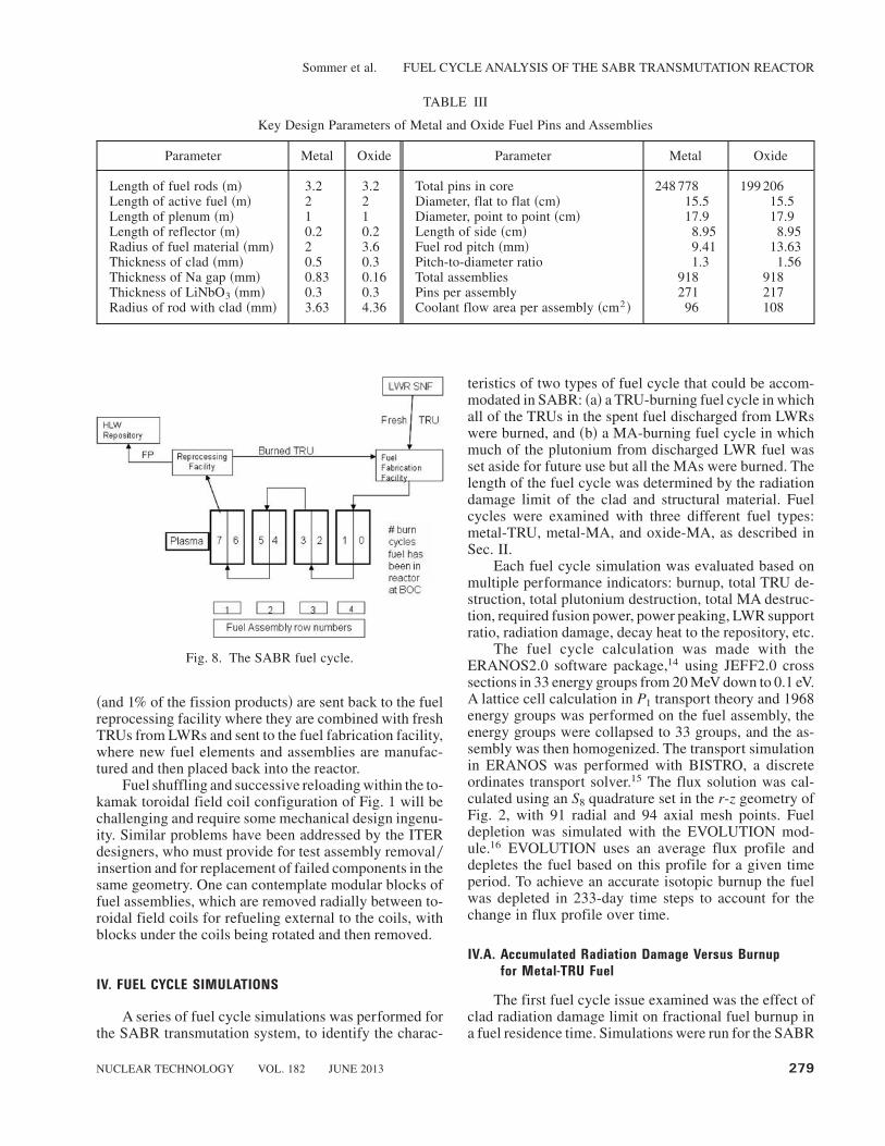
~and 1% of the fission products! are sent back to the fuelreprocessing facility where they are combined with freshTRUs from LWRs and sent to the fuel fabrication facility,where new fuel elements and assemblies are manufac-tured and then placed back into the reactor.
Fuel shuffling and successive reloading within the to-kamak toroidal field coil configuration of Fig. 1 will bechallenging and require some mechanical design ingenu-ity. Similar problems have been addressed by the ITERdesigners, who must provide for test assembly removal0insertion and for replacement of failed components in thesame geometry. One can contemplate modular blocks offuel assemblies, which are removed radially between to-roidal field coils for refueling external to the coils, withblocks under the coils being rotated and then removed.
IV. FUEL CYCLE SIMULATIONS
A series of fuel cycle simulations was performed forthe SABR transmutation system, to identify the charac-
teristics of two types of fuel cycle that could be accom-modated in SABR: ~a! a TRU-burning fuel cycle in whichall of the TRUs in the spent fuel discharged from LWRswere burned, and ~b! a MA-burning fuel cycle in whichmuch of the plutonium from discharged LWR fuel wasset aside for future use but all the MAs were burned. Thelength of the fuel cycle was determined by the radiationdamage limit of the clad and structural material. Fuelcycles were examined with three different fuel types:metal-TRU, metal-MA, and oxide-MA, as described inSec. II.
Each fuel cycle simulation was evaluated based onmultiple performance indicators: burnup, total TRU de-struction, total plutonium destruction, total MA destruc-tion, required fusion power, power peaking, LWR supportratio, radiation damage, decay heat to the repository, etc.
The fuel cycle calculation was made with theERANOS2.0 software package,14 using JEFF2.0 crosssections in 33 energy groups from 20 MeV down to 0.1 eV.A lattice cell calculation in P1 transport theory and 1968energy groups was performed on the fuel assembly, theenergy groups were collapsed to 33 groups, and the as-sembly was then homogenized. The transport simulationin ERANOS was performed with BISTRO, a discreteordinates transport solver.15 The flux solution was cal-culated using an S8 quadrature set in the r-z geometry ofFig. 2, with 91 radial and 94 axial mesh points. Fueldepletion was simulated with the EVOLUTION mod-ule.16 EVOLUTION uses an average flux profile anddepletes the fuel based on this profile for a given timeperiod. To achieve an accurate isotopic burnup the fuelwas depleted in 233-day time steps to account for thechange in flux profile over time.
IV.A. Accumulated Radiation Damage Versus Burnup
for Metal-TRU Fuel
The first fuel cycle issue examined was the effect ofclad radiation damage limit on fractional fuel burnup ina fuel residence time. Simulations were run for the SABR
TABLE III
Key Design Parameters of Metal and Oxide Fuel Pins and Assemblies
Parameter Metal Oxide Parameter Metal Oxide
Length of fuel rods ~m! 3.2 3.2 Total pins in core 248 778 199 206Length of active fuel ~m! 2 2 Diameter, flat to flat ~cm! 15.5 15.5Length of plenum ~m! 1 1 Diameter, point to point ~cm! 17.9 17.9Length of reflector ~m! 0.2 0.2 Length of side ~cm! 8.95 8.95Radius of fuel material ~mm! 2 3.6 Fuel rod pitch ~mm! 9.41 13.63Thickness of clad ~mm! 0.5 0.3 Pitch-to-diameter ratio 1.3 1.56Thickness of Na gap ~mm! 0.83 0.16 Total assemblies 918 918Thickness of LiNbO3 ~mm! 0.3 0.3 Pins per assembly 271 217Radius of rod with clad ~mm! 3.63 4.36 Coolant flow area per assembly ~cm2 ! 96 108
Fig. 8. The SABR fuel cycle.
Sommer et al. FUEL CYCLE ANALYSIS OF THE SABR TRANSMUTATION REACTOR
NUCLEAR TECHNOLOGY VOL. 182 JUNE 2013 279

out-to-in shuffling pattern for irradiation times corre-sponding to 100, 200, and 300 displacements per atom~dpa!, as well as for a hypothetical once-through fuelcycle with a radiation damage limit sufficient to achieve.90% burnup before the fuel is removed from the reac-tor. Radiation damage limits of 150 to 200 dpa are an-ticipated for clad and structural materials presently underdevelopment. The 300-dpa limit was investigated to de-termine if there is a strong incentive for developing newclad materials able to withstand a higher radiation dam-age dose. The once-through cycle was examined to de-termine what radiation damage limits would be needed toachieve high burnup of the TRU fuel without reprocess-ing and to examine the power distributions that wouldresult in such a low reactivity core.
The simulations show that the relationship betweenradiation damage and burnup is linear in the regime from100 to 300 dpa. This linear relationship results in linearincreases in fusion power and TRUs burned per resi-dence in this regime. The results are summarized inTable IV.
The TRU burnup rate depends on the fission rate, ofcourse, and the fission rate decreased as the fusion rateincreased to compensate for reactivity loss @recall that itis the total thermal power in the fission core that is heldconstant at 3000 MW~thermal!# . This accounts for thedownward trend in TRUs burned per year from the 100-dpa cycle to the once-through cycle. As can be seen fromTable IV, the ratio of fission power to fusion power in therecycling fuel cycles varies from.30 at BOL to;7.5 atthe end of the equilibrium fuel cycle ~EOC!.
Since a 1000-MW~electric! LWR produces ;250 kgof TRUs0yr, a support ratio of LWRs per SABR canbe defined by dividing the SABR TRU destruction rate
by the LWR production rate. For this purpose, we as-sume that SABR operates at 75% availability, takinginto account refueling downtime and unscheduleddowntime.
The assembly-average power peaking ~the assembly-average power in the first ring to the core-average powerover all four rings! indicated in Table IV is generally,2.0. The power is relatively uniform, with peak-to-average factors of 2 or less, except for the once-throughcycle where the very different composition of the fuel inadjacent rings produces large power peaking. The de-tailed power distribution is shown in Fig. 9 for EOC inthe most limiting 300-dpa case.
The distribution of accumulated fast-neutron~.100 keV! fluence and the dpa at the end of the 300-dpa equilibrium cycle are plotted in Figs. 10 and 11,respectively.
The jumps in the distributions occur between ringsof assemblies that have been in the reactor different num-bers of burn cycles. This sort of ring-to-ring power peak-ing can be handled by flow zoning among the rings ofassemblies,17 and the within-assembly dpa gradient canbe reduced by rotating the assemblies when they are shuf-fled between rings. No effort has been made yet to opti-mize the within-assembly power distribution.
The decay heat in the repository was calculated withORIGEN-S ~Ref. 18!. Fast-group cross sections wereimported into ORIGEN-S, and the fuel was then depletedunder a constant flux until the burnup reached the samelevel of burnup seen in ERANOS. The calculation ofdecay heat to the repository was done assuming repro-cessing separation efficiency of 1%, meaning 99% of thefission products and 1% of the TRUs go to the repositoryon each reprocessing step.
TABLE IV
Summary of Radiation Damage Versus Burnup
Parameter
Cycle 100 dpa 200 dpa 300 dpa Once throughBurn cycle length time ~days! 350 700 1000 4550Four-batch residence time ~yr! 3.83 7.67 10.95 49.8Fission power @MW~thermal!# 3000 3000 3000 3000FIMA ~%! 16.7 23.8 31.6 87.2
Region power peaking BOC0EOC 1.701.8 1.802.0 1.802.0 2.002.1BOL Pfus ~MW! 73 73 73 73BOC Pfus ~MW! 155 240 286 1012EOC Pfus ~MW! 218 370 461 1602BOL Keff 0.972 0.972 0.972 0.972BOC Keff 0.940 0.894 0.887 0.784EOC Keff 0.916 0.868 0.834 0.581
TRUs burned0yr ~kg! 1073 1064 909 545Support ratio ~75%! 2.9 3.2 3.6 2.2Clad damage ~dpa! 97 214 294 1537
Sommer et al. FUEL CYCLE ANALYSIS OF THE SABR TRANSMUTATION REACTOR
280 NUCLEAR TECHNOLOGY VOL. 182 JUNE 2013

Figure 12 shows the decay heat to the repository foreach of the four TRU burner fuel cycles, as well as forunprocessed fuel discharged after a typical LWR once-through fuel cycle. The decay heat to the repository is inproportion to the number of reprocessing steps, whichvaries inversely with the dpa limit. Clearly, a reduction inlong-time decay heat to the repository of more than afactor of 10 could be accomplished by recycling the TRUsin LWR spent fuel in SABR. While the decay heat isinversely proportional to the dpa limit, Fig. 12 indicatesthat a substantial factor of 10 reduction is achievablewith a radiation damage limit of 100 to 200 dpa, and it isnot critical to increase the dpa limit further in order tomake transmutation of TRUs realistic.
The initial calculations for fuel residence versus ra-diation damage were done assuming a fuel smear densityof 100% and no rotation of fuel assemblies with shuffling~i.e., the same face of the assembly would be locatedinboard as the assembly was shuffled from the outermostto the innermost ring over the fuel cycle!. The calcula-
tions on the reference 200-dpa cycle were repeated toinvestigate the effect of ~a! utilizing a smear density of95% to accommodate fuel swelling and expansion, andof ~b! rotating the fuel assemblies by 180 deg each timethey were shuffled. The results are summarized in Table V.
The effect of rotating the assemblies is minimal; theregional power peaking and the radiation damage arereduced by ;2% and 3%, respectively, while the rest ofthe parameters remain the same.
The effect of changing the fuel smear density ~a proxyfor the total heavy metal mass! has a significant impacton the fuel cycle. The major effect of lowered heavymetal mass is a reduction in multiplication constant k,with a corresponding increase in the required fusion powerPfus � const ~k0~1 � k!!Pfis. The decrease in heavy metalmass also reduces the amount of waste to the repositoryand the amount of decay heat to the repository both by;5%.
IV.B. Minor Actinide Burner
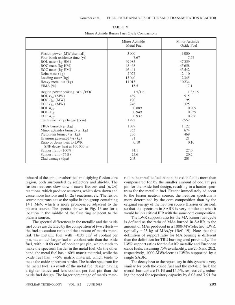
The MA burner fuel cycle analysis emphasizes fis-sioning the MAs in spent fuel while setting aside theplutonium for other uses, as specified in the Europeanstudies of reactors to burn MAs ~Ref. 7!. The same 200-dpa, four-batch-with-rotated-assembly fuel cycle de-scribed in Sec. III was analyzed for both the MA-oxideand the MA-metallic fuel burner fuel cycles ~see Table VI!.The fuel cycles were evaluated based on the same criteriaas used for the TRU burner fuel cycle.
The change in reactivity throughout the fuel cycle isgreater in the oxide fuel because more plutonium is burned.This requires a greater change in fusion power from be-ginning of cycle ~BOC! to EOC for the MA-oxide fuel.The fusion power required to maintain 3000-MW of
Fig. 9. Power distribution for the TRU burner fuel cycle at endof the 300-dpa equilibrium cycle.
Fig. 10. Fast-neutron fluence at end of the 300-dpa equilib-rium fuel cycle.
Fig. 11. Displacements per atom at end of the 300-dpa equi-librium fuel cycle.
Sommer et al. FUEL CYCLE ANALYSIS OF THE SABR TRANSMUTATION REACTOR
NUCLEAR TECHNOLOGY VOL. 182 JUNE 2013 281

thermal power in the core varied from Pfus � 200 to500 MW in these fuel cycles, and the rate of MA fission~destruction! was 850 and 675 kg per effective full-power year for the metal form and the oxide form of thefast reactor fuel, respectively.
The TRU transmutation rate for the MA fuel is1089 kg0yr for the metal fuel and 1122 kg0yr forthe oxide fuel. The metal fuel burns more MAs thanthe oxide fuel; 78.3% of the TRUs burned in the metal
fuel are MAs compared to 58.9% of the TRUs burnedin the oxide fuel. This is because the metal fuel is in aharder spectrum, making the fission cross section ofthe MAs more competitive with the fission cross sec-tion of the plutonium in the system. The normalizedflux spectra for the oxide fuel and the metal fuel areshown in Fig. 13.
The neutron transport calculation treats the fusionneutrons as a volume source in the plasma region just
Fig. 12. Decay heat to the repository.
TABLE V
Comparison of Rotated and Nonrotated 200-dpa Fuel Cycles with Metal Fuel
200 dpa Rotated~95% Densitya !
200 dpaNonrotated~95% Density!
200 dpaNonrotated~100% Density!
Fission power @MW~thermal!# 3 000 3 000 3 000BOL mass ~kg HM! 30 254 30 254 31 846FIMA ~%! 25.6 25.6 24.1
Region power peaking BOC0EOC 1.701.9 1.701.9 1.802.0BOL Pfus ~MW! 172 172 73BOC Pfus ~MW! 302 317 240EOC Pfus ~MW! 401 429 370BOL Keff 0.945 0.945 0.972BOC Keff 0.878 0.863 0.894EOC Keff 0.831 0.817 0.868Cycle reactivity change ~pcm! �6 441 �6 526 �3 351
TRUs burned0yr ~kg! 1 027 1 023 1 064Support ratio ~100%! 4.1 4.1 4.2Support ratio ~75%! 3.1 3.1 3.2Clad damage ~dpa! 212 218 214
aThe high values of the smear density are perhaps unrealistic, so the heavy metal mass is the relevant fuel parameter. The actualdesign ~pin and assembly! sizes would be somewhat different than the fuel design given in this paper in lower-smear-densitydesigns.
Sommer et al. FUEL CYCLE ANALYSIS OF THE SABR TRANSMUTATION REACTOR
282 NUCLEAR TECHNOLOGY VOL. 182 JUNE 2013
inboard of the annular subcritical multiplying fission coreregion, both surrounded by reflectors and shields. Thefusion neutrons slow down, cause fissions and ~n, 2n!reactions, which produce neutrons, which slow down andcause more fissions and ~n, 2n! reactions, etc. The fusionsource neutrons cause the spike in the group containing14.1 MeV, which is more pronounced adjacent to theplasma source. The spectra shown in Fig. 13 are for alocation in the middle of the first ring adjacent to theplasma source.
The spectral differences in the metallic and the oxidefuel cores are dictated by the competition of two effects—the fuel-to-coolant ratio and the amount of matrix mate-rial. The metallic fuel, with ;0.35 cm2 of coolant perpin, has a much larger fuel-to-coolant ratio than the oxidefuel, with ;0.69 cm2 of coolant per pin, which tends tomake the spectrum harder in the metal fuel. On the otherhand, the metal fuel has;60% matrix material, while theoxide fuel has ;45% matrix material, which tends tomake the oxide spectrum harder. The harder spectrum forthe metal fuel is a result of the metal fuel design havinga tighter lattice and less coolant per fuel pin than theoxide fuel design. The larger percentage of matrix mate-
rial in the metallic fuel than in the oxide fuel is more thancompensated for by the smaller amount of coolant perpin for the oxide fuel design, resulting in a harder spec-trum for the metallic fuel. Except immediately adjacentto the fusion neutron source, the neutron spectrum ismore determined by the core composition than by theoriginal energy of the neutron source ~fission or fusion!,so that the spectrum in SABR is very similar to what itwould be in a critical IFR with the same core composition.
The LWR support ratio for the MA burner fuel cycleis defined as the ratio of MAs burned in SABR to theamount of MAs produced in a 1000-MW~electric! LWR,typically ;25 kg of MAs0yr ~Ref. 19!. Note that thisdefinition of support ratio for MA burning is differentthan the definition for TRU burning used previously. TheLWR support ratios for the SABR metallic and Europeanoxide fuels, assuming 75% availability, are 25.6 and 20.2,respectively, 1000-MW~electric! LWRs supported by asingle SABR.
The decay heat to the repository in this system is verysimilar for both the oxide fuel and the metallic fuel; theoverall burnups are 17.1% and 15.5%, respectively, reduc-ing the need for repository capacity by 8.08 and 7.91 for
TABLE VI
Minor Actinide Burner Fuel Cycle Comparisons
Minor Actinide–Metal Fuel
Minor Actinide–Oxide Fuel
Fission power @MW~thermal!# 3 000 3 000Four-batch residence time ~yr! 7.67 7.67BOL mass ~kg HM! 49 985 47 359BOC mass ~kg HM! 48 468 45 658EOC mass ~kg HM! 46 441 43 542Delta mass ~kg! 2 027 2 110Loading outer ~kg! 13 040 12 345Heavy metal out ~kg! 11 013 10 234FIMA ~%! 15.5 17.1
Region power peaking BOC0EOC 1.501.6 1.301.5BOL Pfus ~MW! 489 515BOC Pfus ~MW! 190 195EOC Pfus ~MW! 246 325BOL Keff 0.889 0.909BOC Keff 0.949 0.959EOC Keff 0.932 0.936Cycle reactivity change ~pcm! �1 922 �2 552
TRUs burned0yr ~kg! 1 089 1 122Minor actinides burned0yr ~kg! 853 674Plutonium burned0yr ~kg! 236 469Uranium generated0yr ~kg! 31 21Ratio of decay heat to LWR
SNF decay heat at 100 000 yr0.10 0.10
Support ratio ~100%! 34.1 27.0Support ratio ~75%! 25.6 20.2Clad damage ~dpa! 203 201
Sommer et al. FUEL CYCLE ANALYSIS OF THE SABR TRANSMUTATION REACTOR
NUCLEAR TECHNOLOGY VOL. 182 JUNE 2013 283
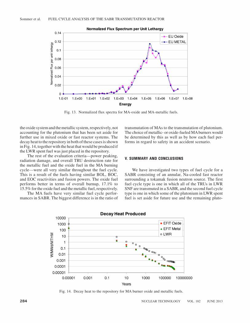
the oxide system and the metallic system, respectively, notaccounting for the plutonium that has been set aside forfurther use in mixed oxide or fast reactor systems. Thedecay heat to the repository in both of these cases is shownin Fig. 14, together with the heat that would be produced ifthe LWR spent fuel was just placed in the repository.
The rest of the evaluation criteria—power peaking,radiation damage, and overall TRU destruction rate forthe metallic fuel and the oxide fuel in the MA burningcycle—were all very similar throughout the fuel cycle.This is a result of the fuels having similar BOL, BOC,and EOC reactivities and fusion powers. The oxide fuelperforms better in terms of overall burnup, 17.1% to15.5% for the oxide fuel and the metallic fuel, respectively.
The MA fuels have very similar fuel cycle perfor-mances in SABR. The biggest difference is in the ratio of
transmutation of MAs to the transmutation of plutonium.The choice of metallic- or oxide-fueled MAburners wouldbe determined by this as well as by how each fuel per-forms in regard to safety in an accident scenario.
V. SUMMARY AND CONCLUSIONS
We have investigated two types of fuel cycle for aSABR consisting of an annular, Na-cooled fast reactorsurrounding a tokamak fusion neutron source. The firstfuel cycle type is one in which all of the TRUs in LWRSNF are transmuted in a SABR, and the second fuel cycletype is one in which some of the plutonium in LWR spentfuel is set aside for future use and the remaining pluto-
Fig. 13. Normalized flux spectra for MA-oxide and MA-metallic fuels.
Fig. 14. Decay heat to the repository for MA burner oxide and metallic fuels.
Sommer et al. FUEL CYCLE ANALYSIS OF THE SABR TRANSMUTATION REACTOR
284 NUCLEAR TECHNOLOGY VOL. 182 JUNE 2013

nium plus the MAs are transmuted in a SABR. In bothfuel cycle types, the fuel residence time between repro-cessing steps was set by radiation damage limits ~200 dpareference value!, and the separation of TRUs from fissionproducts was assumed to be only 99% efficient. We foundthat, by repeated recycling of the TRU fuel dischargedfrom SABR with a blend of fresh TRUs discharged fromLWRs, the decay heat of the repository content could bereduced by a factor of ;10 at 100 000 yr relative to thedecay heat if the discharged fuel from LWRs was burieddirectly. Noting that decay heat load was the limitingdesign factor for Yucca Mountain capacity, this reductionin decay heat implies a corresponding reduction by afactor of 10 in HLWR capacity requirement. This resultis based on the conservative assumption that the actinide–fission product separation efficiency is only 99%. Wenote that there are other measures ~e.g., Sr and Cs man-agement and cooling before storage! for reducing therequired repository capacity, and they are not incompat-ible with the transmutation solution proposed in this paper.
A 3000-MW~thermal! SABR operating on such fuelcycles, with 75% availability, would be capable of burn-ing all of the TRUs discharged annually from 3 LWRs of1000 MW~electric!, or burning all of the MAs and someof the plutonium discharged from 20 to 25 LWRs of 1000MW~electric!. Thus, one could envision a nuclear fleetwith 75% of the energy produced by LWRs and 25% ofthe energy produced by SABRs that burned all of theTRUs discharged from the LWRs.Alternatively, one couldenvision a nuclear fleet with 95% of the energy producedby LWRs and 5% produced by SABRs that burned theMAs ~primarily! and some of the plutonium dischargedfrom LWRs, while plutonium was accumulated to startup fast reactors.
REFERENCES
1. “Waste Management Background,” Office of Civilian Ra-dioactive Waste Management: http:00www.ocrwm.gov ~cur-rent as of July 9, 2012!.
2. “Expected New Reactor Applications,” Nuclear Regula-tory Commission: http:00www.nrc.gov0reactors0new-reactors0new-licensing-files0expected-new-rx-applications.pdf ~currentas of July 9, 2012!.
3. Proc. Int. Information Exchange Mtg. Actinide and Fis-sion Product Partitioning and Transmutation, mtgs. 1 through10, Organisation for Economic Co-operation and Develop-ment, Nuclear Energy Agency ~1990–2008!.
4. E. A. HOFFMAN and W. M. STACEY, “Comparative FuelCycle Analysis of Critical and Subcritical Fast Reactor Trans-mutation Systems,” Nucl. Technol., 144, 83 ~2003!.
5. C. M. SOMMER, W. M. STACEY, and B. PETROVIC,“Fuel Cycle Analysis of the SABR Subcritical TransmutationReactor Concept,” Nucl. Technol., 172, 48 ~2010!.
6. W. M. STACEY et al., “SABR Fusion-Fission Hybrid FastBurner Reactor Based on ITER,” presented at 11th InformationExchange Mtg. Actinide and Fission Product Partitioning andTransmutation, San Francisco, California, November 1–4, 2010,Nuclear Energy Agency.
7. V. ROMANELLO et al., “Advanced Fuel Cycle ScenarioStudy in the European Context by Using the SABR HybridFusion-Fission System,” presented at 11th Information Ex-change Mtg. Actinide and Fission Product Partitioning andTransmutation, San Francisco, California, November 1–4, 2010,Nuclear Energy Agency.
8. C. ARTIOLI et al., “Minor Actinide Transmutation in ADS:The EFIT Core Design,” presented at Int. Conf. Physics ofReactors, Interlaken, Switzerland, September 14–19, 2008.
9. W. M. STACEY et al., “A TRU-Zr Metal-Fuel, Sodium-Cooled Fast Subcritical Advanced Burner Reactor,” Nucl. Tech-nol., 162, 53 ~2008!.
10. N. HOLTKAMP, “The Status of the ITER Design,” FusionEng. Des., 84, 98 ~2009!.
11. C. E. TILL, Y. I. CHANG, and W. H. HANNUM, “TheIntegral Fast Reactor—An Overview,” Prog. Nucl. Energy, 31,1 ~1997!.
12. S. HAYES and M. MEYER, Argonne National Labora-tory, Personal Communication ~2007!.
13. J.-P. FLOYD et al., “Tokamak Fusion Neutron Source fora Fast Transmutation Reactor,” Fusion Sci. Technol., 52, 727~2007!.
14. G. RIMPAULT et al., “The ERANOS Code and Data Sys-tem for Fast Reactor Neutronic Analyses,” Proc. Int. Conf.New Frontiers of Nuclear Technology: Reactor Physics, Safetyand High-Performance Computing ~PHYSOR 2002!, Seoul,South Korea, October 7–10, 2002, American Nuclear Society~2002!.
15. C. GHO and G. PALMIOTTI, “BISTRO: Bidimensionnelsn transport optimize, un programme bidimensionnel de trans-port sn aux differences finies note n1 definision des algorithmspour la geometrie x-y,” technical report.
16. J. Y. DORIATH et al., “Eranos Manuel Des Methodes—Les Calculs D’Evolution,” CEA.
17. A. BOPP, Georgia Institute of Technology, Personal Com-munication ~2011!.
18. “SCALE: A Modular Code System for Performing Stan-dardized ComputerAnalyses for Licensing Evaluation,” ORNL0TM-2005039, Version 5.1, Oak Ridge National Laboratory.
19. F. GOLDNER and R. VERSLUIS, “Transmutation Capa-bilities of GEN-IVReactors,” September 2006; http:00www.nea.fr0html0pt0iempt90Nimes_Presentations0GOLDNER4.pdf~current as of July 9, 2012!.
Sommer et al. FUEL CYCLE ANALYSIS OF THE SABR TRANSMUTATION REACTOR
NUCLEAR TECHNOLOGY VOL. 182 JUNE 2013 285