Complex Dynamical Behavior of a Two-Stage Colpitts Oscillator with ...

Transmitters
Electron Pumpsthat convert
DC Power intoAC Power


An Early Amateur Spark Gap TransmitterCombine High Voltage and Exposed Wiring,What Could Possibly Go Wrong?


Collins Gear mid shelf, Modern Elecraft on the bottom shelf,And Station Accessories on the top shelf.

Resonant SystemsA child’s swing is a resonant system.When energy is put into the mass bya push the mass will swing back andforth at a constant rate, a frequencyof swings per unit of time. Theamplitude will decrease over timebecause of friction .
A constant amplitude of swingrequires a well timed push
An Oscillator combines a Resonant Circuit to set the Frequencywith an Amplifier to provide the energy to continue the oscillation.

Heinrich Barkhausen (1881-1956) said in 1921:“For a positive feedback system, oscillation will occur when theloop gain (the product of forward gain and feedback gain) has aphase shift of zero and a magnitude of unity.”
“Amplifiers oscillate and oscillators amplify”Whenever the positive feedback gain of the entire system isequal to or greater than one, the circuit will oscillate.
Oscillator
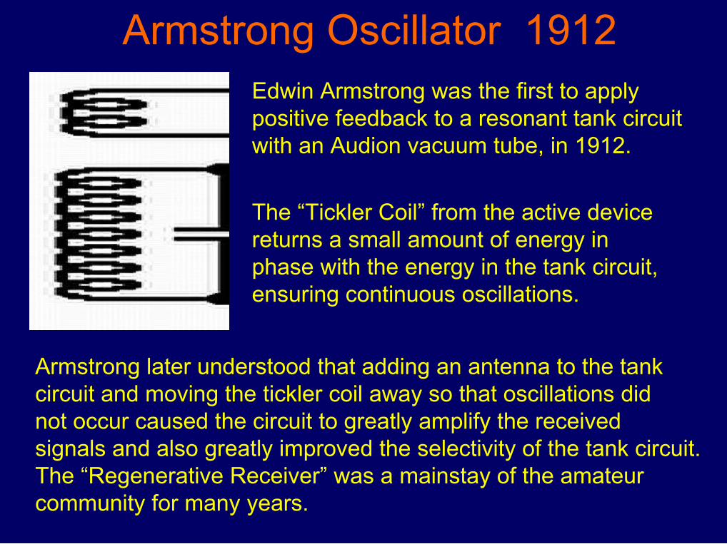
Armstrong Oscillator 1912Edwin Armstrong was the first to applypositive feedback to a resonant tank circuitwith an Audion vacuum tube, in 1912.
The “Tickler Coil” from the active devicereturns a small amount of energy inphase with the energy in the tank circuit,ensuring continuous oscillations.
Armstrong later understood that adding an antenna to the tankcircuit and moving the tickler coil away so that oscillations didnot occur caused the circuit to greatly amplify the receivedsignals and also greatly improved the selectivity of the tank circuit.The “Regenerative Receiver” was a mainstay of the amateurcommunity for many years.

This schematic of anArmstrong Transmitter datesfrom the early 1920s.
The Exciter Tube creates the oscillation with C and L1+L2.
The Power Tube creates atime varying current in thecoil Lp, which magneticallycouples to the antenna coil,creating an alternating currentin the antenna wire.
An alternating current in a wirecreates electromagnetic waveswhich radiate away from theantenna. RADIO !

Desirable Oscillator Characteristics
Frequency Stability:
Frequency should stay constant for long periods of time. Frequency Drift is measured in Hz of drift per hour.
Changes in temperature or supply voltage will change the frequency.

Pierce Quartz Crystal Oscillator 1923In 1923 W.G. Cody demonstrated toG.W. Pierce the frequency stabilityof a quartz disk oscillator. Piercethen designed a vacuum tube circuitthat maintained oscillation.
“Rock Stable”The Crystal operates in Seriesresonant mode, creating a 180o phaseshift between the Drain and the Gate.
The 2-27pF trimmer cap provides some adjustment for thecrystal frequency. The Pierce oscillator is probably the mostreliable of the simple oscillators for simple transmitter use.

Quartz: Silicon DioxidePiezoelectric: Electrical field bends the crystal structure.
Dimensionally exceptionally stable with temperature, so acrystal does not change size. Resonant frequency depends uponsize, both disk diameter and thickness.
Many Standard Frequency Crystals and whole Oscillators are “onthe shelf” available, and custom Frequencies can be ordered witha two week delivery for reasonable cost.

Spectrum Scan of a Continuous Wave Signal.The Carrier is of Constant Amplitude and SingleFrequency. The only information conveyed is“I Am Here.”

ModulationChanging the Radio Signal to convey Information
A Radio Signal, or “Carrier”, may be changed in three ways, by Amplitude, by Frequency, and by Phase. Some modulation schemes use all three methods at the same time.
The most basic modulation method is to turn the carrier on and off, letting the pattern of on periods carry meaning, such as with Morse Code, or “CW”.
CW is short form for Continuous Wave, and refers to the unmodulated carrier emitted by the keyed transmitter.

The first fully digital mode, invented by Alfred Vail, was coded with dots, spaces and dashes. A radio frequency carrier is switched on with each press on a key, also by Vail.


A CW Transmitter - Simplified
The Carrier Oscillator creates the radio frequency alternating current signal at the desired frequency.
The keyed driver/buffer amplifies the RF signal when the key is closed. This amplifier also shields the oscillator from changes in the Power Amplifier which may shift the RF frequency.
The Power Amplifier develops the RF energy which is then coupled to the antenna for radiation. This stage may be keyed, or a class C amplifier which draws DC current only when driven.

A Colpitts Crystal Oscillator generates a continuous carrier signal.
The Keyed RF Amplifier only amplifies when the key is closed andDC current flows, sending dots or dashes in Morse Code.
The Final RF amplifier is turned on by the keyed RF and drivesa parallel resonant tank circuit which is link coupled to an antenna.
Simple QRP CW Transmitter

Class C RF Output Stage
RFC
Many CW and FM Transmitters use a Class C output for Power
An RF Choke applies B+ to the Transistor Collector
The Transistor is driven completely on by the input signal
An Impedance Matching Low Pass Filter converts the Collector pulses to a fair approximation of a pure sine wave
The Collector Impedance is very low, just an ohm or two, so lots of current flows. A typical Antenna Load is 50.

Modern Receivers incorporate a Band Scan and Waterfalldisplay which shows all the signals in a set bandwidth.
This is a small portion of the 40m CW Band.
W
JUSTRE

Captured during a CW Contest last weekend. Each division is 1kHzand you can see some CW signals are very wide, as much as600 Hz. This is due to high keying speed, and over driving the transmitter with a computer generated audio signal.
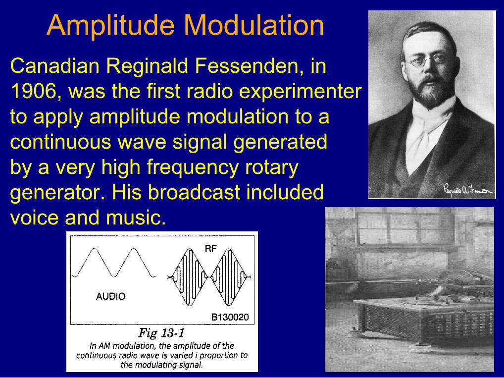
Amplitude ModulationCanadian Reginald Fessenden, in1906, was the first radio experimenterto apply amplitude modulation to acontinuous wave signal generatedby a very high frequency rotarygenerator. His broadcast includedvoice and music.

A Simplified Amplitude Modulated Transmitter
A VFO allows a change in transmitfrequency, butgetting stability is very hard.
A Frequency Multiplier generates harmonics of the VFO frequency and then amplifies one of them. Almost never used with a VFO because it would worsen VFO drift.
The Microphone-Speech Amplifier-Modulator is basically a very powerful PA system, generating as much audio power as the RF Power Amplifier makes in RF.Unlike your home HiFi, the audio frequency response is limited to 200Hz to 3000Hz, as this is where the speech intelligence is most effective for communications grade audio.


Peak Power

Spectrum Scan of a carrier (central peak) amplitude modulatedby a single tone. Two Sidebands are created, lower than the carrier by the frequency of the audio tone, and higher than the carrier by the frequency of the modulating tone.
The Radio Carrier does not change in amplitude with AM.

The Upper and Lower Sidebands carry all the information, tones or vocal audio. Each sideband contains 25% of the carrier power at 100% modulation. Thus a 1kW AM transmitter will put out a maximum of 1.5kW on modulation peaks.
The Carrier serves as a frequency reference and allows for accurate demodulation of the sidebands with simple diode detectors.
AM Broadcasters are allowed to positively modulate to 135%, but must not negitively modulate beyond 100%, or they go off the air!

Some foreign Shortwave Broadcasters transmit within the40m Ham Band. This AM transmission on 7210kHz showsthe central carrier and identical sidebands +&- 12kHz.

This fine example of an AmateurHomebrew Amplitude Modulated1kW Transmitter is designed asModules which are rack mounted.
The exciter is crystal controlled, sooperation is on a single favouritefrequency.
Change the crystal to QSY.
Windows allow the operator toaccess power tube performance.
The Audio Modulation tubes areseen in the bottom window, whilethe Radio Frequency Power tubesare seen in the top windows.
All power tubes are Eimac 3-500Z.

An Amateur Station pre 1970

The Problem With Harmonics
Most transmitter power output stages create Harmonics of the fundamental signal. A Harmonic is a multiple of the fundamental frequency. Most problematic are the 3rd and 5th.
Harmonic outputs can interfere with other spectrum users.For Example: On the 15m band the third harmonic of 21MHz is 63MHz, right in the TV Channel 3 allocation.
Modern power output stages include special low pass filters that pass the desired band and suppress higher frequencies to remove the harmonic energy.
Homebrew and older transmitters relied upon external filters.
Fc
2nd3rd
4th5th
6th 7th

Low Pass Filter
Passes all frequenciesbelow 30MHz, Cutsoff everything in theTV and FM band.Prevents AmateurTransmissions frominterfering with TV Broadcast reception.

Standing Wave Ratio Meter

SWR Pickups
Brune Bridge has good frequency range, and linear power response,but must be trimmed for directionality and high frequencycompensation. Easy to build andadjust for high accuracy.
Line Sampler Not very sensitive at low frequency.
Tandem Bridge Good frequencyrange and linear power response.

Commercial Antenna Tuners

VE3GSO SWR/Power Meter, C-L-C Antenna Tuner, Antenna Switch


Antenna Reactance, either Inductive or Capacitive,does not Dissipate Power, but Returns Powerto the Source.
Forward Power
Reflected Power
The Antenna Tuner creates a Conjugate Matchfor the Reflected Power so it is returned to theAntenna along with the Forward Power.
The Transmitter sees a perfect load match andno Reflected Power. Maximum Power is achieved!
TransmitPower 100W
25W
125W100W

Dummy LoadA 50 non-inductive resistorhoused in a well shielded containerto prevent radiation.
Used for transmitter tune upand testing. The resistor may bebathed in oil to increase heatdissipation.
A simple 50 load can bemade with 20 of 1000 2Wcarbon resistors in parallel.
A large oil bath will triple thePower dissipation.

A Modern Amateur Station Layout

A Pre-WARC 100W Solid State Transceiver
In the late 70's this rig was a marvel of miniaturization. It was reasonably stable after anhour of warmup, delivered 100W output, and was within a modest budget.
Notice that the digital readout does not agree with the mechanical dial, a common faultthat drove some owners quite mad.

LARC Club Station VE3LONIcom IC-718 & LDG IT-100 Auto Tuner


Amplitude Modulation Creates two Identical Sidebands
Each Sideband contains the same information.
The Carrier is at Full Power, serving only to demodulatethe sidebands in simple AM diode detectors.
For Hams this is a waste of Precious Transmitter Power

A Balanced Mixer creates both Sidebands, Upper and Lower.
The Carrier is Suppressed by Phase Cancellation.
This Double Sideband, Suppressed Carrier Signal could betransmitted as is, with each sideband serving as a back upif Selective Fading is a problem in the communications link.

A Selective Filter of 2.7kHz Bandwidth removes one ofthe Sidebands, resulting in a Single Sideband SuppressedCarrier Signal, (SSBSC or SSB) which makes maximumuse of the Transmitter Amplifier Power Available.

Single Sideband Suppressed Carrier GenerationSideband Filter Method
A Carrier signal is modulated in a balanced mixer to create a double sidebandsuppressed carrier signal.
A narrow band filter, 2.7kHz, passes one sideband and blocks the opposite sideband.
This Single Sideband Signal is then mixed with a second oscillator to thedesired RF band.
A 9MHz Carrier creates USB and when mixed with a 5MHz B.O. sums to create USBon 14MHz OR if subtracted creates LSB on 4MHz.

Single Sideband Suppressed Carrier GenerationSideband Filter Method
The RF amplifiers used to increase SSB power levels must be highly Linear, which means signals are not distorted in any way.
Class A or AB2 amplifiers are used, which are less efficient than
Class C, but do not distort the SSB signal.

Single Sideband Suppressed Carrier Generation
Phasing Method
Carrier and Audio are mixed in a balanced mixer to create In Phase DSBSC.
90o Phase Shifted Carrier and Audio are mixed in a balanced mixer tocreate Quadrature Double Sideband Suppressed Carrier.
When I and Q are summed a Upper Sideband Signal is generated.
When I and Q are subtracted a Lower Sideband Signal is generated.
The SSB signal is then mixed to the final transmit frequency.

Amplifier Operating Classes
Only Class A amplifiers reproduce the entire waveform cycle with little distortion. The price they pay is poor Power Efficiency, which means lots of waste heat in the amplifier.SSB amplifiers must be Linear, amplifying without distortion. Usually Class AB is used.

A Strong and a Weak SSB signal

Time for a 5 minute break
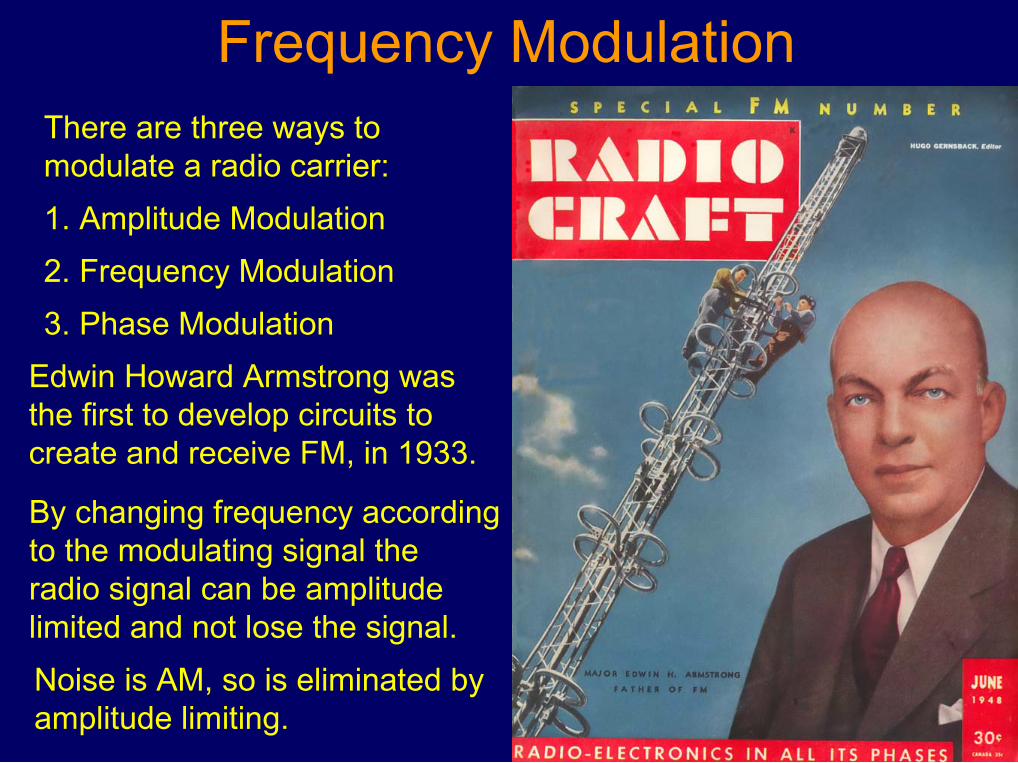
Frequency ModulationThere are three ways tomodulate a radio carrier:
1. Amplitude Modulation
2. Frequency Modulation
3. Phase Modulation
Edwin Howard Armstrong wasthe first to develop circuits tocreate and receive FM, in 1933.
By changing frequency accordingto the modulating signal theradio signal can be amplitudelimited and not lose the signal.
Noise is AM, so is eliminated byamplitude limiting.


The FM Waveform
The FM Radio Signal changes Frequency in accordance to themodulation signal amplitude.
A high signal voltage creates a high frequency deviation, while a low voltage creates a small frequency deviation.
A high audio frequency modulating signal creates a high rate of change of frequency, while a low audio frequency modulating signal changes the frequency slowly.
The amplitude or power of the FM signal does not change.


The Microphone converts Acoustic Signals into Electrical Signals.
The Speech Amplifier increases the audio signal while limiting the frequencies to 300Hz to 3000Hz. Pre-emphasis is also applied to increase higher frequencies and decrease low frequencies.
The Modulator changes the frequency of the RF Oscillator in accordance with the strength of the audio signal.
The Oscillator Frequency may be Frequency Multiplied to bring the FM signal up to the Transmit Frequency. 2X, 3X, 4X, 6X are used.
The Power Amplifier increases the FM signal to the power required for the communication application.

The FM Transmitter
Audio for FM is frequency limited and amplitude limited to limit thebandwidth of the FM sidebands to the specified radio channel.
Audio for FM is pre-emphasised to increase the strength of thehigh frequencies so that in the receiver the audio can bede-emphasised to reduce high frequency noise.
Amplification of the Frequency Modulated Carrier may be done inhigh efficiency Class C amplifiers and frequency multipliers.
Power Amplifiers are also Class C for high efficiency.

Terms Definition
Deviation: The amount of frequency shift of the radio carrier toeither side of the Centre Frequency. eg: +&- 5kHz
Centre Frequency: The carrier frequency of the transmitter withoutany modulating audio. eg: 147.06 MHz
Modulation Index: The ratio of the Carrier Deviation to theFrequency of the Modulating Signal.
M.I. = Deviation / Modulating Frequency
Deviation Ratio: Peak Deviation / Highest Modulating Frequency
eg: 5kHz / 3kHz = 1.666
FM noise suppression improves with higher Deviation Ratio.

Frequency Modulated Sidebands
As the full strength radio carrier deviates in frequency it depositspower across a wide band of frequencies, in direct accordancewith the modulating signal amplitude and frequency.A FM Radio Carrier is much wider than a similar AM signal, butnoise immunity and higher fidelity is worth it. FM radio is bestsuited to higher frequency bands where bandwidth is available.
At a Modulation Index of 2.4 the carrier disappears with alltransmitter power contained in the sidebands. A Bissell Null.

At some Modulating frequency and deviation, all the carrierpower is in the sidebands and the carrier frequency is empty.
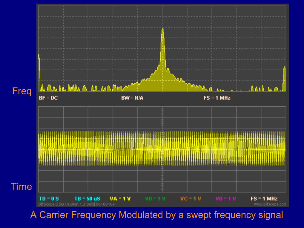
Freq
Time
A Carrier Frequency Modulated by a swept frequency signal

Phase Modulation
A Sine Wave can be thought of as a Vector Rotating Counter-Clockwise, with one full rotation in one Cycle.
The Length of the Vector represents the amplitude of the signal.The Number of full rotations in one second is the Frequency.The position in Degrees away from the 0 position at any momentis the phase of the signal at that moment.

PSK - Phase Shift Keying
BPSK - Binary Phase Shift Keying
QPSK - Quadrature Phase Shift Keying
O-QPSK - Offset Quadrature Phase Shift Keying
8 PSK - 8 Point Phase Shift Keying
16 PSK - 16 Point Phase Shift Keying
QAM - Quadrature Amplitude Modulation
16 QAM - 16 Point Quadrature Amplitude Modulation
64 QAM - 64 Point Quadrature Amplitude Modulation
256 QAM - 256 Point Quadrature Amplitude Modulation
MSK - Minimum Shift Keying
GMSK - Gaussian filtered Minimum Shift Keying
Multiple PSK Modulation Schemes

Binary Phase Shift Keying
This 180o Phase Shift encodes a change of state from a 0 to 1 ora 1 to 0. The phase shift occurs at the zero crossover.
PSK-31 uses a phase shift at 31 symbols per second to providereliable communications at low power.
Phase Modulation
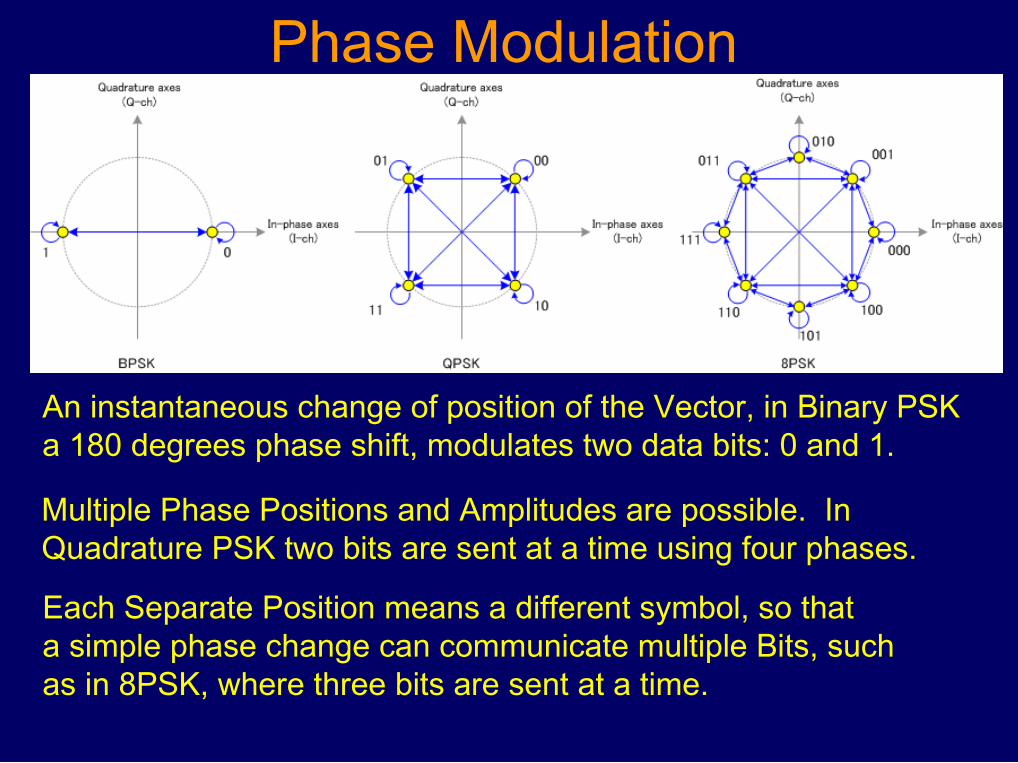
An instantaneous change of position of the Vector, in Binary PSKa 180 degrees phase shift, modulates two data bits: 0 and 1.
Multiple Phase Positions and Amplitudes are possible. InQuadrature PSK two bits are sent at a time using four phases.
Each Separate Position means a different symbol, so thata simple phase change can communicate multiple Bits, suchas in 8PSK, where three bits are sent at a time.

Modern Digital Communication Modes
Amateur Radio is fortunate to have many knowledgeable and generous members who utilize their skills to create Software that is freely available to everyone for the Digital Mode of choice.
A USB connected MODEM (Modulator-Demodulator) creates the Audio Tones that encode the computer data for transmission by any SSB transceiver.
Olivia, PSK31, PSK63, Pactor, FT-8, RTTY, WSPR, SSTV, MFSK,Throb, Hellschreiber, Field Hell, DV, Packet, Contesta, JT65M, Thor, Domino, MT63, HamDRM, Digital SSTV, etc.
www.hfradio.org.uk/html/digital_modes.html

PSK31 is a digital communications mode ideal for livekeyboard-to-keyboard conversations, similar to radioteletype.
Concept proposed by Pawel, SP9VRC and developedcompletely by Peter Martinez, G3PLX
Data rate is 31.25 bauds (about 50 word-per-minute),with narrow bandwidth (approximately 60 Hz at -26 dB)reduces its susceptibility to noise, and ideal for QRP.
It uses BPSK modulation without error correction orQPSK modulation with error correction:
PSK31


FT-8 Frankie Taylor 8 Tones

JT65-HF Dr. Joe Taylor