
Transmitted Power Formulation for the Implementation of ...
23
© 2005, it - instituto de telecomunicações. Todos os direitos reservados. Jessica Acevedo Flores Daniel Robalo Fernando J. Velez Transmitted Power Formulation for the Implementation of Spectrum Aggregation in LTE-Advanced over 800 MHz and 2 GHz Frequency Bands 7º Congresso Comité Portugués da URSI 22 de novembro de 2013 / Lisboa, Portugal
Transcript of Transmitted Power Formulation for the Implementation of ...

© 2005, it - instituto de telecomunicações. Todos os direitos reservados.
Jessica Acevedo Flores
Daniel Robalo
Fernando J. Velez
Transmitted Power Formulation
for the Implementation of
Spectrum Aggregation in
LTE-Advanced over 800 MHz and
2 GHz Frequency Bands
7º Congresso Comité Portugués da URSI
22 de novembro de 2013 / Lisboa, Portugal
2 22 de novembro de 2013 / Lisboa, Portugal
Outline
Introduction;
Objectives;
System model;
Topology;
Average SINR;
Normalized Transmitter Power;
Simulation results;
Conclusions and Future Work.
7º Congresso Comité Portugués da URSI

3
Introduction
Dynamic Spectrum Access (DSA) comprises Spectrum Aggregation
(SA) to alleviate the spectrum scarcity problem;
Radio Resource Management (RRM) guarantees Quality of Service
(QoS), since scheduling determines among packets that are ready for
transmission;
Common RRM (CRRM) ensures an efficient and coordinated use of
the available radio resources in heterogeneous networks scenarios.
22 de novembro de 2013 / Lisboa, Portugal
7º Congresso Comité Portugués da URSI
DL
DL
Operator 1
DL band
Operator 2
DL band
Operator 3
DL band
Shared by all 3
operators
DL
DL
4
Objectives
To propose a formulation to calculate the transmitter power required
to cover cells of different sizes whilst maintaining the average
Signal-to-Interference-plus-Noise Ratio (SINR) constant;
To consider a MultiBand-CRRM entity, for the 2 GHz and 800 MHz
frequency bands for a single operator scenario under a constant
average SINR using the LTE Simulator in [1];
To implement the integrated-CRRM [2], where CRRM and SA
functionalities are handled simultaneously, in order to facilitate the
best user allocation and maximize the total network throughput in
LTE systems.
[1] G. Piro, L. A. Grieco, G. Boggia, F. Capozzi and P. Camarda, “Simulating LTE Cellular Systems:
an Open Source Framework,” IEEE Transaction on Vehicular Technologies, Vol. 60, No. 2, Feb 2011,
pp. 498-513.
[2] O. Cabral, F. Meucci, A. Mihovska, F.J. Velez and N.R. Prasad. Integrated Common Radio
Resource Management with Spectrum Aggregation over Non-Contiguous Frequency Bands. Wireless
Personal Communications, Vol. 59, No. 3, Aug. 2011, pp. 499-523.
22 de novembro de 2013 / Lisboa, Portugal
7º Congresso Comité Portugués da URSI

5
System Model
Carrier frequency 800 MHz 2 GHz
Bandwidth, BW 5 MHz 5 MHz
Path loss model
Path Loss Model
The radio channel follows the ITU radio propagation COST-231 Hata
model for urban and suburban scenarios ;
R is the base station (BS)/user equipment (UE) maximum separation,
f is the carrier frequency, and Dhb is the BS antenna height (from the
average rooftop level).
Considering two carrier frequencies, 800 MHz and 2 GHz, Dhb = 15 m
and a UE antenna of 1.5 m, we obtain the following path loss model:
)(log)1041(40 ][10][3
][ KmKmhbdB RDL 80)(log21)(log18 ][10][10 MHzKmhb fD
22 de novembro de 2013 / Lisboa, Portugal
7º Congresso Comité Portugués da URSI

6
Parameters for LTE DL budget for a data rate of 1 Mbps and a commercial
omnidirectional antenna.
System Model (II)
Transmitter – NodeB
a) Max. TX power (dBm) 50
b) TX antenna gain (dBi) 3 - 3.5 For 800 MHz and 2 GHz respectively
c) Body loss (dB) 2
d) EIRP (dBm) 51- 51.5 = a + b – c
Receiver UE
e) Node B noise figure (dB) 8 LTE specifications
f) Receiver noise floor (dBm) -99 =-174+10log (BW) + e
g) SINR (dB) -10 From simulations
h) Receiver sensitivity (dBm) -109 = f + g
i) Interference margin (dB) 3
j) Cable loss (dB) 1
k) RX antenna gain (dBi) 0
l) Fast fade margin (dB) 0
m) Maximum path loss (dBm) 156-156.5 = d – h – i – j + k – l
22 de novembro de 2013 / Lisboa, Portugal
7º Congresso Comité Portugués da URSI

7
Topology
Hexagonal cell
deployment, with
frequency reuse
factor K = 3;
In co-channel
interference.
22 de novembro de 2013 / Lisboa, Portugal
7º Congresso Comité Portugués da URSI

8
Topology (II)
where:
PTx is BS transmitter power;
Pow is the power received from the own
cell;
α is the orthogonality factor;
Pnh is the total amount of interfering power
coming from the neighbour cells;
is the thermal noise power, given by:
being NF = 8 dB for LTE and BW = 5 MHz.
SINR
22 de novembro de 2013 / Lisboa, Portugal
7º Congresso Comité Portugués da URSI

9
with,
=
,,
=
,
=
where
are the antenna gains
PTx = 1 dB;
= 3 dBi;
= 3.5 dBi;
= 0 dBi.
Topology (III)
Received power and Interference
22 de novembro de 2013 / Lisboa, Portugal
7º Congresso Comité Portugués da URSI

10
Topology (IV)
PL, at 800 MHz:
PL, at 2 GHz:
Path loss
22 de novembro de 2013 / Lisboa, Portugal
7º Congresso Comité Portugués da URSI
11
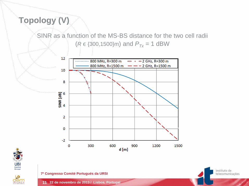
Topology (V)
SINR as a function of the MS-BS distance for the two cell radii
(R ϵ {300,1500}m) and PTx = 1 dBW
22 de novembro de 2013 / Lisboa, Portugal
7º Congresso Comité Portugués da URSI

12
Average SINR
where
= 6·
Acellnh is the total affected
cell area;
Acellnh=
is the total
integration area to calculate
(neighbour) cell
interference.
22 de novembro de 2013 / Lisboa, Portugal
7º Congresso Comité Portugués da URSI

13
Average SINR: Power and interference (II)
where
=
is the total integration area to compute the
signal/power and own cell interference;
is the Fraunhofer distance and is different for each frequency band,
depending on antenna specifications.
cellr
ryx
A
xy
RxTxTxTxMHzow GGPyxPP10
log2.376.119
800
2210
3
1
,
10),,(
nhcellr
ryx
A
xy
RxTxTxTxMHznh GGPyxPP10
log2.376.119
800
2210
3
1
,
10),,(
cellr
ryx
A
xy
RxTxTxTxGHzow GGPyxPP10
log37.6+128.1
2
2210
3
1
,
10),,(
nhcellr
ryx
A
xy
RxTxTxTxGHznh GGPyxPP10
log37.6+128.1
2
2210
3
1
,
10),,(
22 de novembro de 2013 / Lisboa, Portugal
7º Congresso Comité Portugués da URSI

14
Average SINR (III)
Average power and interference within a cell as a function of the
inter-cell distance with PTx = 1 dBW and α = 1.
22 de novembro de 2013 / Lisboa, Portugal
7º Congresso Comité Portugués da URSI

15
Average SINR (IV)
Average SINR as a function of the cell radius with different
orthogonality values (α ϵ {0.9, 1}) and constant PTx = 1 dBW for
the 800 MHz and 2 GHz frequency bands.
22 de novembro de 2013 / Lisboa, Portugal
7º Congresso Comité Portugués da URSI
16
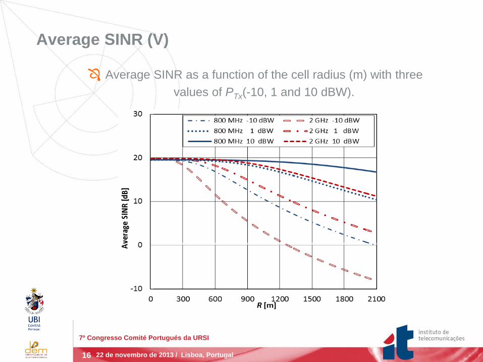
Average SINR (V)
Average SINR as a function of the cell radius (m) with three
values of PTx(-10, 1 and 10 dBW).
22 de novembro de 2013 / Lisboa, Portugal
7º Congresso Comité Portugués da URSI

17
Normalized Transmitter Power
Normalized PTx required to achieve a selected high average SINR (dB),
near the maximum, as a function of the cell radius at 800 MHz and 2 GHz.
22 de novembro de 2013 / Lisboa, Portugal
7º Congresso Comité Portugués da URSI

18
Video Traffic Throughput
Video traffic simulation setup:
Traced-based video sessions have been addressed for
simulations, these applications send packets based on realistic
video trace files;
We have considered a video bit rate of 128 kbps;
Modified Largest Weighted Delay First (MLWDF) scheduler.
22 de novembro de 2013 / Lisboa, Portugal
7º Congresso Comité Portugués da URSI

19
Results for video Traffic Throughput
Average Throughput vs. number of users for different cell radii
22 de novembro de 2013 / Lisboa, Portugal
7º Congresso Comité Portugués da URSI

20
Results for video Traffic Throughput (II)
Average Throughput as a function of cell radius, R, for 40 users (2 GHz
and 800 MHz bands) and 2X40 users with CRRM
22 de novembro de 2013 / Lisboa, Portugal
7º Congresso Comité Portugués da URSI

21
We propose an innovative formulation to calculate the transmitter
power required to cover cells of different sizes whilst maintaining
the average SINR constant, in the context of SA and MB-scheduler
to switch the users between two frequency bands -800 MHz and 2
GHz- for LTE systems;
We considered a topology with K = 3 and the COST-231 Hata
model for the path loss, and obtained the average SINR in the cell;
To assess the possible impact of non-ideal orthogonalities,
(α = 0.9), we have also evaluated the impact of the DL
orthogonality factor in the average SINR. In LTE, in the ideal
situation (no multipath), only inter-cell interference is considered.
Conclusions and Future Work
22 de novembro de 2013 / Lisboa, Portugal
7º Congresso Comité Portugués da URSI

22
Future work:
To complete the implementation of the integrated-CRRM;
To conceive a cost/revenue performance analysis of our LTE
scenario in the context of SA with MB-scheduler;
To develop a similar formulation for tri-sector cells and K = 1,
in order to evaluate our system in terms of output parameters,
such as throughput and frame error rate.
Conclusions and Future Work (II)
22 de novembro de 2013 / Lisboa, Portugal
7º Congresso Comité Portugués da URSI

23
Thank You!
Q & S
22 de novembro de 2013 / Lisboa, Portugal
7º Congresso Comité Portugués da URSI


