Transmit Antennas for Portable VLF to MF Wireless … services for mine communications research...
158
TECHNICAL SERVICES FOR MINE COMMUNICATIONS RESEARCH TRANSMIT ANTENNAS FOR PORTABLE VLF TO MF WIRELESS MINE COMMUNICATIONS Robert L. Lagace - Task Leader David A. Curtis, John D. Foulkes, John L. Rothery UNITED STATES DEPARTMENT OF THE INTERIOR BUREAU OF MINES USBM CONTRACT FINAL REPORT (H0346045) Task C, Task Order No. 1 May 1977 ARTHUR D. LITTLE, INC. Cambridge, Massachusetts Arthur D Little, Inc.
Transcript of Transmit Antennas for Portable VLF to MF Wireless … services for mine communications research...
TECHNICAL SERVICES FOR MINE COMMUNICATIONS RESEARCH
TRANSMIT ANTENNAS FOR PORTABLE VLF TO MF WIRELESS MINE COMMUNICATIONS
Robert L. Lagace - Task Leader David A. Curtis, John D. Foulkes, John L. Rothery
UNITED STATES DEPARTMENT OF THE INTERIOR
BUREAU OF MINES
USBM CONTRACT FINAL REPORT (H0346045) Task C, Task Order No. 1
May 1977
ARTHUR D. LITTLE, INC. Cambridge, Massachusetts
Arthur D Little, Inc.

REPORT DOCUMENTATION PAGE
1 . Report No. I 3. Recipient's Accession No.
4. Title and Subtitle 5. Report Date
T e c h n i c a l S e r v i c e s f o r Mine Communications Research May 1977 TASK C(T.O.1) 6. TRANSMIT ANTENNAS FOR PORTABLE VLF TO ME WIRELESS MINE
Tf 'ATTnNS 7. Author(s) 8. Performing Organization Report No. Rober t L. Lagace, David A. C u r t i s , John D. Fou lkes , John L. Rothery ADL-77229-Task C
9. Performing Organization Name and Address A r t h u r D . L i t t l e , I n c . Acorn Pa rk Cambridge, Massachuse t t s 02140
I 10. Project/Task/Work Unit No.
1 1 . Contract or Grant No.
H0346045-Task Order No. 1 13. Type of Report
12. Sponsoring Organization Name and Address F i n a l (Task C ) O f f i c e o f t h e A s s i s t a n t Direc tor -Mining May 1974 - May 1977 Bureau o f Mines Department of t h e I n t e r i o r Washington, D. C. 20241 14.
15. Supplementary Notes
1 16. Abstract
An i n v e s t i g a t i o n is made of t h e f e a s i b i l i t y of deve lop ing compact t r a n s m i t a n t e n n a s a n d / o r o t h e r means t o e f f i c i e n t l y coup le VLF t o MF band r a d i o energy between p o r t a b l e w i r e l e s s communication u n i t s i n c o a l mines. The comple te ly w i r e l e s s communication r anges between two p o r t a b l e r a d i o s equipped w i t h p r a c t i c a l l y - s i z e d r e f e r e n c e l o o p an tennas i n r e p r e s e n - t a t i v e c o a l mine envi ronments a r e e s t i m a t e d . Antenna t echno logy i s a s s e s s e d w i t h r e s p e c t t o t r a n s m i t moment, r a n g e , i n t r i n s i c s a f e t y , b a t t e r y and w e a r a b i l i t y r equ i remen t s t o d e t e r - mine t h e most s u i t a b l e an tenna t y p e s f o r u s e by miners . It is concluded t h a t a i r - c o r e b a n d o l i e r l o o p a n t e n n a s , and e r h a p s f e r r i t e - l o a d e d loop a n t e n n a s , h a v i n g peak t r a n s m i t moments o f abou t 2.5 ampere-m5 w i l l b e t h e most e f f e c t i v e an tenna c h o i c e s f o r p o r t a b l e u n i t s . T h i s c h o i c e , however, w i l l n o t a l l o w t h e r ange g o a l o f 1350 f e e t t o b e a t t a i n e d i n mines h a v i n g u n f a v o r a b l e s i g n a l a t t e n u a t i o n and n o i s e envi ronments . R e c t a n g u l a r a i r - c o r e l o o p s a r e compared w i t h grounded h o r i z o n t a l - w i r e and v e r t i c a l - w i r e mode e x c i t e r s f o r f i x e d s t a t i o n a p p l i c a t i o n s . The p o t e n t i a l f o r s i g n i f i c a n t l y i n c r e a s i n g t h e w i r e l e s s communi- c a t i o n r ange by i n d u c t i v e l y c o u p l i n g t o communications and power l i n e s i n a mine is evalu- a t e d and found t o be c o n s i d e r a b l e based on t h e o r e t i c a l c o u p l i n g e q u a t i o n s . L a s t l y , t h e t h e o r e t i c a l per formance of a h y b r i d n o i s e c a n c e l l i n g d i v e r s i t y r e c e i v i n g t e c h n i q u e t h a t u t i l i z e s b o t h t h e e l e c t r i c and magnet ic f i e l d components o f t h e ambient n o i s e t o improve t h e r e c e i v e r o u t p u t s i g n a l - t o - n o i s e r a t i o under c e r t a i n a d v e r s e c o n d i t i o n s is e s t i m a t e d and shown t o b e f a v o r a b l e when t h e magnet ic and e l e c t r i c f i e l d n o i s e components a r e h i g h l y c o r r e l a t e d .
17. Originator's Key Words
Mines - Radio Communication Antennas - VLF t o MF Radio P ropaga t i o n - Conducting Media No i se -Dive r s i ty C a n c e l l i n g Coal Mine Communications
18. Availability Statement
19. U.S. Security Classif. of the Report 20. U.S. Security Classif. of This Page 21. No. of Pages
157
22. Price
USBM H0346045
TECHNICAL SERVICES FOR MINE COMMUNICATIONS RESEARCH
TRANSMIT ANTENNAS FOR PORTABLE VLF TO ME' WIRELESS MINE COMMUNICATIONS
Robert L. Lagace -- Task Leader David A. C u r t i s , John D. Foulkes , John L. Rothery
ARTHUR D. LITTLE, I N C .
Cambridge, Massachusetts 02140
C-77229
The views and conclusions contained i n t h i s document a r e t hose of t h e au tho r s and should no t be i n t e r p r e t e d a s n e c e s s a r i l y r ep re sen t ing t h e o f f i c i a l p o l i c i e s o r recommendations of t h e I n t e r i o r ~ e p a r t m e n t ' s Bureau of Mines o r of t h e U. S. Government.
USBM CONTRACT FINAL REPORT (H0346045)
Task C , Task Order No. 1
MAY 1977
UNITED STATES
DEPARTMENT OF THE INTERIOR
BUREAU OF MINES
Arthur I> Little, Inc

FOREWORD
This r e p o r t was prepared by Ar thur D. L i t t l e , I n c . , Cambridge, Massa-
c h u s e t t s under USBM Contract No. H0346045. The c o n t r a c t was i n i t i a t e d
under t h e Coal Mine Hea l th and Sa fe ty Program. It was adminis te red under
t h e t e c h n i c a l d i r e c t i o n of t h e P i t t s b u r g h Mining and Sa fe ty Research
Center w i th M r . Howard E. Parkinson a c t i n g a s t h e t e c h n i c a l p r o j e c t
o f f i c e r . M r . Michael W. Col lege was t h e c o n t r a c t a d m i n i s t r a t o r f o r t h e
Bureau of Mines.
This r e p o r t is a summary of t h e work r e c e n t l y completed a s p a r t o f t h i s
c o n t r a c t du r ing t h e pe r iod May 1974 t o May 1977. This r e p o r t was
submi t ted by t h e au tho r s i n May 1977.
No inven t ions o r p a t e n t s were developed and no a p p l i c a t i o n s f o r inven-
t i o n s o r p a t e n t s a r e pending.
iii
Arthur I> I-ittle Inc.

TABLE OF CONTENTS
Page
L i s t of Tables
L i s t o f F igures
I. EXECUTIVE SUMMARY
A. OBJECTIVE
B. APPROACH
C. FINDINGS AND CONCLUSIONS
1. Wi re l e s s Range Es t imates
2 . Antenna Technology
3. Coupling t o Mine Conductors
4. Noise Cance l l ing D i v e r s i t y Reception
11 MINE WIRELESS RADIO RANGE ESTIMATES
A. SUMMARY
B . INTRODUCTION
C. THE HOMOGENEOUS MEDIUM MODEL
1. S igna l F i e l d S t r eng ths
2 . Range Es t imates
a . S i n g l e Sideband Voice
b . Narrowband Paging
D. THE THREE-LAYER MODEL
1. S igna l F i e l d S t r eng ths
2 . Range Es t imates f o r FM Voice
3. Discuss ion of Imp l i ca t i ons
111. ANTENNA TECHNOLOGY
A. SUMMARY
v i i i
Arthur D Little Inc.
TABLE OF CONTENTS (Continued)
Page
B. ELECTRICALLY SMALL ANTENNAS
Electrical Smallness
Radiation Resistance
Efficiency
Quality Factor-Q
Power Factor
Effective Volume
Application Implications
Impact of Conducting Media
C. PORTABLE MANPACK ANTENNAS
1. Conventional Whip Antennas
2. Active Whip Antennas
3. Conventional Loop Antennas
4. Ferrite-Loaded Loops
5. Special Multi-Turn Loop (MTL) Antennas
D. FIXED STATION ANTENNAS
1. Vertical Plane Loops
2. Alternative Mode Exciters
a. Horizontal Grounded Long Wires
b. Vertical Grounded Wires
3. Other Loop Antennas
E. REFERENCES
IV. COUPLING TO EXISTING CONDUCTORS IN MINES
A. SUMMARY
B . INTRODUCTION
C. REPRESENTATIVE GEOMETRIES

TABLE O F CONTENTS ( C o n t i n u e d )
Page
D. COUPLING TO S I M P L E TWO-WIRE L I N E S
1. C a s e l a - C o p l a n a r G e o m e t r y
a . E l e c t r i c F i e l d M e t h o d
b. Magnetic F i e l d M e t h o d
2 . C a s e l b - A l i g n e d G e o m e t r y , M a g n e t i c F i e l d M e t h o d
3. U n f a v o r a b l e G e o m e t r i e s
E . COUPLING TO TWISTED P A I R CABLE
F. LOOP-TO-LOOP COUPLING V I A THE L I N E
G. SIGNAL-TO-NOISE R A T I O ESTIMATES
V. HYBRID N O I S E CANCELLING D I V E R S I T Y R E C E I V I N G TECHNIQUE
A.. SUMMARY
B . INTRODUCTION
C. SIGNAL-TO-NOISE R A T I O IMPROVEMENT ANALYSIS
1. N o m e n c l a t u r e
2 . S i g n a l - t o - N o i s e R a t i o
3. C i r c l e D i a g r a m In terpreta t ions
4. E x p e c t e d V a l u e s
5. B o u n d a r y P l o t s and Performance
D. RECOMMENDED F I E L D MEASUREMENTS
v i i
Arthur D Little, Inc.

LIST OF TABLES
Table No.
2-1 Range Estimates f o r Wireless Communication with Personal Por table FM Radios i n a High- Coal Seam
Page
Typical Dimensions f o r S t ruc tu res of I n t e r e s t i n a Mine 96
Regions of Va l id i ty f o r Using BR <<1 Cr i t e r ion , the Induct ive-Field Approximat ion ( In Air) 101
Values of Eg i n t h e Plane of a Loop a t a Distance R Away i n A i r 10 7
Currents i n uamperes Induced i n Conductors f o r t h e S i t u a t i o n of Figure 4-la ( I n Air) 108
Voltages Induced i n Cable Conductors i n t h e S i t u a t i o n of Figure 4-lb ( I n Air)
viii 1-
Arthur D Little Inc.

LIST OF FIGURES
Page F igure No.
2-1 Magnetic F i e l d S t r eng th /H / from a Loop Antenna Z i n an A i r Medium 10
Magnetic F i e l d S t r eng th /H / from a Loop Antenna i n a Conducting Medium andZRMs Magnetic F i e l d Noise i n Mines (Normalized t o 2.5kHz Bandwidth) 11
Comparison of Loop S igna l i n Conducting Medium (from F igu re 2-2) and Mine Noise Near Opera t ing Machinery (Normalized t o 2.5kHz Bandwidth) 1 3
Comparison of Loop S igna l i n Conducting Medium (from F igu re 2-2) and Mine Noise i n Haulageway (Normalized t o 2.5kHz Bandwidth)
Magnetic F i e l d S t r eng th /H / from a Loop Antenna i n a Conducting Medium andZRMs Magnetic F i e l d Noise i n Mines (Normalized t o a lOHz Bandwidth)
Three Layer Model Geometry f o r Low and Medium Frequency Radio Wave Propagat ion
T h e o r e t i c a l Magnetic F i e l d S t r eng th P l o t s Versus Dis tance and Frequency f o r Three Layer Model f o r Two Values of Coal Conduct iv i ty o =1.4 x 10⁻⁴ Mho/m and o Mho/m
C 20
C
Rep re sen t a t i ve RMS Magnetic F i e l d Noise Levels Measured i n t h e McElroy Coal Mine 23
Rep re sen t a t i ve RMS Magnetic F i e l d Noise Leve ls Measured i n t h e Robena and Itmann Coal Mines 24
Behavior of Antenna I n t r i n s i c Q (Based on Chu (1 ) ) 35
E f f e c t i v e Volumes and Radia t ion Power Fac to r s f o r E l e c t r i c a l l y Small Antennas
I l l u s t r a t i o n of Radia t ion Power Fac to r L imi t a t i ons Imposed by Antenna E f f e c t i v e Volume R e l a t i v e t o Volume of a Radian Sphere 39
Comparative Examples of t h e E f f e c t i v e Volumes of Seve ra l Common Antenna Types 40
Arthur D Little, lnc
LIST OF FIGURES (Continued)
Figure No.
3- 5
3- 6
Page
43 Example of an LF Band T-Antenna
Example of State-of-the A r t Large VLF Antenna i n Northwest Cape Aus t ra l i a
Active Transmit Antenna FEBL Configuration
FEBL Configuration f o r Maximizing Antenna Current Moment
Equivalent C i r c u i t s
Sketches of Several Bandolier Loop Antenna Configurations
Minimum I g n i t i n g Current a s a Function of an Inductive C i r c u i t f o r an 8.3% ~ e t h a n e / A i r Mixture
Minimum I g n i t i o n Voltage a s a Function of Capacitance f o r I g n i t i o n of an 8 .3% Methane/ A i r Mixture
Typical Configuration f o r Loops Loaded with Ferromagnetic Cores
Sketch of Flux Concentration Caused by High Permeabil i ty Rod
Apparent Permeabil i ty, prod, a s a Function of Rod R/d and Rod I n t r i n s i c Permeabil i ty, v
M'TL Antenna Diagram and Impedance Charac te r i s t i c s
Wall-Mounted Fixed S t a t i o n Loop i n Coal Mine Tunnel
Fixed-Station Turnstyle Loop Antenna Configu- r a t ion
Turnstyle Antenna I n s t a l l a t i o n P o s s i b i l i t i e s i n a Coal Mine Environment
Propagation a t ELF i n t h e Earth-Ionosphere Wave guide
m
Arthur D Little Inc.

LIST OF FIGURES (Continued)
F i g u r e No.
3-21 Sketch o f a Grounded Long Wire Antenna I n s t a l l e d i n a Coal Mine Tunnel
3-22 Long Wire T u r n s t y l e C o n f i g u r a t i o n i n a n ~ n t r y / Crosscu t T n t e r s e c t i o n
3-23 Long Wire Array C o n f i g u r a t i o n s i n a Mine E n t r y and a Crosscu t
3-24 Ske tch of a Grounded V e r t i c a l Wire Antenna I n s t a l l e d i n a Coal Mine Tunnel
3-25 Conceptual Ske tches o f V e r t i c a l Wire Mode E x c i t e r C o n f i g u r a t i o n s
4- 1 D i f f e r e n t Geometries f o r a H o r i z o n t a l Loop Antenna and a Twin-Lead Cable
4-2 D i f f e r e n t Geometries f o r a H o r i z o n t a l Loop Antenna and a Twisted-Pair Cable
4- 3 Ranges o f V a l i d i t y of C o p l a n a r i t y Assumptions
4- 4 Geometry o f t h e T r a n s m i t t i n g Loop and Trans- miss ion L ine f o r t h e Case of F i g u r e 4 - l ( a )
4-5 Equiva len t Transmiss ion L ine C i r c u i t f o r - Induced Vol tage and C u r r e n t (Case o f Zl = Z2 -
zo)
4- 6 Comparison o f Loop-to-Loop-via-the-Line S i g n a l Leve l s i n A i r w i t h Equiva len t Rece iver Noise and R e p r e s e n t a t i v e RMS Magnetic F i e l d Noise L e v e l s Measured i n t h e McElroy Coal Mine
4- 7 Comparison o f Loop-to-Loop-via-the-Line S i g n a l Leve l s i n A i r w i t h E q u i v a l e n t Rece iver Noise and R e p r e s e n t a t i v e RMS Magnetic F i e l d Noise Leve l s Measured i n t h e Robena and Itmann Coal Mines
5- 1 Hybrid Noise C a n c e l l i n g D i v e r s i t y Rece iv ing Technique ( S i m p l i f i e d B a s i c Opera t ion)
5-2 C o r r e l a t e d Noise Vec tor Diagram
Page
7 7
5- 3 S i g n a l F a c t o r C i r c l e Diagram
Arthur D Little, Inc.
LIST OF FIGURES (Continued)
F igure No. Page
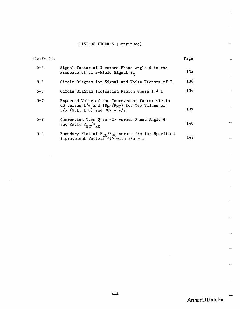
5-4 S igna l Fac tor of I versus Phase Angle 8 i n t h e Presence of an E-Field S igna l SE 134
5-5 C i r c l e Diagram f o r S igna l and Noise Fac tors of I 136
5-6 C i r c l e Diagram I n d i c a t i n g Region where I -< 1 136
5-7 Expected Value of t h e Improvement Fac to r <I> i n dB versus l / a and (REC/RH~) f o r Two Values of $/a (0.1, 1.0) and <8> = 1~12 139
5- 8 Correc t ion T e r m Q t o <I> versus Phase Angle 8 and Ra t io ~ ~ ~ 1 % ~ 140
Boundary P l o t o f R ~ ~ / R ~ ~ versus l / a f o r Spec i f i ed Improvement Fac to r s <I> wi th f3/a = 1 142
x i i - Arthur D Little Inc.
I. EXECUTIVE SUMMARY
A. OBJECTIVE
The o b j e c t i v e of t h i s t a s k was t o s tudy and e v a l u a t e t h e f e a s i b i l i t y
of developing compact t r ansmi t antennas and/or o t h e r means f o r e f f i c i . e n t l y
coupl ing VLF t o MI? r a d i o energy between p o r t a b l e w i r e l e s s communication
u n i t s i n c o a l mines. The Bureau of Mines would l i k e t o ach ieve a
por tab le - to -por tab le range of about 1350 f t . , e s p e c i a l l y i n conductor-
f r e e a r e a s of t y p i c a l U. S. room and p i l l a r c o a l mines, namely a r e a s
w h e r e e l e c t r i c a l conductors such a s power c a b l e s , t r o l l e y l i n e s , and
communication l i n e s a r e absen t . I n t h e presence o f t h e s e conductors ,
ach iev ing t h e d e s i r e d communication range is u s u a l l y n o t a problem. The
1350 f t . conductor-free range corresponds t o t h a t r equ i r ed f o r two miners
t o communicate between t h e l e f tmos t and r igh tmos t e n t r i e s (spaced about
600 f t . a p a r t ) of a seven-entry mine development wh i l e a l s o be ing
s epa ra t ed by a l o n g i t u d i n a l d i s t a n c e of about 1000 f t . a long t h e e n t r i e s .
This r e q u i r e s an area-coverage c a p a b i l i t y t h a t i s n o t adverse ly a f f e c t e d
by t h e presence of t h e l a r g e l y r e c t i l i n e a r g r i d of t unne l s i n t h e c o a l
seam. Thus, t h e frequency band from 30 kHz t o 1 MHz was s e l e c t e d a s
t h e band o f primary i n t e r e s t f o r t h i s i n v e s t i g a t i o n .
B. APPROACH
F i r s t , t h e ranges f o r completely w i r e l e s s communication between
two p o r t a b l e r a d i o s u s ing p r a c t i c a l l y - s i z e d loop antennas i n represen-
t a t i v e c o a l mine environments were es t imated . Antenna technology i n
t h e VLF t o MF band was then a s se s sed i n l i g h t of t h e range, i n t r i n s i c
s a f e t y , and w e a r a b i l i t y requi rements , t o determine t h e most s u i t a b l e
antenna types f o r t h e a p p l i c a t i o n , and whether any of them could
s i g n i f i c a n t l y improve upon t h e o v e r a l l performance p r e d i c t e d f o r t h e
r e f e r e n c e loop an tenna used i n making t h e range e s t i m a t e s . E f f o r t was
a l s o d i r e c t e d i n two r e l a t e d a r e a s . The f i r s t was a s t udy t o determine
whether i n d u c t i v e coupl ing t o cab l e s and o t h e r conduct ing s t r u c t u r e s
i n t h e mine could s u b s t a n t i a l l y i n c r e a s e t h e communications range, s i n c e
such c a b l e s , e t c . , a r e u sua l l y p r e s e n t where men a r e working underground.
Arthur D Little, Inc
The second was a s tudy t o a s s e s s t h e p o t e n t i a l b e n e f i t s of us ing a diver-
s i t y r ecep t ion no i se cance l l i ng technique, t h a t u t i l i z e s both t h e e lec-
t r i c and magnetic f i e l d components of t h e ambient n o i s e , t o s u b s t a n t i a l l y
improve t h e ou tput s igna l - to -noise r a t i o of t h e r e c e i v e r when a p o r t a b l e
u n i t must be opera ted i n t h e v i c i n i t y of a s t r o n g source of e l e c t r i c a l
no i se .
C . FINDINGS AND CONCLUSIONS
1. Wireless Range Est imates
Est imates were made of t h e w i r e l e s s communication range a t t a i n a b l e
i n an underground c o a l mine i n t h e presence of mine generated e l e c t r o -
magnetic n o i s e , f o r man-carried r ad ios of p r a c t i c a l s i z e and source
s t r e n g t h o p e r a t i n g i n t h e frequency band from 10 kHz t o 1 MHz. A
convent ional a i r - co re bandol ier- type loop antenna of s t r e n g t h M = 0.5 t o 2
0 . 7 ampere-m was used a s a r e f e r e n c e source t o gage t h e amount of improve-
ment i n antenna performance r equ i r ed , i f any de f i c i ency i n range, and
t h e r e f o r e s i g n a l s t r e n g t h , must be overcome s o l e l y through improved
antenna design.
It is shown t h a t f o r mines having an e f f e c t i v e conduc t iv i t y of
10-*Mho/m (nea r t h e upper l i m i t f o r c o a l ) , t h e de f i c i ency i n s igna l - to -
n o i s e r a t i o , and thus range, is insuperab le wi th man-carried equipment
a t any frequency i n t h e band of i n t e r e s t . I n mines f o r which a th ree-
l a y e r propagat ion model is a p p l i c a b l e and t h e e f f e c t i v e conduc t iv i t y of -4 t h e c o a l is about 10 Mho/m (near t h e lower l i m i t f o r c o a l ) , t h e de f i -
c i e n c i e s become much more manageable, p a r t i c u l a r l y a t f requenc ies between
about 300 kHz and 1 MHz. Here, moderate improvements i n antenna/
t r a n s m i t t e r des ign and/or r ecep t ion techniques may be a b l e t o provide
modest i nc reases i n c o m u n i c a t i o n range, and reduc t i ons i n b a t t e r y s i z e
and t h e r e f o r e weight of t h e p o r t a b l e u n i t s . However, t h e most l i k e l y
va lue o r range of va lues f o r t h e i n - s i t u conduc t iv i t y of U. S. bituminous
c o a l must s t i l l b e determined b e f o r e a gene ra l conclusion can b e drawn
on t h e percentage of mines i n which t h e d e s i r e d range goal i n completely
conductor-free a r e a s is l i k e l y t o be ach ievable .
I.
Arthur D Little lnc.

2. Antenna Technology
Transmit antenna technology a v a i l a b l e i n t h e VLF through MF bands
was examined f o r i t s u t i l i t y i n p o r t a b l e mine w i r e l e s s r a d i o app l i -
c a t i o n s . I n p a r t i c u l a r , an assessment was made of t h e f e a s i b i l i t y of
developing compact, p o r t a b l e t r a n s m i t antennas t h a t w i l l e f f i c i e n t l y
gene ra t e r a d i o waves i n c o a l mines. The s i z e of such antennas r e l a t i v e
t o wavelength c l a s s i f i e s them a s e l e c t r i c a l l y sma l l antennas which, by
t h e i r very n a t u r e , a r e poor r a d i a t o r s . No major breakthroughs have
occur red , o r a r e l i k e l y t o occur , t o change t h i s f a c t . Thus, t h e VLF-
MF mine w i r e l e s s communication problem is one of op t imiz ing t h e n e a r
f i e l d and i nduc t i on f i e l d coupl ing between two l o o s e l y coupled p o r t a b l e
e l ec t romagne t i c f i e l d t r ansduce r s (antennas) i n t h e phys i ca l and n o i s e
environment of a mine. The problem is made more d i f f i c u l t by t h e mine's
l o s s y conduct ing medium which i n t roduces cons ide rab l e s i g n a l a t t e n u a t i o n .
A s a r e s u l t , t h e choice of a s p e c i f i c antenna should n o t be based
on i t s r a d i a t i o n e f f i c i e n c y . I n s t e a d i t should be based on t h e o v e r a l l
power e f f i c i e n c y and p r a c t i c a l i t y ach ievable by t h e complete t r a n s m i t t e r -
antenna system i n producing t h e l a r g e s t usab le s i g n a l a t t h e d e s i r e d
range w i t h i n t h e p r a c t i c a l c o n s t r a i n t s o f system o v e r a l l s i z e , werght , convenience o f use , i n t r i n s i c s a f e t y , and ruggedness f o r roving miners.
Thus, i t is concluded t h a t convent iona l a i r - co re b a n d o l i e r loop
an tennas , and perhaps a s m a l l f e r r i t e - l o a d e d loop an tennas , w i l l b e t h e
most s u i t a b l e and reasonable choices f o r rov ing miner p o r t a b l e r a d i o
a p p l i c a t i o n s a t f r equenc i e s below about 1 MHz. Furthermore, a t r ansmi t 2
moment of about 2.5 amp-m (peak) appears t o be a p r a c t i c a l upper bound
f o r i n t r i n s i c a l l y s a f e p o r t a b l e u n i t s f o r use by miners. Therefore , t h e
completely w i r e l e s s range goa l o f 1350 f e e t w i l l probably be ach ievable
on ly i n t h e most f avo rab l e c o a l mine propaga t ionand n o i s e environments,
and range c a p a b i l i t i e s w i l l no t be s i g n i f i c a n t l y b e t t e r than t hose 2
p r e d i c t e d f o r u n i t s having a t r ansmi t moment of 0.7 amp-m . For f i x e d
s t a t i o n a p p l i c a t i o n s , hor izonta l -wi re and v e r t i c a l - r o d mode e x c i t e r s
may a l s o o f f e r comparable o r b e t t e r performance t han p l ana r a i r - co re
l oops , b u t in-mine measurements w i l l b e needed t o r e s o l v e t h i s m a t t e r .
Arthur D Little, Jnc.

3. Coupling t o Mine Conductors
To eva lua t e t h e p o t e n t i a l advantages and p r a c t i c a l i t y of extending
mine w i r e l e s s ranges by coupling t o e x i s t i n g conducting s t r u c t u r e s i n
mines, t h e o r e t i c a l coupl ing equat ions were developed. The equat ions
r e l a t e loop antenna s t r e n g t h , frequency, and its d i s t a n c e from two-wire
cables and s t r u c t u r e s , t o t h e cu r r en t and vo l t age induced i n t h a t
s t r u c t u r e by t h e loop antenna. These equat ions al low one t o compute
not only t h e loop-to-structure coupling but a l s o loop-to-loop coupling
v i a t h e two-wire s t r u c t u r e . Resul t s computed f o r t h r e e f requencies
(3, 100, and 1000 kHz) i n d i c a t e t h a t :
performance improves wi th c loseness t o t h e two-wire s t r u c t u r e ,
increased s e p a r a t i o n of t h e wi re s , and inc reas ing frequency up
t o about 0.5 - 1 MHz i n a mine tunnel ;
loop-to-loop communications a long a haulageway appear p r a c t i c a l
i n t h e presence of a t r o l l e y w i r e system and may a l s o be usable
i n t h e presence of untwisted cables and s i n g l e w i r e s a t t ached
t o t h e r i b s ;
ranges of s e v e r a l k i lometers a r e p red ic t ed f o r t h e 200 kHz - 1 MEz band when t h e loops are w i t h i n about 2 meters o f unloaded
.: trolley wire/rails ;
coupl ing t o tw i s t ed p a i r cab le s is seve re ly reduced over t h a t
f o r untwisted p a i r s ;
performance should be s i g n i f i c a n t l y reduced f o r loops loca t ed
i n t unne l s ad j acen t t o t h e one i n which t h e conductors are
loca ted .
4. Noise Cancel l ing Dive r s i ty Reception
A hybr id n o i s e c a n c e l l i n g d i v e r s i t y r ece iv ing technique was
examined t h a t would t r y t o c a p i t a l i z e on t h e h igh l e v e l s of bo th
e l e c t r i c and magnetic f i e l d n o i s e components present i n many p a r t s of
a mine a t t h e f requencies of i n t e r e s t below 1 MHz. It is shown t h a t
i f t h e ins tan taneous c o r r e l a t i o n is h igh enough between t h e n o i s e E and
H f i e l d components, it should be p o s s i b l e t o improve t h e output s igna l -
to-noise performance of a mine wireless system by c a n c e l l i n g a major
po r t ion of t h e H-field n o i s e picked up i n a loop antenna by proper ly
m
Arthur D Little Inc.

combining i t (manually o r au toma t i ca l l y ) wi th t h e E- f ie ld n o i s e picked
up by a small d ipo l e o r whip antenna t h a t would be i n s e n s i t i v e t o H-f ie ld
s i g n a l s and t h e ambient H-f ie ld no i s e . This s e l e c t i v i t y between s i g n a l
and n o i s e is l i k e l y f o r p o r t a b l e u n i t s u s ing loop antennas t h a t gene ra t e
p r i m a r i l y H f i e l d s which couple t o t h e r e c e i v e r of o t h e r p o r t a b l e s
p r i m a r i l y through magnetic induc t i on .
Ca l cu l a t i ons t o d a t e i n d i c a t e t h a t p o t e n t i a l s igna l - to -no ise
improvements between 10-15 dB may be p o s s i b l e when t h e E and H n o i s e
components a r e 80% t o 90% c o r r e l a t e d , a cond i t i on which may p r e v a i l i n
t h e v i c i n t i y of s eve re n o i s e sources . Such a S/N i n c r e a s e could t hen
r e s u l t i n ex tending t h e range o f a w i r e l e s s communications system, o r
reduc ing t h e power r equ i r ed t o a t t a i n a given range i n t h e presence of
h igh ambient e l e c t r i c a l n o i s e n e a r one of t h e r ece iv ing u n i t s . Some
b a s i c f i e l d measurements a r e r equ i r ed t o determine whether t h e degree
of c o r r e l a t i o n between t h e E and H n o i s e f i e l d components i s h igh
enough t o war ran t a more r i go rous a n a l y s i s and f u r t h e r development
e f f o r t .
Arthur D Little, Inc

(This page intentionally l e f t blank)
- Arthur D Little lnc

11. MINE WIRELESS RADIO RANGE ESTIMATES
A . SUMMARY
The f e a s i b i l i t y of ach iev ing a w i r e l e s s communication range of
1 ,350 f t (412 m) i n an underground coa l mine, i n t h e presence of mine
generated e lec t romagnet ic n o i s e , w i th man-carried r ad ios of p r a c t i c a l
s i z e and source s t r e n g t h i n t h e frequency band from 10 kHz t o 1MHz i s
a s se s sed . A convent iona l a i r - co re bandol ier- type loop antenna of s t r e n g t h 2
M = 0.5 t o 0.7 ampere-m i s used a s a r e f e r ence sou rce , t o gage t h e
amount of improvement requi red i f any de f i c i ency i n range,and t h e r e f o r e
s i g n a l s t rength ,mus t be overcome s o l e l y through improved antenna design. -2 It i s shown t h a t f o r mines having an e f f e c t i v e conduc t iv i t y of 10 mo/m
(near t h e upper l i m i t f o r c o a l ) , t h e de f i c i ency i n s igna l - to -noise r a t i o ,
and thus range, i s in supe rab l e (by a v a s t margin) w i th man-carried equip-
ment a t any frequency i n t h e band of i n t e r e s t . I n mines f o r which a th ree-
l a y e r propaga t ion model i s a p p l i c a b l e and t h e e f f e c t i v e conduct iv i ty of
t h e c o a l . i s about loo4 Mho/m (near t h e lower l i m i t f o r coal) , t h e def i c i -
enc i e s become much more manageable, p a r t i c u l a r l y a t f requenc ies between
about 300 kHz and 1 MHz. Here, moderate improvements i n an t enna l t r ans -
m i t t e r des ign and/or r ecep t ion techniques may be a b l e t o provide p r a c t i c a l
s o l u t i o n s . However, t h e most l i k e l y va lue o r range of va lues f o r t h e
i n - s i t u conduc t iv i t y of U.S. bituminous c o a l must s t i l l be determined
be fo re a gene ra l l y a p p l i c a b l e system can be developed f o r ach iev ing t h e
d e s i r e d range goa l i n completely conductor-free a r e a s of mines.
B . INTRODUCTION
The o b j e c t i v e of t h i s chap te r is t o e s t a b l i s h some r e f e r ence l e v e l s
of performance t h a t can be expected i n a mine environment. A wel l -
de f ined , p r a c t i c a l s i z e d antenna t h a t can be convenient ly worn on t h e
body of a mobile miner, namely an a i r - c o r e , mul t i - tu rn bandol ier- type
loop having a t r a n s m i t magnetic moment i n t h e range of 0 .5 t o 2 ampere- 2
meter , i s used a s a r e f e r ence s i g n a l source . The t h e o r e t i c a l f i e l d
s t r e n g t h generated by t h i s source over t h e 1,350 f t range of i n t e r e s t
i s c a l c u l a t e d f o r two e lec t romagnet ic wave propaga t ion models f o r t h e
underground c o a l mine. These s i g n a l l e v e l s a r e then compared wi th
Arthur D Little, lnc.

expected electromagnet ic n o i s e l e v e l s under mine opera t ing condi t ions
t o e s t ima te corresponding ranges of communication. From these ca lcu la-
t i o n s , d e f i c i e n c i e s i n t r a n s m i t t e r s t r e n g t h become apparent , t oge the r
wi th t h e amount of improvement requi red a t each frequency t o achieve t h e
1,350 f t range goal . The p o t e n t i a l f o r overcoming t h e s e d e f i c i e n c i e s
through new developments i n antenna technology i n t h i s frequency band
is d iscussed i n Chapter 111.
I n t h e fo l lowing s e c t i o n s of t h i s chap te r , performance e s t ima te s
a r e made f o r two propagat ion models f o r t h e mine environment; an i n f i n i t e
homogeneous medium model, and a three- layer model c o n s i s t i n g of a horizon-
t a l l a y e r of c o a l surrounded by rock which extends t o i n f i n i t y above and
below t h e coa l .
C. THE HOMOGENEOUS MEDIUM MODEL
This s e c t i o n t r e a t s t h e case where t h e c o a l seam and t h e surrounding
rock a r e considered t o a c t a s one cont inuous, homogeneous, conducting
medium of i n f i n i t e e x t e n t and conduct iv i ty c , i n which an i n f i n i t e s i m a l
loop antenna of magnat~$dipo le moment M is iametfLd. It is a model i n
which t h e presence of a i r spaces represented by t h e r e c t i l i n e a r g r i d of
t unne l s i n t h e c o a l seam and t h e a i r - e a r t h i n t e r f a c e above t h e mine is
ignored, reasonable s imp l i fy ing assumptions f o r t h e f requencies , mine
tunne l c ross -sec t ions , and mine depths of i n t e r e s t . I n each in s t ance we
compute t h e va lue of t h e magnitude of t h e component of magnetic f i e l d
perpendicular t o t h e p lane of t h e loop , f o r observa t ion po in t s which l i e
on a r a d i a l l i n e i n t h e p l ane of t h e loop. We des igna te t h i s component
as IHZl in t h e fol lowing equat ions. For convenient r e f e rence and comparison
wi th t h i s conducting medium case , we have a l s o computed va lues f o r t h e
same magnetic f i e l d component ~ r o d u c e d by t h e same loop when placed i n
an a i r medium.
1. S igna l F i e ld S t rengths
I f r i s t h e d i s t a n c e of t h e observa t ion p o i n t f r o m t h e loop, f
is t h e frequency of ope ra t ion , and M is t h e magnetic d i p o l e moment, then
t h e magnitude of t h e f i e l d componen t l~ I a s a func t ion of d i s t a n c e and z frequency is given f o r both the a i r and conducting medium cases by the
convent ional f i e l d equat ions below (with terms grouped a s shown f o r
convenience).
I
Arthur D Little Inc.

Air Medium
where
and c = (eOIIO)-' is the velocity of light in free space (3)
Conducting Medium
where C = r(oPoo)'= f i r 1 6 (5)
and o is the electrical conductivity of the medium
6 is the skin depth
The conduct ing medium equa t ions a r e t hose t h a t apply when displacement
c u r r e n t s a r e n e g l i g i b l e , a reasonable approximation i n a c o a l / r o c k medium
of assumed c o n d u c t i v i t y a = ~ h o / m a t o p e r a t i n g f r equenc i e s below
a few MHz.
Graphs of t h e f i e l d s t r e n g t h magnitudes a r e p l o t t e d ve r sus f requency,
w i t h range from t h e loop a s a parameter , i n F igures 2-1 and 2-2 f o r a i r -2
and conduct ing media r e s p e c t i v e l y . A nominal va lue of a = 10 Mho/m
was used f o r t h e conduct ing medium (near t h e upper l i m i t f o r c o a l ) . I n
bo th ca se s a sou rce magnetic d i p o l e moment M=NIA of v a l u e 0.5 ampere-meter 2
was used , a conse rva t i ve p r a c t i c a l va lue f o r a man-carried r a d i o . The
p l o t t e d f i e l d s t r e n g t h s may be i n t e r p r e t e d a s peak o r r m s ampli tudes
accord ing ly a s M is e i t h e r t h e peak o r r m s d i p o l e moment. Note t h a t f o r
t h e a i r medium, F igu re 2-1 shows t h a t a t g iven d i s t a n c e t h e magnetic
f i e l d 1 H~ 1 e v e n t u a l l y i n c r e a s e s w i t h i n c r e a s i n g frequency. Th i s occurs
a s t h e r a d i a t i o n f i e l d t e r m exceeds t h e i nduc t i on f i e l d terms, thereby
l e a d i n g t o h i g h e r f i e l d s t r e n g t h s a t h i g h e r f r equenc i e s . F igu re 2-2 shows
t h a t t h e converse i s t r u e i n a conduct ing medium. Namely f o r t h e -2
a = 10 Mho/m case , a s t h e f requency i s inc rea sed , t h e i n c r e a s i n g
r a d i a t i o n f i e l d t e r m i s more than overpowered by an exponen t i a l a t t enua -
t i o n f a c t o r caused by t h e r e s i s t i v e l o s s e s i n t h e medium. Thus, t h e
maximum ach i evab l e ranges a r e s e v e r e l y reduced i n t h e conduct ing medium
over t h a t p o s s i b l e i n a i r , and i t i s seen t h a t i n t h i s conduct ing medium
h i g h e r f i e l d s t r e n g t h s a r e ob ta ined by reducing t h e ope ra t i ng frequency
i n s t e a d of r a i s i n g i t .
Arthur D Little, lnc

lalaw lad dwe 1 al gp u! l Z H l
10 Arthur D Little, Inc

-250
a
a
E
lu
I-
'Y
I-'
?
&----
-
*--
------
-- - -4
. r
= 3
0 - -
M
- M
= 0
.5 a
mp
turn
m
- 'c
oal
= 1
o'~
m
ho
slm
.
r =
dis
tanc
e fr
om
sig
nal l
oo
p in
met
ers
- - Sign
al F
ield
-
Noi
se F
ield
s (m
easu
red
at s
pot f
requ
enci
es
wit
h 1
kHz
band
wid
th i
nstr
umen
tatio
n)
A,-- R
oben
a M
ine
No
. 4,
Fig
s. 4
9-53
, R
ef.
1
- em-,,,
McE
lro
y M
ine,
Fig
s. 4
-28
to 4
-35,
Ref
. 2
- ltm
an
n M
ine
No
. 3,
Fig
s. 9
e, 1
0e,
1 le
, R
ef.
3
-
Fre
quen
cy, k
Hz
Sou
rce:
Art
hu
r D
. L
ittle
, In
c. a
nd N
atio
na
l B
uera
u o
f S
tand
ards
.
FIG
UR
E 2
-2
MA
GN
ET
IC F
IEL
D S
TR
EN
GT
H /
Hz/
FR
OM
A L
OO
P A
NT
EN
NA
IN
A C
ON
DU
CT
ING
ME
DIU
M
AN
D R
MS
MA
GN
ET
IC F
IEL
D N
OIS
E I
N M
INE
S (
NO
RM
AL
IZE
D T
O 2
.5kH
z B
AN
DW
IDT
H)
2. Range Es t imates
a . Sing le Sideband Voice
P l o t t e d i n F igure 2-2 a r e magnetic f i e l d r m s n o i s e l e v e l s measured
i n t h r e e c o a l mines(', 3, f o r comparison w i t h t h e s i g n a l s t r e n g t h
curves. The n o i s e l e v e l s have been normalized f o r a s i n g l e sideband AM
voice system e f f e c t i v e bandwidth of 2.5 kHz. These n o i s e d a t a were a l l
t aken i n mine working s e c t i o n s wi th ins t rumenta t ion having an e f f e c t i v e
bandwidth of 1 kHz a t s p o t f requenc ies . A t t h e Robena and McElroy mines
t h e d a t a were taken about 100 meters from working f aces . The d i p i n
n o i s e l e v e l around 130 kHz a t Robena was concluded t o be a t y p i c a l l y low
and should n o t be considered r e p r e s e n t a t i v e . Both Robena and McElroy
mines employ room and p i l l a r cont inuous mining techniques. A t t h e Itmann
No. 3 mine, d a t a were taken near t h e f ace a r e a of a longwall working
s e c t i o n .
I n F igure 2-3, t h e s i g n a l l e v e l s of F igure 2-2 have been r e p l o t t e d
f o r comparison w i t h samples o f wideband t a p e record ings of magnetic (2)
f i e l d n ~ i s e l e v e l s measured n e a r ope ra t i ng machinery i n fou r mines . The n o i s e l e v e l s have aga in been normalized t o a bandwidth of 2.5 kHz.
F igure 2-5 con ta in s a s i m i l a r comparison of s i g n a l and n o i s e l e v e l s , b u t
f o r no i se l e v e l samples measured i n r a i l haulageways. The n o i s e l e v e l s
i n F igures 2-3 and 2-4 were ob ta ined by narrowband FFT spectrum a n a l y s i s
of wideband t a p e record ings having upper c u t o f f f requenc ies of 100 kHz
( ~ o b e n a ) and 200 kHz (o the r mines).
1. W. D. Bensema, M. Kanda and J. W. Adams, "Electromagnetic Noise i n Robena No. 4 Coal ~ i n e " , NBS Technical Note 654, A p r i l , 1974-
2. M. Kanda, J. W . Adams and W. D. Bensema, "Electromagnetic Noise i n McElroy Mine", NBSIR 74-389, June, 1974.
3. M. Kanda, "Time and Amplitude S t a t i s t i c s f o r Electromagnet ic Noise i n Mines", NBSIR 74-378, June , 1974.
Arthur D Little Inc.

- Signal FieM r = distance from signal loop in meters M = 0.5 amp turn m2 'coal = mhos/m.
C
"Spectra of Noise Fields in Mines, Ref. 2 (measured with wideband tape recording instrumentation) - --- Noise Measurement System Self-Noise
-10 -
--I50 -
-170 -
-190 -
--210 -
0 20 40 60 80 100 120 140 160 1 80 200
Frequency, kHz
Source: Arthur D. Little, Inc. and National Bureau of Standards.
FIGURE 2-3 COMPARISON OF LOOP SIGNAL IN CONDUCTING MEDIUM (FROM FIGURE 2-2) AND MINE NOISE NEAR OPERATING MACHINERY (NORMALIZED TO 2.5kHz BANDWIDTH)
Arthur D Little Inc

4 I 1 I 1 1 I I 1 1 1 0 20 40 60 80 100 120 1 40 1 60 180 200
Source: Arthur D. Little, Inc. and National Buerau of Standards
Frequency, k H z
FIGURE 2-4 COMPARISON OF LOOP SIGNAL I N C;ONDUCTING MEDIUM (FROM FIGURE 2-2) AND MINE NOISE IN HAULAGEWAY (NORMALIZED TO 2.5kHz BANDWIDTH)
Arthur D Little. Inc.

r = 30 -
- M = 1500 amp turn m
'coal = 1 o - ~ mhoslm. - r = distance from signal loop in meters - Signal Field -
Noise Fields (measured at spot frequencies - with -- 1 kHz bandwidth instrumentation) A- - - Robena Mine No. 4, Ref. 1, Figs. 49-53
- a- - - -- McElroy Mine, Ref. 2, Figs. 4-28 to 4-35
rn ltmann Mine No. 3, Ref. 3, Figs. 9e, 10e, I l e -
-
Frequency, kHz
Source: Arthur D. Little, Inc. and National Buerau of Standards.
FIGURE 2-5 MAGNETIC FIELD STRENGTH /Hz/ FROM A LOOP ANTENNA I N A CONDUCTING MEDIUM AND RMS MAGNETIC FIELD NOISE IN MINES (NORMALIZED TO A 10Hz BANDWIDTH)

Examination of F igures 2-2, 2-3 and 2-4 r evea l s ach ievable ranges
i n t h e v i c i n i t y of about 50 meters f o r marginal q u a l i t y convent ional SSB
vo ice communication, and then only above about 100-200 kHz. These range
expec t a t i ons , based on direct- loop-to- loop coupl ing between man-sized -2 loops i n a homogeneous conducting medium of 0 = 10 Mho/m.. (without t h e
a i d of any nearby conductors) i n t h e presence of r e p r e s e n t a t i v e n o i s e
l e v e l s i n ope ra t i ng mines, a r e unacceptably low compared wi th t h e
des i r ed range of 1 ,350 f t (412 m). A t "quiet" t imes o r l o c a t i o n s t h e s e
performance ranges can b e expected t o i n c r e a s e somewhat, bu t probably
no t d r a s t i c a l l y i f t h e mine is n o t i n an emergency power-down condi t ion 2
Inc reas ing t h e t r ansmi t moment from 0.5 t o 2 amp - m w i l l no t make a
s i g n i f i c a n t d i f f e r e n c e e i t h e r . Sec t ion D of t h i s chapter examines t h e
range imp l i ca t i ons f o r a d i f f e r e n t propagat ion model which t o d a t e has
been found t o apply i n s e v e r a l mines.
b. Narrowband Paging
A second r e f e r ence example ( a somewhat extreme one) has a l s o been -2
examined f o r t h e same homogeneous conducting medium having a = 10 ~ h o / m ,
t o s e e i f i t would produce a s i g n i f i c a n t improvement i n range. Namely,
it w a s assumed t h a t t h e very l a r g e t r ansmi t moment (M = 1500 ampere - m 2
f o r a p i l l a r - e n c i r c l i n g s ing l e - tu rn loop) and t h e very narrow band-
width (B = 10Hz) a s soc i a t ed w i th r e c e n t l y developed audio frequency c a l l
a l e r t mine paging systems could be s a f e l y generated and maintained over
t h e 10 kHz - 1 MHz frequency band of i n t e r e s t . Such a t r a n s m i t t e r
s t r e n g t h and con f igu ra t i on might be a s soc i a t ed w i t h a f i xed base s t a t i o n
o r r e p e a t e r . The corresponding s i g n a l and no i se f i e l d s t r e n g t h l e v e l s
were computed and compared w i t h each o t h e r t o determine t h e i nc rease i n
range t h a t would occur. The above s i g n a l l e v e l and bandwidth changes
r e p r e s e n t a 94 dB improvement i n s ignal- to-noise r a t i o . I n p r a c t i c e
such a l a r g e i n c r e a s e w i l l be u n a t t a i n a b l e a t t h e h ighe r f requenc ies
because of t h e h igh vo l t ages r equ i r ed (because of t h e loop inductance)
t o genera te t h e c u r r e n t l e v e l s i n t h e t r ansmi t loop t o produce t h e M of
1500 amp-m2, and because t h e p i l l a r - e n c i r c l i n g loop l y i n g i n t h e horizon-
t a l p l ane is u n s u i t a b l e f o r e x c i t i n g t h e f avo rab l e TEM propagat ion mode
i n a t h r ee - l aye r model, which now appears t o be a more r ep re sena t ive
model f o r c o a l mines.
16 I
rthur D Little Inc.

The s i g n a l f i e l d s t r e n g t h s were c a l c u l a t e d a s b e f o r e , u s ing t h e
i n f i n i t e s i m a l magnetic d i p o l e f i e l d approximat ion, which w i l l be a c c u r a t e
enough f o r e s t i m a t i n g maximum ope ra t i ng ranges beyond 100 meters , i n
s p i t e of t h e r a t h e r l a r g e f i n i t e s i z e of t h e p i l l a r - e n c i r c l i n g loop.
Thus, t h e s i g n a l f i e l d s t r e n g t h curves can be ob ta ined by s c a l i n g up t h e
F igure 2-2 s i g n a l curves , and t h e n o i s e curves can be ob ta ined by seal-
i n g down t h e F igure 2-2 n o i s e curves . The r e s c a l e d s i g n a l and n o i s e
curves a r e p l o t t e d i n F igure 2-5. These curves i n d i c a t e t h a t between
about 200 kHz and 1 MHz, ranges would be l i m i t e d t o about 100-200 meters ,
bu t t h a t between about 10 kHz and 200 kHz, i t may be p o s s i b l e t o ach ieve
communication ranges ou t t o between 200 and 300 meters , which s t i l l f a l l
s h o r t of t h e 1 ,350 f t (412 m) range goa l . Furthermore, t h i s would
r e p r e s e n t on ly t h e " t a l k out" range from a base s t a t i o n . Because of t h e
s i g n i f i c a n t l y lower s i g n a l s t r e n g t h a v a i l a b l e from a man-carried t r ans -
m i t t e r compared t o t h a t a v a i l a b l e from t h e p i l a r mounted t r a n s m i t t e r ,
t h e " t a l k back" range from t h e mobile miner would s t i l l be s u b s t a n t i a l l y
s m a l l e r and inadequate .
Thus, we f i n d t h a t i f t h e mine environment is found t o behave l i k e -2
a homogeneous conduct ing medium having a conduc t iv i t y of 10 Mho/m o r
g r e a t e r , t h e d e s i r e d range goa l w i l l be u n a t t a i n a b l e . However, i t has
been found t h a t some mines may possess much more f avo rab l e wave propa-
g a t i o n c h a r a c t e r i s t i c s t h a t t end t o improve t h e ou t look . These a r e
d i s cus sed i n t h e fo l lowing s e c t i o n of t h i s chap t e r .
Arthur D Little Inc.

D. THE THREE-LAYER MODEL
A second, and more p l a u s i b l e model, namely t h e th ree- layer propa-
g a t i o n model has been developed r e c e n t l y by Arthur D . L i t t l e , Inc. (4, 5 )
t o exp la in t h e unexpectedly f avo rab l e r e s u l t s of r a d i o t ransmiss ion
measurements(6) made a t f r equenc i e s i n t h e 50 kHz t o 1 MHz band wi th
loop antennas i n a conductor-free a r e a of a c o a l mine, Consol idat ion
Coal ' s I r e l a n d Mine near Moundsville, West V i rg in i a . The measurements
i n d i c a t e t h a t communication ranges i n excess of 1,000 f t a r e a t t a i n a b l e
i n t h i s mine when both t r ansmi t and r ece ive loop antennas a r e o r i e n t e d
t o l i e i n a common v e r t i c a l plane. The model which exp la in s t h e observed
behavior is one i n which t h e c o a l is assumed t o have a low conduct iv i ty
compared wi th t h a t of t h e surrounding rock above and below t h e seam.
The propagat ion mode is then considered t o be approximately a d i p o l a r ,
two dimensional TEM mode wi th v e r t i c a l E- f ie ld and c i r cumfe ren t i a l H-
f i e l d i n a h o r i z o n t a l s l o t ( t h e c o a l seam) between two i d e n t i c a l , h igher
conduct ing, h a l f spaces ( t h e rock) . This model, a s d id t h e homogeneous
medium model, ignores t h e presence of t h e mine t unne l s , a good approxi-
mation i n view of t h e l a r g e r a t i o of wavelength t o t unne l dimensions.
The model a l s o r e p r e s e n t s a cons iderab le s i m p l i f i c a t i o n of t h e s t r a t i f i -
c a t i o n of t h e l a y e r s of rock above and below t h e coa l . We do no t in tend
t o j u s t i f y t h i s model o r p r e sen t d e t a i l e d d e r i v a t i o n s here., s i n c e t h a t i s
amply t r e a t e d i n t h e c i t e d r e f e r ences . We only p l an t o exce rp t , summarize,
and use t h e r e s u l t s of t h a t i n v e s t i g a t i o n f o r t he purpose of a s se s s ing
t r a n s m i t t e r requirements t o a t t a i n t h e 1,350 f t (412 m) communication
range goa l .
4. Arthur D. L i t t l e , Inc . , "Propagation of Radio Waves i n Coal Mines" Chapter I V , F i n a l Report on Task F, Task Order No. 1, Contract No. H0346045, October, 1975.
5. A. G. Emslie and R. L. Lagace, "Propagation of Low and Medium Frequency Radio Waves i n a Coal Seam", Radio Science, Vol. 11, No. 4 , pp. 253-261, A p r i l , 1976.
6. T . S. Cory, Summary Data Report No. 2 - "Mine Wire less Propagat ion Tes t Program - I r e l a n d Mine Tes t Data a t Medium Frequency", prepared f o r C o l l i n s Radio Group of Rockwell I n t e r n a t i o n a l f o r U.S. Bureau of Mines under Contract H0346067, Subcontract C-615171.
- Arthur D Little Inc.

1. S igna l F i e l d S t r eng ths
The t h r e e l a y e r model is r ep re sen t ed i n F igu re 2-6 which shows a
c r o s s s e c t i o n of t h e s i m p l i f i e d geometry w i t h t h e t r a n s m i t t i n g and
r e c e i v i n g loop an tennas i n t h e v e r t i c a l p l a n e con t a in ing t h e p a t h of
p ropaga t ion . The conduc t iv i t y , a of t h e coa l seam of t h i c k n e s s 2b i s C '
cons idered t o be s e v e r a l o r d e r s of magnitude l e s s than t h e conduc t iv i t y
a of t h e a d j a c e n t rock. The v e r t i c a l l y - o r i e n t e d t r a n s m i t t i n g loop r antenna produces , a l ong t h e p a t h of t r ansmis s ion i n t h e c o a l seam, a
h o r i z o n t a l magnet ic f i e l d H and an approximately v e r t i c a l e l e c t r i c @
f i e l d EZ . The f i e l d s a r e a lmost cons t an t over t h e h e i g h t of t h e c o a l
seam. I n t h e rock above and below t h e seam t h e f i e l d s d i e o f f expon-
e n t i a l l y i n t h e p o s i t i v e and nega t i ve z -d i r ec t i ons , r e s p e c t i v e l y . A t
l a r g e r a d i a l d i s t a n c e s from t h e antenna t h e f i e l d s decay exponen t i a l l y
a t a r a t e determined by a n e f f e c t i v e a t t e n u a t i o n cons t an t a , which
depends on l o s s e s bo th i n t h e c o a l and i n t h e rock and on t h e d i e l e c t r i c
cons t an t of t h e coa l . There i s a l s o a 1 6 f a c t o r a t l a r g e r a d i a l d i s -
t ances r 'due t o t h e c y l i n d r i c a l spread ing of t h e wave.
The zero-order mode magnetic f i e l d H i n t h e p l ane of t h e t r a n s m i t t i n g @
loop is given by
where
M = N I A i s t h e magnetic moment of t h e t r a n s m i t t i n g loop an tenna
be = b + 112 6r i s t h e e f f e c t i v e ha l f -he igh t of t h e c o a l seam
6r = Z - d i r e c t i o n s k i n dep th i n t h e rock
k = 6 - i a i s t h e complex propaga t ion cons t an t i n t h e r a d i a l d i r e c t i o n r
Hi2) ' ( k r ) = d e r i v a t i v e of t h e f i r s t o r d e r Hankel f u n c t i o n f o r a n outgoing wave
Arthur D Little Inc.

Rock Or Approximate Field Directions
h I --- -.
XMTR E~ 1 t RCVS l - c t ~ i ,
// -7 2b Coal Seam 0 E
c, c 1 1, ) I *.
+ -.-- .-
Rock or Source: Arthur D. Little, Inc.
FIGURE 2-6 THREE LAYER MODEL GEOMETRY FOR LOW AND MEDIUM FREQUENCY RADIO WAVE PROPAGATION
-80 0 50 100 150 200 250 300 350 400
Distance, (meters)
Coal Seam Height 2b = 2 Meters - Loop Transmit Moment M = 0.7 amp -m2
For oc= 1 . 4 ~ 1 o - ~ Mholm
Values of Coal Permittivity and Surrounding Rock Conductivity are Identical for all Curves, Namely Kc = 7, or = 1.0 Mholm
Source: Arthur D. Little, I nc.
FIGURE 2-7 THEORETICAL MAGNETIC FIELD STRENGTH PLOTS VERSUS DISTANCE AND FREQUENCY FOR THREE LAYER MODEL FOR TWO VALUES OF COAL CONDUCTIVITY, oc = 1.4 x 10⁻⁴ M ~ O I ~ AND O, = 10-2 M ~ O I ~
111
Arthur D Little Inc.
A d e t a i l e d d e r i v a t i o n f o r , t o g e t h e r wi th formulas f o r t h e phase and
a t t e n u a t i o n cons t an t s B and a expressed i n terms of t h e c o n d u c t i v i t i e s
(ac ,a r ) of t h e coa l and t h e rock, p e r m i t t i v i t y K of c o a l , t h e frequency C
f and t h e ha l f -he ight b of t h e c o a l seam a r e given i n r e f e r ences 4 and 5.
The common r a d i a l s k i n depth i n bo th c o a l and rock i s 6 = l / a . The b e s t o v e r a l l f i t of t h e above propagat ion model t o t h e I r e l a n d
mine experimental d a t a was found (4 , 5)
t o occur f o r c o a l and rock con-
d u c t i v i t i e s of 1 .4 x loe4 Mho/m and 1.0 Mho/m, r e s p e c t i v e l y , us ing an
assumed c o a l d i e l e c t r i c cons t an t of 7 ( a va lue c o n s i s t e n t wi th d i e l e c t r i c
cons t an t d a t a ob ta ined by NBS) C 7 ) ~ l t h o u g h t h e s e va lues of conduc t iv i t y
a r e r ea sonab le f o r bituminous c o a l and rock s h a l e s , they do l i e c l o s e -4
t o extreme va lues f o r each. Namely, t h e v a l u e of 1 .4 x 10 Mho/m f o r
t h e conduc t iv i t y a of t h e c o a l r equ i r ed t o make t h e theory f i t t h e C
experimental d a t a l ies w i t h i n t h e lower p a r t of t h e range of conduc t iv i t y
va lues f o r bituminous c o a l s ; whereas t h e conduc t iv i t y v a l u e 0 of 1 .0 r
Mho/m requ i r ed of t h e ad j acen t rock l a y e r s , a l though h igh , l i e s w i t h i n
t h e uppermost p a r t of t h e range of r epo r t ed conduc t iv i t y va lues f o r some (8) types of s h a l e s and s l a t e s under c e r t a i n cond i t i ons .
Using t h e s e conduc t iv i t y va lues , t h e o r e t i c a l magnetic f i e l d s t r e n g t h
curves have been computed and p l o t t e d i n F igu re 2-7 a t t h r e e f requenc ies
(57.5, 350, and 920 kHz) f o r a t r ansmi t loop source s t r e n g t h of M = 0.7
ampere - m2 which i s o r i e n t e d and pos i t i oned a s shown i n F igu re 2-6 i n
a high-coal seam of t h i cknes s 2b = 2 meters. Also p l o t t e d f o r comparison
i n F igure 2-7 a r e f i e l d s t r e n g t h curves a t t h e t h r e e f r equenc i e s of 10 ,
100, and 1000 kHz f o r t h e same source s t r e n g t h and con f igu ra t i on , seam
th i cknes s , and rock conduc t iv i t y , b u t f o r t h e s u b s t a n t i a l l y h ighe r c o a l
7. D. A. E l l e rb ruch and J. W , Adams, "Microwave Measurement of Coal Layer ~ h i c k n e s s " , Nat. Bureau Stand. (U.S.) NBSIR 74-387, September, 1974.
8. E. I. Parkhomenko, Chapter 111, E l e c t r i c a l R e s i s t i v i t y of Rocks, E l e c t r i c a l P r o p e r t i e s of Rocks, T rans l a t ed from Russian and Edi ted by G. V. K e l l e r , Plenum P r e s s , N.Y. 1967
Arthur D Little Inc.
-2 conduc t iv i t y of o = 10 Mho/m used i n t h e homogeneous medium model i n r Sec t i on C o f t h i s chap te r . The h ighe r va lue o f oc l i e s w i t h i n t h e
upper p a r t of t h e range of va lue s f o r bituminous coa l (8 ) . Examination
of F igure 2-7 r e v e a l s t h a t d ramat ic changes i n propagat ion l o s s can occur -4 a s t h e conduc t iv i t y of t h e c o a l i s inc rea sed from 10 t o l om2 Mho/m.
The low c o a l conduc t iv i t y produces a s u b s t a n t i a l l y lower s i g n a l a t t enua -
t i o n r a t e and on ly moderate v a r i a t i o n s of s i g n a l s t r e n g t h w i th frequency
f o r t h e i n d i c a t e d ranges o f d i s t a n c e and frequency. On t h e o t h e r hand,
t h e h ighe r c o a l conduc t iv i t y r e s u l t s i n s u b s t a n t i a l l y i nc r ea sed a t tenua-
t i o n r a t e s and l a r g e v a r i a t i o n s w i th f requency, t h a t i n t u r n cause t h e
s t r o n g e s t s i g n a l s t o occur a t t h e lowest f r equenc i e s , a s i n t h e homo-
geneous model.
2 . Range Es t imates f o r FM Voice
P l o t t e d i n F igures 2-8 and 2-9 a r e comprehensive n o i s e p l o t s which we
have used t o g e t h e r wi th t h e f i e l d s t r e n g t h curves of F igure 2-7 t o a r r i v e
a t new range e s t i m a t e s f o r w i r e l e s s vo i ce communication w i th man-carried
pe r sona l r a d i o systems i n mines. We chose i n t h i s i n s t a n c e , a narrowband
FM r a d i o 4 communication system having an IF bandwidth B = 12 kHz, r e c e i v e r
n o i s e f i g u r e F = 6 dB, t r a n s m i t magnetic moment M = 0.7 amp-m2,and loop 2
e f f e c t i v e tu rns -a rea NA = 1 m , s i m i l a r t o a system p r e s e n t l y be ing dev-
e loped f o r w i r e l e s s mine communication a p p l i c a t i o n s by C o l l i n s Radio Group
on Bureau of Mines Cont rac t H0346047. The r m s n o i s e l e v e l s used t o
c h a r a c t e r i z e t h e mine e lec t romagnet ic n o i s e environment i n F igures 2-8
and 2-9 were de r ived from samples o f magnetic f i e l d , time-averaged,
r m s n o i s e l e v e l s measured (with 1 kHz bandwidth i n s t rumen ta t i on ) a t
s p o t f r equenc i e s i n t h e f requency range of i n t e r e s t i n t h r e e c o a l mines
by Bensema, Kanda, and Adams 2 ' of t h e Nat iona l Bureau of Standards .
I n t h e f requency band o f i n t e r e s t , t h e average r m s n o i s e l e v e l s gene ra l l y
decrease a t a r a t e on t h e o r d e r of l / f wi th i n c r e a s i n g frequency, and
e x h i b i t r e l a t i v e l y l a r g e v a r i a t i o n s dur ing t y p i c a l mine work s h i f t s . The
magnitude of t h e s e long term v a r i a t i o n s i n average r m s l e v e l a l s o decrease
w i th i n c r e a s i n g frequency i n t h e LF t o MF band,commonly be ing on t h e o rde r
o f 45-50 dB a t f r equenc i e s below about 100 kHz and dec rea s ing t o about
25-30 dB a t f r equenc i e s around 1 MHz.
9. W. D. Bensema, M. Kanda and J . W . Adams, "Electromagnet ic Noise i n Itmann Mine", Nat. Bur. Stand. (U.S.) NBSIR 74-390, June , 1974.
Arthur D Little Inc

Plotted Noise Levels Normalized to 12kHz Bandwidth - Measured with 1 kHz Instrumentation Bandwidth - - - Vertical Field Component - . - Vertical Component - "Quiet Time"
Horizontal Field Component
McElroy Mine - Continuous Miner Section and Nearby Rail Haulagewey
o Near end of rail haulage line u Near intersection of rail haltlageway and conveyor belt 4 Near operating continuous mining machine
Near section power distribution center
Frequency in kHz
Source: National Bureau of Standards (Report NBSl R 74-389, June 1974)
FIGURE 2-8 REPRESENTATIVE RMS MAGNETIC FIELD NOISE LEVELS MEASURED I N THE McELROY COAL MINE
Arthur D Little. Inc

Plotted Noise Levels Normalized to 12kHz Bandwidth - Measured with 1 kHz Instrumentation Bandwidth - - Vertical Field Component - - - Vertical Component - "Quiet Time" -Horizontal Field Component
ltmann Mine - Longwall Panels
4 At longwall face head end - Farley panel 230 f t from longwall face - Farley panel
n At longwall face head end near main conveyor belt - Cabin Creek panel
Robena Mine - Rail Haulageway serving continuous miner section. All curves for same location approximately 300 meters from face area
C ) Horizontal (E-W) - 1st day + F Horizontal (N-S) - 1st day Q Vertical - 1st day 'ti Vertical - 2ndday
t Note: NBS be1ie;es that these three data points at 130kHz on the 1st day at Robena were atypically low and therefore should not be considered
Frequency in kHz
-50
-60
-70
Source: National Bureau of Standards (Reports NBS Technical Note 654, April 1974 Robena; and NBSlR 74-390, June 1974, Itmann)
- representative.
-
i I I 1 I I I I 1 1 I
FIGURE 2-9 REPRESENTATIVE RMS MAGNETIC FIELD NOISE LEVELS MEASURED I N THE ROBENA AND ITMANN COAL MINES
I*
Arthur D Little. Inc.

The w i r e l e s s communication ranges a r e e s t ima ted f o r t h e above r a d i o
system and n o i s e parameters and a r a d i o c i r c u i t g rade of performance goa l
w i t h i n t h e C i r c u i t Mer i t F igu re /I3 c l a s s i f i c a t i o n , t h e minimum f i g u r e
normally cons idered f o r commercial r a d i o s e r v i c e . To o b t a i n t h i s l e v e l
of performance t h e minimum average r m s c a r r i e r - t o - n o i s e r a t i o a t t h e
r e c e i v e r must b e a t l e a s t 10 dB o r b e t t e r f o r t h e mine n o i s e cond i t i ons
p r e v a i l i n g du r ing t h e communication i n t e r v a l s .
The range e s t i m a t e s a r e shown i n Table 2-1 f o r active-mine e l e c t r o -
magnetic n o i s e cond i t i ons and q u i e t rece iver -no ise - l imi ted cond i t i ons .
Table 2-1 shows t h a t on ly very s h o r t and inadequa te communication ranges
a r e p r ed i c t ed f o r a l l n o i s e cond i t i ons and f r equenc i e s f o r t h e h igh con- -2
d u c t i v i t y c o a l c a se ( a = 1 . 0 x 10 Mho/m), a s was t h e ca se f o r t h e C
homogeneous medium model. The extremely high r a t e s of s i g n a l a t t e n u a t i o n
f o r t h i s c a s e a l s o make communication ranges very i n s e n s i t i v e t o even
l a r g e upward o r downward changes i n l o c a l l e v e l s of average rms e l e c t r o - -4
magnetic n o i s e . For t h e low conduc t iv i t y c o a l c a se ( u = 1.4 x 10 Mho/m), C
t h e communication ranges a r e s u b s t a n t i a l l y i nc r ea sed t o more p r a c t i c a l
v a l u e s t h a t approach t h e 412 m (1,350 f t ) range goa l . However, t h e s e
extended ranges a r e a l s o more s e n s i t i v e t o v a r i a t i o n s i n l o c a l rms
e lec t romagnet ic n o i s e l e v e l s , because of t h e g r e a t l y reduced r a t e s o f
s i g n a l a t t e n u a t i o n when t h e c o a l conduc t iv i t y is low. Th i s e f f e c t is
i l l u s t r a t e d i n Table 2-1 by t h e wide spans i n es t imated ranges under
active-mine n o i s e cond i t i ons . Active-mine n o i s e l e v e l s can a l s o
o c c a s i o n a l l y f a l l below i n t r i n s i c r e c e i v e r n o i s e l e v e l s . When t h i s
occu r s , t h e maximum range w i l l be l i m i t e d by, and i d e n t i c a l t o , t h a t
d i c t a t e d by r e c e i v e r n o i s e n o t mine no i s e . These rece iver -no ise - l imi ted
ranges a r e a l s o shown i n Table 2-1.
Arthur D Little, Inc.

TABLE 2-1
RANGE ESTIMATES FOR WIRELESS COMMUNICATION WITH PERSONAL PORTABLE FM RADIOS I N A HIGH-COAL SEAM
(Seam Height of 2m, and Kc = 7 , bounded by rock of conduc t iv i t y o = r
-2 1 .0 Mho/m, f o r c o a l c o n d u c t i v i t i e s of 1 . 0 x 10 and 1.4 x Mho/m)
Frequency (kHz)
Coal Conduct ivi ty 0 (Mho/m)
C
Source: Ar thur D . L i t t l e , Inc .
Communication Range i n M e t e r s ( f t ) Noise Condit ions
Act ive Receiver Noise Mine Noise
- Arthur D Little lnc.

3. Discuss ion of Imp l i ca t i ons
The f i n d i n g s of t h e t h r e e l a y e r model based on t h e I r e l a n d mine
exper imenta l d a t a i n d i c a t e t h a t communication ranges w i t h i n s t r i k i n g
d i s t a n c e of t h e 1 ,350 f t (412 m) goa l a r e a t t a i n a b l e under some n o i s e
cond i t i ons i n a t l e a s t one mine having t h e r i g h t combination of rock
and c o a l c o n d u c t i v i t i e s , i n p a r t i c u l a r , a low va lue of c o a l conduc t iv i t y .
I f t h i s behavior i s found t o be common i n c o a l mines, i t is conce ivab le
t h a t t h e range goa l could be reached through the c l e v e r a p p l i c a t i o n of
of c u r r e n t l y a v a i l a b l e antenna and t r a n s m i t t e r technology. However,
i t is r epo r t ed '8 t h a t t h e conduc t iv i t y of c o a l can t a k e on a wide range of
v a l u e s , encompassing a t l e a s t two o r d e r s of magnitude, which could
r e s u l t i n d i f f e r e n t seams o r mines w i t h i n t h e same seam having d r a s t i c a l l y
d i f f e r e n t a t t a i n a b l e communication ranges . Therefore , i t i s important
t o determine whether t h e f avo rab l e I r e l a n d mine cond i t i ons a r e t y p i c a l
o r excep t iona l f o r bituminous c o a l mines i n t h e United S t a t e s . This
should be accomplished by performing s i m i l a r p ropaga t ion measurements
i n s e v e r a l more c o a l mines i n s e v e r a l of t h e major c o a l seams, t o o b t a i n
d a t a from mines having bo th s i m i l a r and d i f f e r e n t geo log i ca l p r o p e r t i e s
r ega rd ing bo th t h e c o a l seam and t h e sur rounding rock. Only t hen w i l l
i t b e p o s s i b l e t o con f iden t ly determine t h e most f avo rab l e o p e r a t i n g
frequency, and t h e a s s o c i a t e d performance l i m i t s , f o r a mine w i r e l e s s
communication system us ing c u r r e n t l y a v a i l a b l e technology i n t h e 10 kHz
t o 1 MHz band.
Such a measurement program has been de f ined and i s p r e s e n t l y be ing
implemented f o r t h e Bureau of Mines by a measurement and a n a l y s i s team
c o n s i s t i n g of T. Cory/Spectra Assoc i a t e s /Co l l i n s Radio Group on
Cont rac t H0366028 and Arthur D. L i t t l e , I n c . , on Cont rac t H0346045, Task
Order No. 4 , r e s p e c t i v e l y . The pre l iminary f i n d i n g s t o d a t e i n d i c a t e
t h a t two o t h e r mines a l s o i n no r the rn West V i r g i n i a and i n t h e P i t t s b u r g h
seam e x h i b i t behavior and c o a l c o n d u c t i v i t i e s s i m i l a r t o t h a t found i n
t h e I r e l a n d mine, wh i l e ano the r mine i n I l l i n o i s i n t h e He r r in No. 6
seam e x h i b i t s s i g n i f i c a n t l y h i g h e r s i g n a l a t t e n u a t i o n r a t e s by about a -3 f a c t o r of t h r e e and a c o a l conduc t iv i t y of about 10 Mho/m. Thus, t h e
i s s u e remains unresolved a t t h e t ime of t h i s w r i t i n g . However, i f l a r g e
Arthur D Little, lnc
v a r i a t i o n s i n conduc t iv i t y t u r n ou t t o be common from mine-to-mine, i t
is u n l i k e l y t h a t improved antenna technology a lone w i l l eve r be capable
of p rov id ing t h e s i g n i f i c a n t improvements i n system performance t h a t w i l l
be r equ i r ed f o r 10 kHz t o 1 MHz ope ra t i on i n mines w i t h h igh conduc-
t i v i t y c o a l . An assessment of t h e l i k e l y impact of antenna technology
on performance is d i s cus sed i n t h e fo l lowing chap t e r .
It should be noted t h a t t h e qu ie t -a rea range p r e d i c t i o n s of
Table 2-1 should be most a p p l i c a b l e f o r conductor f r e e a r e a s such a s
t h e p a r t of t h e I r e l a n d mine i n which t h e s i g n a l propagat ion measurements
were made; whereas t h e ac t i ve - a r ea range p r e d i c i t o n s a r e probably pes-
s i m i s t i c , because t h e a c t i v e , no i sy a r e a s a r e gene ra l l y t hose where con-
duc to r s such a s t r o l l e y w i r e / r a i l s and power and te lephone c a b l e s a r e
a l s o p r e s e n t . I n t h e l a t t e r s i t u a t i o n one would expect t h a t communica-
t i o n ranges could be cons iderab ly i nc r ea sed by t h e lower- loss t ransmiss ion
l i n e t ype of propagat ion made p o s s i b l e by t h e i n d u c t i v e coupl ing of t h e
f i e l d s from man-carried loops t o such nearby conductors . S ing l e con-
duc to r s o r c ab l e s w i l l a c t a s one element of a t ransmiss ion l i n e , w i t h
t h e h igh ly conduct ing rock and/or moderately conduct ing c o a l s e r v i n g a s
t h e r e t u r n c u r r e n t p a t h , wh i l e t r o l l e y l i n e s have t h e r a i l s a s r e t u r n
conductors . Since miners r e q u i r i n g r a d i o communications a r e very l i k e l y
t o be working i n t h e v i c i n i t y of such conduct ing s t r u c t u r e s , t h i s s i t u a -
t i o n , a s opposed t o t h e completely conductor-free s i t u a t i o n , may become
an e q u a l l y important o p e r a t i o n a l requirement i n f l u e n c i n g t h e choice of
f requency. Therefore , t h e coupl ing of loop antennas t o two-wire t r ans -
miss ion l i n e s t r u c t u r e s is t r e a t e d i n Chapter I V . On t h e o t h e r hand,
methods of reduc ing t h e d e l e t e r i o u s e f f e c t s of mine genera ted r a d i o
n o i s e should n o t be overlooked a s a means of improving t h e s igna l - to -
n o i s e performance and t hus t h e communication range. For example, t h e
e f f e c t i v e l e v e l of rece ived n o i s e can i n some ca se s be reduced by up t o
10-20 dB by s imple p roces s ing , such a s c l i p p i n g and b lanking , i f t h e
n o i s e is h i g h l y impuls ive i n n a t u r e . The p o t e n t i a l b e n e f i t s of y e t
ano the r method, a s p e c i a l n o i s e c a n c e l l i n g d i v e r s i t y r ecep t ion technique
t h a t may be p a r t i c u l a r l y s u i t e d t o t h e mine n o i s e environment, a r e pre-
s en t ed i n Chapter V.
Arthur D Little Inc.

111. ANTENNA TECHNOLOGY
A. SUMMARY
Transmit antenna technology a v a i l a b l e i n t h e VLF through MF bands
is examined f o r i t s u t i l i t y i n p o r t a b l e mine w i r e l e s s r a d i o a p p l i c a t i o n s .
I n p a r t i c u l a r , an assessment is made of t h e f e a s i b i l i t y of developing
compact, p o r t a b l e t r ansmi t an tennas t h a t w i l l e f f i c i e n t l y genera te
r a d i o waves i n c o a l mines. The s i z e of such antennas r e l a t i v e t o wave-
l e n g t h c l a s s i f i e s them a s e l e c t r i c a l l y small an tennas which, by t h e i r
very n a t u r e , a r e poor r a d i a t o r s . No major breakthroughs have occur red ,
o r a r e l i k e l y t o occur , t o change t h i s f a c t . Thus, t h e VLF-MF mine
w i r e l e s s communication prcblem is one of op t imiz ing t h e n e a r f i e l d and
i nduc t i on f i e l d coupl ing between two l o o s e l y coupled p o r t a b l e e l e c t r o -
magnetic f i e l d t r ansduce r s (an tennas) i n t h e p h y s i c a l and no<se environ-
ment o f a mine. The problem is made more d i f f i c u l t by t h e mine's l o s s y
conduct ing medium which i n t roduces cons ide rab l e s i g n a l a t t e n u a t i o n .
The choice of a s p e c i f i c antenna should , t h e r e f o r e , n o t be based
on i t s r a d i a t i o n e f f i c i e n c y . I n s t e a d i t should be based on t h e o v e r a l l
power e f f i c i e n c y and p r a c t i c a l i t y ach ievable by t h e complete t r a n s m i t t e r -
antenna system, i n producing t h e l a r g e s t u sab l e s i g n a l a t t h e d e s i r e d
range w i t h i n t h e p r a c t i c a l c o n s t r a i n t s o f system o v e r a l l s i z e , weigh t ,
convenience of use , i n t r i n s i c s a f e t y , and ruggedness f o r rov ing miners.
Thus, i t is concluded t h a t convent iona l a i r - c o r e b a n d o l i e r loop an tennas ,
and perhaps s m a l l e r f e r r i t e - l o a d e d loop an tennas , w i l l con t inue t o be
t h e most s u i t a b l e and reasonable choice f o r rov ing miner p o r t a b l e r a d i o
a p p l i c a t i o n s a t f requenc ies below about 1 MHz. Furthermore, a t r ansmi t
moment o f about 2.5 amp-m2 (peak) appears t o be a p r a c t i c a l upper bound
f o r i n t r i n s i c a l l y s a f e p o r t a b l e u n i t s f o r u s e by miners. Thus, t h e
completely w i r e l e s s range c a p a b i l i t i e s w i l l no t be s i g n i f i c a n t l y b e t t e r 2
t han t hose p r e d i c t e d f o r u n i t s having a t r ansmi t moment of 0.7 amp-m . For f i x e d s t a t i o n a p p l i c a t i o n s , ho r i zon t a l -w i r e and v e r t i c a l - r o d mode
e x c i t e r s may a l s o o f f e r comparable o r b e t t e r performance than p l a n a r
a i r - co re l oops , bu t in-mine measurements w i l l b e needed t o r e s o l v e t h e
ma t t e r .
Arthur D Little, lnc.

The fo l lowing s e c t i o n s of t h i s chap t e r t r e a t some of t h e b a s i c
p r i n c i p l e s and l i m i t a t i o n s of sma l l antennas ope ra t i ng below 1 MHz i n
bo th f r e e space and conduct ing media, t o g e t h e r w i th an overview o f
s p e c i f i c antenna t ypes cons idered f o r manpack p o r t a b l e a p p l i c a t i o n s and
f o r base s t a t i o n a p p l i c a t i o n s . The t ypes of antennas t r e a t e d a r e t h e
c l a s s of e l e c t r i c a l l y sma l l antennas i n gene ra l and, s p e c i f i c a l l y ,
convent iona l whip an tennas , a c t i v e whip an tennas , convent iona l a i r - co re
loop bando l i e r an tennas , f e r r i t e loaded l oops , s p e c i a l l y resona ted mult i -
t u r n a i r co re l oops , s e l f - r e sonan t a i r - co re h e l i c a l loop an tennas ,
hor izonta l -wi re mode e x c i t e r s , and v e r t i c a l - r o d mode e x c i t e r s . There
is an e x t e n s i v e body of publ i shed r e f e r ence in format ion which covers
t h e s u b j e c t ma t t e r i n cons ide rab l e d e t a i l . The approach taken i n t h i s
chap t e r is t o p rov ide an overview of t h i s antenna technology and i t s
s i g n i f i c a n c e t o t h e mine communications problem a t hand. The r e a d e r is
r e f e r r e d t o t h e s p e c i f i c r e f e r ences t o o b t a i n a more d e t a i l e d t rea tment
of t h e m a t e r i a l .
Arthur D Little. lnc

B. ELECTRICALLY SMALL ANTENNAS
The d e s i r e is t o o b t a i n a s m a l l , l i g h t w e i g h t , unobt rus ive , e f f e c t i v e
antenna t h a t can be convenien t ly worn by a rov ing miner f o r u se w i t h a
pe r sona l r a d i o o p e r a t i n g somewhere i n the VLF t o MF range of 10 kHz t o
1000 kHz ( 1 MHz). The an t enna ' s impedance c h a r a c t e r i s t i c s should a l s o
be r e l a t i v e l y una f f ec t ed by t h e an t enna ' s p o s i t i o n on t h e miner ' s body
and t h e an t enna ' s proximity t o h i s body o r s t r u c t u r e s found i n under-
ground c o a l mines.
Resonant l e n g t h d i p o l e s , monopoles, and loops have maximum dimensions
on t h e o r d e r o f a q u a r t e r t o one-half wavelengths , which make them good
r a d i a t o r s , namely, good coup le r s of power from a t r a n s m i t t e r t o t h e
sur rounding space . They produce r a d i a t i o n r e s i s t a n c e s t y p i c a l l y on t h e
o r d e r of 35 t o 80 ohms and ze ro n e t energy s t o r a g e , o r r e a c t i v e impedance,
a t t h e i r resonant l e n g t h f requenc ies . The re fo re , they can ach ieve very
h igh e f f i c i e n c i e s , b e convenien t ly d r iven from convent iona l sou rce s , and
e a s i l y meet convent iona l s ingle-channel bandwidth requirements .
E l e c t r i c a l l y s m a l l an tennas p r e s e n t a cons ide rab ly d i f f e r e n t and
more d i f f i c u l t de s ign problem than t h e more convent iona l t ype of resonant
l e n g t h an tennas . An e l e c t r i c a l l y s m a l l antenna is de f ined a s one whose
s i z e is a s m a l l f r a c t i o n of t h e wavelength, more s p e c i f i c a l l y l e s s t han
1 /10 of a wavelength. Such an tennas possess fundamental l i m i t a t i o n s on
t h e i r e l e c t r i c a l c h a r a c t e r i s t i c s and performance t h a t a r e d i r e c t l y
a t t r i b u t a b l e t o t h e i r s i z e compared t o wavelength a lone . P o r t a b l e
an tennas f o r rov ing miner a p p l i c a t i o n s a t f r equenc i e s below 1 MHz f a l l
w e l l w i t h i n t h e sma l l an tenna s i z e l i m i t s . Therefore , t h e i r performance
w i l l i n f a c t b e governed by t h e l i m i t a t i o n s and c h a r a c t e r i s t i c s imposed
on e l e c t r i c a l l y small an tennas .
1. E l e c t r i c a l Smallness
F r e e space wavelengths f o r o p e r a t i n g f r equenc i e s from 10 kHz t o
1000 kHz t a k e on va lues of 30,000 t o 300 meters r e s p e c t i v e l y . Comparing
t h e s e wavelengths t o t h e maximum conce ivab le dimension d = 1 meter f o r
a pe r sona l an tenna worn by a rov ing miner , we g e t 1 < d < 1 - - - 30,000 X 300 '
Arthur D Little, Jnc.

which immediately p laces such an antenna we l l i n s i d e t h e category of
" e l e c t r i c a l l y small" antennas, namely, antennas having d < - The 10 ' more t h e s i z e of an antenna is decreased wi th r e spec t t o wavelength t h e
more i t behaves a s a high-Q, lumped-element energy s t o r a g e device and
a s a very poor r a d i a t o r of power t o t h e surrounding space. These
l i m i t a t i o n s a r e fundamental and a r e imposed by t h e antenna 's s i z e
compared t o wavelength, a s i l l u s t r a t e d i n a c l a s s i c paper by Chu (1) in
1948 and by ~ a r r i n ~ t o n ' ~ ) and Wheeler. ( 3 9 4 ) ~ h u s , e l e c t r i c a l l y smal l ,
l o s s l e s s , whip-type d ipo le antennas behave a s capac i to r s , and loop-type
antennas behave a s inductors . Thei r input impedances a r e h ighly
r e a c t i v e and have only a very small r e s i s t i v e p a r t defined a s t h e
r a d i a t i o n resis tance--a r e s i s t a n c e whose va lue decreases r ap id ly with
decreas ing frequency ( i . e . , i nc reas ing wavelength).
2. Radiat ion Resis tance
The r a d i a t i o n r e s i s t a n c e Rr i s a measure of t h e power r a d i a t e d by
an antenna. It i s given by (5)
fo r d ipo le and loop antennas r e spec t ive ly , where h i s t h e e f f e c t i v e e
he igh t of t h e d ipo le and N and A a r e t h e number of t u r n s and a r e a of
t h e loop. Note t h e s t r o n g inve r se dependence on wavelength. The
r a d i a t i o n r e s i s t a n c e Rr i s t h e r e a l p a r t of t h e inpu t impedance of a 1 2 l o s s l e s s antenna, and -I Rr r ep resen t s t h e r e a l power r ad ia t ed . 2 0
Namely :
where Pr i s t h e t o t a l r ad ia t ed power computed by i n t e g r a t i n g t h e
electromngnetic power dens i ty i n t h e f a r f i e l d over t h e su r face of a sphere
concen t r i c wi th t h e antenna, and I. is t h e antenna input cu r ren t which
produces t h e r a d i a t e d f i e l d . Subs t i tu t ing i n t o (I) , (2 ) , and (3)
p r a c t i c a l antenna dimensions o f 0 . 5 meter diameter f o r a 10-turn
loop, a 0 -25 meter e f f e c t i v e he ight*for a d ipo le , and a 1 ampere
input cu r ren t t o each from a p o r t a b l e mine w i r e l e s s u n i t opera t ing
. a t 300 kHz, w e f inif" t h a t t h e r a d i a t i o n r e s i s t a n c e s and r ad ia t ed powers ------------------- *For an e l e c t r i c a l l y smal l unloaded d ipo le having a t r i a n g u l a r d i s t r i b u t i o n of cu r ren t which is maximum a t t h e te rminals and zero a t t h e ends, t h e e f f e c t i v e he igh t is one-half t h e d ipo le length . -
Arthur D Little, lnc.

a r e : -6
R = 5 . 5 x 1 0 ohm re
-9 Rre = 1 .5 x 10 ohm
f o r t h e d i p o l e and loop an tenna r e s p e c t i v e l y . A t a frequency of 30 kHz,
t h e upper boundary of t h e VLF band, t h e above va lues would of course b e
f u r t h e r reduced by a f a c t o r of - f o r t h e d i p o l e and 100 f o r t h e
10,000 loop. When compared w i th t h e r e s i s t i v e l o s s e s a s s o c i a t e d w i th p r a c t i c a l
an tennas , t h e s e r a d i a t i o n r e s i s t a n c e s become i n s i g n i f i c a n t . This f a c t
accounts f o r t h e extremely low e f f i c i e n c i e s a t t a i n a b l e from man-carried
an tennas a t t h e s e low o p e r a t i n g f r equenc i e s . Thus, o t h e r f a c t o r s t a k e
on a much g r e a t e r importance than e f f i c i e n c y i n forming a b a s i s f o r
an tenna s e l e c t i o n .
3. E f f i c i e n c v
The e f f i c i e n c y of t h e an tenna a l o n e is de f ined a s t h e r a t i o of t h e
power r a d i a t e d t o t h e sum of t h e power r a d i a t e d and t h e power d i s s i p a t e d
i n t h e ohmic r e s i s t a n c e Rd a s s o c i a t e d w i t h t h e antenna conduc tors ,
This i s t h e b e s t t h a t can be done. For example, i f t h e above-mentioned
10-turn, 0 .5 meter d iameter loop was made of /I16 AWG copper w i r e , i t s
r e s i s t a n c e of 0 .73 ohm i n c l u d i n g s k i n and prox imi ty e f f e c t s would g ive
t h e n e g l i g i b l e an tenna e f f i c i e n c y o f only 2 x The e f f i c i e n c y
o f t h e t r a n s m i t t i n g system is f u r t h e r degraded by t h e r e s i s t a n c e
a s s o c i a t e d w i t h t h e sou rce imped'ance, and t h e r e s i s t a n c e a s s o c i a t e d
w i th any t u n i n g c i r c u i t r y t h a t may b e r equ i r ed t o d r i v e t h e h i g h l y
r e a c t i v e an tenna from p r a c t i c a l power sources . These equ iva l en t
r e s i s t a n c e s must be added t o t h e va lue o f R thereby reduc ing E . To d ' a
a r r i v e a t t h e o v e r a l l system e f f i c i e n c y , which impacts on power supply
requi rements , and i n p a r t i c u l a r b a t t e r y l i f e , account must a l s o be
t aken of coupl ing c o e f f i c i e n t s and l o s s e s a s s o c i a t e d w i th impedance
matching and coupl ing c i r c u i t s , a n d t h e e f f i c i e n c y of t h e t r a n s m i t t e r 1
power a m p l i f i e r e l e c t r o n i c s too . See Wheeler ( 2 9 3 ) and Watt (6) f o r
conc i s e t r ea tmen t s of t h e s e t o p i c s .
Arthur D Little lnc.

4. Qua l i t y Factor-Q
The high-Q, r e a c t i v e n a t u r e of t h e smal l antenna p o i n t s t o t h e
need f o r t un ing and matching c i r c u i t s t o p rov ide t h e t r a n s m i t t e r w i th
t h e proper r e a l impedance l oad t o opt imize e f f i c i e n c y , power t r a n s f e r ,
o r some o t h e r performance parameter. The t un ing and matching elements ,
l i k e t h e an tenna i t s e l f , a r e n o t i d e a l . Thus, r e s i s t i v e l o s s i s i n t r o -
duced by t h e s e e lements , which reduces t h e a t t a i n a b l e e f f i c i e n c y and Q ,
and i n c r e a s e s t h e an tenna c i r c u i t bandwidth.
F igure 3-1 from r e f e r e n c e ( 7 ) p r e s e n t s a curve of t h e behavior of t h e
i n t r i n s i c Q o f e l e c t r i c a l l y sma l l an tennas , based on t h e work of Chu. (1)
The q u a n t i t y "a" r e p r e s e n t s t h e r a d i u s of t h e minimum s i z e sphere
w i t h i n which t h e antenna can be enclosed. Th i s Q is a measure of t h e
e l ec t romagne t i c energy s t o r e d i n t h e n e a r f i e l d of t h e antenna compared
t o t h e power r a d i a t e d i n t o t h e f a r f i e l d by t h e antenna. Namely,
- - w x peak s t o r e d . ene r 'r average power r a d i a t t z '
Note t h e s t r o n g dependence on t h e r a d i a l dimension "a" expressed i n
wavelengths i n F igu re 3-1 and how r a p i d l y Q i n c r e a s e s w i th dec rea s ing
antenna s i z e compared t o wavelength, l e a d i n g t o t h e v e r y narrow,
i n t r i n s i c bandwidths c h a r a c t e r i s t i c of e l e c t r i c a l l y sma l l antennas.
A t an o p e r a t i n g frequency of 300 kHz, t h e 0.5 meter maximum
antenna s i z e o f i n t e r e s t g ive s a 27~a/X va lue of approximately 0.001, 6 which from F igu re 3-1 r e s u l t s i n a Q w e l l i n excess of 10 . The
r an tenna ' s i n t r i n s i c r a d i a t i o n bandwidth (Af = fo /Q) is t h e r e f o r e less
than about 0 . 1 Hz a t 300 kHz. Fo r tuna t e ly , n e i t h e r of t h e s e va lues o f
Qr o r Af i s d e s i r a b l e o r a t t a i n a b l e i n p r a c t i c e f o r rov ing miner
p o r t a b l e r a d i o a p p l i c a t i o n s . For example, n e t Q's of about 100 a r e
t y p i c a l f o r t h e an tenna and i t s t un ing c i r c u i t a s a r e s u l t o f r e s i s t i v e
type l o s s e s . This r e s u l t s i n a more p r a c t i c a l bandwidth of 3 kHz a t
300 kHz, b u t i n a poor n e t r a d i a t i o n e f f i c i e n c y of much less than 0.01%
(from t h e a l t e r n a t e e f f i c i e n c y exp re s s ion E = Q&,/Q~ presen ted below).
5. Power F a c t o r
The i n t r i n s i c antenna behavior can a l s o be convenien t ly expressed
i n terms of t h e r a d i a t i o n power f a c t o r in t roduced by Wheeler: ( 3 )
- Arthur D Little, lnc.


where R i s t h e r a d i a t i o n r e s i s t a n c e and L and C a r e t h e i n t r i n s i c r
inductance and capac i tance of t h e loop and d i p o l e antennas r e s p e c t i v e l y .
This concept of power f a c t o r is a convenient and d e s c r i p t i v e one f o r
understanding antenna behavior and l i m i t a t i o n s of performance. For
example t h e exp re s s ion f o r antenna e f f i c i e n c y , i nc lud ing t h e r e s i s t a n c e
of t h e t un ing elements , can be w r i t t e n a s
where pf 1 R = - wL = RRWC = - Q , R is t h e ohmic r e s i s t a n c e of t h e antenna
R and tun ing elements , QR fs t h e Q due t o t h e s e ohmic l o s s e s a lone , and
Qir is t h e Q which inc ludes bo th ohmic and r a d i a t i o n l o s s e s . P fR w i l l
o f course be i nc reased f u r t h e r by t h e r e a l p a r t of t h e source impedance
s een by t h e tuned antenna c i r c u i t , and pf w i l l be decreased by t h e r
e f f i c i e n c y of coupl ing t o t h e tuned c i r c u i t . The r eade r i s r e f e r r e d t o
Wheeler(3) f o r a more d e t a i l e d p r e s e n t a t i o n and f o r sample e f f i c i e n c y
c a l c u l a t i o n s f o r some s p e c i f i c antenna types .
6. E f f e c t i v e Volume
Wheeler a l s o p r e s e n t s t h e extremely u s e f u l concepts of antenna
e f f e c t i v e volume, V ' , and t h e volume of what he denotes a s a " rad ian
sphe re , It VS , o r a " rad ian cube, " Vc. V ' i s t h e phys i ca l volume of t h e
antenna m u l t i p l i e d by a shape f a c t o r g r e a t e r t han u n i t y , ke f o r e l e c t r i c
dipole- type antennas and k f o r magnetic dipole- type ( loop) an tennas , m a s dep i c t ed i n F igure 3-2 from Wheeler. ( 4 ) The shape f a c t o r s are
def ined t o have va lues such t h a t t h e i n d i c a t e d induc tance and capac i t ance
formulas g ive t h e c o r r e c t v a l u e s of L and C f o r s p e c i f i c antenna
geometr ies of i n t e r e s t . ( 3 9 4 ) V i s t h e volume of a sphere of r a d i u s s 3
A equal t o one r a d i a n l e n g t h , namely - 27r ' and Vc i s t h e volume of a cube
It has been shown wi th s i d e dimensions of one r ad i an l eng th - (1 ,8) 2Tr0
t h a t t h e r a d i a t e d power i n t h e f a r f i e l d of an e l e c t r i c a l l y small -1
A (d < antenna of e i t h e r t ype i s accompanied by s t o r e d energy which
is most ly l o c a t e d i n t h e antenna nea r f i e l d w i th in t h e r a d i a n sphere .
Yq
Arthur D Little lnc

Antenna
TY pe L
(Decreased By Dielectric Core) (Increased By Magnetic Core)
Source: Reference 4.
FIGURE 3-2 EFFECTIVE VOLUMES AND RADIATION POWER FACTORS FOR ELECTRICALLY SMALL ANTENNAS
Arthur DLittleInc.

Furthermore, t h e r a d i a t i o n power f a c t o r , p f r , which is t h e r a t i o o f t h i s
r a d i a t e d power t o w t imes t h e s t o r e d energy, i s found t o be p ropor t i ona l
t o t h e r a t i o o f t h e an tenna ' s e f f e c t i v e volume V' and t h e volume of
e i t h e r t h e r ad i an sphere V o r r ad i an cube V . Namely, S C
- 2 v' = - - 1 v ' p f r - 9 y ' pfr 6 r Vc (7,8)
S
~ h e s e express ions a l low a very convenient and r a p i d method of computing
t h e r a d i a t i o n power f a c t o r ( t oge the r wi th t h e Q and r a d i a t i o n r e s i s t a n c e )
and comparing it wi th t h e c i r c u i t ohmic l o s s power f a c t o r t o determine
t h e e f f i c i e n c y of t h e tuned antenna.
F igure 3-3 i l l u s t r a t e s how w e l l t h e volumetr ic comparison method
al lows a quick grasp of t h e fundamental l i m i t a t i o n s imposed by antenna
s i z e a lone on t h e r a d i a t i o n power f a c t o r , t h e Q , and t h e r a d i a t i o n r e s i s t -
ance. F igure 3-4 d e p i c t s comparative examples (4) of t h e e f f e c t i v e
volumes of s e v e r a l common d i p o l e and loop antenna types . The f i g u r e
r e v e a l s t h a t long and t h i n e l e c t r i c d ipo l e s occupy a much l a r g e r
e f f e c t i v e volume than t h e volume of t h e phys i ca l conductors . Note
a l s o t h a t t h e e f f e c t i v e volume of a m u l t i t u r n " f l a t " square loop is
not much d i f f e r e n t from t h a t of a corresponding s i n g l e t u r n loop, and
t h a t t h e e f f e c t i v e volume f o r bo th i s approximately given by t h e
volume of a sphe re of diameter equa l t o t h e s i d e dimension of t h e loops.
It can a l s o be shown ( 3 9 4 ) t h a t s h o r t , f l a t a i r - co re loops provide a
much l a r g e r e f f e c t i v e volume than long, t h i n , solenoid- type a i r - co re
loops of comparable maximum dimensions. The converse is t r u e f o r
e l e c t r i c d i p o l e antennas; namely, t h e long t h i n type provides a b e t t e r
volume u t i l i z a t i o n than a s h o r t c apac i to r -p l a t e type.
An except ion t o t h i s r u l e i s t h e loop antenna loaded wi th a long
t h i n high-permeabi l i ty c o r e a s depic ted i n F igure 3-4. I n t h i s ca se
t h e l oop ' s e f f e c t i v e volume i s s i m i l a r t o t h a t f o r a comparably-sized
long t h i n d ipo l e , where t h e loop dimensions now inc lude those of t h e
core ; namely, t h e t h i n d i p o l e antenna shape f a c t o r a p p l i e s i n computing
t h e e f f e c t i v e volume. Thus, i n some a p p l i c a t i o n s a core-loaded loop
may o f f e r shape advantages t h a t outweigh t h e somewhat g r e a t e r
Ilr
Arthur D Little, Inc.

Source: Arthur D. Little, Inc.
FIGURE 3-3 ILLUSTRATION OF RADIATION POWER FACTOR LIMITATIONS IMPOSED BY ANTENNA EFFECTIVE VOLUME RELATIVE TO VOLUME OF A RADIAN SPHERE
Arthur D Little, Inc.

Wire Cone
(a) Dipoles
Discs
Wire Strip
(b) Loops
Turns
/With Ferrite Core Effective Volume - _With Air Core
------ I 3,
(c) Air And Ferrite Core Loops
Source: Reference 4.
FIGURE 3-4 COMPARATIVE EXAMPLES OF THE EFFECTIVE VOLUMES OF SEVERAL COMMON ANTENNA TYPES
-8,
Arthur D Little. Inc.

e f f e c t i v e volume of fered by a f l a t a i r -core loop of equal maximum
dimension. Addi t ional l i m i t a t i o n s imposed by t h e p rope r t i e s of t h e
core m a t e r i a l must, of course, a l s o be considered i n p rac t i ce . The
oppos i te behavior is experienced by e l e c t r i c antennas loaded wi th
d i e l e c t r i c m a t e r i a l ; namely, t h e e f f e c t i v e volume is reduced by t h e
presence of t h e ma te r i a l .
Applying t h i s e f f e c t i v e volume method t o e i t h e r a t h i n e l e c t r i c
d ipo le o r f l a t a i r co re loop of maximum dimensions d = 0.5 m gFves a 9 r a d i a t i o n power f a c t o r and Q on t h e o rde r of loW9 and 10 r e spec t ive ly . r
Taking t h e r a t i o of Q t o a p r a c t i c a l tuning c i r c u i t Q of 100 r R r r e s u l t s i n a n e g l i g i b l e r a d i a t i o n e f f i c i e n c y of 0.00001%.
7. Applicat ion Implicat ions
The above described fundamental l i m i t a t i o n s imposed on e l e c t r i c a l l y
small antennas a r e severe. Thus, i t is not s u r p r i s i n g t h a t po r t ab le
two-way rad io systems f o r most conventional app l i ca t ions on t h e su r face
a r e designed t o ope ra t e a t f requencies i n t h e VHF and UHF bands and t o
a l e s s e r e x t e n t i n t h e HF band, bands i n which wavelengths become l e s s
than, o r comparable t o , t h e s i z e of a person. However, t h e HF band,
w i th t h e exception of some m i l i t a r y app l i ca t ions , is s t i l l by and l a r g e
mainly u t i l i z e d f o r r ad io communication between e i t h e r f ixed s t a t i o n s
o r s i z a b l e mobile platforms such a s s h i p s , p lanes , and motorized
vehicles ,which can accommodate l a r g e r antennas than people can. Even
man-carried HF m i l i t a r y t r a n s c e i v e r s , such a s t h e PRC-74, need t o
u t i l i z e clumsy induc t ive ly loaded whips about 2 meters long. (9)
However, t h e e f f i c i e n c y of even opt imally loaded 2 meter whips f a l l s
o f f r a p i d l y a t t h e low end of t h e HF band when t h e whip becomes less
than about 0.05 A. (10)
Below HF t h e problems ge t r ap id ly worse, even f o r f ixed s t a t i o n
t r ansmi t t e r s . To achieve reasonable e f f i c i e n c i e s , t h e a b i l i t y t o
cons t ruc t l a r g e , low l o s s antenna s t r u c t u r e s tuned by l a r g e low l o s s
c i r c u i t elements becomes important. The t a l l r ad io towers used by
AM broadcast s t a t i o n s i n t h e MF band a r e perhaps some of t h e more
f a m i l i a r examples. (I1) A t LF t h e problem worsens and t h e antenna
s t r u c t u r e s and tuning c i r c u i t s g e t l a r g e r and more d i f f i c u l t t o
Arthur D Little, Inc

des ign , (11y12) such a s t h e one shown i n F igure 3-5. A t VLF t h e antennas
become huge s t r u c t k e s which s t r e t c h t h e state-of-the-art of both
e l e c t r i c a l and s t r u c t u r a l des ign technologies i n o rde r t o ach ieve h igh
e f f i c i e n c i e s . l 1 ' l 3 Thus, VLF t ransmiss ions between f i xed and
mobile s t a t i o n s a r e gene ra l l y one way, by neces s i t y .
Two Navy VLF t r a n s m i t t e r s , one a t C u t l e r , Maine, (6) and t h e o t h e r
a t Northwest Cape, A u s t r a l i a , ( 6 9 4 ) r ep re sen t extreme examples i n t h a t
t hey a r e t h e l a r g e s t antennas i n t h e world and y e t s t i l l f a l l w i t h i n
t h e def ined l i m i t s of e l e c t r i c a l l y smal l antennas. F igure 3-6 d e p i c t s
p l an and e l e v a t i o n drawings of t h e Aus t r a l i an antenna i n s t a l l a t i o n , (4)
which is over 1000 f e e t h igh , more than 1 .5 m i l e s i n diameter , and
ope ra t e s a t a frequency of about 15 kHz ( A = 20 km) a t an e f f i c i e n c y
g r e a t e r than 50% ( t h e C u t l e r , Maine, i n s t a l l a t i o n is g r e a t e r than 80%
e f f i c i e n t ) . It is b a s i c a l l y a v e r t i c a l e l e c t r i c monopole (whip)
antenna over an ex t ens ive man-made ground plane. It is heav i ly top-
loaded wi th diamond-shaped cab l e g r i d s t o i n c r e a s e t h e antenna
capac i t ance and provide a uniform v e r t i c a l c u r r e n t d i s t r i b u t i o n . These
antennas a r e good examples of t h e extreme measures requi red a t VLF t o
ge t high e f f i c i e n c y opera t ion . For a comprehensive t rea tment of VLF
r a d i o systems i n gene ra l and antenna system des ign problems i n p a r t i c u l a r ,
t h e r eade r is r e f e r r e d t o t h e t e x t by Watt. (6)
To a t t a i n t h e Navy's o v e r a l l system o b j e c t i v e of very long (global-
type) ranges , which a t VLF t akes a megawatt of r a d i a t e d power, t h e
op t ion of throwing away h igh mu l t i p l e s of t h i s r a d i a t e d power i n t o an
i n e f f i c i e n t antenna system is n o t a v a i l a b l e t o t h e des igne r s . A s
shown i n Sec t ion I I I . B . 3 o f t h i s chap te r , h igh e f f i c i e n c y r e q u i r e s t h e
r a d i a t i o n r e s i s t a n c e t o be on t h e o rde r o f , and p re fe rab ly g r e a t e r than ,
a l l ohmic l o s s e s i n t h e antenna s t r u c t u r e and tun ing and matching
networks. To accomplish t h i s a t VLF r e q u i r e s a s g r e a t a phys i ca l
he igh t a s p r a c t i c a l l y p o s s i b l e t oge the r w i th ex t ens ive top loading t o
i n c r e a s e t h e an tenna ' s e f f e c t i v e h e i g h t , and thus t h e r a d i a t i o n r e s i s t a n c e .
It a l s o r e q u i r e s t h e d i f f i c u l t and s p e c i a l i z e d des ign of t h e antenna
s t r u c t u r e , t un ing elements , and ground p lane (6 '11'12) t o reduce a l l
' p o s s i b l e ohmic l o s s e s t o on t h e o r d e r of 0 . 1 ohm, t h e approximate va lue
of t h e r a d i a t i o n r e s i s t a n c e .
H
Arthur D Little, Inc.
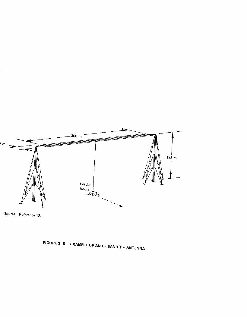
",
Sour@: Reference 12.

(a) Plan View
f = 15.5 kHz h = 19.3 Km R, = 0.144 ohm X = 63 ohms P, = 1 MW VI = 435 MVA
pf, = .0023
(b) Elevation View
Source: Reference 4.
FIGURE 3-6 EXAMPLE OF STATE-OF-THE-ART LARGE VLF ANTENNA IN NORTHWEST CAPE AUSTRALIA
LI
Arthur D Little, Inc
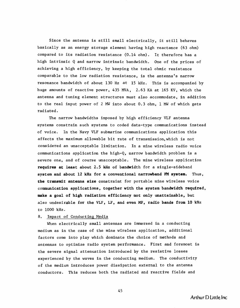
Since t h e antenna i s s t i l l small e l e c t r i c a l l y , i t s t i l l behaves
b a s i c a l l y a s an energy s t o r a g e element having h igh r eac t ance (63 ohm)
compared t o i t s r a d i a t i o n r e s i s t a n c e (0.14 ohm). It t h e r e f o r e has a
high i n t r i n s i c Q and narrow i n t r i n s i c bandwidth. One of t h e p r i c e s of
ach iev ing a h igh e f f i c i e n c y , by keeping t h e t o t a l ohmic r e s i s t a n c e
comparable t o t h e low r a d i a t i o n r e s i s t a n c e , is t h e an tenna ' s narrow
resonance bandwidth of about 130 Hz a t 15 kHz. This i s accompanied by
huge amounts of r e a c t i v e power, 435 MVA, 2.63 KA a t 165 KV, which t h e
antenna and tun ing element s t r u c t u r e s must a l s o accommodate, i n a d d i t i o n
t o t h e r e a l i npu t power of 2 MW i n t o about 0 .3 ohm, 1 MW of which g e t s
r a d i a t e d .
The narrow bandwidths imposed by high e f f i c i e n c y VLF antenna
systems c o n s t r a i n such systems t o coded data- type communications i n s t e a d
of vo ice . I n t h e Navy VLF submarine communications a p p l i c a t i o n t h i s
a f f e c t s t h e maximum a l lowable b i t r a t e of t ransmission,which is no t
considered an unacceptable l i m i t a t i o n . I n a mine wireless r a d i o vo ice
communications a p p l i c a t i o n t h e high-Q, narrow bandwidth problem is a
s e v e r e one, and of course unacceptable . The mine wireless a p p l i c a t i o n
r e q u i r e s a t leaet about 2.5 kHz of bandwidth f o r a s ingle-s ideband
system and about 12 kHz f o r a convent iona l narrowband FM system. Thus,
t h e t r ansmi t antenna s i z e c o n s t r a i n t f o r p o r t a b l e mine w i r e l e s s vo i ce
communication a p p l i c a t i o n s , t o g e t h e r w i t h t h e system bandwidth required,
make a goa l o f h igh r a d i a t i o n e f f i c i e n c y n o t on ly u n a t t a i n a b l e , bu t
a l s o undes i r ab l e f o r t h e VLF, LF, and even MF, r a d i o bands from 10 kHz
t o 1000 kHz.
8. Impact of Conducting Media
When e l e c t r i c a l l y small antennas a r e immersed i n a conduct ing
medium a s i n t h e case of t h e mine w i r e l e s s a p p l i c a t i o n , a d d i t i o n a l
f a c t o r s come i n t o p l ay which dominate t h e choice of methods and
antennas t o opt imize r a d i o system performance. F i r s t and foremost is
t h e s eve re s i g n a l a t t e n u a t i o n in t roduced by t h e r e s i s t i v e l o s s e s
experienced by t h e waves i n t h e conducting medium. The conduc t iv i t y
of t h e medium in t roduces power d i s s i p a t i o n e x t e r n a l t o t h e antenna
conductors . This reduces bo th t h e r a d i a t e d and r e a c t i v e f i e l d s and
Arthur D Little, Inc

powers t h a t would be p r e sen t i n a f r e e space medium, thereby g r e a t l y
reduc ing t h e a t t a i n a b l e communication range. This e f f e c t is w e l l dep i c t ed
i n F igure 2-1 i n t h e preced ing chap t e r . Furthermore, t h e f r e e space
d e f i n i t i o n s of r a d i a t i o n r e s i s t a n c e and r a d i a t e d power a r e no longer
meaningful measures of performance o r antenna e f f i c i e n c y . The so-ca l led
r a d i a t e d power is no l onge r a f i x e d va lue independent of d i s t a n c e i n t h e
antenna f a r f i e l d , and t h e r a d i a t i o n r e s i s t a n c e is no l onge r a measure
of t h e i npu t power coupled t o o r consumed by t h e medium e x t e r n a l t o t h e
a n t enna . Limi t a t i ons imposed by s i g n a l a t t e n u a t i o n and r e p r e s e n t a t i v e
mine development p r a c t i c e s have l e d t o t h e r e l a t i v e l y modest range
goal of 1350 f e e t f o r t h e p o r t a b l e , o r mine w i r e l e s s system, a range
which f a l l s w e l l w i t h i n t h e f r e e space n e a r f i e l d reg ion , and by and
l a r g e , w i t h i n t h e i nduc t i on f i e l d reg ion i n a c o a l mine conduct ing
medium. Consequently, t h e mine w i r e l e s s cormnunication s i t u a t i o n i s
reduced t o a nea r and i nduc t i on f i e l d coupl ing problem between two
l o o s e l y coupled and mobile e lec t romagnet ic f i e l d t r ansduce r s (antennas)
embedded i n a l o s s y medium. Thus, t h e choice of antenna f o r t h e
p o r t a b l e mine w i r e l e s s a p p l i c a t i o n w i l l no t be based on i t s r a d i a t i o n
e f f i c i e n c y , b u t on:
t h e o v e r a l l power u t i l i z a t i o n e f f i c i e n c y of t h e t r a n s m i t t e r -
antenna system i n producing t h e l a r g e s t u sab l e s i g n a l s t r e n g t h
a t t h e d e s i r e d range , and
a t h e o v e r a l l p r a c t i c a l i t y of i t s implementation w i t h regard t o
o v e r a l l system s i z e , weight , convenience, and mine wor th iness
f o r t h e rov ing miner a p p l i c a t i o n .
Before proceeding t o t h e d i s cus s ion of s p e c i f i c antenna types i n
t h e fo l lowing s e c t i o n , we compare t h e behavior of t h e rece ived s i g n a l s
produced by t h e p r i n c i p a l f i e l d components of e l e c t r i c a l l y smal l loop
and d i p o l e t r a n s m i t antennas embedded i n a conduct ing medium. The
p o r t a b l e antennas r e t a i n t h e i r e l e c t r i c a l l y sma l l c l a s s i f i c a t i o n because
t h e reduced wavelength (def ined a s X = 2rx s k i n depth i n t h e conduct ing
medium) remains much g r e a t e r than t h e antenna s i z e f o r t h e f r equenc i e s
and c o n d u c t i v i t i e s of i n t e r e s t . Equat ions f o r t h e Ee and He f i e l d
Arthur D Little, Inc.

components produced by i d e a l i n f i n i t e s i m a l e l e c t r i c and magnetic d i p o l e
sou rce s , r e s p e c t i v e l y , a r e used t o compare t h e loop-to-loop response
w i t h t h e dipole- to-dipole response. The f i e l d component equa t i ons apply
f o r t h e cond i t i on a >> we, which g e n e r a l l y a p p l i e s throughout t h e
f requency band and range of c o n d u c t i v i t i e s o f i n t e r e s t f o r t h e p o r t a b l e
mine wireless a p p l i c a t i o n .
For d i p o l e s : Ee - - - Ih ( 1 + y r + ~ ~ r ~ ) e - ~ ~ s i n e 3
4rrr a
N I A 2 2 - For loops : He = -(1 + y r + y r ) e Yrs ine 4rrr 3
2 2 where y = jwpa-u ep :: jwpa.
The equa t i ons a r e f o r z-axis o r i e n t e d i n f i n i t e s i m a l d i p o l e and loop
antenna elements , ( I 4 ) and I is t h e uniform c u r r e n t i n t h e antenna
elements . The equa t ions apply f o r a loop f u l l y i n s u l a t e d from t h e
medium, and a d i p o l e i n s u l a t e d along i t s l eng th b u t grounded t o t h e
medium a t each end of t h e d ipo l e . h is t h e l e n g t h o f t h e d i p o l e
e lement , A is t h e a r e a of t h e c u r r e n t loop,and N i s t h e number of
t u r n s i n t h e loop.
Taking t h e r a t i o of t h e open c i r c u i t ou tpu t v o l t a g e induced i n
t h e r e c e i v e antenna of each p a i r o f l i k e antennas ( i . e . , d ipo le -d ipo le ,
loop-loop) , w e g e t t h e comparison f a c t o r 3
Voc ( d i p o l e s ) ~~h~ F = -
d , ~ Voc(lOOps) - 2 N I ~ A 2 wpa '
S u b s t i t u t i n g i n t o (11) t h e r e p r e s e n t a t i v e va lues of h = 0.5 m, A = 0.2 m 2
based on a 0.5 m loop d iameter , N = 10 t u r n s , p = po = 4rr x 10-~h/m, -2
conduc t iv i t y a = 10 mho/m, and frequency f = 300 kHz, w e f i n d t h a t
F reduces t o d,R
F d,. =(?) Therefore , i t becomes apparen t t h a t based on t h i s measure of performance
f o r an tennas i n a conduct ing medium, t h e advantage enjoyed by t h e d i p o l e
over t h e loop i n f r e e space does n o t app ly i n a conduct ing medium. A
Arthur D Little Inc.

s i m i l a r conclusion was reached by i n v e s t i g a t o r s ( I 5 ' 1 6 ) a t t h e Univers i ty
of Innsbruck i n Aus t r i a dur ing t h e course of a VLF through-the-earth
communications p r o j e c t funded by t h e U. S. A i r Force. Furthermore,
when t h e d i f f i c u l t y of d r i v i n g t h e antennas t o o b t a i n t h e requi red
c u r r e n t s I and I& is a l s o f ac to red i n t o t h i s comparison equa t ion , d
t h e loop antenna is clearly seen t o b e t h e most favorable ante-.
For example, t h e resonant impedance of a tuned loop having a
bandwidth of 12 kHz a t 300 kHz is about 10 ohms, whereas t h e p r a c t i c a l
grounded d i p o l e source is faced wi th t h e spreading r e s i s t a n c e of i t s
two ground connect ions t o t h e medium. These two connect ions can
t a k e on va lues g r e a t e r than 200 ohms, based on a s imple 0.5 m ground -2
rod te rmina t ion a t each end of t h e d i p o l e i n a medium having a = 10 mho/m.
I f both antennas a r e dr iven by t h e same vo l t age , t h e r e s u l t a n t performance
f a c t o r F i s given by: d,R
S u b s t i t u t i n g t h e above parameter va lues , and t ak ing i n t o account t h e
i n c r e a s e i n t h e e f f e c t i v e l eng th of t h e d i p o l e antenna caused by t h e
i n s u l a t e d ground rod te rmina t ions , we f i n d t h a t F = 0.1. Since t h e d,R
medium conduc t iv i t y a a l s o appears i n t h e numerator of F when Zd is d,R
t h e sp read ing r e s i s t a n c e of ground rods , t h i s performance comparison
should remain i n s e n s i t i v e t o t h e conduc t iv i t y of t h e medium f o r t h e
c o n d u c t i v i t i e s and frequency band of i n t e r e s t . The lower resonant
impedance of t h e loop w i l l a l s o al low b e t t e r r e c e i v e r u t i l i z a t i o n of
t h e induced open c i r c u i t vo l t age . Thus, t h e loop e x h i b i t s a c l e a r
performance advantage over a t y p i c a l grounded-dipole antenna.
The advantage of t h e loop becomes g r e a t e r when compared t o a
whip-type d i p o l e an tenna , (6) which would be t h e p r a c t i c a l choice over
t h e grounded d ipo le f o r a rov ing miner 's p o r t a b l e r a d i o . This whip
would be a completely i n s u l a t e d antenna n o t grounded t o t h e medium a t
each end. The impedance of t h i s antenna worn by a miner s t and ing i n
a t unne l w i l l be a h igh c a p a c i t i v e reac tance i n s t e a d of t h e modest
r e s i s t a n c e of t h e grounded d ipo le . The s p a t i a l coupl ing t o t h e
surrounding medium would a l s o be reduced.
I
Arthur D Little, Inc

Examining t h e impact of the input impedance change, we f ind t h a t
t h e capaci tance represented by t h e s h o r t whip worn on a person is very
low (approximately 10 p f ) , and sub jec t t o l a r g e v a r i a t i o n s (17918) due
t o "stray" capaci tances such a s those introduced by the whip's v a r i a b l e
proximity t o t h e body and mine environment and by t h e l a r g e tuning c o i l s
requi red t o resonate such a small capaci tance a t 300 kHz. This
s i t u a t i o n t y p i c a l l y requi res t h a t a lumped capaci tance much l a r g e r than
t h e antenna capaci tance be placed i n p a r a l l e l wi th t h e antenna, t o
al low t h e use of a p r a c t i c a l l y s i zed tuning inductor a t 300 kHz, and
t o prevent changes i n the resonant frequency caused by v a r i a t i o n s i n
t h e e f f e c t i v e antenna capacitance. This lower reactance shunt path
w i l l d i v e r t most of t h e tuned c i r c u i t cur rent i n t o t h e l a r g e shunt
capaci tor in s t ead of t h e high reactance antenna. Antenna current
reduct ions of 100 t o 1 a r e not uncommon, thereby p u t t i n g t h e s h o r t
whip-type d ipo le antenna a t a considerable p r a c t i c a l disadvantage f o r
the present roving miner app l i ca t ion . The following sec t ions of t h i s
chapter d iscuss t h e f e a s i b i l i t y and p o t e n t i a l u t i l i t y of s p e c i f i c
antenna types . C. PORTABLE MANPACK ANTENNAS
1. Conventional Whip Antennas
The ob jec t ive f o r the por t ab le mine wi re l e s s app l i ca t ion is t o
ob ta in an antenna t h a t is not only e f f e c t i v e but small , rugged, and
convenient f o r a miner t o wear. E l e c t r i c d ipoles o r whip antennas f a i l
tomeet t h i s ob jec t ive i n a l l r e spec t s a t t h e des i r ed opera t ing f re-
quencies i n t h e mine environment. Therefore, only a b r i e f review of
some of t h e major shortcomings is given below.
The s i z e , convenience, and ruggedness problem can be apprec ia ted
by comparison with HF ba.nd manpack hardware used f o r t a c t i c a l radio
comunica t ions by t h e m i l i t a r y , a user which genera l ly at tempts t o
optimize t h e same c h a r a c t e r i s t i c s of concern t o a mine wi re l e s s
app l i ca t ion . A case i n poin t is the PRC-74 t r ansce ive r which r equ i re s
a 6-foot, induct ive ly loaded whip t o achieve reasonable performance on
t h e s u r f a c e over most of t h e HF band. (9) However, t h e performance of
even such whips, with induct ive loading optimally placed about 0.4 of
Arthur D Little Inc.

t h e way up t h e whip, f a l l s o f f r a p i d l y below about 6 MHz when t h e whip
becomes l e s s than 0.05 A. ( l o ) A semi-f l e x i b l e whip s t r u c t u r e of t h i s
type and l eng th is t o t a l l y incompat i b l e w i th underground roving miner
mine w i r e l e s s a p p l i c a t i o n s . The m i l i t a r y a l s o cons iders i t h igh ly
inconvenien t , p a r t i c u l a r l y s o i n j ung le s , bu t t o l e r a t e s it because of
t h e p r a c t i c a l n e c e s s i t i e s of t a c t i c a l m i l i t a r y communications on t h e
s u r f a c e . The magnitude of t h e problem of course becomes much more
s e v e r e a t f requenc ies i n t h e MF and lower bands o f i n t e r e s t f o r mine
w i r e l e s s r a d i o , p a r t i c u l a r l y when a miner is l i k e l y t o cons ider even
a 25 cm whip unreasonable.
Whip e f f e c t i v e n e s s w i th r e spec t t o s i g n a l s t r e n g t h produced i n a
conduct ing medium and t h e ease of genera t ing such a s i g n a l from a
p r a c t i c a l t r a n s m i t t e r is a l s o poor. The previous s e c t i o n of t h i s
chap te r showed t h a t i d e a l loop antennas a r e more e f f e c t i v e than i d e a l
grounded-dipole antennas i n a conducting medium a t t h e ope ra t i ng
f requenc ies of i n t e r e s t . The problems and performance a s s o c i a t e d wi th
whips r a p i d l y worsen f o r p o r t a b l e manpack a p p l i c a t i o n s , making loop
antennas t h e c l e a r choice f o r p o r t a b l e mine w i r e l e s s a p p l i c a t i o n s .
As mentioned b r i e f l y i n Sec t ion I I I .B .8 an i d e a l e l e c t r i c a l l y
s m a l l whip of about 1 meter l eng th over a p e r f e c t ground p lane i s
c h a r a c t e r i z e d by a very small capac i tance of approximately 10 p f , (17)
which r e s u l t s i n a very high c a p a c i t i v e reac tance a t f requenc ies i n t h e
100 kHz t o . 1 MHz band. The tun ing d i f f i c u l t i e s imposed by t h i s whip
antenna, even i n such a s imple environment, become apparent by looking
a t t h e experience a t HF wi th 6-foot whips; namely, they a r e n e a r l y
imposs ib le t o r e sona t e w i th a p r a c t i c a l series lumped induc tor below
6 MHz because of t h e whip 's high c a p a c i t i v e reac tance . ( I 7 ) For
example, a 10 mh induc tor is r equ i r ed t o r e sona t e a 10 pf c a p a c i t o r a t
300 kHz. The problems worsen when such a whip must be worn on t h e body
of a person i n a manpack a p p l i c a t i o n . The whip 's geometry, and i ts
h igh c a p a c i t i v e r eac t ance below low band VHF, make t h e whip 's i npu t
impedance s t r o n g l y a f f e c t e d by t h e whip 's c loseness t o and p o s i t i o n on
a person ' s body, and by t h e person ' s immediate l o c a l environment, h i s
p o s i t i o n w i t h i n i t , and h i s "connection" t o i t v i a h i s f e e t o r o t h e r
p a r t s o f t h e body. (17,18,1.9)
Arthur D Little, Inc

The p r a c t i c a l problems a s s o c i a t e d w i th t u n i n g and d r i v i n g t h e h igh
and widely v a r i a b l e i n p u t impedance of such a n antenna con f igu ra t i on
become i n t o l e r a b l e . Thus, i t becomes d e s i r a b l e , i f n o t neces sa ry , i n
p r a c t i c e t o : e i t h e r set t h e u n i t down away from t h e body and sur rounding
o b j e c t s ; o r i n c o r p o r a t e c i r c u i t e lements t h a t minimize t h e antenna
impedance v a r i a t i o n s s een by t h e t r a n s m i t t e r and r e c e i v e r and a t t h e
same t ime s i m p l i f y t h e t u n i n g c o i l des ign . Only t h e l a t t e r op t ion is
o p e r a t i o n a l l y a l lowable f o r t h e MF mine w i r e l e s s a p p l i c a t i o n . A
t y p i c a l means of accomplishing t h i s l a t t e r o p t i o n is by adding a l a r g e ,
lumped shun t c a p a c i t o r i n p a r a l l e l w i t h t h e whip. Th i s of course
shun t s a l a r g e p o r t i o n of t h e t r a n s m i t t e r ou tpu t c u r r e n t away from t h e
whip, l e ad ing t o t h e correspondingly l a r g e r educ t i on i n o v e r a l l system
e f f e c t i v e n e s s d i s cus sed i n Sec t i on 111. B. 8.
I n summary, problems a s s o c i a t e d w i t h whip antennas f o r u se i n
p o r t a b l e manpack a p p l i c a t i o n s a r e n o t new, nor a r e t hey unique t o t h e
mine w i r e l e s s a p p l i c a t i o n . They have been and cont inue t o be a sou rce
o f cons ide rab l e concern and d i f f i c u l t y a t bo th low band VHF and HF,
w i th t h e problems becoming p a r t i c u l a r l y a c u t e a t t h e low end of t h e HF
band. Thus, i t is n o t . s u r p r i s i n g t h a t convent iona l whip an tennas are
incompat ib le w i t h t h e MF band mine w i r e l e s s r a d i o a p p l i c a t i o n .
2. Act ive Whip Antennas
A moderate amount of a t t e n t i o n h a s been g iven s i n c e t h e mid-1960's
t o i n v e s t i g a t i o n s of t h e p o t e n t i a l advantages of so - ca l l ed a c t i v e
antennas which i n c o r p o r a t e a t r a n s i s t o r i n t o t h e whip antenna s t r u c t u r e
i t s e l f . I n v e s t i g a t i o n s have inc luded t h e frequency range from VLF t o
UHF, and bo th r e c e i v i n g and t r a n s m i t t i n g a p p l i c a t i o n s . (20-29)
Receiving a p p l i c a t i o n s go t most of t h e a t t e n t i o n u n t i l t h e e a r l y 1970 's
when e f f o r t devoted t o t r a n s m i t a p p l i c a t i o n s was i nc r ea sed . (20,21,22,23,24)
The i n t e n t o f t h i s s e c t i o n is n o t t o p r e sen t a d e t a i l e d exp l ana t i on and
assessment of t h i s work, b u t t o b r i e f l y d e s c r i b e and comment on an
a c t i v e t r a n s m i t t i n g c o n f i g u r a t i o n t h a t ha s been r e p o r t e d (20,21) to
o f f e r c e r t a i n performance advantages over t h a t of a convent iona l series-
tuned whip antenna i n t h e MF band. Our conc lus ion is t h a t t h i s a c t i v e
antenna con f igu ra t i on does n o t overcome t h e cons ide rab l e d i sadvantages
Arthur D Little, Inc.
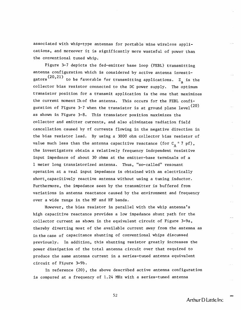
a s s o c i a t e d w i th whip-type antennas f o r p o r t a b l e mine w i r e l e s s app l i -
c a t i o n s , and moreover i t Is s i g n i f i c a n t l y more was t e fu l o f power t han
t h e convent iona l tuned whip.
F igure 3-7 d e p i c t s t h e fed-emi t te r base loop (FEBL) t r a n s m i t t i n g
antenna c o n f i g u r a t i o n which is considered by a c t i v e antenna i n v e s t i -
g a t o r s (20'21) t o be f avo rab l e f o r t r a n s m i t t i n g a p p l i c a t i o n s . Z is t h e S
c o l l e c t o r b i a s r e s i s t o r connected t o t h e DC power supply. The optimum
t r a n s i s t o r p o s i t i o n f o r a t r ansmi t a p p l i c a t i o n i s t h e one t h a t maximizes
t h e c u r r e n t moment I h o f t h e antenna. This occurs f o r t h e FEBL conf i -
gu ra t i on of F igu re 3-7 when t h e t r a n s i s t o r i s a t ground p lane l e v e l (20)
a s shown i n F igure 3-8. This t r a n s i s t o r p o s i t i o n maximizes t h e
c o l l e c t o r and e m i t t e r c u r r e n t s , and a l s o e l i m i n a t e s r a d i a t i o n f i e l d
c a n c e l l a t i o n caused by r f c u r r e n t s f lowing i n t h e nega t i ve d i r e c t i o n i n
t h e b i a s r e s i s t o r l e ad . By us ing a 3000 ohm c o l l e c t o r b i a s r e s i s t o r of
va lue much l e s s than t h e an tenna c a p a c i t i v e r eac t ance ( f o r C " 7 p f ) , A t h e i n v e s t i g a t o r s o b t a i n a r e l a t i v e l y frequency independent r e s i s t i v e
i npu t impedance of about 30 ohms a t t h e emi t te r -base t e rmina l s of a
1 meter long t r a n s i s t o r i z e d antenna. Thus, "so-called" resonant
ope ra t i on a t a r e a l i n p u t impedance is ob ta ined w i t h an e l e c t r i c a l l y
s h o r t , c a p a c i t i v e l y r e a c t i v e an tenna wi thout u s ing a t un ing i nduc to r .
Furthermore, t h e impedance s een by t h e t r a n s m i t t e r i s bu f f e r ed from
v a r i a t i o n s i n antenna r eac t ance caused by t h e environment and frequency
over a wide range i n t h e MF and HF bands.
However, t h e b i a s r e s i s t o r i n p a r a l l e l w i th t h e whip an tenna ' s
h igh c a p a c i t i v e r eac t ance prov ides a low impedance shunt pa th f o r t h e
c o l l e c t o r c u r r e n t a s shown i n t h e equ iva l en t c i r c u i t of F igure 3-9a,
thereby d i v e r t i n g most of t h e a v a i l a b l e c u r r e n t away from t h e antenna a s
i n t h e case of capac i tance shun t ing of convent iona l whips d i scussed
p rev ious ly . I n a d d i t i o n , t h i s shun t ing r e s i s t o r g r e a t l y i n c r e a s e s t h e
power d i s s i p a t i o n of t h e t o t a l antenna c i r c u i t over t h a t r equ i r ed t o
produce t h e same antenna c u r r e n t i n a s e r i e s - t uned antenna equ iva l en t
c i r c u i t of F igure 3-9b.
I n r e f e r e n c e (20 ) , t h e above descr ibed a c t i v e antenna con f igu ra t i on
is compared a t a frequency of 1.24 MHz with a s e r i e s - t uned antenna
I t
Arthur D Little, Inc

Source: Reference 20.
FIGURE 3-7 ACTIVE TRANSMIT ANTENNA FEBL CONFIGURATION
Source: Reference 20.
FIGURE 3-8 FEBL CONFIGURATION FOR MAXIMIZING ANTENNA CURRENT MOMENT
(a) Equivalent Circuit For FEBL Transmit Configuration Of Figure 3-8
w -
(b) Equivalent Circuit For Series Tuned Conventional Whip
Source: Arthur D. Little, Inc.
FIGURE 3-9 EQUIVALENT CIRCUITS
Arthur D Little Inc.

c i r c u i t hav ing a Q o f about 120 (10 kHz bandwidth). By n e g l e c t i n g t h e
power d i s s i p a t e d i n t h e b i a s r e s i s t o r , t h e a c t i v e an tenna i s shown t o
e x h i b i t a "so-cal led" power ga in disadvantage o f about 9 dB compared t o
t h e tuned antenna c i r c u i t . I f account is a l s o taken of t h e power
d i s s i p a t e d i n t h e b i a s r e s i s t o r , t h i s disadvantage i n c r e a s e s cons iderab ly
t o about 27 dB; namely, t h e a c t i v e whip antenna d i s s i p a t e s a t l e a s t
27 dB more power than an equ iva l en t s e r i e s - t uned whip antenna.
F i n a l l y , t h e antenna c u r r e n t va lue s ob ta ined from t h e a c t i v e
an tenna c o n f i g u r a t i o n examined i n r e f e r ence (20) a r e c h a r a c t e r i s t i c of
t h e l e v e l s o b t a i n a b l e from a 12 v o l t b a t t e r y s u i t a b l e f o r a miner 's
p o r t a b l e r ad io . These v a l u e s of 0.4 ma a t 1 .2 MHz and 0 . 1 ma a t 300 kHz
a r e c l e a r l y inadequa te , excep t perhaps f o r extremely s h o r t range, near-
f i e l d a p p l i c a t i o n s i n f r e e space . Thus, a l though a c t i v e antennas may
o f f e r c e r t a i n performance advantages over convent iona l whips i n some
a p p l i c a t i o n s , they o f f e r no p r a c t i c a l b e n e f i t s a s t r ansmi t antennas f o r
MF p o r t a b l e mine w i r e l e s s r ad io s .
3. Conventional Loop Antennas
Conventional a i r - co re loop antennas r e p r e s e n t one of t h e most s u i t a b l e
and e f f e c t i v e cho i ce s f o r t h e MF mine wireless rov ing miner a p p l i c a t i o n .
Thus, i t is n o t s u r p r i s i n g t h a t t h e South Afr icans (30931) and t h e
B r i t i s h (32,33,34 &5) have adopted t h e u s e of such an tennas f o r r e scue
type , p o r t a b l e MF band communications i n mining and f i r e f i g h t i n g a p p l i -
c a t i o n s r e s p e c t i v e l y . S imi l a r developments a r e a l s o occur r ing w i t h i n
t h e U. S. c o a l mining community. (36,37,38,39,40) However, t h e s t a t e -
o f - the-a r t is such t h a t , even w i th such l oops , a completely w i r e l e s s
range goa l of 1350 f e e t i n c o a l mines i s l i k e l y t o be a t t a i n a b l e only
i n t h e most f avo rab l e mine environments (41y42943) ( s ee Chapter 11). On
t h e o t h e r hand, ranges on t h e o r d e r of 1 - 3 km have been r epo r t ed (30,
31935936y40944945)when such loop antennas a r e employed i n t h e v i c i n i t y
of mine e l e c t r i c a l conductors ( s e e Chapter I V f o r r e p r e s e n t a t i v e c a l -
c u l a t i o n s ) . The convent iona l loop antenna has a l a r g e number of p o s i t i v e
a t t r i b u t e s f o r rov ing miner a p p l i c a t i o n s . A t t h e low f r equenc i e s of
i n t e r e s t i t is an i n d u c t i v e l y r e a c t i v e dev i ce whose magnetic f i e l d s
I
Arthur D Little, Inc

and inpu t impedance remain, f o r a l l p r a c t i c a l purposes, unaf fec ted by
i t s l o c a t i o n on and c lo senes s t o t h e body of a person, and a l s o by t h e
l o c a l mine environment. The s t r a y capac i tance problems a s soc i a t ed wi th
whip antennas a r e avoided. The moderate i nduc t ive r eac t ance of a t y p i c a l
loop con f igu ra t i on , having on t h e o rde r of 10 t u r n s , can be e a s i l y
tuned by r e a d i l y a v a i l a b l e p r a c t i c a l c a p a c i t o r s i n t h e MF band. The
loop can be r e a d i l y formed i n t o a l i gh twe igh t , r i g i d o r f l e x i b l e ,
bando l i e r shape. This a l lows t h e a r e a of t h e loop, and t h e r e f o r e t h e
t r ansmi t magnetic moment, t o be maximized w i t h i n a form f a c t o r t h a t can
be t a i l o r e d t o p r o t e c t t h e loop from damage wh i l e provid ing t h e l e a s t
inconvenience t o t h e miner wearing it. Some examples of c u r r e n t des igns
a r e presen ted below.
Rigid u n i t s l i k e t h e t u b u l a r e l l i p t i c a l l y shaped bando l i e r s
dep ic ted i n F igure 3-10aare used wi th t h e South Afr ican r a d i o (30) (SAR)
a t 335 kHz and t h e Co l l i n s Radio mine w i r e l e s s r a d i o pro to types (37) at
520 kHz. They provide t h e advantage of a f i x e d a r e a , and t h e r e f o r e
f i xed t r ansmi t moment and loop i n d u c t a n c e , b u t t h e disadvantage of some-
what g r e a t e r awkwardness than f l e x i b l e bando l i e r conf i g u r a t i o n s . Rep-
r e s e n t a t i v e f l e x i b l e u n i t s inc lude : t h e s t r ap - type depic ted i n F igure
3-lob used by P l e s sey i n i t s Inductor fone TGR.1 u n i t (35) a t 140 kHz and
by Lee Engineering Div is ion of Consol idat ion Coal Co. i n pro to type
u n i t s (36) a t 425 kHz, and garment-type depic ted i n F igure 3-10c where
t h e t u r n s ( t y p i c a l l y s t r anded wire) a r e sewn i n t h e des i r ed shape i n t o
t h e person ' s work uniform o r i n t o a s p e c i a l l y designed j acke t o r pu l l -
over worn by t h e radio-equipped person. For example, t h e P l e s sey
#PRD2200 u n i t used by f i r e f i g h t e r s i n l a r g e bu i ld ings a t 2.5 t o 3.5 MHz
is incorpora ted i n t o a s p e c i a l j e r k i n , (33) whereas one of t h e Lee
Engineering pro to type u n i t s (36) a t 425 kHz has t h e loop sewn i n t o a
p a i r of miner 's c o v e r a l l s approximately a s shown i n F igure 3-10c. The
Rus s i a n s (45) have a l s o made use of loop an tennas , i n a hand-carried
con f igu ra t i on , f o r mine r a d i o communications a t 78 kHz. The loop
o r i e n t a t i o n which r e s u l t s from wearing a bando l i e r type of antenna
( i . e . , i n a n e a r l y v e r t i c a l p lane) a l s o c l o s e l y approximates t h e i d e a l
o r i e n t a t i o n f o r coupl ing t o t h e quasi-TEM mode of propagat ion i n t h e
Arthur D Little Inc

a.
Rig
id O
val T
ubul
ar T
ype
b.
Flex
ible
Str
ap T
ype
C.
Gar
men
t Typ
e
Sou
rce:
R
efer
ence
s 30
, 35
, 36,
37
and
Art
hur
D.
Litt
le,
Inc.
FIG
UR
E 3
-1 0
S
KE
TCH
ES
OF
SE
VE
RA
L B
AN
DO
LIE
R L
OO
P A
NT
EN
NA
CO
NF
IGU
RA
TIO
NS
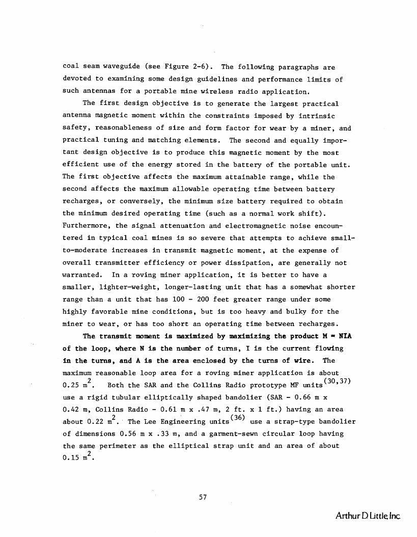
coa l seam waveguide (see Figure 2-6). The following paragraphs a r e
devoted t o examining some design guidel ines and performance l i m i t s of
such antennas f o r a po r t ab le mine wi re l e s s r ad io app l i ca t ion .
The f i r s t design ob jec t ive is t o generate t h e l a r g e s t p r a c t i c a l
antenna magnetic moment wi th in t h e c o n s t r a i n t s imposed by i n t r i n s i c
s a f e t y , reasonableness of s i z e and form f a c t o r f o r wear by a miner, and
p r a c t i c a l tuning and matching elements. The second and equally impor-
t a n t design ob jec t ive is t o produce t h i s magnetic moment by the most
e f f i c i e n t use of t h e energy s to red i n t h e b a t t e r y of t h e por t ab le un i t .
The f i r s t ob jec t ive a f f e c t s t h e maximum a t t a i n a b l e range, while t h e
second a f f e c t s t h e maximum allowable opera t ing time between b a t t e r y
recharges, o r conversely, t h e minimum s i z e b a t t e r y requi red t o ob ta in
t h e minimum des i red opera t ing time (such a s a normal work s h i f t ) .
Furthermore, t h e s i g n a l a t t e n u a t i o n and electromagnetic no i se encoun-
t e r e d i n t y p i c a l coal mines is s o severe t h a t at tempts t o achieve small-
to-moderate increases i n t ransmi t magnetic moment, a t t h e expense of
o v e r a l l t r a n s m i t t e r e f f i c i ency o r power d i s s i p a t i o n , a r e genera l ly not
warranted. I n a roving miner app l i ca t ion , i t is b e t t e r t o have a
sma l l e r , l ighter-weight , longer- las t ing un i t t h a t has a somewhat s h o r t e r
range than a u n i t t h a t has 100 - 200 f e e t g r e a t e r range under some
highly favorable mine condi t ions , but is too heavy and bulky f o r t h e
miner t o wear, o r has too s h o r t an opera t ing time between recharges.
The t ransmi t moment is maximized by maximizing t h e product M = NfA
of t h e loop, where N is t h e number of tu rns , 1 is t h e current flowing
i n t h e tu rns , and A is t h e a r e a enclosed by t h e t u r n s of wire. The
maximum reasonable loop a rea f o r a roving miner app l i ca t ion is about 2
0.25 m . Both t h e SAR and t h e Col l ins Radio prototype MF u n i t s (30,371
use a r i g i d tubu la r e l l i p t i c a l l y shaped bandolier (SAR - 0.66 m x
0.42 m, Col l ins Radio - 0.61 m x .47 m, 2 f t . x 1 f t . ) having an a r e a 2
about 0.22 m . The Lee Engineering uni t s (36) use a s trap-type bandol ier
of dimensions 0.56 m x .33 m, and a garment-sewn c i r c u l a r loop having
t h e same perimeter a s the e l l i p t i c a l s t r a p u n i t and an a rea of about 2
0.15 m .
Arthur D Little Inc

A p r a c t i c a l number of tu rns appears t o be i n t h e 5 t o 15 t u r n range
(SAR and Col l ins - 7 tu rns , Lee Engineering - 12 tu rns ) . The inductance
of an a i r c o r e loop having a diameter d and a s i n g l e l a y e r winding of
width w is given by t h e equation
L M ~ ' ~ N ~ microhenries (14)
from Watt,@) where A is t h e loop a rea i n square meters, N i s t h e
number of t u r n s , and k i s t h e inductance form f a c t o r which depends on
t h e r a t i o of d/w. k is a slowly changing funct ion f o r t h e d/w range of
present i n t e r e s t , varying from a value of about 1 .8 f o r d/w = 5 t o a value 2
of about 3.6 f o r d/w = 50. Thus, a loop having an a r e a A = 0.25 m , 10 tu rns , and an e f f e c t i v e d/w r a t i o of about 25 (k = 3) r e s u l t s i n an
inductance of about 150 ph, which can be e a s i l y ser ies- tuned with prac-
t i c a l capac i to r values on t h e order of 1000 pf i n t h e 300 - 500 kHz
frequency band. Reducing t h e turns t o 7 gives about 75 ph, which is
c lose t o t h e measured va lues of 60 ph and 82 ph f o r t h e SAR and Col l ins
loop antennas, respect ive ly . Thus, t he capaci tor values required f o r
tuning increase accordingly t o between 1000 pf and 5000 p f , depending on
t h e inductance value and opera t ing frequency.
A bandwidth of 1 2 kHz i n t h e 300 t o 500 kHz band requi res a Q of 2 25 t o 42 respect ive ly . For a series- tuned 8-turn, 0.25 m , loop of
nominal 100 ph inductance, t h i s means a r e a l impedance l e v e l of 7.5 ohms
a t t h e resonant opera t ing frequency. Thus, an rms loop current on t h e
order of 1 ampere is obta inable from a t r ansmi t t e r opera t ing from a 12
v o l t b a t t e r y supply. A double totem pole , c l a s s D , t r a n s i s t o r bridge
output s t a g e is one example of a highly e f f i c i e n t way t o u t i l i z e t h e
f u l l b a t t e r y vol tage on both p o s i t i v e and negat ive h a l f cycles . This
allows t h e generat ion of a p r a c t i c a l r m s t ransmi t moment, M = N I A , of 2
about 2 amp-m , a value near ly equal t o t h a t of t h e Co l l ins Radio
prototype u n i t , and s l i g h t l y h igher than t h e moment of t h e SAR un i t .
The i n t r i n s i c s a f e t y curve shown i n Figure 3-11 (46,47,48) is
based on t h e f indings of t h e Mining Enforcement and Safe ty Administration
(MESA) f o r DC induct ive c i r c u i t s . It revea l s t h a t f o r an inductance
of 100 ph t h e rms cur ren t of 1 ampere is already c lose t o t h e band
lli
Arthur D Little. Inc

100 ma 1 a Current
Source: Ref. 46.
FlGURE 3-11 MINIMUM IGNITING CURRENT AS A FUNCTION OF '
AN INDUCTIVE CIRCUIT FOR AN 8.3% METHANEIAIR MIXTURE
Arthur D Little Inc

def in ing t h e zone of maximum s a f e cu r ren t l e v e l . In AC app l i ca t ions ,
t h i s l e v e l must represent t h e peak current (48) l e v e l , s o t h e 1 amp rms
l e v e l compared t o t h e allowed 2 amps peak includes a modest s a f e t y
f a c t o r . It can be seen from t h e p l o t t h a t s i g n i f i c a n t gains i n t ransmi t
moment cannot be obtained from inc reases i n cur rent a t t h i s inductance.
Nor can they be obtained by increas ing t h e number of t u r n s , s i n c e t h e
inductance, and a l s o t h e r e s i s t a n c e f o r a f ixed bandwidth requirement, 2
inc reases more r ap id ly ( a s N ) than t h e moment ( a s N), thereby reducing
t h e maximum a t t a i n a b l e and i n t r i n s i c a l l y s a f e cu r ren t .
In t h e o the r d i r e c t i o n , namely reducing t u r n s , t h e cu r ren t a t
resonance w i l l i nc rease a s t h e inductance and t h e r e f o r e t h e r e s i s t a n c e
decrease. To avoid problems wi th s t r a y c i r c u i t and cab l ing inductance,
t h e loop inductance should be kept above about 10 ph. This allows a
3 t o 1 reduct ion i n t u r n s , a 9 t o 1 reduct ion i n L and R, a correspond-
i n g 9 t o 1 inc rease i n I, and a n e t increase of 3 t o 1 i n magnetic
moment M. However, even t h i s modest increase i n M i s unrea l i zab le i n
p r a c t i c e . The i n t r i n s i c s a f e t y curve becomes increas ingly s t eep below
1 mh and p a r t i c u l a r l y below 100 ph, (46 948) thereby allowing a t most
perhaps a 1 .5 t o 1 inc rease i n cu r ren t , which r e s u l t s i n a n e t decrease
i n M i n s t e a d of an increase . The p r a c t i c a l l y achievable moment f o r a
7-turn loop having an inductance of about 75 ph, l i k e t h e SAR and
Col l ins loops, w i l l be about t h e same a s t h a t fo r t h e 8-turn, 100 uh
loop, and t h e 1 amp r m s i n t h e 7.5 ohm load w i l l d i s s i p a t e 7.5 watts. The r f vo l t age ac ross the tun ing capac i to r (and t h e loop inductor )
a t an ope ra t ing frequency of 500 kHz w i l l be a s high a s 318 v o l t s r m s
(450 V-peak) f o r a 1000 pf capaci tor ca r ry ing a cu r ren t of 1 amp rms.
These vol tages f a l l w e l l w i th in t h e s a f e a r e a of t h e i n t r i n s i c s a f e t y
p l o t f o r capac i to r s (46) shown i n Figure 3-12.
It should a l s o be r e a l i z e d t h a t e x i s t i n g i n t r i n s i c s a f e t y curves
a r e based on DC c i r c u i t experience. The sub jec t becomes much more
complex (48) f o r AC a p p l i c a t i o n s , s o t h e DC-based curves se rve only a s
approximate design guide l ines f o r t h e MF band radio app l i ca t ion . In
t h e end, v e r i f i c a t i o n of t h e MF mine wi re l e s s po r t ab le r ad io ' s i n t r i n -
s i c s a f e t y w i l l be determined only a f t e r t h e r ad io , inc luding t h e
Arthur D Little Int
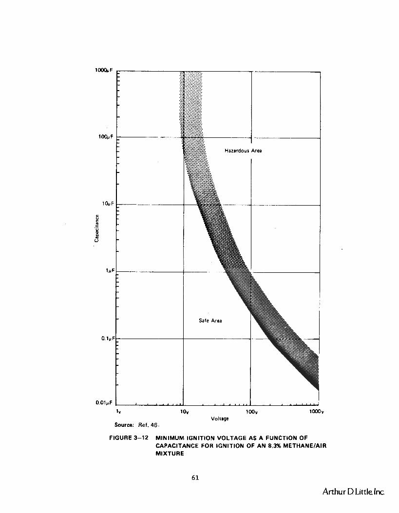
FIGURE 3-12 MINIMUM IGNITION VOLTAGE AS A FUNCTION OF CAPACITANCE FOR IGNITION OF AN 8.3% METHANEIAIR MIXTURE
Arthur D Little Inc
antenna, has success fu l ly completed methane i g n i t i o n t e s t s conducted by
MESA i n i t s s p e c i a l t e s t f a c i l i t y .
The above d iscuss ion shows t h a t p r a c t i c a l values of magnetic
moment M f o r a po r t ab le MF band u n i t a r e not l i k e l y t o exceed t h e values 2 of about 2.5 amp-m peak a v a i l a b l e with present prototype equipment.
This represents only a 12 dB improvement i n s i g n a l l e v e l s over those
obtained i n t h e performance es t imates of Chapter I1 f o r a moment of 2
0.7 amp-m . I n h ighly favorable mine a t t enua t ion and noise environments,
t h i s may r e s u l t i n a range increase of about 300 f t . over t h a t predic ted
i n Table 2-1 of Chapter 11. I n fair-to-poor mine environments, range
increases of l e s s than 50 f t . w i l l occur and t h e completely-wireless
communication range w i l l remain hopelessly small i n these s i t u a t i o n s
a s shown i n Chapter I1 and reference (41).
The major ob jec t ive f o r MF mine wi re l e s s radios should the re fo re be
t o ob ta in t h e most reasonable value of magnetic moment cons i s t en t with
a t ransmi t te r /antenna c i r c u i t design t h a t provides t h e most e f f i c i e n t
use of t h e b a t t e r y ' s energy supply. This w i l l l ead t o a po r t ab le
system wi th t h e smal les t b a t t e r y s i z e , and the re fo re smal les t po r t ab le
u n i t s i z e and weight, f o r s a t i s f y i n g t h e p r i n c i p a l opera t ional require-
ments, of which t h e wearab i l i ty and opera t ing l i f e t i m e between charges
a r e a s important, i f not more so , than t h e magnitude of t h e t ransmit
magnetic moment. This suggests t h e use of MF t r ansmi t t e r s designed t o
ope ra te i n a la rge-s ignal mode (such a s t h e one mentioned above) t o
obta in e f f i c i e n c y b e n e f i t s s i m i l a r t o those of switching-type t rans-
m i t t e r s a t lower frequencies, and optimized f o r d r iv ing a por table
u n i t antenna having a r e l a t i v e l y low tuned impedance a t t h e opera t ing
frequency.
I n summary, a i r -core , bandolier-type loops provide a f e a s i b l e , p r a c t i c a l s o l u t i o n t o the MI? wire le s s radio antenna problem, but a t a
p r i c e of minor-to-moderate inconvenience t o t h e miner, depending on
whether t h e antenna i s sewn i n t o a garment o r fashioned i n t o a f l e x i b l e
o r r i g i d bandolier . The most s u i t a b l e and p r a c t i c a l conf igura t ion f o r
a p a r t i c u l a r mine app l i ca t ion is bes t determined by in-mine t r i a l s
with prototype designs. The convenience of wear of fered by t h e garment
Arthur D Little, Inc
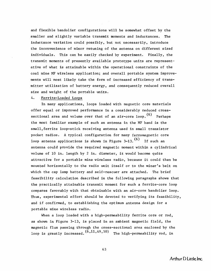
and f l e x i b l e bando l i e r con f igu ra t i ons w i l l be somewhat o f f s e t by t h e
smaller and s l i g h t l y v a r i a b l e t r a n s m i t moments and induc tances . The
induc tance v a r i a t i o n could p o s s i b l y , bu t no t n e c e s s a r i l y , i n t roduce
t h e inconvenience o f minor r e t u n i n g o f t h e antenna on d i f f e r e n t s i z e d
i n d i v i d u a l s . This can b e e a s i l y checked by experiment. F i n a l l y , t h e
t r ansmi t moments of p r e s e n t l y a v a i l a b l e p ro to type u n i t s a r e r ep re sen t -
a t i v e of what is a t t a i n a b l e w i t h i n t h e o p e r a t i o n a l c o n s t r a i n t s of t h e
c o a l mine MF wireless a p p l i c a t i o n ; and o v e r a l l p o r t a b l e system improve-
ments w i l l most l i k e l y t a k e t h e form of i nc r ea sed e f f i c i e n c y of t r ans -
mitter u t i l i z a t i o n of b a t t e r y energy, and consequent ly reduced o v e r a l l
s i z e and weight of t h e p o r t a b l e u n i t s .
4. Ferr i te-Loaded Loops
I n many a p p l i c a t i o n s , loops loaded w i th magnetic co re m a t e r i a l s
o f f e r equa l o r improved performance i n a cons iderab ly reduced c ross -
s e c t i o n a l a r e a and volume ove r t h a t of an a i r - c o r e loop . (6) Perhaps
t h e most f a m i l i a r example of such a n antenna i n t h e MF band is t h e
s m a l 1 , f e r r i t e l oop - s t i ck r e c e i v i n g antenna used i n small t r a n s i s t o r
pocket r a d i o s . A t y p i c a l con f igu ra t i on f o r many fe r romagnet ic c o r e
loop antenna a p p l i c a t i o n s is shown i n F igure 3-13. (6 ) I£ such an
an tenna could prov ide t h e r equ i r ed magnetic moment w i t h i n a c y l i n d r i c a l
volume of 10 i n . l e n g t h by 2 i n . d iameter , i t would become q u i t e
a t t r a c t i v e f o r a p o r t a b l e mine wireless r a d i o , because i t could t hen be
mounted h o r i z o n t a l l y t o t h e r a d i o u n i t i t s e l f o r t o t h e mine r ' s b e l t on
which t h e cap lamp b a t t e r y and s e l f - r e s c u e r a r e a t t a ched . The b r i e f
f e a s i b i l i t y c a l c u l a t i o n descr ibed i n t h e fo l lowing paragraphs shows t h a t
t h e p r a c t i c a l l y a t t a i n a b l e t r ansmi t moment f o r such a f e r r i t e - c o r e loop
compares f avo rab ly w i t h t h a t o b t a i n a b l e w i t h an a i r - c o r e bando l i e r loop.
Thus, exper imental e f f o r t should be devoted t o v e r i f y i n g i t s f e a s i b i l i t y ,
and i f confirmed, t o e s t a b l i s h i n g t h e optimum antenna des ign f o r a
p o r t a b l e mine w i r e l e s s r ad io .
When a loop loaded w i t h a high-permeabi l i ty f e r r i t e c o r e o r r od ,
a s shown i n F igure 3-13, is p laced i n a n ambient magnetic f i e l d , t h e
magnetic f l u x pa s s ing through t h e c ro s s - s ec t i ona l a r e a enc losed by t h e
loop is g r e a t l y increased . (6 911949 350) The high-permeabi l i ty rod , i n
Arthur D Little Inc
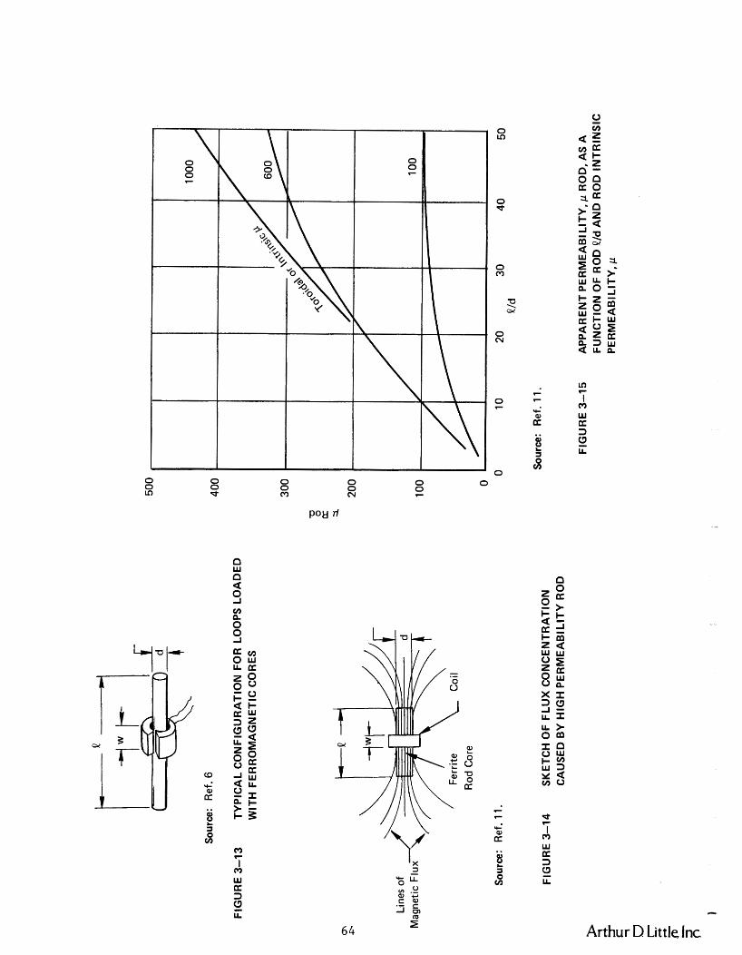
Sou
rce:
R
ef. 6
FIG
UR
E 3
-13
TY
PIC
AL
CO
NF
IGU
RA
TIO
N F
OR
LO
OP
S L
OA
DE
D
WIT
H F
ER
RO
MA
GN
ET
IC C
OR
ES
Ferr
ite
Coi
l R
od C
ore
Sou
rce:
R
ef.
1 1.
Sou
rce:
R
ef.
1 1.
FIG
UR
E 3
-14
SK
ET
CH
OF
FL
UX
CO
NC
EN
TR
AT
ION
C
AU
SE
D B
Y H
IGH
PE
RM
EA
BI L
lTY
RO
D
FIG
UR
E 3
-15
AP
PA
RE
NT
PE
RM
EA
BIL
ITY
, p R
OD
, AS
A
FU
NC
TIO
N O
F R
OD
P/d
AN
D R
OD
INT
RIN
SIC
P
ER
ME
AB
ILIT
Y, p

e f f e c t , ga thers and concentrates t h e magnetic f l u x lines i n t h e v i c i n t y
.of the rod, and causes them t o pass through t h e rod which threads t h e
loop, as depic ted i n Figure 3-14. This g rea t ly increases t h e "captured"
f lux , t h e "e f fec t ive area ," and the re fo re t h e induced open c i r c u i t out-
put vol tage of t h e loop a c t i n g a s a rece ive antenna. The presence of
t h e rod can a l s o be viewed a s inc reas ing t h e e f f e c t i v e permeabil i ty of
the medium surrounding t h e antenna, thereby c r e a t i n g t h e increased f l u x
l inkage and output vol tage of t h e loop. By r e c i p r o c i t y , i t can be shown
t h a t t h e magnitude of t h e f i e l d s generated by such a loop, when a c t i n g
a s a t ransmi t antenna, w i l l be s i m i l a r l y a rod of magnetic
mater ia l . The t ransmi t improvement w i l l
recept ion wi th in t h e l i n e a r opera t ing region of t h e mater ia l . I n prac-
t i c e , s i g n i f i c a n t improvements i n t ransmi t magnetic moment can be rea l -
ized with p r a c t i c a l ma te r i a l s u n t i l t h e ma te r i a l s a r e driven i n t o
s a t u r a t i o n . .
The presence of t h e magnetic rod core causes t h e f l u x l inked and
produced by t h e loop, t h e loop inductance, and t h e loop Q, t o be increased
by d i f f e r e n t amounts. The amount of inc rease depends on t h e shape and
s i z e of t h e rod and on t h e relative permeabil i ty, v , of t h e rod ma te r i a l ,
a l s o r e f e r r e d t o a s t h e i n t r i n s i c permeabil i ty of t h e rod ma te r i a l when
measured i n a t o r o i d (utoroid ) ( l 1 A considerable amount of analy t -
i c a l and experimental work has been done (6 9 11 ,50,51,52,53) to quantitatively
descr ibe how t h e above q u a n t i t i e s depend on t h e i n t r i n s i c permeabil i ty
of t h e rod material, on t h e shape o r R/d r a t i o of t h e rod, and on t h e
length of t h e rod compared t o t h e length of t h e loop o r c o i l , namely
t h e R/W r a t i o .
Refer r ing t o Figure 3-14, t h e b e s t o v e r a l l p r a c t i c a l performance
of f e r r i t e rod antennas genera l ly occurs when & / d 5 20, t / w 8, and
R / D s 4. Furthermore, a s i l l u s t r a t e d i n Figure 3-15, when t h e i n t r i n s i c
permeabil i ty p is g r e a t e r than about 500 t o 600, t h e e f f e c t i v e perme-
a b i l i t y of t h e rod urod becomes e s s e n t i a l l y independent of t h e i n t r i n s i c
This is p a r t i c u l a r l y s o f o r t h e R/d range of p r i n c i p a l i n t e r e s t f o r
t h e MF mine wi re l e s s radio , namely L/d 6 20. Figure 3-15 shows t h e
apparent o r e f f e c t i v e permeabil i ty of the rod, ( inc rease i n
Arthur D Little Inc

rece ived f l u x o r t r ansmi t t ed f i e l d s t r e n g t h f o r t h e loop) a s a func t ion
of length-to-diameter r a t i o , & I d , of c y l i n d r i c a l rods having var ious
i n t r i n s i c o r t o r o i d a l p e r m e a b i l i t i e s , v . The i n c r e a s e i n t h e inductance
of t h e c o i l o r loop caused by t h e rod can b e expressed a s an i n c r e a s e
i n t h e c o i l permeabi l i ty , v c o i l The i n c r e a s e i n vcoil is gene ra l l y
much less than t h e i n c r e a s e i n v-_,, except when t h e &Id r a t i o i s n o t (6,111
LUU
much l a r g e r than u n i t y , and "oi l gene ra l l y i n c r e a s e s w i th t h e
l eng th of t h e c o i l on t h e rod. w.Q of the co i l is also increased by
. the presence of the rod, so the rod material pQ product in the frequency
band of interest is generally an important design parameter. ' A
plot of typical pQ product behavior as a func t ion of frequency below
10 MHz can be found i n reference (51).
To a s s e s s t h e f e a s i b i l i t y of us ing a f e r r i t e rod loop antenna f o r
t h e p o r t a b l e mine wireless MF r a d i o , a rod m a t e r i a l form f a c t o r and
s i z e i s chosen t h a t o f f e r s f avo rab l e performance, i s compact enough t o
be conveniently worn by a miner, and is readily available from suppliers.
A 10 in. long, 1 in. diameter (&/d - 10) rod of manganese-zinc (MnZn)
f e r r i t e material t y p i c a l l y used f o r antenna rods i n t h e LF and MF bands
from about 100 kHz t o 2 MHz is assumed. (54 955) This m a t e r i a l t y p i c a l l y
baa a saturation f lux density B of about 0 .3 tes la and an intrinsic sat i n i t i a l permeability p of 500 to 1000.
The s a t u r a t i o n f l u x dens i ty de f ines t h e maximum moment t h a t a
given volume of t h e m a t e r i a l can produce. This maximum M is given s a t
by
when t h e f l u x d e n s i t y is uniformly d i s t r i b u t e d over t h e volume. B s a t is t h e s a t u r a t i o n f l u x d e n s i t y i n t e s l a s , V is t h e volume of t h e rod
3 -7 i n m , and p = 47~ x 10 h/m. S u b s t i t u t i n g f o r B s a t ' 'rod' and p we
0 0 ) 3
f i n d t h a t t h e maximum a t t a i n a b l e moment f o r t h e rod is M = 31 amp-mL s a t
peak, a va lue g r e a t e r than 10 t i m e s t h e maximum i n t r i n s i c a l l y s a f e
moment ob t a inab le w i th a p r a c t i c a l bando l i e r a i r - co re antenna. However,
a s shown below, i t is n o t p o s s i b l e t o gene ra t e t h i s maximum moment i n
an i n t r i n s i c a l l y s a f e manner o r wi th a p r a c t i c a l 12 v o l t t r a n s m i t t e r .
C*
Arthur D Little Inc.

On t h e o t h e r hand, genera t ing t h e 2.5 amp-m2 (peak) moment ob ta inab le
wi th an a i r - co re bando l i e r does appear t o be f e a s i b l e , thereby o f f e r i n g
t h e system des igner a p o t e n t i a l l y a t t r a c t i v e a l t e r n a t i v e t o t h e a i r -
core b a n d o l i e r loop.
The magnetic moment, M, i n t h e m a t e r i a l ' s l i n e a r reg ion below
s a t u r a t i o n is given by
where N is t h e number of t u r n s i n t h e loop, I is t h e loop c u r r e n t i n 2
amperes, A is t h e a r e a i n m enclosed by t h e loop, and p is taken rod from Figure 3-15. For t h e chosen rod having an i n t r i n s i c p of 500 t o
1000 and L/d of l o , w e f i n d from Figure 3-15 t h a t prod = 100. Thus,
equat ion (16) shows t h a t t o genera te t h e a i r - co re bando l i e r peak moment 2
of 2.5 amp-meter would r e q u i r e an N I product of 49 compared t o t h e N I
product o f 14 r equ i r ed f o r t h e 7-turn a i r -core bando l i e r loop d iscussed
i n t h e previous s e c t i o n . Thus, i f t h e f e r r i t e - loaded loop could b e
dr iven wi th t h e s a m e maximum peak cu r ren t of 1.4 amperes, t h e number of
t u r n s r equ i r ed would be N = 35.
A s ing le - l aye r winding which d i s t r i b u t e s t h e 35 t u r n s over a l eng th
of w = 2 i n . i n t h e c e n t e r of t h e 1 i n . diameter rod is chosen. For a
s o l e n o i d a l c o i l wi th t h i s form f a c t o r s t h e s imple a i r - co re inductance
formula a p p l i e s (56)
2 2 = a microhenries ,
Lo 9a + IOW which then must be m u l t i p l i e d by pcoil (6*11) t o o b t a i n t h e inductance
when it is f e r r i t e loaded.
N is t h e number o f , t u r n s , a is t h e c o i l r a d i u s i n inches, and w is t h e
c o i l l eng th i n inches. The va lue of p c o i l
= 10 is used, based on t h e
f i n d i n g t h a t f o r rods having a n L/d r a t i o of 12, p (52,6)
c o i l ' prod11o* Thus, s u b s t i t u t i n g f o r u c o i l ' a , w, and N i n (17) and (18) g ives a f e r r i t e -
loaded loop inductance of L = 125 ph, a va lue c l o s e t o t h a t ob ta ined
wi th a n 8-turn a i r - co re bando l i e r antenna.
The bandw'idth of 1 2 kffi a t an ope ra t ing frequency of 500 kHz
rcqu2res a Q of 42. To achieve t h i s Q a t 500 kHz, a se r ies - tuned r e a l
Arthur D Little lnc
impedance l e v e l (R = w ~ / ~ ) o f 6 .7 ohms is r e q u i r d. This r e s u l t s i n a
s l i g h t l y lower peak c u r r e n t of about 1 .2 amper s than t h e 1 .4 amperes a assumed above f o r e s t ima t ing t h e number of t u r (N = 35) r equ i r ed t o
produce t h e d e s i r e d magnetic moment of 2.5 amp
Therefore , w e f i n d t h a t t h i s f e r r i t e - l o a d d loop con f igu ra t i on is
nea r ly equ iva l en t t o t h e 8-turn bandol ie r loop con f igu ra t i on of t h e
previous s e c t i o n i n a l l r e s p e c t s , inc lud ing i t l o c a t i o n inductance and
current-wise w i t h r e spec t t o t h e s a f e reg ion oundary on t h e i n t r i n s i c
s a f e t y p l o t o f F igure 3-11. A s i n t h e case of he bandol ie r loop, a
modest decrease i n t h e number of t u r n s a l lows moment t o be opt imized
wi th r e s p e c t t o t h e i n t r i n s i c a l l y s a f e cu r r en t inductance l e v e l s . I n 4 t h i s ca se about 28 t u r n s should provide t h e de i r e d peak moment of 2.5
amp-m2 a t t h e inductance and peak c u r r e n t l e v e s of about 80 ph and
1 .8 amperes r e s p e c t i v e l y . S imi l a r r e s u l t s can a l s o be achieved by
d i s t r i b u t i n g t h e 35 t u r n s over a g r e a t e r l e n g t
The above example a l s o i l l u s t r a t e s t h a t t e maximum achievable P moment M def ined by t h e s a t u r a t i o n f l u x d s i t y B and volume of
s a t ' T s a t t h e f e r r i t e rod, would r e q u i r e c u r r e n t l e v e l s i n excess of those which
a r e i n t r i n s i c a l l y - s a f e and g r e a t e r than t h e 12 v o l t power supply could
supply t o t h e r e a l impedance l e v e l imposed by h e bandwidth requirement.
A s i n t h e ca se of t h e a i r - co re bando l i e r loop , ) t h e maximum i n t r i n s i c a l l y - 2
s a f e moment is cons t ra ined t o be about 2.5 amplm . However, t h e prospec t 2
of ach i ev ing t h e M = 2.5 amp-m performance wi h a much smaller antenna f than t h e bando l i e r loop makes t h e f e r r i t e - l o a d d loop very a t t r a c t i v e I= f o r t h e rov ing miner a p p l i c a t i o n . I n f a c t , example sugges ts t h a t
t h i s moment could be achieved wi th even a volume co re than t h e
one used i n t h e example. The f avo rab l e performance of f e r r i t e loaded
loops as r ece iv ing antennas (6911951) make t h e i r use doubly a t t r a c t i v e .
Therefore , e f f o r t should be d i r e c t e d toward v e r i f y i n g t h i s p r ed i c t ed
performance. This is b e s t accomplished e ~ p e r i m e n t a l l y , a s w i l l t h e fu t -
u r e op t imiza t ion of any p r a c t i c a l des ign , should t h e f e a s i b i l i t y be
confirmed.
5 . S p e c i a l Mul t i t u rn Loop (MTL) Antennas
The Ohio S t a t e Univers i ty and o t h e r s have been s tudying and
developing a c l a s s o f e l e c t r i c a l l y small antennas c a l l e d m u l t i t u r n loop (MTL) antennas. (7,57,58,59,60,61,62) The objective has been to
Arthur D Little Inc.
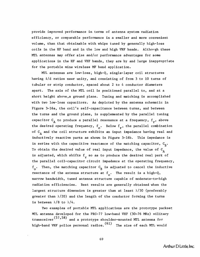
p r ~ v i d e improved performance i n terms of antenna system r a d i a t i o n
e f f i c i e n c y , o r comparable performance i n a sma l l e r and more convenient
volume, than t h a t obta inable with whips tuned by genera l ly high-loss
c o i l s i n t h e HF band and i n t h e low and high VHF bands. Althoilgh these
MTL antennas may o f f e r s i z e and/or performance advantages f o r some
a p p l i c a t i o n s i n t h e HF and VHF bands, they a r e by and l a r g e inappropr i a t e
f o r t h e po r t ab le mine wi re l e s s MF band app l i ca t ion .
MTL antennas a r e low-loss, high-Q, s ingle- layer c o i l s t r u c t u r e s
having ~ / d r a t i o s near un i ty , and c o n s i s t i n g of from 3 t o 10 t u r n s of
t ubu la r o r s t r i p conductor, spaced about 2 t o 4 conductor diameters
a p a r t . The a x i s of t h e MTL c o i l i s pos i t ioned p a r a l l e l t o , and a t a
s h o r t he igh t above,a ground plane. Tuning and matching is accomplished
with two low-loss capac i to r s . A s depicted by t h e antenna schematic i n
Figure 3-16a, t h e c o i l ' s se l f -capaci tance between t u r n s , and between
t h e tu rns and t h e ground plane, is supplemented by t h e p a r a l l e l tun ing
capac i to r C t o produce a p a r a l l e l resonance a t a frequency, A f r , above
t h e des i r ed opera t ing frequency, f . Below f r , t h e p a r a l l e l combination 0
of C and t h e c o i l s t r u c t u r e e x h i b i t s an input impedance having r e a l and A induct ive ly r e a c t i v e p a r t s a s shown i n Figure 3-16b. This impedance is
i n s e r i e s wi th t h e capac i t ive reactance of t he matching capac i to r , CB.
To o b t a i n t h e des i r ed value of r e a l input impedance, t h e value of CA
is ad jus t ed , which s h i f t s f s o a s t o produce t h e des i r ed r e a l p a r t of r t h e p a r a l l e l co i l - capac i to r c i r c u i t impedance a t t h e ope ra t ing frequency,
f . Then, t h e matching capaci tor C is adjus ted t o cancel t h e induct ive 0 B
reac tance of t h e antenna s t r u c t u r e a t f . The r e s u l t is a high-Q, 0
narrow bandwidth, tuned antenna s t r u c t u r e capable of moderate-to-high
r a d i a t i o n e f f i c i e n c i e s . Best r e s u l t s a r e genera l ly obtained when t h e
l a r g e s t s t r u c t u r e dimension i s g r e a t e r than a t l e a s t XI50 (preferably
g r e a t e r than X/20) and t h e length of t h e conductor forming t h e t u r n s
i s between X/8 t o X/4.
Two examples of po r t ab le MTL app l i ca t ions a r e t h e prototype packset
MTL antenna developed f o r t h e PRC-77 low-band VHF (30-76 MHz) m i l i t a r y
t r ansce ive r (57 958) and a pro to type shoulder-mounted MTL antenna f o r
high-band VHF p o l i c e personal r ad ios . (61) The s i z e of each MTL would
Arthur D Little Inc

a. Schematic Diagram of MTL Antenna
b. Impedance Characteristics of MTL Antenna
Source: Reference 7.
FIGURE 3-16 MTL ANTENNA DIAGRAM AND IMPEDANCE CHARACTERISTICS
Y
Arthur D Little Inc.

b e compat ible w i t h a p o r t a b l e mine wireless a p p l i c a t i o n . The low-band
VHF packse t MTL i s a 4-turn squa re c o i l of dimensions 2-1/2 x 2-1/2 x
4-1/2 i nches l ong , mounted t o t h e ba se of t h e PRC-77 r a d i o , and enc losed
i n a f i b e r g l a s p r o t e c t i v e cover which ex tends 5-1/2 i nches below t h e
packse t , which is c a r r i e d a s a backpack by a s o l d i e r . This MTL was
found t o compare favorab ly t o a 3 f t . whip over t h e 30-76 MHz band, b u t
t o a l s o exper ience t u n i n g and p a t t e r n problems a s a r e s u l t of t h e
an t enna ' s high Q and i t s c lo senes s t o t h e body. The h igh band VHF
shoulder-mounted MTL is 2.7 x 2.7 x 0.7 i nches h igh , mounted above a
4.5 x 6.5 i nches shoulder-pad t y p e o f ground p lane . This MTL was found
t o compare favorab ly w i t h a 6 i nch h e l i c a l whip over t h e 150-170 MHz
band, b u t t o a l s o exper ience problems similar t o t h o s e f o r t h e low-band
VHF packse t MTL. Both r equ i r ed t un ing a f t e r be ing mounted on t h e
person , and t h e performance of bo th depended on body p o s i t i o n s and
o r i e n t a t i o n s . A t MF band wavelengths , which a r e between 2 and 3 o r d e r s
of magnitude g r e a t e r than t h o s e a t VHF, t h e problems a s s o c i a t e d w i th
por tab le -s ized MTL u n i t s w i l l become s i g n i f i c a n t l y more s eve re .
I n t h e VLF t o MF band of p r e s e n t i n t e r e s t , t h e MTL dimension r equ i r e -
ments w i t h r e s p e c t t o wavelength are c l e a r l y incompat ib le w i t h t h e
s i z e s d e s i r e d f o r p o r t a b l e mine w i r e l e s s u n i t s , and even f o r s e m i -
permanent f i x e d i n s t a l l a t i o n s i n c o a l mines. The ground p l ane r equ i r e -
ment is s i m i l a r l y incompat ible . Furthermore, as c i t e d i n Sec t i on I I I . B ,
h igh an tenna e f f i c i e n c y r e q u i r e s h igh antenna system Q , which is a l s o
incompat ib le w i t h t h e bandwidth r equ i r ed f o r mine wireless FM vo ice
communications i n t h e VLF t o MF band. Thus, t h e p r i n c i p a l a t t r i b u t e
of i d e a l MTL antennas is n e i t h e r d e s i r e d no r a t t a i n a b l e f o r t h e mine
w i r e l e s s a p p l i c a t i o n . Therefore , a l though MTL an tennas may o f f e r
performance advantages over o t h e r an tennas f o r p o r t a b l e r a d i o a p p l i -
c a t i o n ~ ' ~ ~ ' ~ ~ '61) i n t h e VHF band, and f o r sh ipboard a p p l i c a t i o n s (7)
i n t h e HF band, MTL an tennas a r e i n a p p r o p r i a t e f o r MF band mine w i r e l e s s
a p p l i c a t i o n s .
Arthur D Little. Inc

D. FIXED STATION ANTENNAS
This s e c t i o n b r i e f l y cons ide r s some a l t e r n a t i v e antenna t ypes and
r a d i o wave coupl ing methods t h a t a r e s u i t e d t o mine w i r e l e s s r a d i o f i xed
i n s t a l l a t i o n s such a s ba se s t a t i o n s o r r e p e a t e r s .
1. V e r t i c a l P lane Loops
Air-core p l a n a r loops , s e r i e s tuned , p rov ide a p r a c t i c a l cho ice
f o r t h e mine w i r e l e s s r a d i o p o r t a b l e u n i t s . They a l s o provide t h e most
convenient way of gene ra t i ng t h e l a r g e s t magnetic moment pe r u n i t weight
o f an tenna f o r a f i x e d r a d i o i n s t a l l a t i o n . This is e s p e c i a l l y s o when
space is a v a i l a b l e t o span a l a r g e a r e a w i t h t h e loop as is u s u a l l y t h e
ca se i n coal-mine tunne ls . The p l a n a r loop combines t h e d e s i r a b l e
a t t r i b u t e s o f h igh magnetic moment, wel l -def ined and s t a b l e impedance
c h a r a c t e r i s t i c s , and e a s e of i n s t a l l a t i o n and maintenance.
A p r a c t i c a l loop con f igu ra t i on f o r a f i x e d i n s t a l l a t i o n i s a
r e c t a n g u l a r a i r - co re loop, s e r i e s tuned , and formed i n a v e r t i c a l p l ane
s o t h a t i t can b e "hung" o r mounted on t h e w a l l o r r i b of t h e mine t u n n e l
a s dep i c t ed i n F igure 3-17. The v e r t i c a l o r i e n t a t i o n o f t h e p l a n a r
an tenna is t h e most f avo rab l e f o r e x c i t i n g t h e d e s i r e d zero-order , quasi-
TEM mode having h o r i z o n t a l magnetic f i e l d H and v e r t i c a l e l e c t r i c f i e l d @
E i n c o a l seams (Sec t i on I I . D , F igure 2-6). Maximum s i g n a l s t r e n g t h s z
w i l l occur a t p o s i t i o n s i n t h e p lane of t h e loop ( 4 = o O ) , and minimum
s i g n a l s t r e n g t h s a t l o c a t i o n s i n t h e v e r t i c a l p lane perpendicu la r t o ,
and p a s s i n g through t h e c e n t e r o f , t h e loop ($ = 90° ) , accord ing t o t h e
cos $ angu la r dependence of a magnetic d i p o l e ( loop) source.
The angu la r dependence of t h e mode e x c i t a t i o n p r e s e n t s a nonuniform
a r e a coverage problem t h a t is somewhat more s e r i o u s than t h e one
experienced by a miner wearing a bandol ie r - type loop antenna. For
example, t h e miner can always r o t a t e h i s body p o s i t i o n t o maximize h i s
rece ived s igna l - to -no ise r a t i o . However, t h e same r e s u l t can be ob ta ined
w i t h f i x e d s t a t i o n i n s t a l l a t i o n s by i n s t a l l i n g a second v e r t i c a l p l a n a r
loop o r i e n t e d perpendicu la r t o t h e f i r s t loop , and d r i v e n w i th a c u r r e n t
equa l t o , and 90'. ou t of phase w i t h , t h e c u r r e n t i n t h e f i r s t loop a s
shown i n F igure 3-18. This i s a t u r n s t y l e t ype of antenna i n s t a l l a t i o n (11)
Arthur D Little Inc.
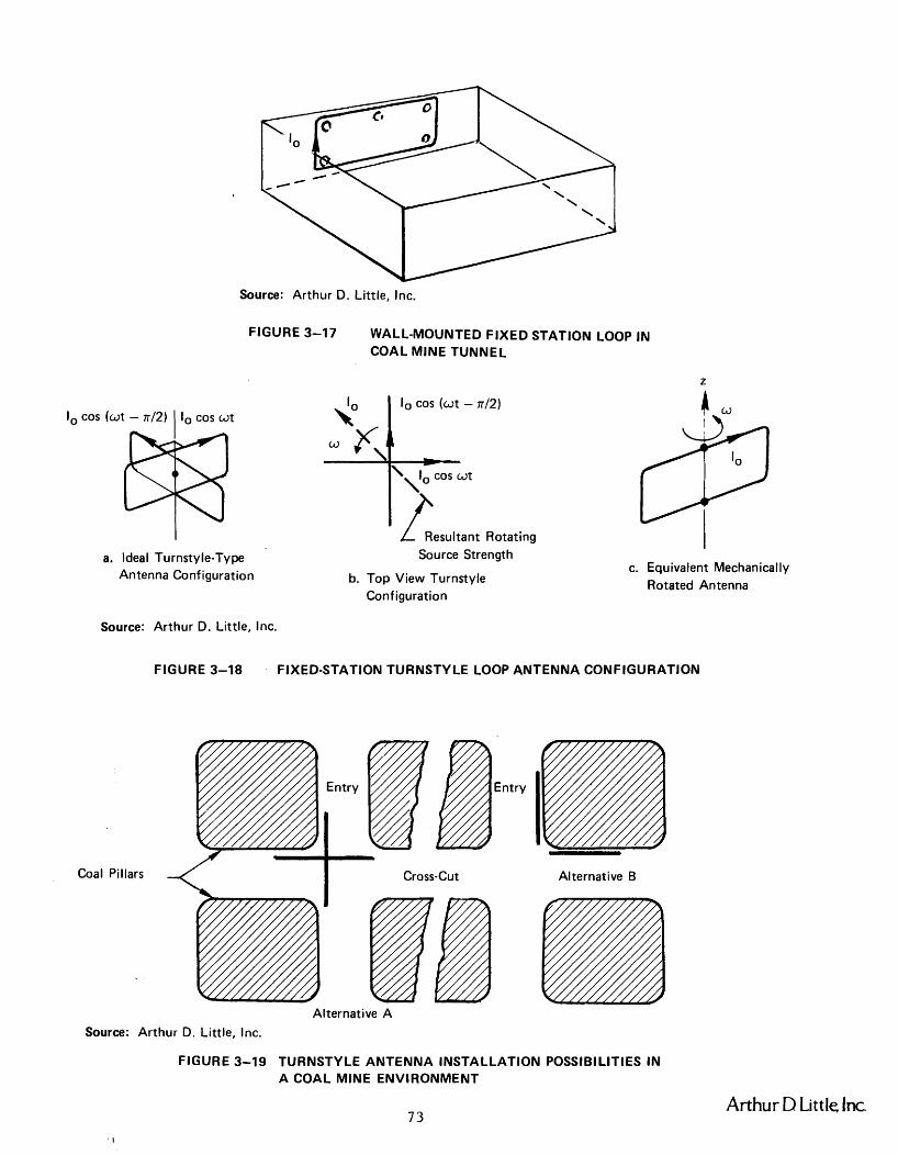
lo cos ( a t - 77/21 I lo cos at
Source: Arthur D. Little, Inc.
FIGURE 3-17 WALL-MOUNTED FIXED STATION LOOP IN COAL MlNE TUNNEL
a. Ideal Turnsty le-Ty pe Antenna Configuration
L Resultant Rotating Source Strength
b. Top View Turnstyle Configuration
I
h0
c. Equivalent Mechanically Rotated Antenna
lo cos ( a t -
Source: Arthur D. Little, Inc.
a r,l \ -
\lo COS at
P
FIGURE 3-18 FIXED-STATION TURNSTYLE LOOP ANTENNA CONFIGURATION
Entry I Coal Pillars 4 I Cross-Cut Alternative B
Alternative A
Source: Arthur D. Little, Inc.
FIGURE 3-19 TURNSTYLE ANTENNA INSTALLATION POSSIBILITIES I N A COAL MlNE ENVIRONMENT
Arthur D Little. Inc
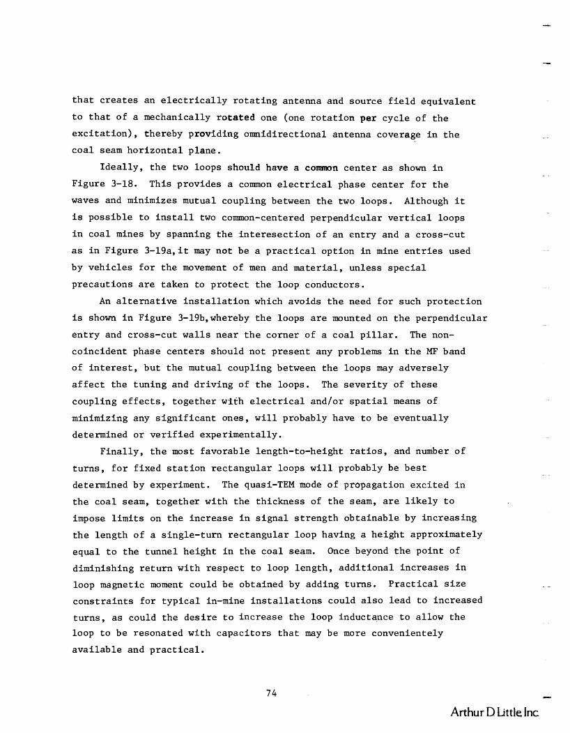
t h a t c r e a t e s an e l e c t r i c a l l y r o t a t i n g antenna and source f i e l d equiva lent
t o t h a t of a mechanically r o t a t e d one (one r o t a t i o n pe r cyc le of t h e
e x c i t a t i o n ) , thereby providing omnidirect ional antenna coverage i n t h e
c o a l seam h o r i z o n t a l plane.
I d e a l l y , t h e two loops should have a common cen te r a s shown i n
Figure 3-18. This provides a common e l e c t r i c a l phase cen te r f o r t h e
waves and minimizes mutual coupling between t h e two loops. Although i t
i s poss ib l e t o i n s t a l l two common-centered perpendicular v e r t i c a l loops
i n c o a l mines by spanning t h e i n t e r e s e c t i o n of an en t ry and a cross-cut
a s i n Figure 3-19a, i t m y no t be a p r a c t i c a l opt ion i n mine e n t r i e s used
by veh ic l e s f o r t h e movement of men and ma te r i a l , un less s p e c i a l
precaut ions a r e taken t o p r o t e c t t h e loop conductors.
An a l t e r n a t i v e i n s t a l l a t i o n which avoids t h e need f o r such p ro tec t ion
is shown i n Figure 3-19b,whereby t h e loops a r e mounted on t h e perpendicular
e n t r y and cross-cut w a l l s near t h e corner of a coa l p i l l a r . The non-
co inc ident phase cen te r s should no t present any problems i n t h e MF band
of i n t e r e s t , bu t t h e mutual coupling between t h e loops may adversely
a f f e c t t h e tuning and d r iv ing of t h e loops. The s e v e r i t y of these
coupling e f f e c t s , toge ther with e l e c t r i c a l and/or s p a t i a l means of
minimizing any s i g n i f i c a n t ones, w i l l probably have t o be eventua l ly
determined o r v e r i f i e d experimental ly.
F ina l ly , t h e most favorable length-to-height r a t i o s , and number of
t u r n s , f o r f ixed s t a t i o n rec tangular loops w i l l probably be b e s t
determined by experiment. The quasi-TEM mode of propagation exc i t ed i n
t h e coa l seam, together wi th the th ickness of t h e seam, a r e l i k e l y t o
impose l i m i t s on t h e inc rease i n s i g n a l s t r e n g t h obta inable by increas ing
t h e length of a s ingle- turn r ec t angu la r loop having a he ight approximately
equal t o t h e tunnel he igh t i n t h e c o a l seam. Once beyond t h e po in t of
diminishing r e t u r n with respec t t o loop length , a d d i t i o n a l increases i n
loop magnetic moment could be obtained by adding turns . P r a c t i c a l s i z e
c o n s t r a i n t s f o r t y p i c a l in-mine i n s t a l l a t i o n s could a l s o lead t o increased
tu rns , a s could t h e d e s i r e t o inc rease t h e loop inductance t o al low t h e
loop t o be resonated with capac i to r s t h a t may be more convenientely
a v a i l a b l e and p r a c t i c a l .
Arthur D Little Inc
The wall-mounted loop p resen t ly used f o r t h e prototype MF mine
w i r e l e s s f ixed i n s t a l l a t i o n s i n high-coal seams is a one-turn, 6 f e e t 2
high by 24 f e e t long loop giving an NA = 12 m and a loop inductance
of 27 ph. It is dr iven wi th a peak cu r ren t of about 1 amp t o produce 2
a magnetic xmemt of 14 amp-m . The bandwidth o f 12 kHz r equ i re s a Q
of 42 and a ser ies- tuned r e a l impedance l e v e l of about 2 ohms a t a
500 kHz ope ra t ing frequency . Simple in-mine experiments should be performed t o determine t h e
r e l a t i o n s h i p between loop length and s i g n a l s t r e n g t h produced i n t h e
plane of t h e loop a t d i s t ances beyond about 100 - 200 meters from t h e
loop. The r e s u l t s may r evea l t h a t a shape f a c t o r based on length-to-
he igh t r a t i o must be appl ied t o t h e geometrical a r e a t o ob ta in an
e f f e c t i v e a rea from which t h e e f f e c t i v e magnetic moment of t h e loop can
be determined. A long p iece of i n su la t ed wire capable of being dr iven
from one end and any one of s e v e r a l o t h e r po in t s along i t s periphery
should be s u i t a b l e f o r conveniently forming, mounting, and d r iv ing
r ec t angu la r loops of d i f f e r e n t length on t h e wa l l of a mine tunnel .
2. A l t e rna t ive Mode Exc i t e r s
a. Horizontal Grounded Lona Wires
Mode e x c i t a t i o n techniques o r antennas (63964965966) s i m i l a r t o those
used f o r t h e Navy's proposed worldwide ELF Sanguine communications system
may a l s o be app l i cab le f o r mine w i r e l e s s r ad io f ixed i n s t a l l a t i o n s . This
s e c t i o n b r i e f l y desc r ibes some of t h e a t t r a c t i v e s i m i l a r i t i e s between the
two a p p l i c a t i o n s , p re sen t s t h e r e s u l t s of some prel iminary f e a s i b i l i t y
c a l c u l a t i o n s f o r coa l mines, and sugges ts some avenues of f u r t h e r inves-
t i g a t i o n t h a t appear promising.
A s discussed i n Sec t ion 1 I . D of t h i s r e p o r t , recent and continuing
analyses (41'42943) and measurements (40,44) have shown t h a t coa l seams
bounded above''and below by sedimenatary rock behave a s lo s sy p a r a l l e l
p l a t e waveguides with r e spec t t o t h e propagation of r ad io waves i n t h e
LF and MF frequency bands. A t ELF,the conducting ionosphere and s u r f a c e
Arthur D Little Inc

of t h e e a r t h form t h e upper and lower boundaries of a s i m i l a r p a r a l l e l
p l a t e ear th- ionosphere waveguide w i t h i n which t r ansmi t t ed ELF waves t r a v e l
around t h e world wi th very low a t t e n u a t i o n , t o be rece ived by submerged
submarines a s depic ted by F igure 3-20. Perhaps t h e most important d i f f e r -
ence betwen t h e two waveguides is t h a t t h e c o a l seam waveguide i s f i l l e d
wi th a l o s s y medium, t h e coa l i t s e l f , i n a d d i t i o n t o be ing bounded by
lo s sy media above and below, t hus in t roduc ing shunt l o s s i n a d d i t i o n t o
t h e series l o s s of t h e "p l a t e s " i n bo th waveguides. The s p h e r i c a l s h e l l
n a t u r e of t h e ear th- ionosphere waveguide in t roduces only a d i f f e r e n t
geomet r ica l spreading l o s s f a c t o r . However, n e i t h e r of t h e s e d i f f e r e n c e s ,
t h e shunt l o s s no r t h e s p h e r i c a l s h e l l , changes t h e b a s i c n a t u r e of t h e
quasi-TEM mode of propagat ion i n t h e waveguide. I n f a c t t h e Sanguine
problem was i n i t i a l l y t r e a t e d i n terms of c y l i n d r i c a l l y spreading waves
i n a f l a t - e a r t h , p a r a l l e l p l a t e waveguide. A s p h e r i c a l "focusing"
c o r r e c t i o n f a c t o r was app l i ed t o t h e c y l i n d r i c a l wave s o l u t i o n a f te rwards .
Thus, t h e e x c i t a t i o n methods f o r one waveguide should be l a r g e l y app l i -
cab le t o t h e o the r .
The Sanguine i n v e s t i g a t o r s found t h a t t h e most e f f e c t i v e and f e a s i b l e
t r a n s m i t t i n g antenna con f igu ra t i on f o r t h e i r a p p l i c a t i o n was a p a r a l l e l
a r r a y of grounded, cen te r -dr iven , long wi re antennas. A s i n g l e long
h o r i z o n t a l w i r e is t h e s imp le s t form of such an antenna. However, t o
ach ieve t h e r equ i r ed c u r r e n t moment IR r e q u i r e s an excess ive ly l ong
antenna (and thus land having t h e des i r ed conduct iv i ty ) and/or unreasonably
h igh c u r r e n t s . High c u r r e n t s l e ad t o two consequences t h a t a r e undes i r ab l e
f o r bo th t h e Sanguine and mine w i r e l e s s a p p l i c a t i o n s , namely excess ive
power d i s s i p a t i o n and environmental ly nonpermissible f i e l d o r c u r r e n t
l e v e l s . A p a r a l l e l a r r a y g r e a t l y reduces t h e maximum l i n e a r dimensions
of t h e antenna, and d i s t r i b u t e s t h e requi red cu r r en t moment over an a r e a
which i n t u r n al lows t h e use of s e v e r a l p a r a l l e l w i r e s , each c a r r y i n g a
f r a c t i o n of t h e t o t a l c u r r e n t requi red . Furthermore, i t was found t h a t
a spac ing between h o r i z o n t a l w i r e s ( i n t h e Sanguine c a s e , 0000 AWG
copper t o c a r r y 100 amperes) of about 2 s k i n depths provides a favorab le
compromise between o v e r a l l system performance, power d i s s i p a t i o n , and
c o s t f o r t h e intended a p p l i c a t i o n . The r eade r is r e f e r r e d t o r e f e r ences
(63,64,65) f o r a more d e t a i l e d t rea tment .
Arthur D Little Inc

Ionosphere
Source: Ref. 63.
FIGURE 3-20 PROPAGATION AT ELF I N THE EARTH-IONOSPHERE WAVEGUIDE
Source: Arthur D. Little, Inc.
FIGURE 3-21 SKETCH OF A GROUNDED LONG WIRE ANTENNA INSTALLED IN A COAL MINE TUNNEL
Arthur D Little Inc

Thus, one can v i s u a l i z e a mine w i r e l e s s f i xed s t a t i o n a p p l i c a t i o n
t h a t employs one o r more h o r i z o n t a l long wi re antennas s t r u n g along t h e
roof of a mine t unne l and grounded t o t h e rock above t h e coa l seam by
roof b o l t s a s por t rayed i n Figure 3-21. The long w i r e antenna e x h i b i t s
t h e same cos$ d i p o l e p a t t e r n angular dependence a s t h e v e r t i c a l p lane
loop prev ious ly d i scussed . Thus, omnid i rec t iona l a r e a coverage can be
ob ta ined i n t h e same manner a s w i t h l oops , by employing a second long
wi re antenna perpendicu la r t o t h e f i r s t and d r iven 90' o u t of phase w i th
it i n t u r n s t y l e f a sh ion a s depic ted i n Figure 3-22. Note t h a t t h e long
w i r e antenna is b e t t e r s u i t e d than a loop t o t u r n s t y l e i n s t a l l a t i o n s
ac ros s t h e i n t e r s e c t i o n s of mine e n t r i e s and c r o s s c u t s , because i t does
no t r e q u i r e a floor-mounted w i r e which is gene ra l l y d i f f i c u l t t o p r o t e c t
from damage i n we l l - t r ave l l ed i n t e r s e c t i o n s .
The most r e c e n t estimates (43) p l a c e t h e conduc t iv i t y o f roof rock
i n c o a l mines w i t h i n t h e range of 0.01 t o 1.0 mho/m wi th a va lue o f about
0 .1 mho/m being t y p i c a l . At an ope ra t i ng frequency of 300 kHz, t h i s
produces a s k i n depth i n t h e rock , 6r, of about 2 meters. Thus, t h e
Sanguine 26 s e p a r a t i o n c r i t e r i a would al low a t least two, and perhaps
t h r e e , p a r a l l e l long w i r e s t o be placed i n a t y p i c a l mine t unne l o r e n t r y ,
depending on t h e t unne l width i n d i f f e r e n t mines o r d i f f e r e n t p a r t s of
t h e same mine. Another p o s s i b i l i t y could involve a similar o r g r e a t e r
number of cons iderab ly s h o r t e r long w i r e antennas i n s t a l l e d i n a cross-
c u t t unne l between two e n t r i e s as depic ted i n F igure 3-23. I n each case ,
t h e i n d i v i d u a l grounded wi re s could b e dr iven by s e p a r a t e t r a n s m i t t e r s
keyed-on s imultaneously v i a an audio tw i s t ed p a i r i n t e r connec t ion , o r
d r iven i n - p a r a l l e l by a s i n g l e t r a n s m i t t e r .
The most e f f e c t i v e con f igu ra t i on from t h e s t andpo in t of power d r a i n ,
communication range ,ease of i n s t a l l a t i o n and maintenance, compa t ib i l i t y
of f i x e d s t a t i o n u n i t s w i th t h e p o r t a b l e u n i t s , e t c . , would have t o be
determined a f t e r ana lyz ing t h e r e s u l t s of a s imple set of p e r f ~ r m a n c e
measurements i n mines. P a r t i c u l a r a t t e n t i o n should be pa id t o t h e
dependence of s i g n a l s t r e n g t h on t h e l eng th of t h e long wire antenna
( a s suggested f o r t h e loop antenna measurements i n Sec t ion I I I . D . ~ ) , and
t o t h e l e v e l s and v a r i a b i l i t y of t h e impedance of s imple roof b o l t (and
..111
Arthur D Little. Inc

I cos (wt - ~ 1 2 )
* I - I r. I cos wt
Source: Arthur D. Little, Inc.
FIGURE 3-22 LONG WIRE TURNSTYLE CONFIGURATION I N A N ENTRYICROSSCUT INTERSECTION
Entry
Crosscut
Source: Arthur D. Little, Inc.
FIGURE 3-23 LONG WlRE ARRAY CONFIGURATIONS I N A MINE ENTRY AND A CROSSCUT
Arthur D Little Inc
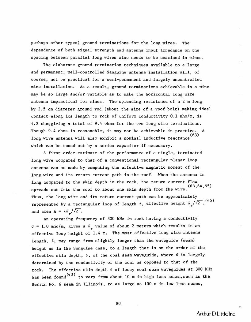
perhaps o t h e r types) ground terminat ions f o r t h e long wires . The
dependence of both s i g n a l s t r e n g t h and antenna input impedance on t h e
spacing between p a r a l l e l long wires a l s o needs t o be examined i n mines.
The e l abora t e ground te rminat ion techniques a v a i l a b l e t o a l a r g e
and permanent, well-control led Sanguine antenna i n s t a l l a t i o n w i l l , of
course, not be p r a c t i c a l f o r a semi-permanent and l a r g e l y uncontrol led
mine i n s t a l l a t i o n . A s a r e s u l t , ground terminat ions achievable i n a mine
may be so l a r g e and/or v a r i a b l e a s t o make t h e ho r i zon ta l long wire
antenna imprac t ica l f o r mines. The spreading r e s i s t a n c e of a 2 m long
by 2.5 cm diameter ground rod (about t h e s i z e of a roof b o l t ) making i d e a l
contac t along i t s length t o rock of uniform conduct iv i ty 0 .1 mho/m, is
4.2 ohm,giving a t o t a l of 9.4 ohms f o r t h e two long wire terminat ions.
Though 9.4 ohms is reasonable, i t may not be achievable i n p rac t i ce . A -
long wi re antenna w i l l a l s o e x h i b i t a nominal induct ive reactance (63)
which can be tuned out by a s e r i e s capac i to r i f necessary.
A f i r s t - o r d e r es t imate of t he performance of a s i n g l e , terminated
long w i r e compared t o t h a t of a conventional rec tangular p lanar loop
antenna can be made by computing t h e e f f e c t i v e magnetic moment of t h e
long w i r e and i t s r e t u r n cur rent path i n t h e roof . When t h e antenna i s
long compared t o t h e s k i n depth i n t h e rock, t h e r e t u r n cu r ren t flow (63,64,65)
spreads out i n t o t h e roof t o about one s k i n depth from t h e wire.
Thus, t h e long wire and i ts r e t u r n cur rent path can be approximately
represented by a r ec t angu la r loop of length R , e f f e c t i v e he ight 6 , / c , (65)
and a rea A = R6 lJ2 . r An ope ra t ing frequency of 300 kHz i n rock having a conduct iv i ty
= 1.0 mho/m, g ives a 6r va lue of about 2 meters which r e s u l t s i n an
e f f e c t i v e loop he igh t of 1 .4 m. The most e f f e c t i v e long wire antenna
l eng th , a , may range from s l i g h t l y longer than t h e waveguide (seam)
he ight a s i n t h e Sanguine case , t o a length t h a t is on t h e o rde r of t he
e f f e c t i v e s k i n depth, 6 , of t he coa l seam waveguide, where 6 is l a r g e l y
determined by t h e conduct iv i ty of t h e coa l a s opposed t o t h a t of t h e
rock. The e f f e c t i v e s k i n depth 6 of l o s sy coa l seam waveguides a t 300 kHz
has been found (43) t o vary from about 10 m i n high l o s s seams, such a s t h e
Herr in No. 6 seam i n I l l i n o i s , t o a s l a r g e a s 100 m i n low l o s s seams,
Arthur D Little Inc.

such a s the P i t t sbu rgh seam i n West Virg in ia . Maximum wi re l eng ths , Q ,
between 10 and 100 m can the re fo re be expected. Thus, t h e e f f e c t i v e loop
a r e a s of grounded long wires a r e seen t o compare favorably wi th t h a t of
t h e 2 m x 7 m r ec t angu la r f ixed s t a t i o n loop d iscussed i n Sect ion I I I . D . l .
Yet t o be determined is whether t h e r e s u l t a n t waveguide coupling
f a c t o r f o r t h e long wire is more o r l e s s favora-ble than ind ica t ed by t h e
above s i m p l i f i e d e f f e c t i v e magnetic moment a n a l y s i s , whether te rminat ion
impedances comparableto t h e impedances of tuned loops can be achieved
and e a s i l y maintained over t ime, and t o what ex ten t t h e s i g n a l s t r e n g t h
remains propor t ional t o wire l eng th a s t h e l eng th is increased. Both
a n a l y t i c a l and experimental e f f o r t s w i l l be requi red t o reso lve these
i s sues .
b. V e r t i c a l Grounded Wires
The Sanguine ELF rad io system unfor tunate ly could not use what is
perhaps t h e i d e a l antenna t o e x c i t e t h e quasi-TEM mode i n t h e ear th-
ionosphere waveguide, namely a v e r t i c a l cu r ren t source r i s i n g out of t h e
conducting e a r t h and te rminat ing i n t h e conducting ionosphere. Although
such an antenna is c l e a r l y no t f e a s i b l e f o r t h e Sanguine app l i ca t ion , i t
does become a very r e a l p o s s i b i l i t y f o r use i n t h e c o a l seam waveguide.
I n i t s s imples t form i t could c o n s i s t of a v e r t i c a l center-driven wire
grmmded at each end t o two v e r t i c a l roof b o l t s , one i n t h e roof and one
i n t h e bottom ( f l o o r ) , i n a mine e n t r y o r a c rosscu t tunnel as depic ted
i n F igure 3-24. It a l s o has t h e advantage of producing omnidirect ional
coverage i n t h e plane of t h e c o a l seam, without t h e add i t ion of a second
unf t . Another perhaps more convenient conf igura t ion may a l s o be f e a s i b l e ,
namely t h e use of a s t e e l , screw-tightened temporary roof suppor t (Fig . 3-25)
commonly used i n t h e f ace a rea p r i o r t o permanent roof bo l t ing . Such a
roof support could be mated a t each end wi th a s p e c i a l f i x t u r e designed
t o make a good grounding connection t o t h e roof and bottom, and t o
provide a means f o r connecting t h e v e r t i c a l rod coupler t o t h e t rans-
m i t t e r . This would avoid t h e need t o d r i v e a roof b o l t o r o t h e r type of
grounding rod i n t o t h e bottom. The shape of t h e f i x t u r e su r face making
contac t wi th t h e c o a l would be designed with t h e ob jec t ive of providing
Arthur D Little Inc

Source: Arthur D. Little, Inc.
FIGURE 3-24 SKETCH OF A GROUNDED VERTICAL WlRE ANTENNA INSTALLED IN A COAL MINE TUNNEL
a. Grounded Vertical Wire b. Temporary Roof c. Temporary Support d. Temporary Support Configuration Support With Shaped Mated to Roof and
Grounding Fixture Floor Bolts
Source: Arthur D. Little, Inc.
FIGURE 3-25 CONCEPTUAL SKETCHES OF VERTICAL WlRE MODE EXCITER CONFIGURATIONS
- Arthur D Little lnc

a favorably low terminat i on r e s i s t a n c e , and a cu r ren t spreading d i s t ri-
but ion i n tiie roof and bottom cons i s t en t with mode e x c i t a t i o n c o n s t r a i n t s
imposed by t h e s k i n depth i n t h e rock. The shape of t h e contac t s u r f a c e
must a l s o lend i t s e l f t o a convenient p re s su re - f i t type of i n s t a l l a t i o n
a s t h e temporary support is screw-tightened a g a i n s t t h e roof and bottom.
A s i m i l a r r e s u l t may a l s o be ob ta inab le without s p e c i a l shaping, by
i n s t a l l i n g t h e v e r t i c a l roof support s o t h a t i t mates top-and-bottom t o
two previously i n s t a l l e d roof b o l t grounding rods. A secondary advantage
of t h e s t ruc tu ra l - type of v e r t i c a l mode e x c i t e r represented by t h e
temporary roof support is t h a t i t allows t h e f ixed s t a t i o n r ad io t o be
d i r e c t l y mounted t o i t , g iv ing a phys ica l ly in t eg ra t ed mine i n s t a l l a t i o n .
A f i r s t - o r d e r es t imate of t h e performance of t h i s v e r t i c a l wire/rod
terminated source has been made and compared t o t h a t of a r ep resen ta t ive
v e r t i c a l plane loop. The v e r t i c a l monopole-type source cu r ren t generates
a $-directed magnetic f i e l d component t h a t is independent of $. Solut ion
of t h e wave equat ion f o r t h i s source d i s t r i b u t i o n gives t h e following
expression f o r t h e magnitude squared of H 4:
f o r r>>6 where 6 is t h e e f f e c t i v e s k i n depth i n t h e coa l seam waveguide,
I is t h e source cu r ren t , a i s t h e a t t enua t ion cons tant , and B is t h e
phase cons tant . I d e a l matching of t h e source cu r ren t d i s t r i b u t i o n t o
t h a t requi red i n t h e rock by t h e mode is assumed. The corresponding
f i e l d expression f o r a d ipo le source cu r ren t such a s t h a t of a rec tangular
p l ana r loop i s
f o r r>>6, where M i s t h e source loop magnetic moment, 6 is t h e s k i n r depth i n t h e rock, h is t h e he ight of t h e c o a l seam, and a and B a r e
defined above. Forming t h e r a t i o of t hese two f i e l d q u a n t i t i e s gives
t h e expression
Arthur D Little Inc

The r a t i o %L
is computed f o r i n s t a l l a t i o n s i n a representa t ive
high-loss coal seam having a seam height of 3 m and a low l o s s seam of
1 .5 m he ight . A current of 1 ampere is used f o r -wire and f 2 %' planar loop sources. A 2 m x 7 m one-turn loop\(^ = 14 a-m ) , s i m i l a r ".-
t o t h e one used f o r t h e prototype MF mine wi re less system, is assumed f o r
t h e comparison. The high-loss seam is charac ter ized by values of a =
0.047 m- l , B = 0.034 m-' , 6r = 2.3 m a t a representa t ive operat ing
frequency of 250 kHz. Thus, a r a t i o of $lL = 43 is obtained, represent-
ing a 16 dB advantage over t h e loop. The low-loss seam is charac ter ized -1 -1 by values of a = 0.013 m , B = 0.02 m * 6r = 2.9 m a t the same opera t ing
frequency, and r e s u l t s i n t h e r a t i o %,L = 132, r e p r e s e n t i n g e 21 dB
advantage. I n t h e high-loss seam, a 16 dB advantage represents only
about a 130 f t . increase i n t h e receiver-noise-limited communications
range, whereas a 21 dB advantage i n the low-loss seam represents about
I a 630 f t . increase i n opera t ing range a t 250 kHz.
Thus, t h i s method of mode coupling f o r f ixed s t a t i o n s a l s o appears
t o warrant a more thorough a n a l y t i c a l and experimental inves t iga t ion t o
see whether these favorable approximate r e s u l t s can be obtained i n
p rac t i ce . This coupling method, of course, w i l l be sub jec t t o t h e same
p o t e n t i a l problems associa ted with e s t ab l i sh ing and maintaining good
grounding connections t o t h e rock a s t h e hor izon ta l long w i r e coupling
method. Therefore, t h e l i k e l y success of both coupling methods w i l l
depend on t h e r e s u l t s of ground rod impedance experiments performed on
roof b o l t s and o the r grounding devices implanted i n the roofs and
bottoms of mine tunnels .
The conventional type of mine roof b o l t i n s t a l l a t i o n , which contacts
t h e rock a t only two points , a t the expansion wedge and a t the base p l a t e ,
w i l l probably not provide a good enough e l e c t r i c a l connection t o the
rock f o r t h e purpose of e s t a b l i s h i n g and maintaining a low impedance
ground. Some of t h e new p l a s t i c grouted b o l t s t h a t f i l l t he d r i l l hole
space between t h e s t e e l roof b o l t and the rock wi th a quick-hardening
epoxy-type of p l a s t i c may c r e a t e an even poorer connection i f t h e
grouting mate r i a l is not conductive. However, i f t h e p l a s t i c grouting
mate r i a l could be made conductive o r of high d i e l e c t r i c constant , i t
- Arthur D Little Inc

may be p o s s i b l e t o approach t h e low te rmina l r e s i s t a n c e of an i d e a l
grounding rod, and t o maintain i t over a per iod of t i m e s u f f i c i e n t t o
s e r v e t h e semi-permanent needs of an advancing coa l mine working s e c t i o n .
A t p r e sen t , i t appears t h a t q u a n t i t a t i v e knowledge on how roof b o l t and
s i m i l a r types of ground te rmina t ions work, vary over t ime, should be
i n s t a l l e d , and could be improved from an e l e c t r i c a l s t andpo in t , is n o t
a v a i l a b l e . I f and when t h i s information becomes a v a i l a b l e , a s a r e s u l t
of a c a r e f u l l y performed series of in-mine measurements, a more
d e f i n i t i v e assessment of t h e f e a s i b i l i t y of t h e long h o r i z o n t a l w i r e
and v e r t i c a l rod mode e x c i t i n g methods w i l l be poss ib l e .
3. Other Loop Antennas
A cons iderable amount of development e f f o r t has a l s o been devoted
dur ing t h e l a t e 1960's and e a r l y 1970's t o two o t h e r types of loop
.an tenna t h a t a r e worthy of b r i e f mention, namely se l f - resonant h e l i c a l
antennas by t h e Univers i ty of Innsbruck (15,16,67,68,69) in Austria and
l a r g e fe r romagnet ica l ly loaded s o l e n o i d a l loop antennas by Develco, I n c , (53)
i n t h e United S t a t e s . Both e f f o r t s were aimed a t genera t ing very high 2 magnetic moments (on t h e o rde r of 1000 amp-m ) f o r special-purpose, f ixed-
i n s t a l l a t i o n , through-the-earth, narrowband da t a communication a p p l i c a t i o n s
i n nonexplosive atmospheres, p r imar i ly i n t h e VLF and LF bands.
The Develco fe r romagnet ica l ly loaded t r ansmi t loop antennas were
designed f o r a bore h o l e through-the-earth da t a a p p l i c a t i o n s u b j e c t t o
very h igh shock and overpressure. The antennas, c o n s i s t i n g of n ine teen
f e r r i t e rods surrounded by a long, high turns-dens i ty so lenoid c o i l and
a p r o t e c t i v e f i b e r g l a s s h e l l , occupied a c y l i n d r i c a l volume about 10 f t .
long and 1 f t . i n diameter , and represented s ta te -of - the-ar t e l e c t r i c a l
and mechanical designs optimized f o r t h e a p p l i c a t i o n . The Univers i ty
of Innsbruck t r ansmi t antennas were designed f o r through-the-earth da t a
o r code comunica t ion from an underground, environmentally c o n t r o l l e d
c a v i t y , such a s might be fashioned i n an underground network of tunnels .
The antennas were center-fed, se l f - resonant , a i r - co re h e l i c a l s t r u c t u r e s
c o n s i s t i n g of a l a r g e number of t u r n s and t y p i c a l l y occupying a volume
on t h e o rde r of a meter cube. Both development e f f o r t s a l s o included
a n a l y t i c a l and experimental i n v e s t i g a t i o n s of t h e a s soc i a t ed through-the-
Arthur D Little. Inc

e a r t h propagat ion problems, and methods of op t imiz ing f e r r i t e - loaded
r ece ive antennas. The Develco propagat ion e f f o r t was p r imar i l y concerned
wi th v e r t i c a l propagat ion through t h e overburden, and t h e Univers i ty of
Innsbruck e f f o r t was p r imar i l y concerned wi th h o r i z o n t a l propagat ion
through an underground network of t unne l s i n a mountain.
Although t h e s p e c i f i c antennas developed may be i napp rop r i a t e f o r
p o r t a b l e , i n t r i n s i c a l l y s a f e , mine w i r e l e s s vo ice communication app l i -
c a t i o n s i n t h e MF band, s i m i l a r antennas and technology may i n f a c t be
a p p l i c a b l e t o permanently i n s t a l l e d , one-way, w i r e l e s s emergency warning
o r s i g n a l l i n g a p p l i c a t i o n s i n t h e ULF o r VLF band f o r mines. The
grounded h o r i z o n t a l long wire and v e r t i c a l w i r e mode e x c i t e r s d i scussed
i n t h e prev ious s e c t i o n may a l s o be candida tes f o r such a p p l i c a t i o n s .
The h igh energy s t o r a g e and/or high-power an t enna / t r ansmi t t e r i n s t a l l a t i o n s
t h a t would l i k e l y be r equ i r ed f o r long range, emergency warning app l i -
c a t i o n s could probably be l o c a t e d i n a r e a s of a mine where s i m i l a r , high-
power, n o n i n t r i n s i c a l l y - s a f e equipment is allowed, o r i n s p e c i a l l y -
p r e p a ~ d l o c a t i o n s where independent v e n t i l a t i o n and s e a l i n g could be used
t o ensure a s a f e ope ra t i ng atmosphere even i n t h e event of a mine
d i s a s t e r . Some of t h e antenna and s i g n a l l i n g technology a s s o c i a t e d w i th
t h e Develco f e r r i t e - loaded c y l i n d r i c a l antenna systems may a l s o be
a p p l i c a b l e t o re fuge s h e l t e r through-the-earth communications, e s p e c i a l l y
i n s h e l t e r s i t u a t i o n s where a la rge-area ,a i r -core loop cannot be conven-
i e n t l y deployed. Fu r the r i n v e s t i g a t i o n w i l l be requi red t o determine t h e
f e a s i b i l i t y and s u i t a b i l i t y of t h e s e antenna and s i g n a l l i n g techniques
f o r narrowband emergency warning and re fuge s h e l t e r s i g n a l l i n g app l i -
c a t i o n s .
Arthur D Little Im

E. REFERENCES
1. Chu, L. J . , "Physical L imi t a t i ons o f Omni-directional Antennas,"
J. A. P . , Vol. 19 , pp 1163-1175, December 1948.
2. Har r ing ton , R. G . , Time Harmonic Electromagnet ic F i e l d s , McGraw-
H i l l , New York, pp 264-316, 1961.
3. Wheeler, Harold A. , "Fundamental L imi t a t i ons of Small ~ n t e n n a s ," Proceedings o f t h e I. R. E., pp 1479-1484, December 1947.
4. Wheeler, Harold A . , "Small Antennas," IEEE Trans. Antennas and
Propaga t ion , Vol. AP-23, No. 4 , pp 462-469, J u l y 1975.
5. C o l l i n s , Robert E., and Zucker, F r anc i s J . , Antenna Theory, P a r t 1,
McGraw-Hill Book Co., New York, 1969.
6. Watt , A. D . , VLF Radio Engineer ing, Pergammon P r e s s , Oxford, 1967.
7. Bohley, P., Walter, C. H . , and Caldecot t , R . , "Development of t h e
Mul t i t u rn Loop Antenna a t H. F. f o r Shipboard ~ ~ ~ l i c a t i o n s , " The
Ohio S t a t e Un ive r s i t y E l e c t r o Science Laboratory, F i n a l Report
3518-1, Naval Ship Systems Command Cont rac t N00024-73-C-1023,
December 1973.
8. Wheeler, H. A . , h he Radiansphere Around a Small Antenna," Proc.
IRE, pp 1325-1331, August 1959.
9. I k r a t h , K . , Kennesbeck, W . , and Hover te r , R. T. , " ~ r e e s Performing
a s Radio Antennas," IEEE Trans. Antennas and Propaga t ion , Vol. AP-23,
No. 1, pp 137-140, January 1975.
10. Hansen, Robert C . , "Optimum Induc t ive Loading o f Short Whip Antennas,"
IEEE Trans. on Vehicular Technology, Vol. VT-24, No. 2, pp 21-29,
May 1975. ,
11. J a s i k , Henry, Ed., Antenna Engineer ing Handbook, McGraw-Hill Book
Co., New York, 1st Ed i t i on , 1961.
12. J i n k i n g s , P. W . , "Antenna Systems for L. F. ~ r a n s m i t t e r s ,'I Po in t -
to-Point Communication, pp 32-45, January 1971.
13. See ly , E. W. and Wiborg, P. H . , J r . , "Horizontal VLF Transmi t t i ng
Antennas Near t h e Ear th , " NOLC Report 721, Naval Ordnance Laboratory
Corona, Corona, C a l i f o r n i a , May 15 , 1967.
14. Co l l i n , Robert E. and Zucker, F r anc i s J . , Antenna Theory, P a r t 2,
McGraw-Hill Book Co., New York, 1969.
Arthur D Little Inc

Klein, R o y "Antennas f o r t h e VLF Region and LF Region," S c i e n t i f i c
Report No. 4, AFCRL 70-0602, Contract No. F61052-69-C-0007, Univ.
Doz. D. W. B i t t e r l i c h , VLF-Project, Univ. of Innsbruck, Innsbruck,
Aust r ia , September 1, 1970, NTIS No. AD719875.
Grissemann, Ch., e t a l , "VLF/LF Antennas and Waves i n Liquid and
Sol id Media," F ina l S c i e n t i f i c Report, AFCRL-71-0197, Contract No.
F61052-69-C-0007, Univ. Doz. D. W. B i t t e r l i c h , VLF-Project, Univ.
of Innsbruck, Innsbruck, Aust r ia , December 31, 1970, NTIS No.
AD725768.
Kueckin, J. A. "Packset Radio Antenna Measurements," IEEE In te r -
n a t i o n a l Convention Record, P a r t 5 , pp 261-270, 1966.
Krupka, Zdenek, "The Effec t of the Human Body on Radiation P roper t i e s
of Small-Sized Communication Systems," IEEE Trans. on Antennas and
Propagation, Vol. AP-16, No. 2, pp 154-163, March 1968.
Shepard, N. H. and Chaney, W. G . , "Personal Radio Antennas," IRE
Trans. Vehicular Communications, Vol. VC-10, pp 23-31, Apr i l 1961.
Maclean, T. S. M. , and Morris, G. "Short Range Active Transmit t ing
Antenna with Very Large Height Reduction," IEEE Trans. on Antennas
and Propagation, pp 286-287, March 1975.
Maclean, T. S. M. and Ramsdale, P. A. "Short Active Aer ia ls f o r
Transmission," I n t . J. Elec t ronics , Vol. 26, No. 2 , pp 261-269,
1974.
Maclean, T. S. M. , and Ramsdale, P. A. , "Active Loop-Dipole Aer ia ls , "
Proc. IEE, .Vol. 118, No. 12, pp 1698-1710, December 1971.
Anderson, A. P., and Dawoud, M. M. "The Performance of Trans i s to r
Fed Monopoles i n Active Antennas," IEEE Trans. on Antennas and
Propagation, pp 371-374, May 1973.
Fanson, P h i l i p L. and Chen, Ku-Mu, " I n s t a b i l i t i e s and Resonances
of Actively and Passively Loaded Antennas," IEEE Trans. on Antennas
and Propagation, pp 344-347, March 1974.
Dawoud, M. M . , and Anderson, A. P., "Experimental Ver i f i ca t ion of
t h e Reduced Frequency Dependence of Active Receiving Arrays,"
IEEE Trans. on Antennas and Propagation, pp 342-344, March 1974.
111
Arthur D Little. lnc.

26. Daniel , Jean-Pie r re and Te r r e t ,C . , "Mutual Coupling Between
Antennas--Optimization of T r a n s i s t o r Parameters i n Act ive Antenna
Design," IEEE Trans. on Antennas and Propaga t ion , pp 513-516,
J u l y 1975.
27. Lindenmeier, Heinz, "Active Receiving Antennas f o r Very Low
Frequencies ," Diges t of t h e 1972 Group on Antennas and Propagat ion
I n t e r n a t i o n a l Symposium,Williamsburg, V i r g i n i a , IEEE, New York,
December 11-14, 1972.
28. Turner , E. M . , IEEE Conf. Rec., X V I I I Annual Conference IEEE
Vehicu la r Technology Group, 6-8 December 1967.
29. Meinke, H . , "Acktive Antennen," Nachrichtentech. Z . , Vol. 19 ,
pp 697-705, 1966.
30. " ~ e s c r i p t i o n and S p e c i f i c a t i o n s f o r Underground Radio Transce ivers
f o r Use i n t h e Underground Workings of Mines," Chamber of Mines of
South A f r i c a , Johannesburg, January 19, 1973.
31. Vermeulen, D. J . , and B l ignau t , P. J . , "Underground Radio Communi-
c a t i o n and Its Appl ica t ion f o r Use i n Mine Emergencies," Trans.
S. A. I n s t i t u t e of E l e c t r i c a l Engineers , Vol. 52, pp 94-109,
A p r i l 1961.
32. "Mystery Radio t o t h e Rescue a t Moorgate," New S c i e n t i s t , p 641,
March 13 , 1975.
33. "F i r e Ground Communications Equipment, I t Types PRD 2 2 0 0 / P ~ ~ 2201,
Product Brochure, The P l e s sey Company Limited, Hants, England.
34. "Technical S p e c i f i c a t i o n f o r a F i r e Ground Communications System,"
P l e s sey Types PRD 2200 and PRD 2201, The P l e s sey Company Limited,
Hants , England, March 4 , 1974.
35. " ' Induc tor fone ' Equipment," Mine Telephones and S i g n a l l i n g Equip-
ment, Sheet 26, P lessey Communication Systems L td . , Manchester,
England.
36. Dushac, H. M. , "Two-Way Wireless Voice Communication System f o r
Underground Coal Mines," I n t e r n a l Report , Lee Engineer ing D iv i s ion ,
Conso l ida t ion Coal Company, February 1976, and pe r sona l communi-
c a t i o n s w i t h M r . Dushac.
Arthur D Little Inc

Chufo, R. L . , Lagace, R. L., and Wilson L. R . , "MF Mine Wireless
Radio," Proceedings of Bureau of Mines Technology Transfer Seminar
on Mine Communications, P i t t sburgh , Pa., Bureau of Mines I C
Washington, June 19 7 7.
Bradburn, R. A. , "Communications f o r Haulage Loop Arounds , " Proceedings of Bureau of Mines Technology Transfer Seminar on Mine
Communications, P i t t sburgh , Pa., Bureau of Mines I C , Washington,
June 1977.
Bradburn, R. A . , and Foulkes, J. D. , "~ongwal l Mining ~omrnunications,"
Proceedings of Bureau of Mines Technology Transfer Seminar on Mine
Communications, P i t t sburgh, Pa. , Bureau of Mines I C , Washington,
June 1977.
Co l l ins Radio Group, Rockwell In t e rna t iona l , "Mine Wireless Communi-
ca t ion System," F ina l Report, Bureau of Mines Contract H0346067, t o
be published, Spring-Summer 1978.
Lagace, R. L . , Cohen, M. L . , Emslie, A. G . , and Spencer, R. H . ,
"Propagat ion o f Radio Waves i n Coal ~ i n e s , I' Arthur D. L i t t l e , Inc . , Fina l Report, Task F--Task Order No. I . , Bureau of Mines Contract
No. H0346045, October 1975.
Emslie, A. G . , and Lagace, R. L . , "Propagation of Low and Medium
Frequency Radio Waves i n a Coal Seam," Radio Science, Vol. 11,
No. 4, pp 254-261, Apr i l 1976.
Lagace, R. L., and Emslie, A. G . , "Analysis of In-Mine Electro-
magnetic Wave Propagation Measurements," Arthur D. L i t t l e , Inc . ,
F i n a l Report, Task Order No. 4. , Bureau of Mines Contract No.
H0346045, t o be published, F a l l 1977.
Co l l ins Radio Group, Rockwell I n t e r n a t i o n a l , " ~ r o p a g a t i o n of EM
Signals i n Underground Mines," F ina l Report, Bureau of Mines
Contract No. H0366028, t o be published, May 1977.
Zikun, G. A. , Luzhnev, Yu. M . , Pozhar, E . A . , "Apparatus of Under-
ground High-Frequency Mine Rescue Communication ' ~ o n e t s k - 1 M' , "
All-Union Scientific-and-Research I n s t i t u t e of Mine Rescue Matters ,
Donetskiy P lan t , U.S.S.R.
Arthur D Little Inc

Long, R. G. , ' I Acceptabi l i ty Guidelines f o r Performance Character-
i s t i c s of Underground Pager Phones," Arthur D. L i t t l e , Inc . ,
F i n a l Report, Bureau of Mines Contract No. 50166085, Apr i l 1977.
Wolf, R. A. , " ~ e s i g n o f E l e c t r i c a l Equipment f o r I n t r i n s i c
Safe ty ," Proceedings of t h e F i r s t WVU Conference on Coal Mine
Electrotechnology, West V i rg in i a Univers i ty , August 2-4, 1972.
Redding, R. J . , INTRINSIC SAFETY--The s a f e use of e l e c t r o n i c s i n
hazardous loca t ions , McGraw-Hill, London, 1971.
Moon, P., and Spencer, D. E . , F i e ld Theory f o r Engineers,
D. VanNostrand Company, Inc . , Pr ince ton , New Je r sey , 1961.
Wait, J . R . , "Receiving P rope r t i e s of a Wire Loop wi th a Spher-
o i d a l Core," Canadian Journa l of Technology, Vol. 31, pp 9-14,
January 1953.
Dunlavy, J. H. Jr. , " ~ e s i g n Aspects of F e r r i t e Antennas i n t h e
Frequency Range Below 30 MHz," Proceedings of t h e 1968 E lec t ron ic
Components Conference, Washington, D. C . , May 9, 1968.
Belrose, J. S. , "Ferromagnetic Loop Aer i a l s , I 1 Wireless Engineer,
Vol. 32, pp 41-46, February 1955.
Rorden, L. H . , Bacon, L. C . , and Smith, R. L., "Underground
Telemetry System Development--Design Def in i t i on phase," Develco,
Inc . , In t e r im Report on Defense Nuclear Agency Contract No.
DNA 001-74-C-0298, J u l y 1975.
Sne l l ing , E. C . , " F e r r i t e s f o r Linear Appl ica t ions , P a r t I - Proper t i e s , " IEEE Spectrum, Vol. 9 , No. 1, pp 42-51, January 1972.
Sne l l ing , E. C . , " F e r r i t e s f o r Linear Appl ica t ions , P a r t I1 - Performance Requirements , I 1 IEEE Spectrum, Vol. 9 , No. 2, pp 26-32,
February 1972.
Sams, H. W . , Handbook of E lec t ron ic Tables and Formulas, 2nd Ed.,
Herr ington, D. , and Meacham, S., Ed., Howard W. Sams and Co., Inc.
Bobbs-Merrill Co., Inc . , Indianapol i s , 1962.
Bohley, P . , David, R. J . , and Walter , C. H . , a an-pack Loop
Antenna System," The Ohio S t a t e Univers i ty ElectroScience Labor-
a t o r y , F i n a l Report 3824-2, Naval Regional Procurement Of f i ce
Contract N00123-74-C-0645, December 1974.
Arthur D Little. Inc

Davis, R. J . , he Development of a Mul t i t u rn Loop Antenna f o r
t h e AN/PRC-77 , I 1 The Ohio S t a t e Un ive r s i t y E lec t roSc ience Laboratory,
Technica l Report 3824-1, Naval Regional Procurement Of f i ce Cont rac t
~00123-74-C-0645, December 1974.
Bohley, P. , and Newman, E. H . , "Development of a VHF M u l t i t u m
Loop Antenna f o r Seismic Sensor Systems," The Ohio S t a t e Univer-
s i t y E lec t roSc ience Labora tory , F i n a l Report Vol. ill, Uni ted S t a t e s
Army Materiel Command Contract DAAG39-72-C-0041, March 1973.
Newman, E., Bohley, P. , and Walter, C. H . , "Two Methods f o r t h e
Measurement of Antenna E f f i c i ency , " IEEE Trans. on Antennas and
Propaga t ion , Vol. AP-23, No. 4 , pp 457-461, J u l y 1975.
King, H. E. , " C h a r a c t e r i s t i c s of Body-Mounted Antennas f o r Persona l
Radio S e t s , " IEEE Trans. on Antennas and Propagat ion, pp 242-244,
March 1975.
Reggia, F . , "Low-Profile VHF Antennas f o r Seismic Detec t ion Systems,"
HDL-TR-1635, U. S. Army Materiel Command, Harry Diamond Labora to r i e s ,
Washington, J u l y 1973, NTIS No. AD766703.
Be rns t e in , S. I., e t a l , "~ong-Range Communications a t Extremely
Low Frequencies ," Proceedings of t h e IEEE, Vol. 62, No. 3 , pp 292-
312, March 1974.
Burrows, M. L. , "ELF Antennas, " P r e s e n t a t i on a t IEEE Antennas and
Propagat i on Soc ie ty Chapter Meeting, Washington, D. C. , October 19 ,
1971.
IEEE Transac t i ons on Communications, S p e c i a l I s s u e on Extremely
Low Frequency (ELF) Communications, Vol. COM-22, A p r i l 1974.
W a i t , J. R., "Earth-Ionosphere Cavity Resonances and t h e Propa-
g a t i o n of ELF Radio Waves," Radio Science, Vol. 69D, pp 1057-1070,
August 1965.
Nessler, N. , "Theo re t i c a l and Experimental S tud i e s o f VLF and LF
Waves," F i n a l S c i e n t i f i c Report--1973, AFc~~-T~-73 -0174 , Contract
No. F 44620-72-C-0052, Un ive r s i t y o f Innsbruck, Innsbruck, A u s t r i a ,
February 28, 1973, NTIS No. AD753778.
Nessler, N . , "Considerat ions on t h e Dimensioning of F e r r i t e
Antenna Ampl i f ie r s i n t h e VLF Regions," S c i e n t i f i c Report No. 2 ,
Arthur D Little Inc

AFCRL-69-0420, Contract No. F61052-69-C-0007, Univ. Doz., D r . W.
B i t t e r l i c h , VLF-Project, Univers i ty of Innsbruck, Innsbruck, Aus t r i a ,
J u l y 15 , 1969, NTIS No. AD695489.
69. Lukavec, R. , " ~ e a s u r e d P r o p e r t i e s of Small Self-Resonant H e l i c a l
Antennas a t Low Frequencies f o r Appl ica t ion i n D i s s i p a t i v e Media, "
S c i e n t i f i c Report No. 8 , AFCRL-69-0096, Contract No. 61(052)-902,
Univ. Doz., D r . W. B i t t e r l i c h , VLF-Project, Univers i ty of Innsbruck,
Innsbruck, A u s t r i a , December 1, 1968, NTIS No. AD684578.
Arthur D Little Inc

(This page i n t e n t i o n a l l y l e f t blank)
U
Arthur D Little. Inc

I V . COUPLING TO EXISTING CONDUCTORS I N MINES
A. SUMMARY
To evalua te the p o t e n t i a l advantages and p r a c t i c a l i t y of extending
mine wi re l e s s ranges by coupling t o e x i s t i n g conducting s t r u c t u r e s i n
mines, t heore t i ca1 .equa t ions were developed, re la t ing loop antenna s t r e n g t h ,
frequency, and i t s d i s t ance from two-wire cables and s t r u c t u r e s , t o t h e
cu r ren t and vol tage induced i n t h a t s t r u c t u r e by t h e loop antenna. These
equations al low one t o compute not only t h e loop-to-structure coupling
but a l s o loop-to-loop coupling v i a t h e two-wire s t r u c t u r e . Resul t s com-
puted f o r t h r e e frequencies (3 , 100, and 1000 kHz) i n d i c a t e t h a t :
a performance improves with closeness t o t h e two-wire s t r u c t u r e ,
increased sepa ra t ion of t h e wires,and increas ing frequency up
t o about 0.5-1 MHz i n a mine tunnel ;
a loop-to-loop communications along a haulageway appear p r a c t i c a l
i n t h e presence of a t r o l l e y wire system and may a l s o be
usable i n the presence of untwisted cables and s i n g l e wires
a t tached t o t h e r i b s ;
a coupling t o twis ted p a i r cables is severe ly reduced over t h a t
f o r untwisted p a i r s ;
a performance should be s i g n i f i c a n t l y reduced f o r loops loca ted
i n tunnels adjacent t o t h e one i n which t h e conductors a r e
located.
The r e s u l t s f o r r ep resen ta t ive cases of i n t e r e s t a r e p lo t t ed .
B. INTRODUCTION
The ob jec t ive i s t o c a l c u l a t e t h e coupling between a loop antenna
which can reasonably be c a r r i e d by a miner and conductors which a r e com-
monly found i n mines. The antenna loop has a magnetic moment of M=NIA
where N i s t h e number of t u r n s , I is t h e cu r ren t i n t h e loop, and A i s
i t s area . For an antenna which i s wrapped around a man, a reasonable 2 source s t r eng th i s M = 112 t o 4 amp-turn meter . We w i l l use t h e va lue
1 amp-turn meter2, here. The conductors a v a i l a b l e f o r coupling t o are :
a telephone l i n e s ( twis ted and untwisted p a i r s ) ;
t r a i l i n g cables ( e i t h e r twisted p a i r s , twin-leads o r more
complex s t r u c t u r e s ) ;
a t r o l l e y w i r e l r a i l (approximated here by a two-wire l i n e ) and power d i s t r i b u t i o n l i n e s ( a conventional 3-phase cable f o r mine use) .
Arthur D Little. lnc

The simpler, in-air case w i l l be examined t o g e t upper bounds f o r perfor-
mance, These r e s u l t s should be appl icable within t h e haulageways where
t h e conductors a r e located, Transmitter requirements w i l l be more severe
f o r coupling beyond t h e immediate tunnel cross-section i n which the con-
ductors a r e located because of the add i t iona l losses introduced by the
coa l and surrounding rock,
C , REPRESENTATIVE GEOMETRIES
We f i r s t examine severa l d i f f e r e n t cases of coupling between a
loop, assumed of i n f i n i t e s i m a l s i z e , and twin-lead and twisted-pair
conductors, The assumption of an in f in i t e s imal loop is j u s t i f i e d i f
the diameter of t h e loop, approximately 0.3 m, is much l e s s than the
wavelength of t h e s igna l , and t h e loop-to-conductor spacing, Table 4-1
summarizes severa l s i t u a t i o n s of i n t e r e s t , Figure 4-1 shows severa l bas ic
arrangements of the t ransmit t ing loop with respect t o simple twin-lead
conductors, I f t h e miner wears the t ransmit t ing antenna as a bandolier
around h i s body, then s i t u a t i o n s l a andlb represent cases where t h e
planes of t h e twin-leads and t h e loop a r e hor izonta l ; while s i t u a t i o n s
lcand Idrepresent cases where the plane of t h e twin-lead cable is ver-
t i c a l but the loop i t s e l f is s t i l l i n t h e hor izonta l plane, Si tuat ions
leand l f represent cases where the cable d i r e c t i o n is p a r a l l e l t o the
TABLE 4-1
TYPICAL DIMENSIONS FOR STRUCTURES OF INTEREST I N A M I N E
Frequencies 3kHz t o lMHz
Wavelengths 10 5 m t o 3 x l O m 2
Trolley Lines ( t r o l l e y wire t o l m (low coal) t o 2m (high coal) t rack spacings)
Twisted P a i r s (cable diameters) O.O2m t o 0.07m
F l a t Twin-Lead (lead spacings) 0.015m t o 0.05m
Three Conductor Cables (cable diameters) 0.02m t o 0.08m
Antenna-to-Cable Distances 2m
Source: Arthur D. L i t t l e , Inc., Essex and Anaconda Catalogs
Arthur D Little Inc
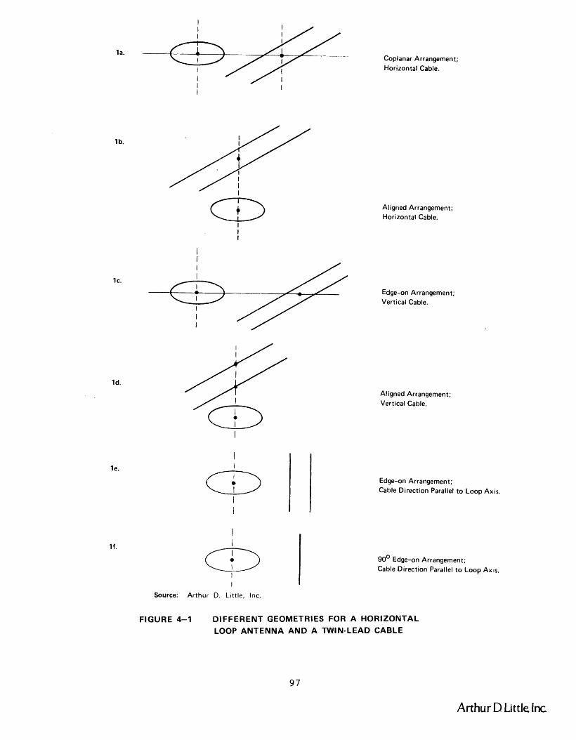
la. I,$//.-. Coplanar Horizontal Arrangement; Cable.
I I
I
I
& I
I
Source: Arthur D. Little, Inc.
Aligned Arrangement; Horizontal Cable.
Edge-on Arrangement; Vertical Cable.
A1 igned Arrangement; Vertical Cable.
Edge-on Arrangement; Cable Direction Parallel to Loop Ax is.
90' Edge-on Arrangement; Cable Direction Parallel to Loop AXIS.
FIGURE 4-1 DIFFERENT GEOMETRIES FOR A HORIZONTAL LOOP ANTENNA AND A TWIN-LEAD CABLE
Arthur D Little Inc
a x i s of t h e loop, but i n case E t h e plane of t he twin-lead cable con-
t a i n s t h e loop a x i s , while i n case F t h e plane of t h e twin-lead cable i s
perpendicular t o a plane conta in ing t h e a x i s of t h e loop. These l a t t e r
two s i t u a t i o n s where t h e d i r e c t i o n of t h e cable is p a r a l l e l t o the a x i s
of t h e loop a r e not considered a s r e a l i s t i c a l t e r n a t i v e s . Figure 4-2
shows s i m i l a r arrangements f o r a twisted-pair but s i n c e t h e r e i s no
unique plane which contains only t h e two w i r e s of t he twisted-pair ,
t h e r e a r e less cases of i n t e r e s t .
I n genera l , t he t ransmi t loop antenna and the mine s t r u c t u r e t h a t
i s a c t i n g a s the conductor w i l l no t have such simple r e l a t i o n s h i p s a s
those shown i n Figures 4-1 and 4-2. The coplanar r e l a t i o n s h i p s i n l a and
l b a r e reasonable approximations f o r most s i t u a t i o n s where a ho r i zon ta l
twin-lead o r a twisted-pair a r e mounted on t h e s i d e wa l l of a tunnel
o r hung from t h e roof . I n low coa l , t he conductor i s unl ike ly t o be
more than 112 m above o r below the plane of t h e t r ansmi t t ing antenna
which may be 2 m t o 600 m away. A t 2 m t h e angle above o r below t h e
t r a n s m i t t e r loop plane is 14O while a t 600 m t h e angle i s 0.05O.
Cos 14O i s about 0.97, so t h e f i e l d s t r e n g t h a t a conductor 112 m
above the plane of the t ransmit loop is approximately equal t o t h a t f o r
a conductor i n t h e plane of t h e t ransmit loop. Assuming a 2 m high
seam f o r high-coal, t h e maximum ang le of t h e conductor above t h e plane
of t he t r a n s m i t t e r loop i s 37O, which has a cosine of 0.80, so t h e
absence of coplanar i ty is more s i g n i f i c a n t here . However, a t d i s t ances
g r e a t e r than 6 m, t h e cop lana r i ty assumption i s a reasonable approxi-
mation, a s shown i n Figure 4-3.
Simil-arly, when t h e twin-lead cable i s i n the h o r i z o n t a l plane and
suspended from t h e roof away from a w a l l , case l a is s t i l l a reasonable
desc r ip t ion of t h e s i t u a t i o n a s t h e t r ansmi t t ing loop approaches from
600 m t o 6 m i n high-coal, and t o 2 m i n low-coal. There can then be a
t r a n s i t i o n region a s t h e t r ansmi t t ing loop moves under t h e cab le u n t i l
t h e s i t u a t i o n of l b i s achieved.
.I.
Arthur D Little. lnc

Coplanar Arrangment (similar to l a and Ic)
Aligned Arrangement (similar to 1b and Id )
Edge-on Arrangement (similar to l e and I f )
Source: Arthur D. Little, Inc.
FIGURE 4-2 DIFFERENT GEOMETRIES FOR A HORIZONTAL LOOP ANTENNA AND A TWISTED-PAIR CABLE
99 Arthur D ~ i t t l e lnc I
(a) LOW COAL
I I I I I , I I 2 20 200 600
I I
Horizontal
In Meters (log scale) + Separation
Center Line of Twin Lead
Coplanarity Assumption Poor Over This Range \
Aligned Arrangement ~ a i i d The Assumption of Coplanarity is ~ o o d to 3% Over This Range
(b) HIGH COAL
The Assumption of Coplanarity is
Good to 3% Over This Range
Horizontal Center Line of Twin Lead
he Assumption of Coplanarity is Poor Separation Aligned Arrangement Valid Over This Range on a Log Scale (m)
Source: Arthur D. Little, Inc.
FIGURE 4--3 RANGES OF VALIDITY OF COPLANARITY ASSUMPTIONS
- Arthur D Lit tlo Inc

Similar ranges of v a l i d i t y apply t o t he case where t he twin-lead
cable i s i n the v e r t i c a l plane, A specia l case of t h i s is t he t ro l l ey-
wire system, which because of i ts s i z e with respect t o the tunnel dimen-
s ions , t he loop posi t ion w i l l always lay v e r t i c a l l y somewhere between
the trol ley-wire and the r a i l re turn ,
D, COUPLING TO SIMPLE TWO-WIRE LINES
1. Case l a - Coplanar Geometry
a, Elec t r i c F ie ld Method
This case has been considered i n d e t a i l by Albert A, Smith, Jr, i n
a paper ca l l ed "The Response of a Two-Wire Transmission Line Excited by
t h e Non-uniform Electromagnetic F ie lds of a Nearby Loop, " published i n
t h e IEEE Transactions on Electromagnetic Compatibility, EMC-16, 196-200
(1974). The equations given i n t h i s paper fo r the near, o r inductive-
f i e l d , case a r e va l id over most of t h e ranges of parameters of i n t e r e s t
to us, see Table 4-2. The var iab le BR = 2mR/X should be much l e s s than
unity; R is t h e spacing between t he loop and the cable and X is the
wavelength of t h e s igna l i n a i r .
TABLE 4-2
REGIONS OF VALIDITY FOR USING BR <<I CRITERION, THE INDUCTIVE-FIELD APPROXIMATION
(IN A I R ) f (kHz) 3 100 1000
The e n t r i e s i n the t ab le a re values of BR = ~ I T R / X i n a i r .
(1) rans sit ion zone between inductive and radia t ion f i e l d s .
(2) Radiation - f i e l d zone.
Source: Arthur D . L i t t l e , Inc.
Arthur D Little Inc
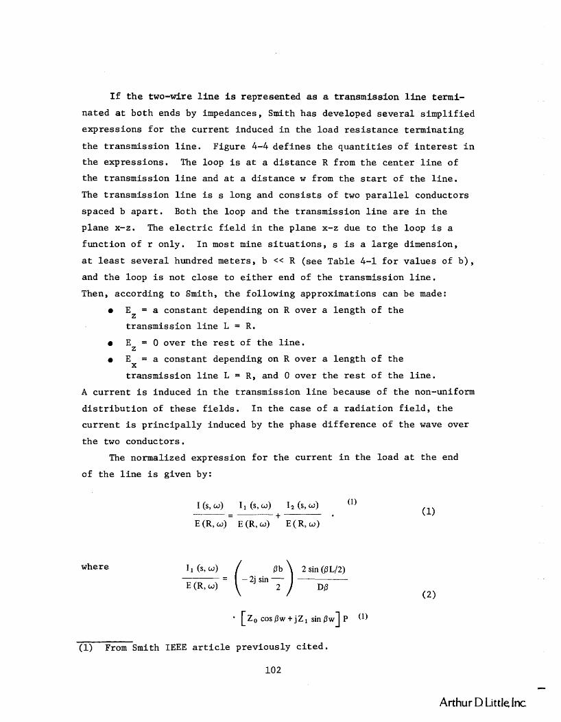
I f t h e two-wire l ine is represented as a transmission l i n e termi-
na ted a t both ends by impedances, Smith has developed seve ra l s impl i f i ed
expressions f o r t h e cur rent induced i n the load r e s i s t a n c e terminat ing
t h e t ransmission l i n e . Figure 4-4 def ines t h e q u a n t i t i e s of i n t e r e s t i n
t h e expressions. The loop i s a t a d i s t ance R from t h e center l i n e of
the t ransmiss ion l i n e and a t a d i s t ance w from t h e s t a r t of t he l i n e .
The t ransmission l i n e is s long and c o n s i s t s of two p a r a l l e l conductors
spaced b a p a r t . Both the loop and t h e t ransmission l i n e a r e i n the
plane x-z. The e l e c t r i c f i e l d i n t h e plane x-z due t o t h e loop i s a
funct ion of r only. I n most mine s i t u a t i o n s , s is a l a r g e dimension,
a t l e a s t s e v e r a l hundred meters , b << R (see Table 4-1 f o r va lues of b ) ,
and t h e loop i s not c lose t o e i t h e r end of the t ransmission l i n e .
Then, according t o Smith, t h e fol lowing approximations can be made:
a EZ = a cons tant depending on R over a length of t h e
t ransmission l i n e L = R.
a EZ = 0 over t h e r e s t of t h e l i n e .
a E = a constant depending on R over a length of t h e X
t ransmission l i n e L = R, and 0 over t h e r e s t of t h e l i n e .
A cur ren t i s induced i n t h e t ransmission l i n e because of t h e non-uniform
d i s t r i b u t i o n of these f i e l d s . I n t h e case of a r a d i a t i o n f i e l d , t h e
c u r r e n t i s p r i n c i p a l l y induced by t h e phase d i f f e rence of t h e wave over
t h e two conductors.
The normalized expression f o r t h e cur rent i n the load a t t h e end
of t h e l i n e is given by:
where 2 sin (PL/2)
E (R, 4 DP
(1) From Smith IEEE a r t i c l e previously c i t e d .
102
Arthur D Little Inc

Source: Smith, IEEE Trans EMC, EMC-76 196-200 (1974)
FIGURE 4-4 GEOMETRY OF THE TRANSMITTING LOOP AND TRANSMISSION LINE FOR THE CASE OF FIGURE 4-l(a)
Arthur D Little Inc
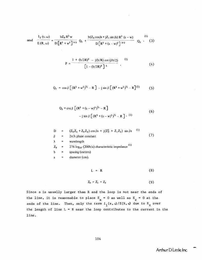
I2 ( s 9 4 bZo R2 w b(Zo cosps + jZ1 sin 0s) R2 (S - W) (1) and -------- - -
E ( R , w ) D [ R ~ + W ~ ] ~ ' ~ Q1 + D [R2 + (s - w ) ~ ] 3'2
Q2 (3 )
1 + (b/2R)2 - j(b/R) cot (pbl2) ('1 p = - -
[l - (b/2R)'] 9
D = (ZoZl+ZoZ2)cos/3s + j(z; + ZlZ2) sines /3 = 27r/h phase constant
h = wavelength
Zo = 276 loglo (200b/a) characteristic impedance (1)
b = spacing (meters)
a = diameter (cm).
Since s is usual ly l a r g e r than R and the loop i s not near the ends of
t h e l i n e , i t is reasonable t o p l ace E = 0 a s w e l l a s EZ = 0 a t t h e X
ends of t h e l i n e . Then, only t h e term I l ( s , w ) / E ( R , ~ due t o E z over
the length of l i n e L = R nea r t h e loop con t r ibu te s t o t h e cu r ren t i n the
l i n e .
- Arthur D Little. Inc.

A s R grows l a r g e r , t h e na tu re of t h e loop-caused f i e l d a t t h e l i n e
changes from induct ive t o r a d i a t i v e . Then, t h e equat ions a r e modified
t o :
except
(11 I1 (s, a )
- . . . as above . . . E (R, a )
1 - j (b/2R) cot (pb/2) ('1 P =
1 - ( b / 2 ~ ) ~ 9
I2 (s, a ) bZo Rw b(Zo cosps + jZ1 sinps) R(s -w) (1 1
and - - E (R, a ) D(R? + w2)
QI + D [ R ~ + (S - w ) ~ ]
Q 2 * (12)
wi th Q1 and Q2 a s above and Z = Z2 = ZO. 1 These complex expressions must be rearranged s o t h a t t h e i r magni-
tudes can be evaluated. Since the induct ive- f ie ld assumption is v a l i d
over most of t h e ranges of i n t e r e s t t o us , and s i n c e i t i s reasonable
t o assume t h a t w > R f o r a l l cases of i n t e r e s t t o us , only the expres-
s i o n f o r I is rearranged. Then we have: 1
sin (+) sin
If R << A, and b << R, then;
Arthur D Little Inc

The va lue of t h i s t r a n s f e r admittance
h a s been evaluated below f o r t h r e e cases:
1. Twin-lead, telephone and power cable
b = 0.04 m; Zo = 280.6 ohms
R < 20 m; T = -77dB - R > 200 m; T = -78dB -
* 2. Low coal , t r o l l e y system (Two-wire l i n e a p n r o x i ~ a t i o n )
b = 1 m; a = 0.05 m; Z = 442.4 ohms 0
R < 20 m; T = -53dB -
R > 200 m; T = -55dB - * 3. High coa l , t r o l l e y system (Two-wire l i n e approximation)
b = 2 m; a = 0.05 m; Z = 525.3 ohms 0
R < 20 m; T = -48dB - R > 200 m; T = -50dB -
Table 4-3 l is ts t h e va lues of e l e c t r i c a l f i e l d s t r e n g t h i n t h e plane of
t h e loop a t 2 m from a loop antenna i n a i r a s a funct ion of frequency.
It a l s o i n d i c a t e s t h e reduct ion i n f i e l d s t r eng th a t increas ing d i s t ances .
Using t h e s e f i e l d s t r e n g t h s and t h e va lues of T given above, t h e va lues
of cu r ren t induced i n t h e conductors and t h e matched loads have been
ca l cu la t ed and tabula ted i n Table 4-4.
b. Magnetic F ie ld Method
The v a l u e of t h e s e induced c u r r e n t s can a l s o be est imated by an
equiva lent s impler method based on t h e vo l t age induced i n t h e p a i r by
t h e loop magnetic f l u x c u t t i n g t h e p a i r . I n t h e above coplanar case ,
t h e 0-component of t h e loop f i e l d , He , would be used, and the induced
v o l t a g e est imated by using t h e approximation of an equiva lent cons tant
f l u x d e n s i t y d i s t r i b u t i o n B =p H (R) l i nk ing an a rea enclosed by t h e 8 0 8
sepa ra t ion b of t h e cab le p a i r over a length L along - t h e p a i r . Here, L
i s equal t o ZR, i n s t ead of R , where R i s t h e s h o r t e s t d i s t a n c e from t h e
cen te r of t h e loop t o t h e midpoint between t h e cable conductors a s before ,
and H (R) i s t h e va lue of loop magnetic f i e l d a t t h i s midpoint. 8
* I n p r a c t i c e , t h e t r o l l e y l i n e c h a r a c t e r i s t i c impedance i s c lose r t o 200 ohms, because of t h e l a r g e e f f e c t i v e diameters of t h e t r o l l e y wire l feed conductors and t h e r a i l r e t u r n conductors.
I
Arthur D Little, Inc.

TABLE 4-3
VALUES OF E I N THE PLANE 9
OF A LOOP AT A DISTANCE R AWAY I N A I R 2 (Source Strength M = 1 amp-meter )
Frequency 3kHz lOOkHz lMHz
R(m)
2 480pv/m 15,80Opv/m 158,0OOpV/m * * *
20 -40dB -40dB -39dB
200 -80dB -79dB -67dB
500 -96dB -93dB -76dB
Source: Arthur D. L i t t l e , Inc.
*dB reduction with inc reas ing d i s t ance r e l a t i v e t o 2 meter values
Arthur D Little Inc.

TABLE 4-4 CURRENTS I N p AMPERES TNDUCED I N CONDUCTORS
FOR THE SITUATION OF FIGURE 4- la (IN AIR)
( a ) Frequency = 3kHz
b (m) 0.04
R (m)
2 0.06
(b) Frequency = lOOkHz
( c ) Frequency = lMHz
Source: A r t h u r D . L i t t l e , I n c .
E n t r i e s i n t h e Table a r e c u r r e n t s i n PA f o r a s o u r c e s t r e n g t h o f M = 1 amp-meter2 and matched t e r m i n a t i o n s Z = Z2 = Z0
1
* Dash i n d i c a t e s t h a t i n d u c t i v e f i e l d approximat ions do n o t a p p l y a t t h e s e ranges f o r t h e i n d i c a t e d f r e q u e n c i e s .
I
Arthur D Little Inc.

I n the induct ive f i e l d region of i n t e r e s t , examination of t h e
r e c i p r o c a l problem of coupling from a long two-wire l ine t o a small
loop r evea l s t h a t t h e mutual coupling impedance Zm = Vloop/Iline, i s
i d e n t i c a l f o r both t h e coplanar-la and coax ia l (a l igned) - l b config-
u r a t i o n s . Therefore, f o r t h e a l igned case ( l b ) one can simply use t h e
coplanar va lues computed above, o r u t i l i z e a va lue of L equal t o R, (as
used i n Smith's approximate E-field method) i n o rde r t o compensate f o r
t h e f a c t o r of two introduced by t h e Hr f i e l d t h a t now l i n k s t h e cable ,
and which is twice t h e s t r e n g t h of t h e % loop f i e l d i n t h e induc t ive
f i e l d region. The approximate f l u x l inkage method of computation is
i l l u s t r a t e d below f o r t h i s coaxia l (al igned) case l b i n which t h e
r-component, Hr, of t he loop f i e l d i s the appropr ia te one t o use.
(This r e s u l t has been v e r i f i e d by eva lua t ing the appropr i a t e i n t e g r a l s . )
2 . Case l b - Aligned Geometry, Magnetic F ie ld Method
To e s t ima te t h e vol tage induced i n the twin l e a d cable conductors
i n the a l igned case l b , t h e H f i e l d s t r e n g t h w i l l be assumed constant r over a l i n e length L = R, and zero elsewhere on the l i n e , f o r computing
the e f f e c t i v e f l u x l i nk ing t h e cable a s noted above. Therefore t h e
requi red H f i e l d s t r e n g t h i s t h a t produced by t h e loop a t a d i s t ance r R , which again is t h e s h o r t e s t d i s t ance from t h e cen te r of t h e loop t o
the midpoint between the cable conductors. The e f f e c t i v e a r e a being
l inked by t h e f l u x i s given by Lb = Rb. The r e l evan t expressions a r e :
where t h e symbols have t h e i r usua l meaning. Now t h e f l u x i s given by:
$ = Ba - po H, (Rb) (18)
Arthur D Little Inc.

and by ~ e n z ' s law, t h e induced s e r i e s v o l t a g e is given by:
S u b s t i t u t i n g t h e exp re s s ion f o r H and s imp l i fy ing , l e a d s t o t h e r express ion :
If 27rR << A, then
The corresponding exp re s s ions f o r t h e coplanar case - l a , which
u t i l i z e t h e loop He f i e l d component a t 8 = n/2 a r e :
V " w PO (2Rb) Hg
and
which reduces t o Equation (21) when 2nR<<X, a s i t should.
-. Arthur D Little, Inc.

Table 4-5 presents the r e s u l t s of these calcula t ions f o r M = 1 ampere-
meter2 and t he parameters l i s t e d . The corresponding currents induced
i n the load a t each end of the matched cable is then given by:
The equivalent transmission l i n e exc i t a t ion and terminations a r e shown
i n Figure 4-5. A s discussed above, the induced voltage is i den t i c a l f o r
both the aligned and coplanar (shown) geometries . The above technique
can a l s o be applied t o the cases of a rb i t r a ry loads Z and Z2 terminating 1 the transmission l i n e ,
Loop Transmitter
Source: Arthur D. Little, Inc.
FIGURE 4-5 EQUIVALENT TRANSMISSION LINE CIRCUIT FOR INDUCED VOLTAGE AND CURRENT (Case of Z1 = 22 = ZO)
3, Unfavorable Geometries
Because the plane of the cable conductors is ro ta ted through 90'
between the s i t ua t i ons of Figures 4-la and l c and Figures 4-lb and Id,
the f l ux linkage i n s i t ua t i ons approximating those of Figures 4-lc and Id
is subs t an t i a l l y reduced below those of the two cases considered above,
causing a corresponding major reduction i n the magnitude of the induced
signals. Al ternat ively s t a t ed , i n Figure 4-lc, the values of E a t 0
t h e two conductors a r e equal because they a r e the same dis tance from
Arthur D Little fnc.
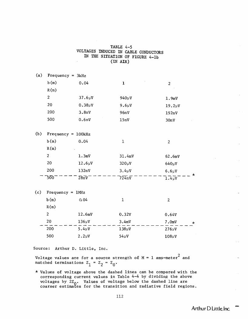
TABLE 4-5 VOLTAGES INDUCED IN CABLE CONDUCTORS
IN THE SITUATION OF FIGURE 4-lb
A=)
(a ) Frequency = 3kHz
b (m) 0.04 1
R (m)
2 37 . 6pV 940pV
20 0.38pV 9.6pV
200 3.8nV 9 6nV
500 0.6nV 15nV
(b) Frequency = lOOkHz
b (m) 0.04
R (m)
( c ) Frequency = 1MHz
b (m) 0.04 1 2
R(m)
2 12.6mV 0.32V 0.64V
20 136pV 3.4mV 7 .OmV * - - - - ---------------------------- 200 5 . 4pV 138pV 276pV
500 2.2pV 54pV 108pV
Source: Arthur D. L i t t l e , Inc.
Voltage va lues a r e f o r a source s t r e n g t h of M = 1 amp-meter2 and matched te rmina t ions Z1 = Z2 = ZO.
* Values of vo l t age above t h e dashed l i n e s can be compared wi th t h e corresponding c u r r e n t va lues i n Table 4-4 by d iv id ing t h e above vo l t ages by 22 . Values of vo l t age below t h e dashed l i n e a r e coa r se r es t imaees f o r t h e t r a n s i t i o n and r a d i a t i v e f i e l d reg ions .
LIX
Arthur D Little, lnc.
t h e loop, while i n F igure 4-ld t h e E-field a t t h e conductor is ef fec-
t i v e l y zero. I n both cases no l i n e s of magnetic f l u x l i n k t h e con-
ductors .
S imi l a r ly , t h e s i g n a l s induced by t h e loop antenna i n arrange-
ments approximating Figures 4-le and 4-lf a r e a l s o s i g n i f i c a n t l y l e s s
than those of cases l a and l b because the n e t f l u x l inkages a r e zero
a s shown, and s t i l l i n s i g n i f i c a n t f o r smal l devia t ions from t h e a l ign -
ments shown. .
E. COUPLING TO TWISTRI-PAIR CABLE
We have no t performed s i m i l a r c a l c u l a t i o n s f o r t he twisted-pair
cases because the paper "Predic t ing t h e Magnetic F ie lds from a Twisted-
P a i r Cable" by J. R. Moser and R. F. Spencer, IEEE Trans. EMC, EMC-10,
324-329 (1968) s t a t e s t h a t t h e f i e l d from a twis ted p a i r is reduced by
50dB from t h e f i e l d from a twin-lead a t a d i s t ance d = 1.5p from t h e
cable , where p i s t h e p i t c h of t h e tw i s t ed p a i r , assuming both wires
a r e ca r ry ing t h e same cu r ren t . Assuming r e c i p r o c i t y , t h i s implies a
reduct ion of a t l e a s t 50dB i n t h e inward coupling parameter f o r a l l
twis ted-pa i rs wi th p <1 m, which is s t i l l a conservat ive r e l a t i v e l y
l a r g e (o r loose) p i t c h i n p r a c t i c e .
F. LOOP-TO-LOOP COUPLING V I A THE LINE
By t h e p r i n c i p l e of r e c i p r o c i t y i t i s poss ib l e t o use t h e loop-to-
l i n e coupling equat ions t o compute t h e coupling between a t ransmi t and
a r ece ive loop v i a t h e Line. The equat ions developed above i n D.2 f o r
t h e induced vo l t age i n t h e l i n e using t h e magnetic f l u x l inkage approach
a r e p a r t i c u l a r l y convenient i n t h i s regard , a l though t h e equat ions using
t h e E-field approach t o compute t h e induced l i n e cu r ren t can a l s o be
u t i l i z e d by f i r s t d iv id ing by 2Z0 t o g e t t h e vol tage .
Proceeding wi th the induced vo l t age approach i n D.2 we have, by
r e c i p r o c i t y ,
Arthur D Little Inc

where Z i s t h e mutual coupling impedance, and V is given by m oc-line Equations (20) , (21) o r (23), wi th M i n these equat ions given by
Therefore,
so line-to-loop coupling f o r a given va lue of I can be computed by l i n e
s u b s t i t u t i n g (20). (21) o r (23) and (26) wi th NA = NrA i n t o (27) , r
where t h e subsc r ip t r denotes r ece ive loop; and loop-to-loop coupling
v i a t h e l i n e can be computed by f u r t h e r s u b s t i t u t i n g (24) f o r Iline
and (26) wi th NA = N A i n t o (27), where the subsc r ip t t denotes t t
t ransmi t loop.
When the ranges from the loops t o t h e l i n e a r e much smal le r than
the wavelengths, a commonly encountered p r a c t i c a l case i n coa l mines,
Equation (21) can be used f o r Voc line - Then f o r line-to-loop coupling . (27) becomes
and f o r loop-to-loop coupling (27) becomes
Equations (28) and (29) a r e the formulas which apply f o r a matched
l o s s l e s s t ransmission l i n e . For a lo s sy matched l i n e , (28) and (29)
would be mul t ip l i ed by e-aR where cc i s t h e l i n e a t t enua t ion i n nepers
per meter, R i n (28) i s t h e d i s t ance i n meters along t h e l i n e from t h e
s i g n a l genera tor t o the loop, and R i n (29) i s the length of l i n e i n
meters s epa ra t ing the t ransmi t and r ece ive loops. Equations (28) and
(29) can be used t o c a l c u l a t e numerical r e s u l t s f o r t h e coupling
f a c t o r s between l i n e and loop and loop-to-loop v i a t h e l i n e , and t h e
absolu te s i g n a l vo l t age l e v e l s induced i n t h e r ece ive loop, f o r t y p i c a l
guided wi re l e s s conf igura t ions i n mine haulageways.
C
Arthur D Little Inc

G. SIGNAL-TO-NOISE RATIO ESTIMATES
Estimates of output signal-to-noise r a t i o s can be obtained by
comparing the s i g n a l l e v e l s given by (28) and (29) with the corresponding
output no i se vo l t ages induced i n the rece ive loop by t h e ambient H-field
noise , o r by comparing the measured H-field no i se l e v e l s i n the a i r wi th
the ca lcu la t ed H-field s i g n a l l e v e l s i n t h e a i r given by equations (28)
and (29) divided by 2nfpNrAr. Namely, f o r l ine-to-loop communications,
t h e received H-field s i g n a l l e v e l i s
and f o r loop-to-loop communications, t he received H-field s i g n a l l e v e l i s
Equations (28) and (30) a r e convenient t o use i n cases where t h e
l i n e is d i rec t -dr iven by a s i g n a l source, a s i n t h e case of a t r o l l e y
wi re c a r r i e r system; whereas (29) and (31) apply t o cases where a matched
dedicated l i n e o r t r o l l e y wire is induct ive ly dr iven by a loop-fed s i g n a l
source.
Figures 4-6 and 4-7 compare received H-field mine no i se l e v e l s and
ca lcu la t ed s i g n a l l e v e l s f o r a loop-to-loop v i a the l i n e communications
l i n k . The curves a r e p l o t t e d versus frequency. A narrow-band FM rad io
communication system having an IF bandwidth B = 12 kHz, r ece ive r no i se
f i g u r e F = 6 dB, t ransmi t a i r -core loop magnetic moment M = I N A = 2 t t t t2
1 amp-m , and rece ive a i r -core loop e f f e c t i v e tu rns a r e a N A = 1 m , r r s i m i l a r t o a system presen t ly being considered f o r wi re l e s s mine communi-
ca t ion app l i ca t ions by Co l l ins Radio Group on Bureau of Mines Contract
H0346047. The rms no i se l e v e l s chosen t o cha rac te r i ze t h e mine e l ec t ro -
magnetic noise environment were derived from t h e sample of magnetic
Arthur D Little Inc

RM
S M
agne
tic
Fie
ld S
trength
in
dB
re
1 p
am
p
per
met
er
Lege
nd f
or
Min
e N
oise
Cur
ves
Show
n o
n F
igure
2-7
N
oise
Lev
els
Bas
ed o
n a
12
kHz
Rec
eive
r B
an
dw
idth
T
wo-W
ire L
ine
Conduct
or
Separa
tion - b
= 2
Met
ers
Tra
nsm
it M
om
ent - M
t =
1 a
mp - m
2
Sig
nal A
tte
nu
atio
n A
lon
g T
rans
mis
sion
Lin
e N
ot
Incl
uded
Fre
quency
in k
Hz
Sou
rce:
N
atio
nal B
urea
u o
f S
tand
ards
(R
ep
ort
NB
SI R
74-3
89,
June
1974) a
nd A
rth
ur
D.
Little
, In
c.
FlG
UR
E4
-6
CO
MP
AR
lSO
NO
FL
OO
P-T
O-L
OO
P-V
IA-T
HE
-LIN
ES
lGN
AL
LE
VE
LS
INA
IR
WIT
H E
QU
IVA
LE
NT
RE
CE
IVE
R N
OIS
E A
ND
RE
PR
ES
EN
TA
TIV
E R
MS
MA
GN
ET
IC
FIE
LD
NO
ISE
LE
VE
LS
ME
AS
UR
ED
IN
TH
E M
cEL
RO
Y C
OA
L M
INE

Lege
nd fo
r M
ine
Noi
se C
urve
s S
how
n o
n F
igur
e 2-
8
RM
S M
agne
tic
Fie
ld S
tre
ng
th
in d
B r
e 1 p
am
p
per
met
er
Noi
se L
evel
s B
ased
on
a 1
2 kH
z R
ecei
ver
Ba
nd
wid
th
Tw
o - W
ire L
ine
Co
nd
uct
or
Sep
arat
ion - b
= 2
Met
ers
Tra
nsm
it M
om
en
t - M
t =
1 a
mp - m
2
Sig
nal A
tte
nu
atio
n A
lon
g T
rans
mis
sion
Lin
e N
ot
Incl
ud
ed
Fre
quen
cy in
kH
z
Sou
rce:
N
atio
na
l Bur
eau
of
Sta
ndar
ds (
Re
po
rts
NB
S T
echn
ical
No
te 6
54,
Ap
ril
19
74
Rob
ena;
an
d N
BS
lR 7
4-3
90
. Jt~
ne
1974
, It
ma
nn
) and
Art
hu
r D
. L
ittle
, In
c.
FIG
UR
E 4
-7
CO
MP
AR
ISO
N O
F L
OO
P-T
O-L
OO
P-V
IA-T
HE
-LIN
E S
IGN
AL
LE
VE
LS
IN
AIR
W
ITH
EQ
UIV
AL
EN
T R
EC
EIV
ER
NO
ISE
AN
D R
EP
RE
SE
NT
AT
IVE
RM
S M
AG
NE
TIC
FIE
LD
N
OIS
E L
EV
EL
S M
EA
SU
RE
D I
N T
HE
RO
BE
NA
AN
D I
TM
AN
N C
OA
L M
INE
S
f i e l d , time-averaged, r m s n o i s e l e v e l s measured (with 1 kHz bandwidth
ins t rumenta t ion) a t s p o t f requenc ies i n t h e frequency range of i n t e r e s t
i n t h r e e coa l mines by Bensema, Kanda, and Adams of t h e Nat iona l Bureau
of Standards. The measurement cond i t i ons and l o c a t i o n s f o r t h e s e n o i s e
l e v e l s a r e t h e same a s those descr ibed i n t h e comprehensive legends of
F igures 2-8 and 2-9. Also shown is a curve r ep re sen t ing equ iva l en t
f i e l d s t r e n g t h f o r t h e i n t r i n s i c r e c e i v e r no i se .
I n Figures 4-6 and 4-7, s i g n a l l e v e l s a r e shown f o r two t r a n s m i t t e r
and r e c e i v e r con f igu ra t i ons of i n t e r e s t r e l a t i v e t o t h e l o c a t i o n of a
matched t r o l l e y w i r e l r a i l o r ded ica ted w i r e l r a i l t ransmiss ion l i n e i n a
high-coal haulageway tunne l . The t ransmiss ion l i n e conductor s e p a r a t i o n ,
b , is 2 meters and t h e l i n e c h a r a c t e r i s t i c impedance,Zo , is 300 ~ h m s .
The f i r s t con f igu ra t i on i s f o r t h e case when both t r ansmi t and r ece ive
u n i t s a r e l o c a t e d a t d i f f e r e n t s t a t i o n s along t h e haulageway, bu t a t
t h e same d i s t a n c e of 2 meters from t h e t ransmiss ion l i n e and wi th t h e
p lanes of bo th loops p a r a l l e l t o t h e p lane of t h e t ransmiss ion l i n e .
The second is f o r t h e ca se when only one u n i t is loca t ed 2 meters from
t h e t ransmiss ion l i n e and t h e second u n i t is loca t ed 20 meters away from
t h e l i n e , perhaps i n an ad j acen t e n t r y . These s i g n a l curves apply
s t r i c t l y f o r an a i r medium, which t h e 2 meter case i n a mine t unne l
c l o s e l y approximates. However, only minor downward c o r r e c t i o n s a r e
necessary (and only a t t h e h i g h e s t , most f avo rab l e coupl ing f requenc ies )
t o apply t h e 20 meter r e s u l t s t o t h e ca se of a homogeneous, moderately
conducting medium ( a= ~ h o / m ) . This can be seen by comparing t h e
"30 meter" i n - a i r and conducting medium curves i n F igures 2-8 and 2-9.
F igures 4-6 and 4-7 show t h a t t h e mine n o i s e l e v e l s gene ra l l y
diminish w i th i nc reas ing frequency (approximately a s l / f ) , and t h a t
mine generated n o i s e g r e a t l y exceeds r e c e i v e r n o i s e under most mine
o p e r a t i o n a l cond i t i ons i n haulageways and near s e c t i o n mining machinery
and power conversion equipment. These f i g u r e s a l s o show t h a t s i g n a l s
which have been coupled onto and o f f t ransmiss ion l i n e s , such a s t r o l l e y
w i r e l r a i l s , a r e high when t h e p o r t a b l e w i r e l e s s t r a n s m i t l r e c e i v e u n i t s
a r e c l o s e t o t h e s e l i n e s ( t h e Rr = Rr =2 meter c a s e ) ; and t h a t t h e
s i g n a l f i e l d s t r e n g t h a t t h e r e c e i v e r i n c r e a s e s p ropor t i ona l t o frequency
i f t h e s i g n a l a t t e n u a t i o n caused by r e s i s t i v e l o s s e s a long t h e cab l e is
neglec ted . 118 -
Arthur D Little Inc

A reasonable r a d i o c i r c u i t grade of performance f o r a wireless mine
communication system is t h e C i r c u i t Merit F igure #3 c l a s s i f i c a t i o n
(occas iona l message r e p e t i t i o n s r e q u i r e d ) . This i s t h e minimum f i g u r e
normally cons idered f o r commercial r a d i o s e r v i c e . It r e q u i r e s t h a t t h e
average r m s c a r r i e r - t o -no i se r a t i o a t t h e r e c e i v e r b e a t l e a s t 10 dB
o r b e t t e r f o r t h e mine n o i s e cond i t i ons p r e v a i l i n g du r ing t h e communica-
t i o n i n t e r v a l s . Comparing s i g n a l and n o i s e l e v e l s accord ing t h i s
c r i t e r i o n , w e f i n d t h a t loop-to-loop communications v i a t h e l i n e can b e
e s t a b l i s h e d over s i g n i f i c a n t l y l onge r ranges than t hose o b t a i n a b l e - i n
t h e absence of t h e l i n e (Chapter 11)
F igures 4-6 and 4-7 a l s o sugges t t h a t , t h e h i g h e r t h e frequency
above about 100 kHz, t h e b e t t e r performance w i l l be. However, i n p r a c t i c e ,
t h e a t t e n u a t i o n s u f f e r e d by t h e s i g n a l whi le t r a v e l l i n g a long t h e t r a n s -
miss ion l i n e (due mainly t o r e s i s t i v e l o s s e s i n t h e t u n n e l w a l l s ) a l s o
i n c r e a s e s w i t h frequency. This a t t e n u a t i o n l o s s w i l l cause t h e p l o t t e d
s i g n a l curves t o e v e n t u a l l y droop downwards a s t h e f requency i s inc rea sed ,
w i t h t h e number of dB t o b e s u b t r a c t e d from t h e s i g n a l curves depending
on t h e l e n g t h of t r ansmis s ion l i n e between t h e two p o r t a b l e u n i t s . Theo-
r e t i c a l ana ly se s conducted by J. Wait* of NOAA i n d i c a t e t h a t t h e a t t enua -
t i o n r a t e a long unloaded t r o l l e y w i r e / r a i l t r ansmis s ion l i n e s i n mine
t u n n e l s can va ry from about 1 d ~ / k m a t 100 kHz t o about 10 d~/lcm a t
1 MHz. Wait** has a l s o shown t h a t s i m i l a r behavior , b u t a t s l i g h t l y
h i g h e r a t t e n u a t i o n r a t e s , can be expected w i t h s i n g l e power c a b l e s
* J . R . Wait and D.A. H i l l , "Radio Frequency Transmission Via a T r o l l e y Wire i n a Tunnel w i t h a R a i l Return", t o be publ i shed i n t h e March, .
1977 i s s u e of IEEE Transac t ions on Antennas and Propagat ion
D.A. H i l l and J . R . Wait , "Analysis of Radio Frequency Transmission Along a T r o l l e y Wire i n a Mine Tunnel", IEEE Transac t i ons on E lec t ro - magnetic Compa t ib i l i t y , November, 1976.
**J. R. Wait and D.A. H i l l , "Low-Frequency Radio Transmission i n a C i r c u l a r Tunnel Containing a Wire Conductor Near t h e Wall", E l e c t r o n i c s L e t t e r s , 24 June 1976, Vol. 1 2 , No. 1 3 , pp. 346-347.
Arthur D Little Inc.

arid phone l i n e s hanging from t h e roof of a mine t unne l ( i n t h i s case t h e
r e t u r n c u r r e n t pa th i s i n t h e sur rounding rock ) . The method of images
can a l s o be a u s e f u l t o o l f o r ga in ing unders tanding of s i g n a l behavior
f o r such con f igu ra t i ons . Taking t he se a t t e n u a t i o n r a t e s i n t o consid-
e r a t i o n f o r a 1 km l eng th of t r ansmis s ion l i n e , t h e s i g n a l l e v e l curves
can be expected t o s t a r t dec rea s ing above about 500 kHz, thereby d e f i n i n g
a somewhat broad optimum o p e r a t i n g r eg ion beween approximately 200 kHz
and 1 MHz. Recent t e s t s conducted by Dushac* w i t h P lessey Telecommunica-
t i o n s SSB p o r t a b l e r ad io s o p e r a t i n g a t 425 kHz a long t r o l l e y haulage-
ways i n s e v e r a l c o a l mines have shown t h a t loop-to-loop v i a t h e l i n e
communication ranges i n excess of 112 t o 1 km a r e a t t a i n a b l e w i t h prac-
t i c a l l y - s i z e d p o r t a b l e u n i t s , and t h a t such u n i t s a r e w e l l s u i t e d f o r
use i n haulage loop-around ope ra t i ons f o r communication between t h e
locomotive o p e r a t o r and t h e snapper who couples and uncouples c o a l c a r s .
When one of t h e p o r t a b l e s i s l oca t ed i n an ad j acen t e n t r y ( t h e
Rr = 2m, R = 20 m case) s i g n a l l e v e l s w i l l b e s u b s t a n t i a l l y reduced t (by about 40 dB). However, one can a l s o expect lower n o i s e l e v e l s (by
about 20 dB), thereby e f f e c t i v e l y decreas ing t h e n o i s e curves r e l a t i v e
t o t h e Rr = 2m, Rt = 20 m s i g n a l curves by about 20 dB i n t h e f i g u r e s .
Thus, marginal bu t adequate r a d i o c o m u n i c a t i o n may s t i l l be p o s s i b l e
a t f r equenc i e s between about 300 kHz and 1 MHz when one of t h e u n i t s i s
l o c a t e d i n an ad j acen t e n t r y .
Other a n a l y s e s , by Arthur D . L i t t l e , Inc . ,** a l s o i n d i c a t e t h a t
a t t e n u a t i o n l o s s e s on t r o l l e y w i r e l r a i l t ransmiss ion l i n e s can i n c r e a s e
by an o rde r of magnitude i f t h e l i n e i s heav i ly shunt loaded, a s i s t h e
c a s e f o r many t r o l l e y w i r e l r a i l l i n e s . I n such c a s e s , loop-to-loop-
v ia - the- l ine system l o n g i t u d i n a l range w i l l most l i k e l y b e l i m i t e d by
t h e d i s t a n c e between d i s c r e t e shunt l oads such a s power r e c t i f i e r s .
*Dushac, H.M. , "TWO-Way Wireless Voice Communication System f o r Under ground Coal Mines1', I n t e r n a l Repor t , Lee Engineer ing D iv i s ion , Conso l ida t ion Coal Company, February, 1976.
**Arthur D . L i t t l e , Inc . , "Improvements f o r Mine C a r r i e r Phone Systems , I '
Report on Task 11, Task Order No. 2 , Contract No. H0346045, May 1977.
I
Arthur D Little. Inc.

I n conc lus ion , t o b e t t e r c h a r a c t e r i z e t h e behavior and determine
t h e l i m i t s and t h e p r a c t i c a l i t y of bo th loop-to-loop v ia - the- l ine and
t o t a l l y w i r e l e s s loop-to-loop communications i n mines, a measurement
program has been def ined and is be ing conducted i n s e v e r a l c o a l mines
f o r t h e Bureau of Mines, PMSRC, by a measurement and a n a l y s i s team
c o n s i s t i n g of Spec t r a A s s o c i a t e s / ~ o l l i n s Radio Group on Cont rac t
H0366028 and Ar thur D. L i t t l e , I nc . , on Contract H0346045, Task Order
No. 4.
Arthur D Little Inc.

(This page intentionally left blank)
LI
Arthur D Little Inc
V , HYBRID NOISE CANCELLING DIVERSITY RECEIVING TECHNIQUE
A. SUMMARY
A hybrid noise cancell ing d ive r s i t y receiving technique has been
examined t h a t would t r y t o c ap i t a l i z e on the high l eve l s of both e l e c t r i c
and magnetic f i e l d noise components present i n many par t s of a mine a t
the frequencies of i n t e r e s t below 1 MHz, Namely, i f the instantaneous
cor re la t ion i s high enough between the noise E and H f i e l d components,
i t should be poss ible t o improve the output signal-to-noise performance
of a mine wireless system by cancell ing a major port ion of the H-field
noise picked up i n a loop antenna by properly combining i t (manually o r
automatically) with the E-field noise picked up by a dipole o r whip an-
tenna t ha t would be insens i t ive t o both the H-f i e l d s igna l s generated by
t he wire less t ransmit ter and the ambient H-f i e l d noise, This s e l e c t i v i t y
between s i gna l and noise would come about from the f a c t t h a t the loop
s igna l t ransmit ters generate very l i t t l e E f i e l d and a r e coupled t o the
receiver primari ly through magnetic induction, Calculations to da te in-
d i c a t e t ha t po ten t ia l signal-to-noise improvements between 10-15 dB may
be poss ible when t he E and H noise components a r e 80% t o 90% corre la ted,
a condition which may preva i l i n the v i c in i t y of severe noise sources,
Such a SIN increase could then r e s u l t i n extending the range of a wire-
l e s s communications system o r reducing the power t o a t t a i n a given range,
The next s t e p required i n t he pursui t of t h i s approach i s a s e t of bas ic
f i e l d measurements t o determine whether t he degree of cor re la t ion between
the E and H noise f i e l d components is high enough t o warrant a more r ig -
orous analys is and fur ther development e f f o r t .
B . INTRODUCTION
The review and analys is work t rea ted i n the previous chapters lead
t o the following comments and observations. No matter what equipment i s
used f o r mine wire less electromagnetic communications below about 1 MHz,
one encounters th ree d i f f i c u l t i e s i n underground mines.
The f i r s t i s t h a t a t the low and medium frequencies des i red, the
a t tenuat ion and f i e l d f a l l of f i n a homogeneous conductor-free region
a r e very high because of the surrounding medium losses and the f a c t t h a t
Arthur D Little Inc.

near zone condit ions p r e v a i l f o r t h e t r a n s m i t t e r and rece iver . To da te ,
because of power l i m i t a t i o n s i n por table equipment, i t has been d i f f i c u l t
t o provide communications f o r d i s t ances up t o a few thousand f e e t even i n
i d e a l ground. Depending upon t h e inves t iga to r , t h e model he e s t a b l i s h e s
and t h e assumptions made about system parameters, t h e s i g n a l s t r eng th has
been ca lcula ted t o vary somewhere between r ~ l ' * e - ~ ~ and r -3 e -ar over t h e
ranges of i n t e r e s t , This i s a formidable b a r r i e r t o overcome no mat ter
what t h e s p e c i f i c d e t a i l s of t h e system are . Even the favorable r e s u l t s
obtained from mine wi re l e s s propagation t e s t s i n Consolidation Coal's
I r e l and mine i n d i c a t e t h a t the des i red por table u n i t w i re l e s s range of
1350 f e e t may only be a t t a i n a b l e under the most favorable condit ions of
no i se and medium conductivi ty. These r e s u l t s and a propagation model t o
f i t them a r e presented i n t h e Task F f i n a l r e p o r t of t h i s Contract* and
have been sunnnarized i n Chapter I1 of the present repor t .
The second d i f f i c u l t y i s t h a t i n add i t ion t o the weak s i g n a l one
expects t o r ece ive a t extreme range, t h e r e can be an extremely high back-
ground of electromagnetic noise coming i n with the s i g n a l due t o a v a r i e t y
of causes. This noise i s generated by DC t r a c t i o n machines, AC t o DC con-
v e r t e r s , a v a r i e t y of t o o l s , mining equipment, pumps, compressors, e tc . ,
a l l of which a r e working i n an a c t i v e mine, Measurement of t h e noise power
a t var ious frequencies i n d i c a t e t h a t i t i s of s i g n i f i c a n t l e v e l up t o we l l
above most of the frequencies one would l i k e t o use t o e s t a b l i s h a miner-
to-miner voice-modulated EM communication system i n t h e VLF t o MF bands.
The t h i r d d i f f i c u l t y i s t h a t i n an operat ing mine both s i g n a l s and
no i se w i l l b e ca r r i ed t o most p laces where miners a r e loca ted , a s a r e s u l t
of t h e random e x c i t a t i o n of t r o l l e y wires, pipes, t r acks , telephone p a i r s ,
and t h e l i k e .
Because of t h i s chaot ic phys ica l environment, t he rece iv ing antenna
of a wi re l e s s induct ion system rece ives a number of E and H components
and r e a c t s t o a complicated vector summation of these, These components
a r e derived from a number of sources, a c t i v e and p a r a s i t i c , and have a
number of d i f f e r e n t proper t ies . A few of these components may be l i s t e d :
From nearby t r o l l e y w i r e s t h e r e is an induction H f i e l d
due t o DC and AC power t r a n s i e n t s a s wel l a s t r o l l e y
*Arthur D, L i t t l e , Inc., Task F--Final ~ e p o r t - - " ~ r o p a g a t i o n of Radio Waves i n Coal ~ i n e s , " Chapter I V , U,S. Bureau of Mines Contract H0346045, Task Order NO. 1, October 1975.
1 2 4 -
Arthur D Little. Inc
phone cu r ren t s around 100 kHz and its harmonics,
From d i s t a n t sources t h e r e may be plane waves of natu-
r a l and man-made i n t e r f e r e n c e i n which E and H a r e
r e l a t e d by a c h a r a c t e r i s t i c impedance.
From a nearby wi re l e s s t r a n s m i t t e r t h e r e may be induc-
t i o n f i e l d components of co r re l a t ed E and H a r r i v i n g
from an a r b i t r a r y d i r e c t i o n with an a r b i t r a r y
po la r i za t ion ,
From t r o l l e y wires t h e r e may be s t rong E f i e l d s due
t o a r c s and switching t r a n s i e n t s not necessa r i ly
associa ted with any H f i e l d .
There can be induced vol tages and cu r ren t s from any
of these primary sources induct ive ly coupled t o wires,
cab les and piping which w i l l r e s u l t i n secondary cou-
p l ing and a r epea t and complication of a l l t h e f a c t o r s
we have j u s t c i t ed .
Measurements made by t h e National Bureau of Standards* i n seve ra l coa l
mines s u b s t a n t i a t e these g e n e r a l i t i e s both with r e spec t t o no i se power
l e v e l and i ts v a r i a t i o n with time and loca t ion ,
F ina l ly , we observe t h a t none of these condit ions o r any o the r s sim-
i l a r t o them a r e s t a b l e , Mining opera t ions progress, wires a r e changed
and removed, power systems a r e a l t e r e d , pipes, pumps and t r a i l i n g cables
w i l l be s h i f t e d , Las t , bu t no t l e a s t , t h e s p a t i a l r e l a t i o n s h i p of the
t r a n s m i t t e r and rece ive r f o r a miner-to-miner communication system can
vary according t o t h e movement of t h e men and equipment a s w e l l a s t h e i r
p a r t i c u l a r phys ica l pos i t ions ,
*Bensema, W o D o , Me Kanda, and J e w , Adams (1974a), Electromagnetic Noise i n Robena NO, 4 Coal Mine, Nat, Bur, Stand. (U.S.), Tech. Note 654, 194 pp,, A p r i l 1 9 7 4 , SD Cat , NO, C13,46:654, Sup, of Doc., U.SO Govern- ment P r in t ing Office, Washington, D O C o 20402 (U,S, Bureau of Mines Con- t r a c t H0133005).
Kanda, M e , J e w o Adams, and WoDo Bensema (1974c), Electromagnetic Noise i n McElroy Mine, Nat, Bur, Stand, (U.S.), NBSIR 74-389, 170 pp,, June 1974, order under SD Cat , NO, C13, Sup, of Doc,, U,S, Government P r i n t i n g Off ice , Washington, D O C o 20402 (U,S, Bureau of Mines Contract H0133005).
Bensema, W o D , , M, Kanda, and J e w o Adams (1974b), Electromagnetic Noise i n Itmann Mine, Nat, Bur, Stand, (U.S.) , NBSIR 74-390, 112 pp., June 1974, order under SD Cat, No. C13, Sup, of DOC,, U,S, Government P r in t ing Off i c e , Washington, D O C , 20402 (U, S, Bureau of Mines Contract ~0133005) .
125 Arthur D Little Inc.
Up t o now methods recommended f o r combatting mine electromagnetic
no i se a s i t a f f e c t s induct ion o r wire less r a d i o systems have mostly in-
volved: modulation techniques, s i g n a l bandwidth reduction, voice pro-
cessing o r s i g n a l coding, optimizing c a r r i e r frequency se l ec t ion , achieving
maximum power ef f ic iency. These a r e what one might c a l l "whole s ignal"
techniques and do no t make use of t h e f a c t t h a t before t h e t o t a l s i g n a l
i s converted t o a s i n g l e cu r ren t i n a r ece ive r , t h e r e a r e noise compo-
nents of t h a t s i g n a l which may be separa ted from the information car-
ry ing port ion. Spec i f i ca l ly , by t h e use of sepa ra te antennas, s e n s i t i v e
independently t o E and H f i e l d s , perhaps sepa ra te ly spaced i n s p e c i a l
conf igura t ions , and fed t o phasing and balancing networks, a s u b s t a n t i a l
i nc rease i n signal-to-noise r a t i o may be achievable even before the whole
s i g n a l processing techniques a r e appl ied wi th in t h e r ece ive r ,
The rest of t h i s chapter is devoted t o the d e s c r i p t i o n and ana lys i s
of a s i g n a l recept ion technique t h a t should be subjected t o t e s t and
assessment t o determine whether i t may be f e a s i b l e t o r e a l i z e an o v e r a l l
system performance improvement when i n t h e presence of mine electromag-
n e t i c noise. The technique involves making use of t h e poss ib le corre la-
t i o n s which may e x i s t between t h e e l e c t r i c and magnetic f i e l d vec to r s of
t h e mine electromagnetic noise, I f t hese c o r r e l a t i o n s can be demonstrated,
t h e r e is r e a l p o s s i b i l i t y of cons t ruc t ing a rece iver which, i n i ts s i m -
p l e s t form, rece ives and combines outputs from two sepa ra te antennas;
one pr imar i ly s e n s i t i v e t o t h e E-field, and t h e o the r t o t h e H-field a s
shown i n Figure 5-1, This rece iver would combine the antenna outputs of
t h e s e sepa ra te sensors i n such a way (vec to r i a l ly and perhaps adapt ive ly)
t h a t t h e no i se picked up by t h e E-field antenna would be used t o cancel
t h e c o r r e l a t e d noise component of the t o t a l output received by t h e loop
o r H-field antenna, thereby enhancing the signal-to-noise r a t i o of t h e
f i n a l output , This should be poss ib le i f t h e signal-to-noise r a t i o a t
each antenna is d i f f e r e n t and t h e noise components a r e highly co r re l a t ed .
Thus, by amplitude, phase, and poss ib ly d i r e c t i o n a l adjustments, it may
b e poss ib le t o improve, be fo re any f u r t h e r processing s t eps , the s ignal -
to-noise r a t i o a t t h e r e c e i v e r output terminals . This proposed technique,
i s i n i t s s imples t form, a d i v e r s i t y recept ion scheme using E- and H-field
components which can be received sepa ra te ly and independently by s e l e c t i v e
E- and H-field sensors ,
Arthur D Little. lnc.
Magnetic Field Electric Field - ( SH+ N H + iH) (3,. ME+&) 0 Loop
(Gain and Phase Control)
A B
that this is Zero
Source: Arthur D. Little, Inc.
FIGURE 5-1 HYBRID NOISE CANCELLING DIVERSITY RECEIVING TECHN IQUE (Simplified Basic Operation)
Arthur D Little Inc.

C , S IGNAL-TO-NOISE RATIO IMPROVEPENT ANALYSIS
1, Nomenclature
Suppose t h a t an antenna which i s only s e n s i t i v e t o t h e H f i e l d p icks
up a s i g n a l vo l t age combined wi th no i se and suppose t h a t an adja- H H cent E antenna p icks up a s i g n a l combined with noise % (The bars E E' over t h e l e t t e r s denote a vec to r quant i ty) , I f t he two noise vol tages
a r e p a r t l y co r re l a t ed with each o the r , we can l e t n = t h e uncorrelated H p a r t of t h e H no i se and n = t h e uncorrelated p a r t of t h e E noise. Let E - t h e p a r t s which a r e co r re l a t ed be and NEC, respect ively. Since they HC a r e co r re l a t ed , i t should b e poss ib le t o cancel one with t h e o ther , One
way t o achieve t h i s i s t o pass the output of the E antennas through a
v a r i a b l e ga in ampl i f ie r and a v a r i a b l e phase changer, This enables us
t o manipulate t h e magnitude and phase of t h e vo l t age rece ived from the
E-antenna p r i o r t o summation of t h e E and H inpu t s t o t h e r ece ive r a s
depicted i n Figure 5-1,
The presence of an e l e c t r i c f i e l d s i g n a l is not necessary f o r E t h i s technique t o b e applied, Only the presence of noise is requ i red on
t h e E-field antenna, I n f a c t , t h e following a n a l y s i s i m p l i c i t l y assumes
t h a t i f an E-signal i s present , a means must be provided t o independently
sense and process t h e E-field no i se without in t e r fe rence from the E-field
s igna l , Otherwise, whenever t h e signal-to-noise r a t i o on t h e E-antenna
was much g r e a t e r than about 1, t h e no i se cance l l e r would t r y t o cancel
t h e co r re l a t ed E and H s i g n a l outputs , thereby drivingmthe s i g n a l l e v e l
t o a minimum ins t ead of t h e noise , The remainder of t h i s chapter is con-
cerned with t h e examination of t h e f e a s i a b i l i t y and p o t e n t i a l u t i l i t y of
such a noise cance l l ing technique from an a n a l y t i c viewpoint, and not on
t h e conceiving of s p e c i f i c manual o r automatic means of implementing i t
i n p r a c t i c a l hardware. The a n a l y s i s a l s o assumes a s u b s t a n t i a l degree
of c o r r e l a t i o n between the magnetic and e l e c t r i c f i e l d noise components,
This must a l s o be v e r i f i e d by measurements,
2. Signal-to-Noise Rat io
We can write t h e vo l t age a t t h e E antenna as:
Arthur D Little Inc

Afte r passing through t h e ampl i f i e r and phase changer t h i s vol tage becomes:
- VE = G(SE + NEc + iiE)
(2)
where :
G = ge.ii!' (3)
g = t h e a d j u s t a b l e ga in (or a t t enua t ion ) of t h e ampl i f i e r
$ = t h e a d j u s t a b l e phase angle of t h e phase changer.
The vo l t age from t h e H antenna can be wr i t ten :
I f we sum the two vo l t ages (2) and (4) above by passing them through a
summing network w e ge t t h e vol tage:
The c o r r e l a t e d no i se por t ion of t h e vol tage i s NHc + s E C ) . From Figure 2
5-2 i t is seen t h a t IFHc + zECl can be w r i t t e n a s
where A = an a r b i t r a r y cons tant phase angle between t h e co r re l a t ed
por t ions of t h e E and H no i se v e c t o r s
and @ = + + A . (7)
The convention lGHc I = NHC i s used t o denote vec to r magnitude. I f we
assume, a s w e a r e p e r f e c t l y f r e e t o assume, t h a t s tandard impedances
apply throughout, (6) r ep resen t s t h e co r re l a t ed n o i s e power, PN . Now, - assuming it poss ib le t o a d j u s t g so t h a t
and a d j u s t J, so t h a t
(8b)
Arthur D Little Inc.
-- GN E N ~ c C o s @
Source: Arthur D. Little, Inc.
FIGURE 5-2 CORRELATED NOISE VECTOR DIAGRAM
n
Arthur D Little lnc.

expression (6) becomes zero. Namely, t h e corre la ted noise would b e per-
f e c t l y cancel led by making such t h a t
I n p r a c t i c e , t h e presence of uncorrelated no i se components would set a
lower l i m i t t o t h e degree of cance l l a t ion of even t h e co r re l a t ed components.
The i n t e n t h e r e i s t o a s s e s s whether t h e p o t e n t i a l range improvement
ob ta inab le under favorable cancel l ing s i t u a t i o n s warrants a more r igorous
experimental and a n a l y t i c a l i nves t iga t ion .
When t h e co r re l a t ed no i se i s cancel led a s defined i n (9) , t h e sum-
med vo l t age (5) becomes:
where now has t h e s p e c i a l va lue assigned by (8) and (9) above. Suppose
t h a t , under these circumstances, t h e n e t phase angle remaining between zH and zE i s 8. Then a s i n (6) above we can write
This i s t h e s i g n a l power a t t h e output of t h e summing network. Since n H and SE a r e uncorre la ted , t h e no i se por t ion of t h e vo l t age (1) above has
a power P of n
Therefore t h e signal-to-noise r a t i o R of (10) i s given by C
I f t h e H antenna i s used alone, t h e signal-to-noise power r a t i o reduces
Arthur D Little. lnc.

Dividing (13) by (14) and s u b s t i t u t i n g (8a) f o r t h e va lue of g , g ives a
r a t i o n a l measure of t h e signal-to-noise r a t i o improvement obtained by t h i s
no i se cance l l ing technique. Cal l ing t h i s improvement r a t i o t h e Improve-
ment Factor , I, i t can be shown tha t :
where :
REC = (SE/NEC), E signal to E correlated noise ratio
RHC = (SHINHC), H signal to H correlated noise ratio
a = (nH/NHC), H uncorrelated to correlated noise ratio
0 = (nE/NEC). E uncorrelated to correlated noise ratio
3. C i r c l e Diagram I n t e r p r e t a t i o n s
An i n s i g h t i n t o t h e behavior of t h e Improvement Factor I a s a func-
t i o n of t h e r e l a t i v e s i g n a l and noise l e v e l s and t h e n e t phase angle 8
between t h e E and H s i g n a l outputs can be obtained by using a c i r c l e d ia-
gram which occurs repeatedly i n engineering, I f we regard 8 a s t h e angle
between a u n i t vec tor i and t h e vec tor p = G/Qc, we draw t h e diagram RC
o f Figure 5-3 i n which t h e length of t h e vector . OQ, i s seen t o be:
A s 0 v a r i e s , t h e locus of t h e poin t Q i s a c i r c l e of radius pRC = I R ~ ~ / R ~ ~ ( , centered on (1.0). Figure 5-4 i l l u s t r a t e s how ( 0 ~ ) ~ expressed i n dB be-
haves a s a funct ion of e and t h e r e l a t i v e va lues of REC and RHC. Figure
5-4 shows t h a t i f t h e E-field s ignal- to-correlated noise r a t i o REC is
g rea te r than twice t h e H-field s ignal- to-correlated noise r a t i o RHC, t h e
Improvement Factor I w i l l b e increased by t h e presence of t h e E-signal
(assuming t h a t t h e ga in g i s set independently of s E ) , However, i f REC
is l e s s than twice %, t h e presence of SE can cause a reduced va lue of I
over t h a t a t t a i n a b l e i n t h e absence of SE; namely, whenever t h e r e s u l t a n t
phase angle 0 f a l l s between 90' and 270'.
Arthur D Little. Inc -. I

Arthur D Little. Inc.
Arthur D Little Inc. -1

Now l e t another c i r c l e of radius p be drawn centered a t the o r ig in Nn
as i n Figure 5-5,
The Improvement Factor, I, now shows d i r ec t l y on t he f igure a s t h e square
of t h e r a t i o of OQ t o OM.
Points P i n Figure 5-5 have a spec ia l i n t e r e s t . A s shown i n Figure 5-6,
these points give t he values 8 fo r which I i s unity; i , e , , no improvement. 0
I f we consider 8 a s an equally d i s t r ibu ted random var iable , then Figure
5-6 shows t h a t the probabi l i ty p t ha t I - > 1, i s given by, p = 1 eel In. Fur-
t he r examination of Figure 5-5 reveals t h a t when an E-signal S i s not E -
present , p = 0 and OQ reduces t o uni ty , so t h a t the Improvement Factor RC
depends only on the degree of noise corre la t ion; namely
When t h e degree of cor re la t ion between the E and H components is
very small; i. e. , when NH, NE -t 0 , the gain s e t t i n g g defined by (8a) w i l l
be indeterminate. I n t h a t case the required gain and phase adjustment
reduces mathematically t o unity gain with zero phase s h i f t . Thus (20)
would reduce t o
which reveals a decrease i n net signal-to-noise r a t i o compared t o recep-
t i o n on only t he loop antenna, Conversely, when the degree of correla-
t i on between the E an£ H f i e l d noise components i s large; i . e . , a , 6 small,
(20) becomes
Arthur D Little Inc.

Source: Arthur D. Little, Inc.
FIGURE 5-5 CIRCLE DIAGRAM FOR SIGNAL AND NOISE FACTORS OF I
Source: Arthur D. Little, Inc.
FIGURE 5-6 CIRCLE DIAGRAM INDICATING REGION WHERE I < 1
136 -. Arthur D Little Inc

Examination of (22) reveals t h e following. I n the i dea l case of
completely corre la ted noise, a, 6 = 0, the noise cancel la t ion would be
per fec t , giving i n f i n i t e improvement. I f the H-antenna output contains
only correlated noise, then a = 0, and (22) reduces t o
which gives s i gn i f i c an t improvement whenever i s small. I f t he E-antenna
output contains only corre la ted noise, then 6 = 0 and (22) reduces t o
leading t o s i gn i f i c an t improvement whenever a is small. F inal ly , i f t h e
r a t i o of uncorrelated-to-correlated noise is non-zero but of s imi lar value
fo r both E and H antenna outputs; i .e . , a = %INH 2 nE/NE = 6 , (22) reduces
approximately t o
giving ha l f the improvement of the B = 0 condition.
4. Expected Values
It should be emphasized t ha t t he c i r c l e diagrams of Figure 5-3 and
5-5 and the p lo t of Figure 5-4 have been included here t o i l l u s t r a t e t h e
r o l e played by t h e var iab le 8. Since we lack experimental da ta , we w i l l
d ea l primarily with t he expected value of 8. In view of the wide var ie ty
of coupling s t ruc tu res and noise sources l i ke ly t o be encountered i n mines,
the only r a t i o n a l assumption we can make i n regard t o 8 i s t ha t i t i s an
equally d i s t r ibu ted random variable. Consequently, the expected value of
cos 8 i n (15) i s 0, the expected value of 8 can be taken a s ~ / 2 , and the
expected value of I i s given by
Arthur D Little Inc

This i s t h e s t a t i s t i c a l measure of performance averaged over a l l s i t u a -
t i o n s encountered, Expressing (26) i n dB we g e t
<I> (dB) = 10 log,(, <I>
Figure 5-7 presents p l o t s of t h e "average" improvement f a c t o r <I> i n dB,
a s a funct ion of t h e H-field correlated-to-uncorrelated no i se f a c t o r , l l a ,
f o r two r e p r e s e n t a t i v e va lues of the r e l a t i v e c o r r e l a t i o n r a t i o Bla, and
f i v e va lues of t h e r a t i o of signal-to-noise r a t i o s on t h e E and H antennas,
The f i g u r e i l l u s t r a t e s t h a t , i n t h e absence of an E-f i e l d s ignal , when the
E and H f i e l d no i ses enjoy t h e same degree of c o r r e l a t i o n (B/a = I ) , s ig-
n i f i c a n t improvement occurs a s t h e correlated-to-uncorrelated noise r a t i o
l / a inc reases ; i.e., <I> = 17 dB f o r a = 0.1, l / a = 10. Only a marginal
3 dB a d d i t i o n a l improvement i s obtained i f t h e E-field noise is much more
co r re l a t ed than t h e H-field no i se (B/a = 0.1). It is a l s o seen t h a t t h e
presence of an E-field s i g n a l ( i f i t i s not allowed t o i n t e r f e r e with
t h e no i se cancel l ing process) may a l s o on t h e average r e s u l t i n a n e t
improvement, depending on the va lue of t h e r e l a t i v e signal-to-noise r a t i o
factor (REC/%C)*
The p l o t s of <I> i n Figure 5-7 assume an average va lue of IT/^ f o r 8.
I f 8 has some o the r value, t h e expression f o r <I> given by equations (27)
would need a co r rec t ion term of Q dB added t o i t , where Q i s given by
I 1 + (REC/RHC) + 2(REC/RHC) case Q = 10 log,, 1 .
t o r ep resen t the improvement I i n dB f o r a s p e c i f i c angle 8, Figure 5-8
p l o t s Q aga ins t 8 f o r var ious va lues of R EC/%C
, This f i g u r e g ives the
number of dB which must be added t o t h e va lues of Figure 5-7 t o f i n d I
f o r a p a r t i c u l a r va lue of 8, and i l l u s t r a t e s t h a t the presence of an E-
f i e l d s i g n a l can be de ter imenta l when t h e r e s u l t a n t phase angle 8 obtained
from t h e no i se cancel l ing procedure f a l l s between 90' and 270°.
138
Arthur D Little Inc

For Pla =
0.1 1 .o
Source: Arthur D. Little, Inc.
FIGURE 5-7 EXPECTED VALUE OF THE IMPROVEMENT FACTOR < I > IN dB VERSUS l / a AND (REC/RHC) FOR TWO VALUES OF PIa (0.1, 1 .O) AND <8> = n/2
Arthur D Little. lnc

FIG
UR
E 5
-8
CO
RR
EC
TIO
N T
ER
M Q
TO
<I>
V
ER
SU
S P
HA
SE
AN
GL
E
BA
ND
RA
TIO
RE
C/R
HC
5. Boundary P l o t s and Performance
Another i n s t r u c t i v e way t o p l o t t h e dependence of <I> on t h e degree of
n o i s e c o r r e l a t i o n and t h e s ignal- to-correlated no i se r a t i o s a t t h e E and H
antennas i s i n t h e form of boundary p l o t s . Namely, choose des i red Improve-
ment Factor va lues <I> and p l o t t h e parameter va lues need t o achieve t h e s e
Improvement Factors . As an example, Figure 5-9 p resen t s t h e combination of
va lues of ( R E C / k ) and l / a t o achieve four d i f f e r e n t degrees of s/N improve-
ment <I> under no i se condi t ions where f3/a = 1. Note t h e key r o l e played by
l / a , which i s a measure of t h e degree of no i se co r re l a t ion . I n t h e absence
of an E-signal, if l / a i s l a r g e r than about 6 o r 7 , improvements i n excess of
12 dB can be achieved; improvements t h a t could mean t h e d i f f e r e n c e between
marginal o r no communications and s a t i s f a c t o r y communication i n a high ambi-
e n t e l e c t r i c a l n o i s e environment. To s u b s t a n t i a l l y reduce t h i s requirement
on t h e va lue of l / a , (REC/%c) must exceed un i ty , a condi t ion t h a t present ly
appears improbable f o r induct ive ly coupled wireless communication systems
i n a mine environment. The above a n a l y s i s i n d i c a t e s t h a t t h e degree of
n o i s e c o r r e l a t i o n i n mine environments is of c r i t i c a l importance, and there-
f o r e needs t o be es tabl i shed f o r t h e frequency band of i n t e r e s t .
For t h e sake of s impl i c i ty i n t h e above ana lys i s , w e have used a simple
phase s h i f ter and v a r i a b l e ga in s t a g e t o i l l u s t r a t e t h e no i se cance l l a t ion
process. The n o i s e measurements should examine not only t h e v a r i a b l e s of
ga in and phase t o accomplish cance l l a t ion , but a l s o t h e spacing and r e l a -
t ive o r i e n t a t i o n between antennas, s i n c e i t i s an t i c ipa ted t h a t these geo-
ib~e t r i ca l f a c t o r s may a l s o play an important r o l e i n achieving d iscr iminat ion
aga ins t t h e adverse e f f e c t s of mine noise.
It i s no t y e t c l e a r exac t ly how such an adapt ive no i se cancel l ing
process t o maximize output s ignal- to-noise r a t i o w i l l be implemented.
Completely automatic methods t o q u i t e rudimentary manual methods t h a t can
b e switched i n and out a t w i l l , can bc conceived. I f t h e method i s simple
bu t incapable of d i s t ingu i sh ing between s i g n a l s and noise , t h e presence of
an apprec iable E-signal w i l l c l e a r l y b e a l i a b i l i t y . However, when a
s t rong E-signal is p resen t , adequate system performance should b e obta inable
simply by switching t h e cance l l e r out of t h e rece ive c i r c u i t s , and choosing
Arthur D Little. Inc.

- For P/a = 1 - - -
S/N l mprovement Factor <I>
Source: Arthur D. Little, Inc.
FIGURE 5-9 BOUNDARY PLOT OF R E ~ / R H C VERSUS I l a FOR SPECIFIED IMPROVEMENT FACTORS <I> WITH P/a = 1
L-
Arthur D Little Jnc

t h e channel with the bes t perceived signal- to-noise r a t i o , An automatic
system capable of d i s t ingu i sh ing between s i g n a l s and noise , and then
opera t ing only on t h e noise , may prove t o be too complex f o r t h e intended
por t ab le a p p l i c a t i o n f o r use i n mines unless t h e no i se i s found t o e x h i b i t
some highly favorable d i s t ingu i sh ing f e a t u r e s t h a t can be e a s i l y u t i l i z e d ,
The condi t ions which appear most favorable f o r using a simple means
t o achieve s i g n i f i c a n t improvements through no i se cancel l ing a r e those i n
which both E and H f i e l d no i se components a r e present and h ighly corre-
l a t e d with each o the r , and i n which t h e E-field s ignal- to-correlated no i se
i s n e g l i g i b l e compared t o t h e H-field s ignal- to-correlated no i se r a t i o .
Without measurements of the degree of c o r r e l a t i o n between t h e E and H
f i e l d components of mine electromagnetic noise , f u r t h e r ana lys i s i s prob-
ably a waste of time, The next sec t ion o u t l i n e s a modest series of f i e l d
measurements f o r quickly es t imat ing t h e degree of c o r r e l a t i o n between
in-mine E- and H-field noise ,
D o RECOMMENDED FIELD MEASUREMENTS
To s e e i f some form of no i se cancel l ing d i v e r s i t y recept ion involving
ins tantaneous c o r r e l a t i o n between E and H f i e l d s as w e l l a s d i r e c t i o n of
a r r i v a l i s poss ib le , we recommend t h a t a modest number of b a s i c measure-
ments b e made i n an environment which simulates t o a f i r s t o rde r the
type of i n d u s t r i a l RFI environment which one encounters i n operat ing
mines. The f i r s t and s imples t is t o ob ta in a measure of t h e normalized
cross-corre la t ion between the E and H vec to r s of t h e noise f i e l d .
I f t h i s c o r r e l a t i o n is found t o be high, then i n a magnetic induc-
t i o n w i r e l e s s l i n k , w e can hope t o cancel the H-noise picked up on a
loop antenna by using t h e E-noise picked up on a d ipo le o r whip antenna
which would b e i n s e n s i t i v e t o t h e H-field generated by t h e s i g n a l t rans-
m i t t i n g device, This s e l e c t i v i t y comes about from the f a c t t h a t t h e
t r a n s m i t t e r w i l l u t i l i z e a loop antenna which genera tes very l i t t l e E
f i e l d , and which is "connected" t o t h e r ece ive r through magnetic induction.
A f u r t h e r extension of t h e use of sepa ra te E and H s e n s i t i v e antennas
i s t h e t e s t i n g of t h e p o t e n t i a l b e n e f i t s of s i g n a l and noise d i f f e r e n t i a -
t i o n based on s e n s i t i v i t y t o antenna o r i en ta t ion .
Arthur D Little Inc.

To a s s e s s t h e f e a s i b i l i t y of t h e above discussed no i se cancel l ing
technique we recommend t h e following s e t of f i e l d measurements:
From e x i s t i n g labora tory components and equipment,
assemble an experimental test rece iv ing system
opera t ing i n t h e 15 t o 300 kHz range which w i l l
simultaneously d isp lay on an osc i l loscope face a
measure of t h e instantaneous cross-corre la t ion
of t h e normalized vol tages received by independent
E-field and H-field s e n s i t i v e antennas. This por-
t a b l e equipment should be checked and ca l ib ra t ed
i n t h e labora tory and simple procedures f o r opera-
t i o n and adjustment es tabl i shed.
Make arrangements t o al low access t o a n o n a i n e
i n d u s t r i a l s i t e which uses heavy e l e c t r i c a l equip-
ment, i n order t o measure t h e E- and H-fields pro-
duced by t r a c t i o n motors, welders, e t c , A t r o l l e y
c a r barn o r subway switch yard t y p i f i e s such an
environment and should provide an adequate repre-
sen ta t ion of a mine environment. I f des i red , t hese
measurements could be followed by in-mine measure-
ments t o confirm t h e f indings f o r t h e above indus-
t r i a l s i t e .
Take themeasurements a t t h e s i t e w i t h d i f f e r e n t
equipment s e n s i t i v i t i e s and antenna o r i e n t a t i o n s
i n var ious l o c a t i o n s t o determine some empir ica l
r u l e s a s t o t h e degree and constancy of t h e corre-
l a t i o n between E- and H-field no i se components i n
r e a l time,
I f a s t rong c o r r e l a t i o n e f f e c t i s discovered, per-
form a d d i t i o n a l measurements with t h e same t e s t
equipment and a s i g n a l source t o demonstrate t h a t
a signal-to-noise improvement is possible. This
c r i t i c a l experiment should involve t h e temporary
establ ishment a t some d i s t a n c e from t h e measuring
144 CI*
Arthur D Little Inc
equipment of a simple CW t r ansmi t t ing loop t o provide
t h e test s i g n a l ,
Upon t h e completion of t h e s e tests, prepare a test
r e p o r t desc r ib ing t h e r e s u l t s of t h i s work, inc luding
a s e r i e s of conclusions and recommendations r e l a t i n g
t o t h e next s t e p s t o b e taken,
The purpose of t h i s modest program is t o perform i n t h e s imples t
and most rap id manner a series of b a s i c measurements t o exp la in t h e
physics of t h e s i t u a t i o n . I f t hese t e s t s and measurements prove success-
f u l , a follow-on e f f o r t aimed a t prototype equipment des ign and develop-
ment can b e pursued,
Arthur D Little fnc.

CAMBRIDGE, MASSACHUSETTS
SAN FRANCISCO WASHINGTON
ATHENS BRUSSELS LONDON
PARIS RIO DE JANEIRO
TORONTO WIESBADEN