Transmission loss of membrane-type acoustic metamaterials with...
24
Please cite this article as: Naify, Christina J., Chia-Ming Chang, Geoffrey McKnight, and Steven Nutt. "Transmission loss of membrane-type acoustic metamaterials with coaxial ring masses." Journal of Applied Physics 110, no. 12 (2011): 124903. http://dx.doi.org/10.1063/1.3665213 1 Transmission loss of membrane-type acoustic metamaterials with coaxial ring masses Christina J. Naify 1* , Chia-Ming Chang 2 , Geoffrey McKnight 2 , Steven Nutt 1 1. Department of Materials Science, 3651 Watt Way, VHE 602, University of Southern California, Los Angeles, California 90089, USA 2. HRL Laboratories, 3011 Malibu Canyon Rd, Malibu, California 90265-4797, USA Abstract: Transmission loss (TL) of membrane-type locally resonant acoustic metamaterials (LRAMs) with added ring masses was analyzed using both finite element analysis and experimental techniques. LRAM structures traditionally display high TL (over 40 dB) over a narrow frequency band. TL peak frequency in membrane-type LRAMs is tuned by variations in mass and membrane properties, with the objective of increasing the breadth of the TL peak. The addition of a ring mass to the structure either increased the bandwidth of the TL peak or introduced multiple peaks, depending on the number of rings, the distribution of mass between the center and ring masses, and radii of the rings. The addition of ring mass increased the TL frequency bandwidth by up to 360% (at a sound level 30 dB) compared to a structure of equivalent overall weight with only a central mass. Finite element analysis was used to predict TL behavior of several ring configurations, and TL for these configurations was measured to validate the model predictions. Finally, finite element analysis was used to predict the mode shapes of the structure under single-frequency excitation to understand the mechanisms responsible for the TL peaks. Key words: Field emitters, cell membranes, acoustic resonance, finite element methods, materials properties *Corresponding author: [email protected]
Transcript of Transmission loss of membrane-type acoustic metamaterials with...

Please cite this article as: Naify, Christina J., Chia-Ming Chang, Geoffrey McKnight, and Steven Nutt.
"Transmission loss of membrane-type acoustic metamaterials with coaxial ring masses." Journal of
Applied Physics 110, no. 12 (2011): 124903. http://dx.doi.org/10.1063/1.3665213 1
Transmission loss of membrane-type acoustic metamaterials
with coaxial ring masses Christina J. Naify1*, Chia-Ming Chang2, Geoffrey McKnight2
, Steven Nutt1
1. Department of Materials Science, 3651 Watt Way, VHE 602, University of Southern
California, Los Angeles, California 90089, USA
2. HRL Laboratories, 3011 Malibu Canyon Rd, Malibu, California 90265-4797, USA
Abstract: Transmission loss (TL) of membrane-type locally resonant acoustic metamaterials
(LRAMs) with added ring masses was analyzed using both finite element analysis and
experimental techniques. LRAM structures traditionally display high TL (over 40 dB) over a
narrow frequency band. TL peak frequency in membrane-type LRAMs is tuned by variations in
mass and membrane properties, with the objective of increasing the breadth of the TL peak. The
addition of a ring mass to the structure either increased the bandwidth of the TL peak or introduced
multiple peaks, depending on the number of rings, the distribution of mass between the center and
ring masses, and radii of the rings. The addition of ring mass increased the TL frequency
bandwidth by up to 360% (at a sound level 30 dB) compared to a structure of equivalent overall
weight with only a central mass. Finite element analysis was used to predict TL behavior of several
ring configurations, and TL for these configurations was measured to validate the model
predictions. Finally, finite element analysis was used to predict the mode shapes of the structure
under single-frequency excitation to understand the mechanisms responsible for the TL peaks.
Key words: Field emitters, cell membranes, acoustic resonance, finite element methods, materials
properties
*Corresponding author: [email protected]

Please cite this article as: Naify, Christina J., Chia-Ming Chang, Geoffrey McKnight, and Steven Nutt.
"Transmission loss of membrane-type acoustic metamaterials with coaxial ring masses." Journal of
Applied Physics 110, no. 12 (2011): 124903. http://dx.doi.org/10.1063/1.3665213 2
1. Introduction
Locally resonant acoustic metamaterials (LRAMs) have been developed recently which display
useful sound attenuation properties over narrow frequency bands [1-7]. LRAMs are heterogeneous
materials capable of blocking sound transmission at frequencies several orders of magnitude less
than the Bragg frequency. One of the main advantages of LRAMs is the ability to prevent sound
propagation at low frequencies (below 1 kHz) without the addition of significant mass or bulk.
Three-dimensional LRAM structures typically consist of a hard core material surrounded by a
soft rubber shell and supported by a rigid frame. In contrast, the development of two-dimensional
membrane-type LRAM (mass-weighted membranes) has led to structures that exceed the acoustic
mass law by 4× [8, 9]. Although a single cell of LRAM typically attenuates sound over only a
narrow frequency range, arrays of cells have been shown to provide multi–transmission loss (TL)
peak profiles [10, 11].
In addition to attempts to establish governing principals, the focus of LRAM studies has been
largely concentrated on establishment of computational techniques to predict results and to better
understand the physical mechanisms of the structures [12-14]. Since the initial establishment of
LRAMs and exploration of the governing principals, studies have expanded the possibilities of the
structures by using different geometries to increase the number of TL peaks available from a single
cell.
Although analysis of the structures has been shown to be increasingly accurate, limitations of
the effectiveness of the structures persist. The TL profile of a single cell of LRAM traditionally
consists of a single peak with limited frequency bandwidth. In an attempt to address some of these

Please cite this article as: Naify, Christina J., Chia-Ming Chang, Geoffrey McKnight, and Steven Nutt.
"Transmission loss of membrane-type acoustic metamaterials with coaxial ring masses." Journal of
Applied Physics 110, no. 12 (2011): 124903. http://dx.doi.org/10.1063/1.3665213 3
limitations, Hirsekorn et al. [15] presented a simulation of LRAM with elliptical masses (instead
of circular), which exploited the asymmetry to split the TL peak into degenerate, separate peaks.
Additionally, Gu et al. [16] showed that orientation of elliptical inclusions affected the resonance
frequency. Acoustic absorption of LRAMs has also been explored, with results showing absorption
peaks for which the frequencies are tuned by variation of mass magnitude [17]. As an additional
geometric variation, Larabi et al. [18] demonstrated that, by using alternating multi-coaxial
cylinders of soft rubber and hard material (steel), multiple TL peaks could be achieved, for which
the peak frequencies depended on the physical parameters of the layers.
Analysis of geometric variations in LRAMs has demonstrated effectiveness in producing
multiple peaks from a single cell. These studies, however, were presented without experimental
validation. Additionally, the performance of membrane-type LRAMs with variations in geometry
has not yet been explored. In this study, ring masses were added to traditional membrane-type
LRAMs. Finite element analysis was used as a predictive tool to determine ideal geometric
parameters, including the number of rings, the distribution of mass between the center and ring
masses, and the ring radii. Once desired geometries were determined analytically, experimental
validation was performed to measure the TL of samples with equivalent geometries. Variations of
the ring mass geometries in the structure addressed two key practical limitations regarding
LRAMs—the single-peak TL profile and the narrow frequency bandwidth of the peak.
The organization of this paper includes details of sample construction, finite element analysis,
and experimental evaluation in Sec. II. Section III presents the results obtained both analytically
and experimentally, while discussion of these results is reserved for Sec. IV. Conclusions and
implications of the results are laid out in Sec. V.

Please cite this article as: Naify, Christina J., Chia-Ming Chang, Geoffrey McKnight, and Steven Nutt.
"Transmission loss of membrane-type acoustic metamaterials with coaxial ring masses." Journal of
Applied Physics 110, no. 12 (2011): 124903. http://dx.doi.org/10.1063/1.3665213 4
2. Methods
2.1 Sample construction
The basic structure for membrane-type LRAMs consists of a membrane (polyetherimide) stretched
in tension, a support structure, and a centrally located mass. Tension was introduced into the
membrane during the structure fabrication process. A heat-activated adhesive was used to bond the
membrane to the support structure, and the difference in thermal expansion coefficient between the
membrane and support generated membrane tension. Mass was added to the center of the structure,
and the out-of-plane displacement of the membrane was measured using a position-sensitive
detector. Details of the calculation relating the membrane tension to out-of-plane displacement of
the membrane can be found in Refs. 9 and 19. The support structure used was a 1-mm-thick glass-
fiber/epoxy composite ring designed to fit snugly in the testing apparatus. Properties of the
membrane material used for both experimental measurement and finite element analysis (FEA)
simulation are shown in Table I. The central mass had a diameter of 3 mm and thickness of 1 mm,
while properties of the ring masses (18-8 stainless steel) used are shown in Table II.
Table 1: Properties of membrane material.
Property
Polyetherimide (PEI)
Diameter (mm) 24
Thickness (mm) 0.076
Tension (Pa) 5.7 x 10⁶
Modulus (Pa) 3.6 x 10⁹
Density (kg/m3) 1200
Poisson’s ratio 0.36

Please cite this article as: Naify, Christina J., Chia-Ming Chang, Geoffrey McKnight, and Steven Nutt.
"Transmission loss of membrane-type acoustic metamaterials with coaxial ring masses." Journal of
Applied Physics 110, no. 12 (2011): 124903. http://dx.doi.org/10.1063/1.3665213 5
Table 2: Properties of ring mass configurations 1A-1E (addition of multiple rings).
Configuration
Central mass (g)
Ring 1 mass (g)
Ring 2 mass (g)
Ring 3 mass (g)
Ring 1 radius: inner, outer (mm)
Ring 2 radius: inner, outer (mm)
Ring 3 radius: inner, outer (mm)
1A 0.16 -- -- -- -- -- --
1B 0.16 -- -- -- -- --
1C 0.16 0.16 -- -- 4, 5 -- --
1D 0.16 0.16 0.16 4, 5 7, 8 --
1E 0.16 0.16 0.16 0.16 4, 5 7, 8 10, 11
In this study, a geometric variation was introduced to membrane-type LRAMs in the form of a
ring mass bonded at a given radius on the membrane. Figure 1 shows a schematic of the
membrane-type LRAMs with a) one attached ring mass (radius 4 mm) and b) two attached ring
masses (radii 4 mm and 7 mm). Both the central mass and ring masses were bonded to the
membrane surface using an adhesive tape and aligned to be concentric with the membrane center.
Figure 1: Schematic of single cell with a) one ring mass and b) two ring masses. (A)
Support structure, (B) membrane, (C) central mass, (D) ring mass 1, (E) ring mass 2.

Please cite this article as: Naify, Christina J., Chia-Ming Chang, Geoffrey McKnight, and Steven Nutt.
"Transmission loss of membrane-type acoustic metamaterials with coaxial ring masses." Journal of
Applied Physics 110, no. 12 (2011): 124903. http://dx.doi.org/10.1063/1.3665213 6
2.2 Finite element analysis
To optimize the design of the ring geometries, finite element analysis (COMSOL,
multiphysics) was used to calculate the predicted TL of the structures. An axisymmetic model was
used for the analysis to facilitate calculation intensity. The initial pressure magnitude incident on
the structure was set at 1 Pa, and all physical properties (structure size, material properties) were
equivalent to those used experimentally (see Table I). In the analysis, a rigid boundary condition
was imposed at the edge of the support ring, consistent with the clamped boundary condition used
experimentally. The effects of damping were not accounted for in the analysis. Figure 2(a) shows a
schematic of the axisymmetric FEA model.
Figure 2: (Color online) FEA schematic of a) axisymmetric layout, including central
mass, one ring mass, support ring, and membrane as well as boundary conditions and
direction of incident sound and b) ring height adjustment with increasing radius.
The FEA analysis used to calculate TL treated the impedance tube setup as an acoustic-
structural interaction. The impedance tube walls were rigid, and the central mass, ring mass, and
membrane structures were modeled with freetriangular mesh elements. Pressure amplitudes at each

Please cite this article as: Naify, Christina J., Chia-Ming Chang, Geoffrey McKnight, and Steven Nutt.
"Transmission loss of membrane-type acoustic metamaterials with coaxial ring masses." Journal of
Applied Physics 110, no. 12 (2011): 124903. http://dx.doi.org/10.1063/1.3665213 7
end of the tube (upstream (pinc) and downstream (pt)) were calculated, and TL was then determined
using Eq. (1).
(1)
Ring masses were bonded to the membrane at various radii to investigate the effect of radius
variation. To maintain desired mass magnitudes of the rings relative to the center mass magnitude,
the heights of the rings were adjusted with variation in radius. The height of the ith ring (ti,ring) was
determined using the desired mass magnitude, m, desired radius, ri,inner, and material density ρ
according to Eq. (2).
(2)
A schematic of the variation of ring height with increasing radius is shown in Fig. 2(b). The width
of all of the rings used (router-rinner) was kept constant at 1 mm.
Tables II–IV show the properties (mass and diameter) of the rings simulated in each
configuration. The various con- figurations can be classified in three groups—addition of multiple
rings, variation in mass distribution, and variation in ring radius. Table II shows configurations
1A–1E, in which multiple rings of equal mass magnitude (up to three) were added to the structure.
Configuration 1A featured a central mass of 0.16 g, while configuration 1B included only a ring
mass (4 mm radius, 0.16 g). The mass distribution for configuration 1C consisted of a center mass
(0.16 g) and a single ring mass (4 mm radius, 0.16 g). Configuration 1D consisted of a center mass
(0.16 g) and two ring masses (4 mm radius, 0.16 g and 7 mm radius, 0.16 g). Configuration 1E
included the addition of a third ring with 10 mm radius (0.16 g) along with the rings from
configuration 1D.
Please cite this article as: Naify, Christina J., Chia-Ming Chang, Geoffrey McKnight, and Steven Nutt.
"Transmission loss of membrane-type acoustic metamaterials with coaxial ring masses." Journal of
Applied Physics 110, no. 12 (2011): 124903. http://dx.doi.org/10.1063/1.3665213 8
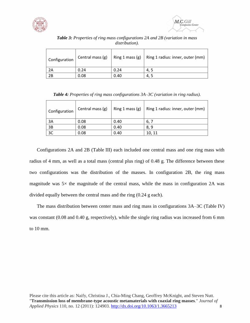
Table 3: Properties of ring mass configurations 2A and 2B (variation in mass
distribution).
Configuration
Central mass (g)
Ring 1 mass (g)
Ring 1 radius: inner, outer (mm)
2A 0.24 0.24 4, 5
2B 0.08 0.40 4, 5
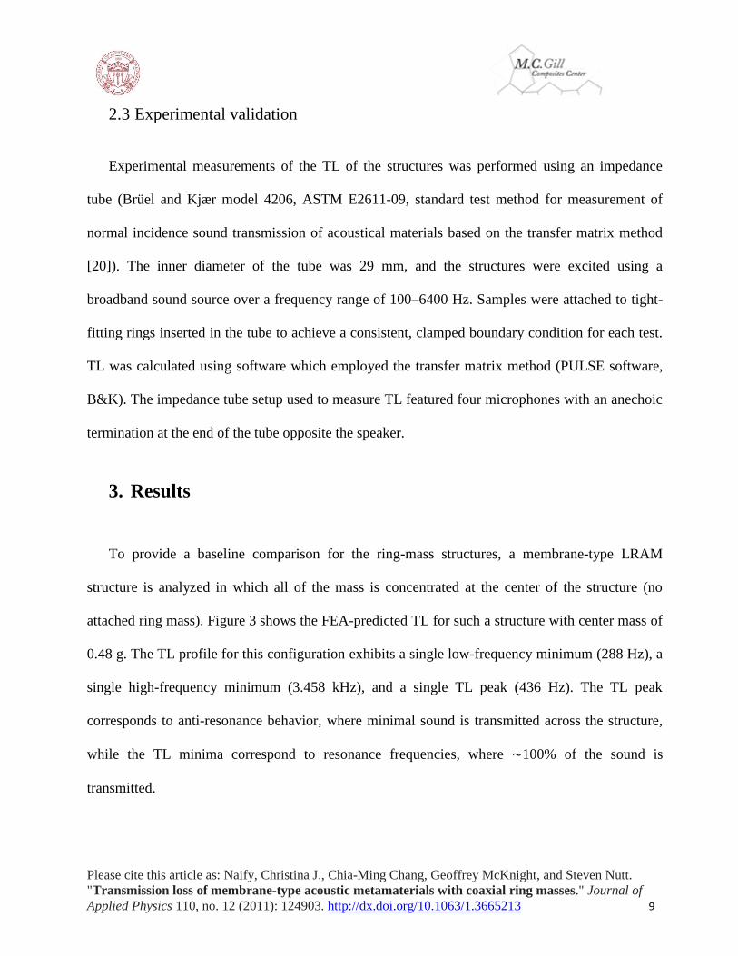
Table 4: Properties of ring mass configurations 3A–3C (variation in ring radius).
Configuration
Central mass (g)
Ring 1 mass (g)
Ring 1 radius: inner, outer (mm)
3A 0.08 0.40 6, 7
3B 0.08 0.40 8, 9
3C 0.08 0.40 10, 11
Configurations 2A and 2B (Table III) each included one central mass and one ring mass with
radius of 4 mm, as well as a total mass (central plus ring) of 0.48 g. The difference between these
two configurations was the distribution of the masses. In configuration 2B, the ring mass
magnitude was 5× the magnitude of the central mass, while the mass in configuration 2A was
divided equally between the central mass and the ring (0.24 g each).
The mass distribution between center mass and ring mass in configurations 3A–3C (Table IV)
was constant (0.08 and 0.40 g, respectively), while the single ring radius was increased from 6 mm
to 10 mm.
Please cite this article as: Naify, Christina J., Chia-Ming Chang, Geoffrey McKnight, and Steven Nutt.
"Transmission loss of membrane-type acoustic metamaterials with coaxial ring masses." Journal of
Applied Physics 110, no. 12 (2011): 124903. http://dx.doi.org/10.1063/1.3665213 9
2.3 Experimental validation
Experimental measurements of the TL of the structures was performed using an impedance
tube (Brüel and Kjær model 4206, ASTM E2611-09, standard test method for measurement of
normal incidence sound transmission of acoustical materials based on the transfer matrix method
[20]). The inner diameter of the tube was 29 mm, and the structures were excited using a
broadband sound source over a frequency range of 100–6400 Hz. Samples were attached to tight-
fitting rings inserted in the tube to achieve a consistent, clamped boundary condition for each test.
TL was calculated using software which employed the transfer matrix method (PULSE software,
B&K). The impedance tube setup used to measure TL featured four microphones with an anechoic
termination at the end of the tube opposite the speaker.
3. Results
To provide a baseline comparison for the ring-mass structures, a membrane-type LRAM
structure is analyzed in which all of the mass is concentrated at the center of the structure (no
attached ring mass). Figure 3 shows the FEA-predicted TL for such a structure with center mass of
0.48 g. The TL profile for this configuration exhibits a single low-frequency minimum (288 Hz), a
single high-frequency minimum (3.458 kHz), and a single TL peak (436 Hz). The TL peak
corresponds to anti-resonance behavior, where minimal sound is transmitted across the structure,
while the TL minima correspond to resonance frequencies, where ∼100% of the sound is
transmitted.

Please cite this article as: Naify, Christina J., Chia-Ming Chang, Geoffrey McKnight, and Steven Nutt.
"Transmission loss of membrane-type acoustic metamaterials with coaxial ring masses." Journal of
Applied Physics 110, no. 12 (2011): 124903. http://dx.doi.org/10.1063/1.3665213 10
Figure 3: FEA-predicted TL of a structure with 0.48 g mass in center (no attached ring
mass).
As presented in previous studies [9], the frequency of the first resonance was dominated by
center mass magnitude along with membrane tension, while the second resonance frequency was
dominated by membrane mass and thickness. The frequency of the TL peak was tuned by varying
both membrane and mass properties. Increasing the magnitude of the mass resulted in a decrease in
TL peak frequency, while decreasing the membrane radius resulted in an increase in TL peak and
resonance frequencies.
Figure 4(a) shows FEA results of predicted TL for two additional structures. The first had a
central mass of 0.16 g (configuration 1A), while the second had no central mass, but instead only a
ring mass of radius 4 mm and mass 0.16 g (configuration 1B). The combination of these two mass
distributions formed the distribution in configuration 1C. The TL profiles of configurations 1A and
1B each show a single TL peak and two resonance dips. The frequencies of the peak and resonance
dips for configurations 1A and 1B are shown in Table V along with those of configuration 1C.
Additionally, acoustic mass law-predicted TL behavior is shown in Fig. 4(a) for a single partition

Please cite this article as: Naify, Christina J., Chia-Ming Chang, Geoffrey McKnight, and Steven Nutt.
"Transmission loss of membrane-type acoustic metamaterials with coaxial ring masses." Journal of
Applied Physics 110, no. 12 (2011): 124903. http://dx.doi.org/10.1063/1.3665213 11
structure with surface density equivalent to that of configuration 1A, 1B (0.16 g added to the
membrane), and configuration 1C (0.32 g added to the membrane). The acoustic mass law TL was
calculated using Eq. (3) [21]
(3)
where ω = 2πf, f is the frequency, ρs is the surface density of the samples (density per unit
thickness), and ρo and c are the density and speed of sound in the surrounding fluid (air),
respectively. The TL peak for configuration 1A increased 56 dB over the mass law prediction,
while the TL peak for configuration 1B increased 46 dB. The TL peak magnitudes for
configuration 1C were 36 dB and 49 dB above the mass law prediction.
Figure 4: (Color online) a) FEA results showing TL of configurations 1A (central mass
only), 1B (ring mass only), and 1C (central mass and one ring mass) as well as acoustic
mass law-predicted TL. b) FEA showing TL of configurations 1C (central mass and one
ring mass), 1D (central mass and two ring masses), and 1E (central mass and three ring
masses).
Please cite this article as: Naify, Christina J., Chia-Ming Chang, Geoffrey McKnight, and Steven Nutt.
"Transmission loss of membrane-type acoustic metamaterials with coaxial ring masses." Journal of
Applied Physics 110, no. 12 (2011): 124903. http://dx.doi.org/10.1063/1.3665213 12
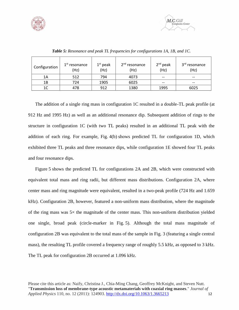
Table 5: Resonance and peak TL frequencies for configurations 1A, 1B, and 1C.
Configuration
1st resonance
(Hz)
1st peak
(Hz)
2nd resonance
(Hz)
2nd peak
(Hz)
3rd resonance
(Hz)
1A 512 794 4073 -- --
1B 724 1905 6025 -- --
1C 478 912 1380 1995 6025
The addition of a single ring mass in configuration 1C resulted in a double-TL peak profile (at
912 Hz and 1995 Hz) as well as an additional resonance dip. Subsequent addition of rings to the
structure in configuration 1C (with two TL peaks) resulted in an additional TL peak with the
addition of each ring. For example, Fig. 4(b) shows predicted TL for configuration 1D, which
exhibited three TL peaks and three resonance dips, while configuration 1E showed four TL peaks
and four resonance dips.
Figure 5 shows the predicted TL for configurations 2A and 2B, which were constructed with
equivalent total mass and ring radii, but different mass distributions. Configuration 2A, where
center mass and ring magnitude were equivalent, resulted in a two-peak profile (724 Hz and 1.659
kHz). Configuration 2B, however, featured a non-uniform mass distribution, where the magnitude
of the ring mass was 5× the magnitude of the center mass. This non-uniform distribution yielded
one single, broad peak (circle-marker in Fig. 5). Although the total mass magnitude of
configuration 2B was equivalent to the total mass of the sample in Fig. 3 (featuring a single central
mass), the resulting TL profile covered a frequency range of roughly 5.5 kHz, as opposed to 3 kHz.
The TL peak for configuration 2B occurred at 1.096 kHz.

Please cite this article as: Naify, Christina J., Chia-Ming Chang, Geoffrey McKnight, and Steven Nutt.
"Transmission loss of membrane-type acoustic metamaterials with coaxial ring masses." Journal of
Applied Physics 110, no. 12 (2011): 124903. http://dx.doi.org/10.1063/1.3665213 13
Figure 5: (Color online) FEA-predicted TL of configurations 2A (uniform mass
distribution) and 2B (non-uniform mass distribution).
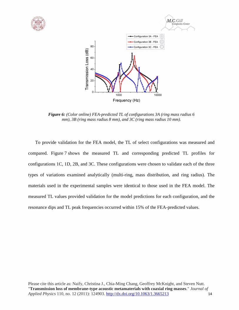
Figure 6 shows the effect of ring diameter on TL using configurations 3(A-C). Configuration
3A displayed a wide-band, two-peak profile with a frequency span of almost 10 kHz. As the radius
of the ring was further increased, the wide-band behavior diminished, and despite the non-uniform
mass distribution, a resonance dip appeared between the two TL peaks. Demonstrating this, the TL
behavior of configuration 3C, in which the ring mass radius was 10 mm, had a frequency
bandwidth of only about 2.5 kHz.
Please cite this article as: Naify, Christina J., Chia-Ming Chang, Geoffrey McKnight, and Steven Nutt.
"Transmission loss of membrane-type acoustic metamaterials with coaxial ring masses." Journal of
Applied Physics 110, no. 12 (2011): 124903. http://dx.doi.org/10.1063/1.3665213 14
Figure 6: (Color online) FEA-predicted TL of configurations 3A (ring mass radius 6
mm), 3B (ring mass radius 8 mm), and 3C (ring mass radius 10 mm).
To provide validation for the FEA model, the TL of select configurations was measured and
compared. Figure 7 shows the measured TL and corresponding predicted TL profiles for
configurations 1C, 1D, 2B, and 3C. These configurations were chosen to validate each of the three
types of variations examined analytically (multi-ring, mass distribution, and ring radius). The
materials used in the experimental samples were identical to those used in the FEA model. The
measured TL values provided validation for the model predictions for each configuration, and the
resonance dips and TL peak frequencies occurred within 15% of the FEA-predicted values.

Please cite this article as: Naify, Christina J., Chia-Ming Chang, Geoffrey McKnight, and Steven Nutt.
"Transmission loss of membrane-type acoustic metamaterials with coaxial ring masses." Journal of
Applied Physics 110, no. 12 (2011): 124903. http://dx.doi.org/10.1063/1.3665213 15
Figure 7: (Color online) FEA-predicted (dashed) and experimental (triangle) TL
profiles for a) configuration 1C (uniform mass distribution), b) configuration 1D
(multiple rings, central mass, and two ring masses), c) configuration 2B (non-uniform
mass distribution), and d) configuration 3C (ring radius variation, radius of 10 mm).
4. Discussion
The circular membrane with a single central mass exhibited both high-order resonance and
anti-resonance behavior, as expected, although the frequencies of these anti-resonances (TL peaks)
occurred well above the membrane resonance frequency. Variations in membrane properties, such
as membrane tension, thickness, or radius, shifted the anti-resonance peak frequencies, much like
they did the low frequency TL peaks [9]. However, the shifts were relatively small, and it was not
possible to reduce the anti-resonance peaks to below the membrane resonance simply by varying

Please cite this article as: Naify, Christina J., Chia-Ming Chang, Geoffrey McKnight, and Steven Nutt.
"Transmission loss of membrane-type acoustic metamaterials with coaxial ring masses." Journal of
Applied Physics 110, no. 12 (2011): 124903. http://dx.doi.org/10.1063/1.3665213 16
membrane properties. Additionally, variations in the membrane properties to tune high-frequency
anti-resonances could have the adverse effect of de-tuning lower frequency TL peaks. Because of
the constraints involved in tuning anti-resonance TL peaks by varying membrane properties,
implementation of ring masses afforded an appealing means of generating multi-peak TL profiles
at low frequencies. Note, however, that despite the creation of multi-peak TL profiles, some
drawbacks are associated with the use of ring masses. In particular, the addition of the ring mass
(configuration 1C) resulted in an increase in the overall mass of the structure compared to a
structure with no ring mass (configuration 1A). Nevertheless, despite an overall increase in mass,
TL peak increase over the mass law-predicted TL for a structure with 0.32 g central mass [9, 21]
was 36 dB at the low frequency peak.
FEA predictions of TL for a membrane-type LRAM were presented and compared to
experimentally obtained values. A single cell of LRAM with mass concentrated at the membrane
center produced a one-peak TL profile with narrow bandwidth (3.5 kHz, Fig. 3). The addition of
an annular ring mass with mass equivalent to the center mass resulted in multiple TL peaks, with a
distinct peak present for each ring added. Variations of the ring geometry (mass and radius) as well
as the distribution of mass between the center mass and ring resulted in distinctly different TL
profiles.
Analysis of configurations 1A (center mass only) and 1B (ring mass only) was included to
provide comparison with configuration 1C (center mass and ring mass). Configuration 1A and 1B
both displayed a single TL peak with frequency values similar to those of each of the two peaks in
configuration 1C (Fig. 4(a)). The difference in TL peak frequencies between configurations 1A
and 1B and configuration 1C was due to the combined effects of an increased mass magnitude and
Please cite this article as: Naify, Christina J., Chia-Ming Chang, Geoffrey McKnight, and Steven Nutt.
"Transmission loss of membrane-type acoustic metamaterials with coaxial ring masses." Journal of
Applied Physics 110, no. 12 (2011): 124903. http://dx.doi.org/10.1063/1.3665213 17
a decrease in membrane radius between the masses and the support ring. The increase in overall
applied mass magnitude (from 0.16 g in configurations 1A and 1B to 0.32 g in configuration 1C)
caused the frequency of the first resonance to decrease. The high-frequency resonance (6.025
kHz), which was dependent on membrane properties, was equal in magnitude for configurations
1B and 1C because of the equal distance between the ring mass and the support ring (8 mm).
In configurations 1C-E, up to three rings were added to the structure. The radii of the rings
were evenly distributed across the radius of the membrane. The resulting TL profile for a three-
ring (plus central mass) structure exhibited four distinct TL peaks (Fig. 4(b)). Although the overall
mass of the structure increased with the addition of each ring, the number of TL peaks also
increased. The first resonance frequencies of configurations 1C-E were 478 Hz, 549 Hz, and 630
Hz, respectively. The variation in frequency was due to the dependence of the first resonance
frequency on center mass magnitude. As more mass was concentrated away from the center of the
structure with increasing ring additions, the first resonance frequency also increased.
The effect of mass distribution uniformity was examined in configurations 2A and 2B. A
uniform mass distribution between the center mass and the single ring (configuration 2A, Fig. 5)
resulted in a two-peak TL profile. The first TL peak corresponded to the anti-resonance dominated
by the center mass, while the second TL peak corresponded to the anti-resonance dominated by the
ring mass. The mass was redistributed in configuration 2B so that the mass of the ring was 5× that
of the center mass, and, as a result, the two TL peaks moved closer together. The ring mass TL
peak decreased and the central mass TL peak increased, eventually resulting in a single, wide-band
peak. Although the single TL peak in configuration 2B showed a wider frequency bandwidth than
the sample in Fig. 3 (single central mass), the TL peak also occurred at higher frequency (1148 Hz

Please cite this article as: Naify, Christina J., Chia-Ming Chang, Geoffrey McKnight, and Steven Nutt.
"Transmission loss of membrane-type acoustic metamaterials with coaxial ring masses." Journal of
Applied Physics 110, no. 12 (2011): 124903. http://dx.doi.org/10.1063/1.3665213 18
versus 436 Hz). Thus, a trade-off arises between creating a wide-band peak and achieving a large
TL magnitude (over 40 dB) at low frequencies. A wide-band TL peak at low frequencies can be
obtained either by increasing the mass magnitude of the central and ring masses or by varying the
membrane properties. For example, a decrease in membrane tension resulted in a decrease in TL
peak frequency [9]. Other geometric variations, such as decrease in membrane thickness and
increase in membrane radius, can also be employed to achieve TL peaks at low frequencies.
Structure geometries and mass distributions can be altered to achieve a desired TL outcome (multi-
peak, single peak), and these geometries can be designed and optimized using FEA.
Improvements in sound insulation resulting from the addition of ring masses can be quantified
by examining the frequency bandwidth of the TL peak. The bandwidth of the TL peak (resonance-
to-resonance) for the structure with a 0.48 g center mass (Fig. 3) was 3.2 kHz. Adding a ring mass
and using the mass distribution of configuration 2B (Fig. 5) increased the frequency bandwidth to
5.5 kHz, an increase of 72%, with no change in the structure mass. The width of the TL peak at a
sound level of 30 dB for the 0.48 center mass structure was ∼ 300 Hz, while the width of the TL
peak for configuration 2B was 1.4 kHz, an increase of 366%.
Increasing the ring mass radius to 6 mm (as in configuration 3A, Fig. 6) resulted in an increase
in the frequency band of the TL peak (8.5 kHz). As the radius was further increased to 8 mm and
10 mm, a resonance dip was introduced, and a narrowing of the TL peak frequency band occurred.
As the ring diameter approached the radius of the cell, the effect of the ring was diminished. The
increase in ring diameter resulted in a structure whose behavior approached that of a cell with a
central mass and a smaller overall membrane radius. When a single mass was concentrated at the

Please cite this article as: Naify, Christina J., Chia-Ming Chang, Geoffrey McKnight, and Steven Nutt.
"Transmission loss of membrane-type acoustic metamaterials with coaxial ring masses." Journal of
Applied Physics 110, no. 12 (2011): 124903. http://dx.doi.org/10.1063/1.3665213 19
membrane center, the structure displayed a large TL peak, although the width of the peak was
narrow (100 Hz).
To better understand the behavior of the structures under excitation, FEA was used to predict
resonant and anti-resonant mode shapes at discrete frequencies (Fig. 8(b)). The frequencies
selected for the mode shape calculations were those of each TL peak and resonant frequency for
configuration 2A (see Fig. 5). General mode shapes for configuration 2A are shown in Fig. 8(b)
along with a schematic of the setup and qualitative phase information about the motion of the
central mass m1 relative to the ring mass m2. Displacements were also measured using a laser
vibrometer. The vibrometer measured out-of-plane displacements at 20 points swept radially
across the structure, which was excited at discrete frequencies using the impedance tube speaker
(experimental setup is detailed in Naify et al. [9]). Mode shapes measured experimentally are
shown in Fig. 8(d).

Please cite this article as: Naify, Christina J., Chia-Ming Chang, Geoffrey McKnight, and Steven Nutt.
"Transmission loss of membrane-type acoustic metamaterials with coaxial ring masses." Journal of
Applied Physics 110, no. 12 (2011): 124903. http://dx.doi.org/10.1063/1.3665213 20
Figure 7: (Color online) a) Schematic showing masses, membrane, and support ring. b)
Displacement profile (FEA) of the motion of the structure with configuration 2A
(uniform mass distribution) for the three resonance and two peak frequencies. Light
gray – component displacement up, dark gray – component displacement down, black –
no displacement. Arrows indicate points of inflection of the membrane across the
neutral axis (corresponding to no displacement). c) Measured out-of-plane
displacement profile of structure with configuration 2A.

Please cite this article as: Naify, Christina J., Chia-Ming Chang, Geoffrey McKnight, and Steven Nutt.
"Transmission loss of membrane-type acoustic metamaterials with coaxial ring masses." Journal of
Applied Physics 110, no. 12 (2011): 124903. http://dx.doi.org/10.1063/1.3665213 21
At the first resonance dip of the structure (416 Hz), m1 and m2 vibrated in-phase, and there was
no inflection point in the membrane. This behavior was consistent with the first resonance of a
structure in which all of the mass is concentrated at the membrane center (no ring mass). The mode
shape of the first TL peak (870 Hz) was also consistent with single-mass (no ring mass) behavior
in that both m1 and m2 were in-phase and the membrane showed an inflection point across the
neutral axis. Explanation of the relationship between this mode shape and the high-magnitude TL
at the given frequency has been documented in previous studies [9].
The dynamic response of the structure at the second resonance dip, which occurred between
the two TL peaks (1150 Hz), showed m1 and m2 were mutually out-of-phase, and, although an
inflection point occurred between the two masses, there was no inflection between the masses and
the support ring. At the second TL peak (1450 Hz), m1 and m2 were mutually out-of-phase,
although the inflection point between the masses and the support ring also appeared at a radius
similar to the inflection point at the first TL peak frequency. Finally, at the third resonance dip
(6020 Hz), both the central mass (m1) and the ring mass m2 were stationary, while the membrane
showed a displacement maximum. This behavior was consistent with the single-mass (no ring
mass) behavior shown previously (Fig. 3). Out-of-plane displacement measured experimentally
matched FEA-predicted mode shapes in the general shape of the structure under single-frequency
excitation.
Experimental measurements of TL provided validation of the accuracy of the predicted TL for
each of the compared configurations. Minor discrepancies between the experimental and FEA TL
values arose because of sample construction variables and simplifications or assumptions made in
Please cite this article as: Naify, Christina J., Chia-Ming Chang, Geoffrey McKnight, and Steven Nutt.
"Transmission loss of membrane-type acoustic metamaterials with coaxial ring masses." Journal of
Applied Physics 110, no. 12 (2011): 124903. http://dx.doi.org/10.1063/1.3665213 22
the model (e.g., no damping). Some of the imperfections in sample construction leading to error
included positioning both the central mass and positioning ring masses to be concentric with the
support ring. The fabrication technique for the ring masses resulted in the inner and outer
diameters of the ring not being perfectly concentric.
The FEA over-predicted the magnitude of the TL peaks, and this was attributed primarily to
the exclusion of damping from the analysis. Additionally, a perfectly clamped boundary condition
was used in the model, as well as a calculated tension value, both of which could cause deviations
from measured TL profiles. Although the FEA model used yielded reasonably accurate predictions
of the measured TL profile for the single-celled axisymmetric samples, more samples with more
complex geometry, such as a multi-celled array or square cells (where axisymmetric models would
not be used) will present greater computational challenges. Although increased complexity is
likely to result in larger discrepancies between predicted and measured values, this analytical
approach should be useful for predicting overall trends in performance for membrane-type LRAMs
with attached ring masses.
5. Conclusions
Membrane-type LRAMs with ring masses were fabricated and evaluated to determine the
effects of ring geometry on the TL performance of the structures. FEA was performed on the
structure to determine favorable geometries with the goals of achieving broadband sound
insulation and/or a multi-peak TL profile from a single cell. Once desired geometries were
achieved, experimental validation was undertaken to confirm the accuracy of the predictive
capabilities of the model.
Please cite this article as: Naify, Christina J., Chia-Ming Chang, Geoffrey McKnight, and Steven Nutt.
"Transmission loss of membrane-type acoustic metamaterials with coaxial ring masses." Journal of
Applied Physics 110, no. 12 (2011): 124903. http://dx.doi.org/10.1063/1.3665213 23
Multiple ring configurations were analyzed with three major types of variation: the number of
rings, the mass distribution, and the ring radii. Increasing the number of rings attached to the
sample resulted in a multi-peak TL profile, in which the number of additional peaks corresponded
to the number of attached rings. Variations in the uniformity of the mass distributed between the
central mass and ring mass resulted in either a multi-peak profile (uniform mass) or a broadband
TL peak (non-uniform mass). Increasing the radius of the ring to approach the membrane radius
had a counterproductive effect on the TL performance, decreasing the TL bandwidth.
The addition of ring masses to a membrane-type LRAM proved effective in both increasing the
frequency bandwidth of the TL peak and attaining multiple TL peaks from a single cell. In
contrast, previous reports had shown that acoustic metamaterials attenuated sound waves over only
a narrow frequency range. The results presented here demonstrate that the effectiveness of this
type of membrane-type structure can be extended to a broad frequency range (from 3.2 kHz to 5.5
kHz) using only a single cell and, thus, the use of multiple layers of LRAMs (the approach
currently used for broadband insulation) may not be necessary. The use of a single layer of LRAM,
in turn, would offer both weight and space-savings in the design of the structure, critical
parameters for aerospace and automotive applications. The addition of multiple ring masses to a
cell is an approach well-suited to applications in which multiple tones require attenuation. TL
profiles for various sound insulation needs are thus achievable by geometric variation of the
membrane-type LRAM structure without addition of mass.
Acknowledgements: The authors would like to thank HRL Laboratories for support of this work.
The authors would also like to thank Matt Sneddon for technical support and Ryan van
Schilfgaarde for assistance with sample preparation.

Please cite this article as: Naify, Christina J., Chia-Ming Chang, Geoffrey McKnight, and Steven Nutt.
"Transmission loss of membrane-type acoustic metamaterials with coaxial ring masses." Journal of
Applied Physics 110, no. 12 (2011): 124903. http://dx.doi.org/10.1063/1.3665213 24
References:
1. Z. Kin, M. H. Huang, X. X. Zhang, and P. Sheng, Appl. Acoust. 66, 751
(2005).http://dx.doi.org/10.1016/j.apacoust.2004.11.005
2. N. Fang, H. Lee, C. Sun, and X. Zhang, Science 22, 534
(2005).http://dx.doi.org/10.1126/science.1108759
3. M. Hirsekorn, Appl. Phys. Lett. 84(17), 3364 (2004).http://dx.doi.org/10.1063/1.1723688
4. J. Li and C. T. Chan, Phys. Rev. E 70, 055602
(2004).http://dx.doi.org/10.1103/PhysRevE.70.055602
5. M. H. Lu, L. Feng, and Y. F. Chen, Mater. Today 12, 34 (2009).http://dx.doi.org/10.1016/S1369-
7021(09)70315-3
6. K. M. Ho, C. K. Cheng, Z. Yang, X. X. Zhang, P. Sheng, X. X. Zhang, Z. Liu, and C. T.
Chan, Appl. Phys. Lett. 83(26), 5566 (2003).http://dx.doi.org/10.1063/1.1637152
7. Z. Liu, X. Zhang, Y. Mao, Z. Yang, C. T. Chan, and P. Sheng, Science 289, 1734
(2000).http://dx.doi.org/10.1126/science.289.5485.1734
8. Z. Yang, J. Mei, M. Yang, N. H. Chan, and P. Sheng, Phys. Rev. Lett. 101, 204301
(2008).http://dx.doi.org/10.1103/PhysRevLett.101.204301
9. C. J. Naify, C. M. Chang, G. McKnight, and S. Nutt, J. Appl. Phys. 108(11), 114905
(2010).http://dx.doi.org/10.1063/1.3514082
10. C. J. Naify, C. M. Chang, G. McKnight, F. Scheulen, and S. R. Nutt, J. Appl. Phys. 109, 104902
(2011).http://dx.doi.org/10.1063/1.3583656
11. Z. Yang, H. M. Dai, N. H. Chan, G. C. Ma, and P. Sheng, Appl. Phys. Lett. 96, 041906
(2010).http://dx.doi.org/10.1063/1.3299007
12. M. Hirsekorn, P. P. Delsanto, N. K. Batra, and P. Matic, Ultrasonics 42, 231
(2004).http://dx.doi.org/10.1016/j.ultras.2004.01.014
13. X. Zhou and G. Hu, Phys. Rev. B 79, 195109
(2009).http://dx.doi.org/10.1103/PhysRevB.79.195109
14. C. Goffaux and J. Sanchez-Dehesa, Phys. Rev. B 67, 144301
(2003).http://dx.doi.org/10.1103/PhysRevB.67.144301
15. M. Hirsekorn, P. P. Delsanto, A. C. Leung, and P. Matic, J. Appl. Phys. 99, 124912
(2006).http://dx.doi.org/10.1063/1.2208528
16. Y. Gu, X. Luo, and H. Ma, J. Appl. Phys. 105, 044903 (2009).http://dx.doi.org/10.1063/1.3075820
17. H. Zhao, J. Wen, D. Yu, and X. Wen, J. Appl. Phys. 107, 023519
(2010).http://dx.doi.org/10.1063/1.3284943
18. H. Larabi, Y. Pennec, B. Djafari-Rouhani, and J. O. Vasseur, Phys. Rev. E 75, 066601
(2007).http://dx.doi.org/10.1103/PhysRevE.75.066601
19. K. T. Wan, S. Guo, and D. Dillard, Thin Solid Films 425, 150
(2003).http://dx.doi.org/10.1016/S0040-6090(02)01103-3
20. ASTM-Standard Test Method for Measurement of Normal Incidence Sound Transmission of
Acoustical Materials Based on the Transfer Matrix Method (ASTM, West Conshohocken, USA,
2009).
21. L. E. Kinsler, A. R. Frey, A. B. Coppens, and J. V. Sanders, Fundamental of Acoustics (Wiley,
New York, 2000), Vol. 4.