TRANSMISSION & DRIVELINE FAX A - Infiniti club · TRANSMISSION & DRIVELINE C E ... Ball joint...
36
FAX-1 TRANSMISSION & DRIVELINE C E F G H I J K L M SECTION FAX A B FAX N O P CONTENTS FRONT AXLE 2WD SYMPTOM DIAGNOSIS .............................. 3 NOISE, VIBRATION AND HARSHNESS (NVH) TROUBLESHOOTING ............................ 3 NVH Troubleshooting Chart ..................................... 3 PREPARATION ........................................... 4 PREPARATION .................................................. 4 Commercial Service Tool ......................................... 4 PERIODIC MAINTENANCE ......................... 5 FRONT WHEEL HUB AND KNUCKLE ............. 5 Inspection ................................................................. 5 REMOVAL AND INSTALLATION ............... 6 FRONT WHEEL HUB AND KNUCKLE ............. 6 Exploded View ......................................................... 6 Removal and Installation .......................................... 6 Inspection ................................................................. 7 SERVICE DATA AND SPECIFICATIONS (SDS) ............................................................ 8 SERVICE DATA AND SPECIFICATIONS (SDS) .................................................................. 8 Wheel Bearing .......................................................... 8 AWD SYMPTOM DIAGNOSIS .............................. 9 NOISE, VIBRATION AND HARSHNESS (NVH) TROUBLESHOOTING ............................ 9 NVH Troubleshooting Chart ..................................... 9 PRECAUTION ............................................. 10 PRECAUTIONS .................................................10 Precaution for Supplemental Restraint System (SRS) "AIR BAG" and "SEAT BELT PRE-TEN- SIONER" ................................................................10 Precaution Necessary for Steering Wheel Rota- tion after Battery Disconnect ..................................10 Precautions for Drive Shaft .....................................11 PREPARATION .......................................... 12 PREPARATION ................................................. 12 Special Service Tool ...............................................12 Commercial Service Tool .......................................13 PERIODIC MAINTENANCE ....................... 14 FRONT WHEEL HUB AND KNUCKLE ............ 14 Inspection ...............................................................14 FRONT DRIVE SHAFT ..................................... 15 Inspection ...............................................................15 REMOVAL AND INSTALLATION .............. 16 FRONT WHEEL HUB AND KNUCKLE ............ 16 Exploded View ........................................................16 Removal and Installation ........................................16 Inspection ...............................................................17 FRONT DRIVE SHAFT BOOT .......................... 18 Exploded View ........................................................18 WHEEL SIDE ............................................................19 WHEEL SIDE : Removal and Installation ...............19 FINAL DRIVE SIDE ...................................................24 FINAL DRIVE SIDE : Removal and Installation ......24 Inspection ...............................................................24 FRONT DRIVE SHAFT ..................................... 26 Exploded View ........................................................26 LEFT SIDE ................................................................27 LEFT SIDE : Removal and Installation ...................27 Revision: 2009 March 2009 FX35/FX50
Transcript of TRANSMISSION & DRIVELINE FAX A - Infiniti club · TRANSMISSION & DRIVELINE C E ... Ball joint...

TRANSMISSION & DRIVELINE
C
E
SECTION FAXA
B
AX
FFRONT AXLE
F
G
H
I
J
K
L
M
N
O
P
CONTENTS
2WD
SYMPTOM DIAGNOSIS ............................... 3
NOISE, VIBRATION AND HARSHNESS (NVH) TROUBLESHOOTING ............................. 3
NVH Troubleshooting Chart ......................................3
PREPARATION ............................................ 4
PREPARATION ................................................... 4Commercial Service Tool ..........................................4
PERIODIC MAINTENANCE .......................... 5
FRONT WHEEL HUB AND KNUCKLE .............. 5Inspection ..................................................................5
REMOVAL AND INSTALLATION ................ 6
FRONT WHEEL HUB AND KNUCKLE .............. 6Exploded View ..........................................................6Removal and Installation ...........................................6Inspection ..................................................................7
SERVICE DATA AND SPECIFICATIONS (SDS) ............................................................. 8
SERVICE DATA AND SPECIFICATIONS (SDS) ................................................................... 8
Wheel Bearing ...........................................................8AWD
SYMPTOM DIAGNOSIS ............................... 9
NOISE, VIBRATION AND HARSHNESS (NVH) TROUBLESHOOTING ............................. 9
NVH Troubleshooting Chart ......................................9
PRECAUTION ..............................................10
PRECAUTIONS ..................................................10
Precaution for Supplemental Restraint System (SRS) "AIR BAG" and "SEAT BELT PRE-TEN-SIONER" .................................................................10Precaution Necessary for Steering Wheel Rota-tion after Battery Disconnect ...................................10Precautions for Drive Shaft ......................................11
PREPARATION ...........................................12
PREPARATION .................................................12Special Service Tool ................................................12Commercial Service Tool ........................................13
PERIODIC MAINTENANCE ........................14
FRONT WHEEL HUB AND KNUCKLE ............14Inspection ................................................................14
FRONT DRIVE SHAFT .....................................15Inspection ................................................................15
REMOVAL AND INSTALLATION ...............16
FRONT WHEEL HUB AND KNUCKLE ............16Exploded View .........................................................16Removal and Installation .........................................16Inspection ................................................................17
FRONT DRIVE SHAFT BOOT ..........................18Exploded View .........................................................18
WHEEL SIDE .............................................................19WHEEL SIDE : Removal and Installation ................19
FINAL DRIVE SIDE ....................................................24FINAL DRIVE SIDE : Removal and Installation .......24Inspection ................................................................24
FRONT DRIVE SHAFT .....................................26Exploded View .........................................................26
LEFT SIDE .................................................................27LEFT SIDE : Removal and Installation ....................27
FAX-1Revision: 2009 March 2009 FX35/FX50

RIGHT SIDE .............................................................. 28RIGHT SIDE : Removal and Installation ................. 28
WHEEL SIDE ............................................................ 29WHEEL SIDE : Disassembly and Assembly ........... 29
FINAL DRIVE SIDE ................................................... 31FINAL DRIVE SIDE : Disassembly and Assembly ... 31Inspection ............................................................... 34
SERVICE DATA AND SPECIFICATIONS (SDS) .......................................................... 36
SERVICE DATA AND SPECIFICATIONS (SDS) ................................................................. 36
Wheel Bearing ........................................................ 36Drive Shaft .............................................................. 36
FAX-2Revision: 2009 March 2009 FX35/FX50

NOISE, VIBRATION AND HARSHNESS (NVH) TROUBLESHOOTING[2WD]
C
E
F
G
H
I
J
K
L
M
A
B
AX
N
O
P
< SYMPTOM DIAGNOSIS >
F
SYMPTOM DIAGNOSISNOISE, VIBRATION AND HARSHNESS (NVH) TROUBLESHOOTING
NVH Troubleshooting Chart INFOID:0000000003858741
Use chart below to find the cause of the symptom. If necessary, repair or replace these parts.
×: Applicable
Reference page
FAX
-6
—
FAX
-5
NV
H in
FA
X a
nd F
SU
sec
tions
NV
H in
WT
sec
tion
NV
H in
WT
sec
tion
Ref
er to
DR
IVE
SH
AF
T in
this
cha
rt.
NV
H in
BR
sec
tion
NV
H in
ST
sec
tion
Possible cause and SUSPECTED PARTS
Impr
oper
inst
alla
tion,
loos
enes
s
Par
ts in
terf
eren
ce
Whe
el b
earin
g da
mag
e
FR
ON
T A
XLE
AN
D F
RO
NT
SU
SP
EN
SIO
N
TIR
E
RO
AD
WH
EE
L
DR
IVE
SH
AF
T
BR
AK
E
ST
EE
RIN
G
Symptom FRONT AXLE
Noise × × × × × × × × ×
Shake × × × × × × × × ×
Vibration × × × × × × ×
Shimmy × × × × × × ×
Judder × × × × × ×
Poor quality ride or handling × × × × ×
FAX-3Revision: 2009 March 2009 FX35/FX50

[2WD]PREPARATION
< PREPARATION >
PREPARATIONPREPARATION
Commercial Service Tool INFOID:0000000003858742
Tool name Description
Power tool Loosening bolts and nuts
Ball joint remover Removing ball joint for steering knuckle
PBIC0190E
NT146
FAX-4Revision: 2009 March 2009 FX35/FX50

FRONT WHEEL HUB AND KNUCKLE[2WD]
C
E
F
G
H
I
J
K
L
M
A
B
AX
N
O
P
< PERIODIC MAINTENANCE >
F
PERIODIC MAINTENANCEFRONT WHEEL HUB AND KNUCKLE
Inspection INFOID:0000000003858743
MOUNTING INSPECTIONMake sure that the mounting conditions (looseness, backlash) of each component and component conditions(wear, damage) are normal.
WHEEL BEARING INSPECTION• Move wheel hub and bearing assembly in the axial direction by hand. Make sure there is no looseness of
wheel bearing.
• Rotate wheel hub and make sure there is no unusual noise or other irregular conditions. If there is any ofirregular conditions, replace wheel hub and bearing assembly.
Axial end play : Refer to FAX-8, "Wheel Bearing".
FAX-5Revision: 2009 March 2009 FX35/FX50

[2WD]FRONT WHEEL HUB AND KNUCKLE
< REMOVAL AND INSTALLATION >
REMOVAL AND INSTALLATIONFRONT WHEEL HUB AND KNUCKLE
Exploded View INFOID:0000000003858744
Removal and Installation INFOID:0000000003858745
REMOVAL1. Remove tires with power tool.2. Remove wheel sensor and sensor harness. Refer to BRC-133, "FRONT WHEEL SENSOR : Exploded
View".CAUTION:Never pull on wheel sensor harness.
3. Remove brake hose bracket. Refer to BR-20, "FRONT : Exploded View".4. Remove caliper assembly with power tool. Hang caliper assembly in a place where it will not interfere with
work. Refer to BR-43, "BRAKE CALIPER ASSEMBLY (2 PISTON TYPE) : Exploded View".CAUTION:Never depress brake pedal while brake caliper is removed.
5. Remove disc rotor. Refer to BR-44, "BRAKE CALIPER ASSEMBLY (2 PISTON TYPE) : Removal andInstallation".
6. Remove wheel hub and bearing assembly, and then remove splash guard.7. Remove steering outer socket. Refer to ST-25, "Exploded View".8. Remove cotter pin of transverse link and steering knuckle, and then loosen nut.9. Separate steering knuckle from upper link.10. Separate steering knuckle from transverse link so as not to damage ball joint boot using the ball joint
remover, and remove steering knuckle.CAUTION:Temporarily tighten the nut to prevent damage to threads and to prevent the ball joint removerfrom suddenly coming off.
INSTALLATIONNote the following, and install in the reverse order of the removal.
1. Steering knuckle 2. Ball seat 3. Cotter pin
4. Splash guard 5. Wheel hub and bearing assembly
Refer to GI-4, "Components" for symbols in the figure.
JPDIF0189GB
FAX-6Revision: 2009 March 2009 FX35/FX50

FRONT WHEEL HUB AND KNUCKLE[2WD]
C
E
F
G
H
I
J
K
L
M
A
B
AX
N
O
P
< REMOVAL AND INSTALLATION >
F
• Perform the final tightening of each of parts under unladen conditions, which were removed when removingwheel hub and bearing assembly and steering knuckle.
• Never reuse cotter pin.
Inspection INFOID:0000000003858746
INSPECTION AFTER REMOVALCheck components for deformation, cracks, and other damage. Replace it if necessary.
Ball Joint InspectionCheck boots of transverse link and steering outer socket ball joint for breakage, axial play, and torque. Refer toFSU-13, "Inspection" and ST-33, "Inspection".
INSPECTION AFTER INSTALLATION1. Check wheel sensor harness for proper connection. Refer to BRC-133, "FRONT WHEEL SENSOR :
Exploded View".2. Check the wheel alignment. Refer to FSU-8, "Inspection".3. Adjust neutral position of steering angle sensor. Refer to BRC-9, "ADJUSTMENT OF STEERING ANGLE
SENSOR NEUTRAL POSITION : Special Repair Requirement".
FAX-7Revision: 2009 March 2009 FX35/FX50

[2WD]SERVICE DATA AND SPECIFICATIONS (SDS)
< SERVICE DATA AND SPECIFICATIONS (SDS)
SERVICE DATA AND SPECIFICATIONS (SDS)SERVICE DATA AND SPECIFICATIONS (SDS)
Wheel Bearing INFOID:0000000003858747
Item Standard
Axial end play 0.05 mm (0.002 in) or less
FAX-8Revision: 2009 March 2009 FX35/FX50

NOISE, VIBRATION AND HARSHNESS (NVH) TROUBLESHOOTING[AWD]
C
E
F
G
H
I
J
K
L
M
A
B
AX
N
O
P
< SYMPTOM DIAGNOSIS >
F
SYMPTOM DIAGNOSISNOISE, VIBRATION AND HARSHNESS (NVH) TROUBLESHOOTING
NVH Troubleshooting Chart INFOID:0000000003858748
Use chart below to find the cause of the symptom. If necessary, repair or replace these parts.
×: Applicable
Reference page —
FAX
-34
—
FAX
-16
—
FAX
-14
NV
H in
FA
X a
nd F
SU
sec
tions
Ref
er to
Fro
nt a
xle
in th
is c
hart
.
NV
H in
WT
sec
tion
NV
H in
WT
sec
tion
Ref
er to
DR
IVE
SH
AF
T in
this
cha
rt.
NV
H in
BR
sec
tion
NV
H in
ST
sec
tion
Possible cause and SUSPECTED PARTS
Exc
essi
ve jo
int a
ngle
Join
t slid
ing
resi
stan
ce
Imba
lanc
e
Impr
oper
inst
alla
tion,
loos
enes
s
Par
ts in
terf
eren
ce
Whe
el b
earin
g da
mag
e
FR
ON
T A
XLE
AN
D F
RO
NT
SU
SP
EN
SIO
N
FR
ON
T A
XLE
TIR
E
RO
AD
WH
EE
L
DR
IVE
SH
AF
T
BR
AK
E
ST
EE
RIN
G
Symptom
DRIVE SHAFT
Noise × × × × × × × × ×
Shake × × × × × × × × ×
FRONT AXLE
Noise × × × × × × × × ×
Shake × × × × × × × × ×
Vibration × × × × × × ×
Shimmy × × × × × × ×
Judder × × × × × ×
Poor quality ride or handling × × × × ×
FAX-9Revision: 2009 March 2009 FX35/FX50

[AWD]PRECAUTIONS
< PRECAUTION >
PRECAUTIONPRECAUTIONS
Precaution for Supplemental Restraint System (SRS) "AIR BAG" and "SEAT BELT PRE-TENSIONER" INFOID:0000000004040949
The Supplemental Restraint System such as “AIR BAG” and “SEAT BELT PRE-TENSIONER”, used alongwith a front seat belt, helps to reduce the risk or severity of injury to the driver and front passenger for certaintypes of collision. This system includes seat belt switch inputs and dual stage front air bag modules. The SRSsystem uses the seat belt switches to determine the front air bag deployment, and may only deploy one frontair bag, depending on the severity of a collision and whether the front occupants are belted or unbelted.Information necessary to service the system safely is included in the “SRS AIR BAG” and “SEAT BELT” of thisService Manual.WARNING:• To avoid rendering the SRS inoperative, which could increase the risk of personal injury or death in
the event of a collision which would result in air bag inflation, all maintenance must be performed byan authorized NISSAN/INFINITI dealer.
• Improper maintenance, including incorrect removal and installation of the SRS, can lead to personalinjury caused by unintentional activation of the system. For removal of Spiral Cable and Air BagModule, see the “SRS AIR BAG”.
• Do not use electrical test equipment on any circuit related to the SRS unless instructed to in thisService Manual. SRS wiring harnesses can be identified by yellow and/or orange harnesses or har-ness connectors.
PRECAUTIONS WHEN USING POWER TOOLS (AIR OR ELECTRIC) AND HAMMERSWARNING:• When working near the Air Bag Diagnosis Sensor Unit or other Air Bag System sensors with the
ignition ON or engine running, DO NOT use air or electric power tools or strike near the sensor(s)with a hammer. Heavy vibration could activate the sensor(s) and deploy the air bag(s), possiblycausing serious injury.
• When using air or electric power tools or hammers, always switch the ignition OFF, disconnect thebattery, and wait at least 3 minutes before performing any service.
Precaution Necessary for Steering Wheel Rotation after Battery DisconnectINFOID:0000000004040950
NOTE:• Before removing and installing any control units, first turn the push-button ignition switch to the LOCK posi-
tion, then disconnect both battery cables.• After finishing work, confirm that all control unit connectors are connected properly, then re-connect both
battery cables.• Always use CONSULT-III to perform self-diagnosis as a part of each function inspection after finishing work.
If a DTC is detected, perform trouble diagnosis according to self-diagnosis results.This vehicle is equipped with a push-button ignition switch and a steering lock unit.If the battery is disconnected or discharged, the steering wheel will lock and cannot be turned.If turning the steering wheel is required with the battery disconnected or discharged, follow the procedurebelow before starting the repair operation.
OPERATION PROCEDURE1. Connect both battery cables.
NOTE:Supply power using jumper cables if battery is discharged.
2. Turn the push-button ignition switch to ACC position.(At this time, the steering lock will be released.)
3. Disconnect both battery cables. The steering lock will remain released with both battery cables discon-nected and the steering wheel can be turned.
4. Perform the necessary repair operation.
FAX-10Revision: 2009 March 2009 FX35/FX50

PRECAUTIONS[AWD]
C
E
F
G
H
I
J
K
L
M
A
B
AX
N
O
P
< PRECAUTION >
F
5. When the repair work is completed, re-connect both battery cables. With the brake pedal released, turnthe push-button ignition switch from ACC position to ON position, then to LOCK position. (The steeringwheel will lock when the push-button ignition switch is turned to LOCK position.)
6. Perform self-diagnosis check of all control units using CONSULT-III.
Precautions for Drive Shaft INFOID:0000000003858751
• Observe the following precautions when disassembling and assembling drive shaft.• Never disassemble joint sub-assembly because it is non-overhaul parts.• Perform work in a location which is as dust-free as possible.• Clean the parts, before disassembling and assembling.• Prevent the entry of foreign objects during disassembly of the service location.• Reassemble disassembled parts carefully in the correct order. If work is interrupted, a clean cover must be
placed over parts.• Use paper waste. Fabric shop cloths must not be used because of the danger of lint adhering to parts.• Clean disassembled parts (except for rubber parts) with kerosene which shall be removed by blowing with
air or wiping with paper waste.
FAX-11Revision: 2009 March 2009 FX35/FX50

[AWD]PREPARATION
< PREPARATION >
PREPARATIONPREPARATION
Special Service Tool INFOID:0000000003858752
The actual shapes of Kent-Moore tools may differ from those of special service tools illustrated here.
Tool number (Kent-Moore No.)Tool name
Description
KV40107300( − )Boot band crimping tool
Installing boot band
KV40107500( − )Drive shaft attachment
Removing drive shaft
KV38107900( − )Protectora: 32 mm (1.26 in) dia.
Installing drive shaft
KV38100500( − )Drifta: 80 mm (3.15 in) dia.b: 60 mm (2.36 in) dia.
Installing drive shaft plug
KV38102200( − )Drifta: 90 mm (3.54 in) dia.b: 31 mm (1.22 in) dia.
Installing drive shaft plug
ZZA1229D
ZZA1230D
PDIA1183J
ZZA0701D
ZZA0920D
FAX-12Revision: 2009 March 2009 FX35/FX50

PREPARATION[AWD]
C
E
F
G
H
I
J
K
L
M
A
B
AX
N
O
P
< PREPARATION >
F
Commercial Service Tool INFOID:0000000003858753
Tool name Description
Power tool Loosening bolts and nuts
Ball joint remover Removing ball joint for steering knuckle
Drive shaft puller Removing drive shaft joint sub assembly
Sliding hummer Removing drive shaft
PBIC0190E
NT146
JPDIG0152ZZ
ZZA0023D
FAX-13Revision: 2009 March 2009 FX35/FX50

[AWD]FRONT WHEEL HUB AND KNUCKLE
< PERIODIC MAINTENANCE >
PERIODIC MAINTENANCEFRONT WHEEL HUB AND KNUCKLE
Inspection INFOID:0000000003858754
MOUNTING INSPECTIONMake sure that the mounting conditions (looseness, backlash) of each component and component conditions(wear, damage) are normal.
WHEEL BEARING INSPECTION• Move wheel hub and bearing assembly in the axial direction by hand. Make sure there is no looseness of
wheel bearing.
• Rotate wheel hub and make sure there is no unusual noise or other irregular conditions. If there is any ofirregular conditions, replace wheel hub and bearing assembly.
Axial end play : Refer to FAX-36, "Wheel Bearing".
FAX-14Revision: 2009 March 2009 FX35/FX50

FRONT DRIVE SHAFT[AWD]
C
E
F
G
H
I
J
K
L
M
A
B
AX
N
O
P
< PERIODIC MAINTENANCE >
F
FRONT DRIVE SHAFT
Inspection INFOID:0000000003858755
• Check drive shaft mounting point and joint for looseness and other damage.• Check boot for cracks and other damage.
CAUTION:Replace entire drive shaft assembly when noise or vibration occur from drive shaft.
FAX-15Revision: 2009 March 2009 FX35/FX50

[AWD]FRONT WHEEL HUB AND KNUCKLE
< REMOVAL AND INSTALLATION >
REMOVAL AND INSTALLATIONFRONT WHEEL HUB AND KNUCKLE
Exploded View INFOID:0000000003858756
Removal and Installation INFOID:0000000003858757
REMOVAL1. Remove tires with power tool.2. Remove wheel sensor and sensor harness. Refer to BRC-133, "FRONT WHEEL SENSOR : Exploded
View".CAUTION:Never pull on wheel sensor harness.
3. Remove brake hose bracket. Refer to BR-20, "FRONT : Exploded View".4. Remove caliper assembly with power tool. Hang caliper assembly in a place where it will not interfere with
work. Refer to BR-43, "BRAKE CALIPER ASSEMBLY (2 PISTON TYPE) : Exploded View" (2 piston type),BR-47, "BRAKE CALIPER ASSEMBLY (4 PISTON TYPE) : Exploded View" (4 piston type).CAUTION:Never depress brake pedal while brake caliper is removed.
5. Remove disc rotor. Refer to BR-44, "BRAKE CALIPER ASSEMBLY (2 PISTON TYPE) : Removal andInstallation" (2 piston type), BR-48, "BRAKE CALIPER ASSEMBLY (4 PISTON TYPE) : Removal andInstallation" (4 piston type).
6. Remove cotter pin, and then loosen wheel hub lock nut with power tool.
1. Steering knuckle 2. Ball seat 3. Cotter pin
4. Splash guard 5. Wheel hub and bearing assembly 6. Wheel hub lock nut
Refer to GI-4, "Components" for symbols in the figure.
JPDIF0190GB
FAX-16Revision: 2009 March 2009 FX35/FX50

FRONT WHEEL HUB AND KNUCKLE[AWD]
C
E
F
G
H
I
J
K
L
M
A
B
AX
N
O
P
< REMOVAL AND INSTALLATION >
F
7. Patch wheel hub lock nut with a piece of wood. Hammer thewood to disengage wheel hub and bearing assembly from driveshaft.CAUTION:• Never place drive shaft joint at an extreme angle. Also be
careful not to overextend slide joint.• Never allow drive shaft to hang down without support for
or joint sub-assembly, shaft and the other parts.NOTE:Use suitable puller, if wheel hub and bearing assembly and driveshaft cannot be separated even after performing the above pro-cedure.
8. Remove wheel hub lock nut.9. Remove wheel hub and bearing assembly, and then remove splash guard.10. Remove steering outer socket. Refer to ST-25, "Exploded View".11. Remove cotter pin of transverse link and steering knuckle, and then loosen nut.12. Separate steering knuckle from upper link.13. Separate steering knuckle link from transverse so as not to damage ball joint boot using the ball joint
remover, and remove steering knuckle.CAUTION:Temporarily tighten the nut to prevent damage to threads and to prevent the ball joint removerfrom suddenly coming off.
INSTALLATIONNote the following, and install in the reverse order of the removal.• Perform the final tightening of each of parts under unladen conditions, which were removed when removing
wheel hub and bearing assembly and steering knuckle.• Install drive shaft using tightening torque of wheel hub lock nut. Refer to FAX-16, "Exploded View".
CAUTION:Be sure to use torque wrench to tighten the wheel hub lock nut. Never use a power tool.
• Never reuse cotter pin.
Inspection INFOID:0000000003858758
INSPECTION AFTER REMOVALCheck components for deformation, cracks, and other damage. Replace it if necessary.
Ball Joint InspectionCheck boots of transverse link and steering outer socket ball joint for breakage, axial play, and torque. Refer toFSU-32, "Inspection" and ST-33, "Inspection".
INSPECTION AFTER INSTALLATION1. Check wheel sensor harness for proper connection. Refer to BRC-133, "FRONT WHEEL SENSOR :
Exploded View".2. Check the wheel alignment. Refer to FSU-26, "Inspection".3. Adjust neutral position of steering angle sensor. Refer to BRC-9, "ADJUSTMENT OF STEERING ANGLE
SENSOR NEUTRAL POSITION : Special Repair Requirement".
JPDIG0070ZZ
FAX-17Revision: 2009 March 2009 FX35/FX50

[AWD]FRONT DRIVE SHAFT BOOT
< REMOVAL AND INSTALLATION >
FRONT DRIVE SHAFT BOOT
Exploded View INFOID:0000000003858759
LEFT SIDE
VQ35HR
VK50VE
JPDIF0168GB
1. Joint sub-assembly 2. Circular clip 3. Boot band
4. Boot 5. Shaft 6. Spider assembly
7. Snap ring 8. Housing 9. Plug
: Wheel side
: NISSAN genuine grease or an equivalent.
Refer to GI-4, "Components" for symbols not described on the above.
JPDIF0191GB
1. Joint sub-assembly 2. Circular clip 3. Boot band
4. Boot 5. Shaft 6. Spider assembly
7. Snap ring 8. Housing 9. Plug
: Wheel side
FAX-18Revision: 2009 March 2009 FX35/FX50

FRONT DRIVE SHAFT BOOT[AWD]
C
E
F
G
H
I
J
K
L
M
A
B
AX
N
O
P
< REMOVAL AND INSTALLATION >
F
RIGHT SIDE
WHEEL SIDE
WHEEL SIDE : Removal and Installation INFOID:0000000003858760
REMOVAL
Left Side
1. Remove tires with power tool.2. Remove wheel sensor and sensor harness. Refer to BRC-133, "FRONT WHEEL SENSOR : Exploded
View".CAUTION:Never pull on wheel sensor harness.
3. Remove brake hose bracket. Refer to BR-20, "FRONT : Exploded View".4. Remove caliper assembly mounting bolts with power tool. Hang caliper assembly in a place where it will
not interfere with work. Refer to BR-43, "BRAKE CALIPER ASSEMBLY (2 PISTON TYPE) : ExplodedView" (2 piston type), BR-47, "BRAKE CALIPER ASSEMBLY (4 PISTON TYPE) : Exploded View" (4 pis-ton type).CAUTION:Never depress brake pedal while brake caliper is removed.
5. Remove disc rotor. Refer to BR-44, "BRAKE CALIPER ASSEMBLY (2 PISTON TYPE) : Removal andInstallation" (2 piston type), BR-48, "BRAKE CALIPER ASSEMBLY (4 PISTON TYPE) : Removal andInstallation" (4 piston type).
6. Remove cotter pin, and then loosen wheel hub lock nut with a power tool. Refer to FAX-16, "ExplodedView".
: NISSAN genuine grease or an equivalent.
Refer to GI-4, "Components" for symbols not described on the above.
1. Joint sub-assembly 2. Circular clip 3. Boot band
4. Boot 5. Shaft 6. Spider assembly
7. Snap ring 8. Housing 9. Dust shield
: Wheel side
: NISSAN genuine grease or an equivalent.
Refer to GI-4, "Components" for symbols not described on the above.
JPDIF0197ZZ
FAX-19Revision: 2009 March 2009 FX35/FX50
[AWD]FRONT DRIVE SHAFT BOOT
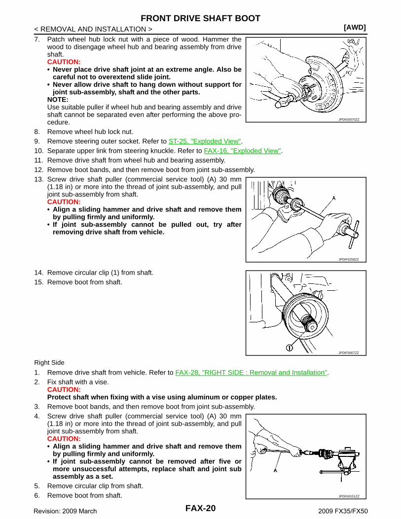
< REMOVAL AND INSTALLATION >7. Patch wheel hub lock nut with a piece of wood. Hammer the
wood to disengage wheel hub and bearing assembly from driveshaft.CAUTION:• Never place drive shaft joint at an extreme angle. Also be
careful not to overextend slide joint.• Never allow drive shaft to hang down without support for
joint sub-assembly, shaft and the other parts.NOTE:Use suitable puller if wheel hub and bearing assembly and driveshaft cannot be separated even after performing the above pro-cedure.
8. Remove wheel hub lock nut.9. Remove steering outer socket. Refer to ST-25, "Exploded View".10. Separate upper link from steering knuckle. Refer to FAX-16, "Exploded View".11. Remove drive shaft from wheel hub and bearing assembly.12. Remove boot bands, and then remove boot from joint sub-assembly.13. Screw drive shaft puller (commercial service tool) (A) 30 mm
(1.18 in) or more into the thread of joint sub-assembly, and pulljoint sub-assembly from shaft.CAUTION:• Align a sliding hammer and drive shaft and remove them
by pulling firmly and uniformly.• If joint sub-assembly cannot be pulled out, try after
removing drive shaft from vehicle.
14. Remove circular clip (1) from shaft.15. Remove boot from shaft.
Right Side
1. Remove drive shaft from vehicle. Refer to FAX-28, "RIGHT SIDE : Removal and Installation".2. Fix shaft with a vise.
CAUTION:Protect shaft when fixing with a vise using aluminum or copper plates.
3. Remove boot bands, and then remove boot from joint sub-assembly.4. Screw drive shaft puller (commercial service tool) (A) 30 mm
(1.18 in) or more into the thread of joint sub-assembly, and pulljoint sub-assembly from shaft.CAUTION:• Align a sliding hammer and drive shaft and remove them
by pulling firmly and uniformly.• If joint sub-assembly cannot be removed after five or
more unsuccessful attempts, replace shaft and joint subassembly as a set.
5. Remove circular clip from shaft.6. Remove boot from shaft.
JPDIG0070ZZ
JPDIF0258ZZ
JPDIF0007ZZ
JPDIG0151ZZ
FAX-20Revision: 2009 March 2009 FX35/FX50

FRONT DRIVE SHAFT BOOT[AWD]
C
E
F
G
H
I
J
K
L
M
A
B
AX
N
O
P
< REMOVAL AND INSTALLATION >
F
INSTALLATION
Left Side
1. Clean the old grease on joint sub-assembly with paper waste.2. Fill serration slot joint sub-assembly (1) with NISSAN genuine
grease or equivalent until the serration slot and ball groovebecome full to the brim.CAUTION:After applying grease, use a shop cloth to wipe off oldgrease that has oozed out.
3. Install boot and boot bands to shaft.CAUTION:• Wrap serration on shaft with tape (A) to protect the boot
from damage.• Never reuse boot and boot band.
4. Remove the tape wrapped around the serration on shaft.
5. Position circular clip (1) on groove at the shaft edge.CAUTION:Never reuse circular clip.NOTE:Drive joint inserter is recommended when installing circular clip.
6. Align both center axles of the shaft edge and joint sub-assembly.Then assemble shaft with joint sub-assembly holding circularclip.
7. Install joint sub-assembly (1) to shaft using plastic hammer.CAUTION:Confirm that joint sub-assembly is correctly engaged whilerotating drive shaft.
8. Apply the specified amount of grease into the boot inside fromlarge diameter side of boot.
JPDIF0008ZZ
JPDIF0009ZZ
JPDIF0010ZZ
Grease amount : Refer to FAX-36, "Drive Shaft".
JPDIF0011ZZ
FAX-21Revision: 2009 March 2009 FX35/FX50

[AWD]FRONT DRIVE SHAFT BOOT
< REMOVAL AND INSTALLATION >9. Install the boot securely into grooves (indicated by “*” marks)
shown in the figure.CAUTION:If grease adheres to the boot mounting surface (indicatedby “*” mark) on the shaft or joint sub-assembly, boot maycome off. Remove all grease from the surface.
10. To prevent the deformation of the boot, adjust the boot installa-tion length (L) to the specified value shown below by insertingthe suitable tool into the inside of the boot from the large diame-ter side of the boot and discharging the inside air.
CAUTION:• If the boot mounting length is outside the standard, it may cause breakage in the boot.• Be careful not to touch the inside of the boot with a tip of tool.
11. Secure the ends of the boot with boot bands using the boot bandcrimping tool (A) [SST: KV40107300 ( − )].CAUTION:Never reuse boot band.
NOTE:Secure boot band so that dimension (M) meets the specificationas shown in the figure.
12. Secure joint sub-assembly and shaft, and then make sure thatthey are in the correct position when rotating boot. Install themwith boot band when boot installation positions become incor-rect.CAUTION:Never reuse boot band.
13. Insert drive shaft to wheel hub and bearing assembly, and thentemporarily tighten wheel hub lock nut.CAUTION:• The drive shaft is press-fit. When assembling the shaft, never press it, but pull it until fully
seated by tightening the wheel hub lock nut.• Check that anticorrosive oil is applied to the thread of the drive shaft. If not, apply appropriate oil
such as engine oil. • If sufficient oil is not applied to the thread of the drive shaft, the wheel hub lock nut may be
seized and the tightening torque reaches the specified limit prematurely. It may cause loosenessor abnormal noises.
14. Install steering knuckle to upper link. Refer to FAX-16, "Exploded View".15. Install steering outer socket to steering knuckle. Refer to ST-25, "Exploded View".16. Tighten the wheel hub lock nut to the specified torque, and install cotter pin. Refer to FAX-16, "Exploded
View".CAUTION:• Be sure to use torque wrench to tighten the wheel hub lock nut. Never use a power tool.• Never reuse cotter pin.• Bend it at the root sufficiently to prevent any looseness.
L : Refer to FAX-36, "Drive Shaft".JPDIF0018ZZ
JPDIF0012ZZ
M : 2.0 – 3.0 mm (0.079 – 0.118 in)
DSF0047D
FAX-22Revision: 2009 March 2009 FX35/FX50

FRONT DRIVE SHAFT BOOT[AWD]
C
E
F
G
H
I
J
K
L
M
A
B
AX
N
O
P
< REMOVAL AND INSTALLATION >
F
17. Install disc rotor. Refer to BR-44, "BRAKE CALIPER ASSEMBLY (2 PISTON TYPE) : Removal and Instal-lation" (2 piston type), BR-48, "BRAKE CALIPER ASSEMBLY (4 PISTON TYPE) : Removal and Installa-tion" (4 piston type).
18. Install caliper assembly to steering knuckle. Refer to BR-43, "BRAKE CALIPER ASSEMBLY (2 PISTONTYPE) : Exploded View" (2 piston type), BR-47, "BRAKE CALIPER ASSEMBLY (4 PISTON TYPE) :Exploded View" (4 piston type).
19. Install brake hose bracket to steering knuckle. Refer to BR-20, "FRONT : Exploded View".20. Install wheel sensor to steering knuckle. Refer to BRC-133, "FRONT WHEEL SENSOR : Exploded View".
Right Side
1. Clean the old grease on joint sub-assembly with paper waste.2. Fill serration slot joint sub-assembly (1) with NISSAN genuine
grease or equivalent until the serration slot and ball groovebecome full to the brim.CAUTION:After applying grease, use a shop cloth to wipe off oldgrease that has oozed out.
3. Install boot and boot bands to shaft.CAUTION:• Wrap serration on shaft with tape (A) to protect the boot
from damage.• Never reuse boot and boot band.
4. Remove the tape wrapped around the serration on shaft.5. Position circular clip on groove at the shaft edge.
CAUTION:Never reuse circular clip.NOTE:Drive joint inserter is recommended when installing circular clip.
6. Align both center axles of the shaft edge and joint sub-assembly.Then assemble shaft with joint sub-assembly holding circular clip.
7. Install joint sub-assembly (1) to shaft using plastic hammer.CAUTION:Confirm that joint sub-assembly is correctly engaged whilerotating drive shaft.
8. Apply the specified amount of grease into the boot inside fromlarge diameter side of boot.
JPDIF0008ZZ
JPDIF0009ZZ
Grease amount : Refer to FAX-36, "Drive Shaft".
JPDIF0011ZZ
FAX-23Revision: 2009 March 2009 FX35/FX50

[AWD]FRONT DRIVE SHAFT BOOT
< REMOVAL AND INSTALLATION >9. Install the boot securely into grooves (indicated by “*” marks)
shown in the figure.CAUTION:If grease adheres to the boot mounting surface (indicatedby “*” mark) on the shaft or joint sub-assembly, boot maycome off. Remove all grease from the surface.
10. To prevent the deformation of the boot, adjust the boot installa-tion length (L) to the specified value shown below by insertingthe suitable tool into inside of the boot from the large diameterside of the boot and discharging the inside air.
CAUTION:• If the boot mounting length is outside the standard, it may cause breakage in the boot.• Be careful not to touch the inside of the boot with a tip of tool.
11. Secure the ends of the boot with boot bands using the boot bandcrimping tool (A) [SST: KV40107300 ( − )].CAUTION:Never reuse boot band.
NOTE:Secure boot band so that dimension (M) meets the specificationas shown in the figure.
12. Secure joint sub-assembly and shaft, and then make sure thatthey are in the correct position when rotating boot. Install themwith boot band when boot installation positions become incor-rect.CAUTION:Never reuse boot band.
13. Install drive shaft to vehicle. Refer to FAX-28, "RIGHT SIDE :Removal and Installation".
FINAL DRIVE SIDE
FINAL DRIVE SIDE : Removal and Installation INFOID:0000000003858761
NOTE:Remove boot after removing drive shaft.• Remove: refer to FAX-27, "LEFT SIDE : Removal and Installation" (left side), FAX-28, "RIGHT SIDE :
Removal and Installation" (right side).• Disassembly: refer to FAX-31, "FINAL DRIVE SIDE : Disassembly and Assembly".
Inspection INFOID:0000000003858762
INSPECTION AFTER REMOVAL• Move joint up/down, left/right, and in the axial directions. Check for motion that is not smooth and for signifi-
cant looseness.
L : Refer to FAX-36, "Drive Shaft".JPDIF0018ZZ
JPDIF0012ZZ
M : 2.0 – 3.0 mm (0.079 – 0.118 in)
DSF0047D
FAX-24Revision: 2009 March 2009 FX35/FX50

FRONT DRIVE SHAFT BOOT[AWD]
C
E
F
G
H
I
J
K
L
M
A
B
AX
N
O
P
< REMOVAL AND INSTALLATION >
F
• Check boot for cracks, damage, and leakage of grease.• Disassemble drive shaft and exchange malfunctioning part if there
is a non-standard condition.
SDIA1163J
FAX-25Revision: 2009 March 2009 FX35/FX50

[AWD]FRONT DRIVE SHAFT
< REMOVAL AND INSTALLATION >
FRONT DRIVE SHAFT
Exploded View INFOID:0000000003858763
LEFT SIDE
VQ35HR
VK50VE
JPDIF0168GB
1. Joint sub-assembly 2. Circular clip 3. Boot band
4. Boot 5. Shaft 6. Spider assembly
7. Snap ring 8. Housing 9. Plug
: Wheel side
: NISSAN genuine grease or an equivalent.
Refer to GI-4, "Components" for symbols not described on the above.
JPDIF0191GB
1. Joint sub-assembly 2. Circular clip 3. Boot band
4. Boot 5. Shaft 6. Spider assembly
7. Snap ring 8. Housing 9. Plug
: Wheel side
FAX-26Revision: 2009 March 2009 FX35/FX50

FRONT DRIVE SHAFT[AWD]
C
E
F
G
H
I
J
K
L
M
A
B
AX
N
O
P
< REMOVAL AND INSTALLATION >
F
RIGHT SIDE
LEFT SIDE
LEFT SIDE : Removal and Installation INFOID:0000000003858764
REMOVAL1. Remove tires with power tool.2. Remove wheel sensor and sensor harness. Refer to BRC-133, "FRONT WHEEL SENSOR : Exploded
View".CAUTION:Never pull on wheel sensor harness.
3. Remove brake hose bracket. Refer to BR-20, "FRONT : Exploded View".4. Remove caliper assembly mounting bolts with power tool. Hang caliper assembly in a place where it will
not interfere with work. Refer to BR-43, "BRAKE CALIPER ASSEMBLY (2 PISTON TYPE) : ExplodedView" (2 piston type), BR-47, "BRAKE CALIPER ASSEMBLY (4 PISTON TYPE) : Exploded View" (4 pis-ton type).CAUTION:Never depress brake pedal while brake caliper is removed.
5. Remove disc rotor. Refer to BR-44, "BRAKE CALIPER ASSEMBLY (2 PISTON TYPE) : Removal andInstallation" (2 piston type), BR-48, "BRAKE CALIPER ASSEMBLY (4 PISTON TYPE) : Removal andInstallation" (4 piston type).
6. Remove cotter pin, and then loosen wheel hub lock nut with a power tool. Refer to FAX-16, "ExplodedView".
: NISSAN genuine grease or an equivalent.
Refer to GI-4, "Components" for symbols not described on the above.
1. Joint sub-assembly 2. Circular clip 3. Boot band
4. Boot 5. Shaft 6. Spider assembly
7. Snap ring 8. Housing 9. Dust shield
: Wheel side
: NISSAN genuine grease or an equivalent.
Refer to GI-4, "Components" for symbols not described on the above.
JPDIF0197ZZ
FAX-27Revision: 2009 March 2009 FX35/FX50

[AWD]FRONT DRIVE SHAFT
< REMOVAL AND INSTALLATION >7. Patch wheel hub lock nut with a piece of wood. Hammer the
wood to disengage wheel hub and bearing assembly from driveshaft.CAUTION:• Never place drive shaft joint at an extreme angle. Also be
careful not to overextend slide joint.• Never allow drive shaft to hang down without support for
joint sub-assembly, shaft and the other parts.NOTE:Use suitable puller if wheel hub and drive shaft cannot be sepa-rated even after performing the above procedure.
8. Remove wheel hub lock nut.9. Remove steering outer socket. Refer to ST-25, "Exploded View".10. Separate upper link from steering knuckle. Refer to FAX-16, "Exploded View".11. Remove drive shaft from wheel hub and bearing assembly.12. Remove shock absorber from vehicle with power tool. Refer to FSU-27, "Exploded View".13. Remove under cover with power tool. Refer to EXT-31, "Exploded View".14. Remove mounting bolts, and then remove drive shaft from the front final drive assembly.
INSTALLATIONNote the following, and install in the reverse order of removal.• Install drive shaft using tightening torque of wheel hub lock nut. Refer to FAX-16, "Exploded View".
CAUTION:Be sure to use torque wrench to tighten the wheel hub lock nut. Never use a power tool.
• Never reuse cotter pin.RIGHT SIDE
RIGHT SIDE : Removal and Installation INFOID:0000000003858765
REMOVAL1. Remove tires with power tool.2. Remove wheel sensor and sensor harness. Refer to BRC-133, "FRONT WHEEL SENSOR : Exploded
View".CAUTION:Never pull on wheel sensor harness.
3. Remove brake hose bracket. Refer to BR-20, "FRONT : Exploded View".4. Remove caliper assembly mounting bolts with power tool. Hang caliper assembly in a place where it will
not interfere with work. Refer to BR-43, "BRAKE CALIPER ASSEMBLY (2 PISTON TYPE) : ExplodedView" (2 piston type), BR-47, "BRAKE CALIPER ASSEMBLY (4 PISTON TYPE) : Exploded View" (4 pis-ton type).CAUTION:Never depress brake pedal while brake caliper is removed.
5. Remove disc rotor. Refer to BR-44, "BRAKE CALIPER ASSEMBLY (2 PISTON TYPE) : Removal andInstallation" (2 piston type), BR-48, "BRAKE CALIPER ASSEMBLY (4 PISTON TYPE) : Removal andInstallation" (4 piston type).
6. Remove cotter pin, and then loosen wheel hub lock nut with a power tool.7. Patch wheel hub lock nut with a piece of wood. Hammer the
wood to disengage wheel hub and bearing assembly from driveshaft.CAUTION:• Never place drive shaft joint at an extreme angle. Also be
careful not to overextend slide joint.• Never allow drive shaft to hang down without support for
joint sub-assembly, shaft and the other parts.NOTE:Use suitable puller if wheel hub and drive shaft cannot be sepa-rated even after performing the above procedure.
JPDIG0070ZZ
JPDIG0070ZZ
FAX-28Revision: 2009 March 2009 FX35/FX50

FRONT DRIVE SHAFT[AWD]
C
E
F
G
H
I
J
K
L
M
A
B
AX
N
O
P
< REMOVAL AND INSTALLATION >
F
8. Remove wheel hub lock nut.9. Remove wheel hub and bearing assembly from steering knuckle. Refer to FAX-16, "Exploded View".10. Remove fender protector. Refer to EXT-25, "FENDER PROTECTOR : Exploded View".11. Remove drive shaft from front final drive assembly using the
drive shaft attachment (A) [SST: KV40107500 ( − )] and asliding hammer (commercial service tool) (B) while inserting tipof the drive shaft attachment between housing and front finaldrive assembly.CAUTION:Never place drive shaft joint at an extreme angle whenremoving drive shaft. Also be careful not to overextendslide joint.
INSTALLATIONNote the following, and install in the reverse order of removal.CAUTION:Always replace final drive oil seal with new one when installing drive shaft. Refer to DLN-145, "RIGHTSIDE : Exploded View"• Place the protector (A) [SST: KV38107900 ( − )] onto final drive
to prevent damage to the oil seal while inserting drive shaft. Slidedrive shaft sliding joint and tap with a hammer to install securely.
WHEEL SIDE
WHEEL SIDE : Disassembly and Assembly INFOID:0000000003858766
DISASSEMBLY1. Fix shaft with a vise.
CAUTION:Protect shaft when fixing with a vise using aluminum or copper plates.
2. Remove boot bands, and then remove boot from joint sub-assembly.3. Screw drive shaft puller (commercial service tool) (A) 30 mm
(1.18 in) or more into the thread of joint sub-assembly, and pulljoint sub-assembly from shaft.CAUTION:• If joint sub-assembly cannot be removed after five or
more unsuccessful attempts, replace shaft and joint subassembly as a set.
• Align sliding hammer and drive shaft and remove them bypulling directory.
4. Remove circular clip from shaft.5. Remove boot from shaft.6. Clean old grease on joint sub-assembly with paper waste while
rotating ball cage.
ASSEMBLY1. Clean the old grease on joint sub-assembly with paper waste.
JPDIF0004ZZ
JPDIF0023ZZ
JPDIG0151ZZ
FAX-29Revision: 2009 March 2009 FX35/FX50

[AWD]FRONT DRIVE SHAFT
< REMOVAL AND INSTALLATION >2. Fill serration slot joint sub-assembly (1) with NISSAN genuine
grease or equivalent until the serration slot and ball groovebecome full to the brim.CAUTION:After applying grease, use a shop cloth to wipe off oldgrease that has oozed out.
3. Install boot and boot bands to shaft.CAUTION:• Wrap serration on shaft with tape (A) to protect the boot
from damage.• Never reuse boot and boot band.
4. Remove the tape wrapped around the serration on shaft.5. Position circular clip on groove at the shaft edge.
CAUTION:Never reuse circular clip.NOTE:Drive joint inserter is recommended when installing circular clip.
6. Align both center axles of the shaft edge and joint sub-assembly.Then assemble shaft with circular clip joint sub-assembly.
7. Install joint sub-assembly (1) to shaft using plastic hammer.CAUTION:Confirm that joint sub-assembly is correctly engaged whilerotating drive shaft.
8. Apply the specified amount of grease into the boot inside fromlarge diameter side of boot.
9. Install the boot securely into grooves (indicated by “*” marks)shown in the figure.CAUTION:If grease adheres to the boot mounting surface (indicatedby “*” mark) on the shaft or joint sub-assembly, boot maycome off. Remove all grease from the surface.
10. To prevent from the deformation of the boot, adjust the bootinstallation length (L) to the specified value shown below byinserting the suitable tool into inside of the boot from the largediameter side of the boot and discharging the inside air.
CAUTION:• If the boot mounting length is outside the standard, it may cause breakage in the boot.• Be careful not to touch the inside of the boot with a tip of tool.
JPDIF0008ZZ
Grease amount : Refer to FAX-36, "Drive Shaft".
JPDIF0009ZZ
JPDIF0011ZZ
L : Refer to FAX-36, "Drive Shaft".JPDIF0018ZZ
FAX-30Revision: 2009 March 2009 FX35/FX50

FRONT DRIVE SHAFT[AWD]
C
E
F
G
H
I
J
K
L
M
A
B
AX
N
O
P
< REMOVAL AND INSTALLATION >
F
11. Secure the ends of the boot with boot bands using the boot bandcrimping tool (A) [SST: KV40107300 ( − )].CAUTION:Never reuse boot band.
NOTE:Secure boot band so that dimension (M) meets the specificationas shown in the figure.
12. Secure joint sub-assembly and shaft, and then make sure thatthey are in the correct position when rotating boot. Install themwith boot band when boot installation positions become incor-rect.CAUTION:Never reuse boot band.
FINAL DRIVE SIDE
FINAL DRIVE SIDE : Disassembly and Assembly INFOID:0000000003858767
DISASSEMBLY1. Fix shaft with a vise.
CAUTION:Protect shaft when fixing with a vise using aluminum or copper plates.
2. Remove boot bands, and then remove boot from housing.3. If plug needs to be removed, remove with following procedure. (Left side)
• Remove screw and remove plug. (VQ35HR)• Remove with plastic hammer. (VK50VE)
4. Remove dust shield. (Right side)5. Put matching marks on housing and shaft, and then pull out housing from shaft.
CAUTION:Use paint or similar substance for matching marks. Never scratch the surfaces.
6. Put matching marks (A) on the spider assembly and shaft.CAUTION:Use paint or similar substance for matching marks. Neverscratch the surfaces.
JPDIF0012ZZ
M : 2.0 – 3.0 mm (0.079 – 0.118 in)
DSF0047D
JPDIF0006ZZ
FAX-31Revision: 2009 March 2009 FX35/FX50

[AWD]FRONT DRIVE SHAFT
< REMOVAL AND INSTALLATION >7. Remove snap ring (1), and then remove spider assembly from
the shaft.8. Remove boot from the shaft.
ASSEMBLY1. Clean old grease on housing with paper waste.2. Plug has been removed, install with the following procedure. (Left side)
• Install plug (1) to housing (2) with screw. (VQ35HR)
• Install plug (1) to housing with drift. (VK50VE)
3. Install dust shield to housing. (Right side)CAUTION:Never reuse dust shield.
4. Install boot and boot bands to shaft.CAUTION:• Wrap serration on shaft with tape (A) to protect boot from
damage.• Never reuse boot and boot band.
5. Remove the tape wrapped around the serration on shaft.
JPDIF0014ZZ
JPDIF0161ZZ
: Press
A : Drift [SST: KV38100500 ( — )]
B : Drift [SST: KV38102200 ( — )]
JPDIF0016ZZ
JPDIF0009ZZ
FAX-32Revision: 2009 March 2009 FX35/FX50

FRONT DRIVE SHAFT[AWD]
C
E
F
G
H
I
J
K
L
M
A
B
AX
N
O
P
< REMOVAL AND INSTALLATION >
F
6. Install the spider assembly (1), align it with the matching marks(A) on the shaft (2) during the removal, and direct the serrationmounting surface (B) to the shaft.
7. Secure spider assembly onto shaft with snap ring (1).CAUTION:Never reuse snap ring.
8. Apply the appropriate amount of grease to spider assembly andsliding surface.
9. Assemble the housing onto spider assembly, and apply thespecified amount grease.
10. Align matching marks painted when housing was removed.11. Install the boot securely into grooves (indicated by “*” marks)
shown in the figure.CAUTION:If grease adheres to the boot mounting surface (indicated by “*” mark) on shaft or housing, bootmay come off. Remove all grease from the surface.
12. To prevent from deformation of the boot, adjust the boot installation length (L) to the value shown below byinserting the suitable tool into the inside of boot from the large diameter side of boot and discharginginside air.
CAUTION:• If the boot installation length is outside the standard, it may cause breakage in boot.• Be careful not to touch the inside of the boot with the tip of tool.
13. Install boot bands securely.CAUTION:Never reuse boot band.
JPDIF0017ZZ
Grease amount : Refer to FAX-36, "Drive Shaft".
Left side Right side
L : Refer to FAX-36, "Drive Shaft".
JPDIF0014ZZ
JPDIF0019ZZ JPDIF0018ZZ
FAX-33Revision: 2009 March 2009 FX35/FX50

[AWD]FRONT DRIVE SHAFT
< REMOVAL AND INSTALLATION >a. For one-touch clamp band. (Left side)i. Install boot bands securely as shown in the figure.
b. For low profile type band. (Right side)i. Put boot band in the groove on drive shaft boot. Then fit pawls
( ) into holes to temporary installation.NOTE:For the large diameter side, fit projection (A) and guide slit (B) atfirst.
ii. Pinch projection on the band with suitable pliers to tighten band.iii. Insert tip of band below end of the pawl.14. Secure housing and shaft, and then make sure that they are in
the correct position when rotating boot. Install them with bootband when the mounting positions become incorrect.
15. Install dust shield to housing. (right side)CAUTION:Never reuse dust cover.
Inspection INFOID:0000000003858768
INSPECTION AFTER REMOVAL• Move joint up/down, left/right, and in the axial directions. Check for motion that is not smooth and for signifi-
cant looseness.• Check boot for cracks, damage, and leakage of grease.• Disassemble drive shaft and exchange malfunctioning part if there
is a non-standard condition.
INSPECTION AFTER DISASSEMBLY
ShaftCheck shaft for runout, cracks, or other damage. Replace it if necessary.
Joint Sub-Assembly (Wheel Side)
PDIA1188J
SDIA3557E
SDIA3558E
SDIA1163J
FAX-34Revision: 2009 March 2009 FX35/FX50

FRONT DRIVE SHAFT[AWD]
C
E
F
G
H
I
J
K
L
M
A
B
AX
N
O
P
< REMOVAL AND INSTALLATION >
F
Check the following items, replace the parts if necessary.• Joint sub-assembly for rough rotation and excessive axial looseness.• The inside of the joint sub-assembly for entry of foreign material.• Joint sub-assembly for compression scars, cracks, and fractures inside of joint sub-assembly.Replace joint sub-assembly if there are any non-standard conditions of components.
Housing and Spider assembly (Final Drive side)Replace housing and spider assembly if there is scratching or wear of housing roller contact surface or spiderroller contact surface.NOTE:Housing and spider assembly are used in a set.
FAX-35Revision: 2009 March 2009 FX35/FX50
[AWD]SERVICE DATA AND SPECIFICATIONS (SDS)
< SERVICE DATA AND SPECIFICATIONS (SDS)
SERVICE DATA AND SPECIFICATIONS (SDS)SERVICE DATA AND SPECIFICATIONS (SDS)
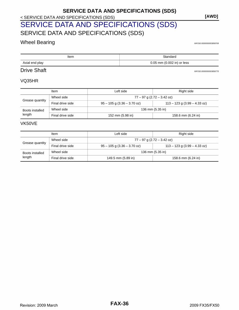
Wheel Bearing INFOID:0000000003858769
Drive Shaft INFOID:0000000003858770
VQ35HR
VK50VE
Item Standard
Axial end play 0.05 mm (0.002 in) or less
Item Left side Right side
Grease quantityWheel side 77 – 97 g (2.72 – 3.42 oz)
Final drive side 95 – 105 g (3.36 – 3.70 oz) 113 – 123 g (3.99 – 4.33 oz)
Boots installed length
Wheel side 136 mm (5.35 in)
Final drive side 152 mm (5.98 in) 158.6 mm (6.24 in)
Item Left side Right side
Grease quantityWheel side 77 – 97 g (2.72 – 3.42 oz)
Final drive side 95 – 105 g (3.36 – 3.70 oz) 113 – 123 g (3.99 – 4.33 oz)
Boots installed length
Wheel side 136 mm (5.35 in)
Final drive side 149.5 mm (5.89 in) 158.6 mm (6.24 in)
FAX-36Revision: 2009 March 2009 FX35/FX50