TRANSIENT OVERVOLTAGES ON THE ELECTRICITY SUPPLY · PDF fileTRANSIENT OVERVOLTAGES ON THE...
12
Technical Note No. 9 August 2006 This Technical Note presents an overview of the adverse effects on connected equipment of transient overvoltages that can occur on the electricity distribution network, and how to provide protection against them. Integral Energy, your local Distribution Network Service Provider or the Integral Energy Power Quality and Reliability Centre can give you additional advice if you have particular concerns with these issues. Summary Impulsive transients are generally the result of lightning and can cause damage to both network components (e.g. transformers) and connected equipment (e.g. personal computers and television sets). Oscillatory transients such as those resulting from network capacitor switching are of lower magnitude and generally only affect the operation of connected equipment. Low voltage equipment can be protected from impulsive transients by using the concept of Zones of Protection to apply surge protection devices and shielding techniques. Impulsive transients on electricity distribution networks can be controlled to some degree by the use of shielding conductors on overhead power lines and by using surge arresters. Oscillatory transients can be minimised by using a range of techniques. In particular, capacitor switching transients can be controlled by using pre-insertion resistors and inductors in the switching device, by using synchronous-closing switches, and by detuning power factor correction capacitors or replacing them with harmonic filters, as appropriate. Contents 1. Introduction 2. Effects on the network and connected equipment 3. Mitigation of transient overvoltages 4. References and additional reading 5. Integral Energy Power Quality and Reliability Centre TRANSIENT OVERVOLTAGES ON THE ELECTRICITY SUPPLY NETWORK – EFFECTS ON CONNECTED EQUIPTMENT AND THEIR MITIGATION Power Quality and Reliablity Centre
Transcript of TRANSIENT OVERVOLTAGES ON THE ELECTRICITY SUPPLY · PDF fileTRANSIENT OVERVOLTAGES ON THE...
Technical Note No. 9 August 2006
TRANSIENT OVERVOLTAGES ON THE ELECTRICITY SUPPLY NETWORK – EFFECTS ON
CONNECTED EQUIPMENT AND THEIR MITIGATION
This Technical Note presents an overview of the adverse effects on connected equipment of transient overvoltages that can occur on the electricity distribution network, and how to provide protection against them. Integral Energy, your local Distribution Network Service Provider or the Integral Energy Power Quality and Reliability Centre can give you additional advice if you have particular concerns with these issues.
Summary Impulsive transients are generally the result of lightning and can cause damage to both network components (e.g. transformers) and connected equipment (e.g. personal computers and television sets). Oscillatory transients such as those resulting from network capacitor switching are of lower magnitude and generally only affect the operation of connected equipment. Low voltage equipment can be protected from impulsive transients by using the concept of Zones of Protection to apply surge protection devices and shielding techniques. Impulsive transients on electricity distribution networks can be controlled to some degree by the use of shielding conductors on overhead power lines and by using surge arresters. Oscillatory transients can be minimised by using a range of techniques. In particular, capacitor switching transients can be controlled by using pre-insertion resistors and inductors in the switching device, by using synchronous-closing switches, and by detuning power factor correction capacitors or replacing them with harmonic filters, as appropriate. Contents
1. Introduction 2. Effects on the network and connected equipment 3. Mitigation of transient overvoltages 4. References and additional reading 5. Integral Energy Power Quality and Reliability Centre
TRANSIENT OVERVOLTAGES ONTHE ELECTRICITY SUPPLYNETWORK – EFFECTS ON
CONNECTED EQUIPTMENT ANDTHEIR MITIGATION
Powe
rQua
lity
and
Relia
blity
Cen
tre
1. Introduction The previous Technical Note No. 8 gave an overview of the transient overvoltages that can occur on the electricity distribution network, how they are classified, their causes, and how they propagate through the network. This Technical Note will indicate their impact on network and customer equipment, and suggest ways to either protect distribution networks and customer equipment or prevent the transient overvoltages from occurring.
2. Effects on the network and connected equipment
2.1 Impact on network
equipment
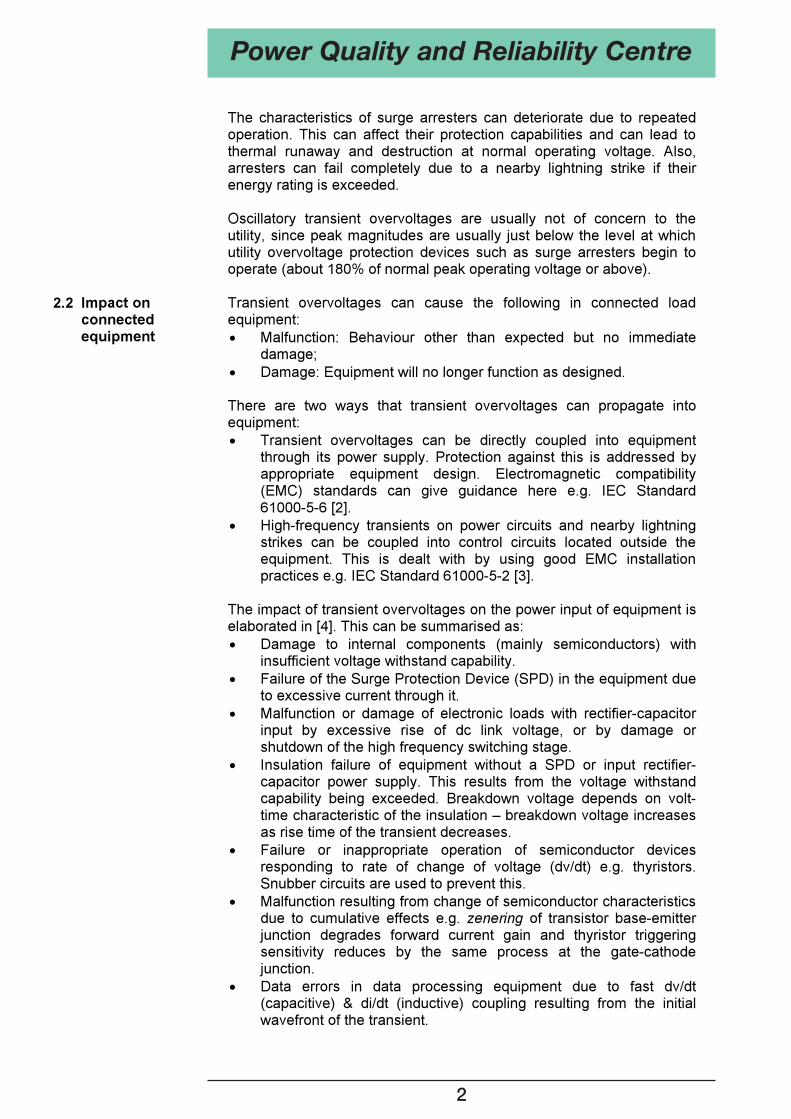
Lightning transients can cause damage to network equipment such as insulators, overhead-underground line connections and transformers if they are not adequately protected from transient overvoltages. Insulators at bends in the line are particularly vulnerable due to electric field distortion that can initiate flashover to earth. At overhead-underground cable terminations, cable aging can result in only a moderate transient overvoltage causing insulation breakdown and failure. Transformers, reactors and motors can fail due to high voltages appearing across the first few turns of their windings as a result of the capacitive effects. Due to the relative distribution of inter-turn capacitance and turn-ground capacitance, most of the transient voltage can initially appear across the first few turns of the winding leading to insulation failure. This is illustrated in Figure 1 for a transformer winding. The diagram on the left shows the initial high concentration of voltage across the section of the winding near the line terminal at the instant of incidence of the transient. About 65% of the applied voltage appears across the top 20% of the winding. The diagram on the right shows the subsequent distribution of voltage with time (in s) as it moves to its final uniform state indicating the oscillatory nature of the response of the winding to the applied transient overvoltage.
Figure 1: Transient voltage distribution across transformer winding [1].
Transients can also reduce insulation life without causing immediate insulation failure. Partial discharge activity can be initiated by the transient at local defects in the insulation leading to eventual insulation deterioration and failure.
Power Quality and Reliability Centre
1
The characteristics of surge arresters can deteriorate due to repeated operation. This can affect their protection capabilities and can lead to thermal runaway and destruction at normal operating voltage. Also, arresters can fail completely due to a nearby lightning strike if their energy rating is exceeded. Oscillatory transient overvoltages are usually not of concern to the utility, since peak magnitudes are usually just below the level at which utility overvoltage protection devices such as surge arresters begin to operate (about 180% of normal peak operating voltage or above).
2.2 Impact on connected equipment
Transient overvoltages can cause the following in connected load equipment:
Malfunction: Behaviour other than expected but no immediate damage; Damage: Equipment will no longer function as designed.
There are two ways that transient overvoltages can propagate into equipment:
Transient overvoltages can be directly coupled into equipment through its power supply. Protection against this is addressed by appropriate equipment design. Electromagnetic compatibility (EMC) standards can give guidance here e.g. IEC Standard 61000-5-6 [2]. High-frequency transients on power circuits and nearby lightning strikes can be coupled into control circuits located outside the equipment. This is dealt with by using good EMC installation practices e.g. IEC Standard 61000-5-2 [3].
The impact of transient overvoltages on the power input of equipment is elaborated in [4]. This can be summarised as:
Damage to internal components (mainly semiconductors) with insufficient voltage withstand capability. Failure of the Surge Protection Device (SPD) in the equipment due to excessive current through it. Malfunction or damage of electronic loads with rectifier-capacitor input by excessive rise of dc link voltage, or by damage or shutdown of the high frequency switching stage. Insulation failure of equipment without a SPD or input rectifier-capacitor power supply. This results from the voltage withstand capability being exceeded. Breakdown voltage depends on volt-time characteristic of the insulation – breakdown voltage increases as rise time of the transient decreases. Failure or inappropriate operation of semiconductor devices responding to rate of change of voltage (dv/dt) e.g. thyristors. Snubber circuits are used to prevent this. Malfunction resulting from change of semiconductor characteristics due to cumulative effects e.g. zenering of transistor base-emitter junction degrades forward current gain and thyristor triggering sensitivity reduces by the same process at the gate-cathode junction. Data errors in data processing equipment due to fast dv/dt (capacitive) & di/dt (inductive) coupling resulting from the initial wavefront of the transient.
Power Quality and Reliability Centre
2
As a result of direct or indirect lightning strikes, lightning currents may reach the end-user and generate very high impulsive transient overvoltages causing severe damage to equipment if not properly protected by appropriately rated surge protection devices. Also, lightning stroke currents entering the ground system may cause failure of equipment through earth potential rise and induce high voltages in phase conductors. Electronic equipment, both domestic (e.g. TVs and PCs), and industrial (e.g. programmable logic controllers (PLC) and variable speed drives (VSD)), are particularly susceptible to such transient effects. Oscillatory transient overvoltages usually have peak values below the operating thresholds of surge protection devices. However, they may still affect the operation of some equipment:
Sensitive electronic or power electronic equipment can malfunction or be damaged; Nuisance tripping of variable speed drives can occur due to dc bus overvoltages (as low as 120% of operating voltage); High line-line overvoltages may result on a transformer due to the magnification effects of power factor correction capacitors; Computer network problems can occur e.g. data corruption.
3. Mitigation of
transient overvoltages
Mitigation of transient effects can be applied: On the distribution network by the Distribution Network Service Provider (DNSP); At the equipment location by the customer; Within the equipment by the equipment manufacturer.
The most cost-effective solution usually lies with the equipment manufacturer so it is important that before purchase the customer correctly specifies the transient overvoltage capabilities of the equipment. Advice should be sought from your DNSP concerning the transient overvoltage performance of the distribution network in your area. The following discussion of transient overvoltage mitigation methods will consider both protection of Low Voltage (LV) equipment and Medium Voltage (MV) distribution network solutions.
3.1 Protection of LV equipment
The basic principles of transient overvoltage protection are: Limit the voltage across the sensitive insulation; Divert the surge current away from the equipment; Block the surge current from entering the equipment; Bond ground references together; Limit/prevent surge currents flowing between grounds.
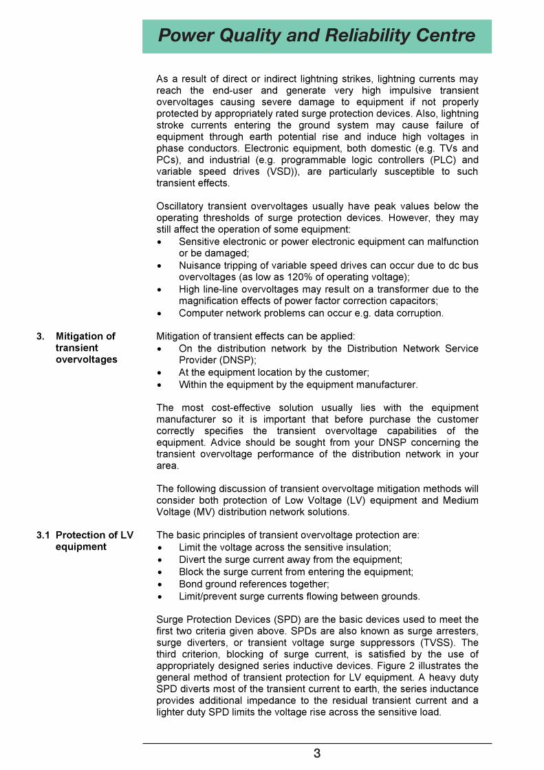
Surge Protection Devices (SPD) are the basic devices used to meet the first two criteria given above. SPDs are also known as surge arresters, surge diverters, or transient voltage surge suppressors (TVSS). The third criterion, blocking of surge current, is satisfied by the use of appropriately designed series inductive devices. Figure 2 illustrates the general method of transient protection for LV equipment. A heavy duty SPD diverts most of the transient current to earth, the series inductance provides additional impedance to the residual transient current and a lighter duty SPD limits the voltage rise across the sensitive load.
Power Quality and Reliability Centre
3
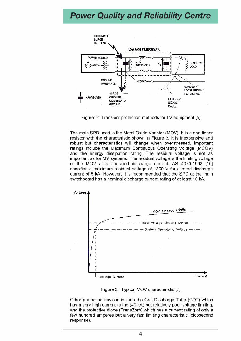
Figure: 2: Transient protection methods for LV equipment [5].
The main SPD used is the Metal Oxide Varistor (MOV). It is a non-linear resistor with the characteristic shown in Figure 3. It is inexpensive and robust but characteristics will change when overstressed. Important ratings include the Maximum Continuous Operating Voltage (MCOV) and the energy dissipation rating. The residual voltage is not as important as for MV systems. The residual voltage is the limiting voltage of the MOV at a specified discharge current. AS 4070-1992 [10] specifies a maximum residual voltage of 1300 V for a rated discharge current of 5 kA. However, it is recommended that the SPD at the main switchboard has a nominal discharge current rating of at least 10 kA.
Figure 3: Typical MOV characteristic [7]. Other protection devices include the Gas Discharge Tube (GDT) which has a very high current rating (40 kA) but relatively poor voltage limiting, and the protective diode (TransZorb) which has a current rating of only a few hundred amperes but a very fast limiting characteristic (picosecond response).
Power Quality and Reliability Centre
4
SPDs should be located as close as possible to critical insulation such as:
On the incoming supply at the main switchboard (at least Line-Neutral but Line-Earth and Neutral-Earth should also be considered where transients are a problem); On outgoing supplies to other buildings or on-site equipment; On power supplies within a building feeding sensitive equipment; On Uninterruptible Power Supply (UPS) systems – both input circuit and associated bypass circuits (automatic and manual).
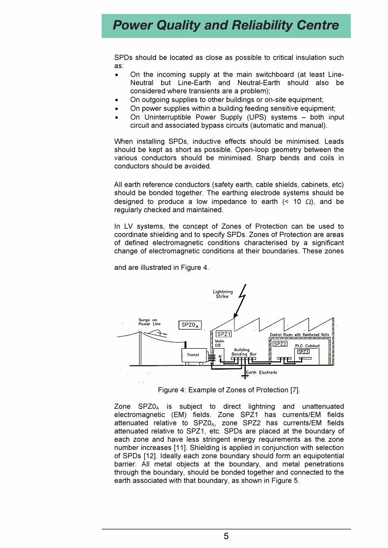
When installing SPDs, inductive effects should be minimised. Leads should be kept as short as possible. Open-loop geometry between the various conductors should be minimised. Sharp bends and coils in conductors should be avoided. All earth reference conductors (safety earth, cable shields, cabinets, etc) should be bonded together. The earthing electrode systems should be designed to produce a low impedance to earth (< 10 ), and be regularly checked and maintained. In LV systems, the concept of Zones of Protection can be used to coordinate shielding and to specify SPDs. Zones of Protection are areas of defined electromagnetic conditions characterised by a significant change of electromagnetic conditions at their boundaries. These zones are defined by the International Electrotechnical Commission (IEC) [6] and are illustrated in Figure 4.
Figure 4: Example of Zones of Protection [7].
Zone SPZ0A is subject to direct lightning and unattenuated electromagnetic (EM) fields. Zone SPZ1 has currents/EM fields attenuated relative to SPZ0A, zone SPZ2 has currents/EM fields attenuated relative to SPZ1, etc. SPDs are placed at the boundary of each zone and have less stringent energy requirements as the zone number increases [11]. Shielding is applied in conjunction with selection of SPDs [12]. Ideally each zone boundary should form an equipotential barrier. All metal objects at the boundary, and metal penetrations through the boundary, should be bonded together and connected to the earth associated with that boundary, as shown in Figure 5.
Power Quality and Reliability Centre
5
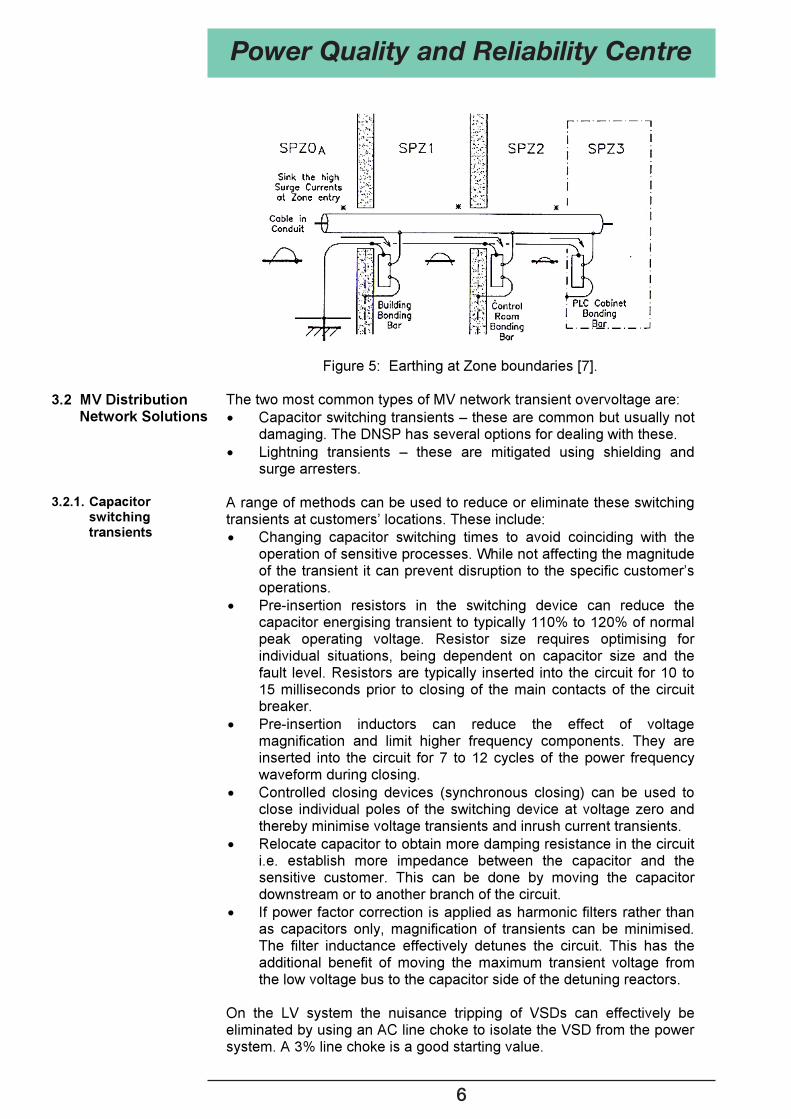
Figure 5: Earthing at Zone boundaries [7].
3.2 MV Distribution Network Solutions
The two most common types of MV network transient overvoltage are: Capacitor switching transients – these are common but usually not damaging. The DNSP has several options for dealing with these. Lightning transients – these are mitigated using shielding and surge arresters.
3.2.1. Capacitor
switching transients
A range of methods can be used to reduce or eliminate these switching transients at customers’ locations. These include:
Changing capacitor switching times to avoid coinciding with the operation of sensitive processes. While not affecting the magnitude of the transient it can prevent disruption to the specific customer’s operations. Pre-insertion resistors in the switching device can reduce the capacitor energising transient to typically 110% to 120% of normal peak operating voltage. Resistor size requires optimising for individual situations, being dependent on capacitor size and the fault level. Resistors are typically inserted into the circuit for 10 to 15 milliseconds prior to closing of the main contacts of the circuit breaker. Pre-insertion inductors can reduce the effect of voltage magnification and limit higher frequency components. They are inserted into the circuit for 7 to 12 cycles of the power frequency waveform during closing. Controlled closing devices (synchronous closing) can be used to close individual poles of the switching device at voltage zero and thereby minimise voltage transients and inrush current transients. Relocate capacitor to obtain more damping resistance in the circuit i.e. establish more impedance between the capacitor and the sensitive customer. This can be done by moving the capacitor downstream or to another branch of the circuit. If power factor correction is applied as harmonic filters rather than as capacitors only, magnification of transients can be minimised. The filter inductance effectively detunes the circuit. This has the additional benefit of moving the maximum transient voltage from the low voltage bus to the capacitor side of the detuning reactors.
On the LV system the nuisance tripping of VSDs can effectively be eliminated by using an AC line choke to isolate the VSD from the power system. A 3% line choke is a good starting value.
Power Quality and Reliability Centre
6
3.2.2 Lightning transients
The Lightning Protection System (LPS) for substations and overhead (OH) lines consists of:
Air terminals (vertical rods/masts, shield wires); A down-conductor system; An earth termination system; Properly selected and located surge arresters; Adequate insulation to withstand the remaining lightning overvoltages i.e. a Basic Insulation Level (BIL) 200 kV.
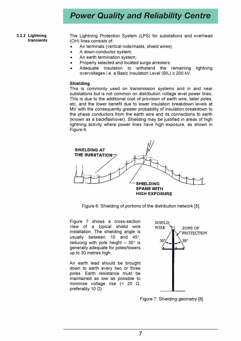
Shielding This is commonly used on transmission systems and in and near substations but is not common on distribution voltage level power lines. This is due to the additional cost of provision of earth wire, taller poles, etc, and the lower benefit due to lower insulation breakdown levels at MV with the consequently greater probability of insulation breakdown to the phase conductors from the earth wire and its connections to earth (known as a backflashover). Shielding may be justified in areas of high lightning activity where power lines have high exposure, as shown in Figure 6.
Figure 6: Shielding of portions of the distribution network [5].
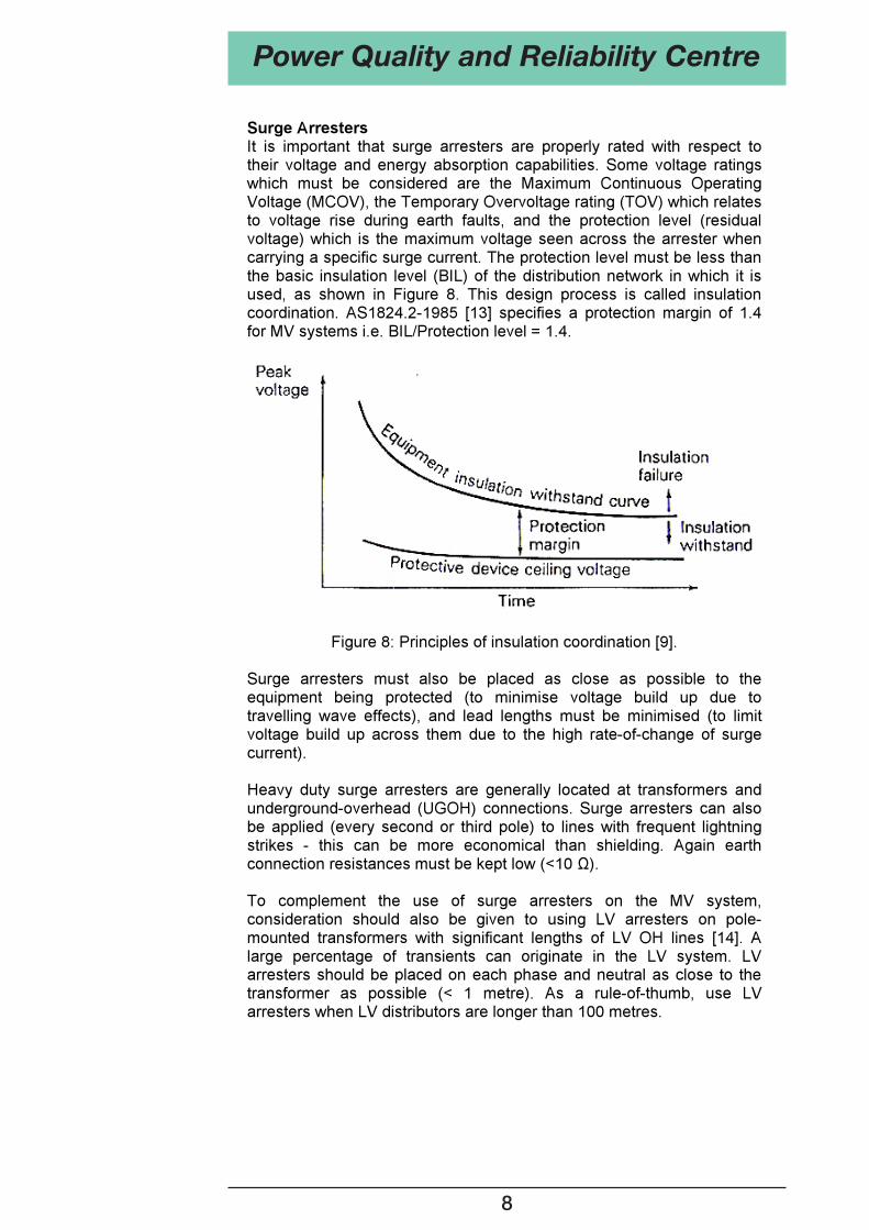
Figure 7 shows a cross-section view of a typical shield wire installation. The shielding angle is usually between 10 and 45 ,reducing with pole height – 30 is generally adequate for poles/towers up to 30 metres high.
An earth lead should be brought down to earth every two or three poles. Earth resistance must be maintained as low as possible to minimise voltage rise (< 20 ,preferably 10 ).
Figure 7: Shielding geometry [8].
Power Quality and Reliability Centre
7
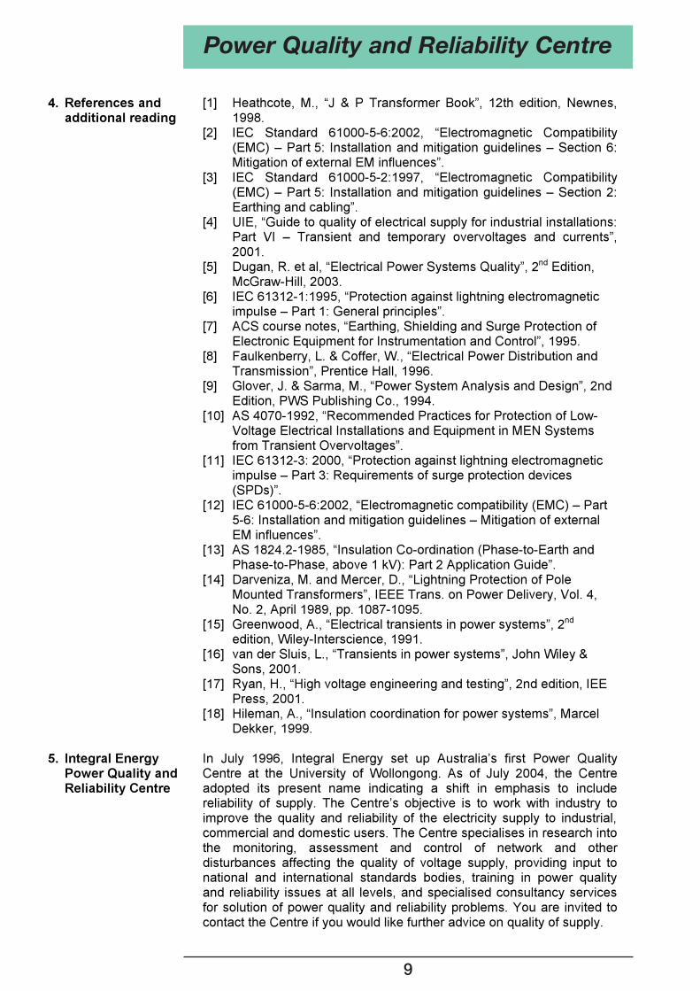
Surge Arresters It is important that surge arresters are properly rated with respect to their voltage and energy absorption capabilities. Some voltage ratings which must be considered are the Maximum Continuous Operating Voltage (MCOV), the Temporary Overvoltage rating (TOV) which relates to voltage rise during earth faults, and the protection level (residual voltage) which is the maximum voltage seen across the arrester when carrying a specific surge current. The protection level must be less than the basic insulation level (BIL) of the distribution network in which it is used, as shown in Figure 8. This design process is called insulation coordination. AS1824.2-1985 [13] specifies a protection margin of 1.4 for MV systems i.e. BIL/Protection level = 1.4.
Figure 8: Principles of insulation coordination [9]. Surge arresters must also be placed as close as possible to the equipment being protected (to minimise voltage build up due to travelling wave effects), and lead lengths must be minimised (to limit voltage build up across them due to the high rate-of-change of surge current). Heavy duty surge arresters are generally located at transformers and underground-overhead (UGOH) connections. Surge arresters can also be applied (every second or third pole) to lines with frequent lightning strikes - this can be more economical than shielding. Again earth connection resistances must be kept low (<10 ). To complement the use of surge arresters on the MV system, consideration should also be given to using LV arresters on pole-mounted transformers with significant lengths of LV OH lines [14]. A large percentage of transients can originate in the LV system. LV arresters should be placed on each phase and neutral as close to the transformer as possible (< 1 metre). As a rule-of-thumb, use LV arresters when LV distributors are longer than 100 metres.
Power Quality and Reliability Centre
8
4. References and additional reading
[1] Heathcote, M., “J & P Transformer Book”, 12th edition, Newnes, 1998.
[2] IEC Standard 61000-5-6:2002, “Electromagnetic Compatibility (EMC) – Part 5: Installation and mitigation guidelines – Section 6: Mitigation of external EM influences”.
[3] IEC Standard 61000-5-2:1997, “Electromagnetic Compatibility (EMC) – Part 5: Installation and mitigation guidelines – Section 2: Earthing and cabling”.
[4] UIE, “Guide to quality of electrical supply for industrial installations: Part VI – Transient and temporary overvoltages and currents”, 2001.
[5] Dugan, R. et al, “Electrical Power Systems Quality”, 2nd Edition, McGraw-Hill, 2003.
[6] IEC 61312-1:1995, “Protection against lightning electromagnetic impulse – Part 1: General principles”.
[7] ACS course notes, “Earthing, Shielding and Surge Protection of Electronic Equipment for Instrumentation and Control”, 1995.
[8] Faulkenberry, L. & Coffer, W., “Electrical Power Distribution and Transmission”, Prentice Hall, 1996.
[9] Glover, J. & Sarma, M., “Power System Analysis and Design”, 2nd Edition, PWS Publishing Co., 1994.
[10] AS 4070-1992, “Recommended Practices for Protection of Low-Voltage Electrical Installations and Equipment in MEN Systems from Transient Overvoltages”.
[11] IEC 61312-3: 2000, “Protection against lightning electromagnetic impulse – Part 3: Requirements of surge protection devices (SPDs)”.
[12] IEC 61000-5-6:2002, “Electromagnetic compatibility (EMC) – Part 5-6: Installation and mitigation guidelines – Mitigation of external EM influences”.
[13] AS 1824.2-1985, “Insulation Co-ordination (Phase-to-Earth and Phase-to-Phase, above 1 kV): Part 2 Application Guide”.
[14] Darveniza, M. and Mercer, D., “Lightning Protection of Pole Mounted Transformers”, IEEE Trans. on Power Delivery, Vol. 4, No. 2, April 1989, pp. 1087-1095.
[15] Greenwood, A., “Electrical transients in power systems”, 2nd edition, Wiley-Interscience, 1991.
[16] van der Sluis, L., “Transients in power systems”, John Wiley & Sons, 2001.
[17] Ryan, H., “High voltage engineering and testing”, 2nd edition, IEE Press, 2001.
[18] Hileman, A., “Insulation coordination for power systems”, Marcel Dekker, 1999.
5. Integral Energy
Power Quality and Reliability Centre
In July 1996, Integral Energy set up Australia’s first Power Quality Centre at the University of Wollongong. As of July 2004, the Centre adopted its present name indicating a shift in emphasis to include reliability of supply. The Centre’s objective is to work with industry to improve the quality and reliability of the electricity supply to industrial, commercial and domestic users. The Centre specialises in research into the monitoring, assessment and control of network and other disturbances affecting the quality of voltage supply, providing input to national and international standards bodies, training in power quality and reliability issues at all levels, and specialised consultancy services for solution of power quality and reliability problems. You are invited to contact the Centre if you would like further advice on quality of supply.
Power Quality and Reliability Centre
9

10
ABOUT THE AUTHORS Vic Smith is the Research Engineer with the Integral Energy Power Quality and Reliability Centre. Venthanar Ilango (recently deceased) was a Professional Officer in the School of Electrical, Computer and Telecommunications Engineering at the University of Wollongong. Sarath Perera is the Technical Director of the Integral Energy Power Quality and Reliability Centre and an Associate Professor in the School of Electrical, Computer and Telecommunications Engineering at the University of Wollongong. Vic Gosbell is an Honorary Professorial Fellow in the School of Electrical, Computer and Telecommunications Engineering at the University of Wollongong and is Technical Advisor to the Integral Energy Power Quality and Reliability Centre. .
Power Quality and Reliability Centre
11
Power Quality and Reliability Centre
FURTHER INFORMATION CAN BE OBTAINED BY CONTACTING: Dr. S. Perera
Technical Director
Integral Energy Power Quality and Reliability Centre
School of Electrical, Computer and Telecommunications Engineering
University of Wollongong
NSW AUSTRALIA 2522
Ph: (02) 4221 4500 or (02) 4221 3405 Fax: (02) 4221 3236
Email: [email protected]