
Transformers - Главная страница сайта ООО...
36
Contents Page Introduction ....................................... 5/2 Product Range .................................. 5/3 Electrical Design .............................. 5/4 Transformer Loss Evaluation ......... 5/6 Mechanical Design ......................... 5/8 Connection Systems ....................... 5/9 Accessories and Protective Devices ........................ 5/11 Technical Data Distribution Transformers ............ 5/13 Technical Data Power Transformers ...................... 5/18 On-load Tap Changers .................. 5/26 Cast-resin Dry-type Transformers, GEAFOL .................. 5/27 Technical Data GEAFOL Cast-resin Dry-type Transformers .................. 5/31 Special Transformers .................... 5/35 Transformers Transformers 5
Transcript of Transformers - Главная страница сайта ООО...

Contents PageIntroduction ....................................... 5/2
Product Range .................................. 5/3
Electrical Design .............................. 5/4
Transformer Loss Evaluation ......... 5/6
Mechanical Design ......................... 5/8
Connection Systems ....................... 5/9
Accessories andProtective Devices ........................ 5/11
Technical DataDistribution Transformers ............ 5/13
Technical DataPower Transformers ...................... 5/18
On-load Tap Changers .................. 5/26
Cast-resin Dry-typeTransformers, GEAFOL .................. 5/27
Technical DataGEAFOL Cast-resinDry-type Transformers .................. 5/31
Special Transformers .................... 5/35
TransformersTransformers
5Ohne Namen-1 22.09.1999, 16:22 Uhr1

1
2
3
4
5
6
7
8
9
10
5/2 Siemens Power Engineering Guide · Transmission and Distribution · 4th Edition
Introduction
In addition, there are various special-purpose transformers such as convertertransformers, which can be both in therange of power transformers and in therange of distribution transformers as faras rated power and rated voltage are con-cerned.As special elements for network stabili-zation, arc-suppression coils and com-pensating reactors are available. Arc-sup-pression coils compensate the capacitivecurrent flowing through a ground fault andthus guarantee uninterrupted energy sup-ply. Compensating reactors compensatethe capacitive power of the cable networksand reduce overvoltages in case of loadrejection; the economic efficiency andstablility of the power transmission are im-proved.The general overview of our manufactur-ing/delivery program is shown in thetable ”Product Range“.
Standards and specifications, general
The transformers comply with the relevantVDE specifications, i.e. DIN VDE 0532”Transformers and reactors“ and the”Technical conditions of supply for three-phase transformers“ issued by VDEWand ZVEI.Therefore they also satisfy the require-ments of IEC Publication 76, Parts 1 to 5together with the standards and specifi-cations (HD and EN) of the EuropeanUnion (EU).Enquiries should be directed to the manu-facturer where other standards and spe-cifications are concerned. Only the US(ANSI/NEMA) and Canadian (CSA) stand-ards differ from IEC by any substantial de-gree. A design according to these stand-ards is also possible.
Important additional standards
■ DIN 42 500, HD 428: oil-immersedthree-phase distribution transformers50–2500 kVA
■ DIN 42 504: oil-immersed three-phasetransformers 2–10 MVA
■ DIN 42 508: oil-immersed three-phasetransformers 12.5–80 MVA
■ DIN 42 523, HD 538: three-phasedry-type transformers 100–2500 kVA
■ DIN 45 635 T30: noise level■ IEC 289: reactance coils and neutral
grounding transformers■ IEC 551: measurement of noise level■ IEC 726: dry-type transformers■ RAL: coating/varnish
Transformers are one of the primarycomponents for the transmission anddistribution of electrical energy.Their design results mainly from the rangeof application, the construction, the ratedpower and the voltage level.The scope of transformer types starts withgenerator transformers and ends with dis-tribution transformers.Transformers which are directly connectedto the generator of the power station arecalled generator transformers. Their powerrange goes up to far above 1000 MVA.Their voltage range extends to approx.1500 kV.The connection between the different high-voltage system levels is made via networktransformers (network interconnectingtransformers). Their power range exceeds1000 MVA. The voltage range exceeds1500 kV.Distribution transformers are within therange from 50 to 2500 kVA and max.36 kV. In the last step, they distributethe electrical energy to the consumersby feeding from the high-voltage into thelow-voltage distribution network. Theseare designed either as liquid-filled or asdry-type transformers.Transformers with a rated power up to2.5 MVA and a voltage up to 36 kV arereferred to as distribution transformers;all transformers of higher ratings areclassified as power transformers.
0.05–2.5
2.5–3000
0.10–20
≤ 36
36–1500
≤ 36
Ratedpower
Max.operatingvoltage
[MVA] [kV]
Oildistributiontransformers
GEAFOL-cast-resintransformers
Powertransformers
5/13–5/17
5/18–5/25
5/27–5/34
Figs.onpage
Fig. 1: Transformer types
Ohne Namen-1 22.09.1999, 16:23 Uhr2

1
2
3
4
5
6
7
8
9
10
Siemens Power Engineering Guide · Transmission and Distribution · 4th Edition 5/3
Product Range
Above 2.5 MVA up to more than 1000 MVA, above 30 kV up to 1500 kV(system and system interconnecting transformers, with separate windings orauto-connected), with on-load tap changers or off-circuit tap changers,of three- or single-phase design
Generator and powertransformers
50 to 2 500 kVA, highest voltage for equipment up to 36 kV,with copper or aluminum windings, hermetically sealed (TUMETIC®) orwith conservator (TUNORMA®) of three- or single-phase design
Oil-immerseddistribution transformers,TUMETIC, TUNORMA
Buchholz relays, oil testing equipment,oil flow indicators and other monitoring devicesFan control cabinets, control cabinets for parallel operation andautomatic voltage controlSensors (PTC, Pt 100)
Accessories
Advisory services for transformer specificationsOrganization, coordination and supervision of transportationSupervision of assembly and commissioningService/inspection troubleshooting servicesTraining of customer personnelInvestigation and assessment of oil problems
Service
Furnace and converter transformersTraction transformers mounted on rolling stock and appropriate on-load tap-changersSubstation transformers for traction systemsTransformers for train heating and point heatingTransformers for HVDC transmission systemsTransformers for audio frequencies in power supply systemsThree-phase neutral electromagnetic couplers and grounding transformersIgnition transformers
Special transformersfor industry, tractionand HVDC transmissionsystems
100 kVA to more than 20 MVA, highest voltage for equipment up to 36 kV,of three- or single-phase designGEAFOL®-SL substations
Cast-resin distributionand power transformersGEAFOL
Liquid-immersed shunt and current-limiting reactors up tothe highest rated powersReactors for HVDC transmission systems
Reactors
Fig. 2
Ohne Namen-1 22.09.1999, 16:23 Uhr3

1
2
3
4
5
6
7
8
9
10
5/4 Siemens Power Engineering Guide · Transmission and Distribution · 4th Edition
Dy1
iii
Dy5
Dy11
Yd1
Yd5
Yd11
ii
i
III II
I1
iiiii
iIII II
I
5
iiiii
i
III II
I11
iii
iii
III II
I11
iiiii
iIII II
I
5
iii
ii
i
III II
I1
Electrical Design
Power ratings and type of cooling
All power ratings in this guide are the pro-duct of rated voltage (times phase-factorfor three-phase transformers) and ratedcurrent of the line side winding (at centertap, if several taps are provided), expres-sed in kVA or MVA, as defined in IEC 76-1.If only one power rating and no coolingmethod are shown, natural oil-air cooling(ONAN or OA) is implied for oil-immersedtransformers. If two ratings are shown,forced-air cooling (ONAF or FA) in one ortwo steps is applicable.For cast resin transformers, natural aircooling (AN) is standard. Forced air cooling(AF) is also applicable.
Temperature rise
In accordance with IEC-76 the standardtemperature rise for oil-immersed powerand distribution transformers is:■ 65 K average winding temperature
(measured by the resistance method)■ 60 K top oil temperature
(measured by thermometer)The standard temperature rise for Siemenscast-resin transformers is■ 100 K (insulation class F) at HV and
LV winding.Whereby the standard ambient tempera-tures are defined as follows:■ 40 °C maximum temperature,■ 30 °C average on any one day,■ 20 °C average in any one year,■ –25 °C lowest temperature outdoors,■ –5 °C lowest temperature indoors.Higher ambient temperatures require acorresponding reduction in temperaturerise, and thus affect price or rated poweras follows:■ 1.5% surcharge for each 1 K above
standard temperature conditions, or■ 1.0% reduction of rated power for each
1 K above standard temperature condi-tions.
These adjustment factors are applicableup to 15 K above standard temperatureconditions.
Altitude of installation
The transformers are suitable for operationat altitudes up to 1000 meters above sealevel. Site altitudes above 1000 m necessi-tate the use of special designs and an in-crease/or a reduction of the transformerratings as follows (approximate values):
The primary winding (HV) is normallyconnected in delta, the secondary winding(LV) in wye. The electrical offset of thewindings in respect to each other is either30, 150 or 330 degrees standard (Dy1,Dy5, Dy11). Other vector groups aswell as single-phase transformers andautotransformers on request (Fig. 3).
Power transformers
Generator transformers and large powertransformers are usually connected in Yd.For HV windings higher than 110 kV, theneutral has a reduced insulation level.For star/star-connected transformers andautotransformers normally a tertiary wind-ing in delta, whose rating is a third of thatof the transformer, has to be added. Thisstabilizes the phase-to phase voltages inthe case of an unbalanced load and pre-vents the displacement of the neutralpoint.Single-phase transformers and autotrans-formers are used when the transportationpossibilities are limited. They will be con-nected at site to three-phase transformerbanks.
■ 2% increase for every 500 m altitude (orpart there of) in excess of 1000 m, or
■ 2% reduction of rated power for each500 m altitude (or part there of) in ex-cess of 1000 m.
Transformer losses and efficiencies
Losses and efficiencies stated in this guideare average values for guidance only. Theyare applicable if no loss evaluation figure isstated in the inquiry (see following chapter)and they are subject to the tolerances stat-ed in IEC 76-1, namely +10% of the totallosses, or +15% of each component loss,provided that the tolerance for the totallosses is not exceeded.If optimized and/or guaranteed losses with-out tolerances are required, this must bestated in the inquiry.
Connections and vector groups
Distribution transformers
The transformers listed in this guide areall three-phase transformers with one setof windings connected in star (wye) andthe other one in delta, whereby the neutralof the star-connected winding is fully ratedand brought to the outside.
Fig. 3: Most commonly used vector groups
Ohne Namen-1 22.09.1999, 16:23 Uhr4
1
2
3
4
5
6
7
8
9
10
Siemens Power Engineering Guide · Transmission and Distribution · 4th Edition 5/5
Electrical Design
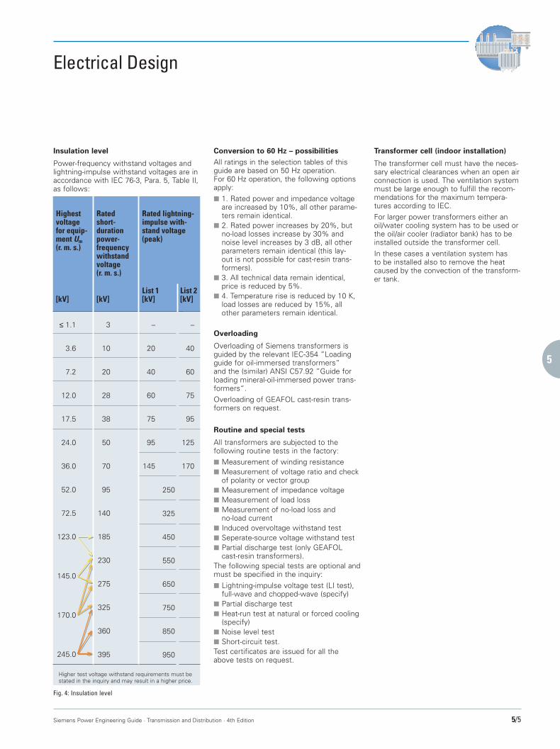
≤ 1.1
3.6
7.2
12.0
17.5
24.0
36.0
52.0
72.5
123.0
145.0
170.0
245.0
Highestvoltagefor equip-ment Um(r. m. s.)
[kV]
Ratedshort-durationpower-frequencywithstandvoltage(r. m. s.)
[kV]
Rated lightning-impulse with-stand voltage(peak)
List 1[kV]
List 2[kV]
3
10
20
28
38
50
70
95
140
185
230
275
325
360
395
–
20
40
60
75
95
145
–
40
60
75
95
125
170
250
325
450
550
650
750
850
950
Higher test voltage withstand requirements must bestated in the inquiry and may result in a higher price.
Fig. 4: Insulation level
Insulation level
Power-frequency withstand voltages andlightning-impulse withstand voltages are inaccordance with IEC 76-3, Para. 5, Table II,as follows:
Conversion to 60 Hz – possibilities
All ratings in the selection tables of thisguide are based on 50 Hz operation.For 60 Hz operation, the following optionsapply:■ 1. Rated power and impedance voltage
are increased by 10%, all other parame-ters remain identical.
■ 2. Rated power increases by 20%, butno-load losses increase by 30% andnoise level increases by 3 dB, all otherparameters remain identical (this lay-out is not possible for cast-resin trans-formers).
■ 3. All technical data remain identical,price is reduced by 5%.
■ 4. Temperature rise is reduced by 10 K,load losses are reduced by 15%, allother parameters remain identical.
Overloading
Overloading of Siemens transformers isguided by the relevant IEC-354 ”Loadingguide for oil-immersed transformers“and the (similar) ANSI C57.92 ”Guide forloading mineral-oil-immersed power trans-formers“.Overloading of GEAFOL cast-resin trans-formers on request.
Routine and special tests
All transformers are subjected to thefollowing routine tests in the factory:■ Measurement of winding resistance■ Measurement of voltage ratio and check
of polarity or vector group■ Measurement of impedance voltage■ Measurement of load loss■ Measurement of no-load loss and
no-load current■ Induced overvoltage withstand test■ Seperate-source voltage withstand test■ Partial discharge test (only GEAFOL
cast-resin transformers).The following special tests are optional andmust be specified in the inquiry:■ Lightning-impulse voltage test (LI test),
full-wave and chopped-wave (specify)■ Partial discharge test■ Heat-run test at natural or forced cooling
(specify)■ Noise level test■ Short-circuit test.Test certificates are issued for all theabove tests on request.
Transformer cell (indoor installation)
The transformer cell must have the neces-sary electrical clearances when an open airconnection is used. The ventilation systemmust be large enough to fulfill the recom-mendations for the maximum tempera-tures according to IEC.For larger power transformers either anoil/water cooling system has to be used orthe oil/air cooler (radiator bank) has to beinstalled outside the transformer cell.In these cases a ventilation system hasto be installed also to remove the heatcaused by the convection of the transform-er tank.
Ohne Namen-1 22.09.1999, 16:23 Uhr5

1
2
3
4
5
6
7
8
9
10
5/6 Siemens Power Engineering Guide · Transmission and Distribution · 4th Edition
q = p100
+ 1
A. Capital cost
B. Cost of no-load loss
C. Cost of load loss
D. Cost resulting from demands charges
Cc =Cp · r
100
= purchase price
= depreciation factor
= interest factor
= interest rate in % p.a.= depreciation period in years
Cp
r = p · qn
qn – 1
pn
CP0 = Ce · 8760 h/year · P0
= energy charges
= no-load loss [kW]
Ce
P0
amountkWh
CPk = Ce · 8760 h/year · α2 · Pk
amountyear
amountyear
amountyear
α
Pk
=
= copper loss [kW]
constant operation loadrated load
CD =amount
yearCd (P0 + Pk)
Cd = demand charges amountkW · year
Transformer Loss Evaluation
The sharply increased cost of electricalenergy has made it almost mandatory forbuyers of electrical machinery to carefullyevaluate the inherent losses of theseitems. In case of distribution and powertransformers, which operate continuouslyand most frequently in loaded condition,this is especially important. As an example,the added cost of loss-optimized trans-formers can in most cases be recoveredvia savings in energy use in less than threeyears.Low-loss transformers use more andbetter materials for their construction andthus initially cost more. By stipulating lossevaluation figures in the transformer in-quiry, the manufacturer receives the nec-essary incentive to provide a loss-opti-mized transformer rather than the low-cost model.Detailed loss evaluation methods fortransformers have been developed andare described accurately in the literature,taking the project-specific evaluation fac-tors of a given customer into account.The following simplified method for a quickevaluation of different quoted transformerlosses is given, making the following as-sumptions:■ The transformers are operated con-
tinuously■ The transformers operate at partial load,
but this partial load is constant■ Additional cost and inflation factors are
not considered■ Demand charges are based on 100%
load.The total cost of owning and operating atransformer for one year is thus defined asfollows:■ A. Capital cost Cc
taking into account the purchase priceCp, the interest rate p, and the depre-ciation period n
■ B. Cost of no-load loss CP0,based on the no-load loss P0, andenergy cost Ce
■ C. Cost of load loss Cpk,based on the copper loss Pk, the equi-valent annual load factor a, and energycost Ce
■ D. Demand charges Cd,based on the amount set by the utility,and the total kW of connected load.
These individual costs are calculated asfollows:
Fig. 5
Ohne Namen-1 22.09.1999, 16:23 Uhr6
1
2
3
4
5
6
7
8
9
10
Siemens Power Engineering Guide · Transmission and Distribution · 4th Edition 5/7
Transformer Loss Evaluation
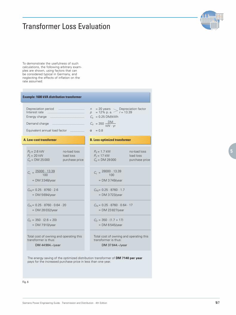
To demonstrate the usefulness of suchcalculations, the following arbitrary exam-ples are shown, using factors that canbe considered typical in Germany, andneglecting the effects of inflation on therate assumed:
A. Low-cost transformer B. Loss-optimized transformer
Depreciation periodInterest rateEnergy charge
Demand charge
Equivalent annual load factor
npCe
Cd
α
= 20 years= 12% p. a.= 0.25 DM/kWh
= 350
= 0.8
DMkW · yr
P0 = 2.6 kWPk = 20 kWCp = DM 25 000
P0 = 1.7 kWPk = 17 kWCp = DM 28 000
no-load lossload losspurchase price
no-load lossload losspurchase price
Cc25000 · 13.39
100
DM 3348/year
CP0 0.25 · 8760 · 2.6
DM 5694/year=
=
=
=
CPk 0.25 · 8760 · 0.64 · 20
DM 28 032/year=
=
CD 350 · (2.6 + 20)
DM 7910/year=
=
Total cost of owning and operating thistransformer is thus:
DM 44984.–/year
Cc28000 · 13.39
100
DM 3 749/year
CP0 0.25 · 8760 · 1.7
DM 3 723/year=
=
=
=
CPk 0.25 · 8760 · 0.64 · 17
DM 23 827/year=
=
CD 350 · (1.7 + 17)
DM 6 545/year=
=
Total cost of owning and operating thistransformer is thus:
DM 37 844.–/year
The energy saving of the optimized distribution transformer of DM 7140 per yearpays for the increased purchase price in less than one year.
Example: 1600 kVA distribution transformer
Depreciation factorr = 13.39
Fig. 6
Ohne Namen-1 22.09.1999, 16:23 Uhr7

1
2
3
4
5
6
7
8
9
10
5/8 Siemens Power Engineering Guide · Transmission and Distribution · 4th Edition
Mechanical Design
Fig. 9: Practically maintenancefree: transformer withthe TUPROTECT air-sealing system built into the con-servator
General mechanical designfor oil-immersed transformers:
■ Iron core made of grain-orientedelectrical sheet steel insulated on bothsides, core-type.
■ Windings consisting of copper sectionwire or copper strip. The insulationhas a high disruptive strength and istemperature-resistant, thus guaranteeinga long service life.
■ Designed to withstand short circuit forat least 2 seconds (IEC).
■ Oil-filled tank designed as tank withstrong corrugated walls or as radiatortank.
■ Transformer base with plain or flangedwheels (skid base available).
■ Cooling/insulation liquid: Mineral oilaccording to VDE 0370/IEC 296. Siliconeoil or synthetic liquids are available.
■ Standard coating for indoor installation.Coatings for outdoor installation andfor special applications (e.g. aggressiveatmosphere) are available.
Tank design andoil preservation system
Sealed-tank distribution transformers,TUMETIC®
In ratings up to 2500 kVA and 170 kV LIthis is the standard sealed-tank distributiontransformer without conservator and gascushion. The TUMETIC transformer isalways completely filled with oil; oil expan-sion is taken up by the flexible corrugatedsteel tank (variable volume tank design),whereby the maximum operating pressureremains at only a fraction of the usual.These transformers are always shippedcompletely filled with oil and sealed fortheir lifetime. Bushings can be exchangedfrom the outside without draining the oilbelow the top of the active part.The hermetically sealed system preventsoxygen, nitrogen, or humidity from contactwith the insulating oil. This improves theaging properties of the oil to the extentthat no maintenance is required on thesetransformers for their lifetime. Generallythe TUMETIC transformer is lower thanthe TUNORMA transformer. This designhas been in successful service since 1973.A special TUMETIC-Protection device hasbeen developed for this transformer.
Distribution transformers withconservator, TUNORMA®
This is the standard distribution transform-er design in all ratings. The oil level in thetank and the top-mounted bushings is keptconstant by a conservator vessel or expan-sion tank mounted at the highest point ofthe transformer. Oil-level changes due tothermal cycling affect the conservator only.The ambient air is prevented from directcontact with the insulating oil through oil-traps and dehydrating breathers.Tanks from 50 to approximately 4000 kVAare preferably of the corrugated steel de-sign, whereby the sidewalls are formed onautomatic machines into integral coolingpockets. Suitable spot welds and bracesrender the required mechanical stability.Tank bottom and cover are fabricated fromrolled and welded steel plate.Conventional radiators are available.
Power transformers
Power transformers of all ratings areequipped with conservators. Both the openand closed system are available.With the closed system ”TUPROTECT®“the oil does not come into contact with thesurrounding air. The oil expansion is com-pensated with an air bag. (This design isalso available for greater distribution trans-formers on request).The sealing bag consists of strong nylonbraid with a special double lining of ozoneand oil-resistant nitrile rubber. The interiorof this bag is in contact with the ambientair through a dehydrating breather;the outside of this bag is in direct contactwith the oil.All tanks, radiators and conservators(incl. conservator with airbag) are designedfor vacuum filling of the oil.For transformers with on-load tap changersa seperate smaller conservator is neces-sary for the diverter switch compartment.This seperate conservator (without air bag)is normally an integrated part of the mainconservator with its own magnetic oil levelindicator.Power transformers up to 10 MVA arefitted with weld-on radiators and areshipped extensively assembled; shippingconditions permitting.Ratings above 10 MVA require detachableradiators with individual butterfly valves,and partial dismantling of components forshipment.All the usual fittings and accessories for oiltreatment, shipping and installation ofthese transformers are provided as stand-ard. For monitoring and protective devices,see the listing on page 5/11.
Fig. 8: 630 kVA, three-phase, TUNORMA20 kV ± 2.5 %/0.4 kV distribution transformer
Fig. 7: Cross section of a TUMETIC three-phasedistribution transformer
Ohne Namen-1 22.09.1999, 16:23 Uhr8

1
2
3
4
5
6
7
8
9
10
Siemens Power Engineering Guide · Transmission and Distribution · 4th Edition 5/9
Connection Systems
Distribution transformers
All Siemens transformers have top-mount-ed HV and LV bushings according to DIN intheir standard version. Besides the openbushing arrangement for direct connectionof bare or insulated wires, three basic insu-lated termination systems are available:
Fully enclosed terminal box for cables(Fig. 11)
Available for either HV or LV side, or forboth. Horizontally split design in degreeof protection IP 44 or IP 54. (Totally en-closed and fully protected against contactwith live parts, plus protection against drip,splash, or spray water.)Cable installation through split cable glandsand removable plates facing diagonallydownwards. Optional conduit hubs. Suit-able for single-core or three-phase cableswith solid dielectric insulation, with orwithout stress cones. Multiple cables perphase are terminated on auxiliary busstructures attached to the bushings. Re-moval of transformer by simply bendingback the cables.
Insulated plug connectors (Fig. 12)
For substation installations, suitableHV can be attached via insulatedelbow connectors in LI ratings up to170 kV.
Flange connection (Fig. 13)
Air-insulated bus ducts, insulated busbars,or throat-connected switchgear cubiclesare connected via standardized flanges onsteel terminal enclosures. These can ac-commodate either HV, LV, or both bush-ings. Fiberglass-reinforced epoxy partitionsare available between HV and LV bushingsif flange/flange arrangements are chosen.The following combinations of connectionsystems are possible besides open bush-ing arrangements:
Cable box
Cable box
Flange
Flange
Elbow connector
Elbow connector
HV
Cable box
Flange/throat
Cable box
Flange/throat
Cable box
Flange/throat
LV
Fig 13: Flange connection for switchgear and bus ductsFig. 10: Combination of connection systems
Fig. 11: Fully enclosed cable connection box
Fig. 12: Grounded metal-elbow plug connectors
Ohne Namen-1 22.09.1999, 16:23 Uhr9

1
2
3
4
5
6
7
8
9
10
5/10 Siemens Power Engineering Guide · Transmission and Distribution · 4th Edition
Connection Systems
Power transformers
The most frequently used type of connec-tion for transformers is the outdoor bush-ing.Depending on voltage, current, systemconditions and transport requirements, thetransformers will be supplied with bush-ings arranged vertically, horizontally or in-clined. Up to about 110 kV it is usual touse oil-filled bushings according to DIN;condenser bushings are normally used forhigher voltages.Limited space or other design considera-tions often make it necessary to connectcables directly to the transformer. For volt-ages up to 30 kV air-filled cable boxes areused. For higher voltages the boxes areoil-filled. They may be attached to the tankcover or to its walls (Fig. 14).The space-saving design of SF6-insulatedswitchgear is one of its major advantages.The substation transformer is connecteddirectly to the SF6 switchgear. This elimi-nates the need for an intermediate link(cable, overhead line) between transform-er and system (Fig. 15).
Fig. 14: Transformers with oil-filled HV cable boxes
Fig. 15: Direct SF6-connection of the transformer to the switchgear
Ohne Namen-1 22.09.1999, 16:23 Uhr10

1
2
3
4
5
6
7
8
9
10
Siemens Power Engineering Guide · Transmission and Distribution · 4th Edition 5/11
Accessories and Protective DevicesAccessories not listed completely.Deviations are possible.
Fig. 16: Double-float Buchholz relay
Fig. 17: Dial-type contact thermometer
Double-float Buchholz relay (Fig. 16)
For sudden pressure rise and gas detec-tion in oil-immersed transformer tanks withconservator. Installed in the connectingpipe between tank and conservator andresponding to internal arcing faults andslow decomposition of insulating materials.Additionally, backup function of oil alarm.The relay is actuated either by pressurewaves or gas accumulation, or by loss ofoil below the relay level. Seperate contactsare installed for alarm and tripping.In case of a gas accumulation alarm, gassamples can be drawn directly at the relaywith a small chemical testing kit. Discolor-ing of two liquids indicates either arcing by-products or insulation decomposition prod-ucts in the oil. No change in color indicatesan air bubble.
Dial-type contact thermometer (Fig. 17)
Indicates actual top-oil temperature viacapillary tube. Sensor mounted in well intank cover. Up to four separately adjust-able alarm contacts and one maximumpointer are available. Installed to be read-able from the ground.With the addition of a CT-fed thermal re-plica circuit, the simulated hot-spot wind-ing temperature of one or more phasescan be indicated on identical thermo-meters. These instruments can also beused to control forced cooling equipment.
Magnetic oil-level indicator (Fig. 18)
The float position inside of the conservatoris transmitted magnetically through thetank wall to the indicator to preserve thetank sealing standard device without con-tacts; devices supplied with limit (position)switches for high- and low-level alarm areavailable. Readable from the ground.
Fig. 18: Magnetic oil-level indicator
Ohne Namen-1 22.09.1999, 16:23 Uhr11

1
2
3
4
5
6
7
8
9
10
5/12 Siemens Power Engineering Guide · Transmission and Distribution · 4th Edition
Accessories and Protective Devices
Protective device (Fig. 19) for hermeti-cally sealed transformers (TUMETIC)
For use on hermetically sealed TUMETICdistribution transformers. Gives alarmupon loss of oil and gas accumulation.Mounted directly at the (permanentlysealed) filler pipe of these transformers.
Pressure relief device (Fig. 20)
Relieves abnormally high internal pressureshock waves. Easily visible operationpointer and alarm contact. Reseals posi-tively after operation and continues tofunction without operator action.
Dehydrating breather (Fig. 21, 22)
A dehydrating breather removes most ofthe moisture from the air which is drawninto the conservator as the transformercools down. The absence of moisture inthe air largely eliminates any reduction inthe breakdown strength of the insulationand prevents any buildup of condensationin the conservator. Therefore, the dehy-drating breather contributes to safe andreliable operation of the transformer.
Bushing current transformer
Up to three ring-type current transformersper phase can be installed in power trans-formers on the upper and lower voltageside. These multiratio CTs are supplied inall common accuracy and burden ratingsfor metering and protection. Their second-ary terminals are brought out to short-circuiting-type terminal blocks in watertightterminal boxes.
Additional accessories
Besides the standard accessories and pro-tective devices there are additional itemsavailable, especially for large power trans-formers. They will be offered and installedon request.Examples are:■ Fiber-optic temperature measurements■ Permanent gas-in-oil analysis■ Permanent water-content measurement■ Sudden pressure rise relay,etc.
Fig. 20: Pressure relief device with alarm contact andautomatic resetting
Fig. 19: Protective device for hermetically sealedtransformers (TUMETIC)
Fig. 21: Dehydrating breather A DIN 42 567up to 5 MVA
Fig. 22: Dehydrating breather L DIN 42 562over 5 MVA
Ohne Namen-1 22.09.1999, 16:23 Uhr12

1
2
3
4
5
6
7
8
9
10
Siemens Power Engineering Guide · Transmission and Distribution · 4th Edition 5/13
8
2W2V2U2N
1W2U1U
Oil drain plugThermometer pocketAdjustment for off-load tap changerRating plate (relocatable)Grounding terminals
23678
Towing eye, 30 mm dia.Lashing lugFiller pipeMounting facility forprotective device
9101112
2
H1
11
9
7
10 3 8
6
B1
12
E E A1
Technical Data Distribution TransformersTUNORMA and TUMETIC
Oil-immersed TUMETICand TUNORMA three-phasedistribution transformers
■ Standard: DIN 42500■ Rated power: 50–2500 kVA■ Rated frequency: 50 Hz■ HV rating: up to 36 kV■ Taps on ± 2.5 % or ± 2 x 2.5 %
HV side:■ LV rating: 400–720 V
(special designs for upto 12 kV can be built)
■ Connection: HV winding: deltaLV winding: star(up to 100 kVA: zigzag)
■ Impedance 4 % (only up to HVvoltage at rated rating 24 kV andcurrent: ≤ 630 kVA) or
6 % (with rated power≥ 630 kVA or withHV rating > 24 kV)
■ Cooling: ONAN■ Protection class: IP00■ Final coating: RAL 7033 (other
colours are available)
LIAC
Lightning-impulse test voltagePower-frequency test voltage
Um LI AC
1.1
12
24
36
[kV] [kV] [kV]
–
75
125
170
3
28
50
70
Fig. 23: Insulation level (IP00)The combinations B-A’ (normal losses)and A-C’ (reduced losses) are approxi-mately in line with previous standards.In addition there is the C-C’ combination.Transformers of this kind with additionallyreduced losses are especially economicalwith energy (maximum efficiency > 99%).The higher costs of these transformers arecounteracted by the energy savings whichthey make.Standard HD 428.3.S1 (= DIN 42500-3)specifies the losses for oil distributiontransformers up to Um = 36 kV. For loadlosses the listings D and E, for no-loadlosses the listings D’ and E’ were speci-fied. In order to find the most efficienttransformer, please see part ”Transformerloss evaluation“.
Losses
The standard HD 428.1.S1 (= DIN 42500Part 1) applies to three-phase oil-immerseddistribution transformers 50 Hz, from 50kVA to 2500 kVA, Um to 24 kV.For load losses (Pk), three different listings(A, B and C) were specified. There werealso three listings (A’, B’ and C’) for no-loadlosses (P0) and corresponding sound lev-els.Due to the different requirements, pairsof values were proposed which, in thenational standard, permit one or severalcombinations of losses.DIN 42500 specifies the combinationsA-C’, C-C’ and B-A’ as being most suitable.
2W2V2U2N
1W2U1U
Notes: Tank with strong corrugated walls shown in illustration is the preferred design. With HV ratings up to 24 kVand rated power up to 250 kVA (and with HV ratings > 24-36 kV and rated power up to 800 kVA), the conservator is fittedon the long side just above the LV bushings.
E82
H1
A1
4
E
9
7
10
1
3 8
6
B1
Oil level indicatorOil drain plugThermometer pocketBuchholz relay (optional extra)Dehydrating breather (optional extra)
12345
Adjustment for off-load tap changerRating plate (relocatable)Grounding terminalsTowing eye, 30 mm dia.Lashing lug
6789
10
5
Fig. 24: TUMETIC distribution transformer (sealed tank)
Fig. 25: TUNORMA distribution transformer (with conservator)
Ohne Namen-1 22.09.1999, 16:23 Uhr13

1
2
3
4
5
6
7
8
9
10
5/14 Siemens Power Engineering Guide · Transmission and Distribution · 4th Edition
50
160
(200)
Soundpowerlevel
LWA[dB]
Dist.betweenwheelcenters
E[mm]
Totalweight
LengthA1
WidthB1
HeightH1
[kg] [mm] [mm] [mm]
TUM
ETIC
TUN
ORM
A
TUM
ETIC
TUN
ORM
A
TUM
ETIC
TUN
ORM
A
TUM
ETIC
TUN
ORM
A
TUM
ETIC
TUN
ORM
A
Dimensions
* In case of short-circuits at 75 °C
42
34
34
42
34
33
x
45
35
35
45
35
35
x
47
37
38
47
37
37
x
48
38
38
48
38
38
x
12
24
36
12
24
36
12
24
36
12
24
36
4
4
4
4
4
4
6
4
4
4
4
4
4
6
4
4
4
4
4
4
6
4
4
4
4
4
4
6
..4744-3LB
..4744-3RB
..4744-3TB
..4767-3LB
..4767-3RB
..4767-3TB
..4780-3CB
..5044-3LB
..5044-3RB
..5044-3TB
..5067-3LB
..5067-3RB
..5067-3TB
..5080-3CB
..5244 -3LA
..5244-3RA
..5244-3TA
..5267-3LA
..5267-3RA
..5267-3TA
..5280-3CA
..5344-3LA
..5344-3RA
..5344-3TA
..5367-3LA
..5367-3RA
..5367-3TA
..5380-3CA
B-A'
A-C'
C-C'
B-A'
A-C'
C-C'
E-D´
B-A'
A-C'
C-C'
B-A'
A-C'
C-C'
E-D´
B-A'
A-C'
C-C'
B-A'
A-C'
C-C'
E-D´
B-A'
A-C'
C-C'
B-A'
A-C'
C-C'
E-D´
190
125
125
190
125
125
230
320
210
210
320
210
210
380
460
300
300
460
300
300
520
550
360
360
550
360
360
600
55
47
47
55
47
47
52
59
49
49
59
49
49
56
62
52
52
62
52
52
59
63
53
53
63
53
53
61
520
520
520
520
520
520
520
520
520
520
520
520
520
520
520
520
520
520
520
520
520
520
520
520
520
520
520
520
340
400
420
370
430
480
500
500
570
600
520
600
640
660
620
700
760
660
730
800
900
720
840
900
800
890
950
1000
350
430
440
380
460
510
x
500
570
620
530
610
680
x
610
690
780
640
730
820
x
710
830
920
780
910
980
x
860
825
835
760
860
880
1000
1090
980
1030
1020
1030
960
1050
1140
1130
985
1150
1030
1120
1120
1190
1070
1130
1290
1110
1080
1250
980
1045
985
860
860
1100
x
1020
980
930
1140
1030
1060
x
1140
1010
1085
1150
930
1120
x
1190
1120
1130
1290
1230
1180
x
660
660
660
660
660
685
710
660
660
660
685
690
695
780
710
660
660
695
695
710
800
680
660
660
820
755
705
800
1210
1210
1220
1315
1300
1385
1530
1275
1315
1320
1360
1400
1425
1600
1350
1390
1380
1440
1540
1475
1700
1450
1470
1450
1595
1630
1595
1700
1085
1085
1095
1235
1220
1265
x
1110
1145
1150
1245
1280
1305
x
1185
1220
1215
1320
1420
1355
x
1285
1300
1285
1425
1460
1430
x
100
1350
1100
875
1350
1100
875
1450
2150
1750
1475
2150
1750
1475
2350
3100
2350
2000
3100
2350
2000
3350
3600
2760
2350
3600
2760
2350
3800
660
660
660
660
660
660
x
660
660
660
660
660
660
x
710
660
660
660
660
660
x
680
660
680
800
680
690
x
Ratedpower
Sn[kVA]
Max.ratedvolt.HVside
Um[kV]
Impe-dancevoltage
U2[%]
Type Combi-nation oflossesacc.CENELEC
No-loadlosses
P0[W]
Soundpress.level1 mtoler-ance+ 3 dB
LPA[dB]
Loadlosses
Pk 75*[W]4JB… 4HB…
x: on requestDimensions and weights are approximate values. Rated power figures in parentheses are not standardized.
Technical Data Distribution TransformersTUNORMA and TUMETIC
Fig. 26: Selection table: oil-immersed distribution transformers 50 to 2500 kVA
Ohne Namen-1 22.09.1999, 16:23 Uhr14

1
2
3
4
5
6
7
8
9
10
Siemens Power Engineering Guide · Transmission and Distribution · 4th Edition 5/15
Soundpowerlevel
LWA[dB]
Dist.betweenwheelcenters
E[mm]
Totalweight
LengthA1
WidthB1
HeightH1
[kg] [mm] [mm] [mm]
TUM
ETIC
TUN
ORM
A
TUM
ETIC
TUN
ORM
A
TUM
ETIC
TUN
ORM
A
TUM
ETIC
TUN
ORM
A
TUM
ETIC
TUN
ORM
A
Dimensions
250
400
(500)
* In case of short-circuits at 75 °C
Ratedpower
Sn[kVA]
Max.ratedvolt.HVside
Um[kV]
Impe-dancevoltage
U2[%]
Type Combi-nation oflossesacc.CENELEC
No-loadlosses
P0[W]
Soundpress.level1 mtoler-ance+ 3 dB
LPA[dB]
Loadlosses
Pk 75*[W]4JB… 4HB…
x: on requestDimensions and weights are approximate values. Rated power figures in parentheses are not standardized.
..5444-3LA
..5444-3RA
..5444-3TA
..5467-3LA
..5467-3RA
..5467-3TA
..5480-3CA
..5544-3LA
..5544-3RA
..5544-3TA
..5567-3LA
..5567-3RA
..5567-3TA
..5580-3CA
..5644-3LA
..5644-3RA
..5644-3TA
..5667-3LA
..5667-3RA
..5667-3TA
..5580-3CA
..5744-3LA
..5744-3RA
..5744-3TA
..5767-3LA
..5767-3RA
..5767-3TA
..5780-3CA
50
40
40
49
39
40
x
50
40
40
50
40
40
x
52
42
42
52
42
42
x
53
42
43
53
42
43
x
12
24
36
12
24
36
12
24
36
12
24
36
4
4
4
4
4
4
6
4
4
4
4
4
4
6
4
4
4
4
4
4
6
4
4
4
4
4
4
6
B-A'
A-C'
C-C'
B-A'
A-C'
C-C'
E-E´
B-A'
A-C'
C-C'
B-A'
A-C'
C-C'
E-E´
B-A'
A-C'
C-C'
B-A'
A-C'
C-C'
E-E´
B-A'
A-C'
C-C'
B-A'
A-C'
C-C'
E-E´
650
425
425
650
425
425
650
780
510
510
780
510
510
760
930
610
610
930
610
610
930
1100
720
720
1100
720
720
1050
65
55
55
65
55
55
62
66
56
56
66
56
56
64
68
58
58
68
58
58
65
69
59
59
69
59
59
66
520
520
520
520
520
520
520
670
670
670
670
670
670
670
670
670
670
670
670
670
670
670
670
670
670
670
670
670
830
940
1050
920
1010
1120
1100
980
1120
1240
1050
1170
1250
1220
1180
1320
1470
1240
1370
1490
1480
1410
1650
1700
1460
1650
1860
1680
820
920
1070
900
1010
1140
x
960
1100
1260
1030
1150
1280
x
1160
1310
1470
1220
1350
1520
x
1380
1620
1710
1440
1620
1910
x
1300
1260
1220
1340
1140
1220
1350
1440
1400
1380
1450
1410
1395
1420
1470
1400
1410
1570
1475
1440
1470
1500
1560
1500
1470
1495
1535
1510
1300
1260
1220
1340
1190
1340
x
1330
1250
1260
1350
1270
1290
x
1390
1360
1390
1570
1400
1400
x
1430
1550
1470
1530
1420
1500
x
810
670
690
800
760
715
800
820
820
820
840
820
820
960
930
820
820
940
820
820
990
840
890
820
835
835
820
1030
1450
1480
1530
1620
1675
1640
1680
1655
1690
1665
1655
1755
1675
1700
1700
1700
1695
1655
1760
1765
1830
1710
1745
1745
1755
1815
1860
1900
1285
1415
1310
1450
1510
1475
x
1385
1415
1390
1510
1610
1540
x
1425
1430
1420
1510
1615
1540
x
1440
1470
1470
1610
1665
1645
x
(315)
4200
3250
2750
4200
3250
2750
4250
5000
3850
3250
5000
3850
3250
5400
6000
4600
3850
6000
4600
3850
6200
7100
5450
4550
7100
5450
4550
7800
810
820
700
760
680
710
x
820
820
820
840
820
820
x
930
820
820
940
820
820
x
840
890
820
850
820
820
x
Technical Data Distribution TransformersTUNORMA and TUMETIC
Fig. 27: Selection table: oil-immersed distribution transformers 50 to 2500 kVA
Ohne Namen-1 22.09.1999, 16:23 Uhr15

1
2
3
4
5
6
7
8
9
10
5/16 Siemens Power Engineering Guide · Transmission and Distribution · 4th Edition
Technical Data Distribution TransformersTUNORMA and TUMETIC
Fig. 28: Selection table: oil-immersed distribution transformers 50 to 2500 kVA
Soundpowerlevel
LWA[dB]
Dist.betweenwheelcenters
E[mm]
Totalweight
LengthA1
WidthB1
HeightH1
[kg] [mm] [mm] [mm]
TUM
ETIC
TUN
ORM
A
TUM
ETIC
TUN
ORM
A
TUM
ETIC
TUN
ORM
A
TUM
ETIC
TUN
ORM
A
TUM
ETIC
TUN
ORM
A
Dimensions
630
1000
* In case of short-circuits at 75 °C
Ratedpower
Sn[kVA]
Max.ratedvolt.HVside
Um[kV]
Impe-dancevoltage
U2[%]
Type Combi-nation oflossesacc.CENELEC
No-loadlosses
P0[W]
Soundpress.level1 mtoler-ance+ 3 dB
LPA[dB]
Loadlosses
Pk 75*[W]4JB… 4HB…
x: on requestDimensions and weights are approximate values. Rated power figures in parentheses are not standardized.
53
43
43
53
43
43
53
43
43
53
43
43
x
55
45
44
55
45
44
x
55
45
45
55
45
45
x
12
24
36
12
24
36
12
24
36
4
4
4
6
6
6
4
4
4
6
6
6
6
6
6
6
6
6
6
6
6
6
6
6
6
6
6
..5844-3LA
..5844-3RA
..5844-3TA
..5844-3PA
..5844-3SA
..5844-3UA
..5867-3LA
..5867-3RA
..5867-3TA
..5867-3PA
..5867-3SA
..5867-3UA
..5880-3CA
..5944-3PA
..5944-3SA
..5944-3UA
..5967-3PA
..5967-3SA
..5967-3UA
..5980-3CA
..6044-3PA
..6044-3SA
..6044-3UA
..6067-3PA
..6067-3SA
..6067-3UA
..6080-3CA
B-A'
A-C'
C-C'
B-A'
A-C'
C-C'
B-A'
A-C'
C-C'
B-A'
A-C'
C-C'
E-E´
B-A'
A-C'
C-C'
B-A'
A-C'
C-C'
E-E´
B-A'
A-C'
C-C'
B-A'
A-C'
C-C'
E-E´
1300
860
860
1200
800
800
1300
860
860
1200
800
800
1300
1450
950
950
1450
950
950
1520
1700
1100
1100
1700
1100
1100
1700
70
60
60
70
60
60
70
60
60
70
60
60
67
72
62
62
72
62
62
68
73
63
63
73
63
63
68
670
670
670
670
670
670
670
670
670
670
670
670
670
670
670
670
670
670
670
670
820
820
820
820
820
820
820
1660
1850
2000
1750
1950
2160
1690
1940
2100
1730
1970
2240
1950
1990
2210
2520
2000
2390
2590
2400
2450
2660
2800
2530
2750
2830
2850
1660
1810
1990
1760
1920
2130
1650
1920
2130
1720
1960
2210
x
1960
2290
2490
1950
2340
2550
x
2640
2610
2750
2720
2690
2810
x
1680
1495
1535
1720
1665
1670
1665
1685
1600
1780
1645
1740
1740
1780
1720
1760
1720
1760
1770
1800
1790
1830
1830
1830
1790
1725
2120
1480
1420
1380
1560
1600
1560
1640
1680
1490
1580
1640
1670
x
1540
1830
1710
1710
1710
1700
x
1630
1830
1830
1670
1740
1770
x
880
835
820
890
870
830
860
870
820
880
830
880
1080
1000
900
920
1000
960
930
1100
1000
1040
1040
1090
1050
990
1160
1755
1785
1860
1920
1740
1840
1810
1910
1940
1760
1810
1840
1940
1905
1935
1975
1885
1945
1985
2030
2095
2025
2105
2095
2055
2065
2220
1585
1510
1520
1685
1400
1500
1595
1695
1725
1610
1595
1625
x
1660
1630
1730
1670
1730
1780
x
2070
1770
1840
2120
1840
1850
x
(800)
8400
6500
5400
8700
6750
5600
8400
6500
5400
8700
6750
5600
8800
10700
8500
7400
10700
8500
7400
11000
13000
10500
9500
13000
10500
9500
13000
880
820
820
890
870
830
860
870
820
880
830
880
x
1000
960
920
1000
960
930
x
1000
1040
1040
1010
1050
990
x
Ohne Namen-1 22.09.1999, 16:23 Uhr16

1
2
3
4
5
6
7
8
9
10
Siemens Power Engineering Guide · Transmission and Distribution · 4th Edition 5/17
Technical Data Distribution TransformersTUNORMA and TUMETIC
Fig. 29: Selection table: oil-immersed distribution transformers 50 to 2500 kVA
Soundpowerlevel
LWA[dB]
Dist.betweenwheelcenters
E[mm]
Totalweight
LengthA1
WidthB1
HeightH1
[kg] [mm] [mm] [mm]
TUM
ETIC
TUN
ORM
A
TUM
ETIC
TUN
ORM
A
TUM
ETIC
TUN
ORM
A
TUM
ETIC
TUN
ORM
A
TUM
ETIC
TUN
ORM
A
Dimensions
(1250)
(2000)
2500
* In case of short-circuits at 75 °C
Ratedpower
Sn[kVA]
Max.ratedvolt.HVside
Um[kV]
Impe-dancevoltage
U2[%]
Type Combi-nation oflossesacc.CENELEC
No-loadlosses
P0[W]
Soundpress.level1 mtoler-ance+ 3 dB
LPA[dB]
Loadlosses
Pk 75*[W]4JB… 4HB…
x: on requestDimensions and weights are approximate values. Rated power figures in parentheses are not standardized.
..6144-3PA
..6144-3SA
..6144-3UA
..6167-3PA
..6167-3SA
..6167-3UA
..6180-3CA
..6244-3PA
..6244-3SA
..6244-3UA
..6267-3PA
..6267-3SA
..6267-3UA
..6280-3CA
..6344-3PA
..6344-3SA
..6344-3UA
..6367-3PA
..6367-3SA
..6367-3UA
..6380-3CA
..6444-3PA
..6444-3SA
..6444-3UA
..6467-3PA
..6467-3SA
..6467-3UA
..6480-3CA
56
46
46
56
46
46
x
57
47
47
57
47
47
x
58
49
49
58
49
49
x
61
51
51
61
51
51
x
12
24
36
12
24
36
12
24
36
12
24
36
6
6
6
6
6
6
6
6
6
6
6
6
6
6
6
6
6
6
6
6
6
6
6
6
6
6
6
6
B-A'
A-C'
C-C'
B-A'
A-C'
C-C'
E-E´
B-A'
A-C'
C-C'
B-A'
A-C'
C-C'
E-E´
B-A'
A-C'
C-C'
B-A'
A-C'
C-C'
E-E´
B-A'
A-C'
C-C'
B-A'
A-C'
C-C'
E-E´
2100
1300
1300
2100
1300
1300
2150
2600
1700
1700
2600
1700
1700
2600
2900
2050
2050
2900
2050
2050
3200
3500
2500
2500
3500
2500
2500
3800
74
64
64
74
64
64
70
76
66
66
76
66
66
71
78
68
68
78
68
68
75
81
71
71
81
71
71
76
820
820
820
820
820
820
820
820
820
820
820
820
820
820
1070
1070
1070
1070
1070
1070
1070
1070
1070
1070
1070
1070
1070
1070
2900
3100
3340
2950
3190
3390
3360
3450
3640
3930
3470
3670
4010
3930
4390
4270
4730
4480
4290
4910
5100
5200
5150
5790
5420
5260
5640
5900
3080
3040
3040
3200
3120
3330
x
3590
3590
3880
3690
3850
3950
x
4450
4430
4710
4500
4490
4840
x
5090
5110
5660
5220
5220
5470
x
1930
1810
1755
2020
1840
1810
2150
1970
2030
2020
2070
2030
2000
2170
2100
2080
2020
2020
2190
2110
2260
2115
2195
2190
2115
2195
2160
2320
1850
1780
1720
1780
1810
1780
x
1870
1760
1900
1830
2000
1850
x
1890
1840
1730
1860
2030
1980
x
2030
1950
2190
2030
2030
2080
x
1260
990
1015
1260
1060
1015
1250
1220
1080
1110
1280
1230
1030
1340
1330
1330
1330
1330
1330
1330
1380
1345
1345
1330
1335
1335
1330
1390
2110
2145
2235
2110
2115
2245
2350
2315
2315
2395
2335
2265
2305
2480
2555
2455
2495
2655
2425
2475
2560
2685
2535
2565
2785
2585
2605
2790
2070
1880
1970
2220
1900
2030
x
2095
2010
2070
2320
2120
2010
x
2540
2250
2170
2660
2280
2180
x
2550
2450
2240
2675
2580
2305
x
1600
16000
13200
11400
16000
13200
11400
16400
20000
17000
14000
20000
17000
14000
19200
25300
21200
17500
25300
21200
17500
22000
29000
26500
22000
29000
26500
22000
29400
1100
990
1000
1100
1060
990
x
1140
1090
1100
1120
1070
1030
x
1330
1330
1330
1330
1330
1330
x
1330
1330
1330
1330
1335
1330
x
Ohne Namen-1 22.09.1999, 16:23 Uhr17
1
2
3
4
5
6
7
8
9
10
5/18 Siemens Power Engineering Guide · Transmission and Distribution · 4th Edition
Power Transformers – General
Rated power HV range Type oftap changer
Figure/page
[kV]
25 to 123
25 to 123
up to 36
up to 36
72.5 to 145
Fig. 31, page 5/19
Fig. 33, page 5/20
Fig. 35, page 5/21
Fig. 38, page 5/22
Fig. 41, page 5/23
off-load
on-load
off-load
on-load
on-load
[MVA]
3.15 to 10
3.15 to 10
10/16 to 20/31.5
10/16 to 20/31.5
10/16 to 63/100
Note: Off-load tap changers are designed to be operated de-energized only.
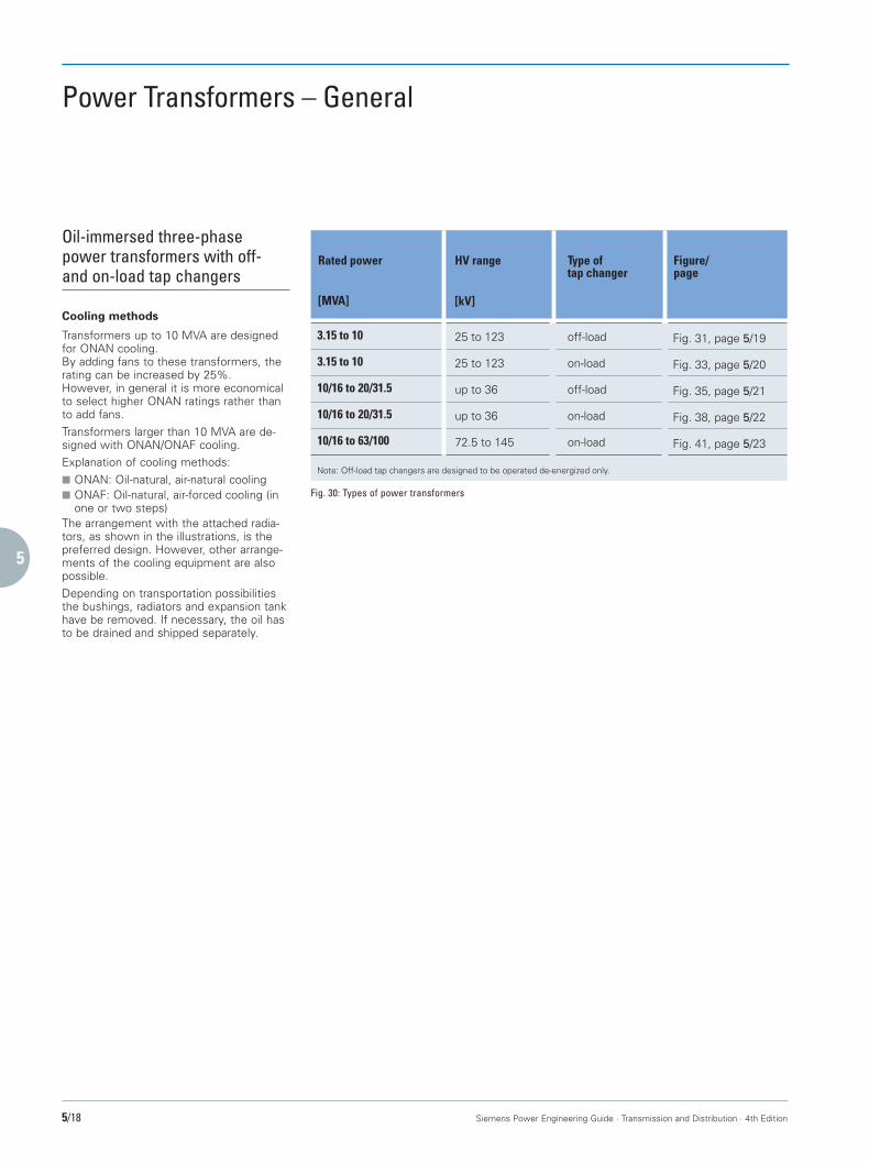
Fig. 30: Types of power transformers
Oil-immersed three-phasepower transformers with off-and on-load tap changers
Cooling methods
Transformers up to 10 MVA are designedfor ONAN cooling.By adding fans to these transformers, therating can be increased by 25%.However, in general it is more economicalto select higher ONAN ratings rather thanto add fans.Transformers larger than 10 MVA are de-signed with ONAN/ONAF cooling.Explanation of cooling methods:■ ONAN: Oil-natural, air-natural cooling■ ONAF: Oil-natural, air-forced cooling (in
one or two steps)The arrangement with the attached radia-tors, as shown in the illustrations, is thepreferred design. However, other arrange-ments of the cooling equipment are alsopossible.Depending on transportation possibilitiesthe bushings, radiators and expansion tankhave be removed. If necessary, the oil hasto be drained and shipped separately.
Ohne Namen-1 22.09.1999, 16:23 Uhr18

1
2
3
4
5
6
7
8
9
10
Siemens Power Engineering Guide · Transmission and Distribution · 4th Edition 5/19
Power Transformers – Selection TablesTechnical Data, Dimensions and Weights
E
H
EW
L
Oil-immersed three-phasepower transformers withoff-load tap changer3 150–10 000 kVA,HV rating: up to 123 kV
■ Taps onHV side: ± 2 x 2.5 %
■ Rated frequency: 50 Hz■ Impedance 6-10 %
voltage:■ Connection: HV winding: star-
delta connectionalternatively availableup to 24 kVLV winding:star or delta
3150
4000
LV rating No-loadloss
DimensionsL/W/H
Rated power HV rating Load lossat 75 °C
Totalweight
Oilweight
E
5000
6300
8000
10000
[kW]
28
33
35
38
41
46
45
48
53
54
56
62
63
65
72
2800/1850/2870
3200/2170/2940
3100/2300/3630
2550/2510/3020
3150/2490/3730
4560/2200/4540
2550/2840/3200
3200/2690/3080
4780/2600/4540
2580/2770/3530
3250/2850/4000
4880/2630/4590
2670/2900/3720
4060/2750/4170
4970/2900/4810
1600
1900
3100
2300
3300
6300
2500
3700
6600
3300
4200
7300
3900
4700
8600
[mm]
1070
1070
1070
1070
1070
1505
1505
1505
1505
1505
1505
1505
1505
1505
1505
[kVA]ONAN
[kV] [kV] [kW] [kg] [kg] [mm]
6.1–36
7.8–36
50–72.5
9.5–36
50–72.5
90–123
12.2–36
50–72.5
90–123
12.2–36
50–72.5
90–123
15.2–36
50–72.5
90–123
3–24
3–24
3–24
4–24
4–24
5–36
5–24
5–24
5–36
5–24
5–24
5–36
6–24
6–24
5–36
4.6
5.5
6.8
6.5
8.0
9.8
7.7
9.3
11.0
9.4
11.0
12.5
11.0
12.5
14.0
7200
8400
10800
9800
12200
17500
11700
13600
18900
14000
15900
21500
16600
18200
25000
Fig. 32
Fig. 31
Ohne Namen-1 22.09.1999, 16:23 Uhr19

1
2
3
4
5
6
7
8
9
10
5/20 Siemens Power Engineering Guide · Transmission and Distribution · 4th Edition
Power Transformers – Selection TablesTechnical Data, Dimensions and Weights
Oil-immersed three-phasepower transformerswith on-load tap changer3 150–10 000 kVA,HV rating: up to 123 kV
■ Taps on ± 16 % in ± 8 stepsHV side: of 2 %
■ Rated frequency: 50 Hz■ Impedance 6–10 %
voltage:■ Connection: HV winding: star
LV winding:star or delta
Fig. 33
10.9–36
9.2–36
50–72.5
11.5–36
50–72.5
90–123
14.4–36
50–72.5
90–123
18.3–36
50–72.5
90–123
22.9–36
50–72.5
90–123
kW
29
35
37
40
43
49
47
50
56
57
59
65
66
68
76
3400/2300/2900
3500/2700/3000
4150/2350/3600
3600/2400/3200
4200/2700/3700
5300/2700/4650
3700/2700/3300
4300/2900/3850
5600/2900/4650
3850/2500/3500
4600/2800/4050
5650/2950/4650
4400/2600/3650
5200/2850/4100
5750/2950/4700
2300
2600
4100
3100
4500
8000
3600
5000
8500
4500
6000
9000
5200
6500
10250
[mm]
1070
1070
1070
1070
1070
1505
1505
1505
1505
1505
1505
1505
1505
1505
1505
[kVA]ONAN
[kV] [kV] [kW] [kg] [kg] [mm]
3–24
3–24
4–24
4–24
5–24
5–36
5–24
5–24
5–36
5–24
5–24
5–36
6–24
6–24
5–36
4.8
5.8
7.1
6.8
8.4
9.8
8.1
9.8
11.5
9.9
11.5
13.1
11.5
13.1
14.7
9100
10300
13700
12300
15200
21800
14000
17000
23000
17000
19700
25500
20000
22500
29500
3150
4000
5000
6300
8000
10000
Rated power LV rating No-loadloss
HV rating Load lossat 75 °C
DimensionsL/W/H
Totalweight
Oilweight
E
Fig. 34
E
H
EW
L
Ohne Namen-1 22.09.1999, 16:23 Uhr20
1
2
3
4
5
6
7
8
9
10
Siemens Power Engineering Guide · Transmission and Distribution · 4th Edition 5/21
Power Transformers – Selection TablesTechnical Data, Dimensions and Weights
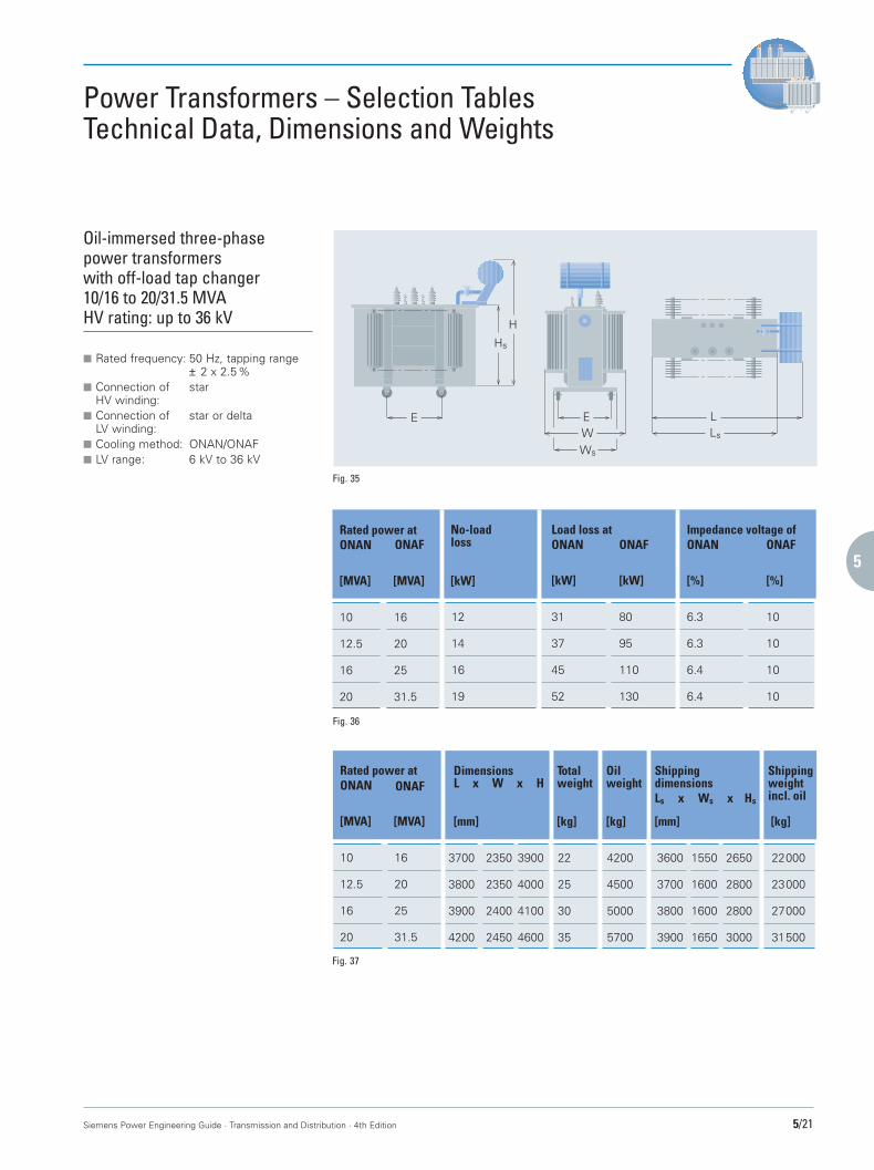
Oil-immersed three-phasepower transformerswith off-load tap changer10/16 to 20/31.5 MVAHV rating: up to 36 kV
■ Rated frequency: 50 Hz, tapping range± 2 x 2.5%
■ Connection of starHV winding:
■ Connection of star or deltaLV winding:
■ Cooling method: ONAN/ONAF■ LV range: 6 kV to 36 kV
Fig. 35
Fig. 36
Fig. 37
E
H
EW
LLs
Ws
Hs
[kW]
No-loadloss
12
14
16
19
Load loss atONAN
[kW] [kW]
ONAF
31
37
45
52
80
95
110
130
Impedance voltage ofONAN ONAF
[%] [%]
6.3
6.3
6.4
6.4
10
10
10
10
[MVA]
Rated power atONAN
[MVA]
10
12.5
16
20
16
20
25
31.5
ONAF
L x W x HShippingweightincl. oil
[MVA]
Rated power atONAN
[MVA]
ONAF
10
12.5
16
20
16
20
25
31.5
[kg][mm]
Totalweight
Dimensions
3700
3800
3900
4200
22
25
30
35
[mm] [kg]
2350
2350
2400
2450
3900
4000
4100
4600
[kg]
Oilweight
4200
4500
5000
5700
22000
23000
27000
31500
3600
3700
3800
3900
1550
1600
1600
1650
2650
2800
2800
3000
ShippingdimensionsLs x Ws x Hs
Ohne Namen-1 22.09.1999, 16:23 Uhr21

1
2
3
4
5
6
7
8
9
10
5/22 Siemens Power Engineering Guide · Transmission and Distribution · 4th Edition
Power Transformers – Selection TablesTechnical Data, Dimensions and Weights
Oil-immersed three-phasepower transformerwith on-load tap changer10/16 to 20/31.5 MVA,HV rating: up to 36 kV
■ Rated frequency: 50 Hz, tapping range± 16% in ± 9 steps
■ Connection of starHV winding:
■ Connection of star or deltaLV winding:
■ Cooling method: ONAN/ONAF■ LV range: 6 kV to 36 kV
Fig. 38
Fig. 39
Fig. 40
Ls
H
Ws
WL
Hs
10
12.5
16
20
16
20
25
31.5
12
14
16
19
31
37
45
52
80
95
111
130
6.3
6.3
6.4
6.4
10
10
10
10
[kW]
No-loadloss
Load loss atONAN
[kW] [kW]
ONAFImpedance voltage ofONAN ONAF
[%] [%][MVA]
Rated power atONAN
[MVA]
ONAF
4800
4900
5050
5300
27000
30000
34000
41000
2450
2500
2500
2550
3900
4000
4100
4600
6200
6700
7000
9000
24000
27000
31000
37000
4400
4500
4650
5000
1550
1600
1650
1700
2600
2650
2650
3000
L x W x HShippingweightincl. oil
[MVA]
Rated power atONAN
[MVA]
ONAF
[kg][mm]
Totalweight
Dimensions
[mm] [kg][kg]
Oilweight
ShippingdimensionsLs x Ws x Hs
10
12.5
16
20
16
20
25
31.5
Ohne Namen-1 22.09.1999, 16:24 Uhr22
1
2
3
4
5
6
7
8
9
10
Siemens Power Engineering Guide · Transmission and Distribution · 4th Edition 5/23
Power Transformers – Selection TablesTechnical Data, Dimensions and Weights
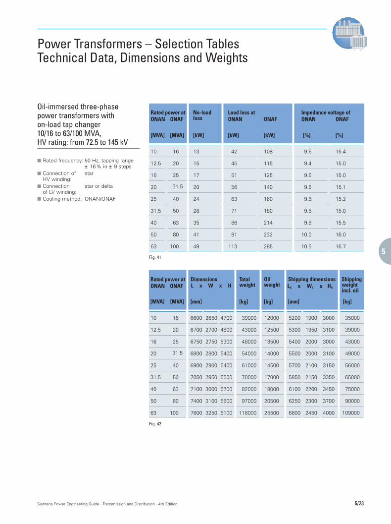
Oil-immersed three-phasepower transformers withon-load tap changer10/16 to 63/100 MVA,HV rating: from 72.5 to 145 kV
■ Rated frequency: 50 Hz, tapping range± 16% in ± 9 steps
■ Connection of starHV winding:
■ Connection star or deltaof LV winding:
■ Cooling method: ONAN/ONAF
Fig. 41
Fig. 42
[kW][MVA]
Rated power atONAN
No-loadloss
[MVA]
ONAF
10
12.5
16
20
25
31.5
40
50
63
31.5
13
15
17
20
24
28
35
41
49
Load loss atONAN
[kW] [kW]
ONAF
42
45
51
56
63
71
86
91
113
108
115
125
140
160
180
214
232
285
Impedance voltage ofONAN ONAF
[%] [%]
9.6
9.4
9.6
9.6
9.5
9.5
9.8
10.0
10.5
15.4
15.0
15.0
15.1
15.2
15.0
15.5
16.0
16.7
16
20
25
40
50
63
80
100
L x W x HShippingweightincl. oil
[kg][MVA] [mm]
Rated power atONAN ONAF
Totalweight
Dimensions
10
12.5
16
20
25
31.5
40
50
63
6600
6700
6750
6800
6900
7050
7100
7400
7800
39000
43000
48000
54000
61000
70000
82000
97000
118000
Ls x Ws x Hs
[mm] [kg]
2650
2700
2750
2800
2900
2950
3000
3100
3250
4700
4800
5300
5400
5400
5500
5700
5800
6100
[kg]
Oilweight
12000
12500
13500
14000
14500
17000
18000
20500
25500
35000
39000
43000
49000
56000
65000
75000
90000
109000
5200
5300
5400
5500
5700
5850
6100
6250
6800
1900
1950
2000
2000
2100
2150
2200
2300
2450
3000
3100
3000
3100
3150
3350
3450
3700
4000
Shipping dimensions
31.5
16
20
25
40
50
63
80
100
[MVA]
Ohne Namen-1 22.09.1999, 16:24 Uhr23

1
2
3
4
5
6
7
8
9
10
5/24 Siemens Power Engineering Guide · Transmission and Distribution · 4th Edition
Fig. 44: View into an 850/1100-MVA generator transformer
Fig. 43: Coal-fired power station in Germany with two 850-MVA generator transformers:Low-noise design, extended setting range and continuous overload capacity up to 1100 MVA
Power Transformersabove 100 MVA
The power rating range above 100 MVAcomprises mainly generator transformersand system-interconnecting transformerswith off-load and/or on-load tap changers.Depending on the on-site requirements, theycan be designed as transformers with sepa-rate windings or as autotransformers, three-or single-phase, for power ratings up to over1000 MVA and voltages up to 1500 kV.We manufacture these units according toIEC 76, VDE 0532 or other national specifi-cations.Offers for transformers larger than 100 MVAonly on request.
12
8
10
1
913
23
45
7
6
11
1 Five-limb core2 LV winding3 HV winding4 Tapped winding5 Tap leads6 LV bushings7 HV bushings8 Clamping frame9 On-load tap changer
10 Motor drive11 Schnabel-car-tank12 Conservator13 Water-cooling system
Ohne Namen-1 22.09.1999, 16:24 Uhr24

1
2
3
4
5
6
7
8
9
10
Siemens Power Engineering Guide · Transmission and Distribution · 4th Edition 5/25
Fig. 45: An integrated solution – the complete Monitoring System housed in a cubicle of the transformer itself
Power TransformersMonitoring System
Siemens Monitoring System:Efficient Condition Recordingand Diagnosis for Power Trans-formers
Complete acquisition and evaluation of upto 45 measured variables, automatic trendanalysis, diagnosis and early warning – thenew Siemens Monitoring System makesuse of all possible ways of monitoringpower transformers: Round the clock, withprecision sensors for voltage, temperatureor quality of insulation, and with powerfulsoftware for measured data processing,display or documentation – with on-linecommunication over any distance.Maintenance and utilization of power trans-formers are made more efficient all-round.Because the comprehensive informationprovided on the condition of the equipmentand auxiliaries ensures that maintenance iscarried out just where it's needed, costlyroutine inspections are a thing of the past.And because the maintenance is alwayspreventive, faults are reliably ruled out.All these advantages enhance availability –and thus ensure a long service life of yourpower transformers. This applies equally tonew and old transformers.Equipping new transformers with theSiemens Monitoring System ensures thatright from the start the user is in posses-sion of all essential data–for quick, compre-hensive analysis. And retrofitting on trans-formers already in service for considerableperiods pays off as well.Particularly in the case of old transformers,constant monitoring significantly reducesthe growing risk of failure.Offers for transformers larger 100 MVAonly on request.
Ohne Namen-1 22.09.1999, 16:25 Uhr25

1
2
3
4
5
6
7
8
9
10
5/26 Siemens Power Engineering Guide · Transmission and Distribution · 4th Edition
On-load Tap Changers
The on-load tap changers installed inSiemens power transformers are manufac-tured by Maschinenfabrik Reinhausen (MR).MR is a supplier of technically advancedon-load tap changers for oil-immersedpower transformers covering an applicationrange from 100 A to 4,500 A and up to420 kV. About 90,000 MR high-speed re-sistor-type tap changers are succesfully inservice worldwide.The great variety of tap changer models isbased on a modular system which is capa-ble of meeting the individual customer’sspecifications for the respective operatingconditions of the transformer. Dependingon the required application range selector,switches or diverter switches with tap se-lectors can be used, both available for neu-tral, delta or single-pole connection. Up to107 operating positions can be achieved bythe use of a multiple course tap selector.In addition to the well-known on-load tap-changer for installation in oil-immersedtransformers, MR offers also a standard-ized gas-insulated tap changer for indoorinstallation which will be mounted on dry-type transformers up to approx. 30 MVAand 36 kV, or SF6-type transformers up to40 MVA and 123 kV.The main characteristics of MRproducts are:■ Compact design■ Optimum adaption and economic
solutions offered by the great numberof variants
■ High reliability■ Long life■ Reduced maintenance■ Service friendlinessThe tap changers are mechanicallydriven – via the drive shafts and the bevelgear – by a motor drive attached to thetransformer tank. It is controlled accordingto the step-by-step principle. Electrical andmechanical safety devices prevent over-running of the end positions. Further safe-ty measures, such as the automatic restartfunction, a safety circuit to prevent falsephase sequence and running through posi-tions, ensure the reliable operation of mo-tor drives.
For operation under extremely onerousconditions an oil filter unit is availablefor filtering or filtering and drying of theswitching oil. Voltage monitoring is effect-ed by microprocessor-controlled operationcontrol systems or voltage regulatorswhich include a great variety of data inputand output facilities.In combination with a parallel control unit,several transformers connected in parallelcan be automatically controlled and moni-tored.Furthermore, Maschinenfabrik Reinhausenoffers a worldwide technical service tomaintain their high quality standard.Inspections at regular intervals with onlysmall maintenance requirements guaranteethe reliable operation expected with MRproducts.
Fig. 46: MR motor drive ED 100 S Fig. 47: Gas-insulated on-load tap changer
Fig. 48: Selection of on-load tap changers from the MR product range
Type VT
Type V Type H Type M Type G
Ohne Namen-1 22.09.1999, 16:25 Uhr26
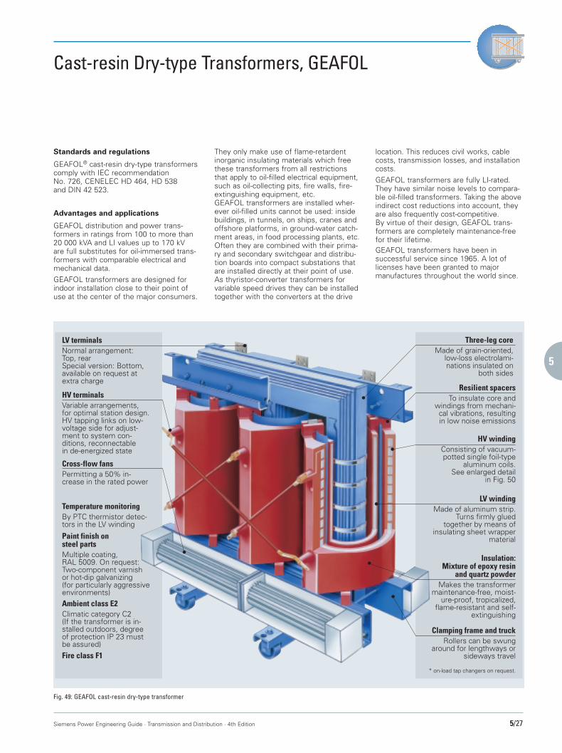
1
2
3
4
5
6
7
8
9
10
Siemens Power Engineering Guide · Transmission and Distribution · 4th Edition 5/27
* on-load tap changers on request.
HV windingConsisting of vacuum-potted single foil-type
aluminum coils.See enlarged detail
in Fig. 50
HV terminalsVariable arrangements,for optimal station design.HV tapping links on low-voltage side for adjust-ment to system con-ditions, reconnectablein de-energized state
Resilient spacersTo insulate core and
windings from mechani-cal vibrations, resultingin low noise emissions
LV windingMade of aluminum strip.
Turns firmly gluedtogether by means of
insulating sheet wrappermaterial
Cross-flow fansPermitting a 50% in-crease in the rated power
Temperature monitoringBy PTC thermistor detec-tors in the LV winding
Paint finish onsteel partsMultiple coating,RAL 5009. On request:Two-component varnishor hot-dip galvanizing(for particularly aggressiveenvironments)
Clamping frame and truckRollers can be swung
around for lengthways orsideways travel
Insulation:Mixture of epoxy resin
and quartz powderMakes the transformer
maintenance-free, moist-ure-proof, tropicalized,
flame-resistant and self-extinguishing
LV terminalsNormal arrangement:Top, rearSpecial version: Bottom,available on request atextra charge
Ambient class E2Climatic category C2(If the transformer is in-stalled outdoors, degreeof protection IP 23 mustbe assured)
Three-leg coreMade of grain-oriented,
low-loss electrolami-nations insulated on
both sides
Fire class F1
Cast-resin Dry-type Transformers, GEAFOL
Standards and regulations
GEAFOL® cast-resin dry-type transformerscomply with IEC recommendationNo. 726, CENELEC HD 464, HD 538and DIN 42 523.
Advantages and applications
GEAFOL distribution and power trans-formers in ratings from 100 to more than20 000 kVA and LI values up to 170 kVare full substitutes for oil-immersed trans-formers with comparable electrical andmechanical data.GEAFOL transformers are designed forindoor installation close to their point ofuse at the center of the major consumers.
They only make use of flame-retardentinorganic insulating materials which freethese transformers from all restrictionsthat apply to oil-filled electrical equipment,such as oil-collecting pits, fire walls, fire-extinguishing equipment, etc.GEAFOL transformers are installed wher-ever oil-filled units cannot be used: insidebuildings, in tunnels, on ships, cranes andoffshore platforms, in ground-water catch-ment areas, in food processing plants, etc.Often they are combined with their prima-ry and secondary switchgear and distribu-tion boards into compact substations thatare installed directly at their point of use.As thyristor-converter transformers forvariable speed drives they can be installedtogether with the converters at the drive
location. This reduces civil works, cablecosts, transmission losses, and installationcosts.GEAFOL transformers are fully LI-rated.They have similar noise levels to compara-ble oil-filled transformers. Taking the aboveindirect cost reductions into account, theyare also frequently cost-competitive.By virtue of their design, GEAFOL trans-formers are completely maintenance-freefor their lifetime.GEAFOL transformers have been insuccessful service since 1965. A lot oflicenses have been granted to majormanufactures throughout the world since.
Fig. 49: GEAFOL cast-resin dry-type transformer
Ohne Namen-1 22.09.1999, 16:25 Uhr27
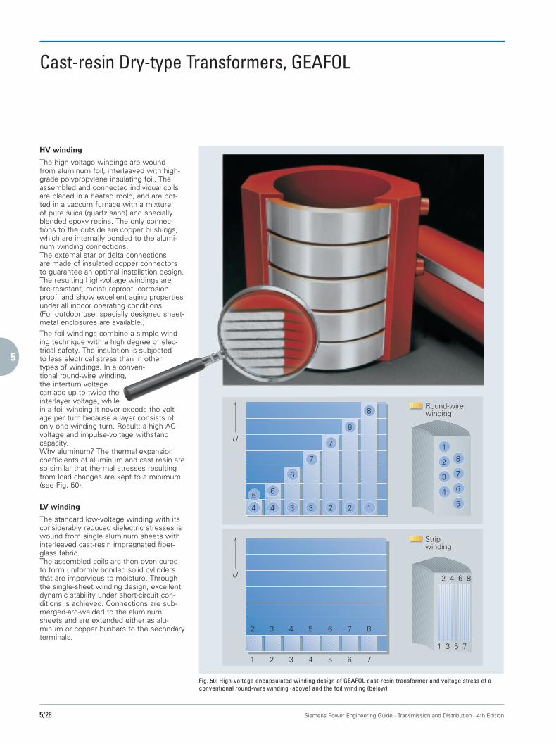
1
2
3
4
5
6
7
8
9
10
5/28 Siemens Power Engineering Guide · Transmission and Distribution · 4th Edition
Cast-resin Dry-type Transformers, GEAFOL
1
8
8
223344
5 6
6
7
7U
U
1 2 3 4 5 6 7
2 3 4 5 6 7 8
1
2
3
4
8
7
6
5
2 4 6 8
1 3 5 7
Round-wirewinding
Stripwinding
HV winding
The high-voltage windings are woundfrom aluminum foil, interleaved with high-grade polypropylene insulating foil. Theassembled and connected individual coilsare placed in a heated mold, and are pot-ted in a vaccum furnace with a mixtureof pure silica (quartz sand) and speciallyblended epoxy resins. The only connec-tions to the outside are copper bushings,which are internally bonded to the alumi-num winding connections.The external star or delta connectionsare made of insulated copper connectorsto guarantee an optimal installation design.The resulting high-voltage windings arefire-resistant, moistureproof, corrosion-proof, and show excellent aging propertiesunder all indoor operating conditions.(For outdoor use, specially designed sheet-metal enclosures are available.)The foil windings combine a simple wind-ing technique with a high degree of elec-trical safety. The insulation is subjectedto less electrical stress than in othertypes of windings. In a conven-tional round-wire winding,the interturn voltagecan add up to twice theinterlayer voltage, whilein a foil winding it never exeeds the volt-age per turn because a layer consists ofonly one winding turn. Result: a high ACvoltage and impulse-voltage withstandcapacity.Why aluminum? The thermal expansioncoefficients of aluminum and cast resin areso similar that thermal stresses resultingfrom load changes are kept to a minimum(see Fig. 50).
LV winding
The standard low-voltage winding with itsconsiderably reduced dielectric stresses iswound from single aluminum sheets withinterleaved cast-resin impregnated fiber-glass fabric.The assembled coils are then oven-curedto form uniformly bonded solid cylindersthat are impervious to moisture. Throughthe single-sheet winding design, excellentdynamic stability under short-circuit con-ditions is achieved. Connections are sub-merged-arc-welded to the aluminumsheets and are extended either as alu-minum or copper busbars to the secondaryterminals.
Fig. 50: High-voltage encapsulated winding design of GEAFOL cast-resin transformer and voltage stress of aconventional round-wire winding (above) and the foil winding (below)
Ohne Namen-1 22.09.1999, 16:25 Uhr28

1
2
3
4
5
6
7
8
9
10
Siemens Power Engineering Guide · Transmission and Distribution · 4th Edition 5/29
Cast-resin Dry-type Transformers, GEAFOL
Fire safety
GEAFOL transformers use only flame-retardent and self-extinguishing materialsin their construction. No additional sub-stances, such as aluminum oxide trihy-drate, which could negatively influencethe mechanical stability of the cast-resinmolding material, are used. Internal arcingfrom electrical faults and externally appliedflames do not cause the transformers toburst or burn. After the source of ignitionis removed, the transformer is self-extin-guishing. This design has been approvedby fire officials in many countries for instal-lation in populated buildings and otherstructures.The environmental safety of the combus-tion residues has been proven in manytests.
Categorization of cast-resintransformers
Dry-type transformers have to be cate-gorized under the sections listed below:■ Environmental category■ Climatic category■ Fire categoryThese categories have to be shown on therating plate of each dry-type transformer.
The properties laid down in the standardsfor ratings within the approximate categoryrelating to environment (humidity), climateand fire behavior have to be demonstratedby means of tests.These tests are described for the environ-mental category (code number E0, E1 andE2) and for the climatic category (codenumber C1, C2) in DIN VDE 0532 Part 6(corresponding to HD 464). According tothis standard, they are to be carried out oncomplete transformers.The tests of fire behavior (fire categorycode numbers F0 and F1) are limited totests on a duplication of a complete trans-former. It consists of a core leg, a low-volt-age winding and a high-voltage winding.The specifications for fire category F2 aredetermined by agreement between themanufacturer and the customer.Siemens have carried out a lot of tests.The results for our GEAFOL transformersare something to be proud of:■ Environmental category E2■ Climatic category C2■ Fire category F1This good behavior is solely due to theGEAFOL cast-resin mix which has beenused successfully for decades.
Insulation class and temperature rise
The high-voltage winding and the low-voltage winding utilize class F insulatingmaterials with a mean temperature riseof 100 K (standard design).
Overload capability
GEAFOL transformers can be overloadedpermanently up to 50% (with a corre-sponding increase in impedance voltage)if additional radial cooling fans are installed.(Dimensions increase by approximately200 mm in length and width.) Short-timeoverloads are uncritical as long as themaximum winding temperatures are notexceeded for extended periods of time.
Temperature monitoring
Each GEAFOL transformer is fitted withthree temperature sensors installed inthe LV winding, and a solid-state trippingdevice with relay output. The PTC thermis-tors used for sensing are selected for theapplicable maximum hot-spot winding tem-perature. Additional sets of sensors withlower temperature points can be installedfor them and for fan control purposes. Ad-ditional dial-type thermometers and Pt100are available, too. For operating voltagesof the LV winding of 3.6 kV and higher,special temperature measuring equipmentcan be provided.Auxiliary wiring is run in protective conduitand terminated in a central LV terminalbox (optional). Each wire and terminal isidentified, and a wiring diagram is perma-nently attached to the inside cover of thisterminal box.
Installation and enclosures
Indoor installation in electrical operatingrooms or in various sheet-metal enclosuresis the preferred method of installation.The transformers need only be protectedagainst access to the terminals or thewinding surfaces, against direct sunlight,and against water. Sufficient ventilationmust be provided by the installation loca-tion or the enclosure. Otherwise forced-aircooling must be specified or provided byothers.
Fig. 51: Flammability test of cast-resin transformer
Ohne Namen-1 22.09.1999, 16:25 Uhr29

1
2
3
4
5
6
7
8
9
10
5/30 Siemens Power Engineering Guide · Transmission and Distribution · 4th Edition
Cast-resin Dry-type Transformers, GEAFOL
Instead of the standard open terminals,insulated plug-type elbow connectors canbe supplied for the high-voltage side withLI ratings up to 170 kV. Primary cables areusually fed to the transformer from trench-es below, but can also be connected fromabove.Secondary connections can be made bymultiple insulated cables, or by busbars,from either below or above. Secondaryterminals are either aluminum or copperbusbar stubs, drilled to specification.A variety of indoor and outdoor enclosuresin different protection classes are availablefor the transformers alone, or for indoorcompact substations in conjunction withhigh- and low-voltage switchgear cubicles.
Recycling of GEAFOL transformers
Of all the GEAFOL transformers manufac-tured since 1965, even the oldest units arenot about to reach the end of their servicelife expectancy. In spite of this, a lot ofexperiences have been made over theyears with the recycling of coils that havebecome unusable due to faulty manufac-ture or damage. These experiences showthat all the metallic components, i.e. ap-prox. 90% of all materials, can be fully re-covered economically. The recycling meth-od used by Siemens does not pollute theenvironment. In view of the value of thesecondary raw materials, the procedurecan be economical even considering thecurrently small amounts.
Fig. 53: Radial cooling fans on GEAFOL transformer for AF cooling
Fig. 52: GEAFOL transformer with plug-type cable connections
Fig. 54: GEAFOL transformer in protective housing to IP 20/40
Ohne Namen-1 22.09.1999, 16:26 Uhr30

1
2
3
4
5
6
7
8
9
10
Siemens Power Engineering Guide · Transmission and Distribution · 4th Edition 5/31
GEAFOL Cast-resin Selection Tables,Technical Data, Dimensions and Weights
Um LJ AC
1.1
12
24
36
[kV] [kV] [kV]
–
75
95**
145**
3
28
50
70
E
H1
2U 2V 2W
A1EB1
2N
■ Standard: DIN 42523■ Rated power: 100–20000 kVA*■ Rated frequency: 50 Hz■ HV rating: up to 36 kV■ LV rating: up to 780 V;
special designsfor up to 12 kV arepossible
■ Tappings on ± 2.5% or ± 2 x 2.5%HV side:
■ Connection: HV winding: deltaLV winding: star
■ Impedance 4–8%voltage at ratedcurrent:
■ Insulation class: HV/LV = F/F■ Temperature HV/LV = 100/100 K
rise:■ Color of metal RAL 5009 (other
parts: colors are available)
Soundpowerlevel
LWA[dB]
Distancebetweenwheelcenters
E[mm]
Totalweight
Length Width Height
GGES[kg]
A1[mm]
B1[mm]
H1[mm]
Dimensions
* In case of short-circuits at 75 °C** In case of short-circuits at 120 °C
45
37
45
37
45
37
45
37
47
39
47
39
47
39
47
39
12
24
12
24
4
4
6
6
4
4
6
6
4
4
6
6
4
4
6
6
.5044-3CA
.5044-3GA
.5044-3DA
.5044-3HA
.5064-3CA
.5064-3GA
.5064-3DA
.5064-3HA
.5244-3CA
.5244-3GA
.5244-3DA
.5244-3HA
.5264-3CA
.5264-3GA
.5264-3DA
.5264-3HA
440
320
360
300
600
400
420
330
610
440
500
400
800
580
600
480
59
51
59
51
59
51
59
51
62
54
62
54
62
54
62
54
without wheels
without wheels
without wheels
without wheels
without wheels
without wheels
without wheels
without wheels
520
520
520
520
520
520
520
520
630
760
590
660
750
830
660
770
770
920
750
850
910
940
820
900
1210
1230
1190
1230
1310
1300
1250
1300
1220
1290
1270
1300
1330
1310
1310
1350
705
710
705
710
755
755
750
755
710
720
720
725
725
720
725
765
835
890
860
855
935
940
915
930
1040
1050
990
985
1090
1095
1075
1060
1600
1600
2000
2000
1500
1500
1800
1800
2300
2300
2300
2300
2200
2200
2500
2500
Ratedpower
Sn[kVA]
Ratedvoltage
Um[kV]
Impe-dancevoltage
U2[%]
Type No-loadlosses
P0[W]
LPA[dB]
Loadlosses
Pk 75*[W]4GB…
Rated power figures in parentheses are not standardized.
1900
1900
2300
2300
1750
1750
2050
2050
2600
2600
2700
2700
2500
2500
2900
2900
Loadlosses
Pk 120**[W]
100
160
Dimensions and weights are approximate values and valid for 400 V on the secondary side, vector-group can be Dyn 5 or Dyn 11.
Soundpress.level1 mtoler-ance+ 3 dB
Fig. 56: GEAFOL cast-resin transformer
Fig. 55: Insulation level
Fig. 57: GEAFOL cast-resin transformers 50 to 2500 kVA
* power rating > 2.5 MVA upon request** other levels upon request
Ohne Namen-1 22.09.1999, 16:26 Uhr31

1
2
3
4
5
6
7
8
9
10
5/32 Siemens Power Engineering Guide · Transmission and Distribution · 4th Edition
GEAFOL Cast-resin Selection Tables,Technical Data, Dimensions and Weights
Fig. 58: GEAFOL cast-resin transformers 50 to 2500 kVA
(315)
Soundpowerlevel
LWA[dB]
Distancebetweenwheelcenters
E[mm]
Totalweight
Length Width Height
GGES[kg]
A1[mm]
B1[mm]
H1[mm]
Dimensions
* In case of short-circuits at 75 °C** In case of short-circuits at 120 °C
50
42
50
42
50
41
50
41
50
52
43
51
43
51
43
51
43
51
52
44
52
44
52
44
52
44
52
53
45
53
45
53
44
53
45
53
12
24
36
12
24
36
12
24
36
12
24
36
4
4
6
6
4
4
6
6
6
4
4
6
6
4
4
6
6
6
4
4
6
6
4
4
6
6
6
4
4
6
6
4
4
6
6
6
.5444-3CA
.5444-3GA
.5444-3DA
.5444-3HA
.5464-3CA
.5464-3GA
.5464-3DA
.5464-3HA
.5475-3DA
.5544-3CA
.5544-3GA
.5544-3DA
.5544-3HA
.5564-3CA
.5564-3GA
.5564-3DA
.5564-3HA
.5575-3DA
.5644-3CA
.5644-3GA
.5644-3DA
.5644-3HA
.5664-3CA
.5664-3GA
.5664-3DA
.5664-3HA
.5675-3DA
.5744-3CA
.5744-3GA
.5744-3DA
.5744-3HA
.5764-3CA
.5764-3GA
.5764-3DA
.5764-3HA
.5775-3DA
820
600
700
570
1050
800
880
650
1300
980
720
850
680
1250
930
1000
780
1450
1150
880
1000
820
1450
1100
1200
940
1700
1350
1000
1200
980
1700
1270
1400
1100
1900
65
57
65
57
65
57
65
57
65
67
59
67
59
67
59
67
59
67
68
60
68
60
68
60
68
60
68
69
61
69
61
69
61
69
61
69
520
520
520
520
520
520
520
520
520
670
670
670
670
670
670
670
670
670
670
670
670
670
670
670
670
670
670
670
670
670
670
670
670
670
670
670
1040
1170
990
1120
1190
1230
990
1180
1700
1160
1320
1150
1290
1250
1400
1190
1300
1900
1310
1430
1250
1350
1410
1570
1350
1460
2100
1520
1740
1470
1620
1620
1830
1580
1720
2600
1330
1330
1350
1390
1390
1400
1360
1430
1900
1370
1380
1380
1410
1410
1440
1410
1460
1950
1380
1380
1410
1430
1440
1460
1480
1480
2000
1410
1450
1460
1490
1500
1540
1540
1560
2050
730
730
740
745
735
735
735
745
900
820
820
830
830
820
825
825
830
920
820
820
825
830
825
830
835
835
920
830
835
845
845
835
840
850
850
940
1110
1135
1065
1090
1120
1150
1140
1160
1350
1125
1195
1140
1165
1195
1205
1185
1195
1400
1265
1290
1195
1195
1280
1280
1275
1280
1440
1320
1345
1275
1290
1330
1350
1305
1320
1500
250 3000
3000
2900
2900
2900
2900
3100
3100
3800
3300
3300
3400
3400
3400
3400
3600
3600
4500
4300
4300
4300
4300
3900
3900
4100
4100
5100
4900
4900
5600
5600
4800
4800
5000
5000
6000
Ratedpower
Sn[kVA]
Ratedvoltage
Um[kV]
Impe-dancevoltage
U2[%]
Type No-loadlosses
P0[W]
LPA[dB]
Loadlosses
Pk 75*[W]4GB…
Rated power figures in parentheses are not standardized.
3500
3400
3300
3300
3300
3300
3600
3600
4370
3800
3800
3900
3900
3900
3900
4100
4100
5170
4900
4900
4900
4900
4500
4500
4700
4700
5860
5600
5600
6400
6400
5500
5500
5700
5700
6900
Loadlosses
Pk 120**[W]
Dimensions and weights are approximate values and valid for 400 V on the secondary side, vector-group can be Dyn 5 or Dyn 11.
Soundpress.level1 mtoler-ance+ 3 dB
400
(500)
Ohne Namen-1 22.09.1999, 16:26 Uhr32
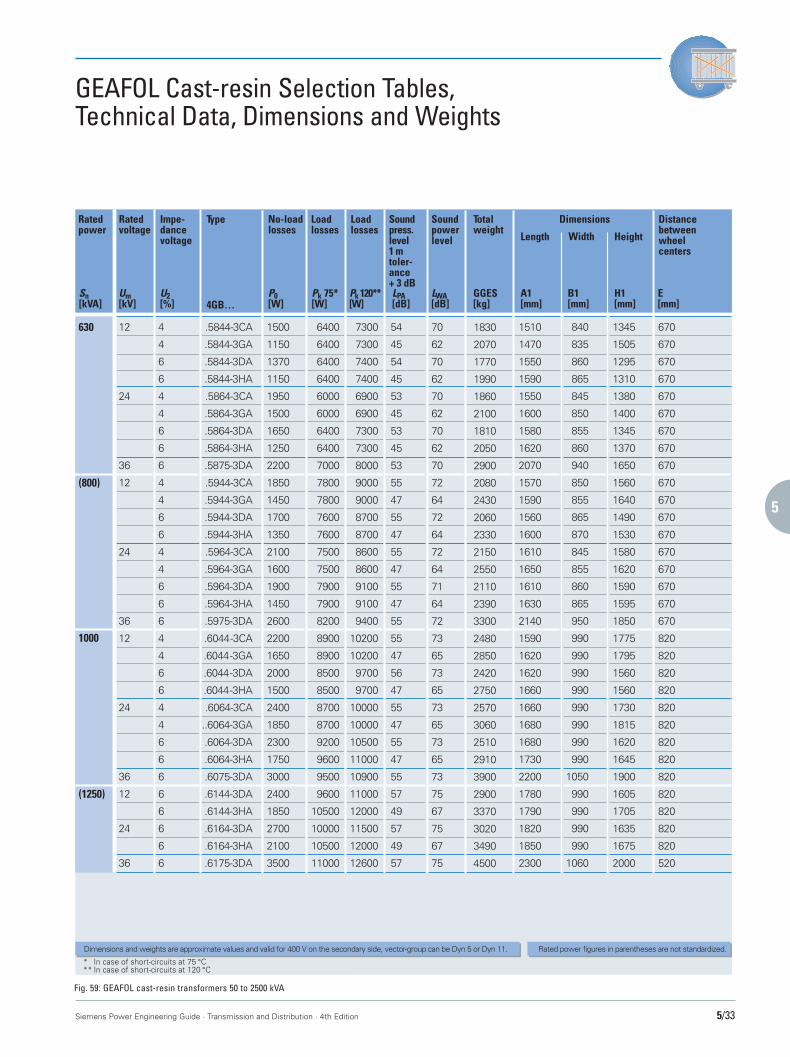
1
2
3
4
5
6
7
8
9
10
Siemens Power Engineering Guide · Transmission and Distribution · 4th Edition 5/33
GEAFOL Cast-resin Selection Tables,Technical Data, Dimensions and Weights
Soundpowerlevel
LWA[dB]
Distancebetweenwheelcenters
E[mm]
Totalweight
Length Width Height
GGES[kg]
A1[mm]
B1[mm]
H1[mm]
Dimensions
(800)
* In case of short-circuits at 75 °C** In case of short-circuits at 120 °C
54
45
54
45
53
45
53
45
53
55
47
55
47
55
47
55
47
55
55
47
56
47
55
47
55
47
55
57
49
57
49
57
12
24
36
12
24
36
12
24
36
12
24
36
4
4
6
6
4
4
6
6
6
4
4
6
6
4
4
6
6
6
4
4
6
6
4
4
6
6
6
6
6
6
6
6
.5844-3CA
.5844-3GA
.5844-3DA
.5844-3HA
.5864-3CA
.5864-3GA
.5864-3DA
.5864-3HA
.5875-3DA
.5944-3CA
.5944-3GA
.5944-3DA
.5944-3HA
.5964-3CA
.5964-3GA
.5964-3DA
.5964-3HA
.5975-3DA
.6044-3CA
.6044-3GA
.6044-3DA
.6044-3HA
.6064-3CA
..6064-3GA
.6064-3DA
.6064-3HA
.6075-3DA
.6144-3DA
.6144-3HA
.6164-3DA
.6164-3HA
.6175-3DA
1500
1150
1370
1150
1950
1500
1650
1250
2200
1850
1450
1700
1350
2100
1600
1900
1450
2600
2200
1650
2000
1500
2400
1850
2300
1750
3000
2400
1850
2700
2100
3500
70
62
70
62
70
62
70
62
70
72
64
72
64
72
64
71
64
72
73
65
73
65
73
65
73
65
73
75
67
75
67
75
670
670
670
670
670
670
670
670
670
670
670
670
670
670
670
670
670
670
820
820
820
820
820
820
820
820
820
820
820
820
820
520
1830
2070
1770
1990
1860
2100
1810
2050
2900
2080
2430
2060
2330
2150
2550
2110
2390
3300
2480
2850
2420
2750
2570
3060
2510
2910
3900
2900
3370
3020
3490
4500
1510
1470
1550
1590
1550
1600
1580
1620
2070
1570
1590
1560
1600
1610
1650
1610
1630
2140
1590
1620
1620
1660
1660
1680
1680
1730
2200
1780
1790
1820
1850
2300
840
835
860
865
845
850
855
860
940
850
855
865
870
845
855
860
865
950
990
990
990
990
990
990
990
990
1050
990
990
990
990
1060
1345
1505
1295
1310
1380
1400
1345
1370
1650
1560
1640
1490
1530
1580
1620
1590
1595
1850
1775
1795
1560
1560
1730
1815
1620
1645
1900
1605
1705
1635
1675
2000
630 6400
6400
6400
6400
6000
6000
6400
6400
7000
7800
7800
7600
7600
7500
7500
7900
7900
8200
8900
8900
8500
8500
8700
8700
9200
9600
9500
9600
10500
10000
10500
11000
7300
7300
7400
7400
6900
6900
7300
7300
8000
9000
9000
8700
8700
8600
8600
9100
9100
9400
10200
10200
9700
9700
10000
10000
10500
11000
10900
11000
12000
11500
12000
12600
Ratedpower
Sn[kVA]
Ratedvoltage
Um[kV]
Impe-dancevoltage
U2[%]
Type No-loadlosses
P0[W]
LPA[dB]
Loadlosses
Pk 75*[W]4GB…
Rated power figures in parentheses are not standardized.
Loadlosses
Pk 120**[W]
Dimensions and weights are approximate values and valid for 400 V on the secondary side, vector-group can be Dyn 5 or Dyn 11.
Soundpress.level1 mtoler-ance+ 3 dB
(1250)
1000
Fig. 59: GEAFOL cast-resin transformers 50 to 2500 kVA
Ohne Namen-1 22.09.1999, 16:26 Uhr33
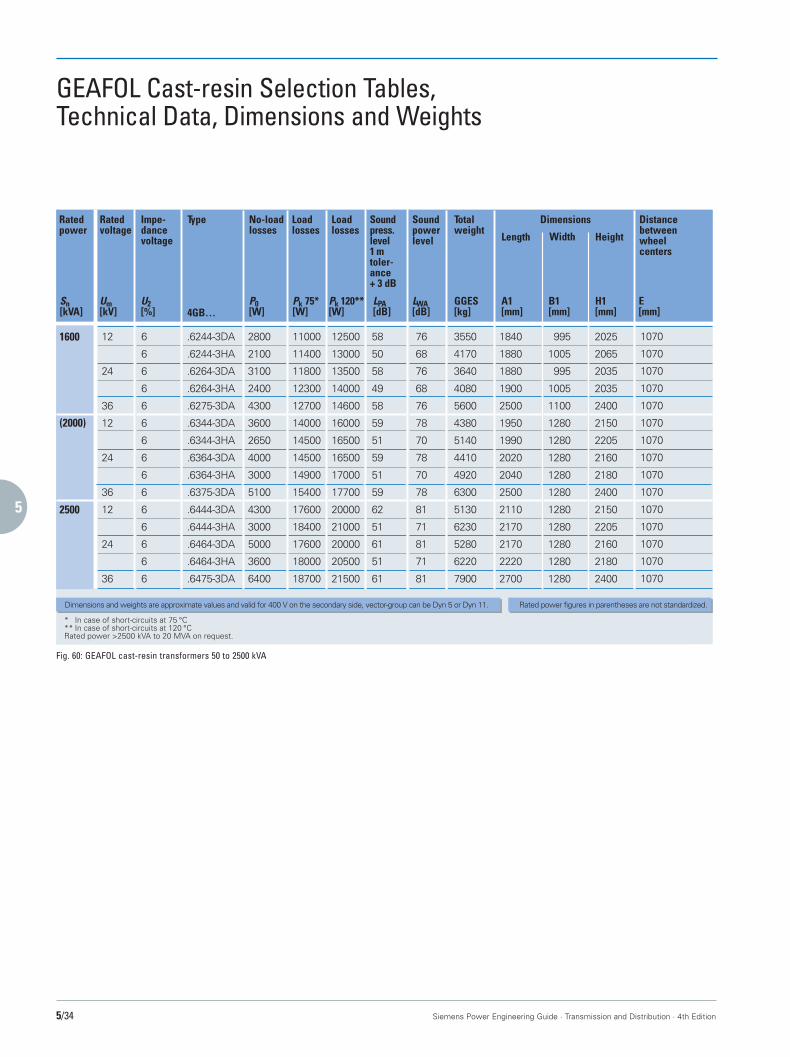
1
2
3
4
5
6
7
8
9
10
5/34 Siemens Power Engineering Guide · Transmission and Distribution · 4th Edition
GEAFOL Cast-resin Selection Tables,Technical Data, Dimensions and Weights
Soundpowerlevel
LWA[dB]
Distancebetweenwheelcenters
E[mm]
Totalweight
Length Width Height
GGES[kg]
A1[mm]
B1[mm]
H1[mm]
Dimensions
(2000)
2500
* In case of short-circuits at 75 °C** In case of short-circuits at 120 °CRated power >2500 kVA to 20 MVA on request.
58
50
58
49
58
59
51
59
51
59
62
51
61
51
61
12
24
36
12
24
36
12
24
36
6
6
6
6
6
6
6
6
6
6
6
6
6
6
6
.6244-3DA
.6244-3HA
.6264-3DA
.6264-3HA
.6275-3DA
.6344-3DA
.6344-3HA
.6364-3DA
.6364-3HA
.6375-3DA
.6444-3DA
.6444-3HA
.6464-3DA
.6464-3HA
.6475-3DA
2800
2100
3100
2400
4300
3600
2650
4000
3000
5100
4300
3000
5000
3600
6400
76
68
76
68
76
78
70
78
70
78
81
71
81
71
81
1070
1070
1070
1070
1070
1070
1070
1070
1070
1070
1070
1070
1070
1070
1070
3550
4170
3640
4080
5600
4380
5140
4410
4920
6300
5130
6230
5280
6220
7900
1840
1880
1880
1900
2500
1950
1990
2020
2040
2500
2110
2170
2170
2220
2700
995
1005
995
1005
1100
1280
1280
1280
1280
1280
1280
1280
1280
1280
1280
2025
2065
2035
2035
2400
2150
2205
2160
2180
2400
2150
2205
2160
2180
2400
1600 11000
11400
11800
12300
12700
14000
14500
14500
14900
15400
17600
18400
17600
18000
18700
12500
13000
13500
14000
14600
16000
16500
16500
17000
17700
20000
21000
20000
20500
21500
Ratedpower
Sn[kVA]
Ratedvoltage
Um[kV]
Impe-dancevoltage
U2[%]
Type No-loadlosses
P0[W]
LPA[dB]
Loadlosses
Pk 75*[W]4GB…
Rated power figures in parentheses are not standardized.
Loadlosses
Pk 120**[W]
Dimensions and weights are approximate values and valid for 400 V on the secondary side, vector-group can be Dyn 5 or Dyn 11.
Soundpress.level1 mtoler-ance+ 3 dB
Fig. 60: GEAFOL cast-resin transformers 50 to 2500 kVA
Ohne Namen-1 22.09.1999, 16:26 Uhr34

1
2
3
4
5
6
7
8
9
10
Siemens Power Engineering Guide · Transmission and Distribution · 4th Edition 5/35
Special Transformers
GEAFOL cast-resin transformerswith oil-free tap-changers
The voltage-regulating cast-resin trans-formers connected on the load side of themedium-voltage power supply system feedthe plant-side distribution transformers.The tap-changer-controlled transformersused in these medium-voltage systemsneed to have appropriately high ratings.Siemens offers suitable transformers in itsGEAFOL design which has proved suc-cessful over many years and is available inratings of up to 20 MVA. With forced cool-ing it is even possible to increase the pow-er ratings still further by 40%. The range ofrated voltage extends to 36 kV and themaximum impulse voltage is 200 kV. Themain applications of this type of transform-er are in modern industrial plants, hospi-tals, office and appartment blocks andshopping centers.
Fig. 61: 16/22-MVA GEAFOL cast-resin transformer with oil-free on-load tap changer
Linking single-pole tap-changer modulestogether in threes by means of insulatingshafts produces a triple-pole tap-changer ineither star or delta connection for regulat-ing the output voltage of GEAFOL trans-formers. In its nine operating positions,this type of tap-changer has a ratedthrough-current of 500 A and a rated volt-age of 900 V per step. This allows voltagefluctuations of up to 8100 V to be kept un-der control. However, the maximum con-trol range utilizes only 20% of therated voltage.
Ohne Namen-1 22.09.1999, 16:26 Uhr35

1
2
3
4
5
6
7
8
9
10
5/36 Siemens Power Engineering Guide · Transmission and Distribution · 4th Edition
Special Transformers
Transformers for thyristorconverters
These are special oil-immersed or cast-resin power transformers that are desig-ned for the special demands of thyristorconverter or diode rectifier operation.The effects of such conversion equipmenton transformers and additional construc-tion requirements are as follows:■ Increased load by harmonic currents■ Balancing of phase currents in multiple
winding systems (e.g. 12-pulse systems)■ Overload factor up to 2.5■ Types for 12-pulse systems, if required.Siemens supplies oil-filled converter trans-formers of all ratings and configurationsknown today, and dry-type cast-resin con-verter transformers up to more than20 MVA and 200 kV LI.To define and quote for such transformers,it is necessary to know considerable de-tails on the converter to be supplied andon the line feeding it. These transformersare almost exclusively inquired togetherwith the respective drive or rectifier sys-tem and are always custom-engineered forthe given application.
Neutral grounding transformers
When a neutral grounding reactor orground-fault neutralizer is required in athree-phase system and no suitable neutralis available, a neutral must be providedby using a neutral grounding transformer.Neutral grounding transformers are avail-able for continuous operation or short-timeoperation.The zero impedance is normally low.The standard vector groups are zigzag orwye/delta. Some other vector groups arealso possible.Neutral grounding transformers can bebuilt by Siemens in all common powerratings.Normally, the neutral grounding transform-ers are built in oil-immersed design, how-ever, they can also be built in cast-resindesign.
Fig. 62: Dry-type converter transformer GEAFOL
For further information please contact:
Distribution transformers:Fax: ++49-7021-508548Power transformers:Fax: ++49-911-4342147
Ohne Namen-1 22.09.1999, 16:27 Uhr36
![ПРОЦЕССНЫЕ НАСОСЫ | API 610 ОДНОСТУПЕНЧАТЫЕ, …tekhar.com/Programma/APOLLO/pdf_pict/KRH_russ_05[1].pdf · пространство в исполнении](https://static.fdocuments.net/doc/165x107/5e4b6beef9cbde45b35c7626/-api-610-1pdf.jpg)