Transformer_Cooling 2015 Doble LOAT Conference
51
©2015 Doble Engineering Company. All Rights Reserved 1 Life of a Transformer ™ Seminar February 9 - 13, 2015 | San Antonio, Texas USA Training: Transformer Cooling Basics and Cooling Type Selection Krzysztof Kulasek ABB Inc.
-
Upload
kevin-riley -
Category
Documents
-
view
22 -
download
4
Transcript of Transformer_Cooling 2015 Doble LOAT Conference

©2015 Doble Engineering Company. All Rights Reserved 1
Life of a Transformer™ SeminarFebruary 9 - 13, 2015 | San Antonio, Texas USA
Training: Transformer Cooling Basics and Cooling Type Selection
Krzysztof KulasekABB Inc.

©2015 Doble Engineering Company. All Rights Reserved 2
• Thermal Stresses– Losses are always generated during transformer operation– Hot spot temperature will determine the loss of life– Insulation ageing accelerates with loading above the nameplate rating
• Mechanical Stresses– Between conductors, windings insulation structure and the core, leads and windings due to
overcurrents or fault currents caused by short circuits and inrush currents• Dielectric Stresses
– Due to system overvoltage, transient impulseconditions or internal resonance of windings
S tresses A cting on P ow er Transform ers
Good design work is done when all limits are met and margins for thermal, dielectric and mechanical stresses optimized

©2015 Doble Engineering Company. All Rights Reserved 3
Loss of life
The Arrhenius equation - the life of a transformer insulation is reduced by a factor of two with ~ 8 ºC rise in temperature.
Cellulose Fiber Chain
The degree of polymerization (DP) is a measure of the number of intact chains in a cellulose fiber. DP of transformer insulation is approx. 1,000 at the start of life and approx. 200 at the end of life.
60 70 80 90 100 110 120 130 140 150 160 170 1800.0010.010.1
110
1001000
IEEE 57.91-2011 Per Unit Life
Per Unit Life at 117 ºC 0.4953

©2015 Doble Engineering Company. All Rights Reserved 4
S ources of heat in a transform er
No-load (energization of a transformer) Load (loading of a transformer)
WindingsI2R-lossEddy current loss
Metallic partsEddy current loss will have its origin in metallic parts exposed to flux generated by the load current in windings and leads.
Hysteresis loss (remagnetization)• Quality• Frequency• Flux density
Eddy current losses• Thickness• Resistivity• Frequency• Flux density
F
i
D
B
C
A
B
I c
Transformer losses

©2015 Doble Engineering Company. All Rights Reserved 5
Transform er heat dissipation
Conduction - Transfer of heat energy resulting from differences in temperature between materials in contact (strand to strand in a winding coil, strands to paper insulation)
Convection - a heated surface immersed in a fluid transfers heat by particle movement; an increase in the fluid (or gas) temperature decreases its density producing circulation and flow (winding to oil, oil to radiators, coolers to air)
Heat Transfered≈Thermalconductivity∗Surface Area ∗ ∆T
MaterialThickness
Heat -
Heat - convective heat transfer coefficient is dependent on the type of media, gas or liquid, the flow properties such as velocity, viscosity and other flow and temperature dependent properties.
Radiation - transfer of heat energy by electromagnetic waves, theamount of radiated energy depends on the temperatureand type of the object surface (tank walls, cover)

©2015 Doble Engineering Company. All Rights Reserved 6
An example of the three loss types in a winding
DC-loss (grey); Axial eddy loss (blue)
Radial eddy loss (red)
W inding Load Losses D istribution and H ot S pot
Hot spot calculationCooler oil in
Winding oil out
Winding hot spot
Top oil
hot spot factor
Winding average
Copper over oil
Ambient Oil out coolerWinding
Temperature
Temperature distribution of the oil in the winding
©2015 Doble Engineering Company. All Rights Reserved 7
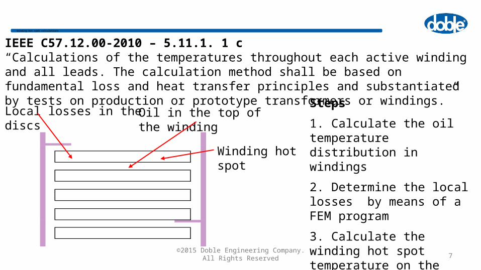
W inding hot spot calculations
Winding hot spot
Oil in the top of the windingLocal losses in the discsSteps
1. Calculate the oil temperature distribution in windings
2. Determine the local losses by means of a FEM program
3. Calculate the winding hot spot temperature on the basis of the local losses and the oil temperature in the winding
IEEE C57.12.00-2010 – 5.11.1. 1 c“Calculations of the temperatures throughout each active winding and all leads. The calculation method shall be based on fundamental loss and heat transfer principles and substantiated by tests on production or prototype transformers or windings.”

©2015 Doble Engineering Company. All Rights Reserved 8
W inding cooling
Heat transfer by conduction from conductor to conductor, from conductor to insulation
Example of a multi-strand conductor (CTC)
paper insulation
strand insulation – enamel and epoxy
Thermal conductivity W/m*K- Copper ~380- Aluminum ~220- Paper; pressboard oil-treated ~0.17-0.25
CTC without paper insulation

©2015 Doble Engineering Company. All Rights Reserved 9
O il flow in w indings - convection
Guided oil flowNon guided oil flow
Oil flow is blocked and heat transfer is limited by spacers, sticks and other insulating elements which are required by dielectric and mechanical design
Washer (guides) controlling oil
Heat transfer is dependent on the flow properties such as velocity, oil viscosity, vertical or horizontal cooling surface

©2015 Doble Engineering Company. All Rights Reserved 10
Losses and C ooling - Transform er m odel law
CuFem SJSBtfIEPowerRatedTransfomer ******44.4*~ S2 [MVA]
S1[MVA]
Assuming the same use of the active materials (current density, core flux density) we can derive the following relation for transformers with rated power S1 and S2
0.5
S1PowerRated
S2PowerRated
A1SurfaceCooling
A2SurfaceCooling
0.75
S1PowerRated
S2PowerRated
L1LossesTrafo
L2LossesTrafo
Losses increase faster with a change in the rated power than the winding effective cooling surface

©2015 Doble Engineering Company. All Rights Reserved 11
Losses and C ooling
• More oil flow required to dissipate the heat from the core and windings; larger external cooling system
• Pumps and fans may be required for larger transformers
ONAN
OFAF
ODAF
Total losses for a very large unit can be in excess of 2000 kW (2 MW!)
Very low losses comparing to the available cooling surface

©2015 Doble Engineering Company. All Rights Reserved 12
• Heat run test• Overload test• Extended Over excitation
Special testing- Fiber optics can be used to measure winding hot spot rise and top
oil temperatures in the windings.- Thermocouples can be installed to measure stray loss heating. - Thermovision scanning can be done to verify tank wall heating
especially for a generator step-up transformer.
Together with the gas analysis this would validate the calculated temperature rises and confirm the transformer can readily accept the required base load and overload
Testing
Fibre optics installed in a winding
Example of a thermovision results

©2015 Doble Engineering Company. All Rights Reserved 13
• The cooling design together with dielectric and short circuit consideration is critical for transformer performance in service
• Winding hot spot is a dimensioning factor; increase of ~ 6-8 deg. due to a cooling system failure, material problems, design or production mistakes will reduce transformer life by a factor of ~ 2
• Cooling system selection and design should be optimized for expected service conditions (ambient, loading, footprint) and validated during the factory acceptance tests
• Load and temperature monitoring (possibly with a direct measurement by fiber optics) gives users a possibility to precisely track the loss of life
Transform er C ooling B asics - S um m ary

©2015 Doble Engineering Company. All Rights Reserved 14
Life of a Transformer™ SeminarFebruary 9 - 13, 2015 | San Antonio, Texas USA
Transformer Cooling Basics
Vasanth Vailoor & Kevin RileyTrantech Radiator Products, Inc.

©2015 Doble Engineering Company. All Rights Reserved 15
Types of Transformer Cooling Systems
• ONAN – Oil Natural Air Natural• ONAF – Oil Natural Air Forced• OFAF – Oil Forced Air Forced• OFWF – Oil Forced Water Forced• OD Applications - are always forced oil flow that is
directed through predetermined paths in the transformer winding.

©2015 Doble Engineering Company. All Rights Reserved 16
ONAN - Transformer Cooling Systems
• ONAN – Formerly known as OA.• Natural convection flow of hot oil is
utilized to dissipate heat.• Radiator or tube applications are
predominately used.• Least expensive form of cooling if
application and cooling levels are met.

©2015 Doble Engineering Company. All Rights Reserved 17
Pros
• No Pumps or Fans• Long Life Expectancy• Very Low Maintenance• Available in various coatings• Ability to add pumps or fans for
additional cooling capacity• Low Noise
Cons
• Consumes more space than some other applications.
• Requires the most connection points to transformer.
ONAN - Transformer Cooling Systems

©2015 Doble Engineering Company. All Rights Reserved 18
ONAF - Transformer Cooling Systems
• ONAF – Formerly known as FA.• Natural convection flow of hot oil is
utilized in conjunction with cooling fans.
• Heat dissipation is increased across cooling surfaces by air movement.
• Most common application in the field.
• Offers dual ratings as an ONAN/ONAF system.

©2015 Doble Engineering Company. All Rights Reserved 19
Pros
• No Pumps needed• Long Life Expectancy• Low maintenance on radiators
while fans are considered consumables.
• Can be dual rated as heat transfer application depending on fans being used or turned off.
Cons
• Reduced capacity if auxiliary power is lost.
• Fans require maintenance and replacement during transformers life.
• Noise levels increased as compared to ONAN applications.
ONAF - Transformer Cooling Systems

©2015 Doble Engineering Company. All Rights Reserved 20
OFAF - Transformer Cooling Systems
• OFAF – Formally known as FOA.• Heat dissipation is increased
across cooling surfaces by air movement while oil is circulated with pumps.
• Can cool higher load levels than ONAN or ONAF applications.
• Higher heat dissipation within a smaller space / footprint.

©2015 Doble Engineering Company. All Rights Reserved 21
OFAF with Radiators
• Fans and pumps work to cool radiators plates as needed.
• Can be set-up as multiple stage cooling system.
• Can be used as ONAN system at lower temperatures.
• Most flexible means of cooling transformers rated at 30 MVA or higher.
OFAF - Transformer Cooling Systems
Fans
Pumps

©2015 Doble Engineering Company. All Rights Reserved 22
Pros
• System Flexibility• Long Life Expectancy with
preventative maintenance.• Easier maintenance and cleaning
of cooling surfaces.• Energy consumption of system
can be optimized compared to other forced oil applications.
Cons
• Auxillary power required.• Fans and pumps need monitoring
and maintenance.• Potential issues in certain
environments as with any forced air application.
OFAF with Radiators

©2015 Doble Engineering Company. All Rights Reserved 23
OFAF with Coolers
• Variety of cooling surfaces and fin styles to meet applications.
• Requires fans and pumps operating to achieve cooling demand.
• Less connections to tank than other applications.
• Proven technology.
OFAF - Transformer Cooling Systems

©2015 Doble Engineering Company. All Rights Reserved 24
Pros
• High cooling capacities.• Less space than ONAN / OFAF
with radiator applications.• Lower Top Oil Temperature in
general use.
Cons• Consumes more energy and higher
noise levels.• Fans and pumps require maintenance
and replacement during transformers life.
• Potential issues in certain environments as with any forced air application.
• No cooling capacity with loss of auxiliary power.
OFAF with Coolers

©2015 Doble Engineering Company. All Rights Reserved 25
• Most cooling capacity. • Oil is cooled by forced water
application.• Least amount of connections
to tank.• Requires water source unless
a closed looped system is used.
• Small and compact but higher maintenance.
OFWF - Transformer Cooling Systems

©2015 Doble Engineering Company. All Rights Reserved 26
Pros
• Highest potential cooling capacities of all applications.
• Least amount of space.• Method of cooling has been used
for many years.• Maintenance personnel are
generally familiar with technology.• Little or no extra noise.
Cons
• Oil and water pumps can fail.• Possibilities of oil contamination
by water upon failure.• Tubes foul and must be cleaned.• Water source is needed in most
high heat applications.• Bacteria hazards if water system
is not a closed loop system.
OFWF – Transformer Cooling Systems

©2015 Doble Engineering Company. All Rights Reserved 27
• Existing cooling systems can be adversely effected by new construction of ballistic barriers and protective structures.
• New transformer cooling system designs must take into consideration these potential air flow obstructions.
• Indoor and underground applications are becoming more common.

©2015 Doble Engineering Company. All Rights Reserved 28
• Firewall installations or relocation of transformers can lead to a need for cooling systems redesign or enhancement.
• Lack of auxiliary power or water requirements when relocating transformers may drive a need for cooling system changes.
• Noise and seismic requirements can be factors either by equipment relocation or regulatory changes.

©2015 Doble Engineering Company. All Rights Reserved 29
Cooling System Maintenance (Past)
• Cooling systems historically have seen little or no maintenance until failures occur.
• Generally visual inspections detect issues.• With deregulation more transformers are running at higher loads with no
upgrades to cooling capacities or systems.• Sometimes cooling systems are replaced to original specifications when
cooling upgrades are actually needed.• Environmental and regulatory constraints sometimes overlooked during
maintenance or transformer relocation.

©2015 Doble Engineering Company. All Rights Reserved 30
Cooling System Maintenance (Present)
• Cooling systems designed for OEM and replacement applications should be viewed as part of the essential component life of the overall transformer.
• Preventative and predictive maintenance applications are essential.• Lean methodologies used in the manufacturing industry are being
implemented throughout the utility industry. Example: TPM (Total Productive Maintenance).
• Proper cooling surface protection and maintenance can extend the life of your cooling system up to 30%.
• Asking the cooling industry experts about what the best system for your application is instead of repeating old specifications is a must.
©2015 Doble Engineering Company. All Rights Reserved 31
Cooling System ‘Musts’:
• At a minimum, complete semi-annual inspections of external surfaces for corrosion protection. This includes valves, radiators, piping, sheet metal surfaces, tubes, pumps and any other surface. Just because it is galvanized or stainless does not always make it less susceptible to damage from certain elements.
• Complete periodic maintenance on all moving components within the system. Vibration, thermal scans and sound are still the best ways but you must document and compare.
• Clean cooling surfaces of build-up, debris and fouling.• Remember that cleaning is inspection!

©2015 Doble Engineering Company. All Rights Reserved 32
Cooling System ‘Musts Not's’:
• Spraying water over the transformer or cooling system as a means to reduce temperatures for extended periods.
• Using any forced air application in caustic, sea water or chemical environments without the proper base material and coatings. Ask the heat exchanger supplier for recommendations of materials.
• Not documenting maintenance inspections and findings.• Attempting repairs to existing cooling equipment components without proper
materials or knowledge of procedures.• Allowing leaks in the system to continue without remediation.• Remember that all transformer components deteriorate and fail. Limited or No
periodic maintenance to the cooling system accelerates system failures.

©2015 Doble Engineering Company. All Rights Reserved 33
Factors affecting Heat Transfer
• Width (9”, 12”, 15”, 520mm)
• Length (Custom – up to 15 feet)
• # of Plates
• Hydraulic Diameter
• Oil Flow Rate (ON or OF)
• Air Flow Rate (AN or AF)
• Plate Spacing (1.77”, 2”, 2 ¼”)
•Surrounding environment / constraints
How does it influence cost-economics?

©2015 Doble Engineering Company. All Rights Reserved 34
Case Study – I 90 MVA GSU

©2015 Doble Engineering Company. All Rights Reserved 35
Case Study – I (cont’d)Rusty water cooler removed from transformer

©2015 Doble Engineering Company. All Rights Reserved 36
Case Study – I (cont’d)Radiator bank designed with fans

©2015 Doble Engineering Company. All Rights Reserved 37
Case Study – I (cont’d)

©2015 Doble Engineering Company. All Rights Reserved 38
C ase S tu d y – I (co n t’d )
0
5
10
15
20
25
30
35
40
8/2/06 8/4/06 8/6/06 8/8/06 8/10/06
Hourly readings
T,
Win
din
g H
ot
Sp
ot
min
us
A
mb
ien
t [°
C]
10
15
20
25
30
35
40
2/2/06 2/4/06 2/6/06 2/8/06 2/10/06
Hourly readings
T, W
ind
ing
Ho
t S
po
t m
inu
s
Am
bie
nt
[°
C]

©2015 Doble Engineering Company. All Rights Reserved 39
C ase S tu d y – II
Copper Mine – Salt Lake City – 1958 – 90MVA

©2015 Doble Engineering Company. All Rights Reserved 40
C ase S tu d y – II

©2015 Doble Engineering Company. All Rights Reserved 41
C ase S tu d y – III (Id en tificatio n )

©2015 Doble Engineering Company. All Rights Reserved 42
C ase S tu d y – III (P ro p o sal)

©2015 Doble Engineering Company. All Rights Reserved 43
C ase S tu d y – III (F ield Testin g )

©2015 Doble Engineering Company. All Rights Reserved 44
C ase S tu d y – III (C o m p letio n )

©2015 Doble Engineering Company. All Rights Reserved 45
C ase S tu d y – Tu b e R ep lacem en t

©2015 Doble Engineering Company. All Rights Reserved 46
C ase S tu d y – Tu b e R ep lacem en t

©2015 Doble Engineering Company. All Rights Reserved 47
Cooler Design and Selection
• Selection and Matching
- Air or Water flow capacity
- Oil flow requirement
- Operating Conditions

©2015 Doble Engineering Company. All Rights Reserved 48
Cooler Design and Selection (cont’d)

©2015 Doble Engineering Company. All Rights Reserved 49
• Before
Case Study – Cooler Replacement
Leaking coolers and pumps. Unit losing up to 30 gallons per week. Cost of waste oil remediation, replacement oil and labor had become a daily issue.
©2015 Doble Engineering Company. All Rights Reserved 50
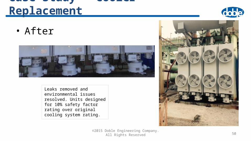
• After
Case Study – Cooler Replacement
Leaks removed and environmental issues resolved. Units designed for 10% safety factor rating over original cooling system rating.

©2015 Doble Engineering Company. All Rights Reserved 51
Conclusions
• Simple design process using heat transfer analysis but can
get complex especially for Forced Convection Systems.
• Optimization must focus on entire Transformer Cooling
System – not in parts.
• Periodic maintenance is critical to the overall cooling system.
• The cooling system is not an independent system.