Transformer Protection Relays (Buchholz Principle)...Transformer Protection Relays (Buchholz...
48
Transformer Protection Relays (Buchholz Principle) Elektromotoren und Gerätebau Barleben GmbH
Transcript of Transformer Protection Relays (Buchholz Principle)...Transformer Protection Relays (Buchholz...
Transformer Protection Relays(Buchholz Principle)
Elektromotoren undGerätebau Barleben GmbH
2
Elektromotoren und Gerätebau Barleben GmbH
Table of contentsPage
Company history 4
1 Preface 5
2 Design features 6
3 Function 8
3.1 Gas accumulation 8
3.2 Insulating liquid loss 9
3.3 Insulating liquid flow 9
4 Tests 10
5 Type list of single-float Buchholz relays 11
5.1 Single-float Buchholz relays with threaded connection 11
5.2 Single-float Buchholz relays with flanged connection 11
5.3 Single-float Buchholz relays with flat flanged connection 12
6 Switching system design options for single-float Buchholz relays 13
7 Type list of double-float Buchholz relays 14
7.1 Double-float Buchholz relays with threaded connection 14
7.2 Double-float Buchholz relays with flanged connection (round) 15
7.3 Double-float Buchholz relays with flat flanged connection (round) 17
7.4 Double-float Buchholz relays with flanged connection (square) 18
7.5 Double-float Buchholz relays with geometrical flange dimensions according to Chinese norm 18
7.6 Double-float Buchholz relays with geometrical flange dimensions according to former French norm 19
7.7 Double-float Buchholz relays with geometrical flange dimensions according to former British standard 20
8 Switching system design options for double-float Buchholz relays 21
9 Technical data 26
3
10 Options/Special designs 27
10.1 Explanations to code 17 A 29
10.2 Explanations to codes 23 and 24/24B 29
10.3 Explanations to code 32 30
11 SMART-Buchholz relay 31
11.1 Explanations to code 60 - Gas volume sensor - NM series 32
11.1.1 Construction of Buchholz relay with gas volume sensor 32
11.1.2 Additional function of Buchholz relay with gas volume sensor 32
11.1.3 Analog measuring device - analog gas volume measurement 33
11.2 Explanations to code 61 - Buchholz relay with temperature sensor 34
11.2.1 Construction of Buchholz relay with temperature sensor 34
11.2.2 Additional function of Buchholz relay with temperature sensor 34
11.3 Explanations to code 62 - Buchholz relay with moisture-temperature sensor 35
11.3.1 Construction of the Buchholz relay with moisture-temperature sensor 35
11.3.2 Additional function of the Buchholz relay with moisture-temperature sensor 35
12 Ordering data/Type code 36
12.1 Single-float Buchholz relays 36
12.2 Double-float Buchholz relays 37
12.3 Ordering example 38
13 Additional devices for Buchholz relays 39
13.1 Gas sampling device ZG 1.2. 39
13.2 Other additional devices for Buchholz relays 43
14 Other protection devices 45
15 Breathing Buffer Box 47
4
Elektromotoren und Gerätebau Barleben GmbH
Company historySince its foundation the company has passed through an eventful history with regard to ownership, affiliation and change of name associated with such development.
1863 Foundation of the company as sugar factory
1921 Development of Buchholz relay by Max Buchholz
1943 Branch of SIEMENS Magdeburg
1948 VEB Elektromotorenwerk Barleben; VEM (state-owned firm)
1951 VEB Starkstromanlagenbau Magdeburg (state-owned firm)
1951 Start of manufacture of Buchholz relays in Barleben
1965 Start of manufacture of monitoring relays for tap changers in Barleben
1970 VEB Elektrotechnik und Gerätebau Magdeburg; EGEM (state-owned firm)
1980 VEB Kombinat Elektromaschinenbau Dresden VEB Elektromotorenwerk Barleben; VEM; ELMO (state-owned firm)
1990 VEM Antriebstechnik AG Dresden Elektromotorenwerk Barleben GmbH; VEM; ELMO (public limited company)
1993 Elektromotoren und Gerätebau Barleben GmbH; EMB (privately owned company)
2005 Start of manufacture of Buchholz relays NM series
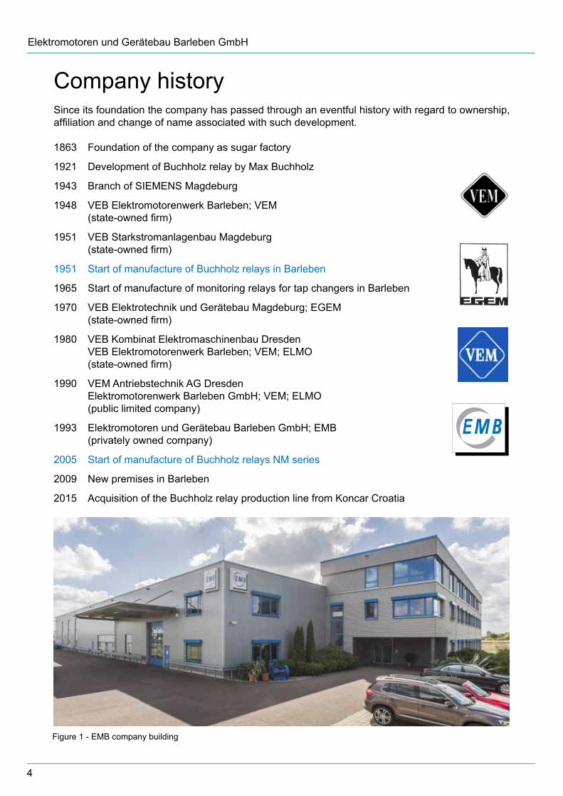
2009 New premises in Barleben
2015 Acquisition of the Buchholz relay production line from Koncar Croatia
Figure 1 - EMB company building
5
1 Preface
More than 1.5 million relays
have been sold worldwide in 60 years!
The Buchholz relay was developed in 1921 by Max Buchholz, Oberrat (senior councillor) at Preußische Elektrizitäts-A.G. (Prussian electricity company) in Kassel. Since that time it has been an important protection and monitoring device for insulating liquid filled transformers with conservator and choke coils. It also allows separate monitoring of oil-filled bushings or cable terminal boxes. It is mounted in the cooling cycle of the device to be protected and responds to faults such as gas generation, loss of as well as high flow rates of the insulating liquid.
For transformers with hermetical closure by means of a hydro-type compensator (rubber sack) in the conservator, the Buchholz relay can be used also a monitoring device (air cell failure relay) of the hydro-type compensator.
The Buchholz relay is suitable for open-air as well as indoor installations.
The type diversity of the Buchholz relay is tailored to norms and standards as well as to special customer demands. The type of relay to be used depends on the nominal rating and construction features of the device to be protected. Our range of products permits optimum adaptation to actual requirements.
Elektromotoren und Gerätebau GmbH (EMB GmbH) provides more than 60 years experience in producing Buchholz relays and other protective devices for liquid-cooled and liquid-insulated devices. It ranks today among the most distinguished manufacturers of this type of equipment.
EMB Buchholz relays are in compliance with EN 50216-2 and are known for their easy operation, high reliability and extremely long life.
Our staff of highly qualified engineers and experienced skilled workers do their best to guarantee top-quality high-precision products. The casings are machined on modern CNC-controlled machines. All products are subjected to final inspection when all functions are checked using special test equipment.
Profound experience and expertise in this special area are a sound basis for high product quality. Extensive references from reputed transformer manufacturers as well as other users are proof of the high qualitative level of the products.
EMB has been certified according to: DIN EN ISO 9001:2015, AEO F, Known Consignor (Airfreight Security) and EAC. Further certifications have been awarded by well-known independent test laboratories such as TÜV Rheinland and TZO.
Figure 2 - Certificates
6
Elektromotoren und Gerätebau Barleben GmbH
2 Design features
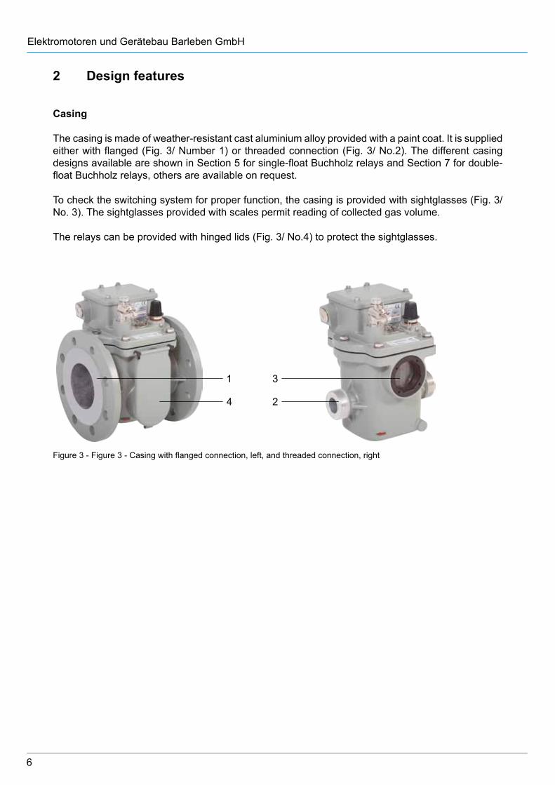
Casing
The casing is made of weather-resistant cast aluminium alloy provided with a paint coat. It is supplied either with flanged (Fig. 3/ Number 1) or threaded connection (Fig. 3/ No.2). The different casing designs available are shown in Section 5 for single-float Buchholz relays and Section 7 for double-float Buchholz relays, others are available on request.
To check the switching system for proper function, the casing is provided with sightglasses (Fig. 3/ No. 3). The sightglasses provided with scales permit reading of collected gas volume.
The relays can be provided with hinged lids (Fig. 3/ No.4) to protect the sightglasses.
Figure 3 - Figure 3 - Casing with flanged connection, left, and threaded connection, right
1
4
3
2
7
Cover
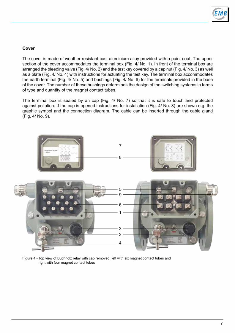
The cover is made of weather-resistant cast aluminium alloy provided with a paint coat. The upper section of the cover accommodates the terminal box (Fig. 4/ No. 1). In front of the terminal box are arranged the bleeding valve (Fig. 4/ No. 2) and the test key covered by a cap nut (Fig. 4/ No. 3) as well as a plate (Fig. 4/ No. 4) with instructions for actuating the test key. The terminal box accommodates the earth terminal (Fig. 4/ No. 5) and bushings (Fig. 4/ No. 6) for the terminals provided in the base of the cover. The number of these bushings determines the design of the switching systems in terms of type and quantity of the magnet contact tubes.
The terminal box is sealed by an cap (Fig. 4/ No. 7) so that it is safe to touch and protected against pollution. If the cap is opened instructions for installation (Fig. 4/ No. 8) are shown e.g. the graphic symbol and the connection diagram. The cable can be inserted through the cable gland (Fig. 4/ No. 9).
Figure 4 - Top view of Buchholz relay with cap removed, left with six magnet contact tubes and right with four magnet contact tubes
7
8
6
95
1
23
4
8
Elektromotoren und Gerätebau Barleben GmbH
3 Function
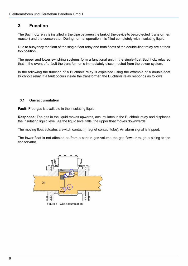
The Buchholz relay is installed in the pipe between the tank of the device to be protected (transformer, reactor) and the conservator. During normal operation it is filled completely with insulating liquid.
Due to buoyancy the float of the single-float relay and both floats of the double-float relay are at their top position.
The upper and lower switching systems form a functional unit in the single-float Buchholz relay so that in the event of a fault the transformer is immediately disconnected from the power system.
In the following the function of a Buchholz relay is explained using the example of a double-float Buchholz relay. If a fault occurs inside the transformer, the Buchholz relay responds as follows:
3.1 Gas accumulation
Fault: Free gas is available in the insulating liquid.
Response: The gas in the liquid moves upwards, accumulates in the Buchholz relay and displaces the insulating liquid level. As the liquid level falls, the upper float moves downwards.
The moving float actuates a switch contact (magnet contact tube). An alarm signal is tripped.
The lower float is not affected as from a certain gas volume the gas flows through a piping to the conservator.
Gas
Öl
Figure 5 - Gas accumulation
Oil
Gas
9
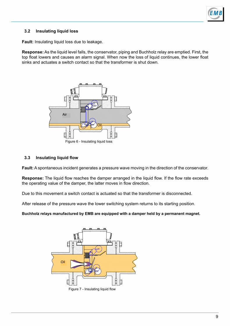
3.3 Insulating liquid flow
Fault: A spontaneous incident generates a pressure wave moving in the direction of the conservator.
Response: The liquid flow reaches the damper arranged in the liquid flow. If the flow rate exceeds the operating value of the damper, the latter moves in flow direction.
Due to this movement a switch contact is actuated so that the transformer is disconnected.
After release of the pressure wave the lower switching system returns to its starting position.
Buchholz relays manufactured by EMB are equipped with a damper held by a permanent magnet.
3.2 Insulating liquid loss
Fault: Insulating liquid loss due to leakage.
Response: As the liquid level falls, the conservator, piping and Buchholz relay are emptied. First, the top float lowers and causes an alarm signal. When now the loss of liquid continues, the lower float sinks and actuates a switch contact so that the transformer is shut down.
Luft
Öl
Figure 6 - Insulating liquid loss
Oil
Öl
Figure 7 - Insulating liquid flow
Oil
Air
10
Elektromotoren und Gerätebau Barleben GmbH
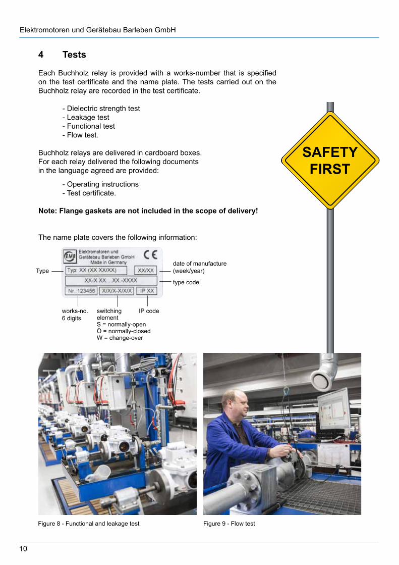
4 Tests
Each Buchholz relay is provided with a works-number that is specified on the test certificate and the name plate. The tests carried out on the Buchholz relay are recorded in the test certificate.
- Dielectric strength test - Leakage test - Functional test - Flow test.
Buchholz relays are delivered in cardboard boxes. For each relay delivered the following documents in the language agreed are provided:
- Operating instructions - Test certificate.
Note: Flange gaskets are not included in the scope of delivery!
The name plate covers the following information:
Figure 9 - Flow testFigure 8 - Functional and leakage test
works-no.6 digits
switchingelementS = normally-openÖ = normally-closedW = change-over
IP code
type code
date of manufacture(week/year)Type
11
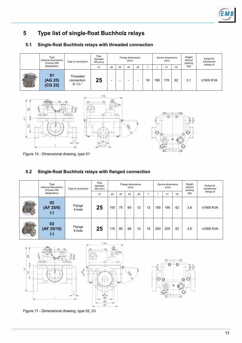
5 Type list of single-float Buchholz relays
5.1 Single-float Buchholz relays with threaded connection
Type(Internal description)
(Former DIN designation)
Type of connection
Pipe diameterDN (mm)
Flange dimensions(mm)
Device dimensions(mm)
Weight without packing
(kg)
Suited fortransformerratings of
d1 d2 d3 d4 d5 f l h1 h2
01(AG 25)(CG 25)
Threadedconnection
G 1½ “25 - - - - 16 185 170 62 3,1 ≤1600 KVA
Figure 10 - Dimensional drawing, type 01
Type(Internal description)
(Former DIN designation)
Type of connection
Pipe diameterDN (mm)
Flange dimensions(mm)
Device dimensions(mm)
Weight without packing
(kg)
Suited fortransformerratings of
d1 d2 d3 d4 d5 f l h1 h2
02(AF 25/6)
(-)
Flange4-hole 25 100 75 60 12 12 185 195 62 3,6 ≤1600 KVA
03(AF 25/10)
(-)
Flange4-hole 25 115 85 68 14 16 200 205 62 4,0 ≤1600 KVA
5.2 Single-float Buchholz relays with flanged connection
Figure 11 - Dimensional drawing, type 02, 03
12
Elektromotoren und Gerätebau Barleben GmbH
Type(Internal description)
(former DIN designation)
Type of connection
Pipe diameterDN (mm)
Flange dimensions(mm)
Device dimensions(mm)
Weight without packing
(kg)
Suited fortransformerratings of
d1 d2 d3 d4 d5 f l h1 h2
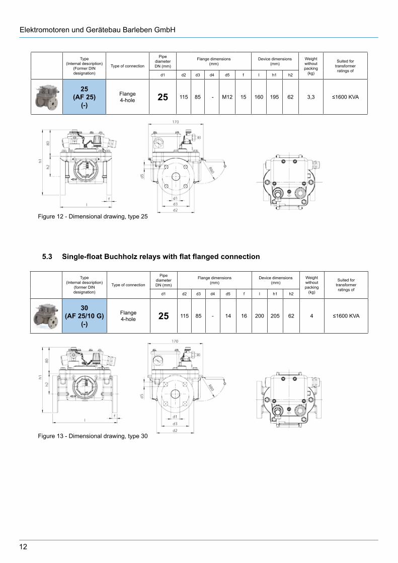
30(AF 25/10 G)
(-)
Flange4-hole 25 115 85 - 14 16 200 205 62 4 ≤1600 KVA
Figure 13 - Dimensional drawing, type 30
5.3 Single-float Buchholz relays with flat flanged connection
Figure 12 - Dimensional drawing, type 25
Type(Internal description)
(Former DIN designation)
Type of connection
Pipe diameterDN (mm)
Flange dimensions(mm)
Device dimensions(mm)
Weight without packing
(kg)
Suited fortransformerratings of
d1 d2 d3 d4 d5 f l h1 h2
25(AF 25)
(-)
Flange4-hole 25 115 85 - M12 15 160 195 62 3,3 ≤1600 KVA
13
...1 ...2 ...3 ...4 ...5 ...6
1 NO 1 NC 2 NO 2 NC 1 NO and 1 NC 1 CO
13
14
11
12
13
14 24
23 11
12 22
21 13
14 12
11
4
1
2
...7 ...8 ...92 CO 1 NO and 1 CO 3 NO
24
21
22 12
11
14 14
11
1224
23
33
23
34
14 2413
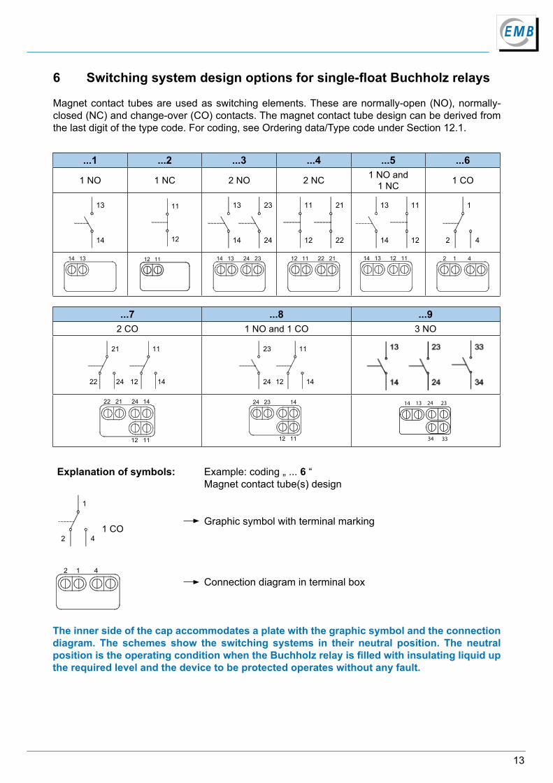
6 Switching system design options for single-float Buchholz relays
Magnet contact tubes are used as switching elements. These are normally-open (NO), normally-closed (NC) and change-over (CO) contacts. The magnet contact tube design can be derived from the last digit of the type code. For coding, see Ordering data/Type code under Section 12.1.
Explanation of symbols: Example: coding „ ... 6 “Magnet contact tube(s) design
4
1
2 1 CO
Graphic symbol with terminal marking
Connection diagram in terminal box
The inner side of the cap accommodates a plate with the graphic symbol and the connection diagram. The schemes show the switching systems in their neutral position. The neutral position is the operating condition when the Buchholz relay is filled with insulating liquid up the required level and the device to be protected operates without any fault.
14
Elektromotoren und Gerätebau Barleben GmbH
Type(Internal description)
(Former DIN designation)
Type of connection
Pipe diameterDN (mm)
Flange dimensions(mm)
Device dimensions(mm)
Weight without packing
(kg)
Suited fortransformerratings of
d1 d2 d3 d4 d5 f l h1 h2
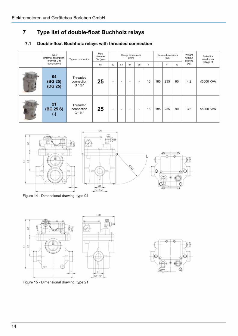
04(BG 25)(DG 25)
Threaded connection
G 1½ “25 - - - - 16 185 235 90 4,2 ≤5000 KVA
21(BG 25 S)
(-)
Threaded connection
G 1½ “25 - - - - 16 185 235 90 3,6 ≤5000 KVA
Figure 14 - Dimensional drawing, type 04
Figure 15 - Dimensional drawing, type 21
7 Type list of double-float Buchholz relays
7.1 Double-float Buchholz relays with threaded connection
15
Type(Internal description)
(Former DIN designation)
Type of connection
Pipe diameterDN (mm)
Flange dimensions(mm)
Device dimensions(mm)
Weight without packing
(kg)
Suited fortransformerratings of
d1 d2 d3 d4 d5 f l h1 h2
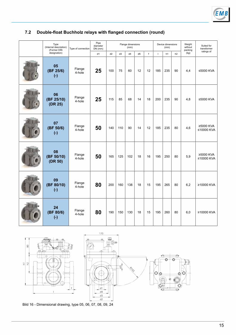
05(BF 25/6)
(-)
Flange4-hole 25 100 75 60 12 12 185 235 90 4,4 ≤5000 KVA
06(BF 25/10)
(DR 25)
Flange4-hole 25 115 85 68 14 18 200 235 90 4,8 ≤5000 KVA
07(BF 50/6)
(-)
Flange4-hole 50 140 110 90 14 12 185 235 80 4,6 ≥5000 KVA
≤10000 KVA
08(BF 50/10)
(DR 50)
Flange4-hole 50 165 125 102 18 16 195 250 80 5,9 ≥5000 KVA
≤10000 KVA
09(BF 80/10)
(-)
Flange4-hole 80 200 160 138 18 15 195 265 80 6,2 ≥10000 KVA
24(BF 80/6)
(-)
Flange4-hole 80 190 150 130 18 15 195 260 80 6,0 ≥10000 KVA
7.2 Double-float Buchholz relays with flanged connection (round)
Bild 16 - Dimensional drawing, type 05, 06, 07, 08, 09, 24
16
Elektromotoren und Gerätebau Barleben GmbH
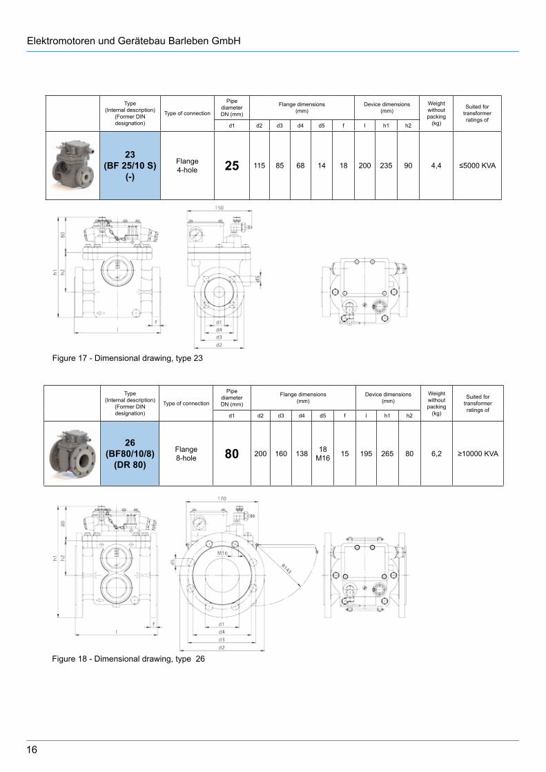
Figure 17 - Dimensional drawing, type 23
Figure 18 - Dimensional drawing, type 26
Type(Internal description)
(Former DIN designation)
Type of connection
Pipe diameterDN (mm)
Flange dimensions(mm)
Device dimensions(mm)
Weight without packing
(kg)
Suited fortransformerratings of
d1 d2 d3 d4 d5 f l h1 h2
23(BF 25/10 S)
(-)
Flange4-hole 25 115 85 68 14 18 200 235 90 4,4 ≤5000 KVA
Type(Internal description)
(Former DIN designation)
Type of connection
Pipe diameterDN (mm)
Flange dimensions(mm)
Device dimensions(mm)
Weight without packing
(kg)
Suited fortransformerratings of
d1 d2 d3 d4 d5 f l h1 h2
26(BF80/10/8)
(DR 80)
Flange8-hole 80 200 160 138 18
M16 15 195 265 80 6,2 ≥10000 KVA
17
Figure 20 - Dimensional drawing, type 28, 31
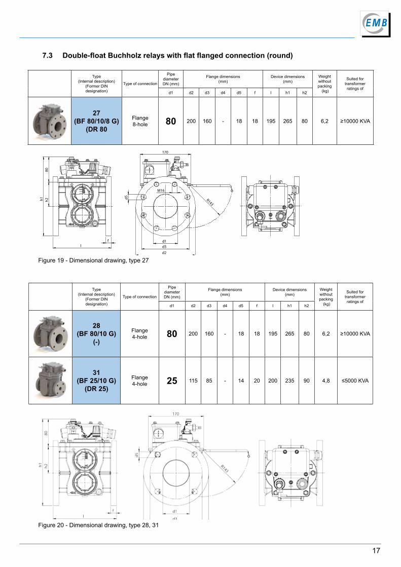
7.3 Double-float Buchholz relays with flat flanged connection (round)
Type(Internal description)
(Former DIN designation)
Type of connection
Pipe diameterDN (mm)
Flange dimensions(mm)
Device dimensions(mm)
Weight without packing
(kg)
Suited fortransformerratings of
d1 d2 d3 d4 d5 f l h1 h2
28(BF 80/10 G)
(-)
Flange4-hole 80 200 160 - 18 18 195 265 80 6,2 ≥10000 KVA
31(BF 25/10 G)
(DR 25)
Flange4-hole 25 115 85 - 14 20 200 235 90 4,8 ≤5000 KVA
Type(Internal description)
(Former DINdesignation)
Type of connection
Pipe diameterDN (mm)
Flange dimensions(mm)
Device dimensions(mm)
Weight without packing
(kg)
Suited fortransformerratings of
d1 d2 d3 d4 d5 f l h1 h2
27(BF 80/10/8 G)
(DR 80
Flange8-hole 80 200 160 - 18 18 195 265 80 6,2 ≥10000 KVA
Figure 19 - Dimensional drawing, type 27
80
h2 h1
l f d1
d3
d2
170
d5
M16
R143
18
Elektromotoren und Gerätebau Barleben GmbH
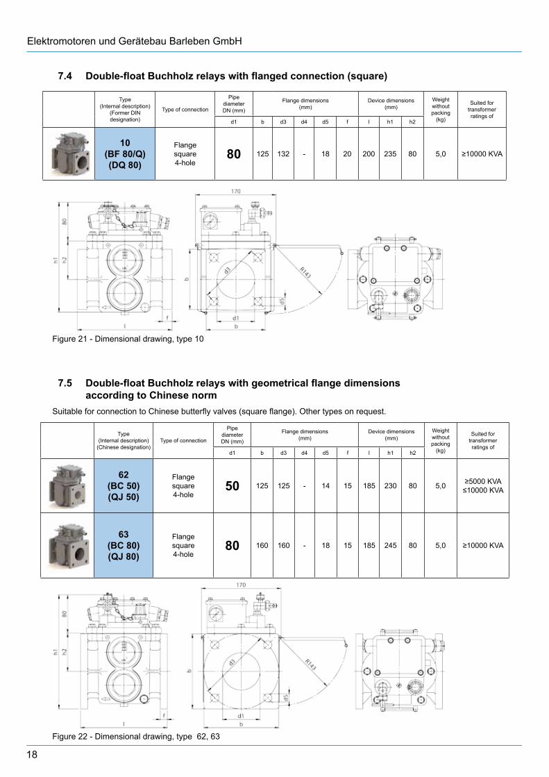
Type(Internal description)
(Former DIN designation)
Type of connection
Pipe diameterDN (mm)
Flange dimensions(mm)
Device dimensions(mm)
Weight without packing
(kg)
Suited fortransformerratings of
d1 b d3 d4 d5 f l h1 h2
10(BF 80/Q)(DQ 80)
Flangesquare4-hole
80 125 132 - 18 20 200 235 80 5,0 ≥10000 KVA
Type(Internal description)
(Chinese designation)Type of connection
Pipe diameterDN (mm)
Flange dimensions(mm)
Device dimensions(mm)
Weight without packing
(kg)
Suited fortransformerratings of
d1 b d3 d4 d5 f l h1 h2
62(BC 50)(QJ 50)
Flangesquare4-hole
50 125 125 - 14 15 185 230 80 5,0 ≥5000 KVA≤10000 KVA
63(BC 80)(QJ 80)
Flangesquare4-hole
80 160 160 - 18 15 185 245 80 5,0 ≥10000 KVA
Figure 21 - Dimensional drawing, type 10
7.4 Double-float Buchholz relays with flanged connection (square)
7.5 Double-float Buchholz relays with geometrical flange dimensions according to Chinese norm Suitable for connection to Chinese butterfly valves (square flange). Other types on request.
Figure 22 - Dimensional drawing, type 62, 63
19
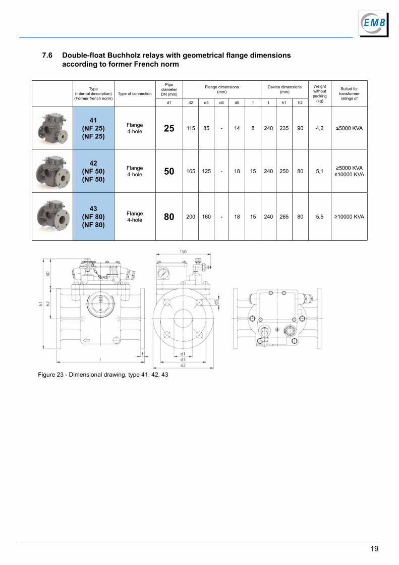
Type(Internal description)(Former french norm)
Type of connection
Pipe diameterDN (mm)
Flange dimensions(mm)
Device dimensions(mm)
Weight without packing
(kg)
Suited fortransformerratings of
d1 d2 d3 d4 d5 f l h1 h2
41(NF 25)(NF 25)
Flange4-hole 25 115 85 - 14 8 240 235 90 4,2 ≤5000 KVA
42(NF 50)(NF 50)
Flange4-hole 50 165 125 - 18 15 240 250 80 5,1 ≥5000 KVA
≤10000 KVA
43(NF 80)(NF 80)
Flange4-hole 80 200 160 - 18 15 240 265 80 5,5 ≥10000 KVA
7.6 Double-float Buchholz relays with geometrical flange dimensions according to former French norm
Figure 23 - Dimensional drawing, type 41, 42, 43
20
Elektromotoren und Gerätebau Barleben GmbH
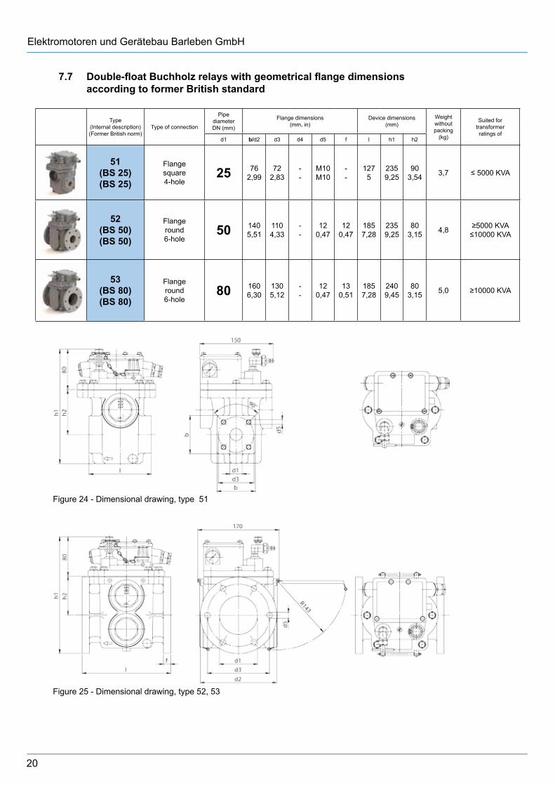
Type(Internal description)(Former British norm)
Type of connection
Pipe diameterDN (mm)
Flange dimensions(mm, in)
Device dimensions(mm)
Weight without packing
(kg)
Suited fortransformerratings of
d1 b/d2 d3 d4 d5 f l h1 h2
51(BS 25)(BS 25)
Flangesquare4-hole
25 762,99
722,83
--
M10M10
--
1275
2359,25
903,54 3,7 ≤ 5000 KVA
52(BS 50)(BS 50)
Flangeround6-hole
50 1405,51
1104,33
--
120,47
120,47
1857,28
2359,25
803,15 4,8 ≥5000 KVA
≤10000 KVA
53(BS 80)(BS 80)
Flangeround6-hole
80 1606,30
1305,12
--
120,47
130,51
1857,28
2409,45
803,15 5,0 ≥10000 KVA
Figure 24 - Dimensional drawing, type 51
Figure 25 - Dimensional drawing, type 52, 53
7.7 Double-float Buchholz relays with geometrical flange dimensions according to former British standard

21
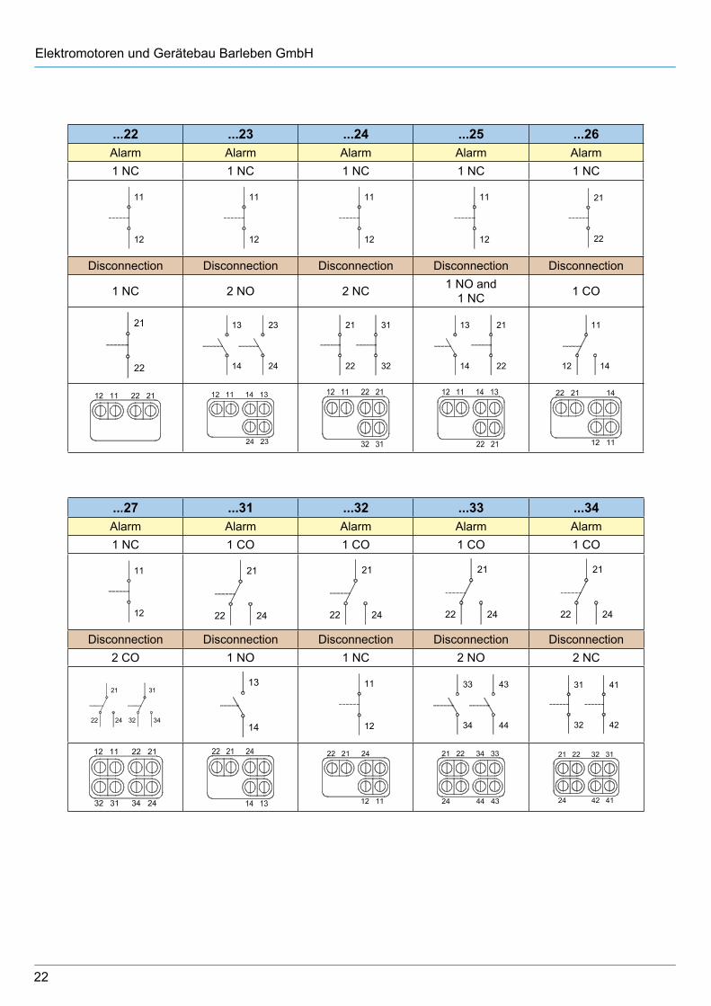
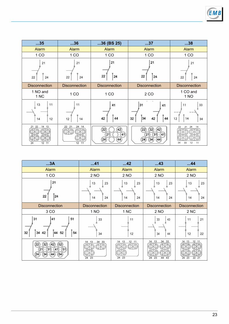
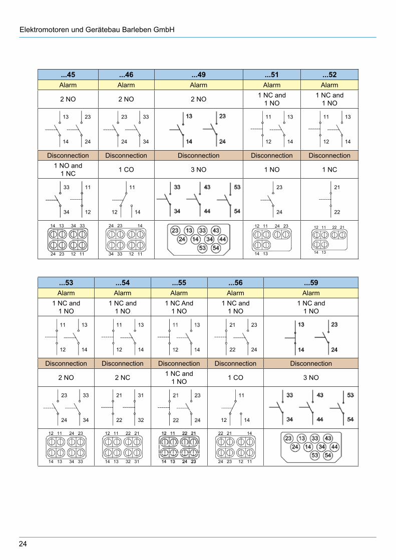
8 Switching system design options for double-float Buchholz relays
Magnet contact tubes are used as switching elements. These are normally-open (NO), normally-closed (NC) and change-over (CO) contacts. The magnet contact tube design can be derived from the last two digits of the type code. For coding, see Ordering data/Type code under Section 12.2.
...11 ...11 (BS 25) ...12 ...13 ...14Alarm Alarm Alarm Alarm Alarm1 NO 1 NO 1 NO 1 NO 1 NO
13
14
13
14
13
14
13
14
13
14
Disconnection Disconnection Disconnectiong Disconnection Disconnection1 NO 1 NO 1 NC 2 NO 2 NC
23
24
23
24
11
12
23
24 34
33 11
12 22
21
...15 ...16 ...17 ...19 ...21Alarm Alarm Alarm Alarm Alarm1 NO 1 NO 1 NO 1 NO 1 NC
13
14
23
24
13
14
13
14
11
12
Disconnection Disconnection Disconnection Disconnection Disconnection1 NO and
1 NC 1 CO 2 CO 3 NO 1 NO
23
24 12
11
14
11
1224
21
22 32
31
34
23
24 34
33
44
4313
14
22
Elektromotoren und Gerätebau Barleben GmbH
...22 ...23 ...24 ...25 ...26Alarm Alarm Alarm Alarm Alarm1 NC 1 NC 1 NC 1 NC 1 NC
11
12
11
12
11
12
11
12
21
22
Disconnection Disconnection Disconnection Disconnection Disconnection
1 NC 2 NO 2 NC 1 NO and 1 NC 1 CO
21
22
13
14 24
23 21
22 32
31 13
14 22
21
14
11
12
...27 ...31 ...32 ...33 ...34Alarm Alarm Alarm Alarm Alarm1 NC 1 CO 1 CO 1 CO 1 CO
11
12 24
21
22 24
21
22 24
21
22 24
21
22
Disconnection Disconnection Disconnection Disconnection Disconnection2 CO 1 NO 1 NC 2 NO 2 NC
24
21
22 32
31
34
13
14
11
12
33
34 44
43 31
32 42
41
23
...35 ...36 ...36 (BS 25) ...37 ...38Alarm Alarm Alarm Alarm Alarm1 CO 1 CO 1 CO 1 CO 1 CO
24
21
22 24
21
22 24
21
22
Disconnection Disconnection Disconnection Disconnection Disconnection1 NO and
1 NC 1 CO 1 CO 2 CO 1 CO and1 NO
13
14 12
11
14
11
12
...3A ...41 ...42 ...43 ...44Alarm Alarm Alarm Alarm Alarm1 CO 2 NO 2 NO 2 NO 2 NO
13
14 24
23 13
14 24
23 13
14 24
23 13
14 24
23
Disconnection Disconnection Disconnection Disconnection Disconnection3 CO 1 NO 1 NC 2 NO 2 NC
33
34
11
12
33
34 44
43 11
12 22
21
14 34 3313
24
Elektromotoren und Gerätebau Barleben GmbH
...45 ...46 ...49 ...51 ...52Alarm Alarm Alarm Alarm Alarm
2 NO 2 NO 2 NO 1 NC and1 NO
1 NC and1 NO
13
14 24
23 23
24 34
33 11
12 14
13 11
12 14
13
Disconnection Disconnection Disconnection Disconnection Disconnection1 NO and
1 NC 1 CO 3 NO 1 NO 1 NC
33
34 12
11
14
11
12
23
24
21
22
...53 ...54 ...55 ...56 ...59Alarm Alarm Alarm Alarm Alarm
1 NC and1 NO
1 NC and1 NO
1 NC And1 NO
1 NC and1 NO
1 NC and1 NO
11
12 14
13 11
12 14
13 21
22 24
23
Disconnection Disconnection Disconnection Disconnection Disconnection
2 NO 2 NC 1 NC and1 NO 1 CO 3 NO
23
24 34
33 21
22 32
31
14
11
12
25
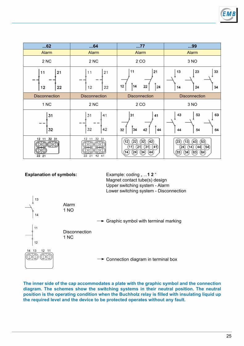
The inner side of the cap accommodates a plate with the graphic symbol and the connection diagram. The schemes show the switching systems in their neutral position. The neutral position is the operating condition when the Buchholz relay is filled with insulating liquid up the required level and the device to be protected operates without any fault.
Explanation of symbols: Example: coding „ ...1 2 “Magnet contact tube(s) design Upper switching system - Alarm Lower switching system - Disconnection
13
14
11
12
Alarm1 NO
Disconnection1 NC
Graphic symbol with terminal marking
Connection diagram in terminal box
...62 ...64 ...77 ...99Alarm Alarm Alarm Alarm
2 NC 2 NC 2 CO 3 NO
Disconnection Disconnection Disconnection Disconnection
1 NC 2 NC 2 CO 3 NO
26
Elektromotoren und Gerätebau Barleben GmbH
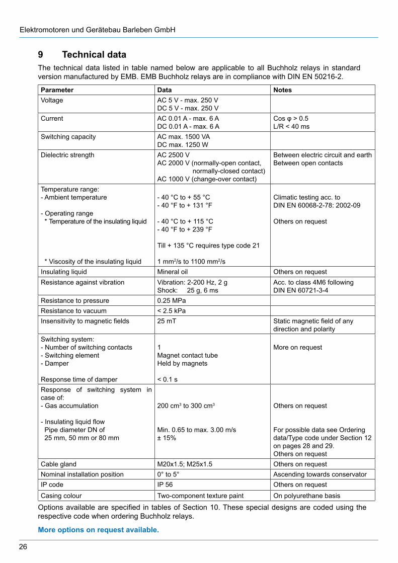
9 Technical data
Parameter Data NotesVoltage AC 5 V - max. 250 V
DC 5 V - max. 250 VCurrent AC 0.01 A - max. 6 A
DC 0.01 A - max. 6 ACos φ > 0.5L/R < 40 ms
Switching capacity AC max. 1500 VADC max. 1250 W
Dielectric strength AC 2500 VAC 2000 V (normally-open contact, normally-closed contact)AC 1000 V (change-over contact)
Between electric circuit and earth Between open contacts
Temperature range: - Ambient temperature
- Operating range * Temperature of the insulating liquid
* Viscosity of the insulating liquid
- 40 °C to + 55 °C- 40 °F to + 131 °F
- 40 °C to + 115 °C- 40 °F to + 239 °F
Till + 135 °C requires type code 21
1 mm2/s to 1100 mm2/s
Climatic testing acc. toDIN EN 60068-2-78: 2002-09
Others on request
Insulating liquid Mineral oil Others on requestResistance against vibration Vibration: 2-200 Hz, 2 g
Shock: 25 g, 6 msAcc. to class 4M6 followingDIN EN 60721-3-4
Resistance to pressure 0.25 MPaResistance to vacuum < 2.5 kPaInsensitivity to magnetic fields 25 mT Static magnetic field of any
direction and polaritySwitching system:- Number of switching contacts - Switching element- Damper
Response time of damper
1Magnet contact tubeHeld by magnets
< 0.1 s
More on request
Response of switching system in case of:- Gas accumulation
- Insulating liquid flow Pipe diameter DN of 25 mm, 50 mm or 80 mm
200 cm3 to 300 cm3
Min. 0.65 to max. 3.00 m/s ± 15%
Others on request
For possible data see Ordering data/Type code under Section 12 on pages 28 and 29. Others on request
Cable gland M20x1.5; M25x1.5 Others on requestNominal installation position 0° to 5° Ascending towards conservatorIP code IP 56 Others on request
Casing colour Two-component texture paint On polyurethane basis
The technical data listed in table named below are applicable to all Buchholz relays in standard version manufactured by EMB. EMB Buchholz relays are in compliance with DIN EN 50216-2.
Options available are specified in tables of Section 10. These special designs are coded using the respective code when ordering Buchholz relays.
More options on request available.
27
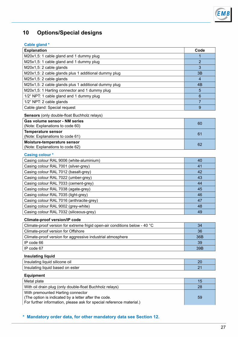
* Mandatory order data, for other mandatory data see Section 12.
10 Options/Special designs
Cable gland *Explanation CodeM20x1,5: 1 cable gland and 1 dummy plug 1M25x1,5: 1 cable gland and 1 dummy plug 2M20x1,5: 2 cable glands 3M20x1,5: 2 cable glands plus 1 additional dummy plug 3BM25x1,5: 2 cable glands 4M25x1,5: 2 cable glands plus 1 additional dummy plug 4BM20x1,5: 1 Harting connector and 1 dummy plug 51/2“ NPT: 1 cable gland and 1 dummy plug 61/2“ NPT: 2 cable glands 7Cable gland: Special request 9
Sensors (only double-float Buchholz relays)Gas volume sensor - NM series(Note: Explanations to code 60) 60
Temperature sensor(Note: Explanations to code 61) 61
Moisture-temperature sensor(Note: Explanations to code 62) 62
Casing colour *Casing colour RAL 9006 (white-aluminium) 40Casing colour RAL 7001 (silver-grey) 41Casing colour RAL 7012 (basalt-grey) 42Casing colour RAL 7022 (umber-grey) 43Casing colour RAL 7033 (cement-grey) 44Casing colour RAL 7038 (agate-grey) 45Casing colour RAL 7035 (light-grey) 46Casing colour RAL 7016 (anthracite-grey) 47Casing colour RAL 9002 (grey-white) 48Casing colour RAL 7032 (siliceous-grey) 49
Climate-proof version/IP codeClimate-proof version for extreme frigid open-air conditions below - 40 °C 34Climate-proof version for Offshore 36Climate-proof version for aggressive industrial atmosphere 36BIP code 66 39IP code 67 39B
Insulating liquidInsulating liquid silicone oil 20Insulating liquid based on ester 21
EquipmentMetal plate 15With oil drain plug (only double-float Buchholz relays) 28With premounted Harting connector(The option is indicated by a letter after the code. For further information, please ask for special reference material.)
59
28
Elektromotoren und Gerätebau Barleben GmbH
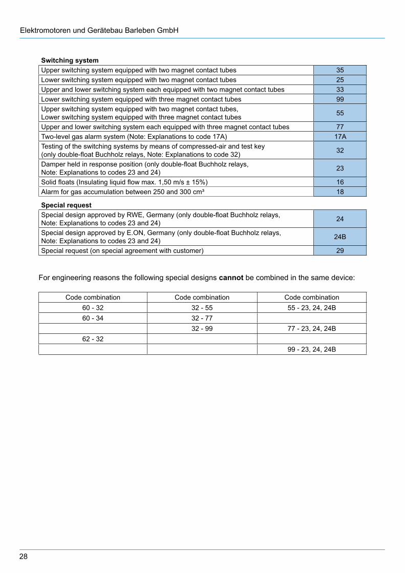
Switching systemUpper switching system equipped with two magnet contact tubes 35Lower switching system equipped with two magnet contact tubes 25Upper and lower switching system each equipped with two magnet contact tubes 33 Lower switching system equipped with three magnet contact tubes 99Upper switching system equipped with two magnet contact tubes, Lower switching system equipped with three magnet contact tubes 55
Upper and lower switching system each equipped with three magnet contact tubes 77Two-level gas alarm system (Note: Explanations to code 17A) 17ATesting of the switching systems by means of compressed-air and test key(only double-float Buchholz relays, Note: Explanations to code 32) 32
Damper held in response position (only double-float Buchholz relays, Note: Explanations to codes 23 and 24) 23
Solid floats (Insulating liquid flow max. 1,50 m/s ± 15%) 16Alarm for gas accumulation between 250 and 300 cm³ 18
Special requestSpecial design approved by RWE, Germany (only double-float Buchholz relays, Note: Explanations to codes 23 and 24) 24
Special design approved by E.ON, Germany (only double-float Buchholz relays,Note: Explanations to codes 23 and 24) 24B
Special request (on special agreement with customer) 29
For engineering reasons the following special designs cannot be combined in the same device:
Code combination Code combination Code combination60 - 32 32 - 55 55 - 23, 24, 24B60 - 34 32 - 77
32 - 99 77 - 23, 24, 24B62 - 32
99 - 23, 24, 24B
29
10.1 Explanations to code 17 A
Gases formed in the transformer rise to the conservator. In this way gases are collected in the Buchholz relay. When a certain volume is reached, the gases generate an alarm signal.
With the two-level alarm system the initial alarm signal is generated at a gas volume of 100-200 cm³, and the second alarm signal at a gas volume of 250-300 cm³. This special design allows a gas sample to be taken for fault analysis already when the initial warning signal is received.
10.2 Explanations to codes 23 and 24/24B
Buchholz relays with the feature „damper held in response position“ are designed such that the damper after it was operated due to an unacceptable high flow rate of the insulating liquid is locked in its position and, hence is kept in this position even after the flow rate has been reduced. This means that the signal generated is maintained.
The damper has to be unlocked manually by turning the test key anticlockwise. When unlocking the damper, also check the insulating liquid level in the Buchholz relay. Bleed the Buchholz relay, if required.
30
Elektromotoren und Gerätebau Barleben GmbH
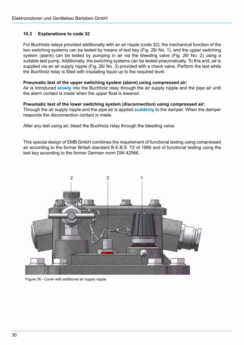
10.3 Explanations to code 32
For Buchholz relays provided additionally with an air nipple (code 32), the mechanical function of the two switching systems can be tested by means of test key (Fig. 26/ No. 1), and the upper switching system (alarm) can be tested by pumping in air via the bleeding valve (Fig. 26/ No. 2) using a suitable test pump. Additionally, the switching systems can be tested pneumatically. To this end, air is supplied via an air supply nipple (Fig. 26/ No. 3) provided with a check valve. Perform the test while the Buchholz relay is filled with insulating liquid up to the required level.
Pneumatic test of the upper switching system (alarm) using compressed air:Air is introduced slowly into the Buchholz relay through the air supply nipple and the pipe air until the alarm contact is made when the upper float is lowered.
Pneumatic test of the lower switching system (disconnection) using compressed air:Through the air supply nipple and the pipe air is applied suddenly to the damper. When the damper responds the disconnection contact is made. After any test using air, bleed the Buchholz relay through the bleeding valve.
This special design of EMB GmbH combines the requirement of functional testing using compressed air according to the former British standard B.E.B.S. T2 of 1966 and of functional testing using the test key according to the former German norm DIN 42566.
Figure 26 - Cover with additional air supply nipple
2 3 1
31
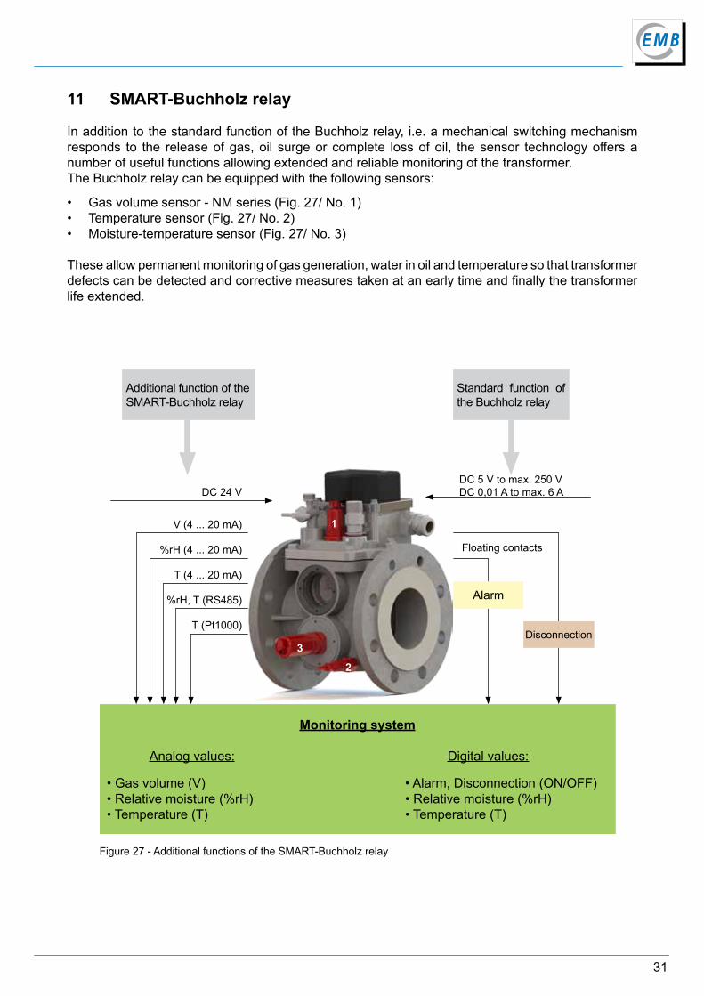
11 SMART-Buchholz relay
In addition to the standard function of the Buchholz relay, i.e. a mechanical switching mechanism responds to the release of gas, oil surge or complete loss of oil, the sensor technology offers a number of useful functions allowing extended and reliable monitoring of the transformer. The Buchholz relay can be equipped with the following sensors:
• Gas volume sensor - NM series (Fig. 27/ No. 1)• Temperature sensor (Fig. 27/ No. 2)• Moisture-temperature sensor (Fig. 27/ No. 3)
These allow permanent monitoring of gas generation, water in oil and temperature so that transformer defects can be detected and corrective measures taken at an early time and finally the transformer life extended.
Additional function of the SMART-Buchholz relay
Standard function of the Buchholz relay
Disconnection
Alarm
DC 24 V
V (4 ... 20 mA)
%rH (4 ... 20 mA)
T (4 ... 20 mA)
%rH, T (RS485)
Monitoring system
Analog values: Digital values:
• Gas volume (V) • Alarm, Disconnection (ON/OFF)• Relative moisture (%rH) • Relative moisture (%rH)• Temperature (T) • Temperature (T)
T (Pt1000)
Figure 27 - Additional functions of the SMART-Buchholz relay
DC 5 V to max. 250 VDC 0,01 A to max. 6 A
1
3
2
Floating contacts
32
Elektromotoren und Gerätebau Barleben GmbH
11.1.2 Additional function of Buchholz relay with gas volume sensor
The standard Buchholz relay detects unsolved gases in the insulating liquid and generates a signal indicating the presence of gases when the specified threshold is exceeded, i.e. up to a certain gas volume no signal is generated. It does not allow conclusions with regard to the time of generation of gases.
The time of the generation of unsolved gases in the insulating liquid is a significant criterion for the evaluation of the defect. The composition and volume of the fault gases depend on the type and energy content of the defect leading to the generation of gases. Spontaneous and high-energy faults cause significant gas volumes within a short period of time whilst minor and low-energy faults produce low gas volumes.
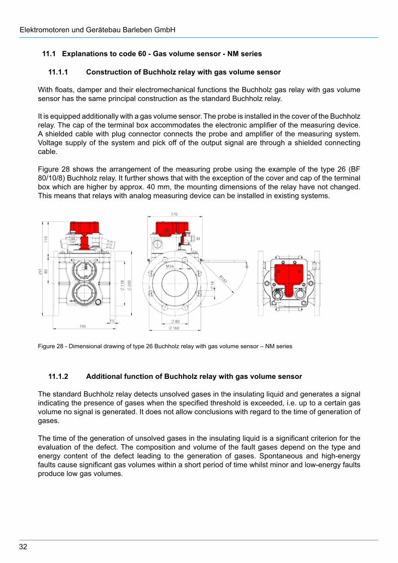
Figure 28 - Dimensional drawing of type 26 Buchholz relay with gas volume sensor – NM series
11.1 Explanations to code 60 - Gas volume sensor - NM series
11.1.1 Construction of Buchholz relay with gas volume sensor
With floats, damper and their electromechanical functions the Buchholz gas relay with gas volume sensor has the same principal construction as the standard Buchholz relay.
It is equipped additionally with a gas volume sensor. The probe is installed in the cover of the Buchholz relay. The cap of the terminal box accommodates the electronic amplifier of the measuring device. A shielded cable with plug connector connects the probe and amplifier of the measuring system. Voltage supply of the system and pick off of the output signal are through a shielded connecting cable.
Figure 28 shows the arrangement of the measuring probe using the example of the type 26 (BF 80/10/8) Buchholz relay. It further shows that with the exception of the cover and cap of the terminal box which are higher by approx. 40 mm, the mounting dimensions of the relay have not changed. This means that relays with analog measuring device can be installed in existing systems.
33
Continuous and analog measurements in the Buchholz relay by the gas volume sensor supply information about the development of unsolved gases which allow early evaluation of the defect.
The additional function is realised by a gas volume sensor with capacitive action. The supply voltage of this component is 24 V DC provided by the user. The output signal is a current signal of 4 to 20 mA DC. Processing of the information supplied by this standardised signal is the user’s responsibility.
11.1.3 Analog measuring device - analog gas volume measurement
The measured value is based on capacity changes of the measuring probe caused by variation of the insulating liquid level in the Buchholz relay.
Gas volumes between 50 and 300 cm³ are measured analogously. The design of the device does not allow precise measurement of lower gas volumes. Due to the response of the top switching system volumes in excess of the above need not be measured and cannot be measured because of the design of the Buchholz relay (higher gas volumes are diverted to the conservator). The operating point of the top switching system (top float) is a gas volume between 200 and 300 cm³.
Fault: The insulating liquid contains unsolved gas.
Reaction: The gas in the liquid moves upwards, accumulates in the Buchholz relay and displaces the insulating liquid. This causes the insulating liquid level to fall. As the filling level changes, the capacity of the measuring probe changes. An analog current signal is generated that corresponds to the extent of the capacity variation.
It should be noted that for design reasons the current value of the probe remains relatively constant up to a gas volume of approx. 50 cm³. It is only when the current signal becomes smaller and hence the calculated gas volume increases clearly, that the actual volume can be derived from the course of the characteristic of the analog measuring system.
34
Elektromotoren und Gerätebau Barleben GmbH
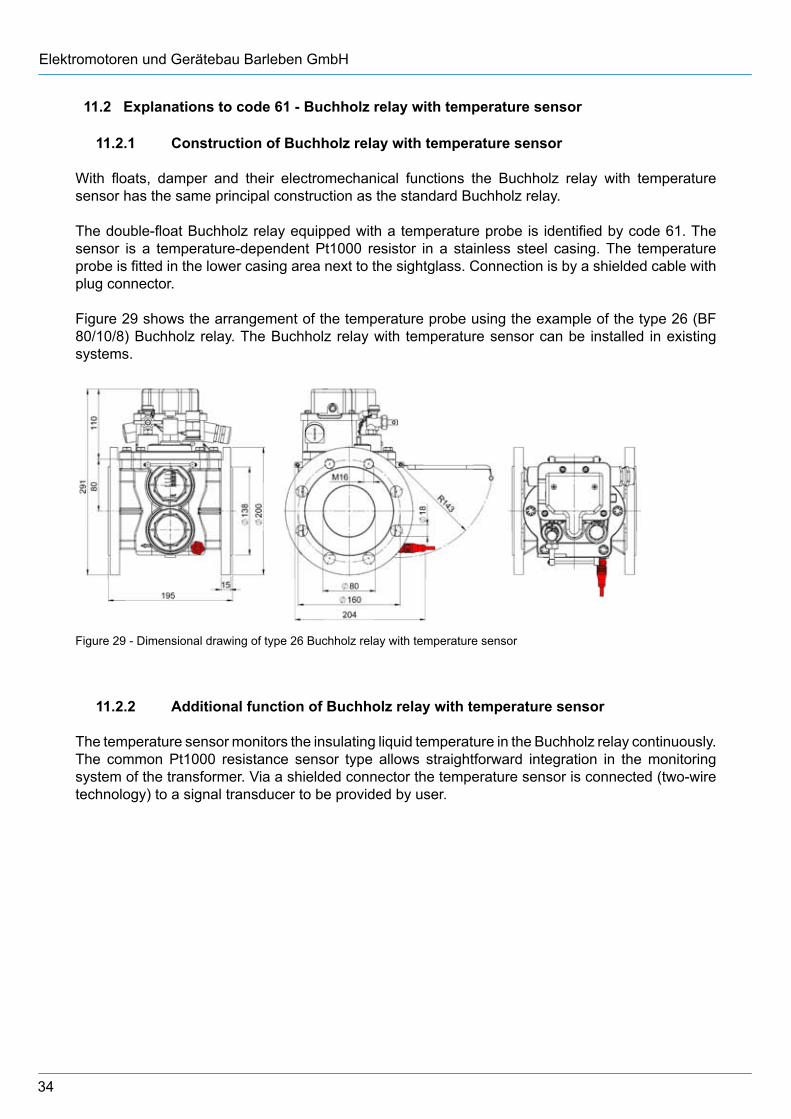
11.2 Explanations to code 61 - Buchholz relay with temperature sensor
11.2.1 Construction of Buchholz relay with temperature sensor
With floats, damper and their electromechanical functions the Buchholz relay with temperature sensor has the same principal construction as the standard Buchholz relay.
The double-float Buchholz relay equipped with a temperature probe is identified by code 61. The sensor is a temperature-dependent Pt1000 resistor in a stainless steel casing. The temperature probe is fitted in the lower casing area next to the sightglass. Connection is by a shielded cable with plug connector.
Figure 29 shows the arrangement of the temperature probe using the example of the type 26 (BF 80/10/8) Buchholz relay. The Buchholz relay with temperature sensor can be installed in existing systems.
Figure 29 - Dimensional drawing of type 26 Buchholz relay with temperature sensor
11.2.2 Additional function of Buchholz relay with temperature sensor
The temperature sensor monitors the insulating liquid temperature in the Buchholz relay continuously. The common Pt1000 resistance sensor type allows straightforward integration in the monitoring system of the transformer. Via a shielded connector the temperature sensor is connected (two-wire technology) to a signal transducer to be provided by user.
35
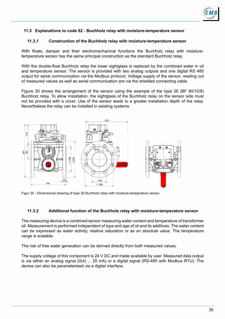
11.3 Explanations to code 62 - Buchholz relay with moisture-temperature sensor
11.3.1 Construction of the Buchholz relay with moisture-temperature sensor
With floats, damper and their electromechanical functions the Buchholz relay with moisture-temperature sensor has the same principal construction as the standard Buchholz relay.
With the double-float Buchholz relay the lower sightglass is replaced by the combined water in oil and temperature sensor. The sensor is provided with two analog outputs and one digital RS 485 output for serial communication via the Modbus protocol. Voltage supply of the sensor, reading out of measured values as well as serial communication are via the shielded connecting cable.
Figure 30 shows the arrangement of the sensor using the example of the type 26 (BF 80/10/8) Buchholz relay. To allow installation, the sightglass of the Buchholz relay on the sensor side must not be provided with a cover. Use of the sensor leads to a greater installation depth of the relay. Nevertheless the relay can be installed in existing systems.
Figur 30 - Dimensional drawing of type 26 Buchholz relay with moisture-temperature sensor
11.3.2 Additional function of the Buchholz relay with moisture-temperature sensor
The measuring device is a combined sensor measuring water content and temperature of transformer oil. Measurement is performed independent of type and age of oil and its additives. The water content can be expressed as water activity, relative saturation or as an absolute value. The temperature range is scalable.
The risk of free water generation can be derived directly from both measured values.
The supply voltage of this component is 24 V DC and made available by user. Measured data output is via either an analog signal (0(4) ... 20 mA) or a digital signal (RS-485 with Modbus RTU). The device can also be parameterised via a digital interface.
36
Elektromotoren und Gerätebau Barleben GmbH
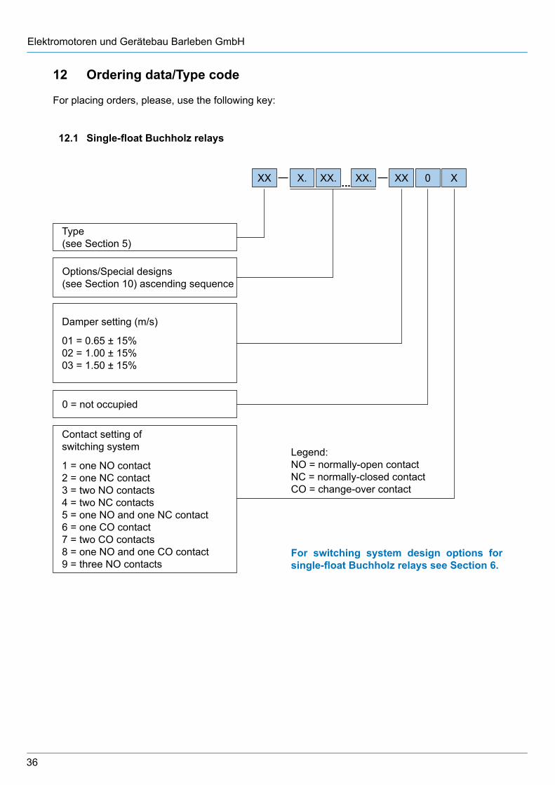
12 Ordering data/Type code
For placing orders, please, use the following key:
12.1 Single-float Buchholz relays
Type (see Section 5)
Options/Special designs (see Section 10) ascending sequence
0 = not occupied
Damper setting (m/s)
01 = 0.65 ± 15% 02 = 1.00 ± 15% 03 = 1.50 ± 15%
Contact setting of switching system
1 = one NO contact 2 = one NC contact 3 = two NO contacts 4 = two NC contacts 5 = one NO and one NC contact 6 = one CO contact 7 = two CO contacts 8 = one NO and one CO contact 9 = three NO contacts
XX X. XX. XX X0XX.
For switching system design options for single-float Buchholz relays see Section 6.
Legend:NO = normally-open contactNC = normally-closed contactCO = change-over contact
37
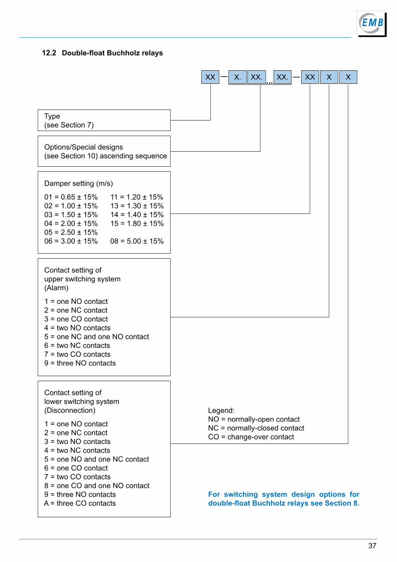
For switching system design options for double-float Buchholz relays see Section 8.
Type (see Section 7)
Options/Special designs (see Section 10) ascending sequence
Damper setting (m/s)
01 = 0.65 ± 15% 11 = 1.20 ± 15% 02 = 1.00 ± 15% 13 = 1.30 ± 15% 03 = 1.50 ± 15% 14 = 1.40 ± 15% 04 = 2.00 ± 15% 15 = 1.80 ± 15% 05 = 2.50 ± 15% 06 = 3.00 ± 15% 08 = 5.00 ± 15%
Contact setting of lower switching system (Disconnection)
1 = one NO contact 2 = one NC contact 3 = two NO contacts 4 = two NC contacts 5 = one NO and one NC contact 6 = one CO contact 7 = two CO contacts 8 = one CO and one NO contact 9 = three NO contacts A = three CO contacts
Contact setting of upper switching system (Alarm)
1 = one NO contact 2 = one NC contact 3 = one CO contact 4 = two NO contacts 5 = one NC and one NO contact 6 = two NC contacts 7 = two CO contacts 9 = three NO contacts
XX XX XXX. XX.XX.
12.2 Double-float Buchholz relays
Legend:NO = normally-open contactNC = normally-closed contactCO = change-over contact
38
Elektromotoren und Gerätebau Barleben GmbH
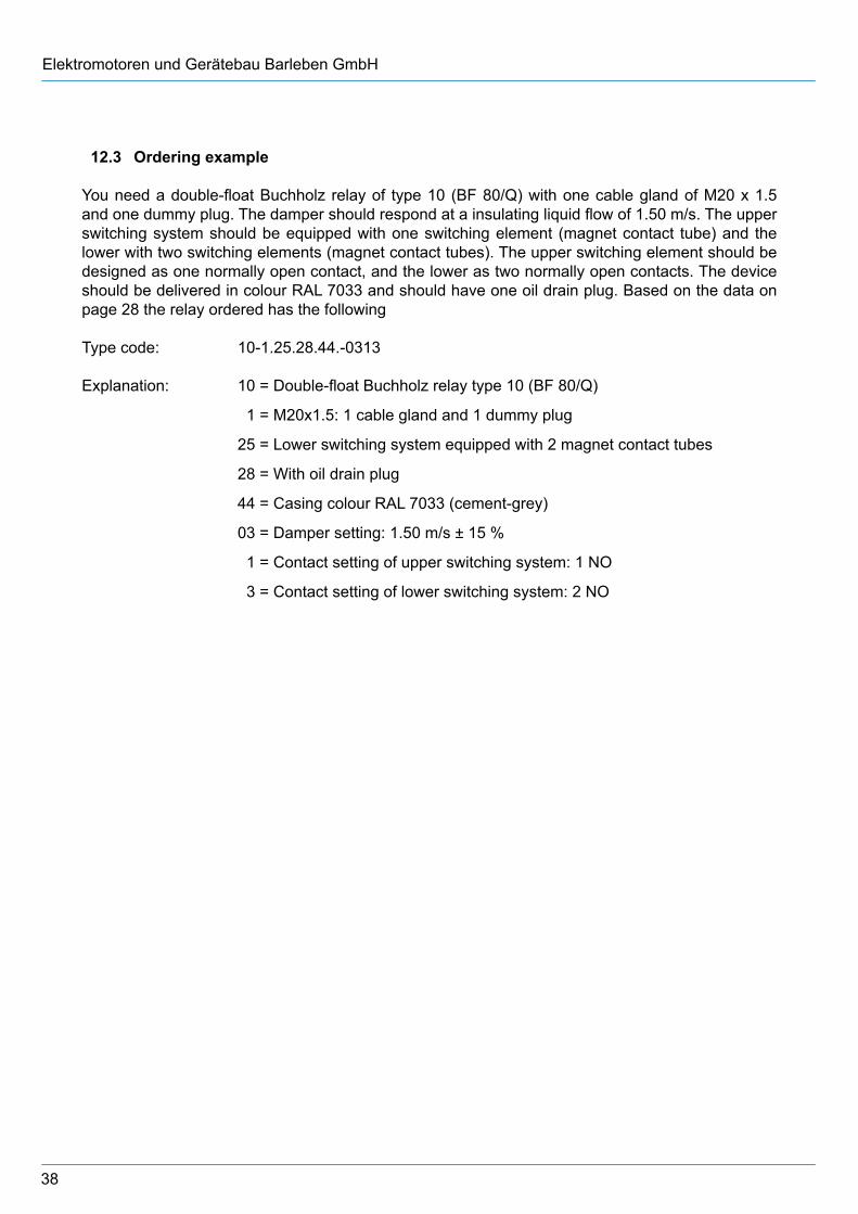
12.3 Ordering example
You need a double-float Buchholz relay of type 10 (BF 80/Q) with one cable gland of M20 x 1.5 and one dummy plug. The damper should respond at a insulating liquid flow of 1.50 m/s. The upper switching system should be equipped with one switching element (magnet contact tube) and the lower with two switching elements (magnet contact tubes). The upper switching element should be designed as one normally open contact, and the lower as two normally open contacts. The device should be delivered in colour RAL 7033 and should have one oil drain plug. Based on the data on page 28 the relay ordered has the following
Type code: 10-1.25.28.44.-0313
Explanation: 10 = Double-float Buchholz relay type 10 (BF 80/Q)
1 = M20x1.5: 1 cable gland and 1 dummy plug
25 = Lower switching system equipped with 2 magnet contact tubes
28 = With oil drain plug
44 = Casing colour RAL 7033 (cement-grey)
03 = Damper setting: 1.50 m/s ± 15 %
1 = Contact setting of upper switching system: 1 NO
3 = Contact setting of lower switching system: 2 NO
39
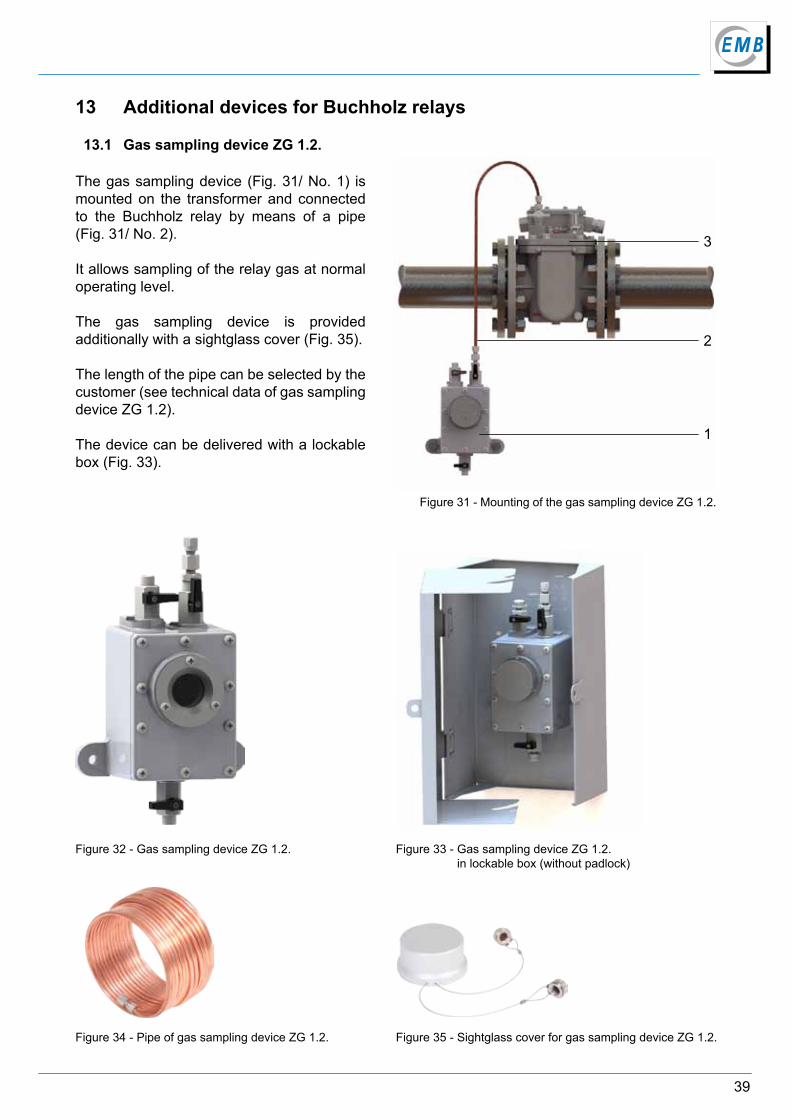
13 Additional devices for Buchholz relays
13.1 Gas sampling device ZG 1.2.
The gas sampling device (Fig. 31/ No. 1) is mounted on the transformer and connected to the Buchholz relay by means of a pipe (Fig. 31/ No. 2).
It allows sampling of the relay gas at normal operating level.
The gas sampling device is provided additionally with a sightglass cover (Fig. 35).
The length of the pipe can be selected by the customer (see technical data of gas sampling device ZG 1.2).
The device can be delivered with a lockable box (Fig. 33).
Figure 31 - Mounting of the gas sampling device ZG 1.2.
Figure 32 - Gas sampling device ZG 1.2. Figure 33 - Gas sampling device ZG 1.2. in lockable box (without padlock)
Figure 34 - Pipe of gas sampling device ZG 1.2. Figure 35 - Sightglass cover for gas sampling device ZG 1.2.
1
3
2
40
Elektromotoren und Gerätebau Barleben GmbH
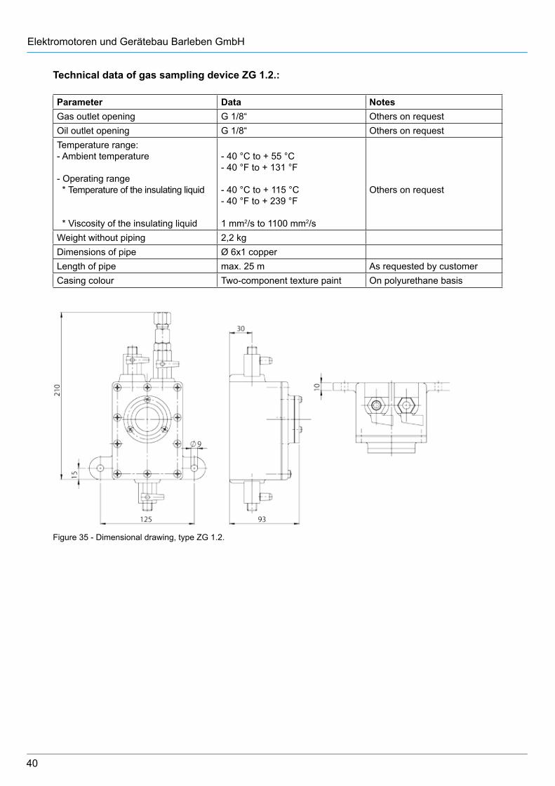
Technical data of gas sampling device ZG 1.2.:
Parameter Data NotesGas outlet opening G 1/8“ Others on requestOil outlet opening G 1/8“ Others on requestTemperature range: - Ambient temperature
- Operating range * Temperature of the insulating liquid
* Viscosity of the insulating liquid
- 40 °C to + 55 °C- 40 °F to + 131 °F
- 40 °C to + 115 °C- 40 °F to + 239 °F
1 mm2/s to 1100 mm2/s
Others on request
Weight without piping 2,2 kgDimensions of pipe Ø 6x1 copperLength of pipe max. 25 m As requested by customerCasing colour Two-component texture paint On polyurethane basis
Figure 35 - Dimensional drawing, type ZG 1.2.
41
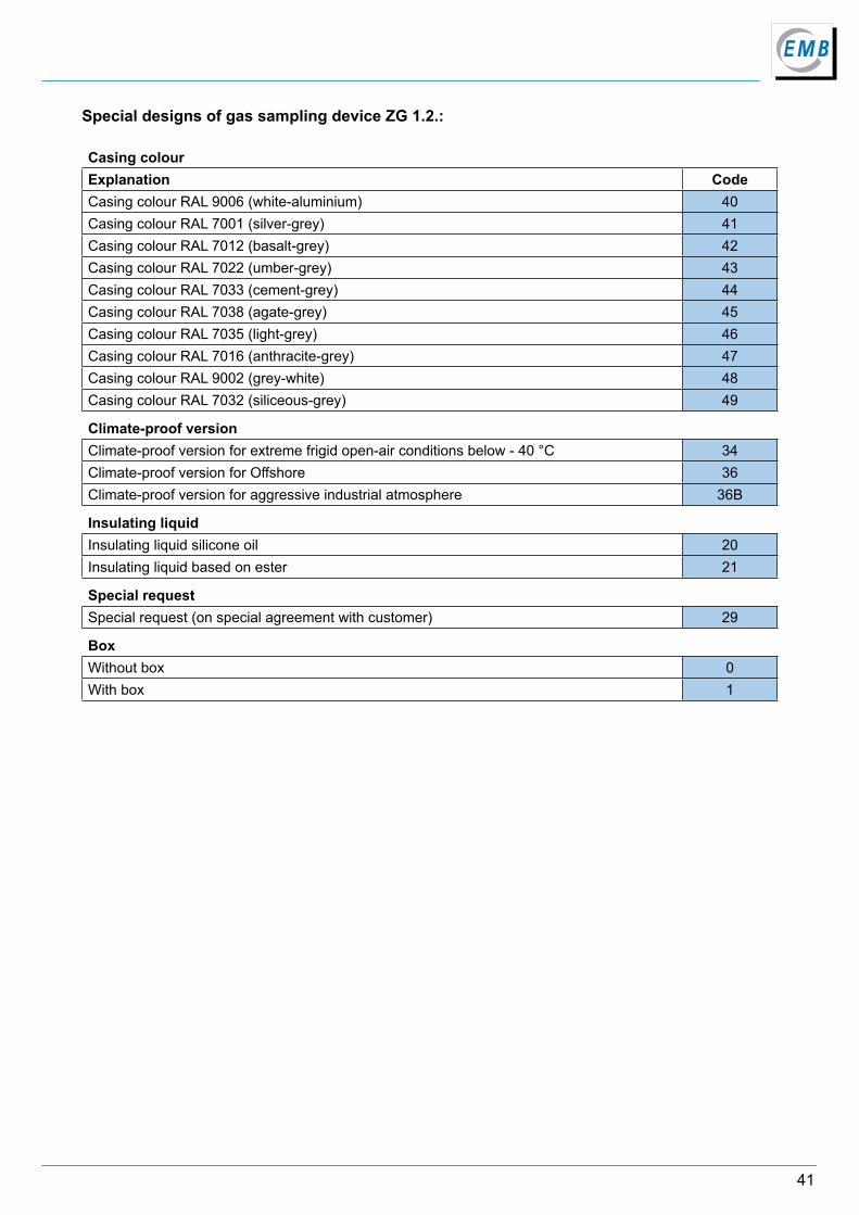
Special designs of gas sampling device ZG 1.2.:
Casing colourExplanation CodeCasing colour RAL 9006 (white-aluminium) 40Casing colour RAL 7001 (silver-grey) 41Casing colour RAL 7012 (basalt-grey) 42Casing colour RAL 7022 (umber-grey) 43Casing colour RAL 7033 (cement-grey) 44Casing colour RAL 7038 (agate-grey) 45Casing colour RAL 7035 (light-grey) 46Casing colour RAL 7016 (anthracite-grey) 47Casing colour RAL 9002 (grey-white) 48Casing colour RAL 7032 (siliceous-grey) 49
Climate-proof versionClimate-proof version for extreme frigid open-air conditions below - 40 °C 34Climate-proof version for Offshore 36Climate-proof version for aggressive industrial atmosphere 36B
Insulating liquidInsulating liquid silicone oil 20Insulating liquid based on ester 21
Special requestSpecial request (on special agreement with customer) 29
BoxWithout box 0With box 1
42
Elektromotoren und Gerätebau Barleben GmbH
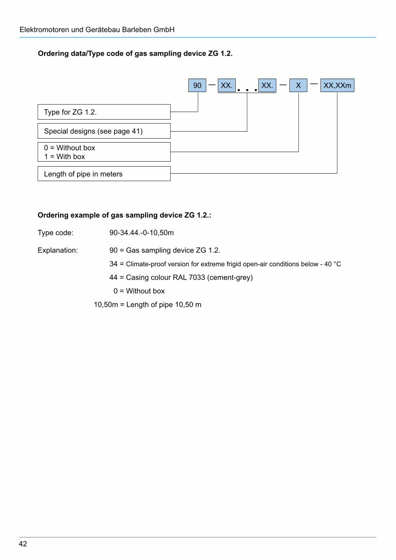
Ordering data/Type code of gas sampling device ZG 1.2.
Type for ZG 1.2.
Special designs (see page 41)
0 = Without box 1 = With box
90 XX. XX. X XX,XXm
Length of pipe in meters
Ordering example of gas sampling device ZG 1.2.:
Type code: 90-34.44.-0-10,50m
Explanation: 90 = Gas sampling device ZG 1.2.
34 = Climate-proof version for extreme frigid open-air conditions below - 40 °C
44 = Casing colour RAL 7033 (cement-grey)
0 = Without box
10,50m = Length of pipe 10,50 m

43
Buchholz gas sampler BGS
The Buchholz gas sampler provides a safe method of taking and transporting gas samples from the Buchholz relay or the gas sampling device. Its capacity is 100 ml.
Buchholz gas testers BGT 4.1 and BGT 4.2
The Buchholz gas tester is used to measure and analyse the free gases in the oil which have accumulated in the Buchholz relay.
The BGT 4.1 is used to measure the hydrogen concentration in the Buchholz gas.
The BGT 4.2 allows the measurement of hydrogen, carbon dioxide, carbon monoxide, total hydrocarbon and ethyne concentrations in the Buchholz gas.
A BGS is included in the scope of delivery.
Gas testing device ZG 3.1.
The gas testing device is used to test the gas accumulated in the Buchholz relay. It can be installed either directly on the bleeding valve of the Buchholz relay or on the gas outlet tap of the gas sampling device. The Buchholz gas flows through two different chemical solutions and its colour reactions indicate the nature of the fault.
Use of the gas testing device is no substitute for a gas chromatographic analysis.
Gas testing device ZG 3.2.
The gas testing device ZG 3.2. provides a quick test for extended monitoring of transformer gases. A qualitative analysis for the presence of hydrogen and carbon monoxide is carried out.
The gas testing device can only be used in combination with the BGS thus ensuring higher flexibility and free selection of the place of testing.
13.2 Other additional devices for Buchholz relays
For further information on the additional devices, please ask for special reference material.
44
Elektromotoren und Gerätebau Barleben GmbH
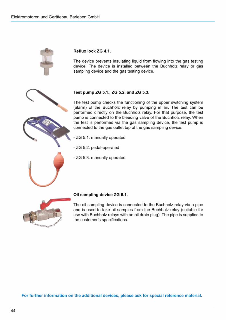
Reflux lock ZG 4.1.
The device prevents insulating liquid from flowing into the gas testing device. The device is installed between the Buchholz relay or gas sampling device and the gas testing device.
Test pump ZG 5.1., ZG 5.2. and ZG 5.3.
The test pump checks the functioning of the upper switching system (alarm) of the Buchholz relay by pumping in air. The test can be performed directly on the Buchholz relay. For that purpose, the test pump is connected to the bleeding valve of the Buchholz relay. When the test is performed via the gas sampling device, the test pump is connected to the gas outlet tap of the gas sampling device.
- ZG 5.1. manually operated
- ZG 5.2. pedal-operated
- ZG 5.3. manually operated
Oil sampling device ZG 6.1.
The oil sampling device is connected to the Buchholz relay via a pipe and is used to take oil samples from the Buchholz relay (suitable for use with Buchholz relays with an oil drain plug). The pipe is supplied to the customer’s specifications.
For further information on the additional devices, please ask for special reference material.
45
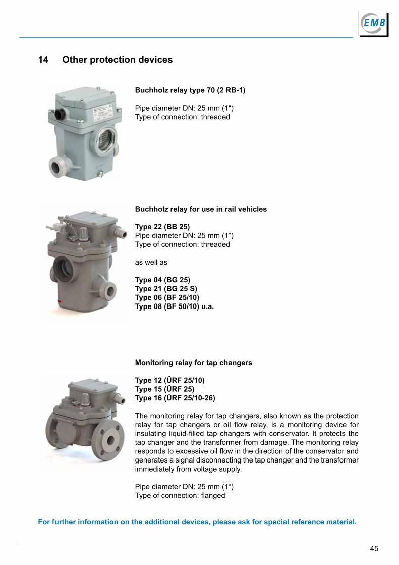
Buchholz relay type 70 (2 RB-1)
Pipe diameter DN: 25 mm (1“)Type of connection: threaded
Buchholz relay for use in rail vehicles
Type 22 (BB 25)Pipe diameter DN: 25 mm (1“)Type of connection: threaded
as well as
Type 04 (BG 25)Type 21 (BG 25 S)Type 06 (BF 25/10) Type 08 (BF 50/10) u.a.
Monitoring relay for tap changers
Type 12 (ÜRF 25/10)Type 15 (ÜRF 25)Type 16 (ÜRF 25/10-26)
The monitoring relay for tap changers, also known as the protection relay for tap changers or oil flow relay, is a monitoring device for insulating liquid-filled tap changers with conservator. It protects the tap changer and the transformer from damage. The monitoring relay responds to excessive oil flow in the direction of the conservator and generates a signal disconnecting the tap changer and the transformer immediately from voltage supply.
Pipe diameter DN: 25 mm (1“)Type of connection: flanged
14 Other protection devices
For further information on the additional devices, please ask for special reference material.
46
Elektromotoren und Gerätebau Barleben GmbH
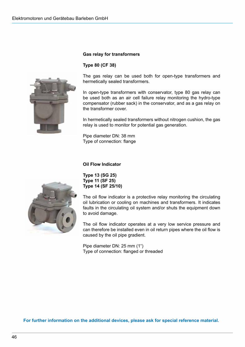
Gas relay for transformers
Type 80 (CF 38)
The gas relay can be used both for open-type transformers and hermetically sealed transformers.
In open-type transformers with conservator, type 80 gas relay can be used both as an air cell failure relay monitoring the hydro-type compensator (rubber sack) in the conservator, and as a gas relay on the transformer cover.
In hermetically sealed transformers without nitrogen cushion, the gas relay is used to monitor for potential gas generation.
Pipe diameter DN: 38 mm Type of connection: flange
Oil Flow Indicator
Type 13 (SG 25)Type 11 (SF 25)Type 14 (SF 25/10)
The oil flow indicator is a protective relay monitoring the circulating oil lubrication or cooling on machines and transformers. It indicates faults in the circulating oil system and/or shuts the equipment down to avoid damage.
The oil flow indicator operates at a very low service pressure and can therefore be installed even in oil return pipes where the oil flow is caused by the oil pipe gradient.
Pipe diameter DN: 25 mm (1“)Type of connection: flanged or threaded
For further information on the additional devices, please ask for special reference material.
47
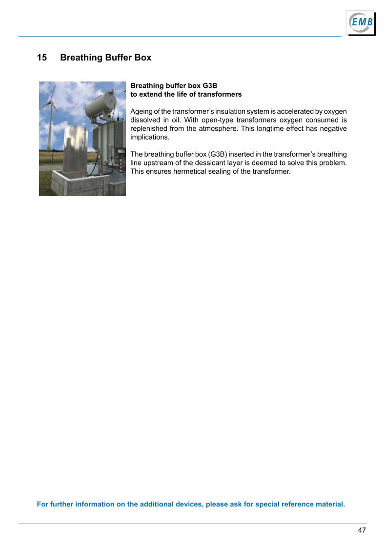
15 Breathing Buffer Box
Breathing buffer box G3Bto extend the life of transformers
Ageing of the transformer’s insulation system is accelerated by oxygen dissolved in oil. With open-type transformers oxygen consumed is replenished from the atmosphere. This longtime effect has negative implications.
The breathing buffer box (G3B) inserted in the transformer’s breathing line upstream of the dessicant layer is deemed to solve this problem. This ensures hermetical sealing of the transformer.
For further information on the additional devices, please ask for special reference material.
Due to technical improvement of our products, the information contained in this catalogue is subject to change without notice. We would like to apologize for printing errors which have not been found despite intensive proof-ready. We assume no liability for such errors. Thank you for your understanding.
Edition: Catalogue Buchholz relays KA 01/01/18/02 English
EMB GmbHOtto-von-Guericke-Allee 12D-39179 Barleben | Germany
Phone: +49 39203 790Fax: +49 39203 5330
Email: [email protected]: www.emb-online.de www.buchholzrelay.com
Hamburg
Hannover
Köln
Frankfurt
München
Berlin
Leipzig
Barleben
Magdeburg
Elektromotoren undGerätebau Barleben GmbH