Transformation of the Mechanical Properties of Fiber-Reinforced Plastic … · ·...
16
Athens Journal of Technology & Engineering March 2017 47 Transformation of the Mechanical Properties of Fiber-Reinforced Plastic Tubes from the Cartesian Coordinate System into the Cylindrical Coordinate System for the Application of Bending Models By Marco Siegl Ingo Ehrlich ‡ Fiber-reinforced plastic (FRP) tubes are used in many different industries, such as electrical engineering and pipeline construction. The tubes are frequently subjected to bending loads, depending on the application. In order that the dimensioning of the tubes can be ensured, analytical bending models are used to calculate the resulting stresses, strains and displacements in the individual layers of the laminate. This enables the making of a statement about the failure of the fiber-reinforced tube by choosing an appropriate failure criterion. For the use of these bending models, it is necessary to understand the respective underlying theory. The theory provides the basis for the mathematical description of the mechanical properties for a single-layered tube and using the relationships between the stresses and strains that occur in the Cylindrical coordinate system for this calculation step. For this reason, a redefinition of the compliance matrix from the transformation about the winding angle to the Cylindrical coordinate system and a modification of the stress and strain vectors is necessary, because the defined Cartesian coordinate system of the model cannot be used for wounded FRP tubes. The transformation causes an exchange of entries in the compliance matrix, which remain in the correct relationship between the particular stress and strains. This step is not specified and may lead to incorrect results due to the incorrect entry of compliances. The present publication refers to sketch on this issue and represent a simplification of the changeover to the level required by the bending models notation of vectors in the form of a permutation. In addition, a new name for the pre-acquisition of the redefined compliances is given to prevent confusion when entering the material law of a bending model. Finally, the permuted and redefined compliances are proved in an example to determine their accuracy. Keywords: Bending model, Cylindrical coordinate system, Fiber-reinforced plastic tubes, Permutation of the compliances, Transformation of the compliances. PhD Student, Ostbayerische Technische Hochschule (OTH) Regensburg, Germany. ‡ Professor, Ostbayerische Technische Hochschule (OTH) Regensburg, Germany.
Transcript of Transformation of the Mechanical Properties of Fiber-Reinforced Plastic … · ·...

Athens Journal of Technology & Engineering March 2017
47
Transformation of the Mechanical Properties of
Fiber-Reinforced Plastic Tubes from the Cartesian
Coordinate System into the Cylindrical Coordinate
System for the Application of Bending Models
By Marco Siegl
Ingo Ehrlich‡
Fiber-reinforced plastic (FRP) tubes are used in many different industries, such
as electrical engineering and pipeline construction. The tubes are frequently
subjected to bending loads, depending on the application. In order that the
dimensioning of the tubes can be ensured, analytical bending models are used to
calculate the resulting stresses, strains and displacements in the individual layers
of the laminate. This enables the making of a statement about the failure of the
fiber-reinforced tube by choosing an appropriate failure criterion. For the use of
these bending models, it is necessary to understand the respective underlying
theory. The theory provides the basis for the mathematical description of the
mechanical properties for a single-layered tube and using the relationships
between the stresses and strains that occur in the Cylindrical coordinate system
for this calculation step. For this reason, a redefinition of the compliance matrix
from the transformation about the winding angle to the Cylindrical coordinate
system and a modification of the stress and strain vectors is necessary, because
the defined Cartesian coordinate system of the model cannot be used for wounded
FRP tubes. The transformation causes an exchange of entries in the compliance
matrix, which remain in the correct relationship between the particular stress and
strains. This step is not specified and may lead to incorrect results due to the
incorrect entry of compliances. The present publication refers to sketch on this
issue and represent a simplification of the changeover to the level required by the
bending models notation of vectors in the form of a permutation. In addition, a
new name for the pre-acquisition of the redefined compliances is given to prevent
confusion when entering the material law of a bending model. Finally, the
permuted and redefined compliances are proved in an example to determine their
accuracy.
Keywords: Bending model, Cylindrical coordinate system, Fiber-reinforced
plastic tubes, Permutation of the compliances, Transformation of the compliances.
PhD Student, Ostbayerische Technische Hochschule (OTH) Regensburg, Germany. ‡ Professor, Ostbayerische Technische Hochschule (OTH) Regensburg, Germany.

Vol. 4, No. 1 Siegl et al.: Transformation of the Mechanical Properties…
48
Introduction
Fiber-reinforced plastics represent a major constituent in lightweight
construction and are utilized increasingly in the industry due to their excellent
properties. The specific strength and specific stiffness of FRPs exceed those of
high-alloyed steels or light materials such as aluminum. FRP materials are mainly
used in industries such as aviation and space technology, in which a weight-
minimization with simultaneous fulfillment of mechanical requirements is
demanded for design goals. This leads to savings concerning the accelerating
mass, thus allowing for greater drive power or payloads. This implies that FRPs
are ideal lightweight materials for engineering components, which undergo
acceleration or deceleration, which is the case in aerospace engineering,
automotive and maritime engineering. In addition, dynamically moving
components in general engineering applications can be produced with this
lightweight construction to energetically optimize machines.
Due to the high chemical resistance, FRPs are also used for equipment and
pipeline construction in corrosive environment applications. The non-conducting
properties of glass fibers enables the use of glass-fiber-reinforced plastics (GFRP)
as insulators and switches in the electrical industry. In many of these industrial
sectors, axially symmetric structures made of FRP are used. For example, a fluid
has to flow through or a machine operates in the interior and has to be sealed with
gas. Furthermore, these tubular structures are subjected to bending caused by e. g.
wind loads or module-specific design elements. The calculation of the stresses and
deformations of FRPs under the described bending load is very challenging
because of the anisotropy of the material and the multi-layered structure of the
composite. Nevertheless, there are some calculation models for fiber-reinforced
tubes, which are based on the definition of the linear-elastic material properties of
a single layer and the associated coordinate system.
After this step, the mathematical theory of cylindrical anisotropic elasticity by
Lekhnitskii (1963) can be specified. This includes the set-up of the basic
equations for the strain-displacement relations for a tube with an orthotropic
single layer, an indication of the stress relationships and their equilibrium
conditions. In addition to that, two systems from the relationships and material
properties are generated in the form of partial differential equations over stress
functions through whether the bending problem or the tensile, torsion and pressure
problem can be solved. Jolicoeur and Cardou (1994) established a general
analytical solution based on the work of Lekhnitskii (1963) for stresses and
displacements of a multi-layered tube, in which the individual layers are
composed of orthotropic material and the boundary conditions between the
individual layers and on the outer surfaces are defined. They also noted a
deformation of the circular cross section due to bending stress, for which reason
the Bernoulli-Euler hypothesis is strictly not allowed to be used for FRP
cylinders. Chouchaoui and Ochoa (1999) used similar constitutive equations as
Jolicoeur and Cardou (1994), but they considered only perfect bonding between
the layers in comparison to Jolicoeur and Cardou (1994), who differentiated slip
and friction as boundary condition. Both publications are predicted on the

Athens Journal of Technology & Engineering March 2017
49
assumption that the loading case for bending is defined with two moments acting
at the ends of the tube, so that a constant curvature is resulting along the
longitudinal tube axis. Therefore the equivalent flexural stiffness < > for the
multi-layered tube can be calculated. Tarn and Wang (2001) presented a state
space approach to the bending of the laminated composite tubes. Here, the system
matrix in the Cylindrical coordinate system is independent of the radius , because
of a judicious arrangement of the displacement and stress variables. Thus, the
calculation process is followed by a reduction of the large system of equations for
the stress and displacement expressions. Derisi (2008) used the flexural stiffness
to describe a cantilever beam of FRP with a transverse force at the free end to
calculate the deflection. Shadmehri et al. (2011) exhibited another way for
defining the equivalent bending stiffness < >, which is a function of the radius
and the laminate stiffness coefficients for anisotropic materials. In addition to the
described warping of the cross section by Jolicoeur and Cardou (1994), also
warping inhibition, transverse shear deformation and non-uniform twist on
composite tubes occurs. Due to these effects, therein the referenced non-classical
composite beam theory is used to define the equivalent bending stiffness < >.
Derisi et al. (2012) also used the non-classical laminate theory to define the
equivalent bending stiffness < >, because the system of equations would be
large for many layers. Instead, this investigation compared the flexural stiffness of
three-point-bending tests for three different composite tubes with an analogous
aluminum tube and the calculated flexural stiffness. A new simulation technique
was also presented and has been proved with experimental results. Geuchy
Ahmad and Hoa (2016) validated the analytical equivalent flexural stiffness < >
according to Jolicoeur and Cardou (1994) with experiments on two thick walled
composite tubes. They used a pure bending test setup without concentrated
loading points in the force introduction as in three- or four-point bending tests,
which is developed by Shadmehri (2012). Here, the tube is fixed inside the
bending facility with low melting point alloy. To realize the required bending
moment at each end of the tube, the construction includes two hydraulic cylinders
and moment-arm assemblies. The deformation behavior was measured with strain
gauges at different locations of the tube and speckle pattern to exploit the surface
deformation also with a Digital Image Correlation measurement system. The
experimental results correlate to the analytic bending stiffness by Jolicoeur and
Cardou (1994), but with only two specimens the experiment does not provide an
adequate statistical coverage. Sarvestani et al. (2016) presented a new high-order
displacement-based method for thick cantilever tubes under transverse loading,
which has a good match with the experimental data, which are generated with a
three-point bending test, FEM and the Lekhnitskii (1963) solution with a [0°]
composite tube, because Lekhnitskii only examines single layer cylinders with
monolithic homogeneous orthotropic cylindrical shells. The method was also
based on the equation of Lekhnitskii (1963), but they used a layer-wise theory
with Lagrangian linear interpolation functions, because of the thick composite
tubes, and using the principle of minimum total potential energy to get the
equilibrium equations of a laminated orthotropic straight tube.

Vol. 4, No. 1 Siegl et al.: Transformation of the Mechanical Properties…
50
Analysis
A correct material definition requires a strict distinction between the
Cartesian, the Cylindrical coordinate system and the coordinate system that
defines the external loads. A unidirectional (UD) composite layer is also
characterized by a local Cartesian coordinate system and forms the basis for a
mechanical description of the anisotropic material properties. According to a
transformation in the Cartesian and the transformation into the Cylindrical
coordinate system a new defined permutation matrix is established. The reason is
the deviant definition of the Cartesian coordinate system by Lekhnitskii (1963).
After transformation, the corresponding bending models can finally be applied.
Unidirectional Layer
The unidirectional single layer consists of quasi-endless long reinforced fibers
imbedded in a matrix system. In case of FRP the matrix is a plastic type. The 1-
direction of the local 123-coordinate system is congruent with the fiber direction
(see Figure 1). The transverse directions are indicated by the alignment of the
layer. For transversely isotropic materials the 3-direction is the thickness direction
of the single-layer and 2-direction stretched with the 1-direction a plane, in which
the fibers may be displayed in their entire length.
Figure 1. Volume Element of a Unidirectional Fiber-reinforced Layer with
Associated Coordinate System and Spatial State of Stress (Schober, 2008)
Figure 1 shows the stresses and their directions on the volume element. Thus,
the stresses are clearly marked, two indices are given by the Anglo-Saxon
principle. The first index indicates the direction of the normal line of the plane of
action to which the stress is applied. The second index indicates the direction of
the stresses. A shear stress is defined as positive when the stress extends in the
positive axis direction at its positive sectional plane. The three-dimensional stress
tensor of the volume element of Figure 1 is given by

Athens Journal of Technology & Engineering March 2017
51
= (1)
The moment equilibrium at the volume element is described by the relations
, and , whereby the stress tensor is symmetric. The
stress tensor can be written depending on the Voigt’s notation (Voigt 1966) as a
6x1 vector
(2)
Using this notation for the stress vector and for the strain vector , the
constitutive equation according to Hooke’s law for transversely isotropic
unidirectional single layer results to
(3)
and
(4)
The compliance matrix , which is necessary for further calculation, has
nine independent elastic constants, which are expressed by the respective
engineering constants

Vol. 4, No. 1 Siegl et al.: Transformation of the Mechanical Properties…
52
(5)
The compliances , and in equation (5) are indicated by the
Maxwell-Betti Reciprocal Relations (Ehrenstein, 2006; Ehrlich, 2004;
Schürmann, 2007). The stiffness matrix is obtained by inverting the
compliance matrix . Here, it’s possible to mistakenly interchange the
compliances in equation (5) with the used compliances of Chouchaoui and Ochoa
(1999), because they specified the compliances with and the respective
compliances are not expressed in terms of the elastic constants as in equation (5).
In individual unidirectional layers of FRPs the special case of orthotropic,
transverse isotropy, occurs. Thereby, an infinite number of planes of symmetry
with a rotation around the longitudinal 1-axis (see Figure 1) are present. As a
result, the entries in the stiffness and compliance matrix are not reduced, but
comprise only five independent elastic constants because the material properties
transverse to the fiber direction are isotropic (Ehrenstein, 2006; Ehrlich, 2004;
Moser, 1992; Schürmann, 2007). Hence, the following relations can be specified
for the engineering constants in the transverse direction
(6)
These relations can be used for a single layer in the compliance matrix in
equation (5).
Cartesian Coordinate System
The bending models are designed for axially symmetric structures such as
tubes. Thus, it is beneficial to define the global Cartesian coordinate system on the
basis of a tube. Due to the axisymmetric material properties of a coiled tubing
layer of FRP material, the coordinate system is placed on the surface of the layer
(see Figure 2). In Figure 2 a single-layered composite tube with wound fibers with
orientation to the xyz-coordinate system of the angle α is illustrated. The x-axis is

Athens Journal of Technology & Engineering March 2017
53
the longitudinal axis of the tube. The y-axis is always directed tangentially to the
FRP tube. The z-axis is orthogonal to the laminate surface with an orientation
towards the outside of the composite.
Figure 2. Cartesian Coordinate System for the Transformation of the Material
Properties
By reason of the mechanical design of a fiber-reinforced plastic tube under
certain loads, an orientation of the fibers at a certain winding angle α is necessary.
The direction of the angle and the definition of local and global coordinate
systems to each other is shown in Figure 3. The 1-direction is maintained in the
fiber longitudinal direction, whereas the local 2-direction is perpendicular to this.
The angle α is defined in the mathematical positive direction from the global x-
axis to the local 1-axis (Schürmann, 2007).
Figure 3. 2D-Transformation of the Material Properties from the Local
Coordinate System into the Global Coordinate System
Thus, the global strains in dependence of the winding angle α and the
global tensions for the tube can be specified. Therefore, the compliance
matrix has to be converted to the transformed compliance matrix [ ] as
(7)

Vol. 4, No. 1 Siegl et al.: Transformation of the Mechanical Properties…
54
with the 3D transformation matrix for a rotation about the z-axis
(Schürmann, 2007). This is useful because the assignment of the fiber direction is
ensured to the coordinates. The 3D transformation matrix is defined
(8)
and is the transpose matrix of the 3D transformation matrix of the
stresses (Altenbach et al., 2004; Ehrlich, 2004).
At a winding angle of , a monotropic material behavior for a
single layer is resulting, which is expressed according to Schürmann (2007) in the
constitutive equation (9)
(9)
Cylindrical Coordinate System
For the use of the relations of Lekhnitskii (1963) it is essential to transform
the material behavior into a Cylindrical coordinate system. This is realized by a
redefinition of the Cartesian axes of Figure 2 in the Cylindrical coordinates in
Figure 4. However, the transformation with the prevalent used Cartesian
coordinate system in Figure 2 is not equal to the coordinate system transformation
by Lekhnitskii (1963), who defined the longitudinal tube axis with z and remained
constant during the transformation process. The reason for further assignment of
the Cartesian coordinate system as in Figure 2 is the description of the material
behavior. For the associated transformation a rotation around the z-axis, shown in
Figures 2 and 3, is defined. Opposed to Lekhnitskii (1963) the x-axis defines the
longitudinal pipe axis.
The tube longitudinal x-axis in the Cartesian coordinate system is the -axis
of the Cylindrical coordinate system. The tilde over the z serves to ensure that no
confusion occurs with the z-axis of the Cartesian coordinate system. The
equations of Lekhnitskii (1963) are indicated by z, so the corresponding
parameters with should be used here. In the Cylindrical coordinate system, the
z-axis corresponds to the radius , which is always orthogonal to the laminate
surface. The circumferential angle Θ correlates to the y-axis and is oriented by a

Athens Journal of Technology & Engineering March 2017
55
clockwise rotation over the -axis. This is due to the original xyz-coordinate
system the rotation is around the x-axis and the rotation direction is defined from
the positive y-axis to the positive z-axis.
Figure 4. Cylindrical Coordinate System to Describe the Stress-strain
Relationships of the Fiber-reinforced Plastic Tube
The stress tensor in the Cylindrical coordinate system according to Figure 4
equates to equation (1) with
(10)
The stress tensor in cylindrically coordinates can be written as a 6x1 vector
depending on the Voigt’s notation (Voigt 1966)
(11)
and the strain vector applies to the same indexing. According to equation
(9), the constitutive equation in Cylindrical coordinate system is
(12)

Vol. 4, No. 1 Siegl et al.: Transformation of the Mechanical Properties…
56
But the stress and strain vector entries are in a different order due to the
definition of the x-axis as the radius and the z-axis as longitudinal axis for the
coordinate transformation according to Lekhnitskii (1963). The stress tensor
by Lekhnitskii (1963) is defined as
(13)
and therefore the constitutive equation in the Cylindrical coordinate system
(14)
with the new nomenclature for the transformed compliance matrix to Lekhnitskii
. This renaming is necessary, because on the one hand, for instance, Jolicoeur
and Cardou (1994) indicated the transformed compliances by and Lekhnitskii
(1963) specified them by . On the other hand, the indices only specify the
space in the matrix and not the actual transformed compliances according to
equation (12). However, to define the compliance matrix a changeover of the
transformed compliance matrix of equation (12) in the relationship of equation
(14) is necessary. In equation (15) the compliance matrix, with the indexing
according to equation (12) related to the stress and strain vector notation by
Lekhnistskii (1963), is demonstrated.
(15)
wherefore the definition of is

Athens Journal of Technology & Engineering March 2017
57
(16)
The changeover to the transformed compliance matrix can be realized by
exchanging the first and third as well as the fourth and sixth row and column
while retaining the respective elasticity relations and taking into account the
indexing of the stresses and the strains in the Cylindrical coordinate system like in
equation (14). Therefore, it is necessary to establish a permutation matrix that
performs this changeover process
(17)
The permutation matrix is formed from the identity matrix [E] and the
exchange of the required line is realized by shifting the element 1 in the new
row/column from the main diagonal. For row-interchanges, the permutation
matrix [ ] must be included in the multiplication before the transformed-to-
exchange compliance matrix . For a column-exchange, the permutation [ ] is
subsequently inserted (Schmidt and Trenkler, 2015). Hence, the cylindrical
permuted compliance matrix for the calculation according to Lekhnitskii
(1963) results to
(18)
Considering the two equations (16) and (18) and Lekhnitskii (1963) the
reduced elastic constants for the bending models can be calculated with
(19)
According to Chouchaoui and Ochoa (1999) all reduced constants with the
following indices are
(20)
and finally the reduced elastic constant matrix is

Vol. 4, No. 1 Siegl et al.: Transformation of the Mechanical Properties…
58
(21)
Example
To illustrate the permutation, an example with material properties of GFRPs
will be presented. At first, the material properties are defined and transformed
with the winding angle . Finally, the changeover of compliances in the
Cylindrical coordinate system with the permutation matrix is presented. The
material values are shown in tendered form, so that the calculation method can be
comprehended. In reference to literature values (Ehrenstein 2006, Moser 1992) a
single-layered tube is defined by the material properties of a glass fiber and epoxy
resin in Table 1. Glass fibers and epoxy resin both have isotropic material
properties.
The homogenization of the properties of the fiber and the matrix to the
material characteristics of a unidirectional single layer are given with each applied
rule of mixtures in Table 2.
Table 1. Material Properties of a Glass-fiber-reinforced Plastic with Epoxy Resin
(Ehrenstein, 2006; Moser, 1992)
Material Properties Quantification
Gla
ss F
iber
Longitudinal modulus of elasticity
Transverse modulus of elasticity
Poisson‘s ratio
Shear modulus
Ep
oxy R
esin
Longitudinal modulus of elasticity
Transverse modulus of elasticity
Poisson‘s ratio
Shear modulus
Fiber volume content (ideal)
Athens Journal of Technology & Engineering March 2017
59
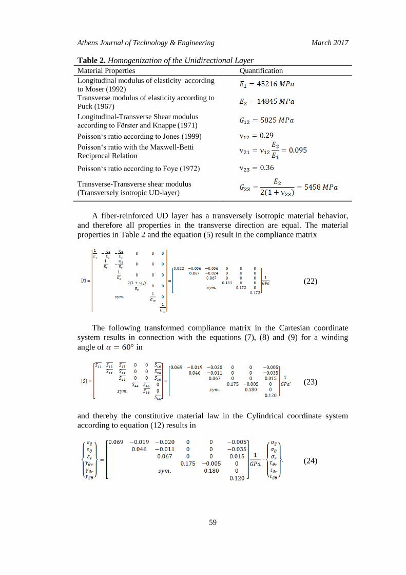
Table 2. Homogenization of the Unidirectional Layer
Material Properties Quantification
Longitudinal modulus of elasticity according
to Moser (1992)
Transverse modulus of elasticity according to
Puck (1967)
Longitudinal-Transverse Shear modulus
according to Förster and Knappe (1971)
Poisson‘s ratio according to Jones (1999)
Poisson‘s ratio with the Maxwell-Betti
Reciprocal Relation
Poisson‘s ratio according to Foye (1972)
Transverse-Transverse shear modulus
(Transversely isotropic UD-layer)
A fiber-reinforced UD layer has a transversely isotropic material behavior,
and therefore all properties in the transverse direction are equal. The material
properties in Table 2 and the equation (5) result in the compliance matrix
(22)
The following transformed compliance matrix in the Cartesian coordinate
system results in connection with the equations (7), (8) and (9) for a winding
angle of in
(23)
and thereby the constitutive material law in the Cylindrical coordinate system
according to equation (12) results in
(24)

Vol. 4, No. 1 Siegl et al.: Transformation of the Mechanical Properties…
60
The permutation matrix in accordance with equation (17) and the given
stress tensor in the Cylindrical coordinate system by Lekhnitskii (1963) from
equation (13) follows the HOOKE's law (see equations (14) and (15))
(25)
The transformed redenominated compliance matrix in equation (25) under
the convention of Lekhnitskii (1963) can be used to calculate the mentioned
bending models.
Conclusions
With the presented method of calculation, it is possible to enter the correct
material laws for the bending models of composite tubes only with the knowledge
of the individual layer parameters. For this purpose, the transformed compliances
which are related to the stresses and strains must not be resorted separately from
Cartesian converted into Cylindrical coordinate system and reversed due to the
relationships by Lekhnitskii (1963). This step will automatically be transferred by
the introduced permutation matrix, which can be easily integrated for
programming the analytical bending models. Therefore, calculation errors due to
the inconsistent notation of the compliances are avoided and correct coordinate
systems are defined which have a technical and production-related connection to
fiber-reinforced plastic tubes. In comparison, Lekhnitskii (1963) refers its
Cartesian coordinate system for generally anisotropic materials and does not
consider the fiber orientation, which is according to its definition in the radial
direction in the tube cross-section and has for this reason no technical application.
Nevertheless, the relations of Lekhnitskii (1963) are necessary to use the bending
models and therefore the technically meaningful coordinate system definition and
transformation was presented in this publication, and the relationship for the
Lekhnitskiis’ (1963) definition was established with the permutation.
References
Altenbach, H., Altenbach, J. and Kissing, W. (2004). Mechanics of Composite Structural
Elements. Springer-Verlag, Berlin/Heidelberg. DOI= http://bit.ly/2de RybT.
Chouchaoui, C. S. and Ochoa, O. O. (1999). Similitude study for a laminated cylindrical
tube under tensile, bending, internal and external pressure. Part I: governing
equations. Composite Structures, 44 (April 1999), Elsevier Science Limited,
Kidlington/Oxford, 221-229. DOI= http://bit.ly/2d5Eg2S.
Derisi, B. (2008). Development of thermoplastic composite tubes for large deformation.
Doctoral Thesis. Concordia University, Montréal. URL: http://bit.ly/ 2cR9azA.

Athens Journal of Technology & Engineering March 2017
61
Derisi, B., Hoa, S. and Hojjati, M. (2012). Similitude study on bending stiffness and
behavior of composite tubes. Journal of Composite Materials, 46 (Oct. 2012), 2695-
2710. DOI= http://bit.ly/2cqnuZg.
Ehrenstein, G. W. (2006). Faserverbundkunststoffe: Werkstoffe – Verarbeitung – Eigenschaf-
ten [Composites: materials - processing – properties]. Carl Hanser Verlag, München/
Wien.
Ehrlich, I. (2004). Impactverhalten schwach gekrümmter Strukturen aus faserverstärkten
Kunststoffen [Impact behavior of slightly curved structures of fiber reinforced
plastics]. Doctoral Thesis. Universität der Bundeswehr München, München. URL:
http://d-nb.info/973886102/34.
Förster, R. and Knappe, W. (1971). Experimentelle und theoretische Untersuchungen zur
Rißbildungsgrenze an zweischichtigen Wickelrohren aus Glasfaser/Kunststoff unter
Innendruck (Experimental and theoretical investigations of the crack initiation limit
of two-layer winding tubes of glass fiber/plastic under internal pressure).
Kunststoffe, 61 (1971), 583-588.
Foye, R. L. (1972). The transverse poisson's ratio of composites. Journal of Composite
Materials, 6 (April 1972), 293-295. DOI= http://bit.ly/2cMcIzs.
Geuchy Ahmad, M. I. and Hoa, S. V. (2016). Flexural stiffness of thick walled composite
tubes Composite Structures, 149 (Aug. 2016), 125-133. DOI= http://bit.ly/2cR8OsJ.
Jolicoeur, C. and Cardou, A. (1994). Analytical Solution for Bending of Coaxial
Orthotropic Cylinders. Journal of Engineering Mechanics, 120 (Dec. 1994), 2556-
2574. DOI= http://bit.ly/2dmvzAk.
Jones, R. M. (1999). Mechanics of Composite Materials. Taylor & Francis Verlag,
Philadelphia, PA.
Lekhnitskii, S. G. (1963). Theory of elasticity of an anisotropic body. Holden-Day, San-
Francisco, CA.
Moser, K. (1992). Faser-Kunststoff-Verbund – Entwurfs- und Berechnungs-grundlagen
[Fiber-reinforced plastic - design and bases of calculation]. VDI-Verlag, Düsseldorf.
Puck, A. (1967). Zur Beanspruchung und Verformung von GFK-Mehrschichtverbunden-
Bauelementen. Teil 1. Grundlagen der Spannungs- und Verformungsanalyse [To
stress and deformation of FRP multilayer composites components. Part 1.
Fundamentals of stress and deformation analysis], Kunststoffe, 57 (April 1967), 284
-293.
Sarvestani, H. Y., Hoa, S. V. and Hojjati, M. (2016). Stress analysis of thick orthotropic
cantilever tubes under transverse loading. Advanced Composite Materials, published
online (June 2016). DOI= http://bit.ly/2dfObGs.
Schmidt, K. and Trenkler, G. (2015). Einführung in die Moderne Matrix-Algebra – Mit
Anwendungen in der Statistik [Introduction to Modern matrix algebra - with
applications in statistics]. Springer Verlag, Berlin/Heidelberg. DOI= http://dx.doi.
org/10.1007/978-3-662-46773-2.
Schober, K.-U. (2008). Untersuchungen zum Tragverhalten hybrider Verbundkonstruk-
tionen aus Polymerbeton, faserverstärkten Kunststoffen und Holz [Investigations on
the behavior of hybrid composite structures made of polymer concrete, fiber-
reinforced plastics and wood]. Doctoral Thesis. Schriftenreihe des Instituts für
Konstruktiven Ingenieurbau Bauhaus-Universität Weimar, Weimar. URL= http://bit.
ly/2deRUQ3.
Schürmann, H. (2007). Konstruieren mit Faser-Kunststoff-Verbunden [Engineering with
fiber-reinforced composites]. Springer-Verlag, Berlin/Heidelberg.
DOI= http://dx.doi.org/10.1007/978-3-540-72190-1.

Vol. 4, No. 1 Siegl et al.: Transformation of the Mechanical Properties…
62
Shadmehri, F. (2012). Buckling of laminated composite conical shells: theory and
experiment. Doctoral Thesis. Concordia University, Montréal. URL= http://bit.ly/2c
Maxw7.
Shadmehri, F., Derisi, B. and Hoa, S. V. (2011). On bending stiffness of composite tubes.
Composite Structures, 93 (Aug. 2011), Elsevier Science Limited, Kidlington/Oxford,
2173-2179. DOI= http://bit.ly/2cWg97P.
Tarn, J.-Q., Wang, Y.-M. (2001). Laminated composite tubes under extension, torsion,
bending, shearing and pressuring: a state space approach. International Journal of
Solids and Structures, 38 (Dec. 2001), 9053-9075. DOI= http://bit.ly/2d5mu10.
Voigt, W. (1966). Lehrbuch der Kristallphysik [Textbook of crystal physics]. Springer-
Verlag, Berlin/Heidelberg. DOI= http://dx.doi.org/10.1007/978-3-663-15884-4.