Transformation of an Aviation Turboshaft Engine Into a ...
7
1 Copyright © 2014 by ASME TRANSFORMATION OF AN AVIATION TURBOSHAFT ENGINE INTO A EXPERIMENTAL JET ENGINE FOR LABORATORY TESTING UNSTABLE RADIAL COMPRESSOR WORK Marián Hocko Technical University of Košice Department of Aviation engineering Rampová 7, Košice, 041 21, Slovakia mail:[email protected] Jiri Polansky University of West Bohemia New Technologies Research Centre Univerzitní 8, Pilsen, 306 14, Czech Republic mail:[email protected] ABSTRACT The article deals with the use of a small aviation turboshaft engine for laboratory purposes. This study describes its transformation into an experimental device for research and education. Various constructional, technological and controlling modifications and settings of the gas turbine test stand were carried out and tested on a stationary configuration. The stationary system can be used as a small backup power generator or as a drive unit for a compressor, pump, etc. New control systems, electronic elements and methods of measuring rotations, pressure and temperature are tested for educational and research purposes. The study includes a schematic description of modelling measurements and subsequent numerical evaluation of the thermodynamic characteristics of the cycle in an experimental gas turbine. The laboratory device presented here is, thanks to technological, material and thermodynamic research, suitable for educating and testing the knowledge of future aviation and mechanical engineers. The content of the article is a description of the use of transformed small turboshaft engine into small jet engine by means of experimental testing of unstable work of the radial compressor under laboratory conditions. INTRODUCTION Unstable work (surge) of compressors is a dangerous phenomenon that occurs in a particular mode of compressors of aviation turbo compressor engine (ATCE) and also gas turbine (GT) that are used in vehicles and stationary applications. That is manifested by sudden changes in pressure and speed of the airflow at the outlet of the compressor and by characteristic sound effects that give rise to intense vibrations of the rotor blades and by changes of the of air flow characteristics in other parts of both ATCE and GT. The consequences of unstable work of the compressor are associated with cessation of activities of ATCE and GT, or their destruction because of mechanical damage of the compressor blades or destruction (burning) of the gas turbine blades. Therefore, the formation of unstable work of the compressor is inadmissible and much attention is devoted to prevention of its starting in ATCE and GT. Carrying out the research in unstable work of ATCE and GT compressors in a real operational context is associated with potential security risks and significant economic costs due to damage or destruction of expensive engines. Relevant results can be achieved without the mentioned risks under the laboratory conditions using the experimental small turbojet engine “MPM – 20” that was created by transforming the turbine trigger “TS – 20” into a small single jet engine. In experiments conducted at the Department of Aviation Engineering at the Faculty of Aeronautics, Technical University of Kosice, artificially induced unstable work of a centrifugal compressor, virtually confirmed the hypotheses and the relevant consequences for particular parts of the engine [1]. LAUNCH MECHANISM OF UNSTABLE COMPRESSOR WORK Unstable work of the ATCE compressor is a phenomenon that occurs when a particular mode of work of the compressor is manifested by severe periodic changes in theair flow rate Q A , the output air pressure from compressor p 2 ,absolute air speed cand sometimes back-flow of air from the compressor to the input ATCE device. Concomitants of unstable work of the ATCE compressor are: - pulsation of pressure p 2 (Fig. 1) and air velocity c 2 at the outlet of the compressor, - a reduction of the mean pressure at the outlet of the axial compressor p 2, m. - characteristic sound effects, - engine vibration, - vibration of compressor rotor blades. The formation of unstable compressor work during the operation of ATCE or ST can occur for various reasons, for exampleas a consequence of: - unstable work of input ATCE or GT device, - failures of an engine control system (accelerator machine, high-pressure pump, etc.), - sucking an object (birds, ice, etc.), - sudden changes in temperature conditions at the inlet to the Proceedings of the ASME 2014 International Mechanical Engineering Congress and Exposition IMECE2014 November 14-20, 2014, Montreal, Quebec, Canada IMECE2014-37298
Transcript of Transformation of an Aviation Turboshaft Engine Into a ...

1 Copyright © 2014 by ASME
TRANSFORMATION OF AN AVIATION TURBOSHAFT ENGINE INTO A EXPERIMENTAL JET ENGINE FOR LABORATORY TESTING UNSTABLE RADIAL COMPRESSOR WORK
Marián Hocko Technical University of Košice
Department of Aviation engineering Rampová 7, Košice, 041 21, Slovakia
mail:[email protected]
Jiri Polansky University of West Bohemia
New Technologies Research Centre Univerzitní 8, Pilsen, 306 14, Czech Republic
mail:[email protected] ABSTRACT
The article deals with the use of a small aviation turboshaft engine for laboratory purposes. This study describes its transformation into an experimental device for research and education. Various constructional, technological and controlling modifications and settings of the gas turbine test stand were carried out and tested on a stationary configuration. The stationary system can be used as a small backup power generator or as a drive unit for a compressor, pump, etc. New control systems, electronic elements and methods of measuring rotations, pressure and temperature are tested for educational and research purposes. The study includes a schematic description of modelling measurements and subsequent numerical evaluation of the thermodynamic characteristics of the cycle in an experimental gas turbine. The laboratory device presented here is, thanks to technological, material and thermodynamic research, suitable for educating and testing the knowledge of future aviation and mechanical engineers.
The content of the article is a description of the use of transformed small turboshaft engine into small jet engine by means of experimental testing of unstable work of the radial compressor under laboratory conditions.
INTRODUCTION
Unstable work (surge) of compressors is a dangerous phenomenon that occurs in a particular mode of compressors of aviation turbo compressor engine (ATCE) and also gas turbine (GT) that are used in vehicles and stationary applications. That is manifested by sudden changes in pressure and speed of the airflow at the outlet of the compressor and by characteristic sound effects that give rise to intense vibrations of the rotor blades and by changes of the of air flow characteristics in other parts of both ATCE and GT. The consequences of unstable work of the compressor are associated with cessation of activities of ATCE and GT, or their destruction because of mechanical damage of the compressor blades or destruction (burning) of the gas turbine blades. Therefore, the formation of unstable work of the compressor is inadmissible and much attention is devoted to prevention of its starting in ATCE and GT.
Carrying out the research in unstable work of ATCE and GT compressors in a real operational context is associated with potential security risks and significant economic costs due to damage or destruction of expensive engines. Relevant results can be achieved without the mentioned risks under the laboratory conditions using the experimental small turbojet engine “MPM – 20” that was created by transforming the turbine trigger “TS – 20” into a small single jet engine. In experiments conducted at the Department of Aviation Engineering at the Faculty of Aeronautics, Technical University of Kosice, artificially induced unstable work of a centrifugal compressor, virtually confirmed the hypotheses and the relevant consequences for particular parts of the engine [1].
LAUNCH MECHANISM OF UNSTABLE COMPRESSOR WORK
Unstable work of the ATCE compressor is a phenomenon that occurs when a particular mode of work of the compressor is manifested by severe periodic changes in theair flow rate QA, the output air pressure from compressor p2,absolute air speed cand sometimes back-flow of air from the compressor to the input ATCE device.
Concomitants of unstable work of the ATCE compressor are: - pulsation of pressure p2 (Fig. 1) and air velocity c2 at the outlet of the compressor, - a reduction of the mean pressure at the outlet of the axial compressor
p2, m. - characteristic sound effects, - engine vibration, - vibration of compressor rotor blades.
The formation of unstable compressor work during the operation of ATCE or ST can occur for various reasons, for exampleas a consequence of: - unstable work of input ATCE or GT device, - failures of an engine control system (accelerator machine, high-pressure pump, etc.), - sucking an object (birds, ice, etc.), - sudden changes in temperature conditions at the inlet to the
Proceedings of the ASME 2014 International Mechanical Engineering Congress and Exposition IMECE2014
November 14-20, 2014, Montreal, Quebec, Canada
IMECE2014-37298

2 Copyright © 2014 by ASME
engine (while passing over the fire, active volcano or suck- ing the off-gasses of another aircraft or launched missiles, etc.),
- sudden changes in active areas of the input device of the en- gine when aircraft is maneuvering,
- changes in air quality, for example in sucking volcanic ash when flying in the volcanic cloud and the like.
The consequence of unstable work of the ATCE or GT compressors can be: - an irregular operation of the engine, - a reduction in thrust (power) owing to reduced flowing amount of
air through the engine, - distortion of the normal steady burning of fuel-air mixture in the
main combustion chamber of ATCE, - the sharp increase in gas total temperature in front of the gas turbine
ATCET T3t, - increase of the vibration level of the whole ATCE, - possibility of breakage of the ATCE compressor rotor blades because
of vibration.
Fig. 1: Recorded parameter changes as the compressor is in surging [2]
1- course of changes in output static pressure p2, 2- course of changes in air flow QA through the compressor, 3- change of the active cross-section flow SACS through the comp.
Regarding the accompanying phenomena, which may lead to an interruption of the engine, its damage, or destruction of unstable work of the compressor, is admissible [5].
The entire process of creating the unstable work of the ATCE compressor is rather complicated. The physical principle to form unstable compressor work is based on tearing stream lines of airflow at the run around an individual compressor blade when major departure from the calculation mode of operation of the compressor, resulting in a sudden change in the air supply and pressure conditions at the inlet of the compressor ATCE.
LAUNCH OF UNSTABLE WORK OF AN AXIAL COMPRESSOR
In operation, the axial compressor in a computing mode corresponds to he air flow rate QA = QA, cal. of the rotor speed n and the peripheral speed of the rotor u1 at the absolute inlet air velocity c1 specifies the initial relative air speed at the rotor blade inlet w1, which flows in the direction of a tangent towards the central curve profile of a rotor blade to in between rotor blade channel. The outlet absolute velocity of the air from the compressor rotor blade c2 enters in between a rotor blade channel in the direction of a tangent towards the curve profile of a central stator vane. The airflow through the axial compressor stage is smooth, with out creating turbulence. The axial compressor is stable (Fig. 2a).
Fig. 2: The airflow character of an axial compressor stage
In reducing the rate of airflow QA< QA, cal. and particular engine speed n, the circuit rotor speed u will create, with reduced absolute speed c1, the resulting relative speed w1 the direction of which will deflect from the tangent to the medium curve of a rotor blade profile. This disrupts the smooth rotor blade and on their backs tearing off stream lines will occur and laminar flow to turbulent flow will be converted and spread farther to the stator vanes and other stages of the axial compressor. The roiled air flow in an axial compressor reduces smooth air flow farther into the main ATCE combustion chamber; it will result in backward flow of air back towards the ATCE input device. So the back flow of air in the space in front of the main combustion chamber sharply reduces air pressure and the air starts to move away from the input device to the main ATCE combustion chamber. The unstable air flow (surge) through the ATCE axial compressor results in an abrupt change in the composition of the fuel-air mixture in the main combustion chamber which causes a significant increase in the overall total temperature of the gas in front of the gas turbine TTt (sparingly rich mixture of fuel and air) and vibration of the rotor blades of the axial compressor with the possibility of their damage due to fatigue fracture (Fig. 2b).
With an increase in the rate of airflow QA > QA, cal., and the particular rotor speed n the circuit rotor speed u will create, with the increased absolute speed c1, a resulting input relative velocity of the air at the entrance to the rotor blades w1 the direction of which will deviate from the direction of the tangent to the profile middle curve of the rotor blade. This will cause hindering the smooth laminar airflow in the riverbed of rotor blades. The turbulent flow in the riverbed of blades will decline and there will be no farther spread of the break away streamlines into other stages of the axial compressor. Therefore, in this case there will be no formation of unstable work of the ATCE axial compressor (Fig. 2c). LAUNCH OF USTABLE WORK OF A RADIAL COMPRESSOR
Unstable work of the ATCE radial compressor results from tearing of the air flow to the impeller blades and the vanes of the diffuser at larger angle of attack changes in the incoming air, which may be caused by changing of the air flow rate, or by changing the rotor speed of the compressor.
Fig. 3: Stable air flow of radial compressor blades

3 Copyright © 2014 by ASME
Fig. 4: Unstable air flow of radial compressor blades
The formation of unstable work of the ATCE centrifugal compressor at higher values of calculated speed n c, such as computing speed mode np, cal..
[ ]1.min288. −=It
c Tnn
[ ]12
.min.
211.
288. −
⎟⎠
⎞⎜⎝
⎛ −+
=
II
c
MTnn
κ
(1)
Where:
nc - converted speed [min-1], n - measured speed of rotation [min-1], TIc - the total air temperature at the inlet to the radial compressor [K], TI - static air temperature at the inlet to the radial compressor [K], M - Mach flight number [1].
The equation (1) shows that the calculated speed will increase at low static air temperature TI and low speed expressed in the figure MI, corresponding to activities of ATCE in climbing to a great height.
If the air flow rate through a radial compressor equals to the computational rate of air flow QA = QA, cal., the air flow of radial compressor blades and diffuser vanes is smooth, the unstable work of a radial compressor will not occur. The radial compressor will work stably (Fig. 3).
If the air flow rate through a radial compressor is greater than the calculated air flow rate QA > QA, cal. tearing off the air flow in the riverbed of a radial compressor blades will occur. As the tearing area of the air flow is relatively small, it does not spread. On the diffuser vanes the air flow is tearing off on the back of the blades. Air particles tend to move along the curves that are close to the logarithmic spirals. Roiling of the air flow reduces the efficiency of radial compressor, but the air stream flows through the radial compressor but unstable work of the compressor usually does not occur (Fig. 5).
Fig. 5: Tearing off the air stream lines on the back of diffuser vanes at QA > QA, cal..
In reducing the rate of air flow through a radial compressor below
the calculated amount of air QA< QA, cal., tearing off the air flow at the
back of the impeller blades (Fig. 4) and diffuser vanes will occur (Fig. 6). The detached air stream loses velocity and reduces the flow area. So the decrease in the kinetic energy tends to increase the static pressure, which leads to the return flow and the consequent restoration of steady flow (surge). This processes again repeated at short intervals [2, 3].
Fig. 6: Tearing off the air stream lines on the back of diffuser vanes at
QA < QA, cal.
EXPERIMENTAL VERIFICATION OF UNSTABLE WORK OF A RADIAL COMPRESSOR
As mentioned in the previous part of this article, one of the
causes of ATCE compressor unstable work is a change of air flow through the engine inlet device as a result of throttle down from variety of reasons. In theory, this process is explained in the particular (constant speed) mode by shifting an operating point along the linen = const. in the characteristics of a radial compressor to the left border of the unstable work [4]. In sufficient reduction in air flow rate QA via the in put device the operating point of the engine exceeds a thre shold of unstable work and gets in unstable work of the radial compressor (surge area) (Fig. 7).
Fig. 7: Calculated characteristics of a radial compressor of an
experimental small turbojet engine “MPM-20” [4] Where: πCt – the total degree of air compression on the compressor [1] ηCt – the total compression efficiency [1]
For practical testing of theoretical hypotheses, the Laboratory for
small turbojets at the Department of Aviation Engineering, Technical University of Kosice has been used, in which the experimental small single jet engine is available, it was created by conversion of the turbine trigger “TS-20” [7].
“MPM-20” is a small single jet engine with a diagonal entry system, single-stage centrifugal compressor, an associated combustion chamber, single stage uncooled gas turbine and the fixed exhaust nozzle.

4 Copyright © 2014 by ASME
Fig. 8: View of the “MPM-20” at the Laboratory of small jet engines
Fig. 9: Section of a small turbojet engine “MPM-20” [7]
THROTTLING OF AIR FLOW IN THE INLET SYSTEM The practical experimental verification of the impact of throttling
the flow of air in the intake device of “MPM – 20” on an unstable work of a radial compressor, the method for gradual increasing the density of nets has been implemented; each was placed on the input system of the engine.
The processed linear mathematical model of “MPM-20” is based on the theory of small changes in [8], described in [1, 10] for the sub-critical conditions of flow in the outlet nozzle, defines the conditions of change in the intake device reflected by changes of all parameters of the working process of single jet ATCE. For practical validation of this theory four sets of experimental measurements were prepared and aimed at gradually throttling the air flow through the input device “MPM - 20th”. The measured parameter values for individual experimental measurements are compared with the values obtained in the calibration measurement and the theoretical calculation based on the theory of small changes. Gradually these experimental measurements were realized: 1. Air flow through the input device of “MPM – 20” without the input sieve. 2. Air flow through the input device of “MPM – 20” with the sieve mesh size of 1.5 x 1.5 mm. 3. Air flow through the inlet system of “MPM – 20” with a double sieve (a sieve with a mesh size of 1.5 x 1.5 mm and a sieve with mesh of 2.5 x 2.5 mm). 4. Air flow through the inlet device of “MPM – 20” with a TV viewings creen with openings with a diameter of 0.4 mm.
The change in the independent variable (failures) was calculated according to the formula:
[ ]%100.0
0⎥⎦
⎤⎢⎣
⎡ −=
XXXX si
siδ (2)
Where: δXsi – change in the independent variable,
Xsi – a value parameter in a simulated malfunction, X0 – an original value of the independent variable. The change inthe dependent variable value was calculated according to the equation:
[ ]%100.0
0⎥⎦
⎤⎢⎣
⎡ −=
YYYY si
siδ (3)
Where: δYsi – a change of the dependent variable, Ysi– a value parameter in the simulated malfunction, Y0 – an original value of the dependent variable. THE AIR FLOW THROUGH THE INLET DEVICE OF “MPM-20” WITHOUT AN INLET SIEVE
For the conditions of the first experiment the original in put protective sieve was removed from the entrance system of “MPM-20”.
Before carrying out the planned experiments, the “MPM-20” was set according to the technical documentation for a calculation scheme [9]. Subsequently 10 measurements of calibration parameters were performed. The mean value of the measured parameters obtained by the calibration measurement served as a bench mark for assessing changes in subsequent experimental measurements.
Fig. 10: Removing the protective sieve from “MPM-20”
A relatively high degree of agreement of measured and calculated thermodynamic parameters is apparent from the results of the calibration measurements processed in “MPM – 20” and its comparison with the results of thermodynamic calculation of heat circulation of “MPM – 20”. Minor deviations between measured and calculated values of the thermodynamic parameters are caused by irregularities occurring in the measurement because of the location of sensors in other positions as suggested in the theoretical calculation.
PARAMETER pH TH ACTIVITY PERIOD p2,C
´ p2t,C´ p2t
UNIT Pa K Sec. Pa Pa Pa MEASURED
VALUE 99885,82 290,65 50,8 180787,9 392652,7 351971,5
COUNTED VALUE 101325,2 288 50 181600,13 398549,2 392321,5
PARAMETER p3 p4 T2t´ T2t T3t T4t
UNIT Pa Pa K K K K MEASURED
VALUE 351326,2 154655,78 458,55 460,25 1170,35 1043,45
COUNTED VALUE 392321,5 162812,95 462,35 462,35 1168,15 1013,27
PARAMETER Qfuel Gfuel ch FT QA cm
UNIT cm3/CYKLUS kg/CYKLUS kg.h-1 N kg.s-1 kg.h-1.N-1
MEASURED VALUE 1362 1,05572 74,87 - - -
COUNTED VALUE - - - 698,09 1,2 0,1311
Tab. 1: Comparison of calculated and measured values of the parameters in the calibration measurements of “MPM – 20”

5 Copyright © 2014 by ASME
Where: pH – atmospheric pressure [Pa], TH – atmospheric temperature [K], p2,C´ – static presurebehind compressor impeller [Pa], p2t,C´– total presure behind compressor impeller [Pa], p3 – static presure before turbine [Pa], p4 – static presure behind compressor impeller [Pa], T2t´–total temperature behind compressor impeller [K], T2t – total temperature behind compressor [K], T3t – total temperature before turbine [K], T4t – total temperature behind turbine [K], Qfuel – fuel flow [kg.s-1], Gfuel – weight of fuel consumption per cyckle [kg. cycle-1], ch – fuel consumption per hour [kg. h-1], FT – thrust [N], QA –air flow [kg.s-1], cm – specific fuel consumption [kg.N-1.h-1].
In the first experiment (Fig. 10) 10 measurements were performed and the same parameters as for the calibration measurements “MPM – 20” in the original configuration (with a protective sieve) were measured and evaluated. The mode of “MPM – 20” operations was set to values that correspond to the calibration measurement (computing) mode; external conditions (pH, TH) have not changed.
As is apparent from the data given in [1], that compares the measured values of the parameters in the experimental measurements without the input sieve and the calibration measurements, the differences in individual parameters are minimum and range from -5.4 % (static gas pressure behind the gas turbine p4) to +2.9 % (total gas temperature behind the gas turbine T4t). Most of the other observed parameters have hardly changed even though the flow area of the inlet to the “MPM – 20”, after the removal of the inlet sieve, grew by 35 % (a total area of the inlet sieve with a wire sieve of a mesh size of 2.5 x 2.5 mm and wire thickness of 0.6 mm wire is 0.078593 m2).
The results obtained by direct measurement of “MPM -20” without input sieve confirm that the choice of the wire diameter and the mesh size has been optimized by the engine manufacturer so that the sieve provides the protection from sucking strange objects with a minimum influence on the parameters of “MPM – 20”. Based on the measured parameters, the calculation of thrust FT and of specific fuel consumption cm were performed.
THE AIR FLOW THROUGH THE INLET DEVICE OF “MPM-20” WITH THE SOFT INLET SIEVE
In the second experimental measurement, the air flow through the soft sieve of an input device was throttled, which was deployed on the input device of “MPM-20”. The total area of the inlet sieve is 0,078593 m2. When using a wire sieve with a mesh size of 1.5 x 1.5 mm and at hickness of 0.3 mm ire, the occupied area of the input wire sieve is 34.984% of the total area of the input device.
The measured values of parameters of “MPM-20”, described in [1], are very close to the measured values in calibration measurements with the original sieve.
AIR FLOW THROUGH THE INLET DEVICE OF MPM-20 WITH A DOUBLE INPUT SIEVE
Third experimental measurements were carried out at throttling off low with the dual sieve (Fig. 11). To the original input device with an original protective sieve of “MPM-20” a soft sieve with the mesh size of 1.5x1.5 mm and a thickness of 0.3 mm wire was deployed, thus reducing the flow area by 58 %. On the basis of the reduction in the flow area of the inlet system the measured thermodynamic parameters
have been changed, resulting in a change of the engine-dependent parameters. The total degree of gas expansion significantly changed on the gas turbine πTt (about 19.194%) and the total temperature of gas behind the gas turbine T4t (by 4,475%).
Fig. 11: Dual sieve of “MPM-20” AIR FLOW THROUGH THE INLET DEVICE OF “MPM-20” WITH THE SOFEST INLET SIEVE
The recent experimental measurement was carried out with strong throttling of flow through the input device, using aperforated metal plate with round holes 0.4 mm (a metal plate was originally used as a color TV viewing screen) (Fig. 12, 13). The perforated plate was placed on the original sieve of an input device, thereby allowing are duction by 83% in the flow area of the inlet system of “MPM-20”. This reducing of the flow area of the engine inlet device was substantial degradation of measured parameters compared to measured parameters at the input device without the inlet sieve (Δp2t = -48 978,8 Pa, Δp3 = 24198,5 Pa, Δp4 = -24957,82 Pa, T2t = -11,6 K, ΔT3t = -92,4 K, ΔT4t = -177,5 K, ch = -4,3465 kg.h-1, ΔπTt = 0,6, ΔπCt = -0,509 a ΔπENt = -0,257. Where: πCt – the total degree of air compression on the compressor [1], πTt – the total degree of gas expansion on the gas turbine πTt [1], πENt – the total degree of gas expansion on the exhaust nozzle [1].
Fig. 12: Perforated plate attached to the original inlet device of “MPM-20”
6 Copyright © 2014 by ASME
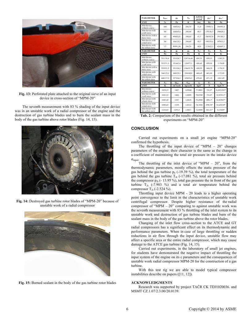
Fig. 13: Perforated plate attached to the original sieve of an input device in cross-section of “MPM-20”
The seventh measurement with 83 % shading of the input device
was in an unstable work of a radial compressor of the engine and the destruction of gas turbine blades and to burn the sealant mass in the body of the gas turbine above rotor blades (Fig. 14, 15).
Fig. 14: Destroyed gas turbine rotor blades of “MPM-20” because of
unstable work of a radial compressor
Fig. 15: Burned sealant in the body of the gas turbine rotor blades
PARAMETER Sinlet. pH TH Activity period p2,C´ p2t,C´
UNIT % Pa K Sec. Pa Pa Inlet device without a sieve 100 100525,3 288,75 51,0 178967,1 388941,8
Inlet device with a soft sieve 80 100365,6 290,95 49,7 179136,7 390028,1
Inlet device with a basic sieve 65 99885,82 290,65 51,7 180787,9 391185,7
Inlet device with a dual sieve 58 100125,3 290,65 49,7 198319,4 397633,7
Inlet device with the softest sieve 17 99991,98 290,29 50,0 213852,3 428407,3
PARAMETER p2t p3 p4 T2t´ T2t T3t
UNIT Pa Pa Pa K K K
Inlet device without a sieve 351178,4 351524,7 128716,48 458,35 459,55 1169,25
Inlet device with a soft sieve 351571,5 351462,6 128977,1 458,45 459,95 1170,05
Inlet device with a basic sieve 351971,5 351326,2 154655,78 458,55 460,25 1170,35
Inlet device with a dual sieve 366122,2 340125,3 154192,9 460,65 461,95 1172,95
Inlet device with the softest sieve 400157,2 327326,2 153674,3 470,01 471,15 1261,65
PARAMETER T4t Qfuel Gpal. ch FT cm
UNIT K cm3/cycle kg/cycle kg.h-1 N kg.h-1N1
Inlet device without a sieve 1039,15 1407 1,09045 77,0065 732,5* 0,1051283*
Inlet device with a soft sieve 1041,15 1405 1,0889 78,8700 731,6* 0,107811*
Inlet device with a basic sieve 1043,45 1397 1,0819 75,2900 698,1* 0,107847*
Inlet device with a dual sieve 1085,65 1330 1,0312 74,7434 598,74* 0,125334*
Inlet device with the softest sieve 1216,65 1293,3 1,0027 72,6600 541,11* 0,13428*
Tab. 2: Comparison of the results obtained in the different experiments on “MPM-20”
CONCLUSION
Carried out experiments on a small jet engine “MPM-20” confirmed the hypothesis.
The throttling of the input device of “MPM – 20” changes parameters of the engine; their character is the same as the change in a coefficient of maintaining the total air pressure in the intake device σinput.
The throttling of the inlet device of “MPM – 20”, from the thermodynamic parameters, mostly effects the static pressure of the gas behind the gas turbine p4 (-19.39 %), the total temperature of the gas behind the gas turbine T4t (-17.081 %), total air pressure behind the compressor p2t (- 13.95 %), total gas pressure the in front of the gas turbine T3t (-7.903 %) and a total air temperature behind the compressor T2t (-2.524 %).
Throttling input device MPM - 20 leads to a higher operating point convergence to the limit in the characteristics of unstable work centrifugal compressor. Despite higher resistance of the radial compressor of “MPM – 20” comparing to against unstable work was the seventh measurement with 83 % throttling of the inlet system to its unstable work and destruction of gas turbine blades and burn of the sealant mass in the body of the gas turbine above the rotor blades.
Changing of the inlet flow cross-section to the ATCE and GT radial compressors has a significant effect on its thermodynamic and performance parameters. When in case of large throttling or sudden reductions in air flow through the input device, unstable flow may affect a specific area or the entire radial compressor, which may cause damage to the ATCE gas turbine (Fig. 14, 15).
Carried out experiments, in the laboratory of small jet engines, for students have demonstrated the negative impact of throttling the input system of the engine on its c parameters and the consequences of unstable work radial compressor MPM-20 for the construction of a gas turbine.
With this test rig we are able to model typical compressor instabilities describe on papers ([11, 12]).
ACKNOWLEDGMENTS
Research was supported by project TAČR CK TE01020036. and MSMT CZ.1.07/2.3.00/20.0139.

7 Copyright © 2014 by ASME
REFERENCES [1] Hocko M., 2003, „Assessment of the ATCE State Based on Changes in Thermodynamic Parameters“, thesis, pp. 338 [2] Ruzek, J., 1979, „Theory of Aircraft Engines, Part I (Compressors, Turbines and a Combustion Chamber)“, University textbook VA AZ Brno, pp. 373 [3] Ott, A., 1983, „Fundamentals of the Theory and Design of Air Vane Engines, Part I“, University Textbook, Military Academy of Aviation, Kosice, pp.140 [4] Med, S.: „Diagnosis of JE - TS -20 in Laboratory Conditions K – 316“, master's thesis, Department of Aircraft, Military academy in Brno [5] Cumpsty, NA, 1989, „Compressor aerodynamics”, Department of Engineering University of Cambridge, pp. 687 [6] Hocko, M.,Gaspar,R.,2013, „Impact of rapid thermal fluctuations of the airflow into engine inlet to the gas dynamics stability of the turbojet engine“, 12th conference Power System Engineering, Thermodynamics & Fluid Flow, Pilsen. pp. 8
[7] Hocko M., 2003,„The small jet engine MPM – 20“, VLA Kosice [8] Черкез, А., Я., 1975, „Инжинерные расчеты газотурбиных двигателей методом малых одклонений“, Издательство Машиностроиение, pp. 379 [9] „The operation and maintenance of the engine AL - 7F - 1 , Book 2 , Book 3,Let -21 -20/2,Let -21 -20/ 3“, Praha 1965 [10] Főző , L., Andoga, R., Madarász, L., 2010 , „Mathematical model of asmall Turbojet Engine MPM – 20“. In: Studies in Computational Intelligence.Vol . 313, p. 313-322 [11] Polansky J., Kalmar L., Gaspar R.: Aerodynamic performance prediction of centrifugal fan with forward curved blades, Journal of Thermal Science, Vol 22, NO 6, 2013 pp 517-521, ISSN: 1003-2169 , 2013 [12] Cyrus, V.; Polansky, J.: Numerical simulation of the origins of flow pulsations in cascades of the rear blade rows in a gas turbine axial compressor using low calorific fuel. ASME journal 2010, no. 132/3, p. 31012/1-11. ISSN: 0889-504X


![Donnelly Farnborough 2006 v4[1] PRINT - General Electric · PDF fileGE Aviation Scott C. Donnelly President & CEO ... 1997 CFM56-7 Turboshaft 1957 1964 2002 Next 1978 1988 1984 T58](https://static.fdocuments.net/doc/165x107/5a7acc3b7f8b9a49588b68b2/donnelly-farnborough-2006-v41-print-general-electric-aviation-scott-c-donnelly.jpg)