
Transferencia de calor y masa 4ed yunus cengel solucionario cap 08
97
PROPRIETARY MATERIAL . © 2011 The McGraw-Hill Companies, Inc. Limited distribution permitted only to teachers and educators for course preparation. If you are a student using this Manual, you are using it without permission. 8-1 Solutions Manual for Heat and Mass Transfer: Fundamentals & Applications Fourth Edition Yunus A. Cengel & Afshin J. Ghajar McGraw-Hill, 2011 Chapter 8 INTERNAL FORCED CONVECTION PROPRIETARY AND CONFIDENTIAL This Manual is the proprietary property of The McGraw-Hill Companies, Inc. (“McGraw-Hill”) and protected by copyright and other state and federal laws. By opening and using this Manual the user agrees to the following restrictions, and if the recipient does not agree to these restrictions, the Manual should be promptly returned unopened to McGraw-Hill: This Manual is being provided only to authorized professors and instructors for use in preparing for the classes using the affiliated textbook. No other use or distribution of this Manual is permitted. This Manual may not be sold and may not be distributed to or used by any student or other third party. No part of this Manual may be reproduced, displayed or distributed in any form or by any means, electronic or otherwise, without the prior written permission of McGraw-Hill.
-
Upload
franzyzko-marin -
Category
Engineering
-
view
2.315 -
download
312
Transcript of Transferencia de calor y masa 4ed yunus cengel solucionario cap 08

PROPRIETARY MATERIAL. © 2011 The McGraw-Hill Companies, Inc. Limited distribution permitted only to teachers and educators for course preparation. If you are a student using this Manual, you are using it without permission.
8-1
Solutions Manual for
Heat and Mass Transfer: Fundamentals & Applications Fourth Edition
Yunus A. Cengel & Afshin J. Ghajar McGraw-Hill, 2011
Chapter 8 INTERNAL FORCED CONVECTION
PROPRIETARY AND CONFIDENTIAL This Manual is the proprietary property of The McGraw-Hill Companies, Inc. (“McGraw-Hill”) and protected by copyright and other state and federal laws. By opening and using this Manual the user agrees to the following restrictions, and if the recipient does not agree to these restrictions, the Manual should be promptly returned unopened to McGraw-Hill: This Manual is being provided only to authorized professors and instructors for use in preparing for the classes using the affiliated textbook. No other use or distribution of this Manual is permitted. This Manual may not be sold and may not be distributed to or used by any student or other third party. No part of this Manual may be reproduced, displayed or distributed in any form or by any means, electronic or otherwise, without the prior written permission of McGraw-Hill.

PROPRIETARY MATERIAL. © 2011 The McGraw-Hill Companies, Inc. Limited distribution permitted only to teachers and educators for course preparation. If you are a student using this Manual, you are using it without permission.
8-2
General Flow Analysis
8-1C Engine oil requires a larger pump because of its much larger density.
8-2C The generally accepted value of the Reynolds number above which the flow in a smooth pipe is turbulent is 4000.
8-3C For flow through non-circular tubes, the Reynolds number as well as the Nusselt number and the friction factor are
based on the hydraulic diameter Dh defined as pA
D ch
4= where Ac is the cross-sectional area of the tube and p is its
perimeter. The hydraulic diameter is defined such that it reduces to ordinary diameter D for circular tubes since
DD
DpA
D ch ===
ππ 4/44 2
.
8-4C The hydrodynamic and thermal entry lengths are given as DLh Re05.0= and Lt D= 0 05. Re Pr for laminar flow, and in turbulent flow. Noting that Pr >> 1 for oils, the thermal entry length is larger than the hydrodynamic
entry length in laminar flow. In turbulent, the hydrodynamic and thermal entry lengths are independent of Re or Pr numbers, and are comparable in magnitude.
DLL th 10≈≈
8-5C The friction factor is highest at the tube inlet where the thickness of the boundary layer is zero, and decreases gradually to the fully developed value. The same is true for turbulent flow.
8-6C In turbulent flow, the tubes with rough surfaces have much higher friction factors than the tubes with smooth surfaces. In the case of laminar flow, the effect of surface roughness on the friction factor is negligible.
8-7C The friction factor f remains constant along the flow direction in the fully developed region in both laminar and turbulent flow.
8-8C The fluid viscosity is responsible for the development of the velocity boundary layer. For the idealized inviscid fluids (fluids with zero viscosity), there will be no velocity boundary layer.

PROPRIETARY MATERIAL. © 2011 The McGraw-Hill Companies, Inc. Limited distribution permitted only to teachers and educators for course preparation. If you are a student using this Manual, you are using it without permission.
8-3
8-9C The number of transfer units NTU is a measure of the heat transfer area and effectiveness of a heat transfer system. A small value of NTU (NTU < 5) indicates more opportunities for heat transfer whereas a large NTU value (NTU >5) indicates that heat transfer will not increase no matter how much we extend the length of the tube.
8-10C The hydrodynamic and thermal entry lengths are given as DLh Re05.0= and for laminar flow, and in turbulent flow. Noting that Pr << 1 for liquid metals, the thermal entry length is smaller than the hydrodynamic entry length in laminar flow. In turbulent, the hydrodynamic and thermal entry lengths are independent of Re or Pr numbers, and are comparable in magnitude.
DLt PrRe05.0=DLL th 10≈≈
8-11C In fluid flow, it is convenient to work with an average or mean velocity Vavg and an average or mean temperature Tm which remain constant in incompressible flow when the cross-sectional area of the tube is constant. The Vavg and Tm represent the velocity and temperature, respectively, at a cross section if all the particles were at the same velocity and temperature.
8-12C The logarithmic mean temperature difference lnT∆ is an exact representation of the average temperature difference between the fluid and the surface for the entire tube. It truly reflects the exponential decay of the local temperature difference. The error in using the arithmetic mean temperature increases to undesirable levels when differs from by great amounts. Therefore we should always use the logarithmic mean temperature.
eT∆ iT∆
8-13C The region of flow over which the thermal boundary layer develops and reaches the tube center is called the thermal entry region, and the length of this region is called the thermal entry length. The region in which the flow is both hydrodynamically (the velocity profile is fully developed and remains unchanged) and thermally (the dimensionless temperature profile remains unchanged) developed is called the fully developed region.
8-14C The heat flux will be higher near the inlet because the heat transfer coefficient is highest at the tube inlet where the thickness of thermal boundary layer is zero, and decreases gradually to the fully developed value.
8-15C The heat flux will be higher near the inlet because the heat transfer coefficient is highest at the tube inlet where the thickness of thermal boundary layer is zero, and decreases gradually to the fully developed value.
8-16C In the fully developed region of flow in a circular tube, the velocity profile will not change in the flow direction but the temperature profile may.
8-17C The region from the tube inlet to the point at which the boundary layer merges at the centerline is called the hydrodynamic entry region, and the length of this region is called hydrodynamic entry length. The entry length is much longer in laminar flow than it is in turbulent flow. But at very low Reynolds numbers, Lh is very small (Lh = 1.2D at Re = 20).

PROPRIETARY MATERIAL. © 2011 The McGraw-Hill Companies, Inc. Limited distribution permitted only to teachers and educators for course preparation. If you are a student using this Manual, you are using it without permission.
8-4
8-18C When the surface temperature of tube is constant, the appropriate temperature difference for use in the Newton's law of cooling is logarithmic mean temperature difference that can be expressed as
)/ln(lm
ie
ie
TTTT
T∆∆∆−∆
=∆
8-19 Air flows inside a duct and it is cooled by water outside. The exit temperature of air and the rate of heat transfer are to be determined.
Assumptions 1 Steady operating conditions exist. 2 The surface temperature of the duct is constant. 3 The thermal resistance of the duct is negligible.
10°C
D = 18 cm
L = 12 m
Properties The properties of air at the anticipated average temperature of 30°C are (Table A-15) Air
50°C 7 m/s
CJ/kg. 1007kg/m 164.1 3
°==
pcρ
Analysis The mass flow rate of water is
kg/s 0.2073=m/s) (74
m) (0.18)kg/m 164.1(4
23
avg
2
avgππρρ =⎟
⎟⎠
⎞⎜⎜⎝
⎛== VDVAm c&
2m 6.786=m) m)(12 18.0(ππ == DLAs
The exit temperature of air is determined from
C 14.84 °=−−=−−=−
− )1007)(2073.0()786.6)(65( )/( )5010(10)( eeTTTT ps cmhA
isse&
The logarithmic mean temperature difference and the rate of heat transfer are
kW 7.34==°°=∆=
°=⎟⎠⎞
⎜⎝⎛
−−
−=
⎟⎟⎠
⎞⎜⎜⎝
⎛−−
−=∆
W7343)C65.16)(m 786.6)(C. W/m65(
C65.16
501084.1410ln
5084.14
ln
22lm
lm
ThAQ
TTTT
TTT
s
is
es
ie
&

PROPRIETARY MATERIAL. © 2011 The McGraw-Hill Companies, Inc. Limited distribution permitted only to teachers and educators for course preparation. If you are a student using this Manual, you are using it without permission.
8-5
8-20 Steam is condensed by cooling water flowing inside copper tubes. The average heat transfer coefficient and the number of tubes needed are to be determined.
Assumptions 1 Steady operating conditions exist. 2 The surface temperature of the pipe is constant. 3 The thermal resistance of the pipe is negligible.
Properties The properties of water at the average temperature of (10+24)/2=17°C are (Table A-9) Steam, 30°C
24°C D = 1.2 cm
L = 5 m
CJ/kg. 8.4183
kg/m 7.998 3
°==
pcρ
Water 10°C 4 m/s Also, the heat of vaporization of water at 30°C is
. kJ/kg 2431=fgh
Analysis The mass flow rate of water and the surface area are
kg/s 0.4518=m/s) (44
m) (0.012)kg/m 7.998(4
23
avg
2
avgππρρ =⎟
⎟⎠
⎞⎜⎜⎝
⎛== VDVAm c&
The rate of heat transfer for one tube is
W460,26)C1024)(CJ/kg. 8.4183)(kg/s 4518.0()( =°−°=−= iep TTcmQ &&
The logarithmic mean temperature difference and the surface area are
C63.11
10302430ln
1024
lnlm °=
⎟⎠⎞
⎜⎝⎛
−−
−=
⎟⎟⎠
⎞⎜⎜⎝
⎛−−
−=∆
is
es
ie
TTTT
TTT
2m 0.1885=m) m)(5 012.0(ππ == DLAs
The average heat transfer coefficient is determined from
C.kW/m 12.1 2 °=⎟⎠⎞
⎜⎝⎛
°=
∆=⎯→⎯∆=
W1000kW 1
)C63.11)(m 1885.0( W460,26
2lm
lm TAQhThAQ
ss
&&
The total rate of heat transfer is determined from
kW 65.364kJ/kg) 2431)(kg/s 15.0( === fgcondtotal hmQ &&
Then the number of tubes becomes
13.8=== W460,26 W650,364
N totaltube &
&

PROPRIETARY MATERIAL. © 2011 The McGraw-Hill Companies, Inc. Limited distribution permitted only to teachers and educators for course preparation. If you are a student using this Manual, you are using it without permission.
8-6
8-21 Steam is condensed by cooling water flowing inside copper tubes. The average heat transfer coefficient and the number of tubes needed are to be determined.
Assumptions 1 Steady operating conditions exist. 2 The surface temperature of the pipe is constant. 3 The thermal resistance of the pipe is negligible.
Properties The properties of water at the average temperature of (10+24)/2=17°C are (Table A-9) Steam, 30°C
24°C D = 1.2 cm
L = 5 m
CJ/kg. 8.4183
kg/m 7.998 3
°==
pcρ
Water 10°C 4 m/s
Also, the heat of vaporization of water at 30°C is . kJ/kg 2431=fgh
Analysis The mass flow rate of water is
kg/s 0.4518=m/s) (44
m) (0.012)kg/m 7.998(4
23
avg
2
avgππρρ =⎟
⎟⎠
⎞⎜⎜⎝
⎛== VDVAm c&
The rate of heat transfer for one tube is
W460,26)C1024)(CJ/kg. 8.4183)(kg/s 4518.0()( =°−°=−= iep TTcmQ &&
The logarithmic mean temperature difference and the surface area are
C63.11
10302430ln
1024
lnlm °=
⎟⎠⎞
⎜⎝⎛
−−
−=
⎟⎟⎠
⎞⎜⎜⎝
⎛−−
−=∆
is
es
ie
TTTT
TTT
2m 0.1885=m) m)(5 012.0(ππ == DLAs
The average heat transfer coefficient is determined from
C.kW/m 12.1 2 °=⎟⎠⎞
⎜⎝⎛
°=
∆=⎯→⎯∆=
W1000kW 1
)C63.11)(m 1885.0( W460,26
2lm
lm TAQhThAQ
ss
&&
The total rate of heat transfer is determined from
kW 6.1458kJ/kg) 2431)(kg/s 60.0( === fgcondtotal hmQ &&
Then the number of tubes becomes
55.1=== W460,26
W600,458,1Q
QN total
tube &
&

PROPRIETARY MATERIAL. © 2011 The McGraw-Hill Companies, Inc. Limited distribution permitted only to teachers and educators for course preparation. If you are a student using this Manual, you are using it without permission.
8-7
8-22 The average velocity and mean temperature are to be determined from the given velocity and temperature profiles.
Assumptions 1 Steady operating conditions exist. 2 Properties are constant.
Analysis The average velocity in a tube with a radius of R = D/2 is
drrruR
VR
)(2
0 2avg ∫=
m/s 0.025=⎥⎥⎦
⎤
⎢⎢⎣
⎡ −−=−= ∫
RR
RRr
RdrRrr
RV
0 2
222
2
0
22avg
)(0125.02 ])/(1[05.02
The mean temperature in a tube with a radius of R = D/2 is
drrrurTRV
TR
m )()(2
0 2avg
∫=
( ) K 420==
−+−−+=
−−+=
∫
∫
22
0
542322
0
2322
avg
1054
])/(30)/(80)/(400[])/(30)/(80400[4
])/(1][)/(30)/(80400[)05.0(2
RR
drRrrRrrRrrRrrRrrrR
drRrRrRrrRV
T
R
Rm
Discussion Note that the average velocity is half of the maximum velocity (velocity at the center of the tube) for the given profile. This suggests that the given velocity profile has a profile of a fully developed laminar flow or it is parabolic.

PROPRIETARY MATERIAL. © 2011 The McGraw-Hill Companies, Inc. Limited distribution permitted only to teachers and educators for course preparation. If you are a student using this Manual, you are using it without permission.
8-8
8-23 The mass flow rate and the surface heat flux are to be determined from the given velocity and temperature profiles.
Assumptions 1 Steady operating conditions exist. 2 Properties are constant.
Properties The density of 1 atm air at 20°C is ρ = 1.204 kg/m3 (Table A-15).
Analysis The average velocity in a tube with a radius of R = D/2 is
drrruR
VR
)(2
0 2avg ∫=
m/s10)(05.02 ])/(1[2.02
0 2
222
2
0
22avg .
RRr
RdrrRr
RV
RR
=⎥⎥⎦
⎤
⎢⎢⎣
⎡ −−=−= ∫
The mean temperature in a tube with a radius of R = D/2 is
drrrurTRV
TR
m )()(2
0 2avg
∫=
K 7295)93.73(4
])/(200)/(250[])/(200250[4
])/(1][)/(200250[)2.0(2
22
0
5232
0
232
avg
.RR
drRrrRrrRrrrR
drrRrRrRV
T
R
Rm
==
+−+=
−+=
∫
∫
The mass flow rate is
kg/s 106.05 4−×==== 4/)m 08.0()m/s 1.0)(kg/m 204.1(4/ 232avgavg ππρρ DVAVm c&
The surface heat flux is determined using
where )( mss TThq −=& K 450)/(200250)( 3 =+== RRrTT os
2kW/m 15.4=−⋅= K )7.295450)(K W/m100( 2sq&
Discussion Since Ts > Tm, this indicates that the air is being heated, thus a positive value for the surface heat flux.

PROPRIETARY MATERIAL. © 2011 The McGraw-Hill Companies, Inc. Limited distribution permitted only to teachers and educators for course preparation. If you are a student using this Manual, you are using it without permission.
8-9
8-24 Combustion gases passing through a tube are used to vaporize waste water. The tube length and the rate of evaporation of water are to be determined.
Assumptions 1 Steady operating conditions exist. 2 The surface temperature of the pipe is constant. 3 The thermal resistance of the pipe is negligible. 4 Air properties are to be used for exhaust gases.
Properties The properties of air at the average temperature of (250+150)/2=200°C are (Table A-15)
kJ/kg.K 287.0
CJ/kg. 1023
=
°=
R
c pTs=110°C
150°CExh. gases250°C 5 m/s
D = 5 cm
L
Also, the heat of vaporization of water at 1 atm or 100°C is (Table A-9). kJ/kg 2257=fgh
Analysis The density of air at the inlet and the mass flow rate of exhaust gases are
3kg/m 7662.0K) 273250(kJ/kg.K) 287.0(
kPa 115=
+==
RTPρ
kg/s 0.007522=m/s) (54
m) (0.05)kg/m 7662.0(4
23
avg
2
avgππρρ =⎟
⎟⎠
⎞⎜⎜⎝
⎛== VDVAm c&
The rate of heat transfer is
W5.769)C150250)(CJ/kg. 1023)(kg/s 007522.0()( =°−°=−= eip TTcmQ &&
The logarithmic mean temperature difference and the surface area are
C82.79
250110150110ln
250150
lnlm °=
⎟⎠⎞
⎜⎝⎛
−−
−=
⎟⎟⎠
⎞⎜⎜⎝
⎛−−
−=∆
is
es
ie
TTTT
TTT
22
lmlm m 0.08034
)C82.79)(C. W/m120( W5.769
=°°
=∆
=⎯→⎯∆=ThQAThAQ ss
&&
Then the tube length becomes
cm 51.2====⎯→⎯= m 5115.0m) 05.0(m 0.08034 2
πππ
DA
LDLA ss
The rate of evaporation of water is determined from
kg/h 1.23=kg/s 0003409.0kJ/kg 2257
kW 7695.0===⎯→⎯=
fgevapfgevap h
QmhmQ&
&&&

PROPRIETARY MATERIAL. © 2011 The McGraw-Hill Companies, Inc. Limited distribution permitted only to teachers and educators for course preparation. If you are a student using this Manual, you are using it without permission.
8-10
8-25 Combustion gases passing through a tube are used to vaporize waste water. The tube length and the rate of evaporation of water are to be determined.
Assumptions 1 Steady operating conditions exist. 2 The surface temperature of the pipe is constant. 3 The thermal resistance of the pipe is negligible. 4 Air properties are to be used for exhaust gases.
Properties The properties of air at the average temperature of (250+150)/2=200°C are (Table A-15)
kJ/kg.K 287.0
CJ/kg. 1023
=
°=
R
c pTs =110°C
150°CExh. gases250°C 5 m/s
D = 5 cm
L
Also, the heat of vaporization of water at 1 atm or 100°C is (Table A-9). kJ/kg 2257=fgh
Analysis The density of air at the inlet and the mass flow rate of exhaust gases are
3kg/m 7662.0K) 273250(kJ/kg.K) 287.0(
kPa 115=
+==
RTPρ
kg/s 0.007522=m/s) (54
m) (0.05)kg/m 7662.0(4
23
avg
2
avgππρρ =⎟
⎟⎠
⎞⎜⎜⎝
⎛== VDVAm c&
The rate of heat transfer is
W5.769)C150250)(CJ/kg. 1023)(kg/s 007522.0()( =°−°=−= eip TTcmQ &&
The logarithmic mean temperature difference and the surface area are
C82.79
250110150110ln
250150
lnlm °=
⎟⎠⎞
⎜⎝⎛
−−
−=
⎟⎟⎠
⎞⎜⎜⎝
⎛−−
−=∆
is
es
ie
TTTT
TTT
22
lmlm m 0.2410
)C82.79)(C. W/m40( W5.769
=°°
=∆
=⎯→⎯∆=ThQAThAQ ss
&&
Then the tube length becomes
cm 153====⎯→⎯= m 534.1m) 05.0(m 0.2410 2
πππ
DA
LDLA ss
The rate of evaporation of water is determined from
kg/h 1.23=kg/s 0003409.0kJ/kg 2257
kW 7695.0===⎯→⎯=
fgevapfgevap h
QmhmQ&
&&&

PROPRIETARY MATERIAL. © 2011 The McGraw-Hill Companies, Inc. Limited distribution permitted only to teachers and educators for course preparation. If you are a student using this Manual, you are using it without permission.
8-11
Laminar and Turbulent Flow in Tubes
8-26C The friction factor for flow in a tube is proportional to the pressure drop. Since the pressure drop along the flow is directly related to the power requirements of the pump to maintain flow, the friction factor is also proportional to the power requirements. The applicable relations are
ρ
ρ PmWVDLfP ∆
==∆&&
pump
2 and
2
8-27C Yes, the shear stress at the surface of a tube during fully developed turbulent flow is maximum since the shear stress is proportional to the velocity gradient, which is maximum at the tube surface.
8-28C In fully developed flow in a circular pipe with negligible entrance effects, if the length of the pipe is doubled, the pressure drop will also double (the pressure drop is proportional to length).
8-29C Yes, the volume flow rate in a circular pipe with laminar flow can be determined by measuring the velocity at the centerline in the fully developed region, multiplying it by the cross-sectional area, and dividing the result by 2 since
. cc AVAV )2/( maxavg ==V&
8-30C No, the average velocity in a circular pipe in fully developed laminar flow cannot be determined by simply measuring the velocity at R/2 (midway between the wall surface and the centerline). The mean velocity is Vmax/2, but the velocity at R/2 is
43
1)2/( max
2/2
2
maxV
RrVRV
Rr
=⎟⎟⎠
⎞⎜⎜⎝
⎛−=
=
8-31C In fully developed laminar flow in a circular pipe, the pressure drop is given by
2avg
2avg 328
D
LV
R
LVP
µµ==∆
The mean velocity can be expressed in terms of the flow rate as 4/2avg
DAV
c πVV &&
== . Substituting,
4222avg
2avg 128
4/32328
DL
DDL
D
LV
R
LVP
πµ
πµµµ VV &&
====∆
Therefore, at constant flow rate and pipe length, the pressure drop is inversely proportional to the 4th power of diameter, and thus reducing the pipe diameter by half will increase the pressure drop by a factor of 16 .

PROPRIETARY MATERIAL. © 2011 The McGraw-Hill Companies, Inc. Limited distribution permitted only to teachers and educators for course preparation. If you are a student using this Manual, you are using it without permission.
8-12
8-32C In fully developed laminar flow in a circular pipe, the pressure drop is given by
2avg
2avg 328
D
LV
R
LVP
µµ==∆
When the flow rate and thus mean velocity are held constant, the pressure drop becomes proportional to viscosity. Therefore, pressure drop will be reduced by half when the viscosity is reduced by half.
8-33 Water flowing in fully developed conditions through a tube, (a) the maximum velocity of the flow in the tube and (b) the pressure gradient for the flow are to be determined.
Assumptions 1 Steady operating conditions exist. 2 Properties are constant. 3 Flow is isothermal.
Properties The properties of water at 15°C are ρ = 999.1 kg/m3 and µ = 1.138 × 10⁻³ kg/m·s (from Table A-9).
Analysis The Reynolds number of the flow is
9.745)skg/m 10138.1)(m 03.0(
)kg/s 02.0(44Re 3avg =
⋅×===
−πµπµρ
DmDV &
Since Re < 2300, the flow is laminar. The average velocity is
m/s 02832.0)m 03.0()kg/m 1.999(
)kg/s 02.0(44232avg ====
πρπρ Dm
AmV
c
&&
(a) For fully developed laminar flow, the maximum velocity occurs at the centerline and is determined as
m/s 0.0566== avgmax 2Vu
(b) The pressure gradient can be obtained from the average velocity,
⎟⎠⎞
⎜⎝⎛−=
dxdPRV
µ8
2
avg → 2avg2avg328D
VR
VdxdP µµ
−=−=⎟⎠⎞
⎜⎝⎛
Pa/m 1.15−=⋅×
−=⎟⎠⎞
⎜⎝⎛ −
2
3
)m 03.0()skg/m 10138.1(32)m/s 02832.0(
dxdP
Discussion The negative sign for the pressure gradient indicates that there is pressure loss along the tube. Another indication is that fluid flows from high pressure point to low pressure point.

PROPRIETARY MATERIAL. © 2011 The McGraw-Hill Companies, Inc. Limited distribution permitted only to teachers and educators for course preparation. If you are a student using this Manual, you are using it without permission.
8-13
8-34 Water flowing through a tube, the Darcy friction factor and pressure loss associated with the tube for (a) mass flow rate of 0.02 kg/s and (b) mass flow rate of 0.3 kg/s are to be determined.
Assumptions 1 Steady operating conditions exist. 2 Properties are constant. 3 Flow is isothermal.
Properties The properties of water at 15°C are ρ = 999.1 kg/m3 and µ = 1.138 × 10⁻³ kg/m·s (from Table A-9).
Analysis (a) The Reynolds number and the hydrodynamic entry length for the 0.02 kg/s flow are
23005.447)skg/m 10138.1)(m 05.0(
)kg/s 02.0(44Re 3avg <=
⋅×===
−πµπµρ
DmDV &
(laminar flow)
m 200m 12.1)m 05.0)(5.447(05.0Re05.0lam , <==≈ DLh (fully developed flow)
The average velocity is
m/s 0102.0)m 05.0()kg/m 1.999(
)kg/s 02.0(44232avg ====
πρπρ Dm
AmV
c
&&
For laminar fully developed flow, the Darcy friction factor and pressure loss are
0.143===5.447
64Re64f
Pa 29.7===∆2
)m/s 0102.0)(kg/m 1.999()m 05.0()m 200(143.0
2
232avgV
DLfPL
ρ
(b) The Reynolds number and the hydrodynamic entry length for the 0.5 kg/s flow are
10,000>×=⋅×
==−
43 10119.1
)skg/m 10138.1)(m 05.0()kg/s 5.0(44Re
πµπDm& (turbulent flow)
m 200m 5.0)m 05.0(1010 turb, <==≈ DLh (fully developed flow)
The average velocity is
m/s 2549.0)m 05.0()kg/m 1.999(
)kg/s 5.0(44232avg ====
πρπρ Dm
AmV
c
&&
For turbulent flow, the Darcy friction factor and pressure loss are
0.0305=−= −2)64.1Reln790.0(f
Pa 3960===∆2
)m/s 2549.0)(kg/m 1.999()m 05.0()m 200(0305.0
2
232avgV
DLfPL
ρ
Discussion Even though the laminar flow friction factor is higher than the turbulent flow friction factor, the pressure loss in turbulent flow is larger due to larger average velocity of the flow.

PROPRIETARY MATERIAL. © 2011 The McGraw-Hill Companies, Inc. Limited distribution permitted only to teachers and educators for course preparation. If you are a student using this Manual, you are using it without permission.
8-14
8-35 Water is flowing through a standard 1-in Schedule 40 cast iron pipe, (a) the pressure loss and (b) the pumping power required to overcome the pressure loss are to be determined.
Assumptions 1 Steady operating conditions exist. 2 Properties are constant. 3 Flow is isothermal. 4 Flow is fully developed.
Properties The properties of water at 15°C are ρ = 999.1 kg/m3 and µ = 1.138 × 10⁻³ kg/m·s (from Table A-9).
Analysis From Table 8-2, a standard 1-in Schedule 40 pipe has an actual inside diameter of
m 02664.0in. 049.1 ==D
The Reynolds number for the flow is
000,101010.2)skg/m 10138.1)(m 02664.0(
)kg/s 5.0(44Re 43 >×=
⋅×==
−πµπDm& (turbulent flow)
The average velocity is
m/s 8978.0)m 02664.0()kg/m 1.999(
)kg/s 5.0(44232avg ====
πρπρ Dm
AmV
c
&&
From Table 8-3, the equivalent roughness of cast iron is ε = 0.26 mm. Since accuracy is an important issue, the Darcy friction factor is calculated using the Colebrook equation rather than the Haaland equation:
⎟⎟
⎠
⎞
⎜⎜
⎝
⎛+−=
fD
f Re51.2
7.3/log0.21 ε
Copy the following lines and paste on a blank EES screen to solve the above equation:
D=0.02664
epsilon=0.26e-3
Re=2.10e4
1/f_sqrt=-2.0*log10((epsilon/D)/3.7+2.51/(Re*f_sqrt))
Solving by EES software, the Darcy friction factor is
2008.0=f → 0403.0=f
(a) The pressure loss in the pipe is
kPa 122===∆2
)m/s 8978.0)(kg/m 1.999()m 02664.0(
)m 200(0403.02
232avgV
DLfPL
ρ
(b) The pumping power required to overcome the pressure loss is
W61==∆=∆= kPa 8.121)kg/m 1.999(
)kg/s 5.0(3 pump, LLL PmPW
ρ&&& V
Discussion Note that for turbulent flow, the entry length is m 2664.010 turb, =≈ DLh . Therefore, the assumption for fully developed flow is valid for this 200-m long pipe.

PROPRIETARY MATERIAL. © 2011 The McGraw-Hill Companies, Inc. Limited distribution permitted only to teachers and educators for course preparation. If you are a student using this Manual, you are using it without permission.
8-15
8-36 The flow rate through a specified water pipe is given. The pressure drop and the pumping power requirements are to be determined.
Assumptions 1 The flow is steady and incompressible. 2 The entrance effects are negligible, and thus the flow is fully developed. 3 The pipe involves no components such as bends, valves, and connectors. 4 The piping section involves no work devices such as pumps and turbines.
Properties The density and dynamic viscosity of water are given to be ρ = 999.1 kg/m3 and µ = 1.138×10⁻³ kg/m⋅s, respectively. The roughness of stainless steel is 0.002 mm (Table 8-3).
Analysis First, we calculate the mean velocity and the Reynolds number to determine the flow regime:
Water 7 L/s
D = 4 cm
53
3avg
2
3
2avg
10956.1skg/m 10138.1
m) m/s)(0.04 570.5)(kg/m 1.999(Re
/m 570.54/m) (0.04
/m 0.0074/
×=⋅×
==
====
−µρ
ππDV
ssDA
Vc
VV &&
L = 25 m
which is greater than 10,000. Therefore, the flow is turbulent. The relative roughness of the pipe is
105m 04.0
m 102/ 56
−−
×=×
=Dε
The friction factor can be determined from the Moody chart, but to avoid the reading error, we determine it from the Colebrook equation using an equation solver (or an iterative scheme),
⎟⎟
⎠
⎞
⎜⎜
⎝
⎛
×+
×−=→
⎟⎟
⎠
⎞
⎜⎜
⎝
⎛+−=
−
fffD
f 5
5
10956.151.2
7.3105log0.21
Re51.2
7.3/log0.21 ε
It gives f = 0.0161. Then the pressure drop and the required power input become
kPa 156.0=⎟⎠
⎞⎜⎝
⎛⎟⎟⎠
⎞⎜⎜⎝
⎛
⋅==∆ 22
232avg
kN/m 1kPa 1
m/skg 1000kN 1
2m/s) 570.5)(kg/m 1.999(
m 0.04m 250161.0
2V
DLfP
ρ
kW 1.09=⎟⎠
⎞⎜⎝
⎛⋅
=∆=/smkPa 1
kW 1)kPa 0.156)(/m 007.0( 33
upump, sPW V&&
Therefore, useful power input in the amount of 1.09 kW is needed to overcome the frictional losses in the pipe.
Discussion The friction factor could also be determined easily from the explicit Haaland relation. It would give f = 0.01589, which is sufficiently close to 0.0161. Also, the friction factor corresponding to ε = 0 in this case is 0.01557, which indicates that stainless steel pipes can be assumed to be smooth with an error of about 3%. Also, the power input determined is the mechanical power that needs to be imparted to the fluid. The shaft power will be more than this due to pump inefficiency; the electrical power input will be even more due to motor inefficiency.

PROPRIETARY MATERIAL. © 2011 The McGraw-Hill Companies, Inc. Limited distribution permitted only to teachers and educators for course preparation. If you are a student using this Manual, you are using it without permission.
8-16
8-37 In fully developed laminar flow in a circular pipe, the velocity at r = R/2 is measured. The velocity at the center of the pipe (r = 0) is to be determined.
Assumptions The flow is steady, laminar, and fully developed.
Analysis The velocity profile in fully developed laminar flow in a circular pipe is given by V(r)=Vmax(1-r2/R2)
R r
0
Vmax
⎟⎟⎠
⎞⎜⎜⎝
⎛−=
2
2
max 1)(RrVrV
where Vmax is the maximum velocity which occurs at pipe center, r = 0. At r =R/2,
4
3411)2/(1)2/( max
max2
2
maxV
VR
RVRV =⎟⎠⎞
⎜⎝⎛ −=⎟
⎟⎠
⎞⎜⎜⎝
⎛−=
Solving for Vmax and substituting,
m/s 8===3m/s) 6(4
3)2/(4
maxRV
V
which is the velocity at the pipe center.

PROPRIETARY MATERIAL. © 2011 The McGraw-Hill Companies, Inc. Limited distribution permitted only to teachers and educators for course preparation. If you are a student using this Manual, you are using it without permission.
8-17
8-38 The convection heat transfer coefficients for the flow of air and water are to be determined under similar conditions.
Assumptions 1 Steady flow conditions exist. 2 The surface heat flux is uniform. 3 The inner surfaces of the tube are smooth.
Properties The properties of air at 25°C are (Table A-15)
7296.0Pr
/sm 10562.1
C W/m.02551.025-
=×=
°=
ν
k
The properties of water at 25°C are (Table A-9)
14.6Pr/sm 10937.8997/10891.0/
C W/m.607.0kg/m 997
27-3
3
=×=×==
°==
−ρµν
ρk
D = 8 cm
L = 10 m
Wateror Air5 m/s
Analysis The Reynolds number is
608,25/sm 10562.1
m) m/s)(0.08 (5Re 25 =×
==−ν
VD
which is greater than 10,000. Therefore, the flow is turbulent and the entry lengths in this case are roughly
m 8.0m) 08.0(1010 ==≈≈ DLL th
which is much shorter than the total length of the tube. Therefore, we can assume fully developed turbulent flow in the entire duct, and determine the Nusselt number from
18.68)7296.0()608,25(023.0PrRe023.0 4.08.04.08.0 ====k
hDNu
Heat transfer coefficient is
C. W/m21.7 2 °=°
== )18.68(m 08.0
C W/m.02551.0NuDkh
Repeating calculations for water:
577,447/sm 10937.8
m) m/s)(0.08 (5Re 27 =×
==−ν
VD
1576)14.6()577,447(023.0PrRe023.0 4.08.04.08.0 ====k
hDNu
C. W/m11,960 2 °=°
== )1576(m 08.0
C W/m.607.0NuDkh
Discussion The heat transfer coefficient for water is about 550 times that of air.

PROPRIETARY MATERIAL. © 2011 The McGraw-Hill Companies, Inc. Limited distribution permitted only to teachers and educators for course preparation. If you are a student using this Manual, you are using it without permission.
8-18
8-39 Air flows in a pipe whose inner surface is not smooth. The rate of heat transfer is to be determined using two different Nusselt number relations. Assumptions 1 Steady operating conditions exist. 2 Air is an ideal gas with constant properties. 3 The pressure of air is 1 atm. Properties Assuming a bulk mean fluid temperature of 20°C, the properties of air are (Table A-15)
7309.0Pr
CJ/kg. 1007/sm 10516.1
C W/m.02514.0kg/m 204.1
25-
3
=
°=×=
°==
pc
k
ν
ρ
D = 12 cm
L = 5 m
Analysis The mean velocity of air and the Reynolds number are Air 10ºC
0.065 kg/s m/s 773.4
4/m) 12.0()kg/m 204.1(kg/s 065.0
23avg ===πρ cA
mV&
785,37/sm 10516.1m) m/s)(0.12 (4.773Re
25avg =
×==
−ν
DV
which is greater than 10,0000. Therefore, the flow is turbulent and the entry lengths in this case are roughly m 2.1m) 12.0(1010 ==≈≈ DLL th
which is much shorter than the total length of the pipe. Therefore, we can assume fully developed turbulent flow in the entire duct. The friction factor may be determined from Colebrook equation using EES to be
02695.0785,37
51.27.3
12.0/00022.0log21Re
51.27.3
/log21=⎯→⎯
⎟⎟
⎠
⎞
⎜⎜
⎝
⎛+−=⎯→⎯
⎟⎟
⎠
⎞
⎜⎜
⎝
⎛+−= f
fffD
fε
The Nusselt number from Eq. 8-66 is
7.114)7309.0)(785,37)(02695.0(125.0PrRe125.0 3/13/1 === fNu
Heat transfer coefficient is
C. W/m02.24)7.114(m 12.0
C W/m.02514.0 2 °=°
== NuDkh
Next we determine the exit temperature of air
2m 1.885=m) m)(5 12.0(ππ == DLA
C0.30)1050(50)( )1007)(065.0()885.1)(02.24(
)/( °=−−=−−=−− eeTTTT pcmhA
isse&
This result verifies our assumption of bulk mean fluid temperature that we used for property evaluation. Then the rate of heat transfer becomes
W1307=°−°=−= C)100.30)(CJ/kg. 1007)(kg/s 065.0()( iep TTcmQ &&
Repeating the calculations using the Nusselt number from Eq. 8-71:
2.105)17309.0()8/02695.0(7.121)7309.0)(1000785,37)(8/02695.0(
)1(Pr)8/(7.121Pr)1000)(Re8/(
3/25.03/25.0=
−+
−=
−+
−=
ffNu
C. W/m04.22)2.105(m 12.0
C W/m.02514.0 2 °=°
== NuDkh
C8.28)1050(50)( )1007)(065.0()885.1)(04.22(
)/( °=−−=−−=−
− eeTTTT pcmhAisse
&
W1230=°−°=−= C)108.28)(CJ/kg. 1007)(kg/s 065.0()( iep TTcmQ &&
The result by Eq. 8-66 is about 6 percent greater than that by Eq. 8-71.

PROPRIETARY MATERIAL. © 2011 The McGraw-Hill Companies, Inc. Limited distribution permitted only to teachers and educators for course preparation. If you are a student using this Manual, you are using it without permission.
8-19
8-40 Air flows in a square cross section pipe. The rate of heat loss and the pressure difference between the inlet and outlet sections of the duct are to be determined.
Assumptions 1 Steady operating conditions exist. 2 Air is an ideal gas with constant properties. 3 The pressure of air is 1 atm.
Properties Taking a bulk mean fluid temperature of 80°C assuming that the air does not loose much heat to the attic, the properties of air are (Table A-15)
7154.0Pr
CJ/kg. 1008/sm 10097.2
C W/m.02953.0kg/m 9994.0
25-
3
=
°=×=
°==
pc
k
ν
ρ
Analysis The mean velocity of air, the hydraulic diameter, and the Reynolds number are
m/s 75.3)m 2.0(/sm 15.02
3===
AV V&
Air 80ºC
0.15 m3/s
a = 0.2 m
L = 8 m
m 2.04
44 2==== a
aa
PADh
765,3510097.2
)m 2.0)(m/s 75.3(Re
5=
×==
−νhVD
which is greater than 10,000. Therefore, the flow is turbulent and the entry lengths in this case are roughly
m 2m) 2.0(1010 ==≈≈ hth DLL
which is much shorter than the total length of the pipe. Therefore, we can assume fully developed turbulent flow in the entire duct, and determine the Nusselt number from
4.91)7154.0()765,35(023.0PrRe023.0 3.08.03.08.0 ====k
hDNu h
Heat transfer coefficient is
C. W/m13.5)4.91(m 2.0
C W/m.02953.0 2 °=°
== NuDkh
Next we determine the exit temperature of air
2m 6.4=m) m)(8 2.0(44 == aLA
C3.71)8060(60)( )1008)(15.0)(9994.0()4.6)(5.13(
)/( °=−−=−−=−
− eeTTTT pcmhAisse
&
Then the rate of heat transfer becomes
W1315=°−°=−= C)3.7180)(CJ/kg. 1008)(/sm 15.0)(kg/m 9994.0()( 33iep TTcmQ &&
From Moody chart:
Re = 35,765 and ε/D = 0.001 → f = 0.026
Then the pressure drop is determined to be
Pa 7.3===∆ )m 8()m 2.0(2
)m/s 75.3)(kg/m 9994.0()026.0(2
232L
DVfP ρ

PROPRIETARY MATERIAL. © 2011 The McGraw-Hill Companies, Inc. Limited distribution permitted only to teachers and educators for course preparation. If you are a student using this Manual, you are using it without permission.
8-20
8-41 A liquid is heated as it flows in a pipe that is wrapped by electric resistance heaters. The required surface heat flux, the surface temperature at the exit, and the pressure loss through the pipe and the minimum power required to overcome the resistance to flow are to be determined.
Assumptions 1 Steady flow conditions exist. 2 The surface heat flux is uniform. 3 The inner surfaces of the tube are smooth. 4 Heat transfer to the surroundings is negligible.
Properties The properties of the fluid are given to be ρ = 1000 kg/m3, cp = 4000 J/kg⋅K, µ = 2x10⁻³ kg/s⋅m, k = 0.48 W/m⋅K, and Pr = 10
Analysis (a) The mass flow rate of the liquid is
( ) kg/s 0.09048m/s) (0.84/m) (0.012)kg/m 1000( 23 === πρAVm&
The rate of heat transfer and the heat flux are
W100,18C)2575)(CJ/kg. 4000)(kg/s 09048.0()( =°−°=−= iep TTcmQ &&
Liquid0.8 m/s
D = 1.2 cm
L = 12 m
2 W/m40,000===)m 12)(m 012.0(
W100,18πsA
Qq&
&
(b) The Reynolds number is
4800skg/m 002.0
m) m/s)(0.012 )(0.8kg/m (1000Re3
=⋅
==µ
ρVD
which is greater than 2300 and smaller than 10,000. Therefore, we have transitional flow. However, we use turbulent flow relation. The entry lengths in this case are roughly
m 12.0m) 012.0(1010 ==≈≈ DLL th
which is much shorter than the total length of the tube. Therefore, we can assume fully developed turbulent flow in the entire duct, and determine the Nusselt number from
90.50)10()4800(023.0PrRe023.0 4.08.04.08.0 ====k
hDNu
Heat transfer coefficient is
C. W/m2036)90.50(m 012.0
C W/m.48.0 2 °=°
== NuDkh
The surface temperature at the exit is
C94.6°=⎯→⎯°−°⋅=⎯→⎯−= sses TTTThq C)75)(C W/m2036( W000,40)( 2&
(c) From Moody chart (or Colebrook equation) :
Re = 4800, ε = 0.045 mm, ε/D = 0.045/12 = 0.00375 → f = 0.04175
Then the pressure drop and the minimum power required to overcome this pressure drop are determined to be
Pa 13,360===∆ )m 12()m 012.0(2
)m/s 8.0)(kg/m 1000()04175.0(2
232L
DVfP ρ
( ) W1.21==∆= Pa) 0m/s)(13,36 8.0(4/)m 120.0( 2πPW V&&

PROPRIETARY MATERIAL. © 2011 The McGraw-Hill Companies, Inc. Limited distribution permitted only to teachers and educators for course preparation. If you are a student using this Manual, you are using it without permission.
8-21
8-42E Liquid isobutane is flowing through a standard 3/4-in Schedule 40 cast iron pipe, (a) the pressure loss and (b) the pumping power required to overcome the pressure loss are to be determined.
Assumptions 1 Steady operating conditions exist. 2 Properties are constant. 3 Flow is isothermal. 4 Flow is fully developed.
Properties The properties of isobutane at 50°F are ρ = 35.52 lbm/ft3 and µ = 1.196 × 10⁻⁴ lbm/ft·s (from Table A-13E).
Analysis From Table 8-2, a standard 3/4-in Schedule 40 pipe has an actual inside diameter of
in. 824.0=D
The Reynolds number for the flow is
000,1010201.6)slbm/ft 10196.1)(ft 12/824.0(
)lbm/s 4.0(44Re 44 >×=
⋅×==
−πµπDm& (turbulent flow)
The average velocity is
ft/s 041.3)ft 12/824.0()lbm/ft 52.35(
)lbm/s 4.0(44232avg ====
πρπρ Dm
AmV
c
&&
From Table 8-3, the equivalent roughness of cast iron is ε = 0.00085 ft. Since accuracy is an important issue, the Darcy friction factor is calculated using the Colebrook equation rather than the Haaland equation:
⎟⎟
⎠
⎞
⎜⎜
⎝
⎛+−=
fD
f Re51.2
7.3/log0.21 ε
Copy the following lines and paste on a blank EES screen to solve the above equation:
D=0.824/12
epsilon=0.00085
Re=6.201e4
1/f_sqrt=-2.0*log10((epsilon/D)/3.7+2.51/(Re*f_sqrt))
Solving by EES software, the Darcy friction factor is
204.0=f → 0416.0=f
(a) The pressure loss in the pipe is
2lbf/ft 92.7=⋅⋅
==∆)sft/lbflbm 2.32(2)ft/s 041.3)(lbm/ft 52.35(
)ft 12/824.0()ft 30(0416.0
2 2
232avgV
DLfPL
ρ
(b) The pumping power required to overcome the pressure loss is
ft/slbf 1.04 ⋅==∆=∆= 23 pump, lbf/ft 7.92)lbm/ft 52.35(
)lbm/s 4.0(LLL PmPW
ρ&&& V
Discussion Note that for turbulent flow, the entry length is ft 687.010 turb, =≈ DLh . Therefore, the assumption for fully developed flow is valid for this 35-ft long pipe.

PROPRIETARY MATERIAL. © 2011 The McGraw-Hill Companies, Inc. Limited distribution permitted only to teachers and educators for course preparation. If you are a student using this Manual, you are using it without permission.
8-22
8-43 For a given mass flow rate, the hydrodynamic and thermal entry lengths for water, engine oil, and liquid mercury flowing through a tube are to be determined.
Assumptions 1 Steady operating conditions exist. 2 Properties are constant. 3 Flow is isothermal.
Properties The properties of water, engine oil, and liquid mercury at 100°C are listed in the following table:
Liquid µ (kg/m·s) Pr
Water (Table A-9) 0.282 × 10⁻³ 1.75
Engine oil (Table A-13) 17.18 × 10⁻³ 279.1
Liq. mercury (Table A-14) 1.245 × 10⁻³ 0.0180
Analysis The hydrodynamic and thermal entry lengths can be calculated using the following equations:
, , where DLh Re05.0lam , ≈ DLt PrRe05.0lam , ≈µπD
m&4Re =
Hence, the calculated Reynolds numbers, hydrodynamic and thermal entry lengths are
Liquid Pr Re Lh, lam (m) Lt, lam (m)
Water 1.75 1806 2.26 3.95
Engine oil 279.1 29.64 0.0371 10.3
Liq. mercury 0.018 409.1 0.511 0.00920
Discussion Note that for Pr > 1, Lt, lam > Lh, lam, and for Pr < 1, Lt, lam < Lh, lam.

PROPRIETARY MATERIAL. © 2011 The McGraw-Hill Companies, Inc. Limited distribution permitted only to teachers and educators for course preparation. If you are a student using this Manual, you are using it without permission.
8-23
8-44 An engineer is to design an experimental apparatus that consists of a 25-mm diameter smooth tube; (a) the minimum tube length and (b) the required pumping power to overcome the pressure loss in the tube at largest allowable flow rate are to be determined.
Assumptions 1 Steady operating conditions exist. 2 Properties are constant. 3 Flow is isothermal.
Properties The properties of water, engine oil, and liquid mercury at 100°C are listed in the following table:
Liquid ρ (kg/m3) µ (kg/m·s) Pr
Water (Table A-9) 957.9 0.282 × 10⁻³ 1.75
Engine oil (Table A-13) 840.0 17.18 × 10⁻³ 279.1
Liq. mercury (Table A-14) 13351 1.245 × 10⁻³ 0.0180
Analysis The upper limit of the Reynolds number for laminar flow in tubes is Re ≈ 2300. The hydrodynamic and thermal entry lengths can be calculated using the following equations:
, , where DLh Re05.0lam , ≈ DLt PrRe05.0lam , ≈µ
ρ DVavgRe =
(a) Hence, the calculated average velocities, hydrodynamic and thermal entry lengths for Re = 2300 and D = 0.025 m are
Liquid Pr Vavg (m/s) Lh, lam (m) Lt, lam (m)
Water 1.75 0.02708 2.88 5.03
Engine oil 279.1 1.882 2.88 802
Liq. mercury 0.018 0.008579 2.88 0.0518
In order for the experimental apparatus to be equipped for the entire Reynolds number range for water, engine oil, and liquid mercury to flow in hydrodynamically and thermally fully developed laminar flow conditions, the tube length should be 802 m or longer.
(b) For fully developed laminar flow at Re = 2300, engine oil requires the longest tube length and has the highest average velocity among the three fluids. The required pumping power to overcome the pressure loss should be determined using the properties and flow parameters of engine oil. The Darcy friction factor is calculated using the upper limit of the Reynolds number for fully developed laminar flow:
02783.0230064
Re64
===f
The pressure loss is
Pa 10329.12
)m/s 882.1)(kg/m 0.840()m 025.0()m 4.802(02783.0
26
232avg ×===∆
VDLfPL
ρ
Hence, the required pumping power to overcome the pressure loss in the tube at largest allowable flow rate is
LLcLL PDVPAVPW ∆=∆=∆=4
2
avgavg pump,π
V&&
W1230=×=∆= )Pa 10329.1(4
)m 025.0()m/s 882.1(4
622
avg pump,ππ
LL PDVW&
Discussion Note that engine oil with very large Prandtl number has resulted in a very large thermal entry length. Therefore a different fluid with lower Pr should be considered as an alternative for this experiment, so that the tube in this experimental apparatus can be made much shorter than the 802m required for the engine oil.

PROPRIETARY MATERIAL. © 2011 The McGraw-Hill Companies, Inc. Limited distribution permitted only to teachers and educators for course preparation. If you are a student using this Manual, you are using it without permission.
8-24
8-45 A fluid with mean inlet temperature Ti is flowing through a tube, of diameter D and length L, at a mass flow rate ; an expression for the mean temperature of the fluid T
m&m(x) is to be determined from the given surface heat flux,
)/sin()( Lxbaxqs π+=& .
Assumptions 1 Steady operating conditions exist. 2 Properties are constant. 3 Heat conduction in the x-direction is negligible. 4 Work done by viscous forces is negligible.
Analysis Applying the energy balance to a differential control volume in a tube gives
→ pdxxqdTcm smp )(&& = dxcmpxqdT
psm && )(=
Integrating from the inlet (x = 0) to x yields
dxxqcmpdT
xs
pm
xT
T
m
i
)(
0
)(
∫∫ = &&
dxLxbacmpTxT
x
pim )/sin()(
0 ∫ +=− π&
x
pim L
xbLaxcmpTxT
0
cos)( ⎥⎦
⎤⎢⎣
⎡⎟⎠⎞
⎜⎝⎛−=−
ππ&
⎥⎦
⎤⎢⎣
⎡⎟⎠⎞
⎜⎝⎛−+=−
LxbLbLax
cmpTxT
pim
πππ
cos)(&
Noting that the perimeter of the tube is Dp π= , hence the expression for the mean temperature of the fluid as a function the x-coordinate is
⎥⎦
⎤⎢⎣
⎡⎟⎠⎞
⎜⎝⎛−++=
LxbLbLax
cmDTxT
pim
πππ
π cos)(&
Discussion The mean fluid temperature difference of the tube inlet (x = 0) and outlet (x = L) is
⎥⎦⎤
⎢⎣⎡ +=⎥
⎦
⎤⎢⎣
⎡⎟⎠⎞
⎜⎝⎛−+=−=−
πππ
πππ bLaL
cmD
LLbLbLaL
cmDTLTTT
ppimie 2cos)(
&&

PROPRIETARY MATERIAL. © 2011 The McGraw-Hill Companies, Inc. Limited distribution permitted only to teachers and educators for course preparation. If you are a student using this Manual, you are using it without permission.
8-25
8-46 The average flow velocity in a pipe is given. The pressure drop and the pumping power are to be determined.
Assumptions 1 The flow is steady and incompressible. 2 The entrance effects are negligible, and thus the flow is fully developed. 3 The pipe involves no components such as bends, valves, and connectors. 4 The piping section involves no work devices such as pumps and turbines.
Properties The density and dynamic viscosity of water are given to be ρ = 999.7 kg/m3 and µ = 1.307×10⁻³ kg/m⋅s, respectively.
Analysis (a) First we need to determine the flow regime. The Reynolds number of the flow is Water
1.2 m/s
D = 0.2 cm
L = 15 m
1836skg/m 10307.1
m) 10m/s)(2 2.1)(kg/m 7.999(Re
3-
-33avg =
⋅×
×==
µ
ρ DV
which is less than 2300. Therefore, the flow is laminar. Then the friction factor and the pressure drop become
kPa 188=⎟⎠
⎞⎜⎝
⎛⎟⎟⎠
⎞⎜⎜⎝
⎛
⋅==∆
===
22
232avg
kN/m 1kPa 1
m/skg 1000kN 1
2m/s) 2.1)(kg/m 7.999(
m 0.002m 150349.0
2
0349.01836
64Re64
VDLfP
f
ρ
(b) The volume flow rate and the pumping power requirements are
W0.71=⎟
⎠
⎞⎜⎝
⎛
⋅×=∆=
×====
−
−
/smkPa 1 W1000)kPa 188)(/m 1077.3(
/m 1077.3]4/m) (0.002m/s)[ 2.1()4/(
336
pump
3622avgavg
sPW
sDVAV c
V
V
&&
& ππ
Therefore, power input in the amount of 0.71 W is needed to overcome the frictional losses in the flow due to viscosity.

PROPRIETARY MATERIAL. © 2011 The McGraw-Hill Companies, Inc. Limited distribution permitted only to teachers and educators for course preparation. If you are a student using this Manual, you are using it without permission.
8-26
8-47 Water is to be heated in a tube equipped with an electric resistance heater on its surface. The power rating of the heater and the inner surface temperature are to be determined.
Assumptions 1 Steady flow conditions exist. 2 The surface heat flux is uniform. 3 The inner surfaces of the tube are smooth.
Properties The properties of water at the average temperature of (80+10) / 2 = 45°C are (Table A-9)
91.3Pr
CJ/kg. 4180/sm 10602.0/
C W/m.637.0kg/m 1.990
26-
3
=
°=×==
°==
pc
k
ρµν
ρ (Resistance heater)
80°C
D = 2 cm
L
Water 10°C
5 L/min
Analysis The power rating of the resistance heater is
kg/s 0825.0kg/min 951.4)/minm 005.0)(kg/m 1.990( 33 ==== V&& ρm
W24,140=°−°=−= C)1080)(CJ/kg. 4180)(kg/s 0825.0()( iep TTcmQ &&
The velocity of water and the Reynolds number are
m/s 2653.04/m) 02.0(
/sm )60/105(2
33
avg =×
==−
πcAV V&
8813/sm 10602.0m) m/s)(0.02 (0.2653Re
26avg =
×==
−νhDV
which is less than 10,000 but much greater than 2300. We assume the flow to be turbulent. The entry lengths in this case are roughly
m 20.0m) 02.0(1010 ==≈≈ DLL th
which is much shorter than the total length of the duct. Therefore, we can assume fully developed turbulent flow in the entire duct, and determine the Nusselt number from
85.56)91.3()8813(023.0PrRe023.0 4.08.04.08.0 ====k
hDNu h
Heat transfer coefficient is
C. W/m1811)85.56(m 02.0
C W/m.637.0 2 °=°
== NuDkh
h
Then the inner surface temperature of the pipe at the exit becomes
C96.3°=
°−°=
−=
es
s
eess
TT
TThAQ
,
2
,
C)80)](m 13)(m 02.0()[C. W/m1811( W140,24
)(
π
&

PROPRIETARY MATERIAL. © 2011 The McGraw-Hill Companies, Inc. Limited distribution permitted only to teachers and educators for course preparation. If you are a student using this Manual, you are using it without permission.
8-27
8-48 Flow of hot air through uninsulated square ducts of a heating system in the attic is considered. The exit temperature and the rate of heat loss are to be determined.
Assumptions 1 Steady operating conditions exist. 2 The inner surfaces of the duct are smooth. 3 Air is an ideal gas with constant properties. 4 The pressure of air is 1 atm.
Properties We assume the bulk mean temperature for air to be 75°C since the mean temperature of air at the inlet will not drop significantly because the surfaces are at 70°C. The properties of air at 1 atm and this temperature are (Table A-15)
7166.0Pr
CJ/kg. 5.1007/sm 10046.2
C W/m.02917.0kg/m 014.1
25-
3
=
°=×=
°==
pc
k
ν
ρ
Te
L = 10 mTs = 70°C
Air 75°C 0.2 m3/min
Analysis The characteristic length that is the hydraulic diameter, the mean velocity of air, and the Reynolds number are
m 15.04
44 2==== a
aa
PA
D ch
m/s 889.8m) 15.0(
/sm 20.02
3
avg ===cA
V V&
168,65/sm 10046.2m) m/s)(0.15 (8.889Re 25
avg =×
==−ν
hDV
which is greater than 10,000. Therefore, the flow is turbulent and the entry lengths in this case are roughly
m 5.1m) 15.0(1010 ==≈≈ hth DLL
which is much shorter than the total length of the duct. Therefore, we can assume fully developed turbulent flow in the entire duct, and determine the Nusselt number from
8.147)7166.0()168,65(023.0PrRe023.0 3.08.03.08.0 ====k
hDNu h
Heat transfer coefficient is
C. W/m73.28)8.147(m 15.0
C W/m.02917.0 2 °=°
== NuDkh
h
Next we determine the exit temperature of air,
kg/s 0.2028=/s)m )(0.20kg/m 014.1(
m 6=m) m)(10 15.0(4433
2
==
==
V&& ρm
aLAs
C72.15°=−−=−−=−
− )5.1007)(2028.0()6)(73.28(
)/( )7570(70)( eeTTTT pcmhAisse
&
Then the logarithmic mean temperature difference and the rate of heat loss from the air becomes
W582=°°=∆=
°=⎟⎠⎞
⎜⎝⎛
−−
−=
⎟⎟⎠
⎞⎜⎜⎝
⎛−−
−=∆
)C377.3)(m 6)(C. W/m73.28(
C377.3
757015.7270ln
7515.72
ln
22lm
lm
ThAQ
TTTT
TTT
s
is
es
ie
&
Note that the temperature of air drops by about 3°C as it flows in the duct as a result of heat loss.

PROPRIETARY MATERIAL. © 2011 The McGraw-Hill Companies, Inc. Limited distribution permitted only to teachers and educators for course preparation. If you are a student using this Manual, you are using it without permission.
8-28
8-49 Prob. 8-48 is reconsidered. The effect of the volume flow rate of air on the exit temperature of air and the rate of heat loss is to be investigated.
Analysis The problem is solved using EES, and the solution is given below.
"GIVEN" T_i=75 [C] L=10 [m] side=0.15 [m] V_dot=0.20 [m^3/s] T_s=70 [C] "PROPERTIES" Fluid$='air' C_p=CP(Fluid$, T=T_ave)*Convert(kJ/kg-C, J/kg-C) k=Conductivity(Fluid$, T=T_ave) Pr=Prandtl(Fluid$, T=T_ave) rho=Density(Fluid$, T=T_ave, P=101.3) mu=Viscosity(Fluid$, T=T_ave) nu=mu/rho T_ave=70 "T_ave = 1/2*(T_i+T_e)" "ANALYSIS" D_h=(4*A_c)/p A_c=side^2 p=4*side Vel=V_dot/A_c Re=(Vel*D_h)/nu "The flow is turbulent" L_t=10*D_h "The entry length is much shorter than the total length of the duct." Nusselt=0.023*Re^0.8*Pr^0.3 h=k/D_h*Nusselt A=4*side*L m_dot=rho*V_dot T_e=T_s-(T_s-T_i)*exp((-h*A)/(m_dot*C_p)) DELTAT_ln=(T_e-T_i)/ln((T_s-T_e)/(T_s-T_i)) Q_dot=h*A*DELTAT_ln
V& [m3/s]
Te [C]
Q& [W]
0.05 0.055 0.06 0.065 0.07 0.075 0.08 0.085 0.09 0.095 0.1 0.105 0.11 0.115 0.12 0.125 0.13 0.135 0.14 0.145 0.15
71.65 71.69 71.72 71.75 71.78 71.8 71.83 71.85 71.87 71.89 71.91 71.93 71.94 71.96 71.98 71.99 72 72.02 72.03 72.04 72.06
173.4 188.7 203.9 218.9 233.8 248.5 263.1 277.6 291.9 306.2 320.4 334.4 348.4 362.3 376.1 389.8 403.5 417.1 430.6 444 457.4
0.04 0.06 0.08 0.1 0.12 0.14 0.1671.65
71.7
71.75
71.8
71.85
71.9
71.95
72
72.05
72.1
150
200
250
300
350
400
450
500
V [m3/s]
T e [
C]
Q [
W]

PROPRIETARY MATERIAL. © 2011 The McGraw-Hill Companies, Inc. Limited distribution permitted only to teachers and educators for course preparation. If you are a student using this Manual, you are using it without permission.
8-29
8-50 The Nusselt numbers for various Reynolds numbers are to be determined using the Colburn, Petukhov, and Gnielinski equations.
Analysis The Colburn, Petukhov, and Gnielinski equations are
Colburn equation:
3/18.0 PrRe023.0Nu =
Petukhov equation:
)1(Pr)8/(7.1207.1
PrRe)8/(Nu 3/25.0 −+=
ff where 2)64.1Reln790.0( −−=f
Gnielinski equation:
)1(Pr)8/(7.121
Pr)1000)(Re8/(Nu 3/25.0 −+
−=
ff where 2)64.1Reln790.0( −−=f
The calculated Nusselt numbers are listed in the following table:
Nu Re
Colburn Petukhov Gnielinski
3500 30.1 37.3 27.2
104 69.7 86.4 79.5
5×10⁵ 1590 2360 2420
Discussion The Gnielinski equation is preferred in calculations since it has higher accuracy. In the transition region (Re = 3500), the Colburn equation performed better than the Petukhov equation. When compared with the Gnielinski equation at Re = 3500, the Colburn equation over-predicted the Nu by about 11%, while the Petukhov equation over-predicted the Nu by about 37%. When compared with the Gnielinski equation at Re = 104, the Colburn equation under-predicted the Nu by about 12%, while the Petukhov equation over-predicted the Nu by about 9%. When compared with the Gnielinski equation at Re = 5×10⁵, the Colburn equation under-predicted the Nu by about 34%, while the Petukhov equation under-predicted the Nu by about 3%. The Petukhov equation compared better than the Colburn equation in the turbulent region (Re > 104).

PROPRIETARY MATERIAL. © 2011 The McGraw-Hill Companies, Inc. Limited distribution permitted only to teachers and educators for course preparation. If you are a student using this Manual, you are using it without permission.
8-30
8-51 Water flows through a concentric annulus tube with constant inner surface temperature and insulated outer surface, the length of the annulus tube is to be determined.
Assumptions 1 Steady operating conditions exist. 2 Properties are constant. 3 Constant inner tube surface temperature. 4 Insulated outer tube surface. 5 Fully developed flow.
Properties The properties of water at Tb = (Ti + Te)/2 = 50°C: cp = 4181 J/kg·K, k = 0.644 W/m·K, µ = 0.547 × 10⁻³ kg/m·s, and Pr = 3.55 (Table A-15).
Analysis The Reynolds number is
931
)skg/m 10547.0)(m 1.0m 025.0()kg/s 05.0(4
)(4
))(4/()()(
Re
3
22avg
=⋅×+
=
+=
−
−=
−=
−π
µπµπµρ
ioio
ioio
DDm
DDDDmDDV &&
Since Re < 2300, the flow through the annulus is laminar. Assuming fully developed flow, the Nusselt number for the inner tube surface is (from Table 8-4)
37.7Nu ==kDh hi
i for 25.0/ =oi DD
Hence, the convection heat transfer coefficient is
K W/m28.63m 0750
K W/m644.037.7 2 ⋅=⎟⎠⎞
⎜⎝⎛ ⋅
=.
hi
The length of the concentric annulus tube is
m 38.5
=−−
⋅
⋅−=
−−
−=2012080120ln
)KW/m28.63)(m 025.0()KJ/kg 4181)(kg/s 05.0(ln 2ππ is
es
ii
p
TTTT
hDcm
L&
Discussion Similar to regular tubes, the total rate of heat transfer in the annulus tube can be determined using . )( iep TTcmQ −= &&

PROPRIETARY MATERIAL. © 2011 The McGraw-Hill Companies, Inc. Limited distribution permitted only to teachers and educators for course preparation. If you are a student using this Manual, you are using it without permission.
8-31
8-52 Oil flows through a pipeline that passes through icy waters of a lake. The exit temperature of the oil and the rate of heat loss are to be determined. Assumptions 1 Steady operating conditions exist. 2 The surface temperature of the pipe is very nearly 0°C. 3 The thermal resistance of the pipe is negligible. 4 The inner surfaces of the pipeline are smooth. 5 The flow is hydrodynamically developed when the pipeline reaches the lake. Properties The properties of oil at 10°C are (Table A-13)
(Icy lake, 0°C)
750,28Pr C,J/kg. 1839
/sm 10592.2 kg/m.s, 326.2
C W/m.1460.0 ,kg/m 6.89323-
3
=°=×==
°==
pc
k
νµ
ρ
D = 0.4 m
L = 1500
Oil 10°C
0.5 m/sAnalysis (a) The Reynolds number in this case is
16.77/sm 10592.2
m) m/s)(0.4 (0.5Re23
avg =×
==−ν
hDV
which is less than 2300. Therefore, the flow is laminar, and the thermal entry length is roughly m 367,44)m 4.0)(750,28)(16.77(05.0PrRe05.0 === DLt which is much longer than the total length of the pipe. Therefore, we assume thermally developing flow, and determine the Nusselt number from
[ ]
73.13
)750,28)(16.77(m 1500
m 4.004.01
)750,28)(16.77(m 1500
m 4.0065.066.3
PrRe)/(04.01PrRe)/(065.0
66.33/23/2
=
⎥⎦
⎤⎢⎣
⎡⎟⎠⎞
⎜⎝⎛+
⎟⎠⎞
⎜⎝⎛
+=+
+==LDLD
khDNu
and C. W/m011.5)73.13(m 4.0
C W/m.1460.0 2 °=°
== NuDkh
Next we determine the exit temperature of oil
kg/s 56.15=m/s) (0.5
4m) (0.4)kg/m 6.893(
4
m 1885=m) m)(1500 4.0(2
3avg
2
avg
2
ππρρρ
ππ
=⎟⎟⎠
⎞⎜⎜⎝
⎛===
==
VDVAm
DLA
c
s
V&&
C 9.13 °=−−=−−=−
− )1839)(15.56()1885)(011.5(
)/( )100(0)( eeTTTT ps cmhAisse
& (b) The logarithmic mean temperature difference and the rate of heat loss from the oil are
kW 90.3==°°=∆=
°=⎟⎠⎞
⎜⎝⎛
−−
−=
⎟⎟⎠
⎞⎜⎜⎝
⎛−−
−=∆
W300,90)C56.9)(m 1885)(C. W/m011.5(
C56.9
10013.90ln
1013.9
ln
22lm
lm
ThAQ
TTTT
TTT
s
is
es
ie
&
The friction factor is
8294.016.77
64Re64
===f
Then the pressure drop in the pipe and the required pumping power become
kW 21.8=⎟⎠⎞
⎜⎝⎛
⋅=∆=∆=
=⎟⎠⎞
⎜⎝⎛
⎟⎟⎠
⎞⎜⎜⎝
⎛
⋅==∆
/smkPa 1kW 1)kPa 4.347(m/s) (0.5
4m) (0.4
kPa 4.347kN/m 1
kPa 1m/skg 1000
kN 12
)m/s 5.0)(kg/m 6.893(m 4.0m 15008294.0
2
3
2
upump,
22
232avg
π
ρ
PVAPW
VDLfP
avgcV&&
Discussion The power input determined is the mechanical power that needs to be imparted to the fluid. The shaft power will be much more than this due to pump inefficiency; the electrical power input will be even more due to motor inefficiency.

PROPRIETARY MATERIAL. © 2011 The McGraw-Hill Companies, Inc. Limited distribution permitted only to teachers and educators for course preparation. If you are a student using this Manual, you are using it without permission.
8-32
8-53E Water is heated in a parabolic solar collector. The required length of parabolic collector and the surface temperature of the collector tube are to be determined.
Assumptions 1 Steady operating conditions exist. 2 The thermal resistance of the tube is negligible. 3 The inner surfaces of the tube are smooth. Solar absorption,
350 Btu/h.ft Properties The properties of water at the average temperature of (55+180)/2 = 117.5°F are (Table A-9E)
(Inside glass tube)
75.3Pr
FBtu/lbm.999.0/sft 106219.075.61/1084.3/
FBtu/ft. 370.0lbm/ft 75.61
25-4
3
=
°=×=×==
°==
−
pcv
k
ρµ
ρ
180°F
D = 1.25 in
L
Water55°F
5 lbm/s
Analysis The total rate of heat transfer is
Btu/h 102.248=Btu/s 4.624F)55180)(FBtu/lbm. 999.0)(lbm/s 5()( 6×=°−°=−= iep TTcmQ &&
The length of the tube required is
ft 6422=×
==Btu/h.ft 350
Btu/h 10248.2 6
L total&
&
The velocity of water and the Reynolds number are
ft/s 501.9
4)ft 12/25.1()lbm/m 75.61(
lbm/s 52
3avg ===
πρ cAmV&
525
avg 10591.1/sft 106219.0ft) 12m/s)(1.25/ (9.501Re ×=
×==
−νhDV
which is greater than 10,000. Therefore, we can assume fully developed turbulent flow in the entire tube, and determine the Nusselt number from
9.565)75.3()10591.1(023.0PrRe023.0 4.08.054.08.0 =×===k
hDNu h
The heat transfer coefficient is
F.Btu/h.ft 2010)9.565(ft 12/25.1
FBtu/h.ft. 370.0 2 °=°
== NuDkh
h
The heat flux on the tube is
26
Btu/h.ft 1070)ft 6422)(ft 12/25.1(
Btu/h 10248.2=
×==
πsAQq&
&
Then the surface temperature of the tube at the exit becomes
F180.5°=°
°=+=⎯→⎯−=F.Btu/h.ft 2010
Btu/h.ft 1070+F180)( 2
2
hqTTTThq eses&
&

PROPRIETARY MATERIAL. © 2011 The McGraw-Hill Companies, Inc. Limited distribution permitted only to teachers and educators for course preparation. If you are a student using this Manual, you are using it without permission.
8-33
8-54E For a given mass flow rate, the average velocity, hydrodynamic and thermal entry lengths for water, engine oil, and liquid mercury flowing through a standard 2-in Schedule 40 pipe are to be determined.
Assumptions 1 Steady operating conditions exist. 2 Properties are constant. 3 Flow is isothermal.
Properties The properties of water, engine oil, and liquid mercury at 100°F are listed in the following table:
Liquid ρ (lbm/ft3) µ (lbm/ft·s) Pr
Water (Table A-9E) 62.00 4.578 × 10⁻⁴ 4.54
Engine oil (Table A-13E) 54.77 163.0 × 10⁻³ 3275
Liq. mercury (Table A-14E) 842.9 9.919 × 10⁻⁴ 0.02363
Analysis The average velocity, hydrodynamic and thermal entry lengths can be calculated using the following equations:
cA
mVρ&
=avg , , DLh Re05.0lam , ≈ DLt PrRe05.0lam , ≈ , where µπD
m&4Re =
From Table 8-2, the actual inside diameter for a standard 2-in Schedule 40 pipe is 2.067 in. Hence, the calculated average velocities, hydrodynamic and thermal entry lengths are
Liquid Pr Re Vavg (ft/s) Lh, lam (ft) Lt, lam (ft)
Water 4.54 1615 0.0692 13.9 63.1
Engine oil 3275 4.535 0.0784 0.0391 128
Liq. mercury 0.02363 745.2 0.00509 6.42 0.152
Discussion As viscosity increases, the hydrodynamic entry length decreases. As Prandtl number increases, the thermal entry length increases also.
PROPRIETARY MATERIAL. © 2011 The McGraw-Hill Companies, Inc. Limited distribution permitted only to teachers and educators for course preparation. If you are a student using this Manual, you are using it without permission.
8-34
8-55 A fluid is flowing in fully developed laminar conditions in a tube with diameter D and length L at a mass flow rate m ; an expression for the difference in mean temperature at the tube inlet and outlet is to be determined from the given surface heat flux, .
&
)2/exp()( bxaxqs −=&
Assumptions 1 Steady operating conditions exist. 2 Properties are constant. 3 Heat conduction in the x-direction is negligible. 4 Work done by viscous forces is negligible.
Analysis Applying the energy balance to a differential control volume in a tube gives
→ pdxxqdTcm smp )(&& = dxcmpxqdT
psm && )(=
Integrating from the inlet (x = 0) to outlet (x = L) yields
dxxqcmpdT
Ls
pm
T
T
o
i
)(
0
∫∫ = &&
dxbxacmpTT
L
pie )2/exp(
0 ∫ −=−&
L
pie bx
ba
cmpTT
0 )2/exp(2⎥⎦⎤
⎢⎣⎡ −−=−
&
⎥⎦⎤
⎢⎣⎡ −−=− )2/exp(22 bL
bbcmpaTT
pie &
Noting that the perimeter of the tube is Dp π= , hence the expression for the difference in mean temperature at the tube inlet and outlet is
⎥⎦⎤
⎢⎣⎡ −−=− )2/exp(22 bL
bbcmDaTT
pie &
π
Discussion Note that if cp is to be determined, it should be evaluated at the bulk mean temperature Tb = (Ti + Te).

PROPRIETARY MATERIAL. © 2011 The McGraw-Hill Companies, Inc. Limited distribution permitted only to teachers and educators for course preparation. If you are a student using this Manual, you are using it without permission.
8-35
8-56 Water enters a 25-mm diameter and 20-m long circular tube, (a) an expression for the mean temperature Tm(x), (b) the outlet mean temperature, and (c) the value of a uniform heat flux on the tube surface that would result in the same outlet mean temperature calculated in part (b) are to be determined.
Assumptions 1 Steady operating conditions exist. 2 Properties are constant. 3 Heat conduction in the x-direction is negligible. 4 Work done by viscous forces is negligible.
Properties The constant pressure specific heat of water at 35°C is cp = 4178 J/kg·K (Table A-9).
Analysis (a) Applying the energy balance to a differential control volume in a tube gives
→ pdxxqdTcm smp )(&& = dxcmpxqdT
psm && )(=
Integrating from the inlet (x = 0) to x yields
dxxqcmpdT
xs
pm
xT
T
m
i
)(
0
)(
∫∫ = &&
dxaxcmpTxT
x
pim )(
0 ∫=−&
⎟⎟⎠
⎞⎜⎜⎝
⎛=−
2)(
2xcm
apTxTp
im &
Noting that the perimeter of the tube is Dp π= , hence the expression for the mean temperature Tm(x) is
2
2)( x
cmDaTxT
pim &
π+=
(b) The outlet mean temperature is at x = L, hence
C44.9°=⋅
+°=+== 23
2 )m 23()KJ/kg 4178)(kg/s 1.0(2
)m 025.0() W/m400(C252
)( ππ LcmDaTLTT
pime &
(c) For uniform heat flux on the tube surface, the overall energy balance on the tube can be expressed as
)()( ieie TTDLcm
TTAcm
q p
s
ps −=−=
π
&&&
Using the outlet mean temperature from part (b), the value of a uniform heat flux on the tube surface that would result in the same outlet mean temperature is
2 W/m4600=−⋅
= K )259.44()m 23)(m 025.0(
)KJ/kg 4178)(kg/s 1.0(πsq&
Discussion Using 35°C as the temperature to evaluate the constant pressure specific heat of water turned out to be appropriate, since the bulk mean temperature is Tb = (Ti + Te) = 35°C.

PROPRIETARY MATERIAL. © 2011 The McGraw-Hill Companies, Inc. Limited distribution permitted only to teachers and educators for course preparation. If you are a student using this Manual, you are using it without permission.
8-36
8-57 Glycerin is being heated by flowing through a 25-mm diameter and 10-m long tube. The outlet mean temperature and the total rate of heat transfer for the tube are to be determined.
Assumptions 1 Steady operating conditions exist. 2 Properties are constant. 3 Constant tube surface temperature.
Properties The properties of glycerin at 30°C are cp = 2447 J/kg·K, k = 0.2860 W/m·K, µ = 0.6582 kg/m·s, and Pr = 5631 (Table A-13).
Analysis The Reynolds number, hydrodynamic and thermal entry lengths are
23007.38)skg/m 6582.0)(m 025.0(
)kg/s 5.0(44Re <=⋅
==πµπD
m& (laminar flow)
and m 10m 0484.0Re05.0lam , <=≈ DLh m 10m 273PrRe05.0lam , >=≈ DLt
Therefore the flow is laminar and hydrodynamically developed but still thermally developing. The appropriate equation to determine the Nusselt number is from (Edwards et al., 1979)
31.13
)]5631)(7.38)(10/025.0[(0401)5631)(7.38)(10/025.0(065.066.3
Pr]Re)/[(0401PrRe)/(065.066.3Nu
3/2
3/2
=+
+=
++=
.
LD.LD
K W/m152Nu 2 ⋅==Dkh
The outlet mean temperature is
C35.7°=⎥⎥⎦
⎤
⎢⎢⎣
⎡
⋅⋅
−°−°−°=
⎟⎟⎠
⎞⎜⎜⎝
⎛−−−=
)KJ/kg 2447)(kg/s 5.0()m 10)(m 025.0()K W/m152(exp)C25C140(C140
exp)(
2 π
p
sisse cm
hATTTT
&
The total rate of heat transfer for the tube is
kW 13.1=−⋅=−= K )257.35)(KJ/kg 2447)(kg/s 5.0()( iep TTcmQ &&
Discussion The total rate of heat transfer for the tube can also be calculated using . lnThAQ s∆=&

PROPRIETARY MATERIAL. © 2011 The McGraw-Hill Companies, Inc. Limited distribution permitted only to teachers and educators for course preparation. If you are a student using this Manual, you are using it without permission.
8-37
8-58 Liquid glycerin is flowing through a 25-mm diameter and 10-m long tube, the constant surface temperature of the tube is to be determined.
Assumptions 1 Steady operating conditions exist. 2 Properties are constant. 3 Constant tube surface temperature.
Properties The properties of glycerin at Tb = (Ti + Te)/2 = 30°C are cp = 2447 J/kg·K, k = 0.2860 W/m·K, µ = 0.6582 kg/m·s, and Pr = 5631 (Table A-13).
Analysis The Reynolds number, hydrodynamic and thermal entry lengths are
23007.38)skg/m 6582.0)(m 025.0(
)kg/s 5.0(44Re <=⋅
==πµπD
m& (laminar flow)
and m 10m 0484.0Re05.0lam , <=≈ DLh m 10m 273PrRe05.0lam , >=≈ DLt
Therefore the flow is laminar and hydrodynamically developed but still thermally developing. The appropriate equation to determine the Nusselt number is from (Edwards et al., 1979)
31.13
)]5631)(7.38)(10/025.0[(0401)5631)(7.38)(10/025.0(065.066.3
Pr]Re)/[(0401PrRe)/(065.066.3Nu
3/2
3/2
=+
+=
++=
.
LD.LD
K W/m152Nu 2 ⋅==Dkh
The surface temperature of the tube is
⎟⎟⎠
⎞⎜⎜⎝
⎛−−−=
p
sisse cm
hATTTT
&exp)( →
)]/(exp[1)]/(exp[
ps
psies cmhA
cmhATTT
&
&
−−
−−=
C235°=−−
−°−°=
)09757.0exp(1)09757.0exp(C)20(C40
sT
where
09757.0)KJ/kg 2447)(kg/s 5.0(
)m 10)(m 025.0()K W/m152( 2=
⋅⋅
=π
p
s
cmhA&
Discussion For laminar hydrodynamically and thermally fully developed flow in constant surface temperature tube, the Nu is 3.66. This problem shows that the development of the temperature profile in the entry region contributed to the increase in the value of Nu.

PROPRIETARY MATERIAL. © 2011 The McGraw-Hill Companies, Inc. Limited distribution permitted only to teachers and educators for course preparation. If you are a student using this Manual, you are using it without permission.
8-38
8-59 A circuit board is cooled by passing cool air through a channel drilled into the board. The maximum total power of the electronic components is to be determined.
Assumptions 1 Steady operating conditions exist. 2 The heat flux at the top surface of the channel is uniform, and heat transfer through other surfaces is negligible. 3 The inner surfaces of the channel are smooth. 4 Air is an ideal gas with constant properties. 5 The pressure of air in the channel is 1 atm.
Properties The properties of air at 1 atm and estimated average temperature of 25°C are (Table A-15)
7296.0Pr
CJ/kg. 1007/sm 10562.1
C W/m.02551.0kg/m 184.1
25-
3
=
°=×=
°==
pc
k
ν
ρ
Electronic components, 50°C
Air 15°C 4 m/s Air channel
0.2 cm × 14 cm
L = 20 cmAnalysis The cross-sectional and heat transfer surface areas are
2
2
m 028.0)m 2.0)(m 14.0(
m 00028.0)m 14.0)(m 002.0(
==
==
s
c
A
A
To determine heat transfer coefficient, we first need to find the Reynolds number,
m 003944.0m) 0.14+m 002.0(2)m 00028.0(44 2
===PA
D ch
1010/sm 10562.1m) 944m/s)(0.003 (4Re
25avg =
×==
−νhDV
which is less than 2300. Therefore, the flow is laminar and the thermal entry length is
m 0.20< m 0.1453=m) 003944.0)(7296.0)(1010(05.0PrRe05.0 == ht DL
Therefore, we have developing flow through most of the channel. However, we take the conservative approach and assume fully developed flow, and from Table 8-1 we read Nu = 8.24. Then the heat transfer coefficient becomes
C. W/m30.53)24.8(m 003944.0
C W/m.02551.0 2 °=°
== NuDkh
h
Also,
kg/s 001326.0)m 00028.0)(m/s 4)(kg/m 184.1( 23 === cVAm ρ&
Heat flux at the exit can be written as )( es TThq −=& where C50°=sT at the exit. Then the heat transfer rate can be
expressed as , and the exit temperature of the air can be determined from )( esss TThAAqQ −== &&
C5.33
)C15)(CJ/kg. 1007)(kg/s 001326.0()C50)(m 028.0)(C. W/m30.53(
)()(22
°=°−°=−°°
−=−
e
ee
iepess
TTT
TTcmTThA &
Then the maximum total power of the electronic components that can safely be mounted on this circuit board becomes
W24.7=°−°=−= )C155.33)(CJ/kg. 1007)(kg/s 001326.0()(max iep TTcmQ &&
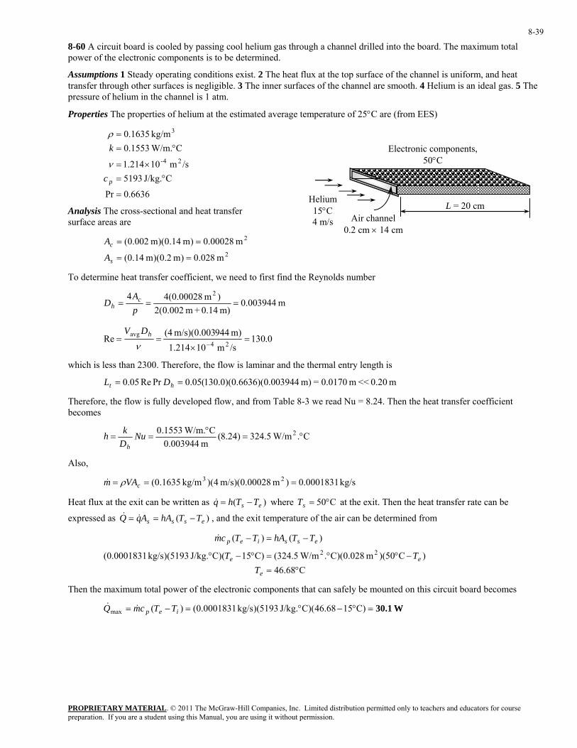
PROPRIETARY MATERIAL. © 2011 The McGraw-Hill Companies, Inc. Limited distribution permitted only to teachers and educators for course preparation. If you are a student using this Manual, you are using it without permission.
8-39
8-60 A circuit board is cooled by passing cool helium gas through a channel drilled into the board. The maximum total power of the electronic components is to be determined.
Assumptions 1 Steady operating conditions exist. 2 The heat flux at the top surface of the channel is uniform, and heat transfer through other surfaces is negligible. 3 The inner surfaces of the channel are smooth. 4 Helium is an ideal gas. 5 The pressure of helium in the channel is 1 atm.
Properties The properties of helium at the estimated average temperature of 25°C are (from EES)
6636.0Pr
CJ/kg. 5193/sm 10214.1
C W/m.1553.0kg/m 1635.0
24-
3
=
°=×=
°==
pc
k
ν
ρElectronic components,
50°C
Helium 15°C 4 m/s Air channel
0.2 cm × 14 cm
L = 20 cmAnalysis The cross-sectional and heat transfer surface areas are
2
2
m 028.0)m 2.0)(m 14.0(
m 00028.0)m 14.0)(m 002.0(
==
==
s
c
A
A
To determine heat transfer coefficient, we need to first find the Reynolds number
m 003944.0m) 0.14+m 002.0(2)m 00028.0(44 2
===pA
D ch
0.130/sm 10214.1m) 944m/s)(0.003 (4Re
24avg =
×==
−νhDV
which is less than 2300. Therefore, the flow is laminar and the thermal entry length is
m 0.20 << m 0.0170=m) 003944.0)(6636.0)(0.130(05.0PrRe05.0 == ht DL
Therefore, the flow is fully developed flow, and from Table 8-3 we read Nu = 8.24. Then the heat transfer coefficient becomes
C. W/m5.324)24.8(m 003944.0
C W/m.1553.0 2 °=°
== NuDkh
h
Also,
kg/s 0001831.0)m 00028.0)(m/s 4)(kg/m 1635.0( 23 === cVAm ρ&
Heat flux at the exit can be written as where at the exit. Then the heat transfer rate can be
expressed as , and the exit temperature of the air can be determined from
)( es TThq −=& C50°=sT
)( esss TThAAqQ −== &&
C68.46
)C50)(m 028.0)(C. W/m5.324()C15)(CJ/kg. 5193)(kg/s 0001831.0(
)()(22
°=−°°=°−°
−=−
e
ee
essiep
TTT
TThATTcm&
Then the maximum total power of the electronic components that can safely be mounted on this circuit board becomes
W30.1=°−°=−= )C1568.46)(CJ/kg. 5193)(kg/s 0001831.0()(max iep TTcmQ &&

PROPRIETARY MATERIAL. © 2011 The McGraw-Hill Companies, Inc. Limited distribution permitted only to teachers and educators for course preparation. If you are a student using this Manual, you are using it without permission.
8-40
8-61 Prob. 8-59 is reconsidered. The effects of air velocity at the inlet of the channel and the maximum surface temperature on the maximum total power dissipation of electronic components are to be investigated.
Analysis The problem is solved using EES, and the solution is given below.
"GIVEN" L=0.20 [m] width=0.14 [m] height=0.002 [m] T_i=15 [C] Vel=4 [m/s] T_s=50 [C] "PROPERTIES" Fluid$='air' c_p=CP(Fluid$, T=T_ave)*Convert(kJ/kg-C, J/kg-C) k=Conductivity(Fluid$, T=T_ave) Pr=Prandtl(Fluid$, T=T_ave) rho=Density(Fluid$, T=T_ave, P=101.3) mu=Viscosity(Fluid$, T=T_ave) nu=mu/rho T_ave=1/2*(T_i+T_e) "ANALYSIS" A_c=width*height A=width*L p=2*(width+height) D_h=(4*A_c)/p Re=(Vel*D_h)/nu "The flow is laminar" L_t=0.05*Re*Pr*D_h "Taking conservative approach and assuming fully developed laminar flow, from Table 8-1 we read" Nusselt=8.24 h=k/D_h*Nusselt m_dot=rho*Vel*A_c Q_dot=h*A*(T_s-T_e) Q_dot=m_dot*c_p*(T_e-T_i)
Vel [m/s]
Q& [W]
1 2 3 4 5 6 7 8 9 10 11 12 13 14 15 16 17 18 19 20
9.438 16.07 20.94 24.64 27.54 29.88 31.79 33.39 34.74 35.9 36.9 37.78 38.55 39.23 39.85 40.4 40.9 41.35 41.76 42.14
2 4 6 8 10 12 14 16 18 205
10
15
20
25
30
35
40
45
Vel [m/s]
Q [
W]

PROPRIETARY MATERIAL. © 2011 The McGraw-Hill Companies, Inc. Limited distribution permitted only to teachers and educators for course preparation. If you are a student using this Manual, you are using it without permission.
8-41
30 40 50 60 70 80 9010
15
20
25
30
35
40
45
50
55
Ts [C]
Q [
W]
Ts [C]
Q& [W]
30 35 40 45 50 55 60 65 70 75 80 85 90
10.58 14.1 17.62 21.13 24.64 28.15 31.65 35.14 38.64 42.13 45.61 49.09 52.56

PROPRIETARY MATERIAL. © 2011 The McGraw-Hill Companies, Inc. Limited distribution permitted only to teachers and educators for course preparation. If you are a student using this Manual, you are using it without permission.
8-42
8-62 Hot air enters a sheet metal duct located in a basement. The exit temperature of hot air and the rate of heat loss are to be determined.
Assumptions 1 Steady flow conditions exist. 2 The inner surfaces of the duct are smooth. 3 The thermal resistance of the duct is negligible. 4 Air is an ideal gas with constant properties. 5 The pressure of air is 1 atm.
Properties We expect the air temperature to drop somewhat, and evaluate the air properties at 1 atm and the estimated bulk mean temperature of 50°C (Table A-15),
7228.0Pr
CJ/kg. 1007 /s;m 10798.1
C W/m.02735.0 ;kg/m 092.125-
3
=
°=×=
°==
pc
k
ν
ρ
T∞ = 10°C Air duct
20 cm × 20 cm
L = 12 m ε = 0.3
Analysis The surface area and the Reynolds number are
m 9.6m) m)(12 2.0(44 =×== aLAs
m 2.04
44 2==== a
aa
pA
D ch
Air 60°C 4 m/s
494,44/sm 10798.1
m) m/s)(0.20 (4Re
25avg =
×==
−νhDV
which is greater than 10,000. Therefore, the flow is turbulent and the entry lengths in this case are roughly
m 0.2m) 2.0(1010 ==≈≈ hth DLL
which is much shorter than the total length of the duct. Therefore, we can assume fully developed turbulent flow for the entire duct, and determine the Nusselt number from
2.109)7228.0()494,44(023.0PrRe023.0 3.08.03.08.0 ====k
hDNu h
and C. W/m93.14)2.109(m 2.0
C W/m.02735.0 2 °=°
== NuDkh
h
The mass flow rate of air is
kg/s 0.1747m/s) )(4m 0.2)(0.2kg/m 092.1( 23 =×== VAm cρ&
In steady operation, heat transfer from hot air to the duct must be equal to the heat transfer from the duct to the surrounding (by convection and radiation), which must be equal to the energy loss of the hot air in the duct. That is,
airhot outrad,+convinconv, EQQQ &&&& ∆===
Assuming the duct to be at an average temperature of Ts , the quantities above can be expressed as
& :Qconv,in
⎟⎟⎠
⎞⎜⎜⎝
⎛−−
−°=→
⎟⎟⎠
⎞⎜⎜⎝
⎛−−
−=∆=
60ln
60)m 6.9)(C. W/m93.14(
ln
22ln
s
es
e
is
es
iesisi
TTT
TQ
TTTT
TTAhTAhQ &&
& :Qconv+rad,out ( )
[ ] 4444282
2244
K)27310()273().K W/m1067.5)(m 0.3(9.6+
C)10)(m C)(9.6. W/m10( )(
+−+×
°−°=→−+−=−
s
sossosso
T
TQTTATTAhQ && σε
∆ & :Ehot air C)C)(60J/kg. kg/s)(1007 1747.0( )( °−°=→−= eiep TQTTcmQ &&&
This is a system of three equations with three unknowns whose solution is
C3.33and , , °=°== se TTQ C45.1 W2622&
Therefore, the hot air will lose heat at a rate of 2622 W and exit the duct at 45.1°C.

PROPRIETARY MATERIAL. © 2011 The McGraw-Hill Companies, Inc. Limited distribution permitted only to teachers and educators for course preparation. If you are a student using this Manual, you are using it without permission.
8-43
8-63 Prob. 8-62 is reconsidered. The effects of air velocity and the surface emissivity on the exit temperature of air and the rate of heat loss are to be investigated.
Analysis The problem is solved using EES, and the solution is given below.
"GIVEN" T_i=60 [C] L=12 [m] side=0.20 [m] Vel=4 [m/s] epsilon=0.3 T_o=10 [C] h_o=10 [W/m^2-C] T_surr=10 [C] "PROPERTIES" Fluid$='air' c_p=CP(Fluid$, T=T_ave)*Convert(kJ/kg-C, J/kg-C) k=Conductivity(Fluid$, T=T_ave) Pr=Prandtl(Fluid$, T=T_ave) rho=Density(Fluid$, T=T_ave, P=101.3) mu=Viscosity(Fluid$, T=T_ave) nu=mu/rho T_ave=T_i-10 "assumed average bulk mean temperature" "ANALYSIS" A=4*side*L A_c=side^2 p=4*side D_h=(4*A_c)/p Re=(Vel*D_h)/nu "The flow is turbulent" L_t=10*D_h "The entry length is much shorter than the total length of the duct." Nusselt=0.023*Re^0.8*Pr^0.3 h_i=k/D_h*Nusselt m_dot=rho*Vel*A_c Q_dot=Q_dot_conv_in Q_dot_conv_in=Q_dot_conv_out+Q_dot_rad_out Q_dot_conv_in=h_i*A*DELTAT_ln DELTAT_ln=(T_e-T_i)/ln((T_s-T_e)/(T_s-T_i)) Q_dot_conv_out=h_o*A*(T_s-T_o) Q_dot_rad_out=epsilon*A*sigma*((T_s+273)^4-(T_surr+273)^4) sigma=5.67E-8 "[W/m^2-K^4], Stefan-Boltzmann constant" Q_dot=m_dot*c_p*(T_i-T_e)
Vel [m/s] Te [C] Q& [W] 1 33.85 1150 2 39.43 1810 3 42.78 2273 4 45.1 2622 5 46.83 2898 6 48.17 3122 7 49.25 3310 8 50.14 3469 9 50.89 3606 10 51.53 3726

PROPRIETARY MATERIAL. © 2011 The McGraw-Hill Companies, Inc. Limited distribution permitted only to teachers and educators for course preparation. If you are a student using this Manual, you are using it without permission.
8-44
ε Te [C] Q& [W] 0.1 45.82 2495 0.2 45.45 2560 0.3 45.1 2622 0.4 44.77 2680 0.5 44.46 2735 0.6 44.16 2787 0.7 43.88 2836 0.8 43.61 2883 0.9 43.36 2928 1 43.12 2970
1 2 3 4 5 6 7 8 9 1032.5
36.5
40.5
44.5
48.5
52.5
1000
1500
2000
2500
3000
3500
4000
Vel [m/s]
T e [
C]
Q [
W]
Te
Q
0.1 0.2 0.3 0.4 0.5 0.6 0.7 0.8 0.9 143
43.5
44
44.5
45
45.5
46
2400
2500
2600
2700
2800
2900
3000
ε
T e [
C]
Q [
W]
Te
Q

PROPRIETARY MATERIAL. © 2011 The McGraw-Hill Companies, Inc. Limited distribution permitted only to teachers and educators for course preparation. If you are a student using this Manual, you are using it without permission.
8-45
8-64 Water flows through a concentric annulus tube with constant inner surface temperature and insulated outer surface, the length of the annulus tube is to be determined.
Assumptions 1 Steady operating conditions exist. 2 Properties are constant. 3 Constant inner tube surface temperature. 4 Insulated outer tube surface. 5 Fully developed flow.
Properties The properties of water at Tb = (Ti + Te)/2 = 50°C: cp = 4181 J/kg·K, k = 0.644 W/m·K, µ = 0.547 × 10⁻³ kg/m·s, and Pr = 3.55 (Table A-15).
Analysis The Reynolds number is
13035
)skg/m 10547.0)(m 1.0m 025.0()kg/s 7.0(4
)(4
))(4/()()(
Re
3
22avg
=⋅×+
=
+=
−
−=
−=
−π
µπµπµρ
ioio
ioio
DDm
DDDDmDDV &&
Since Re > 10000, the flow through the annulus is turbulent. Using the Dittus-Boelter equation, we have
8.74)55.3()13035(023.0PrRe023.0Nu 4.08.04.08.0 ====k
hDh
Hence, the convection heat transfer coefficient is
K W/m3.642m 0750
K W/m644.08.74 2 ⋅=⎟⎠⎞
⎜⎝⎛ ⋅
=.
h
The length of the concentric annulus tube is
m 53.2
=−−
⋅⋅
−=−−
−=2012080120ln
)KW/m3.642)(m 025.0()KJ/kg 4181)(kg/s 7.0(ln 2ππ is
es
ii
p
TTTT
hDcm
L&
Discussion For fully developed turbulent flow, hi ≈ ho, hence the tube annulus can be treated as a noncircular duct with Dh = Do – Di.

PROPRIETARY MATERIAL. © 2011 The McGraw-Hill Companies, Inc. Limited distribution permitted only to teachers and educators for course preparation. If you are a student using this Manual, you are using it without permission.
8-46
8-65 The rectangular tube surface temperature necessary to heat water to the desired outlet temperature of 80°C is to be determined.
Assumptions 1 Steady operating conditions exist. 2 Properties are constant. 3 Constant tube surface temperature.
Properties The properties of water at Tb = (Ti + Te)/2 = 50°C: cp = 4181 J/kg·K, k = 0.644 W/m·K, µ = 0.547 × 10⁻³ kg/m·s, and Pr = 3.55 (Table A-15).
Analysis The hydraulic diameter is
m 03333.0)(2
44=
+==
baab
pA
D ch
The Reynolds number, hydrodynamic and thermal entry lengths are
2300488)skg/m 10547.0)(m 075.0(2
)kg/s 01.0(4)(2
44)/4(Re 3
avg
<=⋅×
=+
====−µµµµ
ρba
mpm
ApAmDV
c
ch &&&
and m 10m 813.0Re05.0lam , <=≈ hh DL m 10m 89.2PrRe05.0lam , <=≈ DLt
Hence, the flow is laminar and fully developed. From Table 8-1 with a/b = 2 for constant surface temperature, we have
→ 39.3Nu = K W/m5.65m 03333.0
K W/m644.039.3Nu 2 ⋅=⎟⎠⎞
⎜⎝⎛ ⋅
==hD
kh
The tube surface temperature can be determined using
⎟⎟⎠
⎞⎜⎜⎝
⎛−−−=
p
sisse cm
hATTTT
&exp)( →
)]/(exp[1)]/(exp[
ps
psies cmhA
cmhATTT
&
&
−−
−−=
C86.3°=−−
−°−°=
)35.2exp(1)35.2exp(C)20(C80
sT
where
35.2)KJ/kg 4181)(kg/s 01.0(
)m 050.0m 025.0)(m 10(2)K W/m5.65( 2=
⋅+⋅
=p
s
cmhA&
Discussion The Nu = 3.39 for rectangular tube with a/b = 2 for laminar fully developed flow with constant surface temperature is slightly lower than its circular tube counterpart, Nu = 3.66.

PROPRIETARY MATERIAL. © 2011 The McGraw-Hill Companies, Inc. Limited distribution permitted only to teachers and educators for course preparation. If you are a student using this Manual, you are using it without permission.
8-47
8-66 The components of an electronic system located in a rectangular horizontal duct are cooled by forced air. The exit temperature of the air and the highest component surface temperature are to be determined.
Assumptions 1 Steady flow conditions exist. 2 The inner surfaces of the duct are smooth. 3 The thermal resistance of the duct is negligible. 4 Air is an ideal gas with constant properties. 5 The pressure of air is 1 atm.
Properties We assume the bulk mean temperature for air to be 35°C since the mean temperature of air at the inlet will rise somewhat as a result of heat gain through the duct whose surface is exposed to a constant heat flux. The properties of air at 1 atm and this temperature are (Table A-15)
220 W
Air duct 16 cm × 16 cm
L = 1 m
7268.0Pr
CJ/kg. 1007/sm 10655.1
C W/m.02625.0kg/m 145.1
25-
3
=
°=×=
°==
pc
k
ν
ρ
Air 27°C
0.65 m3/minAnalysis (a) The mass flow rate of air and the exit temperature are determined from
kg/s 0.0124=kg/min 0.7443=/min)m )(0.65kg/m 145.1( 33== V&& ρm
C42.0°=°
°=+=→−=C)J/kg. kg/s)(1007 0124.0(
W)(0.85)(220+C27)(p
ieiep cmQTTTTcmQ&
&&&
(b) The mean fluid velocity and hydraulic diameter are
m 16.0
m) 16.0(4m) m)(0.16 16.0(44
m/s 0.4232=m/min 4.25m) m)(0.16 (0.16
m/min 65.0
===
===
pA
D
AV
ch
cm
V&
Then
4091/sm 10655.1m) m/s)(0.16 (0.4232Re
25avg =
×==
−νhDV
which is not greater than 10,000 but the components will cause turbulence and thus we can assume fully developed turbulent flow in the entire duct, and determine the Nusselt number from
69.15)7268.0()4091(023.0PrRe023.0 4.08.04.08.0 ====k
hDNu h
and
C. W/m574.2)69.15(m 16.0
C W/m.02625.0 2 °=°
== NuDkh
h
The highest component surface temperature will occur at the exit of the duct. Assuming uniform surface heat flux, its value is determined from
[ ] C155.5°=°
°=+=
−=
C. W/m2.574m) m)(1 4(0.16 W)/(0.85)(220+C0.42
/
)(/
2,
,
hAQ
TT
TThAQ
sehighests
ehighestss
&
&

PROPRIETARY MATERIAL. © 2011 The McGraw-Hill Companies, Inc. Limited distribution permitted only to teachers and educators for course preparation. If you are a student using this Manual, you are using it without permission.
8-48
8-67 The components of an electronic system located in a circular horizontal duct are cooled by forced air. The exit temperature of the air and the highest component surface temperature are to be determined.
Assumptions 1 Steady flow conditions exist. 2 The inner surfaces of the duct are smooth. 3 The thermal resistance of the duct is negligible. 4 Air is an ideal gas with constant properties. 5 The pressure of air is 1 atm.
Properties We assume the bulk mean temperature for air to be 35°C since the mean temperature of air at the inlet will rise somewhat as a result of heat gain through the duct whose surface is exposed to a constant heat flux. The properties of air at 1 atm and this temperature are (Table A-15)
7268.0Pr
CJ/kg. 1007/sm 10655.1
C W/m.02625.0kg/m 145.1
25-
3
=
°=×=
°==
pc
k
ν
ρ
Air 27°C
0.65 m3/min
Electronics, 220 W
D = 15 cm
L = 1 mAnalysis (a) The mass flow rate of air and the exit temperature are determined from
kg/s 0.0124=kg/min 0.7443=/min)m )(0.65kg/m 145.1( 33== V&& ρm
C 42.0 °=°
°=+=→−=C)J/kg. kg/s)(1007 0124.0(
W)(0.85)(220+C 27)(p
ieiep cmQTTTTcmQ&
&&&
(b) The mean fluid velocity is
m/s 0.613=m/min 8.36/4m) (0.15
m/min 65.02avg ===
πcAV V&
Then,
5556/sm 10655.1m) m/s)(0.15 (0.613Re
25avg =
×==
−νhDV
which is not greater than 10,000 but the components will cause turbulence and thus we can assume fully developed turbulent flow in the entire duct, and determine the Nusselt number from
05.20)7268.0()5556(023.0PrRe023.0 4.08.04.08.0 ====k
hDNu h
and
C. W/m51.3)05.20(m 15.0
C W/m.02625.0 2 °=°
== NuDkh
h
The highest component surface temperature will occur at the exit of the duct. Assuming uniform heat flux, its value is determined from
[ ] C155.1°=°
°=+=→−=C. W/m3.51
m) m)(1 (0.15 W)/(0.85)(220+C0.42)( 2,,π
hqTTTThq ehighestsehighests&
&

PROPRIETARY MATERIAL. © 2011 The McGraw-Hill Companies, Inc. Limited distribution permitted only to teachers and educators for course preparation. If you are a student using this Manual, you are using it without permission.
8-49
8-68E Water is heated by passing it through thin-walled copper tubes. The length of the copper tube that needs to be used is to be determined.
Assumptions 1 Steady flow conditions exist. 2 The inner surfaces of the tube are smooth. 3 The thermal resistance of the tube is negligible. 4 The temperature at the tube surface is constant.
Properties The properties of water at the bulk mean fluid temperature of F1002/)14060(, °=+=avgbT are (Table A-9E)
54.4Pr
FBtu/lbm. 999.0/sft 10738.0/
FBtu/h.ft. 363.0lbm/ft 0.62
25-
3
=
°=×==
°==
pc
k
ρµν
ρ
140°F
250°F
D = 0.75 in
L
Water 60°F
0.4 lbm/s
Analysis (a) The mass flow rate and the Reynolds number are
ft/s 10.2/4]ft) (0.75/12)[lbm/ft (62
lbm/s 4.023avgavg ===→=
πρρ
cc A
mVVAm&
&
810,17/sft 10738.0ft) /12ft/s)(0.75 (2.10Re
25avg =
×==
−νhDV
which is greater than 10,000. Therefore, the flow is turbulent and the entry lengths in this case are roughly
in 5.7in) 75.0(1010 ==≈≈ DLL th
which is probably shorter than the total length of the pipe we will determine. Therefore, we can assume fully developed turbulent flow in the entire duct, and determine the Nusselt number from
9.105)54.4()810,17(023.0PrRe023.0 4.08.04.08.0 ====k
hDNu h
and F.Btu/h.ft 615)9.105(ft )12/75.0(
FBtu/h.ft. 363.0 2 °=°
== NuDkh
h
The logarithmic mean temperature difference and then the rate of heat transfer per ft length of the tube are
Btu/h675,17)F4.146(ft)] 1)(ft 12/75.0()[F.Btu/h.ft 615(
F4.146
60250140250ln
60140
ln
2lm
lm
=°°=∆=
°=⎟⎠⎞
⎜⎝⎛
−−
−=
⎟⎟⎠
⎞⎜⎜⎝
⎛−−
−=∆
πThAQ
TTTT
TTT
s
is
es
ie
&
The rate of heat transfer needed to raise the temperature of water from 60°F to 140°F is
Btu/h 115,085=F60)F)(140Btu/lbm. 99lbm/h)(0.9 36004.0()( °−°×=−= iep TTcmQ &&
Then the length of the copper tube that needs to be used becomes
ft 6.51==Btu/h 675,17Btu/h 085,115Length
(b) The friction factor, the pressure drop, and then the pumping power required to overcome this pressure drop can be determined for the case of fully developed turbulent flow to be
02598.0)810,17(184.0Re184.0 2.02.0 === −−f
hp 0.00013=⎟⎠⎞
⎜⎝⎛
⋅=
∆=
=⎟⎠
⎞⎜⎝
⎛⋅
==∆
ft/slbf 550hp 1
lbm/ft 62)lbf/ft 50.11)(lbm/s 4.0(
lbf/ft 50.11ft/slbm 32.174
lbf 12
)ft/s 10.2)(lbm/ft 62(ft) 12/75.0(
ft) 51.6(02598.02
3
2
22
232avg
ρ
ρ
PmW
VDLfP
pump&&

PROPRIETARY MATERIAL. © 2011 The McGraw-Hill Companies, Inc. Limited distribution permitted only to teachers and educators for course preparation. If you are a student using this Manual, you are using it without permission.
8-50
8-69 A computer is cooled by a fan blowing air through its case. The flow rate of the air, the fraction of the temperature rise of air that is due to heat generated by the fan, and the highest allowable inlet air temperature are to be determined.
Assumptions 1 Steady flow conditions exist. 2 Heat flux is uniformly distributed. 3 Air is an ideal gas with constant properties. 4 The pressure of air is 1 atm.
Properties We assume the bulk mean temperature for air to be 25°C. The properties of air at 1 atm and this temperature are (Table A-15)
0.7296Pr
CJ/kg. 1007/sm 10562.1
C W/m.02551.0kg/m 184.1
25-
3
=
°=×=
°==
pc
k
ν
ρ
Analysis (a) Noting that the electric energy consumed by the fan is converted to thermal energy, the mass flow rate of air is
Cooling air
kg/s 0.01053=°°
+×=
−
+=→−=
C)C)(10J/kg. (1007 W)10 12(8
)()( fan elect,
iepiep TTc
WQmTTcmQ
&&&&&
(b) The fraction of temperature rise of air that is due to the heat generated by the fan and its motor is
9.43%==°
°
°=°
==∆→∆=
0943.0C10
C0.943=
C943.0C)J/kg. kg/s)(1007 (0.01053
W10
f
cmQTTcmQ
pp &
&&&
(c) The mean velocity of air is
[ ]
m/s 088.3)m 12.0)(m 003.0()kg/m (1.184
kg/s )8/01053.0(3avgavg ===→=
cc A
mVVAmρ
ρ&
&
and m 00585.0m) 12.0m 003.0(2m) m)(0.12 003.0(44
=+
==PA
D ch
Therefore,
1157/sm 10562.1
m) 85m/s)(0.005 (3.088Re 25avg =
×==
−νhDV
which is less than 2300. Therefore, the flow is laminar. Assuming fully developed flow, the Nusselt number is determined from Table 8-4 corresponding to a/b = 12/0.3 = 40 to be Nu = 8.24. Then,
C. W/m9.35)24.8(m 00585.0
C W/m.02551.0 2 °=°
== NuDkh
h
The highest component surface temperature will occur at the exit of the duct. Assuming uniform heat flux, the air temperature at the exit is determined from
C0.60C. W/m35.9
]m 0.15)0.003+0.152(0.12 W]/[8)10128[(C70 )( 2
2
max,max, °=°
×××+×−°=−=→−=
hqTTTThq sees&
&
The highest allowable inlet temperature then becomes
C50.0°=°−°=°−=→°=− C10C0.60C10C10 eiie TTTT
Discussion Although the Reynolds number is less than 2300, the flow in this case will most likely be turbulent because of the electronic components that that protrude into flow. Therefore, the heat transfer coefficient determined above is probably conservative.

PROPRIETARY MATERIAL. © 2011 The McGraw-Hill Companies, Inc. Limited distribution permitted only to teachers and educators for course preparation. If you are a student using this Manual, you are using it without permission.
8-51
8-70 A tube with constant surface heat flux, the convection heat transfer coefficients at the tube outlet are to be determined for water, engine oil, and liquid mercury.
Assumptions 1 Steady operating conditions exist. 2 Properties are constant.
Properties The properties of water, engine oil, and liquid mercury at Tb = (Ti + Te)/2 = 100°C are listed in the following table:
Liquid cp, J/kg·K k, W/m·K µ, kg/m·s Pr
Water (Table A-9) 4217 0.679 0.282 × 10⁻³ 1.75
Engine oil (Table A-13) 2220 0.1367 17.18 × 10⁻³ 279.1
Liq. mercury (Table A-14) 137.1 9.46706 1.245 × 10⁻³ 0.0180
Analysis The hydrodynamic and thermal entry lengths can be calculated using the following equations:
, , where DLh Re05.0lam , ≈ DLt PrRe05.0lam , ≈µπD
m&4Re =
Hence, the calculated Reynolds numbers, hydrodynamic and thermal entry lengths are
Liquid Pr Re Lh, lam, m Lt, lam, m
Water 1.75 1806 2.258 3.951
Engine oil 279.1 29.64 0.03706 10.34
Liq. mercury 0.018 409.1 0.5113 0.009204
Since the Reynolds numbers are less than 2300, and the hydrodynamic and thermal entry lengths are less than 15 m, therefore the flow is laminar and fully developed at the tube outlet. Hence, the Nusselt number for constant surface heat flux is Nu = 4.36. The convection heat transfer coefficients at the tube outlet are
Liquid h = (k/D)Nu, W/m2·K
Water 118
Engine oil 23.8
Liq. mercury 1650
Discussion Liquid mercury has high h due to its large k value.

PROPRIETARY MATERIAL. © 2011 The McGraw-Hill Companies, Inc. Limited distribution permitted only to teachers and educators for course preparation. If you are a student using this Manual, you are using it without permission.
8-52
8-71 The tube surface temperatures necessary to heat water, engine oil, and liquid mercury to the desired outlet temperature of 150°C are to be determined.
Assumptions 1 Steady operating conditions exist. 2 Properties are constant. 3 Constant tube surface temperature.
Properties The properties of water, engine oil, and liquid mercury at Tb = (Ti + Te)/2 = 100°C are listed in the following table:
Liquid cp, J/kg·K k, W/m·K µ, kg/m·s Pr
Water (Table A-9) 4217 0.679 0.282 × 10⁻³ 1.75
Engine oil (Table A-13) 2220 0.1367 17.18 × 10⁻³ 279.1
Liq. mercury (Table A-14) 137.1 9.46706 1.245 × 10⁻³ 0.0180
Analysis The hydrodynamic and thermal entry lengths can be calculated using the following equations:
, , where DLh Re05.0lam , ≈ DLt PrRe05.0lam , ≈µπD
m&4Re =
Hence, the calculated Reynolds numbers, hydrodynamic and thermal entry lengths are
Liquid Pr Re Lh, lam, m Lt, lam, m
Water 1.75 1806 2.258 3.951
Engine oil 279.1 29.64 0.03706 10.34
Liq. mercury 0.018 409.1 0.5113 0.009204
Since the Reynolds numbers are less than 2300, and the hydrodynamic and thermal entry lengths are less than 15 m, therefore the flow is laminar and fully developed at the tube outlet. Hence, the Nusselt number for constant surface temperature is Nu = 3.66. The convection heat transfer coefficients and the tube surface temperatures can be determined using
NuDkh =
and ⎟⎟⎠
⎞⎜⎜⎝
⎛−−−=
p
sisse cm
hATTTT
&exp)( →
)]/(exp[1)]/(exp[
ps
psies cmhA
cmhATTT
&
&
−−
−−=
The calculated convection heat transfer coefficients and tube surface temperatures are
Liquid h, W/m2·K Ts, °C
Water 99.4 157
Engine oil 20.0 203
Liq. mercury 1390 150
Discussion Liquid metals such as mercury, due to their high thermal conductivities, are particularly applicable to cases where large amount of energy must be removed from a relatively small space.

PROPRIETARY MATERIAL. © 2011 The McGraw-Hill Companies, Inc. Limited distribution permitted only to teachers and educators for course preparation. If you are a student using this Manual, you are using it without permission.
8-53
8-72 Air at 20°C (1 atm) enters into a 5-mm diameter and 10-cm long circular tube, the convection heat transfer coefficient and the outlet mean temperature are to be determined.
Assumptions 1 Steady operating conditions exist. 2 Properties are constant. 3 Constant tube surface temperature.
Properties The properties of air at 50°C: cp = 1007 J/kg·K, k = 0.02735 W/m·K, ρ = 1.092 kg/m3, µ = 1.963 × 10⁻⁵ kg/m·s, ν = 1.798 × 10⁻⁵ m2/s, and Pr = 0.7228; at Ts = 160°C: µs = 2.420 × 10⁻⁵ kg/m·s (Table A-15).
Analysis The Reynolds number, hydrodynamic and thermal entry lengths are
23001390)/sm 10798.1(
)m 005.0)(m/s 5(Re 25avg <=
×==
−νDV
(laminar flow)
and cm 10cm 8.34Re05.0lam , >=≈ DLh cm 10cm 1.25PrRe05.0lam , >=≈ DLt
Therefore the flow is laminar, hydrodynamically and thermally developing. The appropriate equation to determine the Nusselt number is from (Sieder and Tate, 1936)
665.6420.2963.1
m 1.0)m 005.0)(7228.0)(1390(86.1PrRe86.1Nu
14.03/114.03/1
=⎟⎠⎞
⎜⎝⎛
⎥⎦⎤
⎢⎣⎡=⎟⎟
⎠
⎞⎜⎜⎝
⎛⎟⎠⎞
⎜⎝⎛=
s
b
LD
µµ
K W/m36.5 2 ⋅== NuDkh
The outlet mean temperature is
C77.7°=⎥⎥⎦
⎤
⎢⎢⎣
⎡
⋅×⋅
−°−°−°=
⎟⎟⎠
⎞⎜⎜⎝
⎛−−−=
− )KJ/kg 1007)(kg/s 10072.1()m 1.0)(m 005.0()K W/m5.36(exp)C20C160(C160
exp)(
4
2 π
p
sisse cm
hATTTT
&
where
kg/s 10072.14/ 42avg
−×== DVm πρ&
Discussion Note that the bulk mean temperature is Tb = (Ti + Te)/2 = 48.9°C, thus evaluating the air properties at 50°C is reasonable.

PROPRIETARY MATERIAL. © 2011 The McGraw-Hill Companies, Inc. Limited distribution permitted only to teachers and educators for course preparation. If you are a student using this Manual, you are using it without permission.
8-54
8-73 Air (1 atm) enters into a 5-cm diameter circular tube at 20°C with an average velocity of 5 m/s. The length of the tube is to be determined.
Assumptions 1 Steady operating conditions exist. 2 Properties are constant. 3 Constant tube surface temperature.
Properties The properties of air at Tb = (Ti + Te)/2 = 50°C: cp = 1007 J/kg·K, k = 0.02735 W/m·K, ρ = 1.092 kg/m3, µ = 1.963 × 10⁻⁵ kg/m·s, ν = 1.798 × 10⁻⁵ m2/s, and Pr = 0.7228 (Table A-15).
Analysis The Reynolds number is
000,1013904)/sm 10798.1(
)m 05.0)(m/s 5(Re 25avg >=
×==
−νDV
(turbulent flow)
Since the flow is turbulent, we can use the Dittus-Boelter equation to calculate the Nusselt number:
→ 67.41)7228.0()13904(023.0PrRe023.0Nu 4.08.04.08.0 === KW/m22.8 2 ⋅= h
The length of the tube can be determined using
pp
s
is
es
cmDLh
cmhA
TTTT
&&
π−=−=
−−
ln where kg/s 01072.04/2avg == DVm πρ&
Hence, length of the tube is
m 1.69
=−−
⋅⋅
−=−−
−=2016080160ln
)KW/m22.8)(m 05.0()KJ/kg 1007)(kg/s 01072.0(ln 2ππ is
esp
TTTT
Dhcm
L&
Discussion Since L/D = 33.8 > 10, the turbulent flow is fully developed.

PROPRIETARY MATERIAL. © 2011 The McGraw-Hill Companies, Inc. Limited distribution permitted only to teachers and educators for course preparation. If you are a student using this Manual, you are using it without permission.
8-55
Special Topic: Transitional Flow
8-74 A liquid mixture flowing in a tube with a bell-mouth inlet is subjected to uniform wall heat flux. The friction coefficient is to be determined.
Assumptions Steady operating conditions exist.
Properties The properties of the ethylene glycol-distilled water mixture are given to be Pr = 14.85, ν = 1.93×10⁻⁶ m2/s and µb/µs = 1.07.
Analysis: For the calculation of the non-isothermal fully developed friction coefficient, it is necessary to determine the flow regime before making any decision regarding which friction coefficient relation to use. The Reynolds number at the specified location is
( )5973
/sm1093.1m0158.0)]m10961.1/()/sm1043.1[()/(
Re26
2434=
×
××==
−
−−
νDAcV&
since 2422 m10961.14/m)0158.0(4/ −×=== ππ DAc
From Table 8-6, we see that for a bell-mouth inlet and a heat flux of 3 kW/m2 the flow is in the transition region. Therefore, Eq. 8-81 applies. Reading the constants A, B, C and m1, m2, m3, and m4 from Table 8-5, the friction coefficient is determined to be
( ) 0.0073=⎥⎥⎦
⎤
⎢⎢⎣
⎡⎟⎠⎞
⎜⎝⎛+=
⎟⎟⎠
⎞⎜⎜⎝
⎛
⎥⎥⎦
⎤
⎢⎢⎣
⎡⎟⎠⎞
⎜⎝⎛+=
××−−
−−− 46.241.0 85.141660042.058.2
32.6099.0
trans,
07.1534059731
Re1m
s
bCB
f AC
µµ
8-75 A liquid mixture flowing in a tube with a bell-mouth inlet is subjected to uniform wall heat flux. The friction coefficient is to be determined.
Assumptions Steady operating conditions exist.
Properties The properties of the ethylene glycol-distilled water mixture are given to be Pr = 14.85, ν = 1.93×10⁻⁶ m2/s and µb/µs = 1.07.
Analysis: For the calculation of the non-isothermal fully developed friction coefficient, it is necessary to determine the flow regime before making any decision regarding which friction coefficient relation to use. If the volume flow rate is increased by 50%, the Reynolds number becomes
( )8960
/sm1093.1m0158.0)]m10961.1/()/sm1043.15.1[()/(
Re26
2434=
×
×××==
−
−−
νDAcV&
since 2422 m10961.14/m)0158.0(4/ −×=== ππ DAc
From Table 8-6 for a bell-mouth inlet and a heat flux of 3 kW/m2, the flow is in the turbulent region. To calculate the fully developed friction coefficient for this case, Eq. 8-80 for turbulent flow with m = - 0.25 is used.
( ) 0.0080=⎟⎠
⎞⎜⎝
⎛=⎟⎟
⎠
⎞⎜⎜⎝
⎛⎟⎠
⎞⎜⎝
⎛= − 25.0
25.025.0turb, 07.18960
0791.0Re
0791.0m
s
bfC
µµ

PROPRIETARY MATERIAL. © 2011 The McGraw-Hill Companies, Inc. Limited distribution permitted only to teachers and educators for course preparation. If you are a student using this Manual, you are using it without permission.
8-56
8-76 A liquid mixture flowing in a tube is subjected to uniform wall heat flux. The Nusselt number at a specified location is to be determined for two different tube inlet configurations.
Assumptions Steady operating conditions exist.
Properties The properties of the ethylene glycol-distilled water mixture are given to be Pr = 33.46, ν = 3.45×10⁻⁶ m2/s and µb/µs = 2.0.
Analysis For a tube with a known diameter and volume flow rate, the type of flow regime is determined before making any decision regarding which Nusselt number correlation to use. The Reynolds number at the specified location is
( )4790
/sm1045.3m0158.0)]m10961.1/()/sm1005.2[()/(
Re26
2434=
×
××==
−
−−
νDAcV&
since . 2422 m10961.14/m)0158.0(4/ −×=== ππ DAc
Therefore, the flow regime is in the transition region for all three inlet configurations (thus use the information given in Table 8-8 with x/D = 10) and therefore Eq. 8-83 should be used with the constants a, b, c found in Table 8-7. However, Nulam and Nuturb are the inputs to Eq. 8-83 and they need to be evaluated first from Eqs. 8-84 and 8-85, respectively. It should be mentioned that the correlations for Nulam and Nuturb have no inlet dependency.
From Eq. 8-84:
( )
( ) 4.35)0.2(]46.33)(000,60[025.010
)46.33)(4790(24.1
GrPr025.0PrRe24.1Nu
14.03/1
75.0
14.03/175.0
lam
=⎥⎦
⎤⎢⎣
⎡+⎟
⎠
⎞⎜⎝
⎛=
⎟⎟⎠
⎞⎜⎜⎝
⎛⎥⎦
⎤⎢⎣
⎡+⎟
⎠⎞
⎜⎝⎛=
s
b
xD
µµ
From Eq. 8-85:
( ) ( ) 1.850.210)46.33()4790(023.0
PrRe023.0Nu
14.00054.0385.08.0
14.00054.0385.08.0
turb
==
⎟⎟⎠
⎞⎜⎜⎝
⎛⎟⎠⎞
⎜⎝⎛=
−
−
s
b
Dx
µµ
Then the transition Nusselt number can be determined from Eq. 8-83,
( )[ ]{ }ccba turblamtrans NuReexpNuNu +−+=
Case 1: For bell-mouth inlet:
( )[ ]{ } 35.4=+−+=−− 980.0980.0
trans 1.8523747906628exp4.35Nu
Case 2: For re-entrant inlet:
( )[ ]{ } 92.9=+−+=−− 955.0955.0
trans 1.8527647901766exp4.35Nu
Discussion Comparing the two results, it can be seen that under the same conditions, the Nusselt number for the re-entrant inlet is much higher than that for the bell-mouth inlet. To verify this trend, refer to Fig. 8-37.

PROPRIETARY MATERIAL. © 2011 The McGraw-Hill Companies, Inc. Limited distribution permitted only to teachers and educators for course preparation. If you are a student using this Manual, you are using it without permission.
8-57
8-77 A liquid mixture flowing in a tube is subjected to uniform wall heat flux. The Nusselt number at a specified location is to be determined for two different tube inlet configurations.
Assumptions Steady operating conditions exist.
Properties The properties of the ethylene glycol-distilled water mixture are given to be Pr = 33.46, ν = 3.45×10⁻⁶ m2/s and µb/µs = 2.0.
Analysis For a tube with a known diameter and volume flow rate, the type of flow regime is determined before making any decision regarding which Nusselt number correlation to use. The Reynolds number at the specified location is
( )4790
/sm1045.3m0158.0)]m10961.1/()/sm1005.2[()/(
Re26
2434=
×
××==
−
−−
νDAcV&
since . 2422 m10961.14/m)0158.0(4/ −×=== ππ DAc
Therefore, the flow regime is in the transition region for all three inlet configurations (thus use the information given in Table 8-8 with x/D = 90) and therefore Eq. 8-83 should be used with the constants a, b, c found in Table 8-7. However, Nulam and Nuturb are the inputs to Eq. 8-83 and they need to be evaluated first from Eqs. 8-84 and 8-85, respectively. It should be mentioned that the correlations for Nulam and Nuturb have no inlet dependency.
From Eq. 8-84:
( )
( ) 0.20)0.2(]46.33)(000,60[025.090
)46.33)(4790(24.1
GrPr025.0PrRe24.1Nu
14.03/1
75.0
14.03/175.0
lam
=⎥⎦
⎤⎢⎣
⎡+⎟
⎠
⎞⎜⎝
⎛=
⎟⎟⎠
⎞⎜⎜⎝
⎛⎥⎦
⎤⎢⎣
⎡+⎟
⎠⎞
⎜⎝⎛=
s
b
xD
µµ
From Eq. 8-85:
( ) ( ) 1.840.290)46.33()4790(023.0
PrRe023.0Nu
14.00054.0385.08.0
14.00054.0385.08.0
turb
==
⎟⎟⎠
⎞⎜⎜⎝
⎛⎟⎠⎞
⎜⎝⎛=
−
−
s
b
Dx
µµ
Then the transition Nusselt number can be determined from Eq. 8-83,
( )[ ]{ }ccba turblamtrans NuReexpNuNu +−+=
Case 1: For bell-mouth inlet:
( )[ ]{ } 20.0=+−+=−− 980.0980.0
trans 1.8423747906628exp0.20Nu
Case 2: For re-entrant inlet:
( )[ ]{ } 76.9=+−+=−− 955.0955.0
trans 1.8427647901766exp0.20Nu
Discussion Comparing the two results, it can be seen that under the same conditions, the Nusselt number for the re-entrant inlet is much higher than that for the bell-mouth inlet. To verify this trend, refer to Fig. 8-37.

PROPRIETARY MATERIAL. © 2011 The McGraw-Hill Companies, Inc. Limited distribution permitted only to teachers and educators for course preparation. If you are a student using this Manual, you are using it without permission.
8-58
8-78E A liquid mixture flowing in a tube with a bell-mouth inlet is subjected to uniform wall heat flux. The friction coefficient is to be determined.
Assumptions Steady operating conditions exist.
Properties The properties of the ethylene glycol-distilled water mixture are given to be Pr = 13.8, ν = 18.4×10⁻⁶ ft2/s and µb/µs = 1.12.
Analysis: For the calculation of the non-isothermal fully developed friction coefficient, it is necessary to determine the flow regime before making any decision regarding which friction coefficient relation to use. The Reynolds number at the specified location is
( )6425
gal/min8.448/sft1
/sft104.18ft12/622.0)]ft1011.2/()gal/min16.2[()/(
Re3
6
23
2=⎟
⎟⎠
⎞⎜⎜⎝
⎛
×
×==
−
−
νDAcV&
since 2322 ft10110.24/ft)12/622.0(4/ −×=== ππ DAc
From Table 8-6, the transition Reynolds number range for this case is 3860 < Re < 5200, which means that the flow in this case is turbulent and Eq. 8-80 is the appropriate equation to use. It gives
( ) 0.00859=⎟⎠
⎞⎜⎝
⎛=⎟⎟
⎠
⎞⎜⎜⎝
⎛⎟⎠
⎞⎜⎝
⎛= − 25.0
25.025.0turb 12.16425
0791.0Re
0791.0m
s
bf,C
µµ
Repeating the calculations when the volume flow rate is increased by 50%, we obtain
( )9639
gal/min8.448/sft1
/sft104.18ft12/622.0)]ft1011.2/()gal/min16.2(5.1[)/(
Re3
6
23
2=⎟
⎟⎠
⎞⎜⎜⎝
⎛
×
×==
−
−
νDAcV&
( ) 0.00776=⎟⎠
⎞⎜⎝
⎛=⎟⎟
⎠
⎞⎜⎜⎝
⎛⎟⎠
⎞⎜⎝
⎛= − 25.0
25.025.0turb 12.19639
0791.0Re
0791.0m
s
bf,C
µµ

PROPRIETARY MATERIAL. © 2011 The McGraw-Hill Companies, Inc. Limited distribution permitted only to teachers and educators for course preparation. If you are a student using this Manual, you are using it without permission.
8-59
Review Problems
8-79 Air is flowing through a thin smooth copper tube that is submerged in the nearby lake; the necessary copper tube length for the air to exit with an outlet mean temperature of 20°C is to be determined.
Assumptions 1 Steady operating conditions exist. 2 Properties are constant. 3 Constant tube surface temperature. 4 Conduction through the copper tube wall is negligible.
Properties The properties of air at Tb = (Ti + Te)/2 = 25°C: cp = 1007 J/kg·K, k = 0.02551 W/m·K, ρ = 1.184 kg/m3, ν = 1.562 × 10⁻⁵ m2/s, and Pr = 0.7296 (Table A-15).
Analysis The Reynolds number is
000,1016005)/sm 10562.1(
)m 1.0)(m/s 5.2(Re 25avg >=
×==
−νDV
(turbulent flow)
Since the flow inside the copper tube is turbulent, we can use the Dittus-Boelter equation to calculate the Nusselt number:
31.48)7296.0()16005(023.0PrRe023.0Nu 3.08.04.08.0 === → KW/m32.12 2 ⋅= h
The length of the copper tube can be determined using
⎟⎟⎠
⎞⎜⎜⎝
⎛−−−=
pisse cm
DLhTTTT&
πexp)(
where the surface temperature of the tube can be determined by applying energy balance on the tube surface:
))(()( ∞−=− TTDLhTTcm soeip π& where kg/s 02325.04/2avg == DVm πρ&
Copy the following lines and paste on a blank EES screen to solve the above equation: c_p=1007 D=0.1 h=12.32 h_o=1000 T_i=30 T_e=20 T_inf=15 V_avg=2.5 mdot=0.02325 mdot*c_p*(T_i-T_e)=h_o*pi#*D*L*(T_s-T_inf) T_e=T_s-(T_s-T_i)*exp(-h*pi#*D*L/(mdot*c_p))
Solving by EES software, the necessary copper tube length is
L = 6.74 m
Discussion It is reasonable to neglect heat conduction through the copper tube wall, since copper has high thermal conductivity and the tube wall is thin.

PROPRIETARY MATERIAL. © 2011 The McGraw-Hill Companies, Inc. Limited distribution permitted only to teachers and educators for course preparation. If you are a student using this Manual, you are using it without permission.
8-60
8-80 Liquid mercury flowing through a tube, the tube length is to be determined using (a) the appropriate Nusselt number relation for liquid metals and (b) the Dittus-Boelter equation. The results of (a) and (b) are to be compared.
Assumptions 1 Steady operating conditions exist. 2 Properties are constant. 3 Constant tube surface temperature. 4 Fully developed flow.
Properties The properties of liquid mercury at Tb = (Ti + Te)/2 = 150°C: cp = 136.1 J/kg·K, k = 10.0778 W/m·K, µ = 1.126×10⁻³ kg/m·s, and Pr = 0.0152; at Ts = 250°C: Prs = 0.0119 (Table A-14).
Analysis The Reynolds number is
000,1013570)skg/m 10126.1)(m 05.0(
)kg/s 6.0(44Re 3 >=⋅×
==−πµπD
m& (turbulent flow)
(a) The flow is turbulent and the appropriate Nusselt number relation for liquid metals is
624.5)0119.0()13570(0156.08.4PrRe0156.08.4Nu 93.085.093.085.0 =+=+= s
KW/m1134Nu)/( 2 ⋅== Dkh
Hence, length of the tube is
m 0.504
=−−
⋅⋅
−=−−
−=100250200250ln
)KW/m1134)(m 05.0()KJ/kg 1.136)(kg/s 6.0(ln 2ππ is
esp
TTTT
Dhcm
L&
(b) Using the Dittus-Boelter equation, we have
→ 72.8)0152.0()13570(023.0PrRe023.0Nu 4.08.04.08.0 === KW/m1758 2 ⋅= h
Hence, length of the tube is
m 0.325
=−−
⋅⋅
−=−−
−=100250200250ln
)KW/m1758)(m 05.0()KJ/kg 1.136)(kg/s 6.0(ln 2ππ is
esp
TTTT
Dhcm
L&
(c) Comparing the results calculated for (a) and (b) showed that when using the Dittus-Boelter equation, the tube length is underestimated by approximately 36%.
Discussion When using the relations for calculating Nusselt number, it is necessary to consider their applicability and their associated limits and conditions.

PROPRIETARY MATERIAL. © 2011 The McGraw-Hill Companies, Inc. Limited distribution permitted only to teachers and educators for course preparation. If you are a student using this Manual, you are using it without permission.
8-61
8-81 The convection heat transfer coefficients for air (a) flowing through and (b) flowing across a thin-walled tube are to be determined.
Assumptions 1 Steady operating conditions exist. 2 Properties are constant. 3 Constant tube surface temperature. 4 Fully developed flow.
Properties The properties of air at 50°C: k = 0.02735 W/m·K, ν = 1.798 × 10⁻⁵ m2/s, and Pr = 0.7228 (Table A-15).
Analysis The Reynolds number is
69522)/sm 10798.1(
)m 05.0)(m/s 25(Re 25avg =
×==
−νDV
(a) The flow inside the tube is turbulent (Re > 10,000), and using the Dittus-Boelter equation, we have
151)7228.0()69522(023.0PrRe023.0Nu 4.08.04.08.0 ===
Hence the convection heat transfer coefficient is
K W/m82.6 2 ⋅=⎟⎠⎞
⎜⎝⎛ ⋅
== 151m 050
K W/m027350Nu.
.Dkh (internal forced convection)
(b) Using the Zukauskas (1972) equation from Table 7-1, we have
192)7228.0()69522(027.0PrRe027.0Nu 3/1805.03/1805.0 ===
Hence the convection heat transfer coefficient is
K W/m105 2 ⋅=⎟⎠⎞
⎜⎝⎛ ⋅
== 192m 050
K W/m027350Nu.
.Dkh (external forced convection)
Discussion The convection heat transfer coefficient for the case when air is flowing across the tube outer surface is approximately 27% larger than the case when air is flowing inside the tube.

PROPRIETARY MATERIAL. © 2011 The McGraw-Hill Companies, Inc. Limited distribution permitted only to teachers and educators for course preparation. If you are a student using this Manual, you are using it without permission.
8-62
8-82 A silicon chip is cooled by passing water through microchannels etched in the back of the chip. The outlet temperature of water and the chip power dissipation are to be determined.
Assumptions 1 Steady operating conditions exist. 2 The flow of water is fully developed. 3 All the heat generated by the circuits on the top surface of the chip is transferred to the water.
12 mm Te
T,i
12 mm
Circuits generating power W e
&
W
H
Chip, Ts
Cap, Ts
Analysis (a) The mass flow rate for one channel, the hydraulic diameter, and the Reynolds number are
kg/s 10333.860
kg/s 005.0 5
channel
total −×===nm
m&
&
m 108m 80)20050(2)20050(4
)(2)(44 5-×==
+×
=+×
== µWHWH
pADh
2.748s)kg/m 10891.0)(m 1020050(
)m 10kg/s)(8 10333.8(Re 3212
-55=
⋅×××
××====
−−
−
µµρρ
µρ
c
h
c
hh
ADm
AVDmVD &&
which is smaller than 2300. Therefore, the flow is laminar. We take fully developed laminar flow in the entire duct. The Nusselt number in this case is
66.3=Nu
Heat transfer coefficient is
C. W/m770,27)66.3(m 108
C W/m.607.0 25
°=×
°==
−Nu
Dkh
Next we determine the exit temperature of water
2-62 m 106mm 6=)122.0(2)1205.0(222 ×=×+×=+= HLWLA
K 312.8=⎥⎥⎦
⎤
⎢⎢⎣
⎡
×
×−−−=−−=
−
−−
)4180)(10333.8()106)(770,27(exp)290350(350)( 5
6)/( pcmhA
isse eTTTT &
Then the rate of heat transfer becomes
W96.12C)8.312350)(CJ/kg. 4180)(kg/s 10333.8()( 5 =°−°×=−= −iep TTcmQ &&
(b) Noting that there are 60 such channels, the chip power dissipation becomes
W777=== W)96.12(60channel onechannelQNWe&&

PROPRIETARY MATERIAL. © 2011 The McGraw-Hill Companies, Inc. Limited distribution permitted only to teachers and educators for course preparation. If you are a student using this Manual, you are using it without permission.
8-63
8-83 Water is heated by passing it through five identical tubes that are maintained at a specified temperature. The rate of heat transfer and the length of the tubes necessary are to be determined.
Assumptions 1 Steady flow conditions exist. 2 The surface temperature is constant and uniform. 3 The inner surfaces of the tubes are smooth. 4 Heat transfer to the surroundings is negligible.
Properties The properties of water at the bulk mean fluid temperature of (15+35)/2=25ºC are (Table A-9)
14.6Pr
CJ/kg. 4180/sm 10891.0
C W/m.607.0kg/m 997
23-
3
=
°=×=
°==
pc
k
µ
ρ
D = 5 cm
35ºC
60ºC
Water 15ºC
10 kg/s
5 tubesAnalysis (a) The rate of heat transfer is
W836,000=°−°=−= C)1535)(CJ/kg. 4180)(kg/s 10()( iep TTcmQ &&
(b) The water velocity is
m/s 02.14/m) (0.05)kg/m 997(
kg/s )5/10(23
===πρ cA
mV&
The Reynolds number is
067,57skg/m 10891.0
m) m/s)(0.05 )(1.02kg/m (997Re
3
3=
⋅×==
−µρVD
which is greater than 10,000. Therefore, we have turbulent flow. Assuming fully developed flow in the entire tube, the Nusselt number is determined from
5.303)14.6()067,57(023.0PrRe023.0 4.08.04.08.0 ====k
hDNu h
Heat transfer coefficient is
C. W/m3684)5.303(m 05.0
C W/m.607.0 2 °=°
== NuDkh
Considering that there are 5 tubes, the logarithmic mean temperature difference, the surface area and the lenghth of the tubes are determined as follows:
C03.34
15603560ln
3515
lnlm °=
⎟⎠⎞
⎜⎝⎛
−−
−=
⎟⎟⎠
⎞⎜⎜⎝
⎛−−
−=∆
is
es
ei
TTTT
TTT
22lm m668.6)C03.34()C. W/m3684( W000,836 =⎯→⎯°°=⎯→⎯∆= sss AAThAQ&
m 8.49===⎯→⎯=m) 05.0(5
m 6.6685
52
πππ
DA
LDLA ss

PROPRIETARY MATERIAL. © 2011 The McGraw-Hill Companies, Inc. Limited distribution permitted only to teachers and educators for course preparation. If you are a student using this Manual, you are using it without permission.
8-64
8-84 Water is heated by passing it through five identical tubes that are maintained at a specified temperature. The rate of heat transfer and the length of the tubes necessary are to be determined.
Assumptions 1 Steady flow conditions exist. 2 The surface temperature is constant and uniform. 3 The inner surfaces of the tubes are smooth. 4 Heat transfer to the surroundings is negligible.
Properties The properties of water at the bulk mean fluid temperature of (15+35)/2=25ºC are (Table A-9)
14.6Pr
CJ/kg. 4180/sm 10891.0
C W/m.607.0kg/m 997
23-
3
=
°=×=
°==
pc
k
µ
ρ
5 tubes
D = 5 cm
35ºC
60ºC
Water 15ºC
20 kg/s
Analysis (a) The rate of heat transfer is
W1,672,000=°−°=−= C)1535)(CJ/kg. 4180)(kg/s 20()( iep TTcmQ &&
(b) The water velocity is
[ ] m/s 04.24/m) (0.05)kg/m 997(
kg/s )5/20(23
===πρ cA
mV&
The Reynolds number is
320,114skg/m 10891.0
m) m/s)(0.05 )(2.04kg/m (997Re
3
3=
⋅×==
−µρVD
which is greater than 10,000. Therefore, we have turbulent flow. Assuming fully developed flow in the entire tube, the Nusselt number is determined from
0.529)14.6()320,114(023.0PrRe023.0 4.08.04.08.0 ====k
hDNu h
Heat transfer coefficient is
C. W/m6423)0.529(m 05.0
C W/m.607.0 2 °=°
== NuDkh
Considering that there are 5 tubes, the logarithmic mean temperature difference, the surface area and the lenghth of the tubes are determined as follows:
C03.34
15603560ln
3515
lnlm °=
⎟⎠⎞
⎜⎝⎛
−−
−=
⎟⎟⎠
⎞⎜⎜⎝
⎛−−
−=∆
is
es
ei
TTTT
TTT
22lm m650.7)C03.34()C. W/m6423( W000,672,1 =⎯→⎯°°=⎯→⎯∆= sss AAThAQ&
m 9.74===⎯→⎯=m) 05.0(5
m 7.6505
52
πππ
DA
LDLA ss

PROPRIETARY MATERIAL. © 2011 The McGraw-Hill Companies, Inc. Limited distribution permitted only to teachers and educators for course preparation. If you are a student using this Manual, you are using it without permission.
8-65
8-85 Water is heated as it flows in a smooth tube that is maintained at a specified temperature. The necessary tube length and the water outlet temperature if the tube length is doubled are to be determined. Assumptions 1 Steady flow conditions exist. 2 The surface temperature is constant and uniform. 3 The inner surfaces of the tube are smooth. 4 Heat transfer to the surroundings is negligible. Properties The properties of water at the bulk mean fluid temperature of (10+40)/2=25ºC are (Table A-9)
14.6Pr
CJ/kg. 4180/sm 10891.0
C W/m.607.0kg/m 997
23-
3
=
°=×=
°==
pc
k
µ
ρ
Water 1800 kg/h
D = 1 cm
L Analysis (a) The rate of heat transfer is
W700,62C)1040)(CJ/kg. 4180)(kg/s 3600/1800()( =°−°=−= iep TTcmQ &&
The water velocity is
[ ] m/s 385.64/m) (0.01)kg/m 997(
kg/s )3600/1800(23 ===
πρ cAmV&
The Reynolds number is
450,71skg/m 10891.0
m) m/s)(0.01 )(6.385kg/m (997Re 3
3=
⋅×==
−µρVD
which is greater than 10,000. Therefore, we have turbulent flow. Assuming fully developed flow in the entire tube, the Nusselt number is determined from
2.363)14.6()450,71(023.0PrRe023.0 4.08.04.08.0 ====k
hDNu h
Heat transfer coefficient is
C. W/m049,22)2.363(m 01.0
C W/m.607.0 2 °=°
== NuDkh
The logarithmic mean temperature difference, the surface area and the lenghth of the tube are determined as follows:
F46.20
10494049ln
4010
lnlm °=
⎟⎠⎞
⎜⎝⎛
−−
−=
⎟⎟⎠
⎞⎜⎜⎝
⎛−−
−=∆
is
es
ei
TTTT
TTT
22lm m1390.0)C46.20()C. W/m049,22( W700,62 =⎯→⎯°°=⎯→⎯∆= sss AAThAQ&
m 4.42=⎯→⎯=⎯→⎯= LLDLAs m) 01.0(m 0.1390 2 ππ
(b) If the tube length is doubled, the surface area doubles, and the outlet water temperature may be obtained from an energy balance to be
⎟⎟⎟⎟⎟
⎠
⎞
⎜⎜⎜⎜⎜
⎝
⎛
⎟⎟⎠
⎞⎜⎜⎝
⎛−−
−×=−
⎟⎟⎠
⎞⎜⎜⎝
⎛−−
−=∆=−
104949
ln
10)1390.02)(049,22()10)(4180)(3600/1800(
ln)( lm
e
ee
is
es
iessiep
TT
T
TTTT
TThAThATTcm&
This equation has no solution because it involves the logarithm of a number less than or equal to zero. This is because the exit temperature is greater than the surface temperature of the wall. This is impossible. It shows that the water reaches the surface temperature before the entire length of tube is covered and in reality the water will leave the tube at the surface temperature of 49ºC. This example demonstrates that the use of unnecessarily long tubes should be avoided.

PROPRIETARY MATERIAL. © 2011 The McGraw-Hill Companies, Inc. Limited distribution permitted only to teachers and educators for course preparation. If you are a student using this Manual, you are using it without permission.
8-66
8-86 Geothermal water is supplied to a city through stainless steel pipes at a specified rate. The electric power consumption and its daily cost are to be determined, and it is to be assessed if the frictional heating during flow can make up for the temperature drop caused by heat loss.
Assumptions 1 The flow is steady and incompressible. 2 The entrance effects are negligible, and thus the flow is fully developed. 3 The minor losses are negligible because of the large length-to-diameter ratio and the relatively small number of components that cause minor losses. 4 The geothermal well and the city are at about the same elevation. 5 The properties of geothermal water are the same as fresh water. 6 The fluid pressures at the wellhead and the arrival point in the city are the same.
Properties The properties of water at 110°C are ρ = 950.6 kg/m3, µ = 0.255×10⁻³ kg/m⋅s, and cp = 4.229 kJ/kg⋅°C (Table A-9). The roughness of stainless steel pipes is 2×10⁻⁶ m (Table 8-3).
Analysis (a) We take point 1 at the well-head of geothermal resource and point 2 at the final point of delivery at the city, and the entire piping system as the control volume. Both points are at the same elevation (z2 = z2) and the same velocity (V1 = V2) since the pipe diameter is constant, and the same pressure (P1 = P2). Then the energy equation for this control volume simplifies to
22 upump,turbine2
222
upump,1
211
LL hhhhzg
Vg
Phz
gV
gP
=→++++=+++ρρ
That is, the pumping power is to be used to overcome the head losses due to friction in flow. The mean velocity and the Reynolds number are 2
Water 1.5 m3/s
1
D = 60 cm
73
3avg
2
3
2avg
10186.1skg/m 10255.0
m) m/s)(0.60 305.5)(kg/m 6.950(Re
m/s 305.54/m) (0.60
/sm 1.54/
×=⋅×
==
====
−µ
ρππ
DVDA
Vc
VV &&
L = 12 km
which is greater than 10,000. Therefore, the flow is turbulent. The relative roughness of the pipe is
1033.3m 60.0
m 102/ 66
−−
×=×
=Dε
The friction factor can be determined from the Moody chart, but to avoid the reading error, we determine it from the Colebrook equation using an equation solver (or an iterative scheme),
⎟⎟
⎠
⎞
⎜⎜
⎝
⎛
×+
×−=→
⎟⎟
⎠
⎞
⎜⎜
⎝
⎛+−=
−
fffD
f 7
6
10187.151.2
7.31033.3log0.21
Re51.2
7.3/log0.21 ε
It gives f = 0.00829. Then the pressure drop, the head loss, and the required power input become
kPa2218kN/m 1
kPa 1m/skg 1000
kN 12
m/s) 305.5)(kg/m 6.950(m 0.60m 000,1200829.0
2 22
232avg =⎟
⎠
⎞⎜⎝
⎛⎟⎟⎠
⎞⎜⎜⎝
⎛
⋅==∆
VDLfP
ρ
kW 5118=⎟⎠
⎞⎜⎝
⎛
⋅=
∆==
/smkPa 1kW 1
0.65)kPa 2218)(/sm (1.5
3
3
motor-pumpmotor-pump
upump,elect ηη
PVWW
&&&
Therefore, the pumps will consume 5118 kW of electric power to overcome friction and maintain flow.
(b) The daily cost of electric power consumption is determined by multiplying the amount of power used per day by the unit cost of electricity,
kWh/day 832,122h/day) kW)(24 5118(Amount inelect, ==∆= tW&
$7370/day==×= 0.06/kWh)kWh/day)($ 832,122(costUnit AmountCost

PROPRIETARY MATERIAL. © 2011 The McGraw-Hill Companies, Inc. Limited distribution permitted only to teachers and educators for course preparation. If you are a student using this Manual, you are using it without permission.
8-67
(c) The energy consumed by the pump (except the heat dissipated by the motor to the air) is eventually dissipated as heat due to the frictional effects. Therefore, this problem is equivalent to heating the water by a 5118 kW of resistance heater (again except the heat dissipated by the motor). To be conservative, we consider only the useful mechanical energy supplied to the water by the pump. The temperature rise of water due to this addition of energy is
C0.55°=°⋅
×==∆→∆=
)CkJ/kg 229.4(/s)m 5.1)(kg/m 6.950(kJ/s) (51180.65
33
inelect,motor-pumpelect
pp c
WTTcW
VV
&
&&&
ρ
ηρ
Therefore, the temperature of water will rise at least 0.55°C, which is more than the 0.5°C drop in temperature (in reality, the temperature rise will be more since the energy dissipation due to pump inefficiency will also appear as temperature rise of water). Thus we conclude that the frictional heating during flow can more than make up for the temperature drop caused by heat loss.
Discussion The pumping power requirement and the associated cost can be reduced by using a larger diameter pipe. But the cost savings should be compared to the increased cost of larger diameter pipe.

PROPRIETARY MATERIAL. © 2011 The McGraw-Hill Companies, Inc. Limited distribution permitted only to teachers and educators for course preparation. If you are a student using this Manual, you are using it without permission.
8-68
8-87 Geothermal water is supplied to a city through cast iron pipes at a specified rate. The electric power consumption and its daily cost are to be determined, and it is to be assessed if the frictional heating during flow can make up for the temperature drop caused by heat loss. Assumptions 1 The flow is steady and incompressible. 2 The entrance effects are negligible, and thus the flow is fully developed. 3 The minor losses are negligible because of the large length-to-diameter ratio and the relatively small number of components that cause minor losses. 4 The geothermal well and the city are at about the same elevation. 5 The properties of geothermal water are the same as fresh water. 6 The fluid pressures at the wellhead and the arrival point in the city are the same. Properties The properties of water at 110°C are ρ = 950.6 kg/m3, µ = 0.255×10⁻³ kg/m⋅s, and cp = 4.229 kJ/kg⋅°C (Table A-9). The roughness of cast iron pipes is 0.00026 m (Table 8-3). Analysis (a) We take point 1 at the well-head of geothermal resource and point 2 at the final point of delivery at the city, and the entire piping system as the control volume. Both points are at the same elevation (z2 = z2) and the same velocity (V1 = V2) since the pipe diameter is constant, and the same pressure (P1 = P2). Then the energy equation for this control volume simplifies to
22 upump,turbine2
222
upump,1
211
LL hhhhzg
Vg
Phz
gV
gP
=→++++=+++ρρ
That is, the pumping power is to be used to overcome the head losses due to friction in flow. The mean velocity and the Reynolds number are 2
Water 1.5 m3/s
1
D = 60 cm
73
3avg
2
3
2avg
10187.1skg/m 10255.0
m) m/s)(0.60 305.5)(kg/m 6.950(Re
m/s 305.54/m) (0.60
/sm 1.54/
×=⋅×
==
====
−µ
ρππ
DVDA
Vc
VV &&
L = 12 km
which is greater than 10,000. Therefore, the flow is turbulent. The relative roughness of the pipe is
1033.4m 60.0
m 00026.0/ 4−×==Dε
The friction factor can be determined from the Moody chart, but to avoid the reading error, we determine it from the Colebrook equation using an equation solver (or an iterative scheme),
⎟⎟
⎠
⎞
⎜⎜
⎝
⎛
×+
×−=→
⎟⎟
⎠
⎞
⎜⎜
⎝
⎛+−=
−
fffD
f 7
4
10187.151.2
7.31033.4log0.21
Re51.2
7.3/log0.21 ε
It gives f = 0.01623. Then the pressure drop, the head loss, and the required power input become
kPa 4342kN/m 1
kPa 1m/skg 1000
kN 12
m/s) 305.5)(kg/m 6.950(m 0.60m 000,1201623.0
2 2
232avg =⎟
⎠
⎞⎜⎝
⎛⎟⎟⎠
⎞⎜⎜⎝
⎛⋅
==∆V
DLfP
ρ
kW 10,020=⎟⎠
⎞⎜⎝
⎛
⋅=
∆==
/smkPa 1kW 1
0.65)kPa 4342)(/sm (1.5
3
3
motor-pumpmotor-pump
upump,elect ηη
PWW V&&&
Therefore, the pumps will consume 10,017 W of electric power to overcome friction and maintain flow. (b) The daily cost of electric power consumption is determined by multiplying the amount of power used per day by the unit cost of electricity,
kWh/day 480,240h/day) kW)(24 020,10(Amount inelect, ==∆= tW& y$14,430/da==×= 0.06/kWh)kWh/day)($ 480,240(costUnit AmountCost
(c) The energy consumed by the pump (except the heat dissipated by the motor to the air) is eventually dissipated as heat due to the frictional effects. Therefore, this problem is equivalent to heating the water by a 10,020 kW of resistance heater (again except the heat dissipated by the motor). To be conservative, we consider only the useful mechanical energy supplied to the water by the pump. The temperature rise of water due to this addition of energy is
C1.08°=°⋅
×==∆→∆=
)CkJ/kg 229.4(/s)m 5.1)(kg/m 6.950(kJ/s) (10,0200.65
33
inelect,motor-pumpelect
pp c
WTTcW
VV
&
&&&
ρ
ηρ
Therefore, the temperature of water will rise at least 1.08°C, which is more than the 0.5°C drop in temperature (in reality, the temperature rise will be more since the energy dissipation due to pump inefficiency will also appear as temperature rise of water). Thus we conclude that the frictional heating during flow can more than make up for the temperature drop caused by heat loss. Discussion The pumping power requirement and the associated cost can be reduced by using a larger diameter pipe. But the cost savings should be compared to the increased cost of larger diameter pipe.

PROPRIETARY MATERIAL. © 2011 The McGraw-Hill Companies, Inc. Limited distribution permitted only to teachers and educators for course preparation. If you are a student using this Manual, you are using it without permission.
8-69
8-88 The velocity profile in fully developed laminar flow in a circular pipe is given. The radius of the pipe, the mean velocity, and the maximum velocity are to be determined. Assumptions The flow is steady, laminar, and fully developed.
Analysis The velocity profile in fully developed laminar flow in a circular pipe is
⎟⎟⎠
⎞⎜⎜⎝
⎛−=
2
2
max 1)(RrVru u(r)=Vmax(1-r2/R2)
R r
0
Vmax
The velocity profile in this case is given by
)1001(4)( 2rru −=
Comparing the two relations above gives the pipe radius, the maximum velocity, and the mean velocity to be
m 0.10=→= RR 100
12
Vmax = 4 m/s
m/s 2===2m/s 4
2max
avgV
V

PROPRIETARY MATERIAL. © 2011 The McGraw-Hill Companies, Inc. Limited distribution permitted only to teachers and educators for course preparation. If you are a student using this Manual, you are using it without permission.
8-70
8-89 Air enters the underwater section of a duct. The outlet temperature of the air and the fan power needed to overcome the flow resistance are to be determined.
Assumptions 1 Steady flow conditions exist. 2 The inner surfaces of the duct are smooth. 3 The thermal resistance of the duct is negligible. 4 The surface of the duct is at the temperature of the water. 5 Air is an ideal gas with constant properties. 6 The pressure of air is 1 atm.
Properties We assume the bulk mean temperature for air to be 20°C since the mean temperature of air at the inlet will drop somewhat as a result of heat loss through the duct whose surface is at a lower temperature. The properties of air at 1 atm and this temperature are (Table A-15)
7309.0Pr
CJ/kg. 1007/sm 10516.1
C W/m.02514.0kg/m 204.1
25-
3
=
°=×=
°==
pc
k
ν
ρRiver water
D = 20 cm
L = 15 m
Air 25°C 3 m/s
Analysis The Reynolds number is
425
avg 10958.3/sm 10516.1
m) m/s)(0.2 (3Re ×=
×==
−νhDV
which is greater than 10,000. Therefore, the flow is turbulent and the entry lengths in this case are roughly
m 2m) 2.0(1010 ==≈≈ DLL th
which is much shorter than the total length of the duct. Therefore, we can assume fully developed turbulent flow in the entire duct, and determine the Nusselt number from
76.99)7309.0()10958.3(023.0PrRe023.0 3.08.043.08.0 =×===k
hDNu h
and C. W/m54.12)76.99(m 2.0
C W/m.02514.0 2 °=°
== NuDkh
h
Next we determine the exit temperature of air,
kg/s 0.1135/s)m )(0.09425kg/m 204.1(=
4m) (0.2m/s) )(3kg/m 204.1(
m 9.425=m) m)(15 2.0(
332
3avg
2
=⎟⎟⎠
⎞⎜⎜⎝
⎛==
==
πρ
ππ
c
s
AVm
DLA
&
and C18.6°=−−=−−=−
− )1007)(1135.0()425.9)(54.12(
)/( )2515(15)( eeTTTT ps cmhAisse
&
The friction factor, pressure drop, and the fan power required to overcome this pressure drop can be determined for the case of fully developed turbulent flow in smooth pipes to be
[ ] 02212.064.1)10958.3ln(790.0)64.1Reln790.0(242 =−×=−=
−−f
Pa 988.8N/m 1
Pa 1m/skg 1N 1
2m/s) 3)(kg/m 204.1(
m 0.2m 1502212.0
2 22
232avg =⎟
⎠
⎞⎜⎝
⎛⎟⎟⎠
⎞⎜⎜⎝
⎛
⋅==∆
VDLfP
ρ
W1.54=⎟⎠
⎞⎜⎝
⎛
⋅==
∆==
/smPa 1 W1
55.0)Pa 988.8)(/sm 09425.0(
3
3
motor-pumpmotor-pump
upump,fan ηη
PWW V&&&

PROPRIETARY MATERIAL. © 2011 The McGraw-Hill Companies, Inc. Limited distribution permitted only to teachers and educators for course preparation. If you are a student using this Manual, you are using it without permission.
8-71
8-90 Air enters the underwater section of a duct. The outlet temperature of the air and the fan power needed to overcome the flow resistance are to be determined. Assumptions 1 Steady flow conditions exist. 2 The inner surfaces of the duct are smooth. 3 The thermal resistance of the duct is negligible. 4 Air is an ideal gas with constant properties. 5 The pressure of air is 1 atm. Properties We assume the bulk mean temperature for air to be 20°C since the mean temperature of air at the inlet will drop somewhat as a result of heat loss through the duct whose surface is at a lower temperature. The properties of air at 1 atm and this temperature are (Table A-15)
7309.0Pr
CJ/kg. 1007/sm 10516.1
C W/m.02514.0kg/m 204.1
25-
3
=
°=×=
°==
pc
k
ν
ρ
Water 25°C 3 m/s
River wat15°C
erMineral deposit0.25 mm
D = 20 cm
L = 15 mAnalysis The Reynolds number is
425
avg 10958.3/sm 10516.1
m) m/s)(0.2 (3Re ×=×
==−ν
hDV
which is greater than 10,000. Therefore, the flow is turbulent and the entry lengths in this case are roughly m 2m) 2.0(1010 ==≈≈ DLL th
which is much shorter than the total length of the duct. Therefore, we can assume fully developed turbulent flow in the entire duct, and determine the Nusselt number and h from
76.99)7309.0()10959.3(023.0PrRe023.0 3.08.043.08.0 =×===k
hDNu h
and C. W/m54.12)76.99(m 2.0
C W/m.02514.0 2 °=°
== NuDkh
h
Next we determine the exit temperature of air,
kg/s 0.1135/s)m )(0.09425kg/m 204.1(=
4m) (0.2m/s) )(3kg/m 204.1(
m 9.425=m) m)(15 2.0(
332
3avg
2
=⎟⎟⎠
⎞⎜⎜⎝
⎛==
==
πρ
ππ
c
s
AVm
DLA
&
The unit thermal resistance of the mineral deposit is
C/W.m 00083.0C W/m.3m 0025.0 2
mineral °=°
==kLR
which is much less than (about 1%) the unit convection resistance,
C/W.m 0797.0C. W/m54.12
11 22conv °=
°==
hR
Therefore, the effect of 0.25 mm thick mineral deposit on heat transfer is negligible. Next we determine the exit temperature of air
C18.6°=−−=−−=−
− )1007)(1135.0()425.9)(54.12(
)/( )2515(15)( eeTTTT pcmhAisse
& The friction factor, pressure drop, and the fan power required to overcome this pressure drop can be determined for the case of fully developed turbulent flow in smooth pipes to be
[ ] 02212.064.1)10958.3ln(790.0)64.1Reln790.0(242 =−×=−=
−−f
Pa 988.8N/m 1
Pa 1m/skg 1N 1
2m/s) 3)(kg/m 204.1(
m 0.2m 1502212.0
2 22
232avg =⎟
⎠
⎞⎜⎝
⎛⎟⎟⎠
⎞⎜⎜⎝
⎛
⋅==∆
VDLfP
ρ
W1.54=⎟⎠
⎞⎜⎝
⎛
⋅==
∆==
/smPa 1 W1
55.0)Pa 988.8)(/sm 09425.0(
3
3
motor-pumpmotor-pump
upump,fan ηη
PWW V&&&

PROPRIETARY MATERIAL. © 2011 The McGraw-Hill Companies, Inc. Limited distribution permitted only to teachers and educators for course preparation. If you are a student using this Manual, you are using it without permission.
8-72
8-91E The exhaust gases of an automotive engine enter a steel exhaust pipe. The velocity of exhaust gases at the inlet and the temperature of exhaust gases at the exit are to be determined. Assumptions 1 Steady flow conditions exist. 2 The inner surfaces of the pipe are smooth. 3 The thermal resistance of the pipe is negligible. 4 Exhaust gases have the properties of air, which is an ideal gas with constant properties. Properties We take the bulk mean temperature for exhaust gases to be 700°F since the mean temperature of gases at the inlet will drop somewhat as a result of heat loss through the exhaust pipe whose surface is at a lower temperature. The properties of air at this temperature and 1 atm pressure are (Table A-15E)
/sft 10225.6
FBtu/h.ft. 0280.0lbm/ft 03421.0
24-
3
×=
°==
ν
ρk 694.0Pr
FBtu/lbm. 2535.0
=
°=pc
80°F
D = 3.5 in
L = 8 ft
Exhaust 800°F
0.05 lbm/s
Noting that 1 atm = 14.7 psia, the pressure in atm is P = (15.5 psia)/(14.7 psia) = 1.054 atm. Then,
/sft 105.906=)/s)/(1.054ft 10225.6(
lbm/ft 03606.0)054.1)(lbm/ft 03421.0(24-24-
33
××=
==
v
ρ
Analysis (a) The velocity of exhaust gases at the inlet of the exhaust pipe is
( ) ft/s 20.75===⎯→⎯=4/ft) (3.5/12)lbm/ft 03606.0(
lbm/s 0.0523avgavg
πρρ
cc A
mVAVm&
&
(b) The Reynolds number is
249,10/sft 10906.5ft) 12ft/s)(3.5/ (20.75Re 24
avg =×
==−ν
hDV
which is greater than 10,000. Therefore, the flow is turbulent and the entry lengths in this case are roughly ft 917.2ft) 12/5.3(1010 ==≈≈ DLL th
which are shorter than the total length of the duct. Therefore, we can assume fully developed turbulent flow in the entire duct, and determine the Nusselt number from
32.33)6940.0()249,10(023.0PrRe023.0 3.08.03.08.0 ====k
hDNu h
and F.Btu/h.ft 198.3)32.33(ft )12/5.3(
FBtu/h.ft. 0280.0 2 °=°
=== NuDkhh
hi
2ft 7.33=ft) ft)(8 12/5.3(ππ == DLAs
In steady operation, heat transfer from exhaust gases to the duct must be equal to the heat transfer from the duct to the surroundings, which must be equal to the energy loss of the exhaust gases in the pipe. That is,
gasesexhaust externalinternal EQQQ &&&& ∆===
Assuming the duct to be at an average temperature of Ts , the quantities above can be expressed as
& :Qinternal
⎟⎟⎠
⎞⎜⎜⎝
⎛−−
°−°=→
⎟⎟⎠
⎞⎜⎜⎝
⎛−−
−=∆=
800ln
F800)ft 33.7)(F.Btu/h.ft 198.3(
ln
22
s
es
e
is
es
iesilmsi
TTT
TQ
TTTT
TTAhTAhQ &&
& :Qexternal F)80)(ft F)(7.33.Btu/h.ft 3( )( 22 °−°=→−= sosso TQTTAhQ &&
∆ & :Eexhaust gases F)F)(800Btu/lbm. 2535.0(lbm/h) 360005.0( )( °−°×=→−= eiep TQTTcmQ &&&
This is a system of three equations with three unknowns whose solution is
F9.408and , Btu/h, 7234 °=°== se TTQ F641.5&

PROPRIETARY MATERIAL. © 2011 The McGraw-Hill Companies, Inc. Limited distribution permitted only to teachers and educators for course preparation. If you are a student using this Manual, you are using it without permission.
8-73
8-92 The rectangular tube surface temperature necessary to heat water to the desired outlet temperature of 80°C is to be determined.
Assumptions 1 Steady operating conditions exist. 2 Properties are constant. 3 Constant tube surface temperature.
Properties The properties of water at Tb = (Ti + Te)/2 = 50°C: cp = 4181 J/kg·K, k = 0.644 W/m·K, µ = 0.547 × 10⁻³ kg/m·s, and Pr = 3.55 (Table A-15).
Analysis The hydraulic diameter is
m 03333.0)(2
44=
+==
baab
pA
D ch
The Reynolds number, hydrodynamic and thermal entry lengths are
000,1012200)skg/m 10547.0)(m 075.0(2
)kg/s 25.0(4)(2
44)/4(Re 3
avg
>=⋅×
=+
====−µµµµ
ρba
mpm
ApAmDV
c
ch &&&
m 10m 333.010 turb, turb, <=≈≈ hth DLL
Hence, the flow is fully developed turbulent, and using the Dittus-Boelter equation, we have
94.70)55.3()12200(023.0PrRe023.0Nu 4.08.04.08.0 ====k
hDh
Hence, the convection heat transfer coefficient is
K W/m1371m 033330
K W/m644.094.70 2 ⋅=⎟⎠⎞
⎜⎝⎛ ⋅
=.
h
The tube surface temperature can be determined using
⎟⎟⎠
⎞⎜⎜⎝
⎛−−−=
p
sisse cm
hATTTT
&exp)( →
)]/(exp[1)]/(exp[
ps
psies cmhA
cmhATTT
&
&
−−
−−=
C89.8°=−−
−°−°=
)967.1exp(1)967.1exp(C)20(C80
sT
where
967.1)KJ/kg 4181)(kg/s 25.0(
)m 050.0m 025.0)(m 10(2)K W/m1371( 2=
⋅+⋅
=p
s
cmhA&
Discussion Turbulent flow relations developed for circular tube can be used for noncircular tubes with reasonable accuracy.

PROPRIETARY MATERIAL. © 2011 The McGraw-Hill Companies, Inc. Limited distribution permitted only to teachers and educators for course preparation. If you are a student using this Manual, you are using it without permission.
8-74
8-93E Air is flowing through a smooth thin-walled copper tube that is submerged in water; the necessary copper tube length for the air to exit with an outlet mean temperature of 68°F is to be determined.
Assumptions 1 Steady operating conditions exist. 2 Properties are constant. 3 Constant tube surface temperature. 4 Conduction through the copper tube wall is negligible.
Properties The properties of air at Tb = (Ti + Te)/2 = 80°F: cp = 0.2404 Btu/lbm·R, k = 0.01409 Btu/h·ft·R, ρ = 0.07783 lbm/ft3, ν = 1.535 × 10⁻⁴ ft2/s, and Pr = 0.7336 (Table A-15E).
Analysis The Reynolds number is
000,1017370)/sft 10535.1(
)ft 12/4)(ft/s 8(Re 24avg >=
×==
−νDV
(turbulent flow)
Since the flow inside the copper tube is turbulent, we can use the Dittus-Boelter equation to calculate the Nusselt number:
67.51)7336.0()17370(023.0PrRe023.0Nu 3.08.04.08.0 ===
RftBtu/h184.2 2 ⋅⋅= h
The length of the copper tube can be determined using
⎟⎟⎠
⎞⎜⎜⎝
⎛−−−=
pisse cm
DLhTTTT&
πexp)(
where the surface temperature of the tube can be determined by applying energy balance on the tube surface:
where ))(()( ∞−=− TTDLhTTcm soeip π& lbm/h 6.1954/2avg == DVm πρ&
Copy the following lines and paste on a blank EES screen to solve the above equation: c_p=0.2404 D=4/12 h=2.184 h_o=176 T_i=90 T_e=70 T_inf=60 V_avg=8 mdot=195.6 mdot*c_p*(T_i-T_e)=h_o*pi#*D*L*(T_s-T_inf) T_e=T_s-(T_s-T_i)*exp(-h*pi#*D*L/(mdot*c_p))
Solving by EES software, the necessary copper tube length is
L = 22.9 ft
Discussion It is reasonable to neglect heat conduction through the copper tube wall, since copper has high thermal conductivity and the tube wall is thin.

PROPRIETARY MATERIAL. © 2011 The McGraw-Hill Companies, Inc. Limited distribution permitted only to teachers and educators for course preparation. If you are a student using this Manual, you are using it without permission.
8-75
8-94 Hot water enters a cast iron pipe whose outer surface is exposed to cold air with a specified heat transfer coefficient. The rate of heat loss from the water and the exit temperature of the water are to be determined. Assumptions 1 Steady flow conditions exist. 2 The inner surfaces of the pipe are smooth. Properties We assume the water temperature not to drop significantly since the pipe is not very long. We will check this assumption later. The properties of water at 90°C are (Table A-9)
96.1Pr
CJ/kg. 4206 /s;m 10326.0/
C W/m.675.0 ;kg/m 3.96526-
3
=
°=×==
°==
pc
k
ρµν
ρ 10°C
Di = 4 cm Do = 4.6 cm
L = 15 m
Water 90°C
1.2 m/sAnalysis (a) The mass flow rate of water is
kg/s 456.1m/s)2.1(4
m) (0.04)kg/m 3.965(
23
avg === πρ VAm c&
The Reynolds number is
240,147/sm 10326.0
m) m/s)(0.04 (1.2Re26
avg =×
==−ν
hDV
which is greater than 10,000. Therefore, the flow is turbulent and the entry lengths in this case are roughly m 4.0m) 04.0(1010 ==≈≈ DLL th
which are much shorter than the total length of the pipe. Therefore, we can assume fully developed turbulent flow in the entire pipe. The friction factor corresponding to Re = 147,240 and ε/D = (0.026 cm)/(4 cm) = 0.0065 is determined from the Moody chart to be f = 0.032. Then the Nusselt number becomes
1.73796.1240,147032.0125.0PrRe125.0 3/13/1 =×××=== fk
hDNu h
and C. W/m440,12)1.737(m 04.0
C W/m.675.0 2 °=°
=== NuDkhh
hi
which is much greater than the convection heat transfer coefficient of 12 W/m2.°C. Therefore, the convection thermal resistance inside the pipe is negligible, and thus the inner surface temperature of the pipe can be taken to be equal to the water temperature. Also, we expect the pipe to be nearly isothermal since it is made of thin metal (we check this later). Then the rate of heat loss from the pipe will be the sum of the convection and radiation from the outer surface at a temperature of 90°C, and is determined to be
20 m 2.168=m) m)(15 046.0(ππ == LDAo
W2081=C)10)(90m C)(2.168. W/m12()( 22 °−°=−= surrsooconv TTAhQ&
[ ] W942K) 27310(K) 27390().K W/m1067.5)(m 168.2)(7.0(
)(444282
440
=+−+×=
−=−
surrsrad TTAQ σε&
W3023=942+2081=+= radconvtotal QQQ &&&
(b) The temperature at which water leaves the basement is
C89.5°=°
−°=−=⎯→⎯−=)CJ/kg. 4206)(kg/s 456.1(
W3023C90)(p
ieeip cmQTTTTcmQ&
&&&
The result justifies our assumption that the temperature drop of water is negligible. Also, the thermal resistance of the pipe and temperature drop across it are
C09.0)C/W 1085.2)( W3023(
C/W 1085.2m) C)(15 W/m.52(4
)4/6.4ln(2
)/ln(
5
512
°=°×==∆
°×=°
==
−
−
pipetotalpipe
pipe
RQT
kLDD
R
&
ππ
which justifies our assumption that the temperature drop across the pipe is negligible.

PROPRIETARY MATERIAL. © 2011 The McGraw-Hill Companies, Inc. Limited distribution permitted only to teachers and educators for course preparation. If you are a student using this Manual, you are using it without permission.
8-76
8-95 Hot water enters a copper pipe whose outer surface is exposed to cold air with a specified heat transfer coefficient. The rate of heat loss from the water and the exit temperature of the water are to be determined. Assumptions 1 Steady flow conditions exist. 2 The inner surfaces of the pipe are smooth. Properties We assume the water temperature not to drop significantly since the pipe is not very long. We will check this assumption later. The properties of water at 90°C are (Table A-15)
10°C
96.1Pr
CJ/kg. 4206 /s;m 10326.0/
C W/m.675.0 ;kg/m 3.96526-
3
=
°=×==
°==
pc
k
ρµν
ρ
Di = 4 cm
Do = 4.6 cm
L = 15 m
Water 90°C
1.2 m/sAnalysis (a) The mass flow rate of water is
kg/s 456.1m/s)2.1(4
m) (0.04)kg/m 3.965(
23
avg === πρ VAm c&
The Reynolds number is
240,147/sm 10326.0
m) m/s)(0.04 (1.2Re26
avg =×
==−ν
hDV
which is greater than 10,000. Therefore, the flow is turbulent and the entry lengths in this case are roughly m 4.0m) 04.0(1010 ==≈≈ DLL th
which are much shorter than the total length of the pipe. Therefore, we can assume fully developed turbulent flow in the entire pipe. The friction factor corresponding to Re = 147,240 and ε/D = (0.026 cm)/(4 cm) = 0.0065 is determined from the Moody chart to be f = 0.032. Then the Nusselt number becomes
1.73796.1240,147032.0125.0PrRe125.0 3/13/1 =×××=== fk
hDNu h
and C. W/m440,12)1.737(m 04.0
C W/m.675.0 2 °=°
=== NuDkhh
hi
which is much greater than the convection heat transfer coefficient of 12 W/m2.°C. Therefore, the convection thermal resistance inside the pipe is negligible, and thus the inner surface temperature of the pipe can be taken to be equal to the water temperature. Also, we expect the pipe to be nearly isothermal since it is made of thin metal (we check this later). Then the rate of heat loss from the pipe will be the sum of the convection and radiation from the outer surface at a temperature of 90°C, and is determined to be
20 m 2.168=m) m)(15 046.0(ππ == LDAo
W2081=C)10)(90m C)(2.168. W/m12()( 22 °−°=−= surrsooconv TTAhQ&
[ ] W942K) 27310(K) 27390().K W/m1067.5)(m 168.2)(7.0(
)(444282
440
=+−+×=
−=−
surrsrad TTAQ σε&
W3023=942+2081=+= radconvtotal QQQ &&&
(b) The temperature at which water leaves the basement is
C89.5°=°
−°=−=⎯→⎯−=)CJ/kg. 4206)(kg/s 456.1(
W3023C90)(p
ieeip cmQTTTTcmQ&
&&&
The result justifies our assumption that the temperature drop of water is negligible. Also, the thermal resistance of the pipe and temperature drop across it are
C012.0)C/W 1084.3)( W3023(
C/W 1084.3m) C)(15 W/m.386(2
)4/6.4ln(4
)/ln(
6
612
°=°×==∆
°×=°
==
−
−
pipetotalpipe
pipe
RQT
kLDD
R
&
ππ
which justifies our assumption that the temperature drop across the pipe is negligible.

PROPRIETARY MATERIAL. © 2011 The McGraw-Hill Companies, Inc. Limited distribution permitted only to teachers and educators for course preparation. If you are a student using this Manual, you are using it without permission.
8-77
8-96 Hot exhaust gases flow through a pipe. For a specified exit temperature, the pipe length is to be determined.
Assumptions 1 Steady operating conditions exist. 2 The inner surface of the pipe is smooth. 3 For hot gases, air properties are used. 4 Air is an ideal gas with constant properties. 5 The pressure of air is 1 atm.
Properties The properties of air at 1 atm and the bulk mean temperature of (450+250)/2 = 350°C are (Table A-15)
6937.0Pr
CJ/kg. 1056/sm 10475.5
C W/m.04721.0kg/m 5664.0
25-
3
=
°=×=
°==
pc
k
ν
ρ
D = 15 cm 250°C
L
Ts = 180°C
Exhaust gases 450°C 7.2 m/sAnalysis The Reynolds number is
726,19/sm 10475.5
m) m/s)(0.15 (7.2Re 25avg =
×==
−νDV
which is greater than 10,000. Therefore, the flow is turbulent and the entry lengths in this case are roughly
m 1.5=m) 15.0(1010 =≈≈ DLL th
which is probably much shorter than the total length of the duct. Therefore, we can assume fully developed turbulent flow in the entire duct, and determine the Nusselt number from
25.56)6937.0()726,19(023.0PrRe023.0 3.08.03.08.0 ====k
hDNu
Heat transfer coefficient is
C. W/m70.17)25.56(m 15.0
C W/m.04721.0 2 °=°
== NuDkh
The logarithmic mean temperature difference is
C2.148
450180250180ln
450250
lnlm °=
⎟⎠⎞
⎜⎝⎛
−−
−=
⎟⎟⎠
⎞⎜⎜⎝
⎛−−
−=∆
is
es
ie
TTTT
TTT
The rate of heat loss from the exhaust gases can be expressed as
[ ] LLThAQ s 1236)C2.148(m) 15.0()C. W/m70.17( 2lm =°°=∆= π&
where L is the length of the pipe. The rate of heat loss can also be determined from
[ ] kg/s 0.07207=/4m) (0.15m/s) )(7.2kg/m 5664.0( 23avg πρ == cAVm&
W220,15C)250450)(CJ/kg. kg/s)(1056 07207.0( =°−°=∆= TcmQ p&&
Setting this equal to rate of heat transfer expression above, the pipe length is determined to be
m 12.3=⎯→⎯== LLQ W220,151236&

PROPRIETARY MATERIAL. © 2011 The McGraw-Hill Companies, Inc. Limited distribution permitted only to teachers and educators for course preparation. If you are a student using this Manual, you are using it without permission.
8-78
8-97 Water is heated in a heat exchanger by the condensing geothermal steam. The exit temperature of water and the rate of condensation of geothermal steam are to be determined.
Assumptions 1 Steady operating conditions exist. 2 The inner surfaces of the tube are smooth. 3 The surface temperature of the pipe is 165°C, which is the temperature at which the geothermal steam is condensing.
Properties The properties of water at the anticipated mean temperature of 85°C are (Table A-9)
kJ/kg 5.2066
/sm 1044.3kg/m 968.1
kg/m.s 10333.0
08.2Pr
CJ/kg. 4201C W/m.673.0
kg/m 1.968
C165@
27-3
3
3
=
×=×
==
=
°=°=
=
°
−
fg
p
h
ck
ρµν
ρ
4 cm
Water 20°C 0.8 kg/s
14 m
Ts = 165°C
Analysis The velocity of water and the Reynolds number are
m/s 6576.04
m) 04.0()kg/m 1.968(kg/s 8.0 avgavg
23
avg =⎯→⎯=⎯→⎯= VVAVm πρ&
465,76/sm 1044.3m) m/s)(0.04 (0.6576
Re27
avg =×
==−ν
DV
which is greater than 10,000. Therefore, the flow is turbulent and the entry lengths in this case are roughly
m 0.4=m) 04.0(1010 =≈≈ DLL th
which is much shorter than the total length of the duct. Therefore, we can assume fully developed turbulent flow in the entire duct, and determine the Nusselt number from
7.248)08.2()465,76(023.0PrRe023.0 4.08.04.08.0 ====k
hDNu
Heat transfer coefficient is
C. W/m4184)7.248(m 04.0
C W/m.673.0 2 °=°
== NuDkh
Next we determine the exit temperature of air,
2m 1.759=m) m)(14 04.0(ππ == DLAs
C148.8°=−−=−−=−
− )4201)(8.0()759.1)(4184(
)/( )20165(165)( eeTTTT ps cmhAisse
&
The logarithmic mean temperature difference is
C77.58
201658.148165ln
208.148
lnlm °=
⎟⎠⎞
⎜⎝⎛
−−
−=
⎟⎟⎠
⎞⎜⎜⎝
⎛−−
−=∆
is
es
ie
TTTT
TTT
The rate of heat transfer can be expressed as
W500,432)C77.58()m 759.1)(C. W/m4185( 22lm =°°=∆= ThAQ s
&
The rate of condensation of steam is determined from
kg/s 0.209=⎯→⎯=⎯→⎯= mmhmQ fg &&&& kJ/kg) 5.2066(kW 5.432

PROPRIETARY MATERIAL. © 2011 The McGraw-Hill Companies, Inc. Limited distribution permitted only to teachers and educators for course preparation. If you are a student using this Manual, you are using it without permission.
8-79
8-98 Cold-air flows through an isothermal pipe. The pipe temperature is to be estimated.
Assumptions 1 Steady operating conditions exist. 2 The inner surface of the duct is smooth. 3 Air is an ideal gas with constant properties. 4 The pressure of air is 1 atm.
Properties The properties of air at 1 atm and the bulk mean temperature of (5+19)/2=12°C are (Table A-15)
7331.0Pr
CJ/kg. 1007/sm 10444.1
C W/m.02454.0kg/m 238.1
25-
3
=
°=×=
°==
pc
k
ν
ρ
12 cmAir 5°C 2.5 m/s
20 m
Ts
19°C
Analysis The rate of heat transfer to the air is
m/s 0350.0m/s) 5.2(4
m) 12.0()kg/m 238.1(
23
avg === πρ VAm c&
W1.493C)519)(CJ/kg. kg/s)(1007 0350.0( =°−°=∆= TcmQ p&&
Reynolds number is
775,20/sm 10444.1
m) m/s)(0.12 (2.5Re25
avg =×
==−ν
DV
which is greater than 10,000. Therefore, the flow is turbulent and the entry lengths in this case are roughly
m 1.2=m) 12.0(1010 =≈≈ DLL th
which is much shorter than the total length of the duct. Therefore, we can assume fully developed turbulent flow in the entire duct, and determine the Nusselt number from
79.57)7331.0()775,20(023.0PrRe023.0 4.08.04.08.0 ====k
hDNu
Heat transfer coefficient is
C. W/m82.11)79.57(m 12.0
C W/m.02454.0 2 °=°
== NuDkh
The logarithmic mean temperature difference is determined from
[ ] C533.5m) 20(m) 12.0()C. W/m82.11( W1.493 lnln2
lm °=∆⎯→⎯∆°=⎯→⎯∆= TTThAQ s π&
Then the pipe temperature is determined from the definition of the logarithmic mean temperature difference
C3.8°=⎯→⎯
⎟⎟⎠
⎞⎜⎜⎝
⎛−−−
=°⎯→⎯
⎟⎟⎠
⎞⎜⎜⎝
⎛−−
−=∆ s
s
s
is
es
ie T
TT
TTTT
TTT
519
ln
519C533.5ln
lm

PROPRIETARY MATERIAL. © 2011 The McGraw-Hill Companies, Inc. Limited distribution permitted only to teachers and educators for course preparation. If you are a student using this Manual, you are using it without permission.
8-80
8-99 Oil is heated by saturated steam in a double-pipe heat exchanger. The tube length is to be determined.
Assumptions 1 Steady operating conditions exist. 2 The surfaces of the tube are smooth.
Properties The properties of oil at the average temperature of (15+25)/2=20°C are (Table A-13)
25°C 5 cm3 cm
Ts = 100°C Oil 15°C 1.2 m/sCJ/kg. 1881
C W/m.145.0kg/m 1.888 3
°=°=
=
pckρ
Analysis The cross-sectional area of the annulus, the mass flow rate and the rate of heat transfer are
22222
m 001257.04
m) 03.0(m) 05.0(4
=−
=−
= ππ ioc
DDA
kg/s 340.1m/s) (1.2)m 001257.0()kg/m 1.888( 23
avg === VAm cρ&
W198,25C)1525)(CJ/kg. 1881)(kg/s 340.1()( =°−°=−= iep TTcmQ &&
The Nusselt number is determined from Table 8-4 at Di/Do =3/5=0.6 to be Nui = 5.564. Then the hydraulic diameter of annulus, the heat transfer coefficient, and the logarithmic mean temperature difference are
m 02.0m 03.0m 05.0 =−=−= ioh DDD
C. W/m34.40)564.5(m 02.0
C W/m.145.0 2 °=°
== ih
i NuDkh
C90.79
1510025100ln
2515
lnlm °=
⎟⎠⎞
⎜⎝⎛
−−
−=
⎟⎟⎠
⎞⎜⎜⎝
⎛−−
−=∆
is
es
ei
TTTT
TTT
The heat transfer surface area is determined from
22
lmlm m 818.7
)C90.79)(C. W/m34.40( W198,25
=°°
=∆
=⎯→⎯∆=ThQAThAQ ss
&&
Then the tube length becomes
m 82.9===⎯→⎯=)m (0.03
m 7.818 2
πππ
i
ss D
ALDLA

PROPRIETARY MATERIAL. © 2011 The McGraw-Hill Companies, Inc. Limited distribution permitted only to teachers and educators for course preparation. If you are a student using this Manual, you are using it without permission.
8-81
8-100 A liquid hydrocarbon is heated as it flows in a tube that is maintained at a specified temperature. The flow rate and the exit temperature of the liquid are given. The exit temperature is to be determined for a different flow rate.
Assumptions 1 Steady flow conditions exist. 2 The surface temperature is constant and uniform. 3 The inner surfaces of the tube are smooth. 4 Heat transfer to the surroundings is negligible.
Properties The properties of the liquid are given to cp = 2.0 kJ/kg⋅K, µ = 10 mPa⋅s = 0.01 kg/m⋅s, and ρ = 900 kg/m3.
Analysis We first determine the heat transfer coefficient from an energy balance:
C W/m485
2302060)5025.0()2030)(2000)(3600/1200(
)()(
2
avg,
°⋅=
⎟⎠⎞
⎜⎝⎛ +
−××=−
−=−
h
h
TThATTcm bssiep
π
&
Ts C = 60°
The Reynolds number for the first case is
1698s)kg/m m)(0.01 (0.025
kg/s) 04(1200/36044/
Re21 =
⋅====
πµπρπµρ
µρ
Dm
DmDVD &&
HC 1200 kg/h
D = 2.5 cm
L = 5 m
which is smaller than 2300 and therefore the flow is laminar. The Reynolds number in the second case is
566s)kg/m m)(0.01 (0.025
kg/s) 4(400/36004Re 2 =⋅
==πµπD
m&
Using the relationship between the Nusselt and Reynolds numbers for the laminar flow,
C W/m3.336)485(1200400
ReRe
NuNu 2
3/1
23/11
3/12
1
23/1
1
3/12
2
2 ⋅=⎟⎠⎞
⎜⎝⎛=⎯→⎯=⎯→⎯= h
mm
hh
&
&
Using this new heat transfer coefficient value, the exit temperature for the second case is determined to be
C38.3°=
⎟⎟⎠
⎞⎜⎜⎝
⎛ +−××=−
−=−
e
ee
bssiep
T
TT
TThATTcm
220
60)5025.0)(3.336()20)(2000)(3600/400(
)()( avg,
π
&

PROPRIETARY MATERIAL. © 2011 The McGraw-Hill Companies, Inc. Limited distribution permitted only to teachers and educators for course preparation. If you are a student using this Manual, you are using it without permission.
8-82
8-101 Crude oil is heated as it flows in the tube-side of a multi-tube heat exchanger. The rate of heat transfer and the tube length are to be determined.
Assumptions 1 Steady flow conditions exist. 2 The surface temperature is constant and uniform. 3 The inner surfaces of the tubes are smooth. 4 Heat transfer to the surroundings is negligible.
Properties The properties of crude oil are given to be ρ = 950 kg/m3, cp = 1.9 kJ/kg⋅K, k = 0.25 W/m⋅K, µ = 12 mPa⋅s.
Analysis The rate of heat transfer is
W103.8 6×=°−°=−= C)2040)(CJ/kg. 1900)(kg/s 100()( iep TTcmQ &&
The water velocity is 100 tubes
[ ] m/s 4.134/m) (0.01)kg/m 950(
kg/s )100/100(23
===πρ cA
mV&
D = 1 cm
L
Crude oil100 kg/sThe Prandtl and Reynolds number are
2.91K W/m25.0
K)J/kg s)(1900kg/m 012.0(Pr =
⋅⋅⋅
==kc pµ
610,10skg/m 012.0
m) m/s)(0.01 )(13.4kg/m (950Re
3=
⋅==
µρVD
which is greater than 10,000. Therefore, we have turbulent flow. Assuming fully developed flow in the entire tube, the Nusselt number is determined from
4.232)2.91()610,10(023.0PrRe023.0 4.08.04.08.0 ====k
hDNu
Heat transfer coefficient is
C. W/m5811)4.232(m 01.0
C W/m.25.0 2 °=°
== NuDkh
Using the average fluid temperature and considering that there are 100 tubes, the length of the tubes is determined as follows:
m 2.78=⎯→⎯=⎯→⎯=
=⎯→⎯°⎟⎠⎞
⎜⎝⎛ +
−°⋅=×⎯→⎯−=
LLDLA
AATThAQ sbs
m) 01.0(100m 8.719
m 719.8C2
3020100)C W/m5811( W108.3)(
2
226avg,
ππ
&

PROPRIETARY MATERIAL. © 2011 The McGraw-Hill Companies, Inc. Limited distribution permitted only to teachers and educators for course preparation. If you are a student using this Manual, you are using it without permission.
8-83
8-102 Crude oil is cooled as it flows in a pipe. The rate of heat transfer and the pipe length are to be determined.
Assumptions 1 Steady flow conditions exist. 2 The surface temperature is constant and uniform. 3 The inner surfaces of the tubes are smooth. 4 Heat transfer to the surroundings is negligible.
Properties The properties of crude oil are given in the table.
D = 20 cm
L
Analysis The mass flow rate of air is Crude oil0.32 m/s
[ ]kg/s 947.8
m/s) (0.324/m) (0.20)kg/m 890( 23
==
=
π
ρAVm&
Finding the specific heat of oil at 21°C by interpolation, the rate of heat transfer is determined to be
W33,910=°−°=−= C)2022)(CJ/kg. 1895)(kg/s 947.8()( iep TTcmQ &&
The Prandtl and Reynolds number are
5.287K W/m145.0
K)J/kg s)(1895kg/m 022.0(Pr =⋅
⋅⋅==
kc pµ
2589skg/m 022.0
m) m/s)(0.2 )(0.32kg/m (890Re3
=⋅
==µ
ρVD
which is a little greater than 2300 but much smaller than 10,000. Therefore, we assume laminar flow. Assuming fully developed flow in the entire tube, the Nusselt number is determined from
3/23/2 )]5.287)(2589)(/2.0[(04.01)5.287)(2589)(/2.0(065.066.3
Pr]Re)/[(04.01PrRe)/(065.066.3
LL
LDLD
khDNu
++=
++==
The heat transfer coefficient is expressed as
⎥⎦
⎤⎢⎣
⎡+
+=⎟⎟⎠
⎞⎜⎜⎝
⎛
++⎟
⎠⎞
⎜⎝⎛==
− 3/23/2 3.1121/967666.3725.0
)]5.287)(2589)(/2.0[(04.01)5.287)(2589)(/2.0(065.066.3
2.0145.0Nu
LL
LL
Dkh
From Newton’s law of cooling
2840
22
2022)2.0(910,33
)( avg,
=
⎟⎠⎞
⎜⎝⎛ −
+=
−=
hL
Lh
TThAQ bs
π
&
Setting both h equations to each other
28403.1121/967666.3725.0 3/2 =⎥⎦
⎤⎢⎣⎡
++=
−LLLhL
By trial error or using an equation solver such as EES, we obtain
L = 307 m

PROPRIETARY MATERIAL. © 2011 The McGraw-Hill Companies, Inc. Limited distribution permitted only to teachers and educators for course preparation. If you are a student using this Manual, you are using it without permission.
8-84
8-103E Water flows through a concentric annulus tube with constant inner surface temperature and insulated outer surface, the length of the annulus tube is to be determined.
Assumptions 1 Steady operating conditions exist. 2 Properties are constant. 3 Constant inner tube surface temperature. 4 Insulated outer tube surface. 5 Fully developed flow.
Properties The properties of water at Tb = (Ti + Te)/2 = 120°F: cp = 0.999 Btu/lbm·R, k = 0.371 Btu/h·ft·R, µ = 3.744 × 10⁻⁴ lbm/ft·s, ρ = 61.71 lbm/ft3, and Pr = 3.63 (Table A-9E).
Analysis The Reynolds number is
898
)slbm/ft 10744.3(12/ft)41()lbm/s 3600/396(4
)(4
))(4/()()(
Re
4
22avg
=⋅×+
=
+=
−
−=
−=
−π
µπµπµρ
ioio
ioio
DDm
DDDDmDDV &&
Since Re < 2300, the flow through the annulus is laminar. Assuming fully developed flow, the Nusselt number for the inner tube surface is (from Table 8-4)
37.7Nu ==kDh hi
i for 25.0/ =oi DD
Hence, the convection heat transfer coefficient is
RftBtu/h 94.10ft 12/3
RftBtu/h 371.037.7 2 ⋅⋅=⎟⎠⎞
⎜⎝⎛ ⋅⋅
=ih
The length of the concentric annulus tube is
ft 117
=−−
⋅⋅
⋅−=
−−
−=68250
172250ln)RftBtu/h94.10)(ft 12/1()RBtu/lbm 999.0)(lbm/h 396(ln 2ππ is
es
ii
p
TTTT
hDcm
L&
Discussion Similar to regular tubes, the total rate of heat transfer in the annulus tube can be determined using . )( iep TTcmQ −= &&

PROPRIETARY MATERIAL. © 2011 The McGraw-Hill Companies, Inc. Limited distribution permitted only to teachers and educators for course preparation. If you are a student using this Manual, you are using it without permission.
8-85
8-104 A fluid flows through a tube subjected to uniform heat flux, (a) the convection heat transfer coefficient, (b) the value of Ts – Tm, and (c) the value of Te – Ti are to be determined.
Assumptions 1 Steady operating conditions exist. 2 Properties are constant.
Properties The properties of the fluid are given: ρ = 1000 kg/m3, µ = 1.4 × 10⁻³ kg/m·s, cp = 4.2 kJ/kg·K, and k = 0.58 W/m·K.
Analysis (a) The Reynolds number, hydrodynamic and thermal entry lengths are
23002143skg/m 104.1
)m 01.0)(m/s 3.0)(kg/m 1000(Re 3
3avg <=
⋅×==
−µρ DV
(laminar flow)
and m 14m 07.1Re05.0lam , <=≈ hh DL m 14m 9.10PrRe05.0lam , <=≈ DLt
where
14.10K W/m58.0
)KJ/kg 102.4)(skg/m 104.1(Pr33
=⋅
⋅×⋅×==
−
kc p µ
Therefore flow is laminar and fully developed, and the Nusselt number and the convection heat transfer coefficient for constant surface heat flux is
36.4== khDNu → K W/m253 2=⋅
==m01.0
K W/m58.036.436.4Dkh
(b) The value of Ts – Tm can be determined using
C5.93°=⋅
==−K W/m58.0
)m 01.0)( W/m1500(4811
4811 2
kDq
TT sms
&
(c) The value of Te – Ti can be determined using
→ ( iep TTcmQ −= && ) ( )pp
s
pie DcV
LqcDV
DLqcmQTT
avg2
avg
44ρπρ
π &&
&
&===−
C6.67°=⋅×
=−)KJ/kg1024)(m010)(m/s30)(kg/m1000(
)m14)(W/m1500(433
2
. . . TT ie
Discussion The value of Ts – Tm can also be calculated using )( ms TThq −=& .

PROPRIETARY MATERIAL. © 2011 The McGraw-Hill Companies, Inc. Limited distribution permitted only to teachers and educators for course preparation. If you are a student using this Manual, you are using it without permission.
8-86
8-105 Air (1 atm) enters into a 5-mm diameter circular tube, the convection heat transfer coefficient for (a) a 10-cm long tube and (b) a 50-cm long are to be determined.
Assumptions 1 Steady operating conditions exist. 2 Properties are constant. 3 Constant tube surface temperature.
Properties The properties of air at 50°C: cp = 1007 J/kg·K, k = 0.02735 W/m·K, ρ = 1.092 kg/m3, µ = 1.963 × 10⁻⁵ kg/m·s, ν = 1.798 × 10⁻⁵ m2/s, and Pr = 0.7228; at Ts = 160°C: µs = 2.420 × 10⁻⁵ kg/m·s (Table A-15).
Analysis The Reynolds number, hydrodynamic and thermal entry lengths are
23001390)/sm 10798.1(
)m 005.0)(m/s 5(Re 25avg <=
×==
−νDV
(laminar flow)
and cm 8.34Re05.0lam , =≈ DLh cm 1.25PrRe05.0lam , =≈ DLt
(a) For the 10-cm long tube, the flow is laminar, hydrodynamically and thermally developing. The appropriate equation to determine the Nusselt number is from (Sieder and Tate, 1936)
665.6420.2963.1
m 1.0)m 005.0)(7228.0)(1390(86.1PrRe86.1Nu
14.03/114.03/1
=⎟⎠⎞
⎜⎝⎛
⎥⎦⎤
⎢⎣⎡=⎟⎟
⎠
⎞⎜⎜⎝
⎛⎟⎠⎞
⎜⎝⎛=
s
b
LD
µµ
K W/m36.5 2 ⋅== NuDkh
(b) For the 50-cm long tube, the flow is laminar and fully developed. The Nusselt number for constant surface temperature is
→ 66.3Nu = K W/m20.0 2 ⋅== NuDkh
Discussion The convection heat transfer coefficient in the hydrodynamic and thermal entrance regions is larger than that in the fully developed flow.

PROPRIETARY MATERIAL. © 2011 The McGraw-Hill Companies, Inc. Limited distribution permitted only to teachers and educators for course preparation. If you are a student using this Manual, you are using it without permission.
8-87
Fundamentals of Engineering (FE) Exam Problems
8-106 Internal force flows are said to be fully-developed once the ____ at a cross-section no longer changes in the direction of flow.
(a) temperature distribution (b) entropy distribution (c) velocity distribution
(d) pressure distribution (e) none of the above
Answer (c) velocity distribution
8-107 The bulk or mixed temperature of a fluid flowing through a pipe or duct is defined as
(a) ∫=cA
cc
b TdAA
T 1 (b) ∫=cA
cb VdATm
T ρ&
1 (c) ∫=cA
cb VdAhm
T ρ&
1
(d) ∫=cA
cc
b hdAA
T 1 (e) ∫=cA
cb VdATT ρV&1
Answer: (b) ∫=cA
cb VdATm
T ρ&
1
8-108 Water (µ = 9.0×10⁻⁴ kg/m⋅s, ρ = 1000 kg/m3) enters a 4-cm-diameter, 3-m-long tube whose walls are maintained at 100oC. The water enters this tube with a bulk temperature of 25oC and a volume flow rate of 3 m3/h. The Reynolds number for this internal flow is
(a) 29,500 (b) 38,200 (c) 72,500 (d) 118,100 (e) 122,900
Answer (a) 29,500
Solution Solved by EES Software. Solutions can be verified by copying-and-pasting the following lines on a blank EES screen.
rho=1000 [kg/m^3] mu=0.0009 [kg/m-s] Vdot=3/3600 [m^3/hr] D=0.04 [m] Re=4*Vdot*rho/(pi*D*mu)

PROPRIETARY MATERIAL. © 2011 The McGraw-Hill Companies, Inc. Limited distribution permitted only to teachers and educators for course preparation. If you are a student using this Manual, you are using it without permission.
8-88
8-109 Air at 10ºC enters an 18-m-long rectangular duct of cross section 0.15 m × 0.20 m at a velocity of 4.5 m/s. The duct is subjected to uniform radiation heating throughout the surface at a rate of 400 W/m2. The wall temperature at the exit of the duct is
(a) 58.8ºC (b) 61.9ºC (c) 64.6ºC (d) 69.1ºC (e) 75.5ºC
(For air, use k = 0.02551 W/m⋅°C, Pr = 0.7296, ν = 1.562×10⁻⁵ m2/s, cp = 1007 J/kg⋅°C, ρ= 1.184 kg/m3.)
Answer (c) 64.6ºC
Solution Solved by EES Software. Solutions can be verified by copying-and-pasting the following lines on a blank EES screen.
T_i=10 [C] L=18 [m] a=0.15 [m] b=0.20 [m] V=4.5 [m/s] q_s=400 [W/m^2] "The properties of air at 25 C are (Table A-15)" rho=1.184 [kg/m^3] c_p=1007 [J/kg-C] k=0.02551 [W/m-C] nu=1.562E-5 [m^2/s] Pr=0.7296 p=2*a+2*b A_c=a*b D_h=4*A_c/p Re=(V*D_h)/nu "The calculated Re value is greater than 10,000. Therefore the flow is turbulent." L_t=10*D_h "Entry length is much shorter than the total length, and therefore we use fully developed relations" Nus=0.023*Re^0.8*Pr^0.4 h=k/D_h*Nus T_s=T_e+q_s/h "Calculations for air temperature at the duct exit" m_dot=rho*V*A_c Q_dot=m_dot*c_p*(T_e-T_i) A_s=p*L Q_dot=q_s*A_s
8-110 Water enters a circular tube whose walls are maintained at constant temperature at a specified flow rate and temperature. For fully developed turbulent flow, the Nusselt number can be determined from Nu = 0.023 Re0.8 Pr0.4. The correct temperature difference to use in Newton’s law of cooling in this case is
(a) the difference between the inlet and outlet water bulk temperature
(b) the difference between the inlet water bulk temperature and the tube wall temperature
(c) the log mean temperature difference
(d) the difference between the average water bulk temperature and the tube temperature
(e) None of the above.
Answer (c) the log mean temperature difference

PROPRIETARY MATERIAL. © 2011 The McGraw-Hill Companies, Inc. Limited distribution permitted only to teachers and educators for course preparation. If you are a student using this Manual, you are using it without permission.
8-89
8-111 Air (cp = 1007 J/kg⋅°C) enters a 17-cm-diameter and 4-m-long tube at 65ºC at a rate of 0.08 kg/s and leaves at 15ºC. The tube is observed to be nearly isothermal at 5ºC. The average convection heat transfer coefficient is
(a) 24.5 W/m2⋅ºC (b) 46.2 W/m2⋅ºC (c) 53.9 W/m2⋅ºC (d) 67.6 W/m2⋅ºC (e) 90.7 W/m2⋅ºC
Answer (d) 67.6 W/m2⋅ºC
Solution Solved by EES Software. Solutions can be verified by copying-and-pasting the following lines on a blank EES screen.
T_i=65 [C] T_e=15 [C] T_s=5 [C] m_dot=0.08 [kg/s] D=0.17 [m] L=4 [m] c_p=1007 [J/kg-C] "Table A-15" Q_dot=m_dot*c_p*(T_e-T_i) A_s=pi*D*L DELTAT_ln=(T_i-T_e)/ln((T_s-T_e)/(T_s-T_i)) h=Q_dot/(A_s*DELTAT_ln) "Some Wrong Solutions with Common Mistakes" DELTAT_am=T_s-(T_i+T_e)/2 "Using arithmetic mean temperature difference" W1_h=Q_dot/(A_s*DELTAT_am)
8-112 Water (cp = 4180 J/kg⋅K) enters a 12-cm-diameter and 8.5-m-long tube at 75ºC at a rate of 0.35 kg/s, and is cooled by a refrigerant evaporating outside at -10ºC. If the average heat transfer coefficient on the inner surface is 500 W/m2⋅ºC, the exit temperature of water is
(a) 18.4ºC (b) 25.0ºC (c) 33.8ºC (d) 46.5ºC (e) 60.2ºC
Answer (a) 18.4ºC
Solution Solved by EES Software. Solutions can be verified by copying-and-pasting the following lines on a blank EES screen.
D=0.12 [m] L=8.5 [m] T_i=75 [C] T_s=-10 [C] m_dot=0.35 [kg/s] h=500 [W/m^2-C] c_p=4180 [J/kg-C] A_s=pi*D*L T_e=T_s-(T_s-T_i)*exp((-h*A_s)/(m_dot*c_p))

PROPRIETARY MATERIAL. © 2011 The McGraw-Hill Companies, Inc. Limited distribution permitted only to teachers and educators for course preparation. If you are a student using this Manual, you are using it without permission.
8-90
8-113 Air enters a duct at 20ºC at a rate of 0.08 m3/s, and is heated to 150ºC by steam condensing outside at 200ºC. The error involved in the rate of heat transfer to the air due to using arithmetic mean temperature difference instead of logarithmic mean temperature difference is
(a) 0% (b) 5.4% (c) 8.1% (d) 10.6% (e) 13.3%
Answer (e) 13.3%
Solution Solved by EES Software. Solutions can be verified by copying-and-pasting the following lines on a blank EES screen.
T_i=20 [C] T_e=150 [C] T_s=200 [C] V_dot=0.08 [m^3/s] DELTAT_am=T_s-(T_i+T_e)/2 DELTAT_ln=(T_i-T_e)/ln((T_s-T_e)/(T_s-T_i)) Error=(DELTAT_am-DELTAT_ln)/DELTAT_ln*Convert(,%)
8-114 Engine oil at 60ºC (µ = 0.07399 kg/m⋅s, ρ = 864 kg/m3) flows in a 5-cm-diameter tube with a velocity of 2.2 m/s. The pressure drop along a fully developed 6-m long section of the tube is
(a) 5.4 kPa (b) 8.1 kPa (c) 12.5 kPa (d) 18.4 kPa (e) 20.8 kPa
Answer (c) 12.5 kPa
Solution Solved by EES Software. Solutions can be verified by copying-and-pasting the following lines on a blank EES screen.
T_oil=60 [C] D=0.05 [m] L=6 [m] V=2.2 [m/s] "The properties of engine oil at 60 C are (Table A-13)" rho=864 [kg/m^3] mu=0.07399 [kg/m-s] Re=(rho*V*D)/mu "The calculated Re value is smaller than 2300. Therefore the flow is laminar" f=64/Re DELTAP=f*L/D*(rho*V^2)/2

PROPRIETARY MATERIAL. © 2011 The McGraw-Hill Companies, Inc. Limited distribution permitted only to teachers and educators for course preparation. If you are a student using this Manual, you are using it without permission.
8-91
8-115 Engine oil flows in a 15-cm-diameter horizontal tube with a velocity of 1.3 m/s, experiencing a pressure drop of 12 kPa. The pumping power requirement to overcome this pressure drop is
(a) 190 W (b) 276 W (c) 407 W (d) 655 W (e) 900 W
Answer (b) 276 W
Solution Solved by EES Software. Solutions can be verified by copying-and-pasting the following lines on a blank EES screen.
D=0.15 [m] V=1.3 [m/s] DELTAP=12 [kPa] A_c=pi*D^2/4 V_dot=V*A_c W_dot_pump=V_dot*DELTAP
8-116 Water enters a 5-mm-diameter and 13-m-long tube at 15ºC with a velocity of 0.3 m/s, and leaves at 45ºC. The tube is subjected to a uniform heat flux of 2000 W/m2 on its surface. The temperature of the tube surface at the exit is
(a) 48.7ºC (b) 49.4ºC (c) 51.1ºC (d) 53.7ºC (e) 55.2ºC
(For water, use k = 0.615 W/m⋅°C, Pr = 5.42, ν =0.801×10⁻⁶ m2/s)
Answer (a) 48.7ºC
Solution Solved by EES Software. Solutions can be verified by copying-and-pasting the following lines on a blank EES screen.
T_i=15 [C] T_e=45 [C] D=0.005 [m] L=13 [m] V=0.3 [m/s] q_s=2000 [W/m^2] "The properties of water at (15+45)/2= 30 C are (Table A-9)" rho=996 [kg/m^3] k=0.615 [W/m-C] mu=0.798E-3 [kg/m-s] Pr=5.42 Re=(rho*V*D)/mu "The calculated Re value is smaller than 2300. Therefore the flow is laminar." L_t=0.05*Re*Pr*D "Entry length is much shorter than the total length, and therefore we use fully developed relations" Nus=4.36 "laminar flow, q_s = constant" h=k/D*Nus T_s=T_e+q_s/h "Some Wrong Solutions with Common Mistakes" W1_Nus=3.66 "Laminar flow, T_s = constant" W1_h=k/D*W1_Nus W1_T_s=T_e+q_s/W1_h

PROPRIETARY MATERIAL. © 2011 The McGraw-Hill Companies, Inc. Limited distribution permitted only to teachers and educators for course preparation. If you are a student using this Manual, you are using it without permission.
8-92
8-117 Water enters a 5-mm-diameter and 13-m-long tube at 45ºC with a velocity of 0.3 m/s. The tube is maintained at a constant temperature of 8ºC. The exit temperature of water is
(a) 4.4ºC (b) 8.9ºC (c) 10.6ºC (d) 12.0ºC (e) 14.1ºC
(For water, use k = 0.607 W/m⋅°C, Pr = 6.14, ν =0.894×10⁻⁶ m2/s, cp = 4180 J/kg⋅°C, ρ = 997 kg/m3.)
Answer (b) 8.9ºC
Solution Solved by EES Software. Solutions can be verified by copying-and-pasting the following lines on a blank EES screen.
T_i=45 [C] T_s=8 [C] D=0.005 [m] L=13 [m] V=0.3 [m/s] "The properties of water at 25 C are (Table A-9)" rho=997 [kg/m^3] c_p=4180 [J/kg-C] k=0.607 [W/m-C] mu=0.891E-3 [kg/m-s] Pr=6.14 Re=(rho*V*D)/mu "The calculated Re value is smaller than 2300. Therefore the flow is laminar." L_t=0.05*Re*Pr*D "Entry length is much shorter than the total length, and therefore we use fully developed relations" Nus=3.66 "laminar flow, T_s = constant" h=k/D*Nus A_s=pi*D*L A_c=pi*D^2/4 m_dot=rho*A_c*V T_e=T_s-(T_s-T_i)*exp((-h*A_s)/(m_dot*c_p)) "Some Wrong Solutions with Common Mistakes" W1_Nus=4.36 "Laminar flow, q_s = constant" W1_h=k/D*W1_Nus W1_T_e=T_s-(T_s-T_i)*exp((-W1_h*A_s)/(m_dot*c_p))

PROPRIETARY MATERIAL. © 2011 The McGraw-Hill Companies, Inc. Limited distribution permitted only to teachers and educators for course preparation. If you are a student using this Manual, you are using it without permission.
8-93
8-118 Water enters a 5-mm-diameter and 13-m-long tube at 45ºC with a velocity of 0.3 m/s. The tube is maintained at a constant temperature of 5ºC. The required length of the tube in order for the water to exit the tube at 25ºC is
(a) 1.55 m (b) 1.72 m (c) 1.99 m (d) 2.37 m (e) 2.96 m
(For water, use k = 0.623 W/m⋅°C, Pr = 4.83, ν =0.724×10⁻⁶ m2/s, cp = 4178 J/kg⋅°C, ρ = 994 kg/m3.)
Answer (b) 1.72 m
Solution Solved by EES Software. Solutions can be verified by copying-and-pasting the following lines on a blank EES screen.
T_i=45 [C] T_e=25 [C] T_s=5 [C] D=0.005 [m] V=0.3 [m/s] "The properties of water at (45+25)/2 = 35 C are (Table A-9)" rho=994 [kg/m^3] c_p=4178 [J/kg-C] k=0.623 [W/m-C] mu=0.720E-3 [kg/m-s] Pr=4.83 Re=(rho*V*D)/mu "The calculated Re value is smaller than 2300. Therefore the flow is laminar." L_t=0.05*Re*Pr*D "We assume that the entire flow remains in the entry region. We will check this after calculating total length of the tube" Nus=3.66+(0.065*(D/L)*Re*Pr)/(1+0.04*((D/L)*Re*Pr)^(2/3)) "laminar flow, entry region, T_s = constant" h=k/D*Nus A_c=pi*D^2/4 m_dot=rho*A_c*V T_e=T_s-(T_s-T_i)*exp((-h*A_s)/(m_dot*c_p)) A_s=pi*D*L "The total length calculated is shorter than the entry length, and therefore, the earlier entry region assumption is validated." "Some Wrong Solutions with Common Mistakes" W1_Nus=3.66 "Laminar flow, T_s = constant, fully developed flow" W1_h=k/D*W1_Nus T_e=T_s-(T_s-T_i)*exp((-W1_h*W1_A_s)/(m_dot*c_p)) W1_A_s=pi*D*W1_L W2_Nus=4.36 "Laminar flow, q_s = constant, fully developed flow" W2_h=k/D*W2_Nus T_e=T_s-(T_s-T_i)*exp((-W2_h*W2_A_s)/(m_dot*c_p)) W2_A_s=pi*D*W2_L

PROPRIETARY MATERIAL. © 2011 The McGraw-Hill Companies, Inc. Limited distribution permitted only to teachers and educators for course preparation. If you are a student using this Manual, you are using it without permission.
8-94
8-119 Water enters a 2-cm-diameter, 3-m-long tube whose walls are maintained at 100oC with a bulk temperature of 25oC and volume flow rate of 3 m3/h. Neglecting the entrance effects and assuming turbulent flow, the Nusselt number can be determined from Nu = 0.023 Re0.8 Pr0.4. The convection heat transfer coefficient in this case is
(a) 4140 W/m2⋅K (b) 6160 W/m2⋅K (c) 8180 W/m2⋅K (d) 9410 W/m2⋅K (e) 2870 W/m2⋅K
(For water, use k = 0.610 W/m⋅°C, Pr = 6.0, µ = 9.0×10⁻⁴ kg/m⋅s, ρ = 1000 kg/m3)
Answer (d) 9410 W/m2⋅K
Solution Solved by EES Software. Solutions can be verified by copying-and-pasting the following lines on a blank EES screen.
rho=1000 [kg/m^3] mu=0.0009 [kg/m-s] Vdot=3/3600 [m^3/hr] D=0.02 [m] Pr=6 k=0.61 [W/m-K] Re=4*rho*Vdot/(pi*D*mu) Nus=0.023*Re^0.8*Pr^0.4 h=k*Nus/D

PROPRIETARY MATERIAL. © 2011 The McGraw-Hill Companies, Inc. Limited distribution permitted only to teachers and educators for course preparation. If you are a student using this Manual, you are using it without permission.
8-95
8-120 Air at 110ºC enters an 18-cm-diameter, 9-m-long duct at a velocity of 4.5 m/s. The duct is observed to be nearly isothermal at 85ºC. The rate of heat loss from the air in the duct is
(a) 760 W (b) 890 W (c) 1210 W (d) 1370 W (e) 1400 W
(For air, use k = 0.03095 W/m⋅°C, Pr = 0.7111, ν = 2.306×10⁻⁵ m2/s, cp = 1009 J/kg⋅°C.)
Answer (e) 1400 W
Solution Solved by EES Software. Solutions can be verified by copying-and-pasting the following lines on a blank EES screen.
T_i=110 [C] D=0.18 [m] L=9 [m] V=4.5 [m/s] T_s=85 [C] "The properties of air at 100 C are (Table A-15)" rho=0.9458 [kg/m^3] c_p=1009 [J/kg-C] k=0.03095 [W/m-C] nu=2.306E-5 [m^2/s] Pr=0.7111 Re=(V*D)/nu "The calculated Re value is greater than 10,000. Therefore the flow is turbulent." L_t=10*D "Entry length is much shorter than the total length, and therefore we use fully developed relations" Nus=0.023*Re^0.8*Pr^0.3 h=k/D*Nus A_s=pi*D*L A_c=pi*D^2/4 m_dot=rho*V*A_c T_e=T_s-(T_s-T_i)*exp((-h*A_s)/(m_dot*c_p)) Q_dot=m_dot*c_p*(T_i-T_e) "Some Wrong Solutions with Common Mistakes" W1_Nus=0.023*Re^0.8*Pr^0.4 "Relation for heating case" W1_h=k/D*W1_Nus W1_T_e=T_s-(T_s-T_i)*exp((-W1_h*A_s)/(m_dot*c_p)) W1_Q_dot=m_dot*c_p*(T_i-W1_T_e)

PROPRIETARY MATERIAL. © 2011 The McGraw-Hill Companies, Inc. Limited distribution permitted only to teachers and educators for course preparation. If you are a student using this Manual, you are using it without permission.
8-96
8-121 Air enters a 7-cm-diameter, 4-m-long tube at 65ºC and leaves at 15ºC. The duct is observed to be nearly isothermal at 5ºC. If the average convection heat transfer coefficient is 20 W/m2⋅ºC, the rate of heat transfer from the air is
(a) 491 W (b) 616 W (c) 810 W (d) 907 W (e) 975 W
Answer (a) 491 W
Solution Solved by EES Software. Solutions can be verified by copying-and-pasting the following lines on a blank EES screen.
T_i=65 [C] T_e=15 [C] T_s=5 [C] D=0.07 [m] L=4 [m] h=20 [W/m^2-C] DELTAT_ln=(T_i-T_e)/ln((T_s-T_e)/(T_s-T_i)) A_s=pi*D*L Q_dot=h*A_s*DELTAT_ln "Some Wrong Solutions with Common Mistakes" DELTAT_am=T_s-(T_i+T_e)/2 "Using arithmetic mean temperature difference" W1_Q_dot=h*A_s*DELTAT_am
8–122 Air (cp = 1000 J/kg⋅K) enters a 16-cm-diameter and 19-m-long underwater duct at 50°C and 1 atm at an average velocity of 7 m/s, and is cooled by the water outside. If the average heat transfer coefficient is 35 W/m2⋅°C and the tube temperature is nearly equal to the water temperature of 5°C, the exit temperature of air is
(a) 6°C (b) 10°C (c) 18°C (d) 25°C (e) 36°C
Answer (b) 10°C
Solution Solved by EES Software. Solutions can be verified by copying-and-pasting the following lines on a blank EES screen.
R=0.287 [kPa-m^3/kg-K] cp=1000 [J/kg-K] D=0.16 [m] L=19 [m] T1=50 [C] P1=101.3 [kPa] Vel=7 [m/s] h=35 [W/m^2-C] Ts=5 [C] rho1=P1/(R*(T1+273)) As=pi*D*L m_dot=rho1*Vel*pi*D^2/4 T2=Ts-(Ts-T1)*exp(-h*As/(m_dot*cp)) "Some Wrong Solutions with Common Mistakes:" m_dot*cp*(T1-W1_T2)=h*As*((T1+W1_T2)/2-Ts) "Disregarding exponential variation of temperature"

PROPRIETARY MATERIAL. © 2011 The McGraw-Hill Companies, Inc. Limited distribution permitted only to teachers and educators for course preparation. If you are a student using this Manual, you are using it without permission.
8-97
8-123 …. 8-125 Design and Essay Problems
8-125 A computer is cooled by a fan blowing air through the case of the computer. The flow rate of the fan and the diameter of the casing of the fan are to be specified.
Assumptions 1 Steady flow conditions exist. 2 Heat flux is uniformly distributed. 3 Air is an ideal gas with constant properties.
Properties The relevant properties of air are (Tables A-1 and A-15)
Cooling air
/kg.KkPa.m 287.0
CJ/kg. 10073=
°=
R
c p
Analysis We need to determine the flow rate of air for the worst case scenario. Therefore, we assume the inlet temperature of air to be 50°C, the atmospheric pressure to be 70.12 kPa, and disregard any heat transfer from the outer surfaces of the computer case. The mass flow rate of air required to absorb heat at a rate of 80 W can be determined from
kg/s 007944.0C)5060)(CJ/kg. 1007(
J/s 80)(
)( =°−°
=−
=⎯→⎯−=inoutp
inoutp TTcQ
mTTcmQ&
&&&
In the worst case the exhaust fan will handle air at 60°C. Then the density of air entering the fan and the volume flow rate becomes
/minm 0.6497 3====
===
/sm 01083.0kg/m 0.7337
kg/s 007944.0
kg/m 7337.0273)K+/kg.K)(60kPa.m 287.0(
kPa 70.12
33
33
ρ
ρ
mRTP
&&V
For an average velocity of 120 m/min, the diameter of the duct in which the fan is installed can be determined from
cm 8.3====⎯→⎯== m 083.0)m/min 120(
)/minm 6497.0(444
32
πππ
VDVDVAc
VV
&&


