transferencia automatica
74
Micro Application Example Automatic System Transfer with LOGO! and SENTRON circuit-breaker Micro Automation Set 29
-
Upload
javier-alejandro -
Category
Documents
-
view
43 -
download
1
Transcript of transferencia automatica
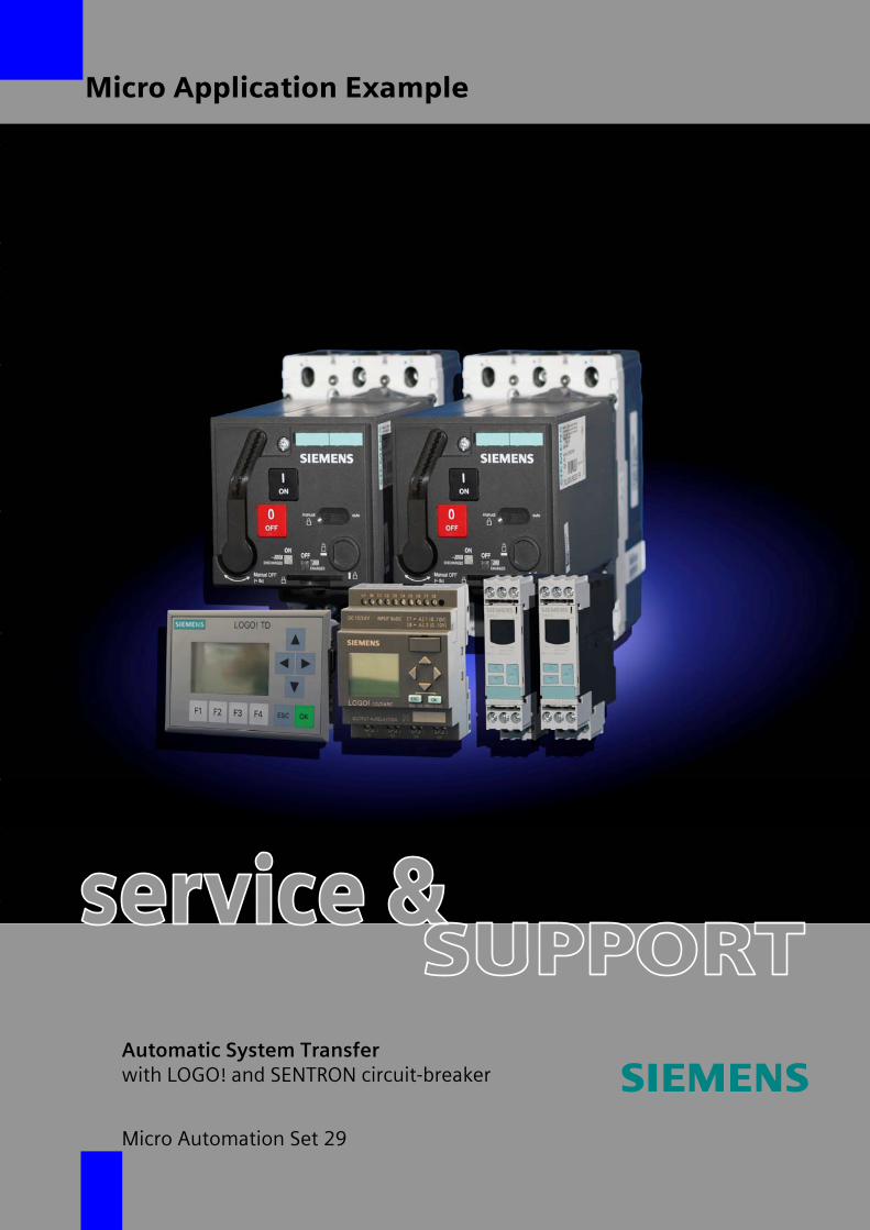
Micro Application Example
Automatic System Transfer with LOGO! and SENTRON circuit-breaker
Micro Automation Set 29
Table of Contents
Micro Automation Set 29 Entry-ID 27074055
V2.0 22.08.2008 2/74
Cop
yrig
ht ©
Sie
men
s A
G 2
008
All
right
s re
serv
ed
Set
29_D
ocTe
ch_V
2d0_
en.d
oc
Note The Micro Automation Sets are not binding and do not claim to be complete regarding their configuration, equipment and any eventuality. The Micro Automation Sets do not represent customer-specific solutions. They are only intended to provide support for typical applications. You are responsible for ensuring that the described products are used correctly. These Micro Automation Sets do not relieve you of the responsibility of safely and professionally using, installing, operating and servicing equipment. When using these Micro Automation Sets, you recognize that Siemens cannot be made liable for any damage/claims beyond the liability clause described. We reserve the right to make changes to these Micro Automation Sets at any time without prior notice. If there are any deviations between the recommendations provided in these Micro Automation Sets and other Siemens publications – e.g. Catalogs – the contents of the other documents have priority.
Warranty, Liability and Support We do not accept any liability for the information contained in this document.
Any claims against us – based on whatever legal reason – resulting from the use of the examples, information, programs, engineering and performance data etc., described in this Micro Automation Set shall be excluded. Such an exclusion shall not apply in the case of mandatory liability, e.g. under the German Product Liability Act (“Produkthaftungsgesetz”), in case of intent, gross negligence, or injury of life, body or health, guarantee for the quality of a product, fraudulent concealment of a deficiency or breach of a condition which goes to the root of the contract (“wesentliche Vertragspflichten”). However, claims arising from a breach of a condition which goes to the root of the contract shall be limited to the foreseeable damage which is intrinsic to the contract, unless caused by intent or gross negligence or based on mandatory liability for injury of life, body or health. The above provisions does not imply a change in the burden of proof to your detriment.
Copyright© 2008 Siemens IA/ DT. It is not permissible to transfer or copy these Micro Automation Sets or excerpts of them without first having prior authorization from Siemens A&D in writing.
Table of Contents
Micro Automation Set 29 Entry-ID 27074055
V2.0 22.08.2008 3/74
Cop
yrig
ht ©
Sie
men
s A
G 2
008
All
right
s re
serv
ed
Set
29_D
ocTe
ch_V
2d0_
en.d
oc
Preface Micro Automation Sets are functional and tested automation configurations based on A&D standard products for easy, fast and inexpensive implementation of automation tasks for small-scale automation. Each of the available Micro Automatic Sets covers a frequently occurring subtask of a typical customer problem in the low-end performance level.
The sets help you to obtain answers with regard to required products and the question of how they function when combined.
However, depending on the system requirements, a variety of other components (e.g. other CPUs, power supplies, etc.) can be used to implement the functionality on which this set is based. For these components, please refer to the corresponding SIEMENS A&D catalogs.
The Micro Automation Sets are also available by clicking the following link:
http://www.siemens.de/microset
Table of Contents
Micro Automation Set 29 Entry-ID 27074055
V2.0 22.08.2008 4/74
Cop
yrig
ht ©
Sie
men
s A
G 2
008
All
right
s re
serv
ed
Set
29_D
ocTe
ch_V
2d0_
en.d
oc
Table of Contents
Table of Contents ......................................................................................................... 4
1 Application Areas and Usage ........................................................................ 6 1.1 Automation Task............................................................................................... 6 1.2 Automation solution – Set 29............................................................................ 7 1.2.1 Block diagram ................................................................................................... 7 1.3 Application areas ............................................................................................ 10 1.4 Benefits........................................................................................................... 10
2 Wiring Diagrams ........................................................................................... 11 2.1 Wiring diagram: 230V power supply ............................................................... 11 2.2 Wiring diagram: Logic module and monitoring relay....................................... 12 2.2.1 Operating via external switches and push buttons ......................................... 12 2.2.2 Operation via the new LOGO! text display unit............................................... 13 2.3 Wiring diagram: Circuit-breaker ...................................................................... 14
3 Hardware and Software Components......................................................... 15 3.1 System transfer............................................................................................... 15
4 Function Principle ........................................................................................ 17 4.1 Motorized circuit-breaker ................................................................................ 17 4.2 SIRIUS monitoring relay ................................................................................. 20 4.3 Overview of the operating functions ............................................................... 21 4.3.1 Operating via external switches and push buttons ......................................... 21 4.3.2 Operation via the new LOGO! text display ..................................................... 23 4.4 Operating modes ............................................................................................ 25 4.4.1 Automatic mode.............................................................................................. 25 4.4.2 Manual operation ............................................................................................ 29 4.4.3 Service operation............................................................................................ 33 4.4.4 Power management........................................................................................ 34 4.5 Event and fault messages .............................................................................. 35 4.5.1 Event messages ............................................................................................. 35 4.5.2 Fault messages .............................................................................................. 36 4.6 Auxiliary contacts............................................................................................ 37 4.7 Controls of the circuit-breaker......................................................................... 38 4.8 Software concept ............................................................................................ 39 4.8.1 Criteria (Automatic)......................................................................................... 40 4.8.2 Machine safety................................................................................................ 40 4.8.3 Action.............................................................................................................. 40 4.8.4 Action monitoring ............................................................................................ 40 4.8.5 Manual monitoring .......................................................................................... 40
5 Configuration of the Startup Software........................................................ 41 5.1 Preliminary remarks........................................................................................ 41
Table of Contents
Micro Automation Set 29 Entry-ID 27074055
V2.0 22.08.2008 5/74
Cop
yrig
ht ©
Sie
men
s A
G 2
008
All
right
s re
serv
ed
Set
29_D
ocTe
ch_V
2d0_
en.d
oc
5.2 Download of the startup code ......................................................................... 41 5.3 Configuring components................................................................................. 41 5.3.1 Installing and wiring the hardware .................................................................. 42 5.3.2 Network supply and generator supply ............................................................ 43 5.4 Preparations ................................................................................................... 44
6 Live-Demo ..................................................................................................... 47 6.1 Overview of all scenarios................................................................................ 47 6.1.1 AUTO: Automatic system transfer .................................................................. 48 6.1.2 AUTO: Short-term power system failure......................................................... 53 6.1.3 AUTO: An error occurs during the automatic system transfer ........................ 55 6.1.4 AUTO: Function test of the automatic system transfer ................................... 60 6.1.5 AUTO: Overload/short-circuit test................................................................... 64 6.1.6 SERVICE: Service mode ................................................................................ 66 6.1.7 SERVICE: Power management...................................................................... 68 6.1.8 MANUAL: Manual mode circuit-breaker NET ................................................. 69 6.1.9 MANUAL: Manual mode circuit-breaker GEN ................................................ 70 6.1.10 MANUAL: Manual load and generator request............................................... 71 6.1.11 SERVICE: Operating the circuit-breakers directly via the controls ................. 72
7 Technical Data .............................................................................................. 74 7.1 LOGO! ............................................................................................................ 74 7.2 SENTRON ...................................................................................................... 74 7.3 SIRIUS............................................................................................................ 74
Application Areas and Usage
Micro Automation Set 29 Entry-ID 27074055
V2.0 22.08.2008 6/74
Cop
yrig
ht ©
Sie
men
s A
G 2
008
All
right
s re
serv
ed
Set
29_D
ocTe
ch_V
2d0_
en.d
oc
1 Application Areas and Usage
1.1 Automation Task
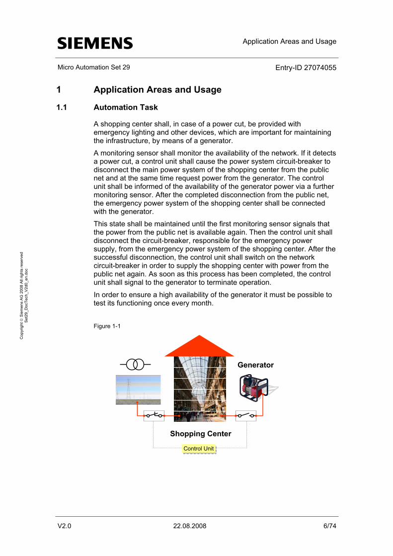
A shopping center shall, in case of a power cut, be provided with emergency lighting and other devices, which are important for maintaining the infrastructure, by means of a generator.
A monitoring sensor shall monitor the availability of the network. If it detects a power cut, a control unit shall cause the power system circuit-breaker to disconnect the main power system of the shopping center from the public net and at the same time request power from the generator. The control unit shall be informed of the availability of the generator power via a further monitoring sensor. After the completed disconnection from the public net, the emergency power system of the shopping center shall be connected with the generator.
This state shall be maintained until the first monitoring sensor signals that the power from the public net is available again. Then the control unit shall disconnect the circuit-breaker, responsible for the emergency power supply, from the emergency power system of the shopping center. After the successful disconnection, the control unit shall switch on the network circuit-breaker in order to supply the shopping center with power from the public net again. As soon as this process has been completed, the control unit shall signal to the generator to terminate operation.
In order to ensure a high availability of the generator it must be possible to test its functioning once every month. Figure 1-1
Generator
Shopping Center
Control UnitControl Unit
Application Areas and Usage
Micro Automation Set 29 Entry-ID 27074055
V2.0 22.08.2008 7/74
Cop
yrig
ht ©
Sie
men
s A
G 2
008
All
right
s re
serv
ed
Set
29_D
ocTe
ch_V
2d0_
en.d
oc
1.2 Automation solution – Set 29
One compact circuit-breaker each of type VL 160N connects the shopping center with the public net or the emergency power system respectively.
Using the SIRIUS monitoring relays, the availability of the 3 phases of the public net and the emergency power system are monitored.
The LOGO! logic module disconnects the circuit-breaker from the public net if the SIRIUS monitoring relay detects a phase error or a failure and requests the generator to be switched on.
If the availability of the generator power system is confirmed via the SIRIUS monitoring relay, the LOGO! logic module connects the circuit-breaker to the generator power system.
If the SIRIUS monitoring relay signals that the public net is available again, the LOGO! logic module transfers back to the public net and switches the generator off.
For maintenance purposes it can be switched to manual mode. The circuit-breaker can be switched either to the public net or the generator power system and be switched on and off by means of the direct button.
1.2.1 Block diagram
2 solutions are offered.
Version 1: Operation via external switches and push buttons. Ideal with the new LOGO! text display unit as an additional display.
• Project: see table 5-1; no.1
Version 2: Operation merely via the new LOGO! text display
• Project: table 5-1; no.2
Application Areas and Usage
Micro Automation Set 29 Entry-ID 27074055
V2.0 22.08.2008 8/74
Cop
yrig
ht ©
Sie
men
s A
G 2
008
All
right
s re
serv
ed
Set
29_D
ocTe
ch_V
2d0_
en.d
oc
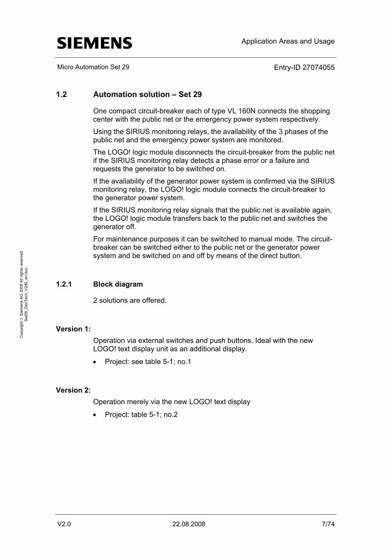
Operating via external switches and push buttons The figure shows the block diagram with external switches and push buttons.
Figure 1-2
Net
Circuit-breaker VL160 (Net) Circuit-breaker VL160 (Generator)2
LOGO! Expansion module5
4
Generator
1 2
5 6
G
1Push-button7Knob switch6
7
I II0
I II0
4
s
13NO 21NC 31NC 21NC A1+DC 24V
14NO 22NC 32NC 44NO A2-
3
LOGO! Basic module
SIRIUS Contactor34
SIRIUS Net monitoring module8
8
9
Optional LOGO! Text display unit9
Application Areas and Usage
Micro Automation Set 29 Entry-ID 27074055
V2.0 22.08.2008 9/74
Cop
yrig
ht ©
Sie
men
s A
G 2
008
All
right
s re
serv
ed
Set
29_D
ocTe
ch_V
2d0_
en.d
oc
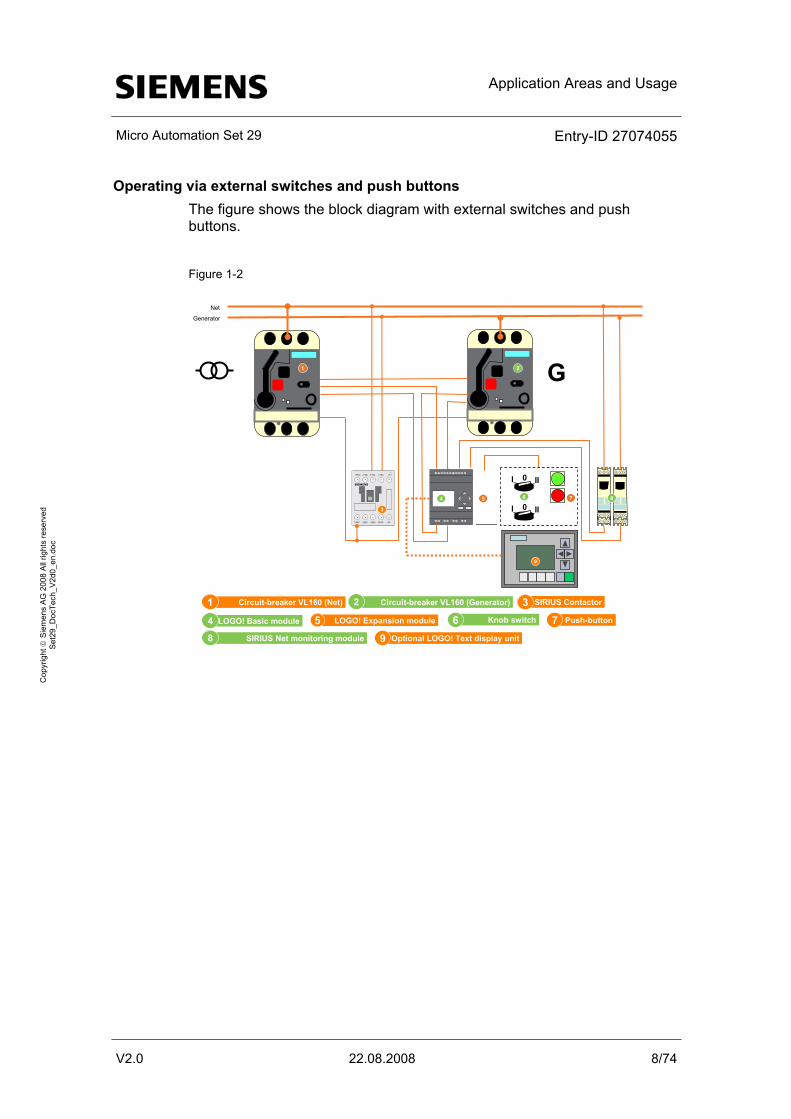
Operating via the new LOGO! text display The figure shows the block diagram with the LOGO! text display unit.
Figure 1-3
Net
Circuit-breaker VL160 (Netz) Circuit-breaker VL160 (Generator)2
LOGO! Expansion module5
4
Generator
1 2
5
G
1
LOGO! TD6
4
s
13NO 21NC 31NC 21NC A1+
DC 24V
14NO 22NC 32NC 44NO A2-
3
LOGO! Basic module
SIRIUS Contactor3
4
SIRIUS Net monitoring relay7
76
Application Areas and Usage
Micro Automation Set 29 Entry-ID 27074055
V2.0 22.08.2008 10/74
Cop
yrig
ht ©
Sie
men
s A
G 2
008
All
right
s re
serv
ed
Set
29_D
ocTe
ch_V
2d0_
en.d
oc
1.3 Application areas
Industry • Production lines for continuous production
• Engine rooms for ships
• Important additional equipment for thermal power plants
Infrastructure • Docks and railroad systems
• Airport lighting
Building technologies • Operating theaters in hospitals
• Computer rooms (banks, insurance companies, etc.)
• Lighting systems for shopping centers
• Public buildings
1.4 Benefits
• Network monitoring is safely and reliably handled by the SIRIUS monitoring relay 3UG4
• The system transfer process is controlled cost-effectively by the LOGO! logic module
• The high transfer requirement is realized by SENTRON motorized compact circuit-breakers.
• The automatic system transfer ensures a safe power supply during power failure
• Cost reduction – due to automatic system transfer during power failure and the automatic reset upon a restored network, the service personnel need not interfere
• Preselectable power management
• Load shedding during system transfer to the emergency power system
Wiring Diagrams
Micro Automation Set 29 Entry-ID 27074055
V2.0 22.08.2008 11/74
Cop
yrig
ht ©
Sie
men
s A
G 2
008
All
right
s re
serv
ed
Set
29_D
ocTe
ch_V
2d0_
en.d
oc
2 Wiring Diagrams
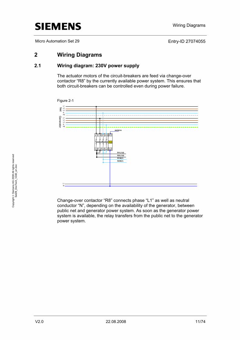
2.1 Wiring diagram: 230V power supply
The actuator motors of the circuit-breakers are feed via change-over contactor “R8” by the currently available power system. This ensures that both circuit-breakers can be controlled even during power failure.
Figure 2-1
L+M
21 13 31 43
22 14 32 44
R8
A1
A2R1\L1(4)R2\L1(4)R1\N(1)R2\N(1)
A42\K14
L1L2L3NPE
L1L2L3NPE
Net
Generator
Change-over contactor “R8” connects phase “L1” as well as neutral conductor “N”, depending on the availability of the generator, between public net and generator power system. As soon as the generator power system is available, the relay transfers from the public net to the generator power system.
Wiring Diagrams
Micro Automation Set 29 Entry-ID 27074055
V2.0 22.08.2008 12/74
Cop
yrig
ht ©
Sie
men
s A
G 2
008
All
right
s re
serv
ed
Set
29_D
ocTe
ch_V
2d0_
en.d
oc
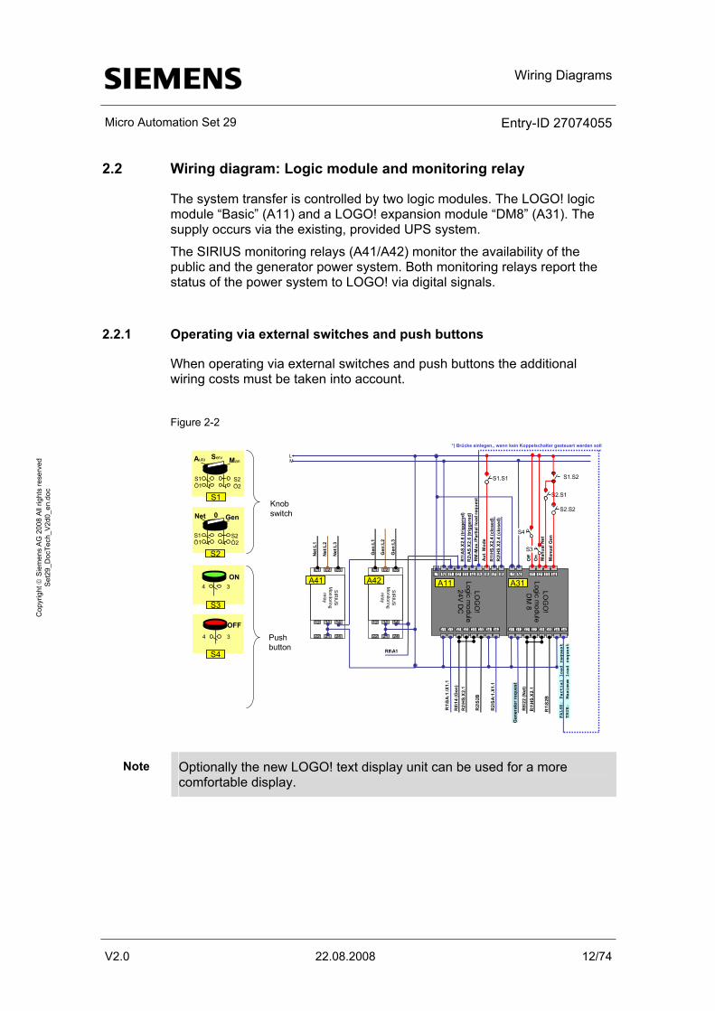
2.2 Wiring diagram: Logic module and monitoring relay
The system transfer is controlled by two logic modules. The LOGO! logic module “Basic” (A11) and a LOGO! expansion module “DM8” (A31). The supply occurs via the existing, provided UPS system.
The SIRIUS monitoring relays (A41/A42) monitor the availability of the public and the generator power system. Both monitoring relays report the status of the power system to LOGO! via digital signals.
2.2.1 Operating via external switches and push buttons
When operating via external switches and push buttons the additional wiring costs must be taken into account.
Figure 2-2
R8\
14 (G
en)
LOG
O!
Logicm
odule24V D
C
L1 I1N I3 I6I2 I5 I7Î4 I8
Q11 Q31Q12 Q22Q21 Q32Q41Q42
LOG
O!
Logicm
oduleD
M 8
L1 I1N I3I2 Î4
Q11 Q31Q12 Q22Q21 Q32Q41Q42
L+M
L1 L2 L3
22 2421
12 1411
SIR
IUS
Monitoringrelay
R2\
S2B
R1\
AS.
X2.
6 (tr
igge
red)
R1\
HS.
X2.
4 (c
lose
d)
A11 A31A41
Net
:L1
Net
:L2
Net
:L3
R8\
22 (N
et)
R1\
S2B
R2\
HS.
X2.
4 (c
lose
d)
L1 L2 L3
22 2421
12 1411
SIR
IUS
Monitoringrelay
A42
Gen
:L1
Gen
:L2
Gen
:L3
R8\A1
RM
-Max
./Par
tiall
oad
requ
est
Auto ManServ
S1Ö1
S2Ö2
S1
Net Gen0
S1Ö1
S2
S2Ö2
S2.S2
R2\
HS.
X2.
1
4
S3
3
S4
Knobswitch
Push button
R1\
SA:
1.\X
1.1
R1\
HS.
X2.
1
Gen
erat
or r
eque
st
R2\
SA
:1.X
1.1
R2\
AS.
X2.
6 (tr
igge
red)
S1.S1A
ut. M
ode
Off
S3
On
S2.S1
Man
ual N
et
Man
ual G
en
ON
OFF
S1.S2
4 3
S4
FALSE: Partial load request
TRUE: Maximum load request
*) Brücke einlegen,, wenn kein Koppelschalter gesteuert werden soll
Note Optionally the new LOGO! text display unit can be used for a more comfortable display.
Wiring Diagrams
Micro Automation Set 29 Entry-ID 27074055
V2.0 22.08.2008 13/74
Cop
yrig
ht ©
Sie
men
s A
G 2
008
All
right
s re
serv
ed
Set
29_D
ocTe
ch_V
2d0_
en.d
oc
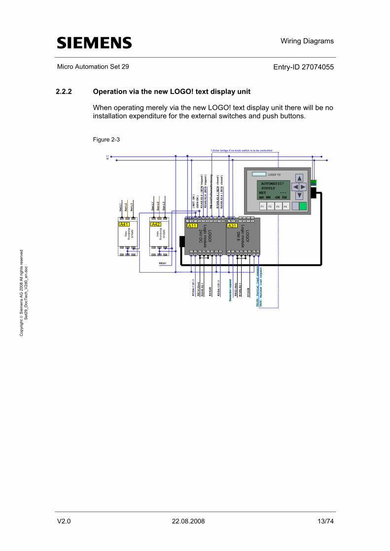
2.2.2 Operation via the new LOGO! text display unit
When operating merely via the new LOGO! text display unit there will be no installation expenditure for the external switches and push buttons.
Figure 2-3
s LOGO! TD
F1 F3F2 F4
R8\
14 (G
en)
LOG
O!
Logic module
24V DC
L1 I1N I3 I6I2 I5 I7Î4 I8
Q11 Q31Q12 Q22Q21 Q32Q41Q42
LOG
O!
Logic module
DM
8
L1 I1N I3I2 Î4
Q11 Q31Q12 Q22Q21 Q32Q41Q42
L+M
L1 L2 L3
22 2421
12 1411
SIR
IUS
Monitoringrelay
R2\
S2B
R1\
AS.
X2.6
( B
CN:
trip
ped
)
R1\
HS.
X2.4
( B
CN:
clo
sed
)
A11 A31A41
Net
:L1
Net
:L2
Net
:L3
R8\
22 (N
et)
R1\
S2B
R2\
HS.
X2.4
( B
CG
: clo
sed
)L1 L2 L3
22 2421
12 1411
SIR
IUS
Monitoringrelay
A42
Gen
:L1
Gen
:L2
Gen
:L3
R8\A1
R2\
HS.
X2.1
R1\
SA
:1.\X
1.1
R1\
HS.
X2.1
Gen
erat
or r
eque
st
R2\
SA
:1.X
1.1
R2\
AS.
X2.6
(B
CG
: trip
ped
)
( NET
: OK
)(G
EN:O
K )
AUTOMATIC! SUPPLY NET ---AM NM GM SM
FALSE:
Partial
load
request
TRUE: M
aximum
load re
quest
RM
-Vol
l/Tei
llast
anfo
rder
ung
*) Enter bridge if no knob switch is to be controlled
Wiring Diagrams
Micro Automation Set 29 Entry-ID 27074055
V2.0 22.08.2008 14/74
Cop
yrig
ht ©
Sie
men
s A
G 2
008
All
right
s re
serv
ed
Set
29_D
ocTe
ch_V
2d0_
en.d
oc
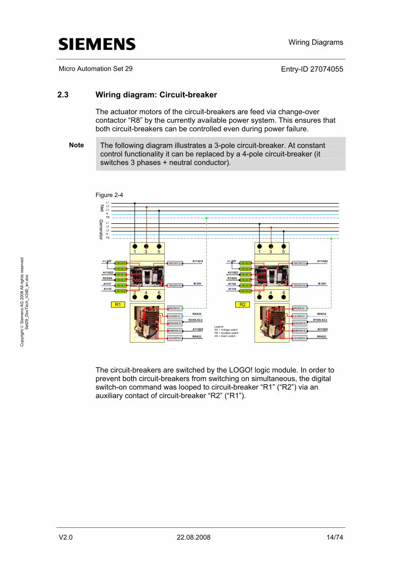
2.3 Wiring diagram: Circuit-breaker
The actuator motors of the circuit-breakers are feed via change-over contactor “R8” by the currently available power system. This ensures that both circuit-breakers can be controlled even during power failure.
Note The following diagram illustrates a 3-pole circuit-breaker. At constant control functionality it can be replaced by a 4-pole circuit-breaker (it switches 3 phases + neutral conductor).
Figure 2-4
R2\HS.X2.2
A11\Q32Legend:SA = Voltage switchHS = Auxiliary switchAS = Alarm switchR8\K22
L1L2L3NPE
L1L2L3NPE
Net
Generator
1
2
3
4
5
6
HS.X2.1
HS.X2.2
HS.X2.3
HS.X2.4
AS.X2.5
AS.X2.6
SA:1(X1.1)
SA:2(X1.2)
R1PE(X20.5)
S2A(X20.2)
L2-(X20.1)
L2+(X20.4)
S2B(X20.3)
M 24V
R8\K32
A11\Q12
A11\Q22
R2\S2A
A11\I7
L+ 24V
A11\I3
R1\HS.X2.2
A31\Q32
R8\K22
1
2
3
4
5
6
HS.X2.1
HS.X2.2
HS.X2.3
HS.X2.4
AS.X2.5
AS.X2.6
SA:1(X1.1)
SA:2(X1.2)
R2PE(X20.5)
S2A(X20.2)
L2-(X20.1)
L2+(X20.4)
S2B(X20.3)
M 24V
R8\K32
A11\Q42
A31\Q22
R1\S2A
A11\I8
L+ 24V
A11\I4
The circuit-breakers are switched by the LOGO! logic module. In order to prevent both circuit-breakers from switching on simultaneous, the digital switch-on command was looped to circuit-breaker “R1” (“R2”) via an auxiliary contact of circuit-breaker “R2” (“R1”).
Hardware and Software Components
Micro Automation Set 29 Entry-ID 27074055
V2.0 22.08.2008 15/74
Cop
yrig
ht ©
Sie
men
s A
G 2
008
All
right
s re
serv
ed
Set
29_D
ocTe
ch_V
2d0_
en.d
oc
3 Hardware and Software Components
3.1 System transfer
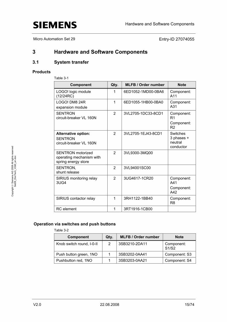
Products Table 3-1
Component Qty. MLFB / Order number Note
LOGO! logic module (12/24RC)
1 6ED1052-1MD00-0BA6 Component: A11
LOGO! DM8 24R expansion module
1 6ED1055-1HB00-0BA0 Component: A31
SENTRON circuit-breaker VL 160N
2 3VL2705-1DC33-8CD1 Component: R1 Component: R2
Alternative option: SENTRON circuit-breaker VL 160N
2 3VL2705-1EJ43-8CD1 Switches 3 phases + neutral conductor
SENTRON motorized operating mechanism with spring energy store
2 3VL9300-3MQ00
SENTRON, shunt release
2 3VL94001SC00
SIRIUS monitoring relay 3UG4
2 3UG4617-1CR20 Component: A41 Component: A42
SIRIUS contactor relay 1 3RH1122-1BB40 Component: R8
RC element 1 3RT1916-1CB00
Operation via switches and push buttons Table 3-2
Component Qty. MLFB / Order number Note
Knob switch round, I-0-II 2 3SB3210-2DA11 Component: S1/S2
Push button green, 1NO 1 3SB3202-0AA41 Component: S3 Pushbutton red, 1NO 1 3SB3203-0AA21 Component: S4
Hardware and Software Components
Micro Automation Set 29 Entry-ID 27074055
V2.0 22.08.2008 16/74
Cop
yrig
ht ©
Sie
men
s A
G 2
008
All
right
s re
serv
ed
Set
29_D
ocTe
ch_V
2d0_
en.d
oc
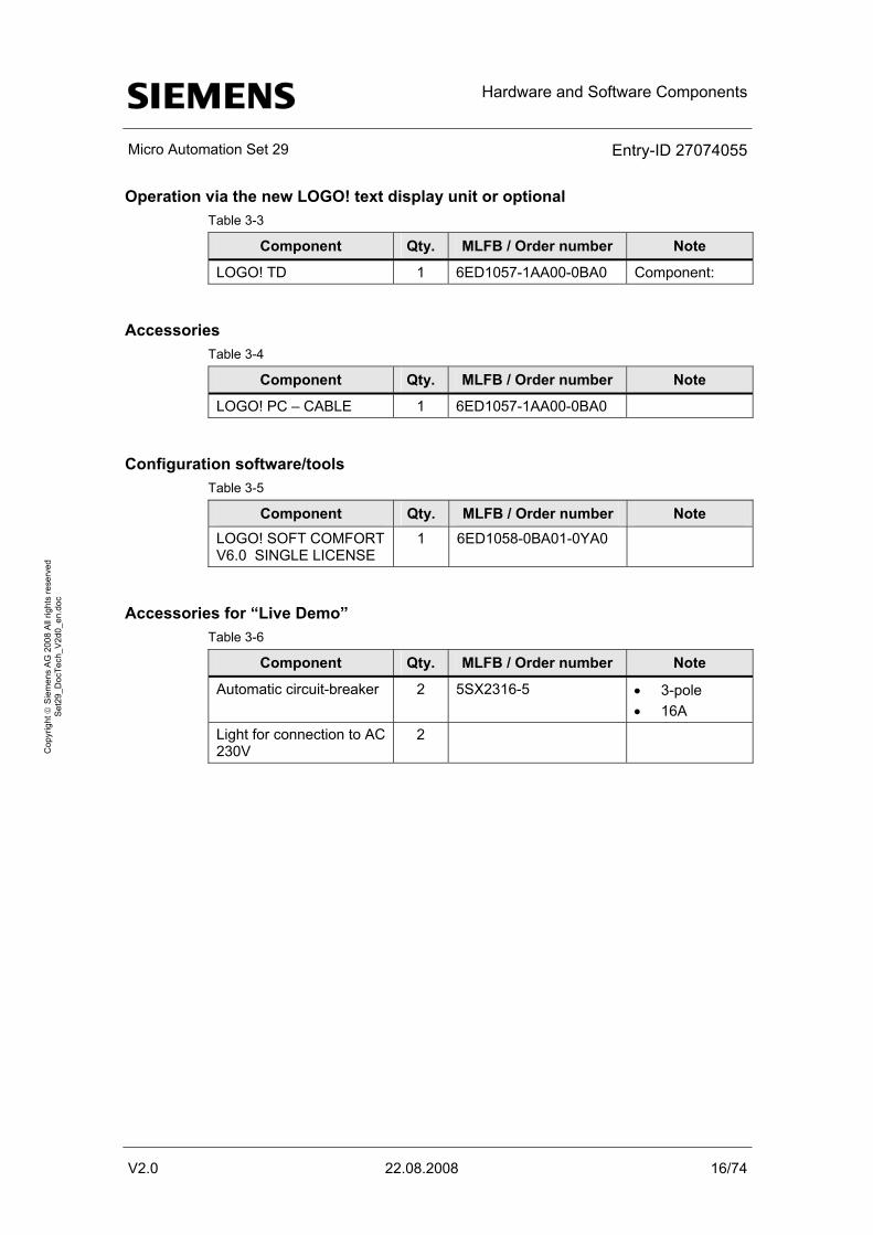
Operation via the new LOGO! text display unit or optional Table 3-3
Component Qty. MLFB / Order number Note
LOGO! TD 1 6ED1057-1AA00-0BA0 Component:
Accessories Table 3-4
Component Qty. MLFB / Order number Note
LOGO! PC – CABLE 1 6ED1057-1AA00-0BA0
Configuration software/tools Table 3-5
Component Qty. MLFB / Order number Note LOGO! SOFT COMFORT V6.0 SINGLE LICENSE
1 6ED1058-0BA01-0YA0
Accessories for “Live Demo” Table 3-6
Component Qty. MLFB / Order number Note
Automatic circuit-breaker 2 5SX2316-5 • 3-pole • 16A
Light for connection to AC 230V
2
Function Principle
Micro Automation Set 29 Entry-ID 27074055
V2.0 22.08.2008 17/74
Cop
yrig
ht ©
Sie
men
s A
G 2
008
All
right
s re
serv
ed
Set
29_D
ocTe
ch_V
2d0_
en.d
oc
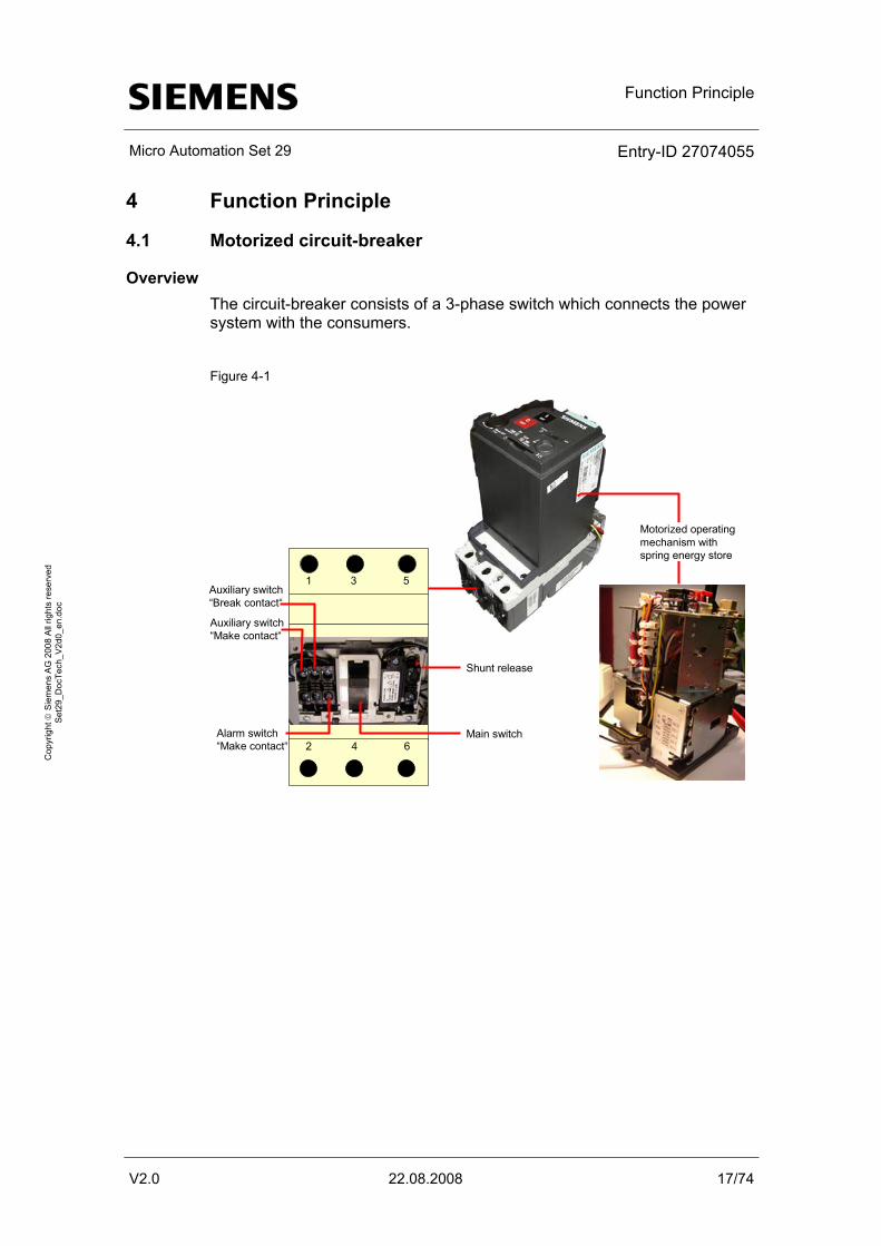
4 Function Principle
4.1 Motorized circuit-breaker
Overview The circuit-breaker consists of a 3-phase switch which connects the power system with the consumers.
Figure 4-1
1
2
3
4
5
6
Shunt release
Motorized operating mechanism with spring energy store
Auxiliary switch“Make contact“
Auxiliary switch“Break contact“
Alarm switch“Make contact“
Main switch
Function Principle
Micro Automation Set 29 Entry-ID 27074055
V2.0 22.08.2008 18/74
Cop
yrig
ht ©
Sie
men
s A
G 2
008
All
right
s re
serv
ed
Set
29_D
ocTe
ch_V
2d0_
en.d
oc
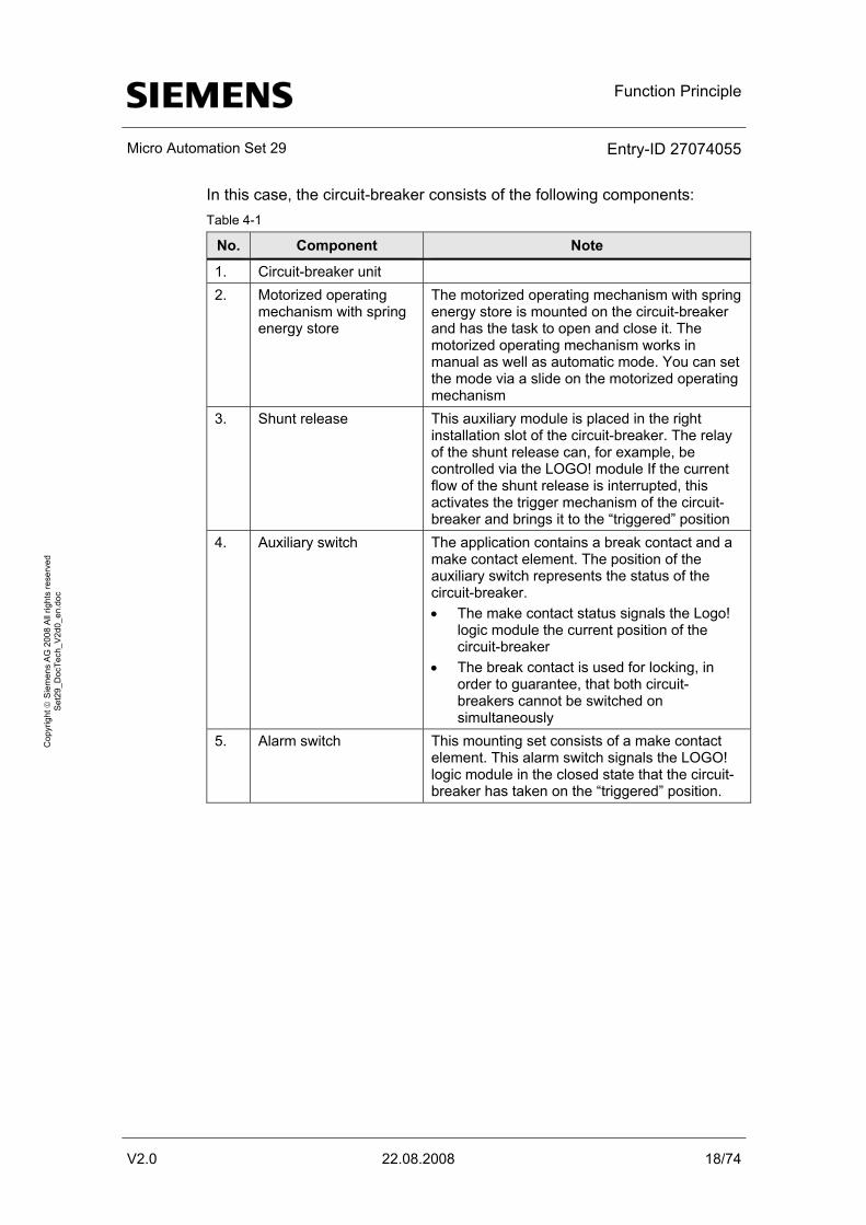
In this case, the circuit-breaker consists of the following components: Table 4-1
No. Component Note
1. Circuit-breaker unit 2. Motorized operating
mechanism with spring energy store
The motorized operating mechanism with spring energy store is mounted on the circuit-breaker and has the task to open and close it. The motorized operating mechanism works in manual as well as automatic mode. You can set the mode via a slide on the motorized operating mechanism
3. Shunt release This auxiliary module is placed in the right installation slot of the circuit-breaker. The relay of the shunt release can, for example, be controlled via the LOGO! module If the current flow of the shunt release is interrupted, this activates the trigger mechanism of the circuit-breaker and brings it to the “triggered” position
4. Auxiliary switch The application contains a break contact and a make contact element. The position of the auxiliary switch represents the status of the circuit-breaker. • The make contact status signals the Logo!
logic module the current position of the circuit-breaker
• The break contact is used for locking, in order to guarantee, that both circuit-breakers cannot be switched on simultaneously
5. Alarm switch This mounting set consists of a make contact element. This alarm switch signals the LOGO! logic module in the closed state that the circuit-breaker has taken on the “triggered” position.
Function Principle
Micro Automation Set 29 Entry-ID 27074055
V2.0 22.08.2008 19/74
Cop
yrig
ht ©
Sie
men
s A
G 2
008
All
right
s re
serv
ed
Set
29_D
ocTe
ch_V
2d0_
en.d
oc
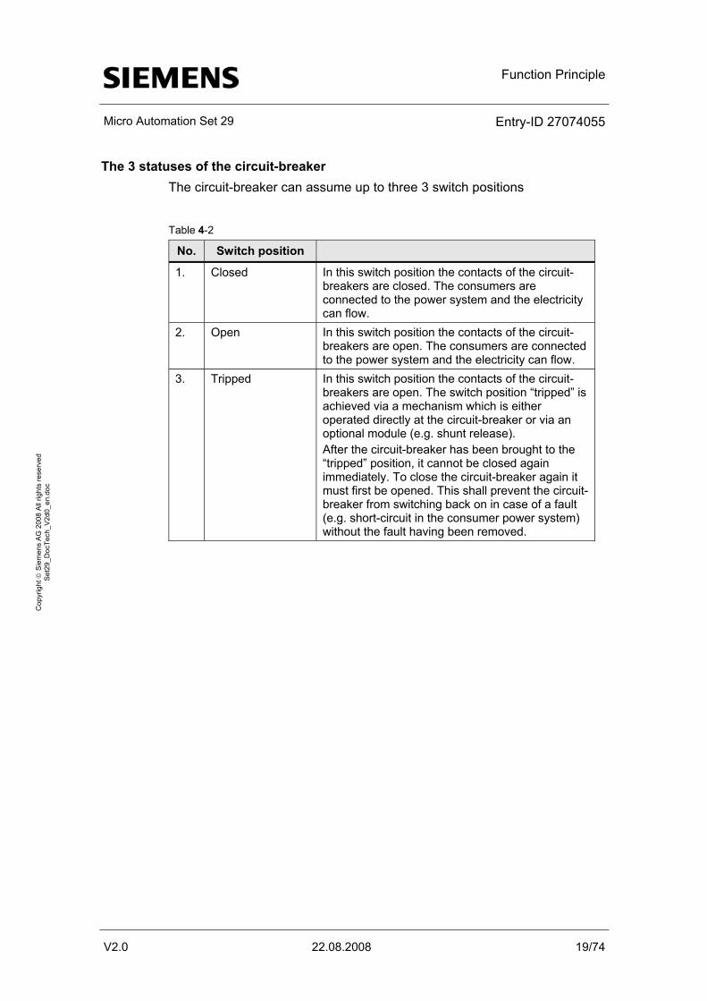
The 3 statuses of the circuit-breaker The circuit-breaker can assume up to three 3 switch positions
Table 4-2
No. Switch position
1. Closed In this switch position the contacts of the circuit-breakers are closed. The consumers are connected to the power system and the electricity can flow.
2. Open In this switch position the contacts of the circuit-breakers are open. The consumers are connected to the power system and the electricity can flow.
3. Tripped In this switch position the contacts of the circuit-breakers are open. The switch position “tripped” is achieved via a mechanism which is either operated directly at the circuit-breaker or via an optional module (e.g. shunt release). After the circuit-breaker has been brought to the “tripped” position, it cannot be closed again immediately. To close the circuit-breaker again it must first be opened. This shall prevent the circuit-breaker from switching back on in case of a fault (e.g. short-circuit in the consumer power system) without the fault having been removed.
Function Principle
Micro Automation Set 29 Entry-ID 27074055
V2.0 22.08.2008 20/74
Cop
yrig
ht ©
Sie
men
s A
G 2
008
All
right
s re
serv
ed
Set
29_D
ocTe
ch_V
2d0_
en.d
oc
4.2 SIRIUS monitoring relay
Monitoring relay 3UG4617 monitors the following states:
• Phase sequence
• Phase failure of one of the phases
• Falling below and exceeding a set voltage
• Exceeding a set asymmetry value
• Difference between the largest and the smallest phase voltage in relation to the largest phase voltage (Ux-y max - Ux-y min) / Ux-y max, in a three-phase power system.
If the correct phase sequence is connected to terminals L1-L2-L3, relay A41 or A42 picks up. This is indicated by a relay icon in the display. If the phase sequence is wrong it does not pick up. No fault display appears on the screen, there will only be no relay icon !
If the monitored voltage (Ux-y) is larger than the set lower voltage value (U|) and smaller than the set upper voltage value (Ux), i.e. it is within the voltage limits, and the network voltage asymmetry (Asy) is smaller than the set value, relay A41 or A42 (contact 11-12-14) picks up approx. 50ms after the reaction of A41 or A42. The display at 3UG4617 shows the current phase-to-phase voltage between L1 and L2.
The following network errors are displayed as diagnosis message with blinking icons on the display:
• Phase failure (3UG4618 or failure of the N-conductor). Symmetrical (all three phase/star voltages simultaneously)
• Asymmetrically (only one phase/star voltage) falling short of or exceeding of the voltage value set in the menu. Exceeding the asymmetry which was set in the menu.
During a phase failure the relay A41 or A42 drops out. For the error cases:
• Falling short of voltage value
• Exceeding voltage value
• Asymmetrical exceeding
relay A41 or A42 drops out after the set error delay time (Del).
Function Principle
Micro Automation Set 29 Entry-ID 27074055
V2.0 22.08.2008 21/74
Cop
yrig
ht ©
Sie
men
s A
G 2
008
All
right
s re
serv
ed
Set
29_D
ocTe
ch_V
2d0_
en.d
oc
4.3 Overview of the operating functions
4.3.1 Operating via external switches and push buttons
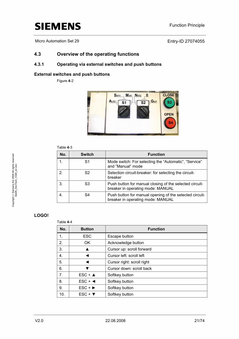
External switches and push buttons Figure 4-2
S1 S2
S4
S3Auto
Serv Man Netz 0Gen
CLOSE
OPEN
Table 4-3
No. Switch Function
1. S1 Mode switch: For selecting the “Automatic”, “Service” and ”Manual” mode
2. S2 Selection circuit-breaker: for selecting the circuit-breaker
3. S3 Push button for manual closing of the selected circuit-breaker in operating mode: MANUAL
4. S4 Push button for manual opening of the selected circuit-breaker in operating mode: MANUAL
LOGO! Table 4-4
No. Button Function
1. ESC Escape button 2. OK Acknowledge button 3. ▲ Cursor up: scroll forward 4. ◄ Cursor left: scroll left 5. ◄ Cursor right: scroll right 6. ▼ Cursor down: scroll back 7. ESC + ▲ Softkey button 8. ESC + ◄ Softkey button 9. ESC + ► Softkey button 10. ESC + ▼ Softkey button
Function Principle
Micro Automation Set 29 Entry-ID 27074055
V2.0 22.08.2008 22/74
Cop
yrig
ht ©
Sie
men
s A
G 2
008
All
right
s re
serv
ed
Set
29_D
ocTe
ch_V
2d0_
en.d
oc
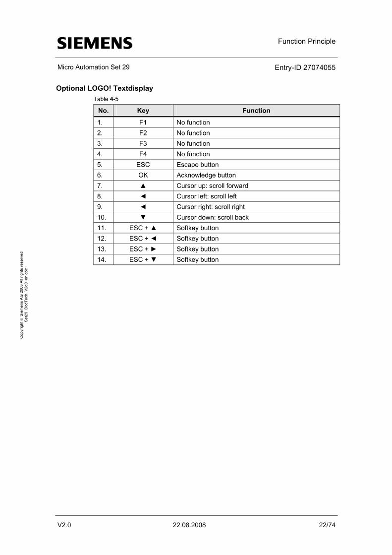
Optional LOGO! Textdisplay Table 4-5
No. Key Function
1. F1 No function 2. F2 No function 3. F3 No function 4. F4 No function 5. ESC Escape button 6. OK Acknowledge button 7. ▲ Cursor up: scroll forward 8. ◄ Cursor left: scroll left 9. ◄ Cursor right: scroll right 10. ▼ Cursor down: scroll back 11. ESC + ▲ Softkey button 12. ESC + ◄ Softkey button 13. ESC + ► Softkey button 14. ESC + ▼ Softkey button
Function Principle
Micro Automation Set 29 Entry-ID 27074055
V2.0 22.08.2008 23/74
Cop
yrig
ht ©
Sie
men
s A
G 2
008
All
right
s re
serv
ed
Set
29_D
ocTe
ch_V
2d0_
en.d
oc
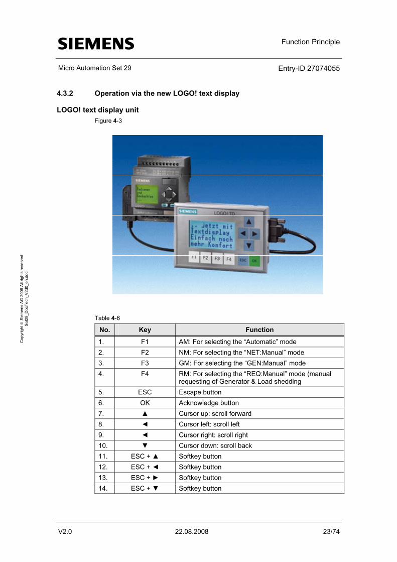
4.3.2 Operation via the new LOGO! text display
LOGO! text display unit Figure 4-3
Table 4-6
No. Key Function
1. F1 AM: For selecting the “Automatic” mode 2. F2 NM: For selecting the “NET:Manual” mode 3. F3 GM: For selecting the “GEN:Manual” mode 4. F4 RM: For selecting the “REQ:Manual” mode (manual
requesting of Generator & Load shedding 5. ESC Escape button 6. OK Acknowledge button 7. ▲ Cursor up: scroll forward 8. ◄ Cursor left: scroll left 9. ◄ Cursor right: scroll right 10. ▼ Cursor down: scroll back 11. ESC + ▲ Softkey button 12. ESC + ◄ Softkey button 13. ESC + ► Softkey button 14. ESC + ▼ Softkey button
Function Principle
Micro Automation Set 29 Entry-ID 27074055
V2.0 22.08.2008 24/74
Cop
yrig
ht ©
Sie
men
s A
G 2
008
All
right
s re
serv
ed
Set
29_D
ocTe
ch_V
2d0_
en.d
oc
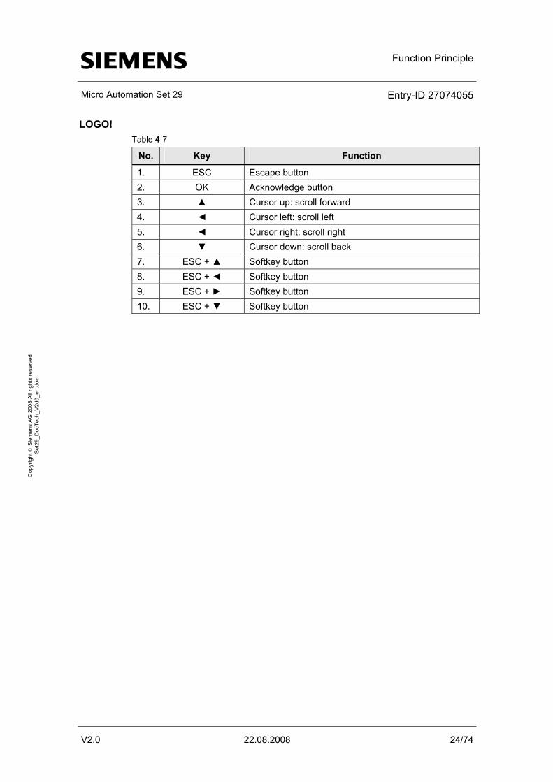
LOGO! Table 4-7
No. Key Function
1. ESC Escape button 2. OK Acknowledge button 3. ▲ Cursor up: scroll forward 4. ◄ Cursor left: scroll left 5. ◄ Cursor right: scroll right 6. ▼ Cursor down: scroll back 7. ESC + ▲ Softkey button 8. ESC + ◄ Softkey button 9. ESC + ► Softkey button 10. ESC + ▼ Softkey button
Function Principle
Micro Automation Set 29 Entry-ID 27074055
V2.0 22.08.2008 25/74
Cop
yrig
ht ©
Sie
men
s A
G 2
008
All
right
s re
serv
ed
Set
29_D
ocTe
ch_V
2d0_
en.d
oc
4.4 Operating modes
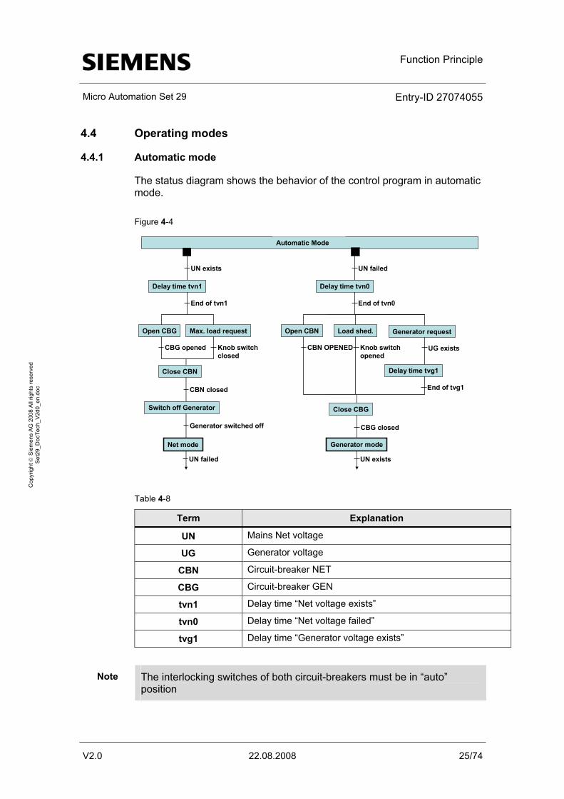
4.4.1 Automatic mode
The status diagram shows the behavior of the control program in automatic mode. Figure 4-4
Delay time tvn1
Close CBN
UN exists
End of tvn1
CBN closed
Net mode
Open CBG Max. load request
CBG opened Knob switchclosed
Switch off Generator
Generator switched off
Delay time tvn0
Close CBG
UN failed
End of tvn0
CBG closed
Open CBN Load shed.
CBN OPENED Knob switchopened
Generator request
UG exists
Delay time tvg1
End of tvg1
Generator mode
Automatic Mode
UN failed UN exists
Table 4-8
Term Explanation
UN Mains Net voltage
UG Generator voltage
CBN Circuit-breaker NET
CBG Circuit-breaker GEN
tvn1 Delay time “Net voltage exists”
tvn0 Delay time “Net voltage failed”
tvg1 Delay time “Generator voltage exists”
Note The interlocking switches of both circuit-breakers must be in “auto” position
Function Principle
Micro Automation Set 29 Entry-ID 27074055
V2.0 22.08.2008 26/74
Cop
yrig
ht ©
Sie
men
s A
G 2
008
All
right
s re
serv
ed
Set
29_D
ocTe
ch_V
2d0_
en.d
oc
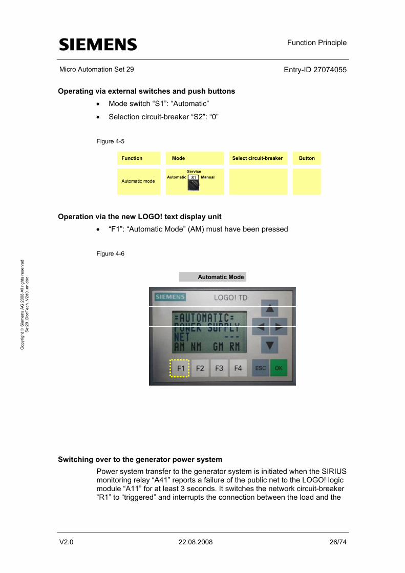
Operating via external switches and push buttons • Mode switch “S1”: “Automatic”
• Selection circuit-breaker “S2”: “0”
Figure 4-5
Automatic ManualService
Automatic mode
Function Mode Select circuit-breaker Button
S1
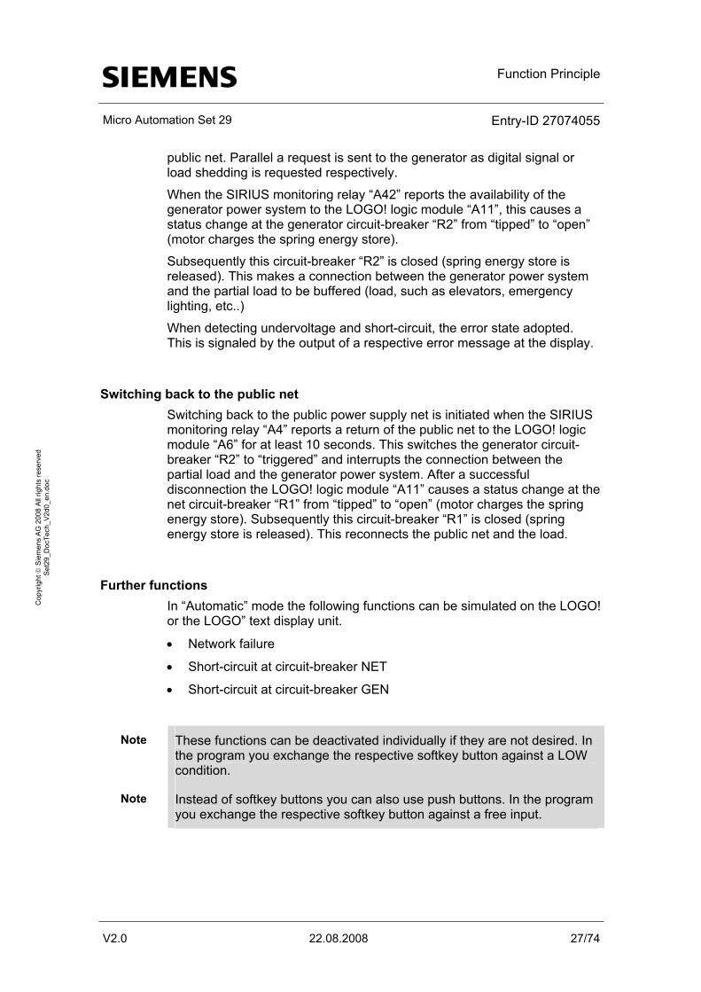
Operation via the new LOGO! text display unit • “F1”: “Automatic Mode” (AM) must have been pressed
Figure 4-6
Automatic Mode
Switching over to the generator power system Power system transfer to the generator system is initiated when the SIRIUS monitoring relay “A41” reports a failure of the public net to the LOGO! logic module “A11” for at least 3 seconds. It switches the network circuit-breaker “R1” to “triggered” and interrupts the connection between the load and the
Function Principle
Micro Automation Set 29 Entry-ID 27074055
V2.0 22.08.2008 27/74
Cop
yrig
ht ©
Sie
men
s A
G 2
008
All
right
s re
serv
ed
Set
29_D
ocTe
ch_V
2d0_
en.d
oc
public net. Parallel a request is sent to the generator as digital signal or load shedding is requested respectively.
When the SIRIUS monitoring relay “A42” reports the availability of the generator power system to the LOGO! logic module “A11”, this causes a status change at the generator circuit-breaker “R2” from “tipped” to “open” (motor charges the spring energy store).
Subsequently this circuit-breaker “R2” is closed (spring energy store is released). This makes a connection between the generator power system and the partial load to be buffered (load, such as elevators, emergency lighting, etc..)
When detecting undervoltage and short-circuit, the error state adopted. This is signaled by the output of a respective error message at the display.
Switching back to the public net Switching back to the public power supply net is initiated when the SIRIUS monitoring relay “A4” reports a return of the public net to the LOGO! logic module “A6” for at least 10 seconds. This switches the generator circuit-breaker “R2” to “triggered” and interrupts the connection between the partial load and the generator power system. After a successful disconnection the LOGO! logic module “A11” causes a status change at the net circuit-breaker “R1” from “tipped” to “open” (motor charges the spring energy store). Subsequently this circuit-breaker “R1” is closed (spring energy store is released). This reconnects the public net and the load.
Further functions In “Automatic” mode the following functions can be simulated on the LOGO! or the LOGO” text display unit.
• Network failure
• Short-circuit at circuit-breaker NET
• Short-circuit at circuit-breaker GEN
Note These functions can be deactivated individually if they are not desired. In the program you exchange the respective softkey button against a LOW condition.
Note Instead of softkey buttons you can also use push buttons. In the program you exchange the respective softkey button against a free input.
Function Principle
Micro Automation Set 29 Entry-ID 27074055
V2.0 22.08.2008 28/74
Cop
yrig
ht ©
Sie
men
s A
G 2
008
All
right
s re
serv
ed
Set
29_D
ocTe
ch_V
2d0_
en.d
oc
Figure 4-7
Automatic Mode
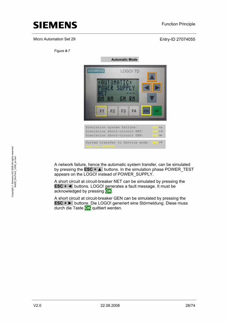
Simulation system failure: ESC+▲Simulation short-circuit NET: ESC+◄Simulation short-circuit GEN: ESC+►
System transfer to Service mode: ESC+▼Only for LOGO!TD
A network failure, hence the automatic system transfer, can be simulated by pressing the ESC + ▲ buttons. In the simulation phase POWER_TEST appears on the LOGO! instead of POWER_SUPPLY.
A short circuit at circuit-breaker NET can be simulated by pressing the ESC + ◄ buttons. LOGO! generates a fault message. It must be acknowledged by pressing OK.
A short circuit at circuit-breaker GEN can be simulated by pressing the ESC + ► buttons. Die LOGO! generiert eine Störmeldung. Diese muss durch die Taste OK quittiert werden.

Function Principle
Micro Automation Set 29 Entry-ID 27074055
V2.0 22.08.2008 29/74
Cop
yrig
ht ©
Sie
men
s A
G 2
008
All
right
s re
serv
ed
Set
29_D
ocTe
ch_V
2d0_
en.d
oc
4.4.2 Manual operation
Circuit-breaker For maintenance purposes both circuit-breakers can be opened and closed manually. The following conditions must be fulfilled for this.
Note The interlocking switches of both circuit-breakers must be in “auto” position
Operating via external switches and push buttons • Mode switch “S1”: “Manual”
• Selection circuit-breaker “S2”: “Public net” or “Generator”
Figure 4-8
Function Mode Select circuit-breaker Button
Manual:No selection
Automatic ManualService
S1 Public net Generator0
S2
Manual:“Switch on“public net
Manual:“Switch off“public net
Manual:“Switch on“generator net
Manual:“Switch off“generator net
Automatic ManualService
S1
Automatic ManualService
S1
Automatic ManualService
S1
Automatic ManualService
S1 Public net Generator0
S2
Public net Generator0
S2
Generator0
S2
Public net Generator0
S2 S3
S4
S3
S4
Public net
Opening the selected circuit-breaker and charging the spring energy store occurs after pressing the red push button “S4”.
Function Principle
Micro Automation Set 29 Entry-ID 27074055
V2.0 22.08.2008 30/74
Cop
yrig
ht ©
Sie
men
s A
G 2
008
All
right
s re
serv
ed
Set
29_D
ocTe
ch_V
2d0_
en.d
oc
Closing the circuit-breaker occurs after pressing the green push button “S3”, if the spring of the motor was previously charged. If the spring was not previously charged, the circuit-breaker remains in “triggered” mode, i.e. no connection is made between load and voltage source.
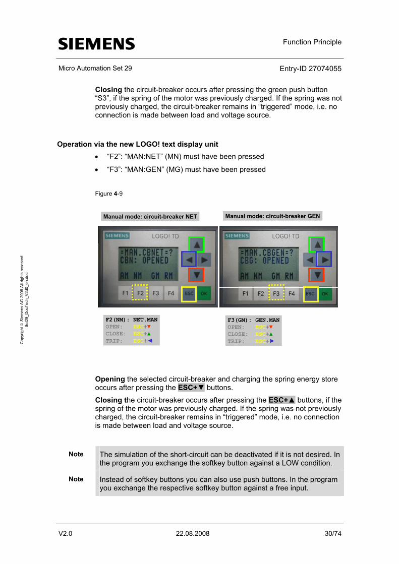
Operation via the new LOGO! text display unit • “F2”: “MAN:NET” (MN) must have been pressed
• “F3”: “MAN:GEN” (MG) must have been pressed
Figure 4-9
Manual mode: circuit-breaker NET Manual mode: circuit-breaker GEN
F2(NM): NET.MANOPEN: ESC+▼CLOSE: ESC+▲TRIP: ESC+◄
F3(GM): GEN.MANOPEN: ESC+▼CLOSE: ESC+▲TRIP: ESC+►
Opening the selected circuit-breaker and charging the spring energy store occurs after pressing the ESC+▼ buttons.
Closing the circuit-breaker occurs after pressing the ESC+▲ buttons, if the spring of the motor was previously charged. If the spring was not previously charged, the circuit-breaker remains in “triggered” mode, i.e. no connection is made between load and voltage source.
Note The simulation of the short-circuit can be deactivated if it is not desired. In the program you exchange the softkey button against a LOW condition.
Note Instead of softkey buttons you can also use push buttons. In the program you exchange the respective softkey button against a free input.
Function Principle
Micro Automation Set 29 Entry-ID 27074055
V2.0 22.08.2008 31/74
Cop
yrig
ht ©
Sie
men
s A
G 2
008
All
right
s re
serv
ed
Set
29_D
ocTe
ch_V
2d0_
en.d
oc
A short circuit at the circuit-breaker can be simulated by pressing the ESC +◄► buttons. LOGO! generates a fault. This must be acknowledged by pressing OK.
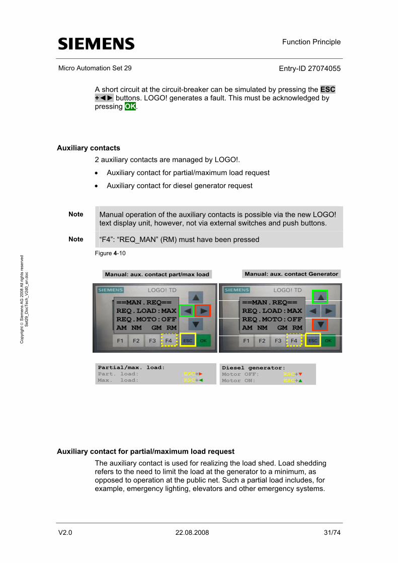
Auxiliary contacts 2 auxiliary contacts are managed by LOGO!.
• Auxiliary contact for partial/maximum load request
• Auxiliary contact for diesel generator request
Note Manual operation of the auxiliary contacts is possible via the new LOGO! text display unit, however, not via external switches and push buttons.
Note “F4”: “REQ_MAN” (RM) must have been pressed
Figure 4-10
Manual: aux. contact part/max load Manual: aux. contact Generator
Partial/max. load:Part. load: ESC+►Max. load: ESC+◄
Diesel generator:Motor OFF: ESC+▼Motor ON: ESC+▲
==MAN.REQ== REQ.LOAD:MAXREQ.MOTO:OFFAM NM GM RM
==MAN.REQ== REQ.LOAD:MAXREQ.MOTO:OFFAM NM GM RM
Auxiliary contact for partial/maximum load request The auxiliary contact is used for realizing the load shed. Load shedding refers to the need to limit the load at the generator to a minimum, as opposed to operation at the public net. Such a partial load includes, for example, emergency lighting, elevators and other emergency systems.
Function Principle
Micro Automation Set 29 Entry-ID 27074055
V2.0 22.08.2008 32/74
Cop
yrig
ht ©
Sie
men
s A
G 2
008
All
right
s re
serv
ed
Set
29_D
ocTe
ch_V
2d0_
en.d
oc
• Maximum load request is performed manually by pressing the ESC+◄ buttons. Q8:TRUE
• Partial load request is performed manually by pressing the ESC+◄ buttons. Q8:FALSE
The feedback of the request at the LOGO! occurs at input I5.
Note If no load shedding is planned, the feedback of the load shedding must be realized via a bridge.
Bridge: Output Q8(request) – Input I5(feedback)
Auxiliary contact for generator request The generator is used, in case of a power cut, to provide power to emergency lighting and other devices important for maintaining the infrastructure.
• The generator is requested manually by pressing the ESC+▲ buttons. Q5:TRUE
• The generator is cancelled manually by pressing the ESC+▼ buttons. Q5:FALSE
Function Principle
Micro Automation Set 29 Entry-ID 27074055
V2.0 22.08.2008 33/74
Cop
yrig
ht ©
Sie
men
s A
G 2
008
All
right
s re
serv
ed
Set
29_D
ocTe
ch_V
2d0_
en.d
oc
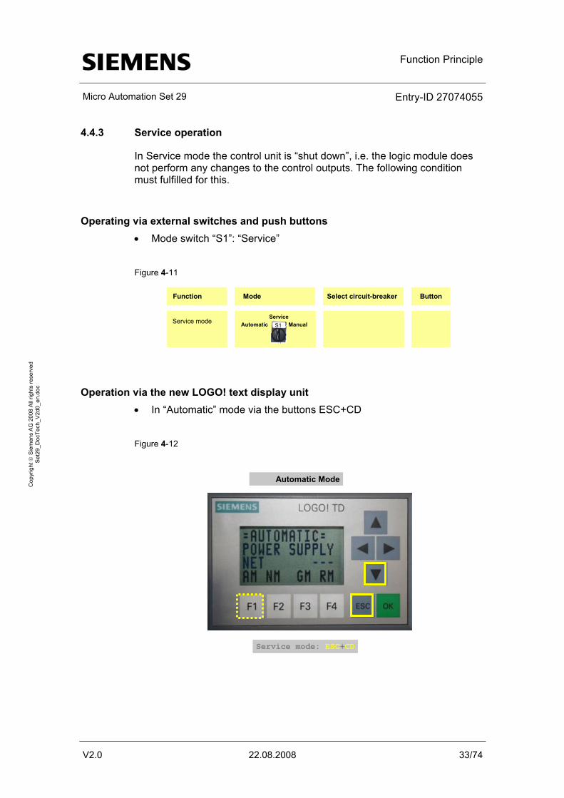
4.4.3 Service operation
In Service mode the control unit is “shut down”, i.e. the logic module does not perform any changes to the control outputs. The following condition must fulfilled for this.
Operating via external switches and push buttons • Mode switch “S1”: “Service”
Figure 4-11
Function Mode Select circuit-breaker Button
Service mode Automatic ManualService
S1
Operation via the new LOGO! text display unit • In “Automatic” mode via the buttons ESC+CD
Figure 4-12
Automatic Mode
Service mode: ESC+CD

Function Principle
Micro Automation Set 29 Entry-ID 27074055
V2.0 22.08.2008 34/74
Cop
yrig
ht ©
Sie
men
s A
G 2
008
All
right
s re
serv
ed
Set
29_D
ocTe
ch_V
2d0_
en.d
oc
4.4.4 Power management
In “Service” mode the “Power management” function can be controlled.
Note Power management can be deactivated if it is not required. In the program you exchange the softkey button against a LOW condition.
Figure 4-13
Service Mode
Power management ON (MIN): ESC+►Power management OFF(MAX): ESC+◄
Power management: ON Pressing the ESC+► buttons (LOGO! as well as LOGO!TD) activates the power management (“MIN" displayed). Auxiliary contact for partial/maximum load request remains open Q8:FALSE
Power management: OFF Pressing the ESC+◄ buttons (LOGO! as well as LOGO!TD) deactivates the power management (“MAX" displayed).
Function Principle
Micro Automation Set 29 Entry-ID 27074055
V2.0 22.08.2008 35/74
Cop
yrig
ht ©
Sie
men
s A
G 2
008
All
right
s re
serv
ed
Set
29_D
ocTe
ch_V
2d0_
en.d
oc
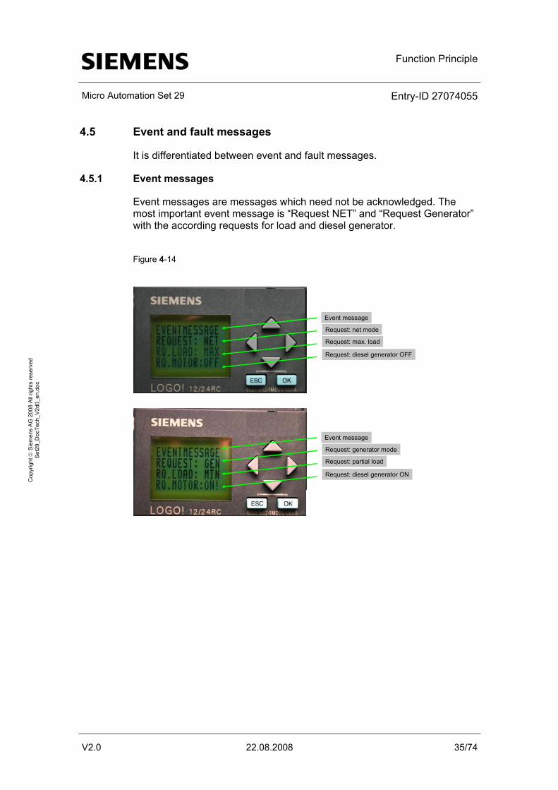
4.5 Event and fault messages
It is differentiated between event and fault messages.
4.5.1 Event messages
Event messages are messages which need not be acknowledged. The most important event message is “Request NET” and “Request Generator” with the according requests for load and diesel generator.
Figure 4-14
Event message
Request: net mode
Request: max. load
Request: diesel generator OFF
Event message
Request: generator mode
Request: partial load
Request: diesel generator ON
Function Principle
Micro Automation Set 29 Entry-ID 27074055
V2.0 22.08.2008 36/74
Cop
yrig
ht ©
Sie
men
s A
G 2
008
All
right
s re
serv
ed
Set
29_D
ocTe
ch_V
2d0_
en.d
oc
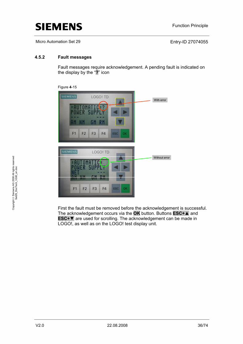
4.5.2 Fault messages
Fault messages require acknowledgement. A pending fault is indicated on the display by the “?” icon
Figure 4-15
Without error
With error
First the fault must be removed before the acknowledgement is successful. The acknowledgement occurs via the OK button. Buttons ESC+▲ and ESC+▼ are used for scrolling. The acknowledgement can be made in LOGO!, as well as on the LOGO! test display unit.
Function Principle
Micro Automation Set 29 Entry-ID 27074055
V2.0 22.08.2008 37/74
Cop
yrig
ht ©
Sie
men
s A
G 2
008
All
right
s re
serv
ed
Set
29_D
ocTe
ch_V
2d0_
en.d
oc
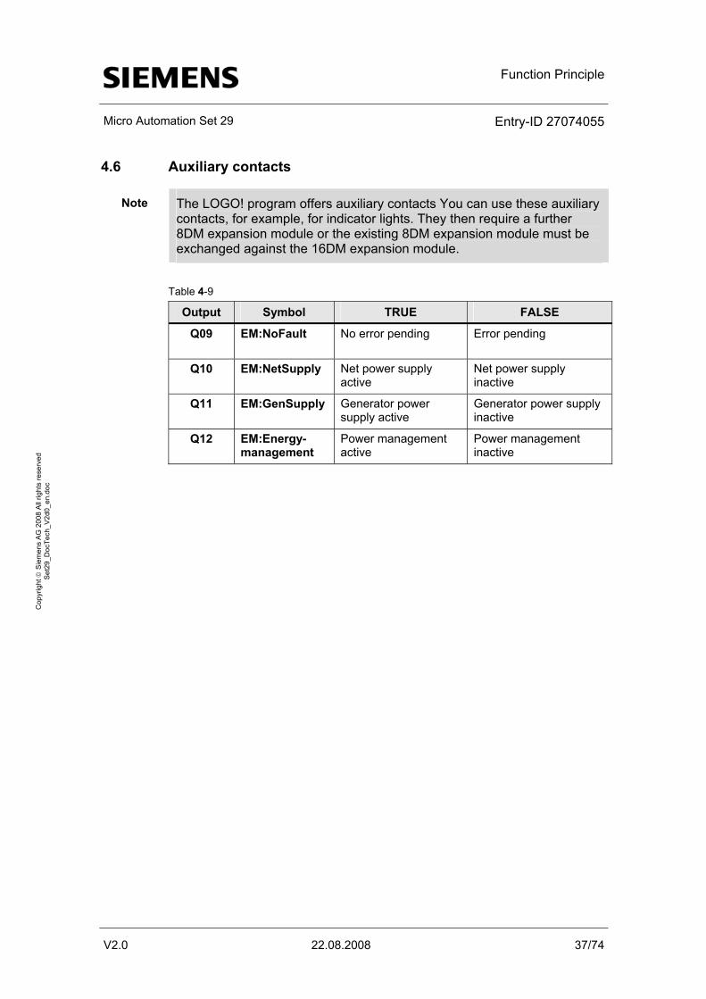
4.6 Auxiliary contacts
Note The LOGO! program offers auxiliary contacts You can use these auxiliary contacts, for example, for indicator lights. They then require a further 8DM expansion module or the existing 8DM expansion module must be exchanged against the 16DM expansion module.
Table 4-9
Output Symbol TRUE FALSE
Q09
EM:NoFault No error pending Error pending
Q10
EM:NetSupply Net power supply active
Net power supply inactive
Q11
EM:GenSupply Generator power supply active
Generator power supply inactive
Q12
EM:Energy-management
Power management active
Power management inactive
Function Principle
Micro Automation Set 29 Entry-ID 27074055
V2.0 22.08.2008 38/74
Cop
yrig
ht ©
Sie
men
s A
G 2
008
All
right
s re
serv
ed
Set
29_D
ocTe
ch_V
2d0_
en.d
oc
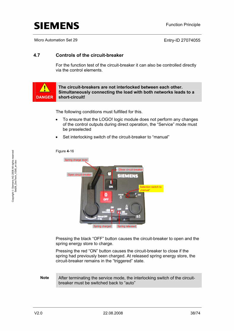
4.7 Controls of the circuit-breaker
For the function test of the circuit-breaker it can also be controlled directly via the control elements.
!
DANGER
The circuit-breakers are not interlocked between each other. Simultaneously connecting the load with both networks leads to a short-circuit!
The following conditions must fulfilled for this.
• To ensure that the LOGO! logic module does not perform any changes of the control outputs during direct operation, the “Service” mode must be preselected
• Set interlocking switch of the circuit-breaker to “manual”
Figure 4-16
Close circuit-breaker
Open circuit-breaker
Spring charge lever
Selection switch to„manual“
Spring charged Spring released
Pressing the black “OFF” button causes the circuit-breaker to open and the spring energy store to charge.
Pressing the red “ON” button causes the circuit-breaker to close if the spring had previously been charged. At released spring energy store, the circuit-breaker remains in the “triggered” state.
Note After terminating the service mode, the interlocking switch of the circuit-breaker must be switched back to “auto”
Function Principle
Micro Automation Set 29 Entry-ID 27074055
V2.0 22.08.2008 39/74
Cop
yrig
ht ©
Sie
men
s A
G 2
008
All
right
s re
serv
ed
Set
29_D
ocTe
ch_V
2d0_
en.d
oc
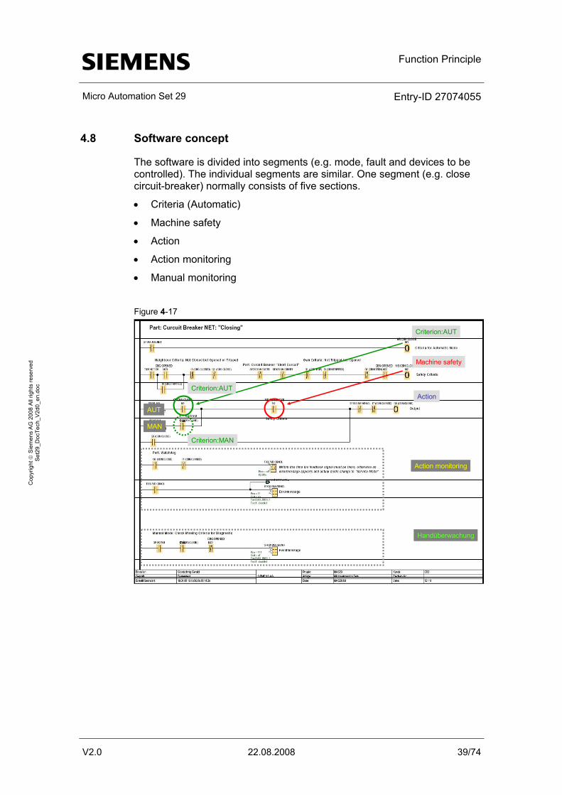
4.8 Software concept
The software is divided into segments (e.g. mode, fault and devices to be controlled). The individual segments are similar. One segment (e.g. close circuit-breaker) normally consists of five sections.
• Criteria (Automatic)
• Machine safety
• Action
• Action monitoring
• Manual monitoring
Figure 4-17
Criterion:AUT
Machine safety
Action
Action monitoring
Handüberwachung
MAN
AUT
Criterion:MAN
Criterion:AUT
Function Principle
Micro Automation Set 29 Entry-ID 27074055
V2.0 22.08.2008 40/74
Cop
yrig
ht ©
Sie
men
s A
G 2
008
All
right
s re
serv
ed
Set
29_D
ocTe
ch_V
2d0_
en.d
oc
4.8.1 Criteria (Automatic)
Here all conditions are stored which apply for the automatic operation (e.g network failure).
4.8.2 Machine safety
Here all conditions are stored which apply for safety (e.g no fault, the other circuit-breaker is opened). The machine safety is independent of the operation.
4.8.3 Action
An action is performed if apart from the machine safety for
• “AUTOMATIC” mode the criteria for automatic
• “MANUAL” mode the criteria for manual
is fulfilled
4.8.4 Action monitoring
A started action is monitored. If within the monitoring time the position to be moved to is not reached, the LOGO! generates a fault. This fault cancels the started action. The cause of the fault is shown at the display and must be removed before being able to acknowledge with the “OK” button.
4.8.5 Manual monitoring
Indicates which conditions are missing in manual mode.
Configuration of the Startup Software
Micro Automation Set 29 Entry-ID 27074055
V2.0 22.08.2008 41/74
Cop
yrig
ht ©
Sie
men
s A
G 2
008
All
right
s re
serv
ed
Set
29_D
ocTe
ch_V
2d0_
en.d
oc
5 Configuration of the Startup Software
5.1 Preliminary remarks
For the startup we offer you software examples with test code and test parameters as a download. The software examples support you during the first steps and tests with your Micro Automation Sets. They enable quick testing of hardware and software interfaces between the products described in the Micro Automation Sets.
The software examples are always assigned to the components used in the set and show their basic interaction. However, they are not real applications in the sense of technological problem solving with definable properties.
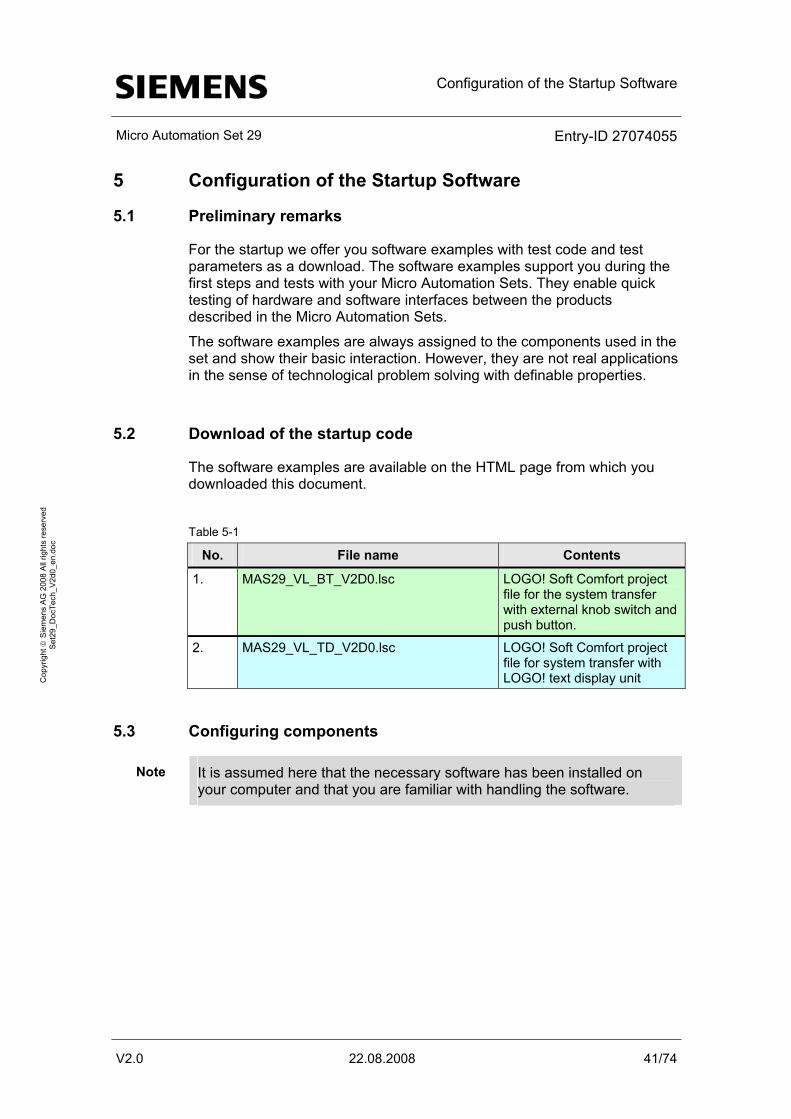
5.2 Download of the startup code
The software examples are available on the HTML page from which you downloaded this document.
Table 5-1
No. File name Contents
1. MAS29_VL_BT_V2D0.lsc LOGO! Soft Comfort project file for the system transfer with external knob switch and push button.
2. MAS29_VL_TD_V2D0.lsc LOGO! Soft Comfort project file for system transfer with LOGO! text display unit
5.3 Configuring components
Note It is assumed here that the necessary software has been installed on your computer and that you are familiar with handling the software.
Configuration of the Startup Software
Micro Automation Set 29 Entry-ID 27074055
V2.0 22.08.2008 42/74
Cop
yrig
ht ©
Sie
men
s A
G 2
008
All
right
s re
serv
ed
Set
29_D
ocTe
ch_V
2d0_
en.d
oc
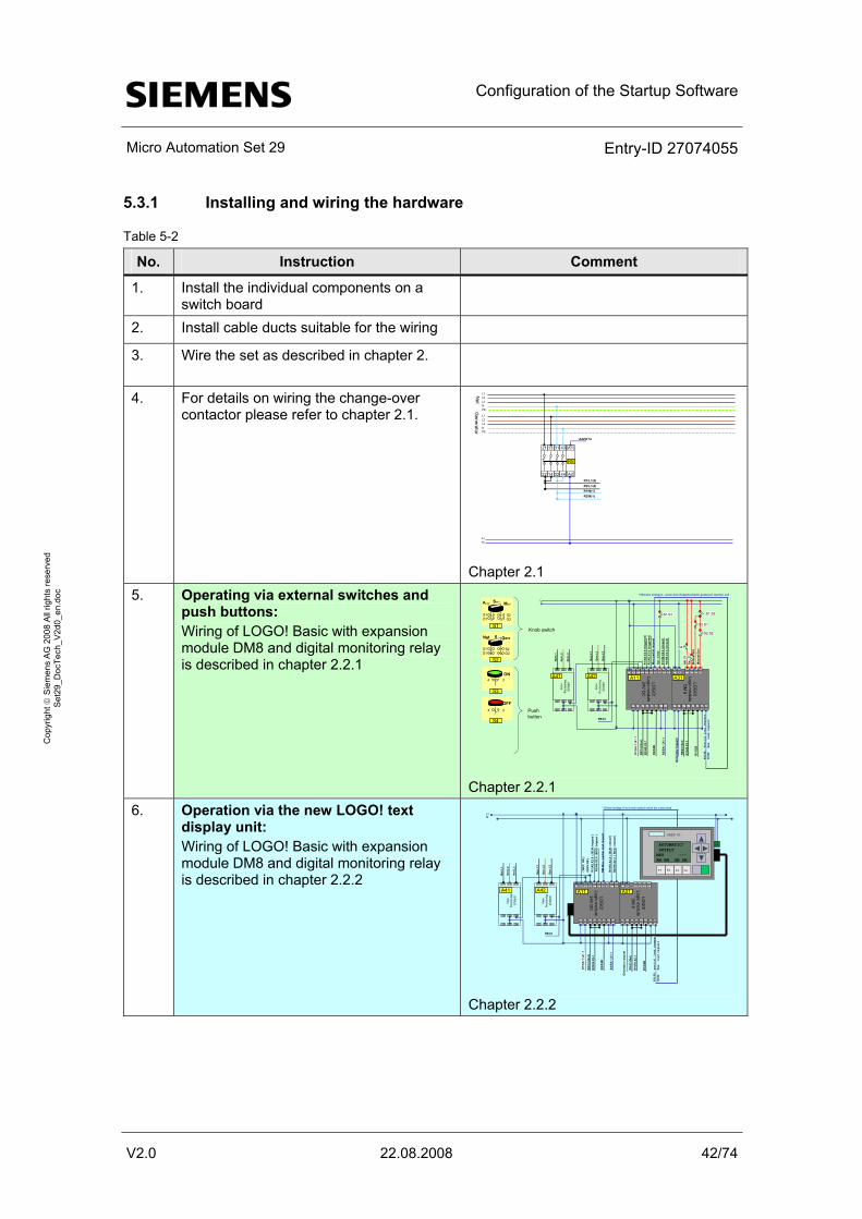
5.3.1 Installing and wiring the hardware
Table 5-2
No. Instruction Comment
1. Install the individual components on a switch board
2. Install cable ducts suitable for the wiring
3. Wire the set as described in chapter 2.
4. For details on wiring the change-over contactor please refer to chapter 2.1.
L+M
21 13 31 43
22 14 32 44
R8
A1
A2R1\L1(4)R2\L1(4)R1\N(1)R2\N(1)
A42\K14
L1L2L3NPE
L1L2L3NPE
Net
Generator
Chapter 2.1
5. Operating via external switches and push buttons: Wiring of LOGO! Basic with expansion module DM8 and digital monitoring relay is described in chapter 2.2.1
R8\
14 (G
en)
LOG
O!
Logicm
odule24V D
C
L1 I1N I3 I6I2 I5 I7Î4 I8
Q11 Q31Q12 Q22Q21 Q32Q41Q42
LOG
O!
Logicm
oduleD
M 8
L1 I1N I3I2 Î4
Q11 Q31Q12 Q22Q21 Q32Q41Q42
L+M
L1 L2 L3
22 2421
12 1411
SIRIU
SM
onitoringrelay
R2\
S2B
R1\
AS.X
2.6
(trig
gere
d)
R1\
HS.X
2.4
(clo
sed)
A11 A31A41
Net:L
1
Net:L
2
Net:L
3
R8\
22 (N
et)
R1\
S2B
R2\
HS.X
2.4
(clo
sed)
L1 L2 L3
22 2421
12 1411
SIRIU
SM
onitoringrelay
A42
Gen
:L1
Gen
:L2
Gen
:L3
R8\A1
Max
./par
tial r
eque
st
Auto ManServ
S1Ö1
S2Ö2
S1
Net Gen0
S1Ö1
S2
S2Ö2
S2.S2
R2\
HS.
X2.1
4
S3
3
S4
Knob switch
Push button
R1\
SA:
1.\X
1.1
R1\
HS.
X2.1
Gen
erat
or re
ques
t
R2\
SA:
1.X1
.1
R2\
AS.X
2.6
(trig
gere
d)
S1.S1
Aut.
mod
e
Off
S3
On
S2.S1
Man
ual N
et
Man
ual G
en
ON
OFF
S1.S2
4 3
S4
FAL
SE: Partial loa
d reques
tTRU
E: Max. load r
equest
*) Brücke einlegen,, wenn kein Koppelschalter gesteuert werden soll
Chapter 2.2.1
6. Operation via the new LOGO! text display unit: Wiring of LOGO! Basic with expansion module DM8 and digital monitoring relay is described in chapter 2.2.2
s LOGO! TD
F1 F3F2 F4
R8\
14 (G
en)
LOG
O!
Logic module
24V DC
L1 I1N I3 I6I2 I5 I7Î4 I8
Q11 Q31Q12 Q22Q21 Q32Q41Q42
LOG
O!
Logic module
DM
8
L1 I1N I3I2 Î4
Q11 Q31Q12 Q22Q21 Q32Q41Q42
L+M
L1 L2 L3
22 2421
12 1411
SIR
IUS
Monitoringrelay
R2\
S2B
R1\
AS.
X2.6
( B
CN:
trip
ped
)
R1\
HS.
X2.4
( B
CN:
clo
sed
)
A11 A31A41
Net
:L1
Net
:L2
Net
:L3
R8\
22 (N
et)
R1\
S2B
R2\
HS.
X2.4
( B
CG
: clo
sed
)
L1 L2 L3
22 2421
12 1411
SIR
IUS
Monitoringrelay
A42
Gen
:L1
Gen
:L2
Gen
:L3
R8\A1
R2\
HS.
X2.1
R1\
SA:
1.\X
1.1
R1\
HS.
X2.1
Gen
erat
or r
eque
st
R2\
SA:
1.X
1.1
R2\
AS.
X2.6
(B
CG
: tri
pped
)
( NET
: OK
)(G
EN:O
K )
AUTOMATIC! SUPPLYNET ---AM NM GM SM
FALS
E: p
artia
l load
req
uest
TRUE
: M
ax. l
oad re
ques
t
RM
-Max
. /pa
rtia
l loa
dre
ques
t
*) Enter bridge if no knob switch shall be controlled
Chapter 2.2.2
Configuration of the Startup Software
Micro Automation Set 29 Entry-ID 27074055
V2.0 22.08.2008 43/74
Cop
yrig
ht ©
Sie
men
s A
G 2
008
All
right
s re
serv
ed
Set
29_D
ocTe
ch_V
2d0_
en.d
oc
No. Instruction Comment
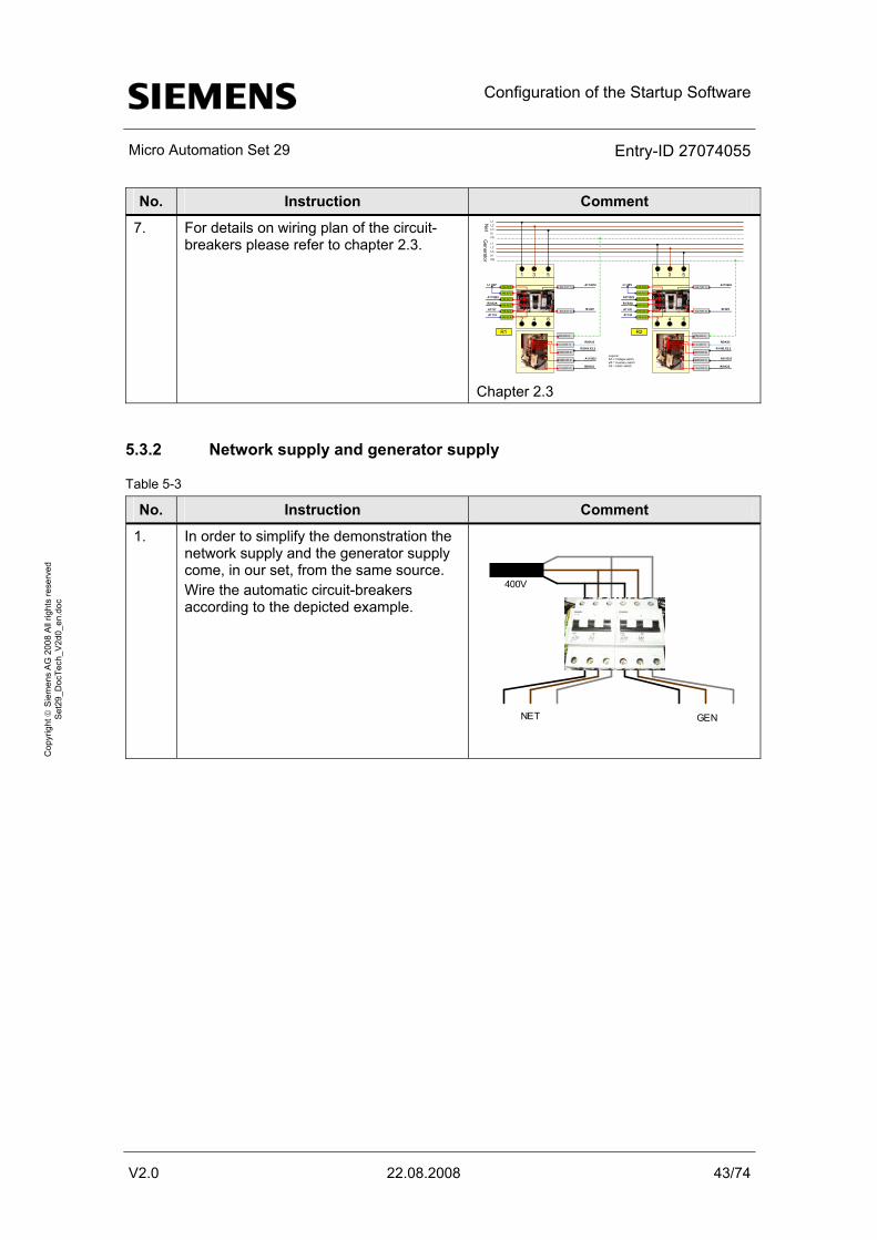
7. For details on wiring plan of the circuit-breakers please refer to chapter 2.3.
R2\HS.X2.2
A11\Q32Legend:SA = Voltage switchHS = Auxiliary switchAS = Alarm switchR8\K22
L1L2L3NPE
L1L2L3NPE
Net
Generator
1
2
3
4
5
6
HS.X2.1
HS.X2.2
HS.X2.3
HS.X2.4
AS.X2.5
AS.X2.6
SA:1(X1.1)
SA:2(X1.2)
R1PE(X20.5)
S2A(X20.2)
L2-(X20.1)
L2+(X20.4)
S2B(X20.3)
M 24V
R8\K32
A11\Q12
A11\Q22
R2\S2A
A11\I7
L+ 24V
A11\I3
R1\HS.X2.2
A31\Q32
R8\K22
1
2
3
4
5
6
HS.X2.1
HS.X2.2
HS.X2.3
HS.X2.4
AS.X2.5
AS.X2.6
SA:1(X1.1)
SA:2(X1.2)
R2PE(X20.5)
S2A(X20.2)
L2-(X20.1)
L2+(X20.4)
S2B(X20.3)
M 24V
R8\K32
A11\Q42
A31\Q22
R1\S2A
A11\I8
L+ 24V
A11\I4
Chapter 2.3
5.3.2 Network supply and generator supply
Table 5-3
No. Instruction Comment
1. In order to simplify the demonstration the network supply and the generator supply come, in our set, from the same source. Wire the automatic circuit-breakers according to the depicted example.
NET GEN
400V
Configuration of the Startup Software
Micro Automation Set 29 Entry-ID 27074055
V2.0 22.08.2008 44/74
Cop
yrig
ht ©
Sie
men
s A
G 2
008
All
right
s re
serv
ed
Set
29_D
ocTe
ch_V
2d0_
en.d
oc
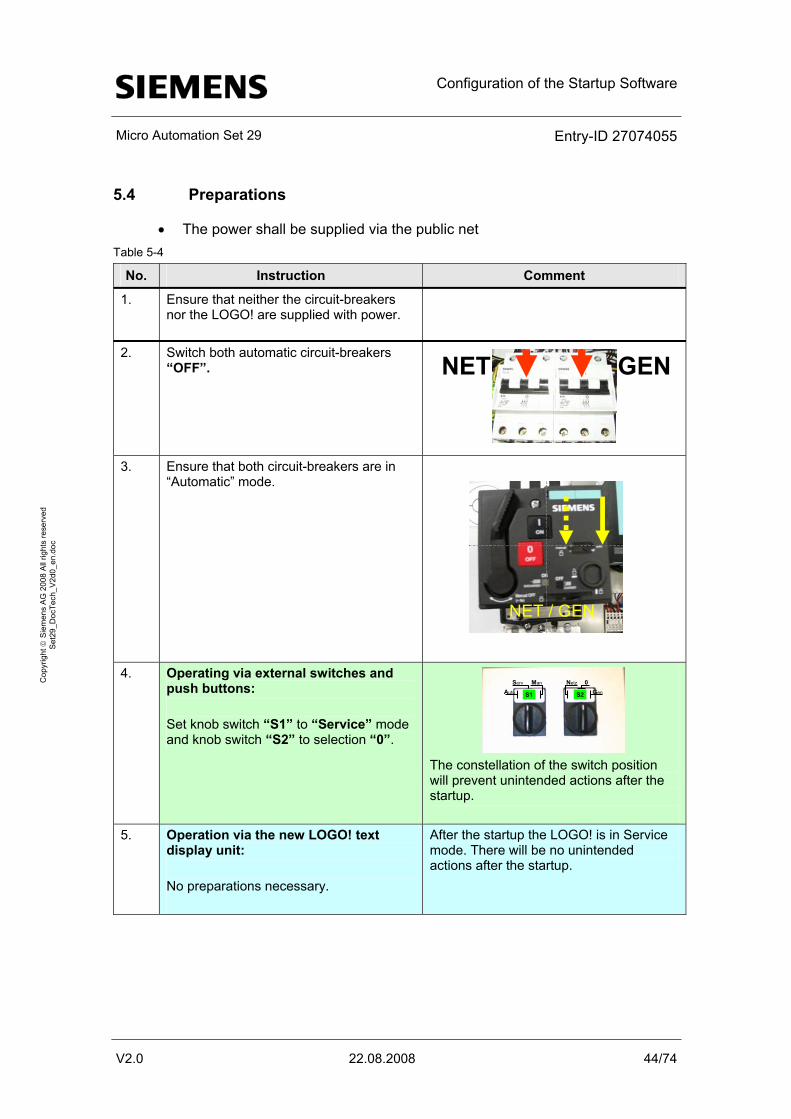
5.4 Preparations
• The power shall be supplied via the public net Table 5-4
No. Instruction Comment
1. Ensure that neither the circuit-breakers nor the LOGO! are supplied with power.
2. Switch both automatic circuit-breakers “OFF”. NET GEN
3. Ensure that both circuit-breakers are in
“Automatic” mode.
NET / GEN
4. Operating via external switches and push buttons: Set knob switch “S1” to “Service” mode and knob switch “S2” to selection “0”.
S1 S2Auto
Serv Man Netz 0Gen
The constellation of the switch position will prevent unintended actions after the startup.
5. Operation via the new LOGO! text display unit: No preparations necessary.
After the startup the LOGO! is in Service mode. There will be no unintended actions after the startup.
Configuration of the Startup Software
Micro Automation Set 29 Entry-ID 27074055
V2.0 22.08.2008 45/74
Cop
yrig
ht ©
Sie
men
s A
G 2
008
All
right
s re
serv
ed
Set
29_D
ocTe
ch_V
2d0_
en.d
oc
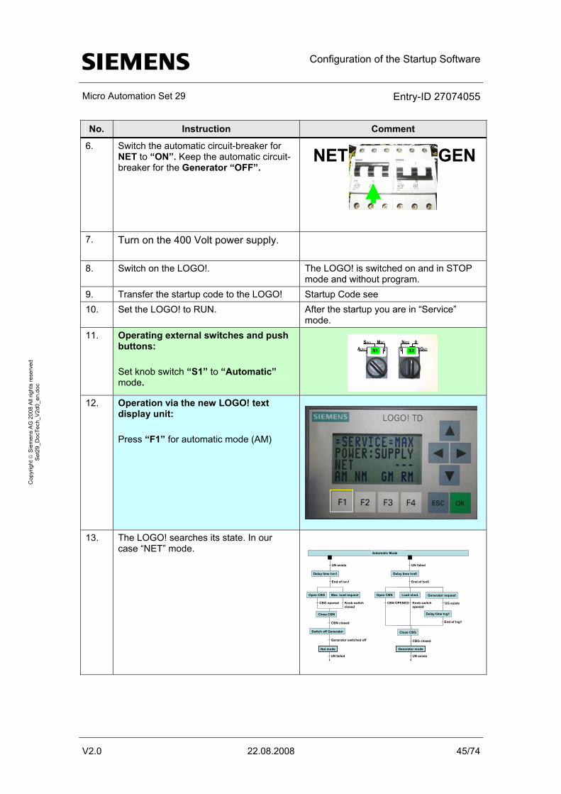
No. Instruction Comment
6. Switch the automatic circuit-breaker for NET to “ON”. Keep the automatic circuit-breaker for the Generator “OFF”.
NET GEN
7. Turn on the 400 Volt power supply.
8. Switch on the LOGO!. The LOGO! is switched on and in STOP mode and without program.
9. Transfer the startup code to the LOGO! Startup Code see 10. Set the LOGO! to RUN. After the startup you are in “Service”
mode. 11. Operating external switches and push
buttons: Set knob switch “S1” to “Automatic” mode.
S1 S2Auto
Serv Man Netz 0Gen
12. Operation via the new LOGO! text display unit: Press “F1” for automatic mode (AM)
13. The LOGO! searches its state. In our
case “NET” mode.
Delay time tvn1
Close CBN
UN exists
End of tvn1
CBN closed
Net mode
Open CBG Max. load request
CBG opened Knob switchclosed
Switch off Generator
Generator switched off
Delay time tvn0
Close CBG
UN failed
End of tvn0
CBG closed
Open CBN Load shed.
CBN OPENED Knob switchopened
Generator request
UG exists
Delay time tvg1
End of tvg1
Generator mode
Automatic Mode
UN failed UN exists
Configuration of the Startup Software
Micro Automation Set 29 Entry-ID 27074055
V2.0 22.08.2008 46/74
Cop
yrig
ht ©
Sie
men
s A
G 2
008
All
right
s re
serv
ed
Set
29_D
ocTe
ch_V
2d0_
en.d
oc
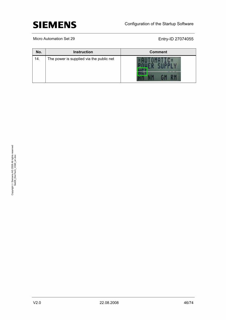
No. Instruction Comment
14. The power is supplied via the public net
Live-Demo
Micro Automation Set 29 Entry-ID 27074055
V2.0 22.08.2008 47/74
Cop
yrig
ht ©
Sie
men
s A
G 2
008
All
right
s re
serv
ed
Set
29_D
ocTe
ch_V
2d0_
en.d
oc
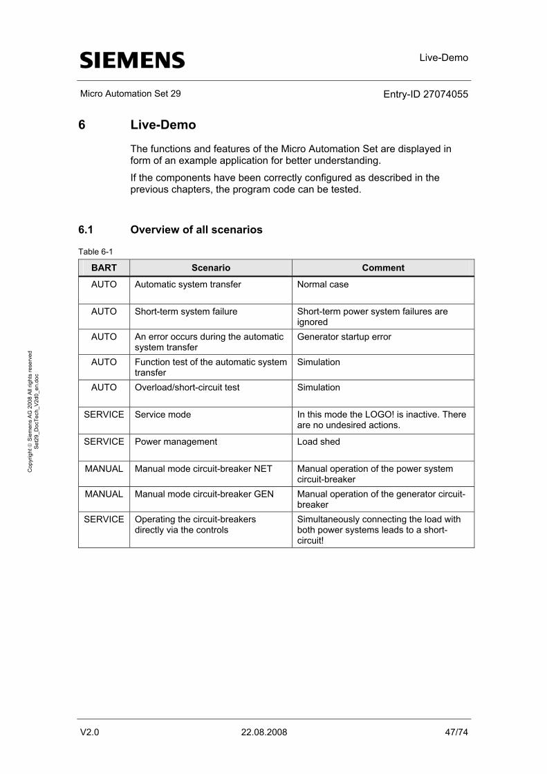
6 Live-Demo
The functions and features of the Micro Automation Set are displayed in form of an example application for better understanding.
If the components have been correctly configured as described in the previous chapters, the program code can be tested.
6.1 Overview of all scenarios
Table 6-1
BART Scenario Comment
AUTO Automatic system transfer
Normal case
AUTO Short-term system failure Short-term power system failures are ignored
AUTO An error occurs during the automatic system transfer
Generator startup error
AUTO Function test of the automatic system transfer
Simulation
AUTO Overload/short-circuit test
Simulation
SERVICE Service mode
In this mode the LOGO! is inactive. There are no undesired actions.
SERVICE Power management
Load shed
MANUAL Manual mode circuit-breaker NET Manual operation of the power system circuit-breaker
MANUAL Manual mode circuit-breaker GEN Manual operation of the generator circuit-breaker
SERVICE Operating the circuit-breakers directly via the controls
Simultaneously connecting the load with both power systems leads to a short-circuit!
Live-Demo
Micro Automation Set 29 Entry-ID 27074055
V2.0 22.08.2008 48/74
Cop
yrig
ht ©
Sie
men
s A
G 2
008
All
right
s re
serv
ed
Set
29_D
ocTe
ch_V
2d0_
en.d
oc
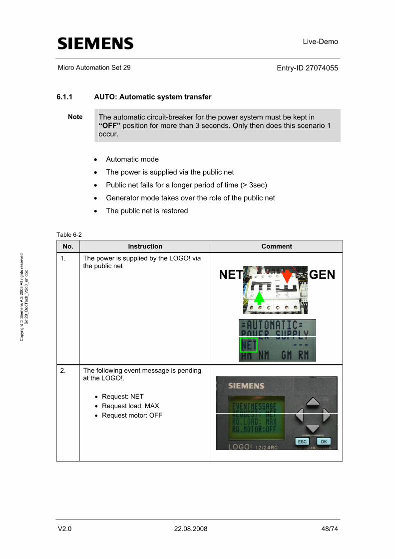
6.1.1 AUTO: Automatic system transfer
Note The automatic circuit-breaker for the power system must be kept in “OFF” position for more than 3 seconds. Only then does this scenario 1 occur.
• Automatic mode
• The power is supplied via the public net
• Public net fails for a longer period of time (> 3sec)
• Generator mode takes over the role of the public net
• The public net is restored
Table 6-2
No. Instruction Comment
1. The power is supplied by the LOGO! via the public net
NET GEN
2. The following event message is pending
at the LOGO!.
• Request: NET • Request load: MAX • Request motor: OFF
Live-Demo
Micro Automation Set 29 Entry-ID 27074055
V2.0 22.08.2008 49/74
Cop
yrig
ht ©
Sie
men
s A
G 2
008
All
right
s re
serv
ed
Set
29_D
ocTe
ch_V
2d0_
en.d
oc
No. Instruction Comment
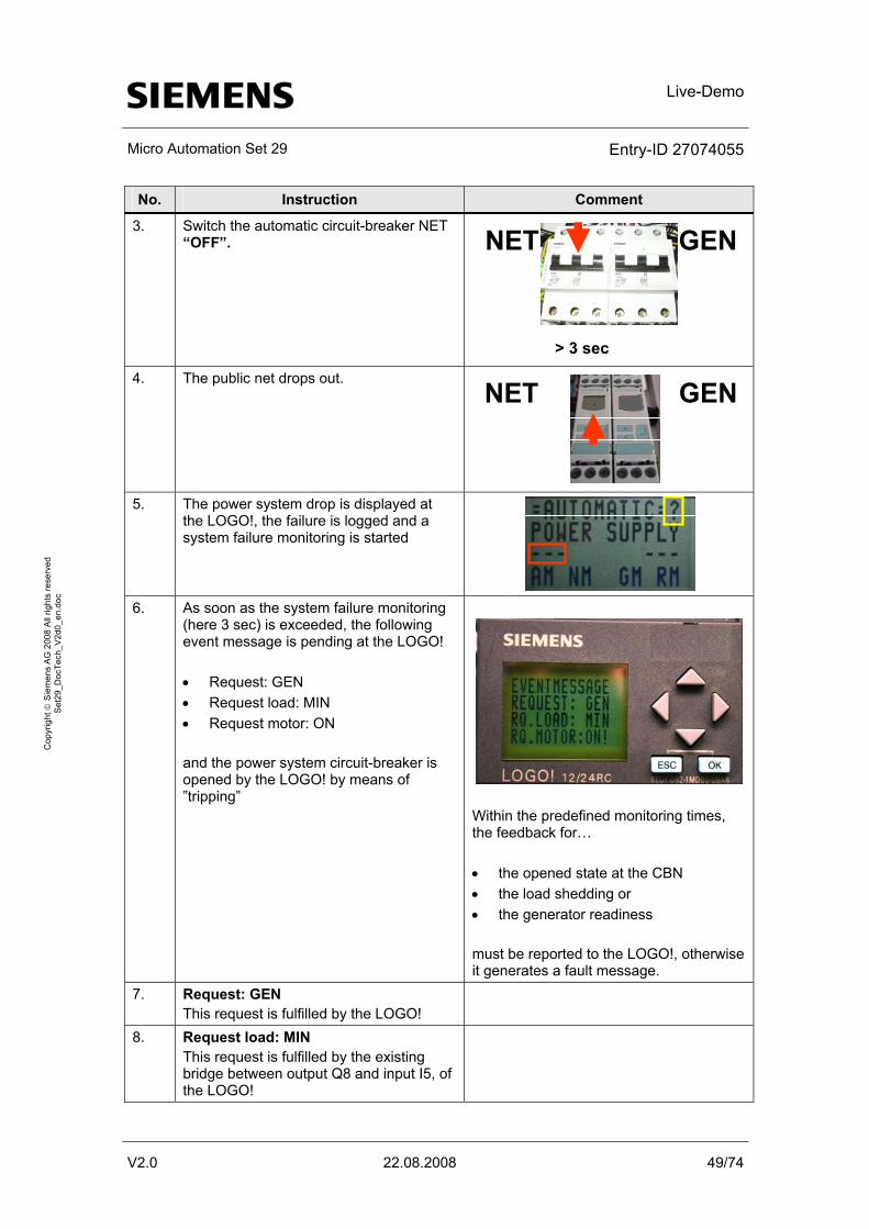
3. Switch the automatic circuit-breaker NET “OFF”. NET GEN
> 3 sec
4. The public net drops out. NET GEN
5. The power system drop is displayed at
the LOGO!, the failure is logged and a system failure monitoring is started
6. As soon as the system failure monitoring
(here 3 sec) is exceeded, the following event message is pending at the LOGO! • Request: GEN • Request load: MIN • Request motor: ON and the power system circuit-breaker is opened by the LOGO! by means of ”tripping”
Within the predefined monitoring times, the feedback for… • the opened state at the CBN • the load shedding or • the generator readiness must be reported to the LOGO!, otherwise it generates a fault message.
7. Request: GEN This request is fulfilled by the LOGO!
8. Request load: MIN This request is fulfilled by the existing bridge between output Q8 and input I5, of the LOGO!
Live-Demo
Micro Automation Set 29 Entry-ID 27074055
V2.0 22.08.2008 50/74
Cop
yrig
ht ©
Sie
men
s A
G 2
008
All
right
s re
serv
ed
Set
29_D
ocTe
ch_V
2d0_
en.d
oc
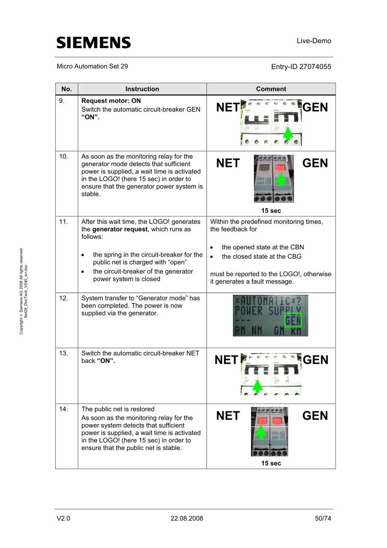
No. Instruction Comment
9. Request motor: ON Switch the automatic circuit-breaker GEN “ON”.
NET GEN
10. As soon as the monitoring relay for the
generator mode detects that sufficient power is supplied, a wait time is activated in the LOGO! (here 15 sec) in order to ensure that the generator power system is stable.
NET GEN
15 sec
11. After this wait time, the LOGO! generates the generator request, which runs as follows: • the spring in the circuit-breaker for the
public net is charged with “open” • the circuit-breaker of the generator
power system is closed
Within the predefined monitoring times, the feedback for • the opened state at the CBN • the closed state at the CBG must be reported to the LOGO!, otherwise it generates a fault message.
12. System transfer to “Generator mode” has been completed. The power is now supplied via the generator.
13. Switch the automatic circuit-breaker NET back “ON”. NET GEN
14. The public net is restored
As soon as the monitoring relay for the power system detects that sufficient power is supplied, a wait time is activated in the LOGO! (here 15 sec) in order to ensure that the public net is stable.
NET GEN
15 sec
Live-Demo
Micro Automation Set 29 Entry-ID 27074055
V2.0 22.08.2008 51/74
Cop
yrig
ht ©
Sie
men
s A
G 2
008
All
right
s re
serv
ed
Set
29_D
ocTe
ch_V
2d0_
en.d
oc
No. Instruction Comment
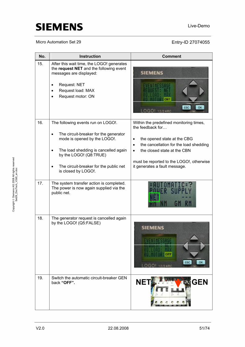
15. After this wait time, the LOGO! generates the request NET and the following event messages are displayed: • Request: NET • Request load: MAX • Request motor: ON
ON!
16. The following events run on LOGO!.
• The circuit-breaker for the generator
mode is opened by the LOGO!. • The load shedding is cancelled again
by the LOGO! (Q8:TRUE) • The circuit-breaker for the public net
is closed by LOGO!.
Within the predefined monitoring times, the feedback for… • the opened state at the CBG • the cancellation for the load shedding • the closed state at the CBN must be reported to the LOGO!, otherwise it generates a fault message.
17. The system transfer action is completed. The power is now again supplied via the public net.
?
18. The generator request is cancelled again by the LOGO! (Q5:FALSE)
OFF
19. Switch the automatic circuit-breaker GEN
back “OFF”. NET GEN

Live-Demo
Micro Automation Set 29 Entry-ID 27074055
V2.0 22.08.2008 52/74
Cop
yrig
ht ©
Sie
men
s A
G 2
008
All
right
s re
serv
ed
Set
29_D
ocTe
ch_V
2d0_
en.d
oc
No. Instruction Comment
20. However, a fault which requires acknowledgement is still pending. Noticeable by the displayed “?” icon.
?
21. The logged “ShutDown Net” fault can be
acknowledged by you on the LOGO!, alternatively at the text display unit, using the OK button. To do this go to the individual fault and acknowledge.
ERRORMESSAGE
AM NM GM RM2008-08-08 ShutDown NET
22. No fault is pending if the “?” icon is no longer displayed.
Live-Demo
Micro Automation Set 29 Entry-ID 27074055
V2.0 22.08.2008 53/74
Cop
yrig
ht ©
Sie
men
s A
G 2
008
All
right
s re
serv
ed
Set
29_D
ocTe
ch_V
2d0_
en.d
oc
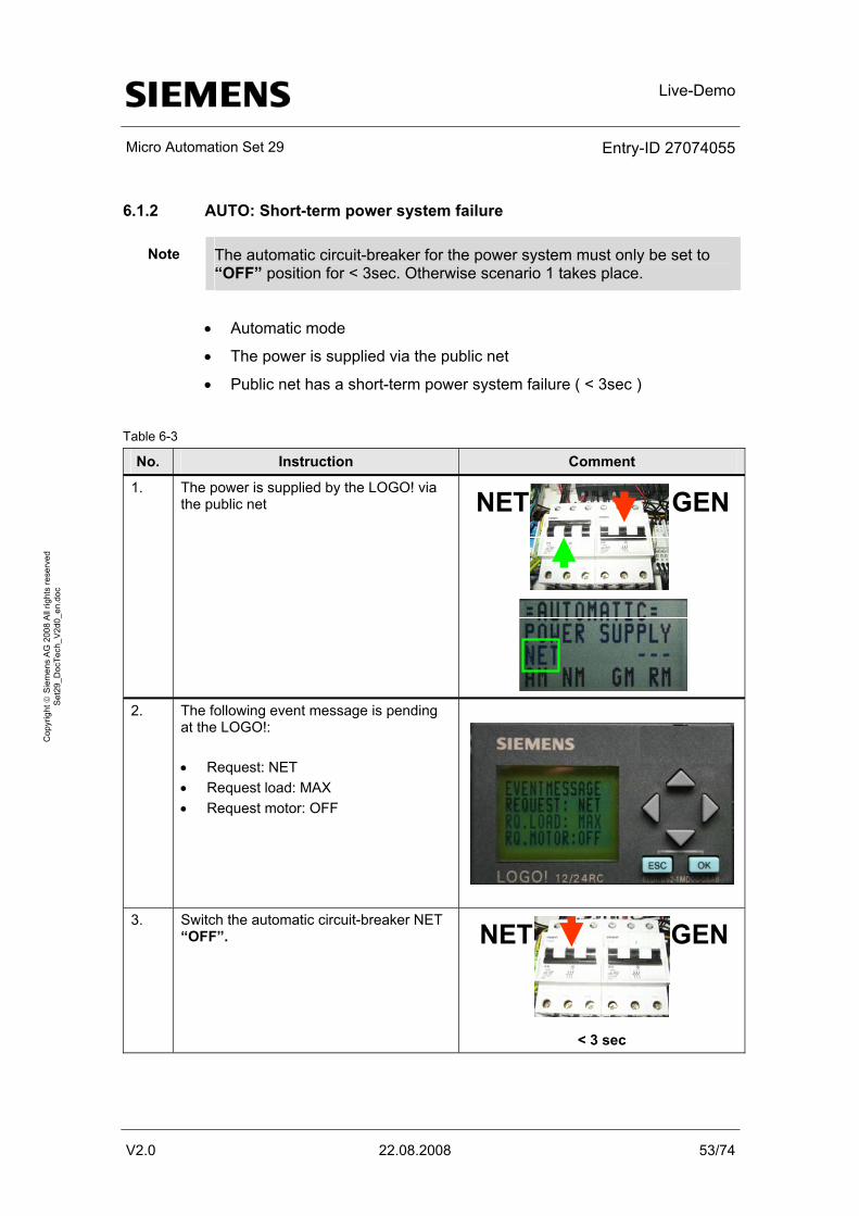
6.1.2 AUTO: Short-term power system failure
Note The automatic circuit-breaker for the power system must only be set to “OFF” position for < 3sec. Otherwise scenario 1 takes place.
• Automatic mode
• The power is supplied via the public net
• Public net has a short-term power system failure ( < 3sec )
Table 6-3
No. Instruction Comment
1. The power is supplied by the LOGO! via the public net NET GEN
2. The following event message is pending
at the LOGO!: • Request: NET • Request load: MAX • Request motor: OFF
3. Switch the automatic circuit-breaker NET
“OFF”. NET GEN
< 3 sec
Live-Demo
Micro Automation Set 29 Entry-ID 27074055
V2.0 22.08.2008 54/74
Cop
yrig
ht ©
Sie
men
s A
G 2
008
All
right
s re
serv
ed
Set
29_D
ocTe
ch_V
2d0_
en.d
oc
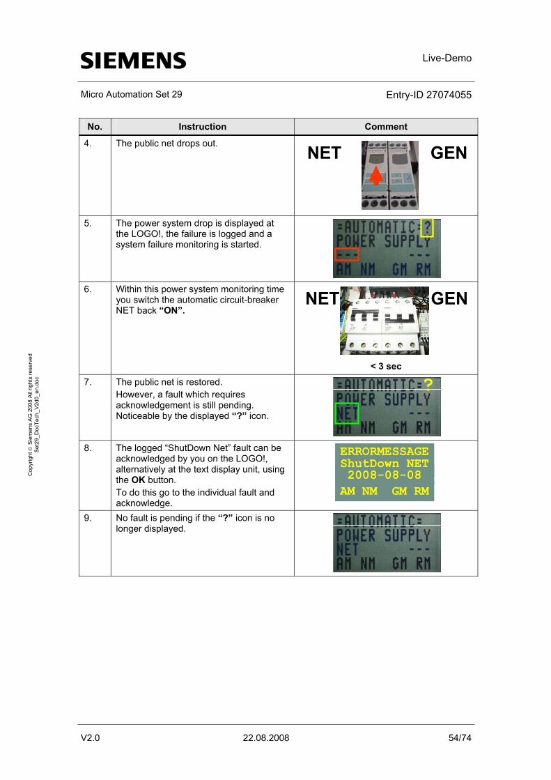
No. Instruction Comment
4. The public net drops out. NET GEN
5. The power system drop is displayed at
the LOGO!, the failure is logged and a system failure monitoring is started.
6. Within this power system monitoring time
you switch the automatic circuit-breaker NET back “ON”.
NET GEN
< 3 sec
7. The public net is restored. However, a fault which requires acknowledgement is still pending. Noticeable by the displayed “?” icon.
?
8. The logged “ShutDown Net” fault can be
acknowledged by you on the LOGO!, alternatively at the text display unit, using the OK button. To do this go to the individual fault and acknowledge.
ERRORMESSAGE
AM NM GM RM2008-08-08 ShutDown NET
9. No fault is pending if the “?” icon is no longer displayed.
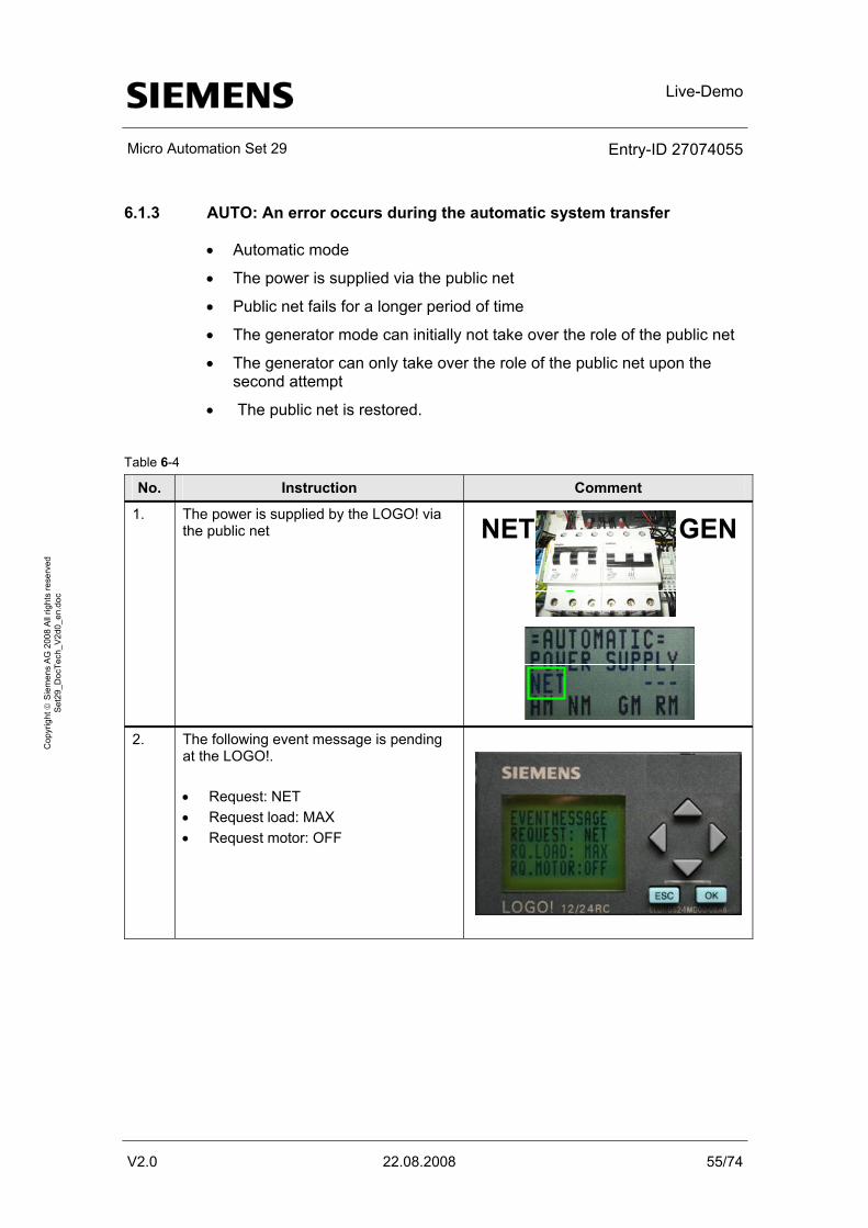
Live-Demo
Micro Automation Set 29 Entry-ID 27074055
V2.0 22.08.2008 55/74
Cop
yrig
ht ©
Sie
men
s A
G 2
008
All
right
s re
serv
ed
Set
29_D
ocTe
ch_V
2d0_
en.d
oc
6.1.3 AUTO: An error occurs during the automatic system transfer
• Automatic mode
• The power is supplied via the public net
• Public net fails for a longer period of time
• The generator mode can initially not take over the role of the public net
• The generator can only take over the role of the public net upon the second attempt
• The public net is restored.
Table 6-4
No. Instruction Comment
1. The power is supplied by the LOGO! via the public net
NET GEN
2. The following event message is pending
at the LOGO!. • Request: NET • Request load: MAX • Request motor: OFF
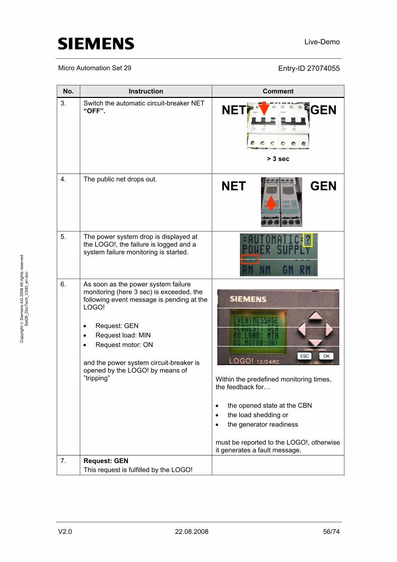
Live-Demo
Micro Automation Set 29 Entry-ID 27074055
V2.0 22.08.2008 56/74
Cop
yrig
ht ©
Sie
men
s A
G 2
008
All
right
s re
serv
ed
Set
29_D
ocTe
ch_V
2d0_
en.d
oc
No. Instruction Comment
3. Switch the automatic circuit-breaker NET “OFF”. NET GEN
> 3 sec
4. The public net drops out.
NET GEN
5. The power system drop is displayed at
the LOGO!, the failure is logged and a system failure monitoring is started.
6. As soon as the power system failure
monitoring (here 3 sec) is exceeded, the following event message is pending at the LOGO! • Request: GEN • Request load: MIN • Request motor: ON and the power system circuit-breaker is opened by the LOGO! by means of ”tripping”
Within the predefined monitoring times, the feedback for… • the opened state at the CBN • the load shedding or • the generator readiness must be reported to the LOGO!, otherwise it generates a fault message.
7. Request: GEN This request is fulfilled by the LOGO!
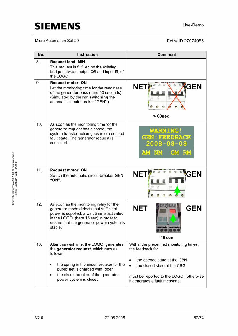
Live-Demo
Micro Automation Set 29 Entry-ID 27074055
V2.0 22.08.2008 57/74
Cop
yrig
ht ©
Sie
men
s A
G 2
008
All
right
s re
serv
ed
Set
29_D
ocTe
ch_V
2d0_
en.d
oc
No. Instruction Comment
8. Request load: MIN This request is fulfilled by the existing bridge between output Q8 and input I5, of the LOGO!
9. Request motor: ON Let the monitoring time for the readiness of the generator pass (here 60 seconds). (Simulated by the not switching the automatic circuit-breaker “GEN”.)
NET GEN
> 60sec
10. As soon as the monitoring time for the generator request has elapsed, the system transfer action goes into a defined fault state. The generator request is cancelled.
WARNING!
AM NM GM RM2008-08-08 GEN:FEEDBACK
11. Request motor: ON Switch the automatic circuit-breaker GEN “ON”.
NET GEN
12. As soon as the monitoring relay for the
generator mode detects that sufficient power is supplied, a wait time is activated in the LOGO! (here 15 sec) in order to ensure that the generator power system is stable.
NET GEN
15 sec
13. After this wait time, the LOGO! generates the generator request, which runs as follows: • the spring in the circuit-breaker for the
public net is charged with “open” • the circuit-breaker of the generator
power system is closed
Within the predefined monitoring times, the feedback for • the opened state at the CBN • the closed state at the CBG must be reported to the LOGO!, otherwise it generates a fault message.
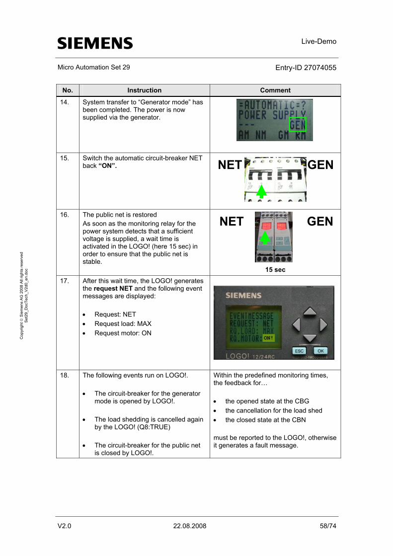
Live-Demo
Micro Automation Set 29 Entry-ID 27074055
V2.0 22.08.2008 58/74
Cop
yrig
ht ©
Sie
men
s A
G 2
008
All
right
s re
serv
ed
Set
29_D
ocTe
ch_V
2d0_
en.d
oc
No. Instruction Comment
14. System transfer to “Generator mode” has been completed. The power is now supplied via the generator.
15. Switch the automatic circuit-breaker NET back “ON”. NET GEN
16. The public net is restored
As soon as the monitoring relay for the power system detects that a sufficient voltage is supplied, a wait time is activated in the LOGO! (here 15 sec) in order to ensure that the public net is stable.
NET GEN
15 sec
17. After this wait time, the LOGO! generates the request NET and the following event messages are displayed: • Request: NET • Request load: MAX • Request motor: ON
ON!
18. The following events run on LOGO!.
• The circuit-breaker for the generator
mode is opened by LOGO!. • The load shedding is cancelled again
by the LOGO! (Q8:TRUE) • The circuit-breaker for the public net
is closed by LOGO!.
Within the predefined monitoring times, the feedback for… • the opened state at the CBG • the cancellation for the load shed • the closed state at the CBN must be reported to the LOGO!, otherwise it generates a fault message.
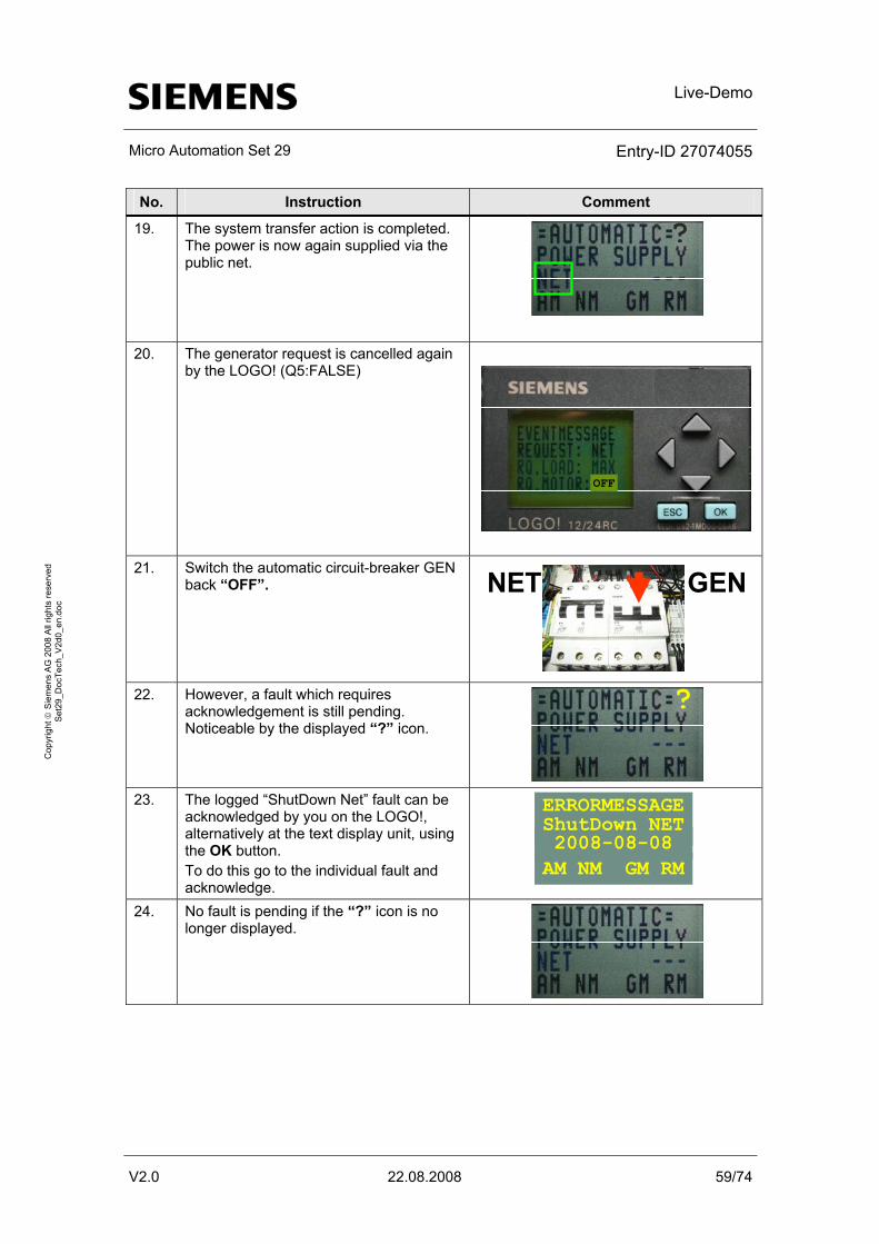
Live-Demo
Micro Automation Set 29 Entry-ID 27074055
V2.0 22.08.2008 59/74
Cop
yrig
ht ©
Sie
men
s A
G 2
008
All
right
s re
serv
ed
Set
29_D
ocTe
ch_V
2d0_
en.d
oc
No. Instruction Comment
19. The system transfer action is completed. The power is now again supplied via the public net.
?
20. The generator request is cancelled again by the LOGO! (Q5:FALSE)
OFF
21. Switch the automatic circuit-breaker GEN
back “OFF”. NET GEN
22. However, a fault which requires
acknowledgement is still pending. Noticeable by the displayed “?” icon.
?
23. The logged “ShutDown Net” fault can be
acknowledged by you on the LOGO!, alternatively at the text display unit, using the OK button. To do this go to the individual fault and acknowledge.
ERRORMESSAGE
AM NM GM RM2008-08-08 ShutDown NET
24. No fault is pending if the “?” icon is no longer displayed.
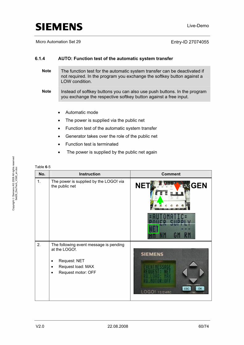
Live-Demo
Micro Automation Set 29 Entry-ID 27074055
V2.0 22.08.2008 60/74
Cop
yrig
ht ©
Sie
men
s A
G 2
008
All
right
s re
serv
ed
Set
29_D
ocTe
ch_V
2d0_
en.d
oc
6.1.4 AUTO: Function test of the automatic system transfer
Note The function test for the automatic system transfer can be deactivated if not required. In the program you exchange the softkey button against a LOW condition.
Note Instead of softkey buttons you can also use push buttons. In the program you exchange the respective softkey button against a free input.
• Automatic mode
• The power is supplied via the public net
• Function test of the automatic system transfer
• Generator takes over the role of the public net
• Function test is terminated
• The power is supplied by the public net again
Table 6-5
No. Instruction Comment
1. The power is supplied by the LOGO! via the public net
NET GEN
2. The following event message is pending
at the LOGO!. • Request: NET • Request load: MAX • Request motor: OFF
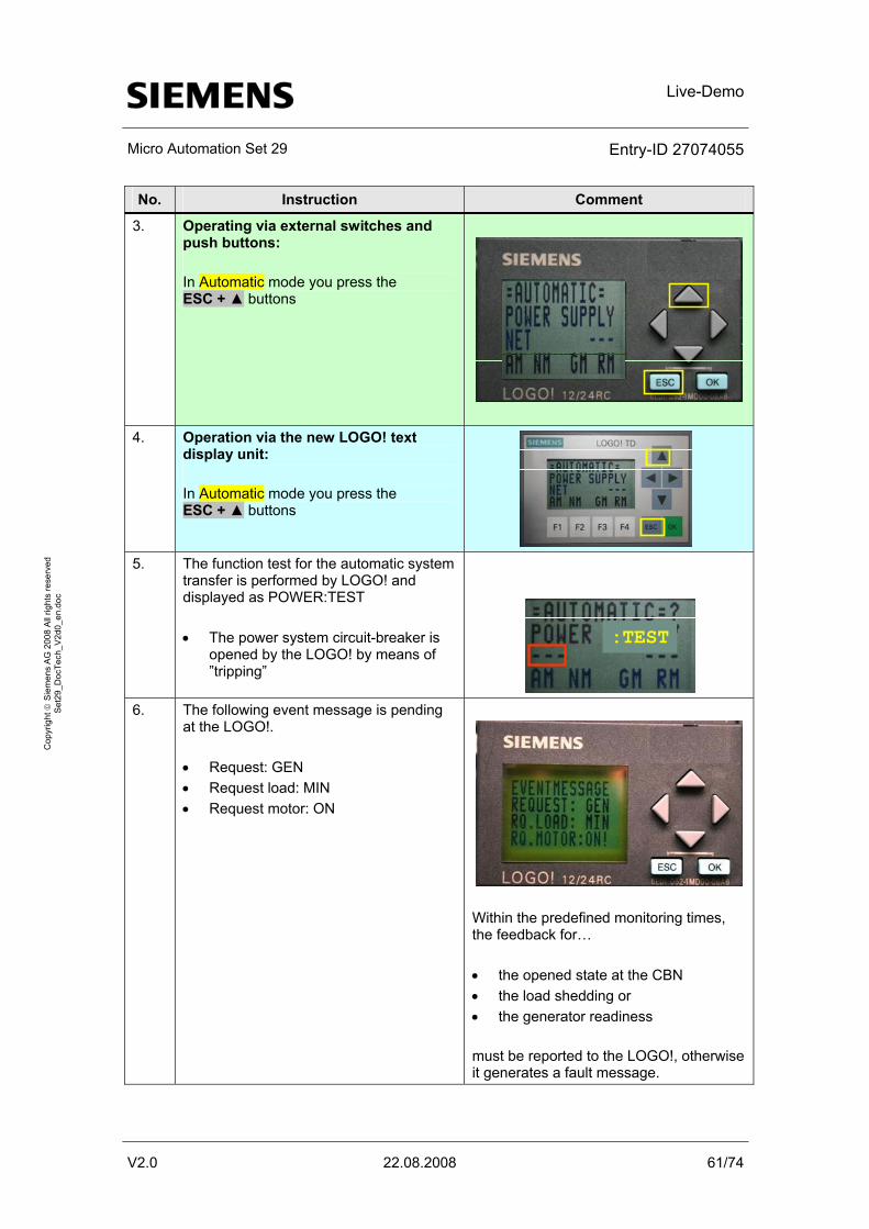
Live-Demo
Micro Automation Set 29 Entry-ID 27074055
V2.0 22.08.2008 61/74
Cop
yrig
ht ©
Sie
men
s A
G 2
008
All
right
s re
serv
ed
Set
29_D
ocTe
ch_V
2d0_
en.d
oc
No. Instruction Comment
3. Operating via external switches and push buttons: In Automatic mode you press the ESC + ▲ buttons
4. Operation via the new LOGO! text
display unit: In Automatic mode you press the ESC + ▲ buttons
5. The function test for the automatic system
transfer is performed by LOGO! and displayed as POWER:TEST • The power system circuit-breaker is
opened by the LOGO! by means of ”tripping”
:TEST
6. The following event message is pending
at the LOGO!. • Request: GEN • Request load: MIN • Request motor: ON
Within the predefined monitoring times, the feedback for… • the opened state at the CBN • the load shedding or • the generator readiness must be reported to the LOGO!, otherwise it generates a fault message.
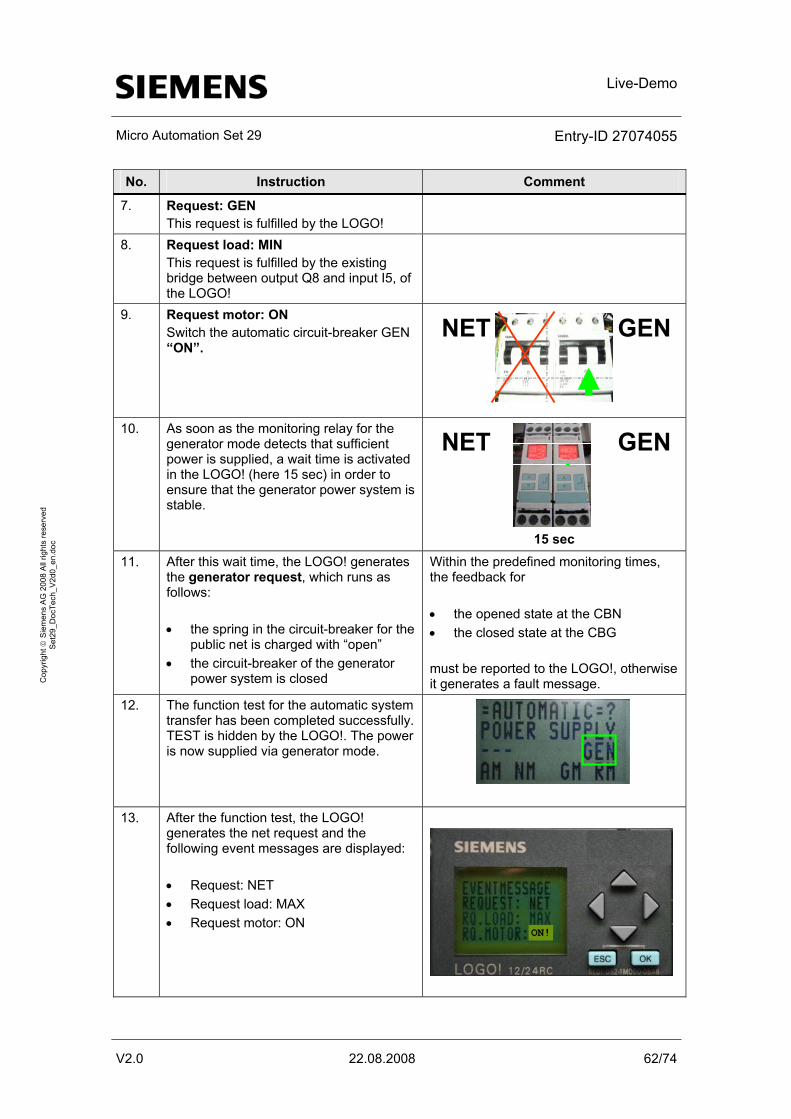
Live-Demo
Micro Automation Set 29 Entry-ID 27074055
V2.0 22.08.2008 62/74
Cop
yrig
ht ©
Sie
men
s A
G 2
008
All
right
s re
serv
ed
Set
29_D
ocTe
ch_V
2d0_
en.d
oc
No. Instruction Comment
7. Request: GEN This request is fulfilled by the LOGO!
8. Request load: MIN This request is fulfilled by the existing bridge between output Q8 and input I5, of the LOGO!
9. Request motor: ON Switch the automatic circuit-breaker GEN “ON”.
NET GEN
10. As soon as the monitoring relay for the
generator mode detects that sufficient power is supplied, a wait time is activated in the LOGO! (here 15 sec) in order to ensure that the generator power system is stable.
NET GEN
15 sec
11. After this wait time, the LOGO! generates the generator request, which runs as follows: • the spring in the circuit-breaker for the
public net is charged with “open” • the circuit-breaker of the generator
power system is closed
Within the predefined monitoring times, the feedback for • the opened state at the CBN • the closed state at the CBG must be reported to the LOGO!, otherwise it generates a fault message.
12. The function test for the automatic system transfer has been completed successfully. TEST is hidden by the LOGO!. The power is now supplied via generator mode.
13. After the function test, the LOGO! generates the net request and the following event messages are displayed: • Request: NET • Request load: MAX • Request motor: ON
ON!
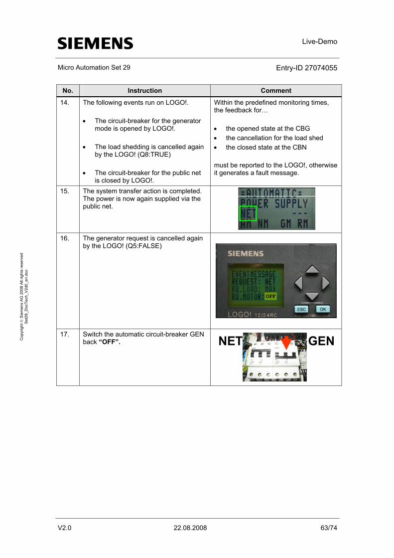
Live-Demo
Micro Automation Set 29 Entry-ID 27074055
V2.0 22.08.2008 63/74
Cop
yrig
ht ©
Sie
men
s A
G 2
008
All
right
s re
serv
ed
Set
29_D
ocTe
ch_V
2d0_
en.d
oc
No. Instruction Comment
14. The following events run on LOGO!. • The circuit-breaker for the generator
mode is opened by LOGO!. • The load shedding is cancelled again
by the LOGO! (Q8:TRUE) • The circuit-breaker for the public net
is closed by LOGO!.
Within the predefined monitoring times, the feedback for… • the opened state at the CBG • the cancellation for the load shed • the closed state at the CBN must be reported to the LOGO!, otherwise it generates a fault message.
15. The system transfer action is completed. The power is now again supplied via the public net.
16. The generator request is cancelled again
by the LOGO! (Q5:FALSE)
OFF
17. Switch the automatic circuit-breaker GEN
back “OFF”. NET GEN
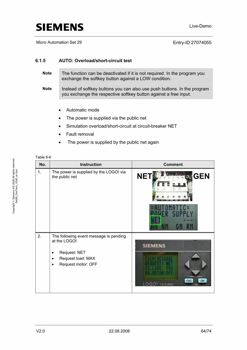
Live-Demo
Micro Automation Set 29 Entry-ID 27074055
V2.0 22.08.2008 64/74
Cop
yrig
ht ©
Sie
men
s A
G 2
008
All
right
s re
serv
ed
Set
29_D
ocTe
ch_V
2d0_
en.d
oc
6.1.5 AUTO: Overload/short-circuit test
Note The function can be deactivated if it is not required. In the program you exchange the softkey button against a LOW condition.
Note Instead of softkey buttons you can also use push buttons. In the program you exchange the respective softkey button against a free input.
• Automatic mode
• The power is supplied via the public net
• Simulation overload/short-circuit at circuit-breaker NET
• Fault removal
• The power is supplied by the public net again
Table 6-6
No. Instruction Comment
1. The power is supplied by the LOGO! via the public net NET GEN
2. The following event message is pending
at the LOGO!. • Request: NET • Request load: MAX • Request motor: OFF
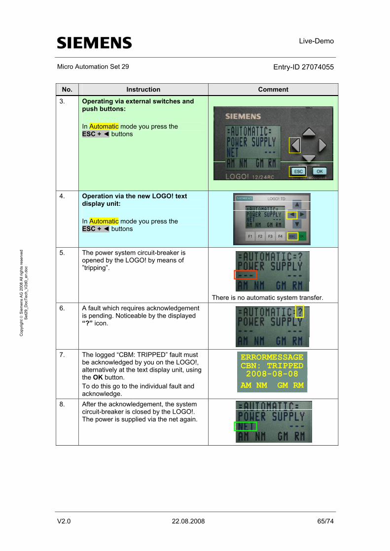
Live-Demo
Micro Automation Set 29 Entry-ID 27074055
V2.0 22.08.2008 65/74
Cop
yrig
ht ©
Sie
men
s A
G 2
008
All
right
s re
serv
ed
Set
29_D
ocTe
ch_V
2d0_
en.d
oc
No. Instruction Comment
3. Operating via external switches and push buttons: In Automatic mode you press the ESC + ◄ buttons
4. Operation via the new LOGO! text
display unit: In Automatic mode you press the ESC + ◄ buttons
5. The power system circuit-breaker is
opened by the LOGO! by means of ”tripping”.
There is no automatic system transfer.
6. A fault which requires acknowledgement is pending. Noticeable by the displayed “?” icon.
7. The logged “CBM: TRIPPED” fault must
be acknowledged by you on the LOGO!, alternatively at the text display unit, using the OK button. To do this go to the individual fault and acknowledge.
ERRORMESSAGE
AM NM GM RM2008-08-08 CBN: TRIPPED
8. After the acknowledgement, the system circuit-breaker is closed by the LOGO!. The power is supplied via the net again.

Live-Demo
Micro Automation Set 29 Entry-ID 27074055
V2.0 22.08.2008 66/74
Cop
yrig
ht ©
Sie
men
s A
G 2
008
All
right
s re
serv
ed
Set
29_D
ocTe
ch_V
2d0_
en.d
oc
6.1.6 SERVICE: Service mode
Note In this mode the LOGO! is inactive. There are no undesired actions by the LOGO!.
Table 6-7
No. Instruction Comment
1. Operating via external switches and push buttons: Set knob switch “S1” to “Service” mode and knob switch “S2” to selection “0”.
S1 S2Auto
Serv Man Netz 0Gen
2. Operation via the new LOGO! text
display unit: In Automatic mode you press the ESC + ▼ buttons
3. You are now in service mode. In this
mode the LOGO! is inactive and there are no undesired actions.
4. Provoke a power system failure. Switch
the automatic circuit-breaker NET “OFF”. NET GEN
5. The public net drops out. NET GEN
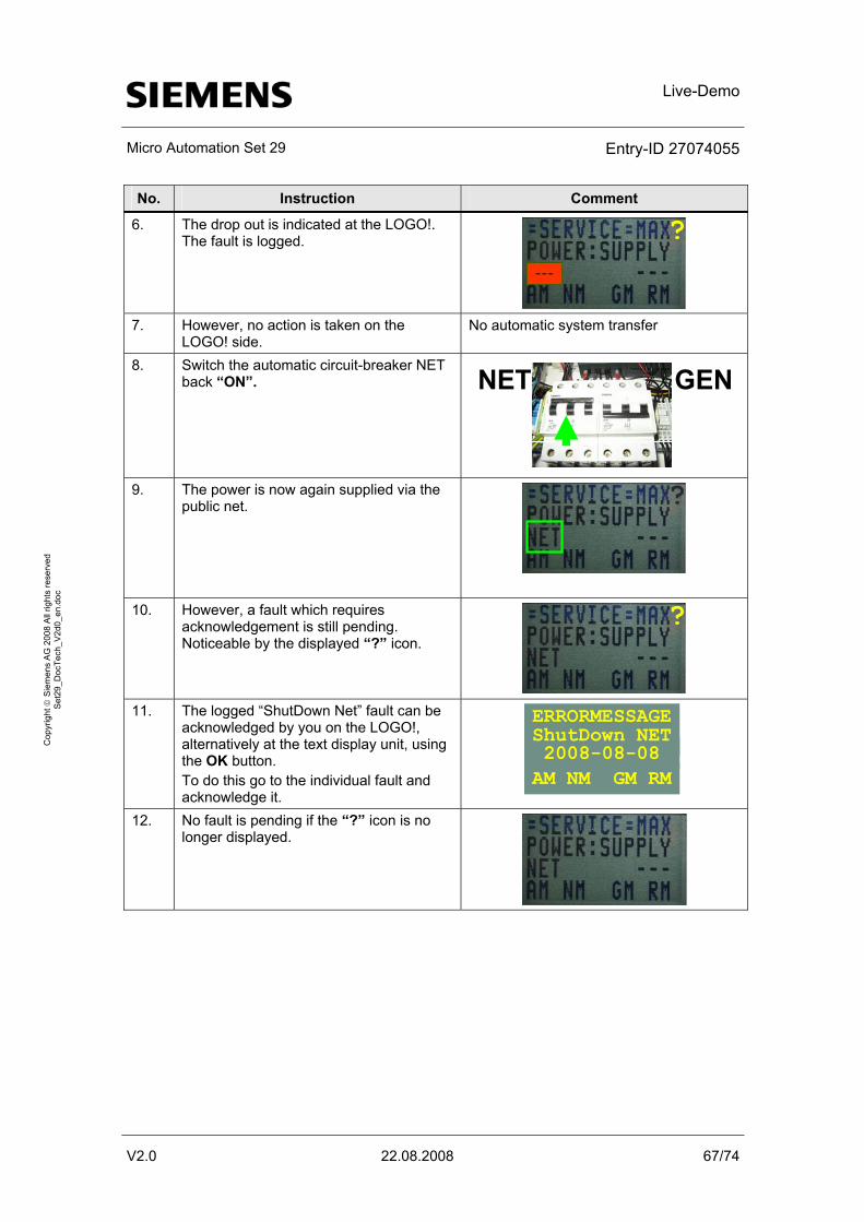
Live-Demo
Micro Automation Set 29 Entry-ID 27074055
V2.0 22.08.2008 67/74
Cop
yrig
ht ©
Sie
men
s A
G 2
008
All
right
s re
serv
ed
Set
29_D
ocTe
ch_V
2d0_
en.d
oc
No. Instruction Comment
6. The drop out is indicated at the LOGO!. The fault is logged. ?
---
7. However, no action is taken on the
LOGO! side. No automatic system transfer
8. Switch the automatic circuit-breaker NET back “ON”. NET GEN
9. The power is now again supplied via the
public net. ?
10. However, a fault which requires acknowledgement is still pending. Noticeable by the displayed “?” icon.
?
11. The logged “ShutDown Net” fault can be
acknowledged by you on the LOGO!, alternatively at the text display unit, using the OK button. To do this go to the individual fault and acknowledge it.
ERRORMESSAGE
AM NM GM RM2008-08-08 ShutDown NET
12. No fault is pending if the “?” icon is no longer displayed.
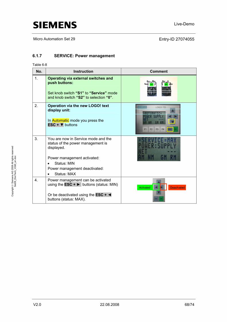
Live-Demo
Micro Automation Set 29 Entry-ID 27074055
V2.0 22.08.2008 68/74
Cop
yrig
ht ©
Sie
men
s A
G 2
008
All
right
s re
serv
ed
Set
29_D
ocTe
ch_V
2d0_
en.d
oc
6.1.7 SERVICE: Power management
Table 6-8
No. Instruction Comment
1. Operating via external switches and push buttons: Set knob switch “S1” to “Service” mode and knob switch “S2” to selection “0”.
S1 S2Auto
Serv Man Netz 0Gen
2. Operation via the new LOGO! text
display unit: In Automatic mode you press the ESC + ▼ buttons
3. You are now in Service mode and the
status of the power management is displayed. Power management activated: • Status: MIN Power management deactivated: • Status: MAX
4. Power management can be activated using the ESC + ► buttons (status: MIN) Or be deactivated using the ESC + ◄ buttons (status: MAX).
DeactivatedActivated
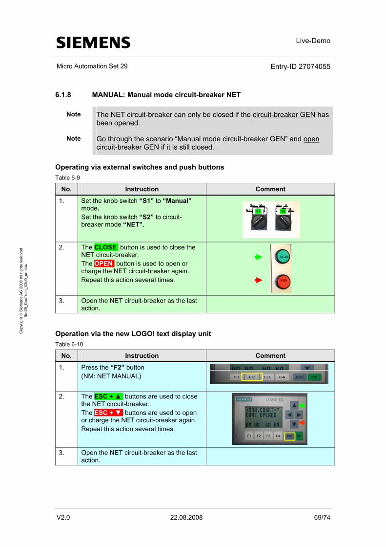
Live-Demo
Micro Automation Set 29 Entry-ID 27074055
V2.0 22.08.2008 69/74
Cop
yrig
ht ©
Sie
men
s A
G 2
008
All
right
s re
serv
ed
Set
29_D
ocTe
ch_V
2d0_
en.d
oc
6.1.8 MANUAL: Manual mode circuit-breaker NET
Note The NET circuit-breaker can only be closed if the circuit-breaker GEN has been opened.
Note Go through the scenario “Manual mode circuit-breaker GEN” and open circuit-breaker GEN if it is still closed.
Operating via external switches and push buttons Table 6-9
No. Instruction Comment
1. Set the knob switch “S1” to “Manual” mode. Set the knob switch “S2” to circuit-breaker mode “NET”.
S1 S2Auto
Serv Man Netz 0Gen
2. The CLOSE button is used to close the
NET circuit-breaker. The OPEN button is used to open or charge the NET circuit-breaker again. Repeat this action several times. OPEN
CLOSE
3. Open the NET circuit-breaker as the last
action.
Operation via the new LOGO! text display unit Table 6-10
No. Instruction Comment
1. Press the “F2” button (NM: NET MANUAL)
2. The ESC + ▲ buttons are used to close
the NET circuit-breaker. The ESC + ▼ buttons are used to open or charge the NET circuit-breaker again. Repeat this action several times.
3. Open the NET circuit-breaker as the last
action.
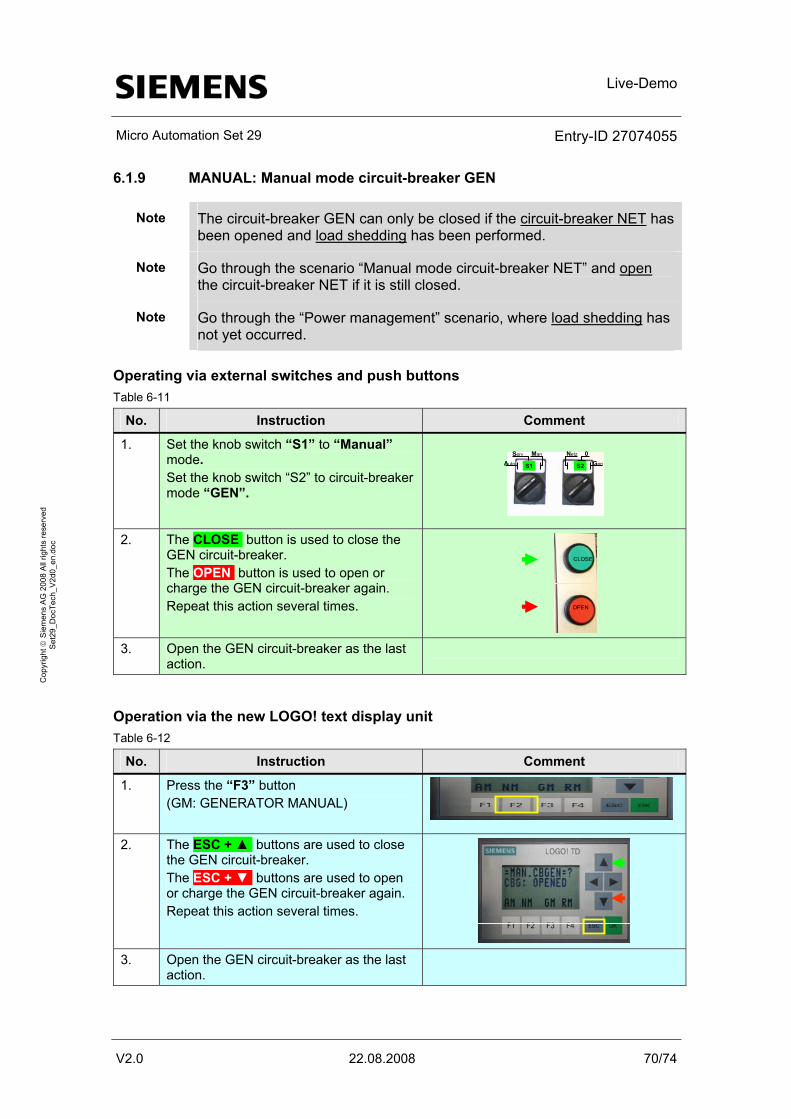
Live-Demo
Micro Automation Set 29 Entry-ID 27074055
V2.0 22.08.2008 70/74
Cop
yrig
ht ©
Sie
men
s A
G 2
008
All
right
s re
serv
ed
Set
29_D
ocTe
ch_V
2d0_
en.d
oc
6.1.9 MANUAL: Manual mode circuit-breaker GEN
Note The circuit-breaker GEN can only be closed if the circuit-breaker NET has been opened and load shedding has been performed.
Note Go through the scenario “Manual mode circuit-breaker NET” and open the circuit-breaker NET if it is still closed.
Note Go through the “Power management” scenario, where load shedding has not yet occurred.
Operating via external switches and push buttons Table 6-11
No. Instruction Comment
1. Set the knob switch “S1” to “Manual” mode. Set the knob switch “S2” to circuit-breaker mode “GEN”.
S1 S2Auto
Serv Man Netz 0Gen
2. The CLOSE button is used to close the
GEN circuit-breaker. The OPEN button is used to open or charge the GEN circuit-breaker again. Repeat this action several times. OPEN
CLOSE
3. Open the GEN circuit-breaker as the last
action.
Operation via the new LOGO! text display unit Table 6-12
No. Instruction Comment
1. Press the “F3” button (GM: GENERATOR MANUAL)
2. The ESC + ▲ buttons are used to close
the GEN circuit-breaker. The ESC + ▼ buttons are used to open or charge the GEN circuit-breaker again. Repeat this action several times.
3. Open the GEN circuit-breaker as the last
action.
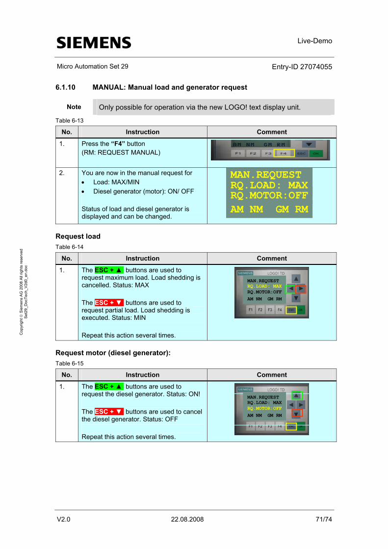
Live-Demo
Micro Automation Set 29 Entry-ID 27074055
V2.0 22.08.2008 71/74
Cop
yrig
ht ©
Sie
men
s A
G 2
008
All
right
s re
serv
ed
Set
29_D
ocTe
ch_V
2d0_
en.d
oc
6.1.10 MANUAL: Manual load and generator request
Note Only possible for operation via the new LOGO! text display unit.
Table 6-13
No. Instruction Comment
1. Press the “F4” button (RM: REQUEST MANUAL)
2. You are now in the manual request for
• Load: MAX/MIN • Diesel generator (motor): ON/ OFF Status of load and diesel generator is displayed and can be changed.
MAN.REQUEST
AM NM GM RMRQ.MOTOR:OFFRQ.LOAD: MAX
Request load Table 6-14
No. Instruction Comment
1. The ESC + ▲ buttons are used to request maximum load. Load shedding is cancelled. Status: MAX The ESC + ▼ buttons are used to request partial load. Load shedding is executed. Status: MIN Repeat this action several times.
MAN.REQUEST
AM NM GM RMRQ.MOTOR:OFFRQ.LOAD: MAX
Request motor (diesel generator): Table 6-15
No. Instruction Comment
1. The ESC + ▲ buttons are used to request the diesel generator. Status: ON! The ESC + ▼ buttons are used to cancel the diesel generator. Status: OFF Repeat this action several times.
MAN.REQUEST
AM NM GM RMRQ.MOTOR:OFFRQ.LOAD: MAX
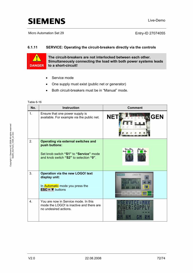
Live-Demo
Micro Automation Set 29 Entry-ID 27074055
V2.0 22.08.2008 72/74
Cop
yrig
ht ©
Sie
men
s A
G 2
008
All
right
s re
serv
ed
Set
29_D
ocTe
ch_V
2d0_
en.d
oc
6.1.11 SERVICE: Operating the circuit-breakers directly via the controls
! DANGER
The circuit-breakers are not interlocked between each other. Simultaneously connecting the load with both power systems leads to a short-circuit!
• Service mode
• One supply must exist (public net or generator)
• Both circuit-breakers must be in “Manual” mode.
Table 6-16
No. Instruction Comment
1. Ensure that one power supply is available. For example via the public net. NET GEN
2. Operating via external switches and
push buttons: Set knob switch “S1” to “Service” mode and knob switch “S2” to selection “0”.
S1 S2Auto
Serv Man Netz 0Gen
3. Operation via the new LOGO! text
display unit: In Automatic mode you press the ESC + ▼ buttons
4. You are now in Service mode. In this
mode the LOGO! is inactive and there are no undesired actions.
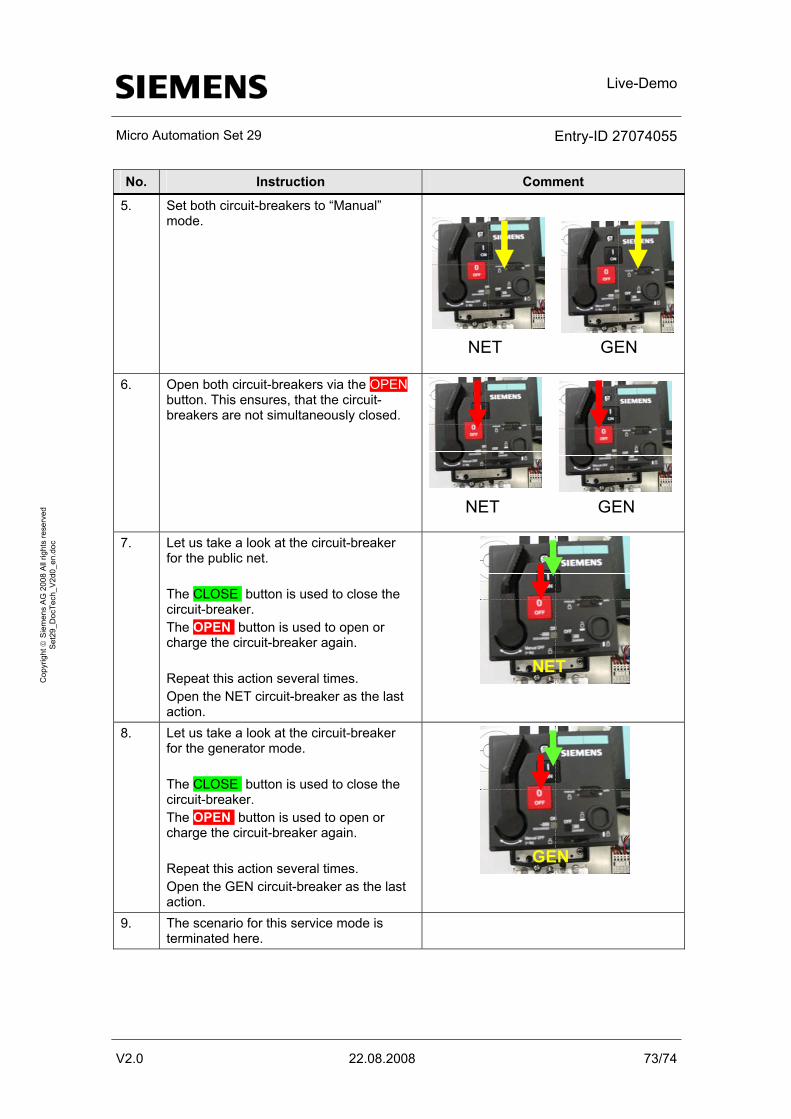
Live-Demo
Micro Automation Set 29 Entry-ID 27074055
V2.0 22.08.2008 73/74
Cop
yrig
ht ©
Sie
men
s A
G 2
008
All
right
s re
serv
ed
Set
29_D
ocTe
ch_V
2d0_
en.d
oc
No. Instruction Comment
5. Set both circuit-breakers to “Manual” mode.
NET GEN
6. Open both circuit-breakers via the OPEN button. This ensures, that the circuit-breakers are not simultaneously closed.
NET GEN
7. Let us take a look at the circuit-breaker for the public net. The CLOSE button is used to close the circuit-breaker. The OPEN button is used to open or charge the circuit-breaker again. Repeat this action several times. Open the NET circuit-breaker as the last action.
NET
8. Let us take a look at the circuit-breaker for the generator mode. The CLOSE button is used to close the circuit-breaker. The OPEN button is used to open or charge the circuit-breaker again. Repeat this action several times. Open the GEN circuit-breaker as the last action.
GEN
9. The scenario for this service mode is terminated here.

Technical Data
Micro Automation Set 29 Entry-ID 27074055
V2.0 22.08.2008 74/74
Cop
yrig
ht ©
Sie
men
s A
G 2
008
All
right
s re
serv
ed
Set
29_D
ocTe
ch_V
2d0_
en.d
oc
7 Technical Data
7.1 LOGO!
Table 7-1
Criterion Technical data Additional note
LOGO! logic module (12/24RC)
SV/E/A: DC12/24V / DC12/24V / relay 8DE (2AE 0..10V)/4DA,
Logic module with display and keybord 200 blocks Modular extendible
LOGO! DM8 24R expansion module
SV/E/A: AC/DC 24V / AC/DC 24V PNP and NPN / relay 4DE/4DA
2TE
7.2 SENTRON
Table 7-2
Criterion Technical data Additional note
SENTRON circuit-breaker VL 160N
ICU=40kA, 415V AC 3-pole, shunt release 24V AC/DC auxiliary mounting set 2 HS (1S+1OE)
System protection over-current trigger TM, LI IN=50A, rated current IR=40...50A, Overload protection II=300...600A, short-circuit protection, protection
Motorized operating mechanism with spring energy store
220...250V AC/DC
7.3 SIRIUS
Table 7-3
Criterion Technical data Additional note
SIRIUS monitoring relay 3UG4
PHASE FAILURE 3X 160 TO 690V AC 50 TO 60 HZ UNDER AND OVER VOLTAGE 160-690V HYSTERESE 1-20V SWITCH-OFF DELAY 0-20S ASYMMETRY 0-20% 1W FOR PHASE CORRECTION 1 W FOR NETWORK ERROR
DIGITAL MONITORING RELAY FOR THREE-PHASE NET VOLTAGE AUT. CORRECTION THREE-PHASE SEQUENCE SCREW-TYPE CONNECTION
Contactor 2S+2OE, DC 24V SCREW-TYPE CONNECTION Quenching circuit RC-ELEMENT AC 24...48V, DC
24...70V OVER-VOLTAGE LIMITER