Transfer Gear Pumps KF4.. - KRACHT CORP. · Transfer gear pumps KF are distinguished especially ......
44
Transfer Gear Pumps KF 4...112
Transcript of Transfer Gear Pumps KF4.. - KRACHT CORP. · Transfer gear pumps KF are distinguished especially ......

Transfer Gear Pumps
KF 4...112
Transfer Gear Pumps KF 4...112
KRACHT GmbH · Gewerbestr. 20 · 58791 Werdohl, Germany · fon +49(0)23 92/935-0 · fax +49(0)23 92/935 209 · mail [email protected] · web www.kracht.eu2

KRACHT GmbH · Gewerbestr. 20 · 58791 Werdohl, Germany · fon +49(0)23 92/935-0 · fax +49(0)23 92/935 209 · mail [email protected] · web www.kracht.eu 3
Transfer Gear Pumps KF 4...112
Technical Data
Page
Applications / Suitable fluids . . . . . . . . . . . . . . . . . . . . . . . . . . . . . . . . . . . . . . . . . . . . . . . . . . . . . . . . . . . 4
Construction . . . . . . . . . . . . . . . . . . . . . . . . . . . . . . . . . . . . . . . . . . . . . . . . . . . . . . . . . . . . . . . . . . . . . . 5
Variants / Direction of rotation . . . . . . . . . . . . . . . . . . . . . . . . . . . . . . . . . . . . . . . . . . . . . . . . . . . . . . . . . 6
ATEX version . . . . . . . . . . . . . . . . . . . . . . . . . . . . . . . . . . . . . . . . . . . . . . . . . . . . . . . . . . . . . . . . . . . . . . 7
Materials / Characteristics . . . . . . . . . . . . . . . . . . . . . . . . . . . . . . . . . . . . . . . . . . . . . . . . . . . . . . . . . . . . . 8
Shaft end seals / Variants . . . . . . . . . . . . . . . . . . . . . . . . . . . . . . . . . . . . . . . . . . . . . . . . . . . . . . . . . . . . . 9 – 10
Version noise optimized . . . . . . . . . . . . . . . . . . . . . . . . . . . . . . . . . . . . . . . . . . . . . . . . . . . . . . . . . . . . . . 11
Type key . . . . . . . . . . . . . . . . . . . . . . . . . . . . . . . . . . . . . . . . . . . . . . . . . . . . . . . . . . . . . . . . . . . . . . . . . . 12
Technical data . . . . . . . . . . . . . . . . . . . . . . . . . . . . . . . . . . . . . . . . . . . . . . . . . . . . . . . . . . . . . . . . . . . . . 13
Discharge flow / Input power . . . . . . . . . . . . . . . . . . . . . . . . . . . . . . . . . . . . . . . . . . . . . . . . . . . . . . . . . . 14 – 15
Dimension Sheets
Flange-mounting version with pipe thread . . . . . . . . . . . . . . . . . . . . . . . . . . . Nominal size 4 – 25 . . . 16
Flange-mounting version with SAE 3⁄4 bzw. 1-connection (Special No. 158) . . . Nominal size 4 – 25 . . . 17
Flange-mounting version with SAE 11⁄2-connection . . . . . . . . . . . . . . . . . . . . Nominal size 32 – 80 . . . 18
Flange-mounting version with SAE 2-connection (Special No. 232) . . . . . . . . . Nominal size 50 – 80 . . . 19
Flange-mounting version with SAE 2-connection . . . . . . . . . . . . . . . . . . . . . . Nominal size 100 /112 . . . 20
Flange-mounting version with SAE 21⁄2-connection (Special No. 232) . . . . . . . Nominal size 100 /112 . . . 21
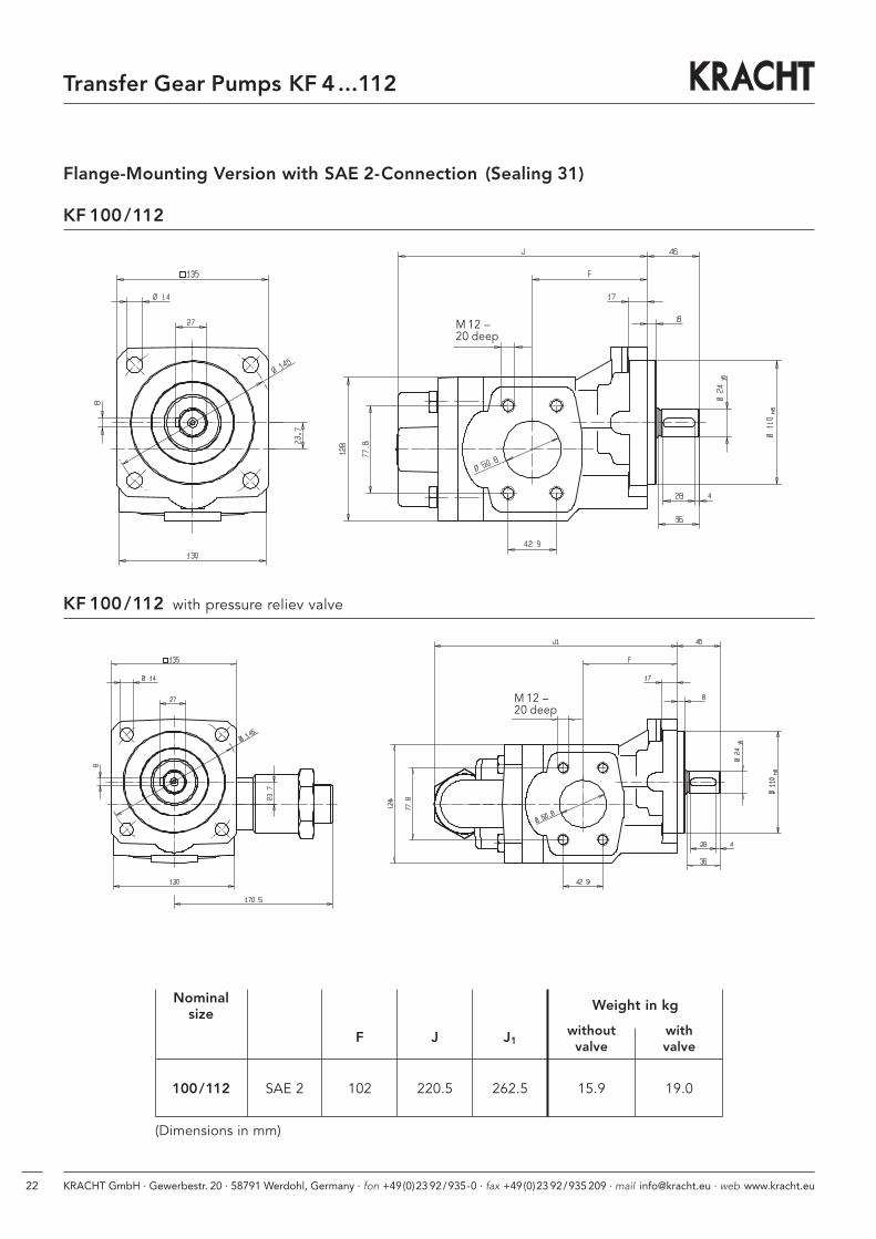
Flange-mounting version with SAE 2-connection (Sealing 31) . . . . . . . . . . . . . Nominal size 100 /112 . . . 22
Flange-mounting version with SAE 21⁄2-connection (Special No. 232, Sealing 31) Nominal size 100 /112 . . . 23
Pump with mounting angle, pipe thread . . . . . . . . . . . . . . . . . . . . . . . . . . . . Nominal size 4 – 25 . . . 24
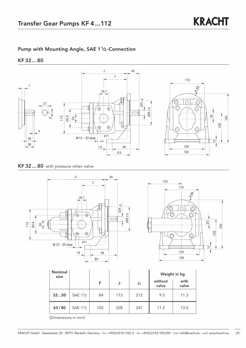
Pump with mounting angle, SAE 11⁄2-connection . . . . . . . . . . . . . . . . . . . . . . Nominal size 32 – 80 . . . 25
Flange-mounting version with universal arrangement . . . . . . . . . . . . . . . . . . Nominal size 4 – 25 . . . 26
Flange-mounting version with universal arrangement . . . . . . . . . . . . . . . . . . Nominal size 32 – 80 . . . 27
Couplings . . . . . . . . . . . . . . . . . . . . . . . . . . . . . . . . . . . . . . . . . . . . . . . . . . . . . . . . . . . . . . . . . . . . . . . . 28
Bell housing . . . . . . . . . . . . . . . . . . . . . . . . . . . . . . . . . . . . . . . . . . . . . . . . . . Nominal size 4 – 25 . . . 29
Bell housing . . . . . . . . . . . . . . . . . . . . . . . . . . . . . . . . . . . . . . . . . . . . . . . . . . Nominal size 32 – 80 . . . 30
Bell housing . . . . . . . . . . . . . . . . . . . . . . . . . . . . . . . . . . . . . . . . . . . . . . . . . . Nominal size 100 /112 . . . 31
Motor-pump assemblies with pipe thread . . . . . . . . . . . . . . . . . . . . . . . . . . . Nominal size 4 – 25 . . . 32 – 33
Motor-pump assemblies with SAE 11⁄2-connection . . . . . . . . . . . . . . . . . . . . . . . . . . . . . . Nominal size 32 – 80 . . . 34 – 35
Motor-pump assemblies with SAE 2-connection . . . . . . . . . . . . . . . . . . . . . . . . . . . . . . . . . Nominal size 100 /112 . . . 36 – 37
Threaded flange G-SAE 3⁄4 / Welding flange S-SAE 3⁄4 / Threaded flange G-SAE 1 / Welding flange S-SAE 1 . . 38
Threaded flange G-SAE 11⁄2 / Welding flange S-SAE 11⁄2 / Threaded flange G-SAE 2 / Welding flange S-SAE 2 39
Threaded flange G-SAE 21⁄2 / Welding flange S-SAE 21⁄2 / Accessory liquid seal . . . . . . . . . . . . . . . . . . . . . 40
Contents

KRACHT GmbH · Gewerbestr. 20 · 58791 Werdohl, Germany · fon +49(0)23 92/935-0 · fax +49(0)23 92/935 209 · mail [email protected] · web www.kracht.eu4
Transfer Gear Pumps KF 4...112
Applications, Suitable Fluids
Applications
Centrifuge construction,Coating machines, Compressors
Engine construction
Filling stations, Filter systems
Generator construction
Heat transfer systems, Heavy electrical machines
Lubricant manufacturers, Lubricating oil systems
Machine-building industry, Machine tools,Manufacture of apparatus,Marine engine construction,Metal-forming machines, Metering systems
Paint industry, Plain metal bearing production,Printing machines, PUR machinery
Refrigerators, Rubber and tire manufacturing
Tank plant construction,Transmission buildingTurbine construction
Vacuum machinery
Waste oil - disposal- transport- treatment
Suitable fluids
Adhesives, Antifreeze
Bore oils
Cutting oils
Diesel oils, Drawing compound
Emulsions
Fuel oils, L, EL, H
Gear oils, Grease
Hardening oils, Heat transfer media,Heavy oils, Hydraulic fluids
Isocyanate
Lubricating oils, Lacquers
Motor oils
Paint, Paraffins, Plastics, PolyolsPrinting inks, Processing oils
Resins, Rolling oils
Waste oils, Waxes

KRACHT GmbH · Gewerbestr. 20 · 58791 Werdohl, Germany · fon +49(0)23 92/935-0 · fax +49(0)23 92/935 209 · mail [email protected] · web www.kracht.eu 5
Transfer Gear Pumps KF 4...112
Getriebe
Lagerbuchse
Lagerdeckel
Gehäuse
Antriebswellenende
Wellendichtung
Construction
Product Features
Transfer gear pumps KF are used for pumping a widevariety of fluids.
Transfer gear pumps KF are distinguished especially by their wide range of variants which are assembled as required on the modular principle and also permitsubsequent upgrade.
The pumps are also suitable for media with low lubricating properties.
The standard housing sections are of grey cast iron.
The gear units are manufactured from high-strength case-hardening steel, hardened and mounted in special multi-compound plain bearing bushes.
The standard drive shaft is sealed by rotary shaft lip-type seal.
All pump sizes incorporate helical tooth system. This feature, combined with special gear geometry, results in extremely low noise levels and reduced pressure pulsation.
Working Notes
• The fluids should ensure a certain minimum lubricating properties, should not contain solids andshould be chemically compatible.
• Avoid dry operation.
• The pumps may only be operated in the specified direction of rotation, as otherwise the shaft seal will be destroyed.
• In order to prevent excessive overpressure, a safetyvalve should be provided in the system or on thepump.
• The pressure relief valve attached to the pump mayonly be used as safety valve for short-term operation.
• A separate pressure relief valve with return line tothe reservoir must be foreseen, if a partial dischargeflow has to be drained over a prolonged period.
Drive shaft end
Shaft seal
HousingGear unit
Plain bearing bushes
End cover

KRACHT GmbH · Gewerbestr. 20 · 58791 Werdohl, Germany · fon +49(0)23 92/935-0 · fax +49(0)23 92/935 209 · mail [email protected] · web www.kracht.eu6
Transfer Gear Pumps KF 4...112
Variants
• Sealing of the drive shaft:– Rotary shaft lip-type seal– Double rotary shaft lip-type seal (Quench)– Mechanical seal
• Outboard bearing to take up input drive-side radial load
• Pressure relief valve for pump and system
• Uniform discharge flow direction with changingdirection of rotation by means of flange-mountingvalve combination (universal device).
Special Design
Various shafts ends and gear units, as well as flange mounted versions, bearing alternatives, multi-stagepump combinations for your special application areavailable on request.
Our Sales engineers will be pleased to advise you.
Direction of Rotation
The following should be note for direction of rotation:
• when looking at thepump shaft end, thedirection of pumping isfrom left to right if theshaft rotates clockwise.
• when looking at thepump shaft end, the direction of pum-ping is from right to leftif the shaft rotates counterclockwise.
pump running cw
suction side pressure side pressure side suction side
pump running ccw
pump running cw
suction side pressure side pressure side suction side
pump running ccw
Without pressure relief valve
With pressure relief valve
Accessories
• Connecting flanges• Couplings• Bell housing• Quench tank• Attenuation elements
With universal device
Direction of rotation right and left
Direction of rotation consistent,see dimension sheets page 26 and 27.

KRACHT GmbH · Gewerbestr. 20 · 58791 Werdohl, Germany · fon +49(0)23 92/935-0 · fax +49(0)23 92/935 209 · mail [email protected] · web www.kracht.eu 7
Transfer Gear Pumps KF 4...112
ATEX Version
KF 4…112 KF 4…112with lip-type seal with double lip-type seal
In Ex-area max. EX II 2G T4 EX II 2G T4suitable for category EX II 2D T135 °C
Perm. working pressure – 0.4 ... + 0.5 – 0.4 ... + 0.5inlet port in bar
Perm. working pressureoutlet port in bar 25 25
Perm. viscosity in mm2/s 12 … 20 000 12 … 20 000
Max. speed in 1/min 3 000 3 000(viscosity dependent)
Perm. mounting position Horizontal or Horizontalshaft end toward bottom quencher up
Perm. media – 10 ... + 80 – 10 ... + 80temperatures in °C
Perm. ambient – 20 ... + 60 – 20 ... + 60temperatures in °C
Comments
Additional products available on request.
Vertical mounting with shaft end up on request.
In executing with outboard bearing
max. speed 1500 1/min.In dust Ex-area,
permissible only with non-conductive dusts.Dust-proof capsuling
of pump shaft and coupling required.
Not suitablefor dust-Ex.
Execution with quench feed andquencher.

KRACHT GmbH · Gewerbestr. 20 · 58791 Werdohl, Germany · fon +49(0)23 92/935-0 · fax +49(0)23 92/935 209 · mail [email protected] · web www.kracht.eu8
Transfer Gear Pumps KF 4...112
Materials
Housing and cover EN-GJL-250 (GG 25)EN-GJS-400-15 (GGG 40) on request
Gear Steel 1.7139
Plain bearing bushes DU (multi-layer friction-type bearings P 10, DP 4)Bearings free of nonferrous metal on request
Shaft end seals NBR, FKM, PTFE, EPDM (other sealing materials on request. E.g. HNBR / CR)
O-ring NBR, FKM, PTFE, EPDM (other sealing materials on request. E.g. HNBR / CR)
Characteristics
Nominal sizes 4…112 cm3 Vg = 4 / 5 / 6 / 8 /10 /12 /16 / 20 / 25 / 32 / 40 / 50 / 63 / 80 100 /112
Fitting position KF... R/L/B ... without Quench optionalKF... R/L/B ... with Quench horizontal, Quench connection aboveKF... U ... horizontal, Pressure connection above
Direction of rotation right or leftright and left
Fixing type flange (DIN ISO 3019)
Pipe connection KF 4…25 Whitworth pipe thread, SAE flangeKF 32…112 SAE flange
Drive shaft end ISO R 775 short-cylindrical
Working pressure see chart page 9suction side
Working pressure Pn 25 bar (higher pressures on request)pressure side
Speed KF 4…112 200 … 3 000 1/min
Viscosity mm2/s 12 … 20 000(dependent on pressureand rotational speed)
Fluid temperature see chart page 9
Ambient temperature Vu = -- 20 °C … 60 °C (-- 4 °F…140 °F)

KRACHT GmbH · Gewerbestr. 20 · 58791 Werdohl, Germany · fon +49(0)23 92/935-0 · fax +49(0)23 92/935 209 · mail [email protected] · web www.kracht.eu 9
Transfer Gear Pumps KF 4...112
Shaft End Seals
Sealing material Pressure Fluid temperaturesuction side *
bar °C °F
Pump with single rotary shaft lip NBR -- 0.4...1.0 -- 10...90 14...194
FKM max. 750 1/min -- 0.4...6.0max. 1000 1/min -- 0.4...5.0max. 1500 1/min -- 0.4...4.0 -- 10...150 14...302max. 2000 1/min -- 0.4...3.0max. 3000 1/min -- 0.4...2.0
FKM (low temperature) -- 0.4...0.5 -- 30 **...150 -- 22**...302
EPDM -- 0.4...0.5 -- 10...120 14...248
PTFE -- 0.4...2.0 -- 10...200 14...392
Pump with outboard bearing NBR -- 0.4...1.0 -- 10...90 14...194and single rotary shaft lip FKM max. 750 1/min -- 0.4...6.0
max. 1000 1/min -- 0.4...5.0max. 1500 1/min -- 0.4...4.0 -- 10...150 14...302max. 2000 1/min -- 0.4...3.0max. 3000 1/min -- 0.4...2.0
PTFE -- 0.4...2.0 -- 10...200 14...392
NBR -- 0.4...1.0 -- 10...90 14...194
FKM max. 750 1/min -- 0.4...6.0max. 1000 1/min -- 0.4...5.0max. 1500 1/min -- 0.4...4.0 -- 10...150 14...302max. 2000 1/min -- 0.4...3.0max. 3000 1/min -- 0.4...2.0
PTFE -- 0.4...2.0 -- 10...200 14...392
NBR -- 0.9...0.2 -- 10...90 14...194
FKM -- 0.9...0.2 -- 10...150 14...302
PTFE -- 0.9...0.2 -- 10...200 14...392
NBR -- 0.9...1.0 -- 10...90 14...194
FKM max. 750 1/min -- 0.9...6.0max. 1000 1/min -- 0.9...5.0max. 1500 1/min -- 0.9...4.0 -- 10...150 14...302max. 2000 1/min -- 0.9...3.0max. 3000 1/min -- 0.9...2.0
Pump with mechanical seal FKM -- 0.4...10.0 -- 10...150 14...302
PTFE -- 0.4...10.0 -- 10...200 14...392
EPDM -- 0.4...10.0 -- 10...120 14...248
Pump with mechanical seal and FKM -- 0.4...10.0 -- 10...150 14...302connection borehole for liquid seal(quench)
Pump with double rotary shaft sealfor vacuum operation with connection borehole for liquid seal(quench)
Pump with triple rotary shaft sealfor vacuum and normal operationwith connection borehole for liquid seal (quench)
Pump with double rotary shaft sealwith connection borehole for liquid seal (quench)
Speed: 200 – 3000 1/min
The indicated maximum values are dependent upon the remaining working conditions.
In case of universal devices, pay attention to limitation of Pe min.
Other sealing materials on request.
** short term during start-up status: -- 0.6 bar** only in connection with housing and
cover material EN-GJS-400 (GGG 40)

KRACHT GmbH · Gewerbestr. 20 · 58791 Werdohl, Germany · fon +49(0)23 92/935-0 · fax +49(0)23 92/935 209 · mail [email protected] · web www.kracht.eu10
Transfer Gear Pumps KF 4...112
Variants
Pump with single rotary shaft lip
Fixing type: F/W
Sealing materials:NBR = sealing type 1FKM = sealing type 2PTFE = sealing type 3EPDM = sealing type 9FKM low temperature
= sealing type 23/31
Pump with double rotaryshaft seal with connectionborehole for liquid seal(quench)
Fixing type: F/W
Sealing materials:NBR = sealing type 19FKM = sealing type 7PTFE = sealing type 4EPDM = sealing type 32
Pump with double rotaryshaft seal for vacuum operation with connectionborehole for liquid seal(quench)
Fixing type: F/W
Sealing materials:NBR = sealing type 19FKM = sealing type 7PTFE = sealing type 4EPDM = sealing type 32
Special number: 74
Pump with mechanical seal
Fixing type: F/W
Sealing materials:FKM = sealing type 5PTFE = sealing type 6EPDM = sealing type 20
Pump with triple rotaryshaft seal for vacuum and normal operation with connection boreholefor liquid seal (quench)
Fixing type: F/W
Sealing materials:NBR = on requestFKM = on request
Pump with mechanical sealand connection boreholefor liquid seal (quench)
Fixing type: F/W
Sealing materials:FKM = sealing type 5
Special number: 198
Pump with outboard bearing and single rotary shaft lip
Fixing type: G/X
Sealing materials:NBR = sealing type 1FKM = sealing type 2PTFE = sealing type 3
Pump without shaft sealing
Fixing type: F/W
Sealing material:FKM o-ring
= sealing type 30

KRACHT GmbH · Gewerbestr. 20 · 58791 Werdohl, Germany · fon +49(0)23 92/935-0 · fax +49(0)23 92/935 209 · mail [email protected] · web www.kracht.eu 11
Transfer Gear Pumps KF 4...112
The noise optimized pumps in the KF series are designedfor conveying media with higher proportions of air,predominantly for use as lubricating oil pumps in trans-missions. Special measures prevent the otherwisenormally increased noise present in auriferous transmissionoil. The noise levels do not exceed or only barelyexceed the measurements with non-auriferous oils.Also, there is no noise spectrum shift to higher, unplea-sant frequencies. In applications without auriferousportions in the media, it is not recommended to usethis version as it will not bring about noise reductioneffects there.
The noise optimized version of the KF pump is markedwith the special number 197 at the end of the type key.
Pumps with the special number 197 are built as pumpsin combination with an electric motor or as mountedpumps. The pump in combination with an electricmotor (Fig. 1) does not have an outboard bearing, so ithas to be driven via an elastic coupling. The mountedpump (Fig. 2) comes equipped with an outboard bearingto absorb the centrifugal forces such as those whicharise when using a flying pinion. Pumps for electricmotor drives and mounted pumps are sealed at theshaft end using a lip-type shaft seal.
Pump with single rotary shaft lip
Fixing type: F/W
Sealing materials:NBR = sealing type 1FKM = sealing type 2
Special number: 197
Fig. 1 Fig. 2
Pump with outboard bearingand single rotary shaft lip
Fixing type: G/X
Sealing materials:NBR = sealing type 1FKM = sealing type 2
Special number: 197
The noise optimized version is also available in a ductilecast iron version. We can supply these pumps in theATEX version also.
Note
Dimensions conformable standard pumps
KF 4 ...112 noise optimized

KRACHT GmbH · Gewerbestr. 20 · 58791 Werdohl, Germany · fon +49(0)23 92/935-0 · fax +49(0)23 92/935 209 · mail [email protected] · web www.kracht.eu12
Transfer Gear Pumps KF 4...112
Type Key (Ordering example)
KF 40 R F 1 - /... - D15 ·
Special No.74 KF 4...112 Pump with double rotary shaft lip seal
for vacuum operation with mounting hole forliquid seal (quench), inner rotary shaft lip sealmounted with sealing lip towards shaft end
158 KF 4...25 SAE-connection197 KF 4...112 noise optimized with shaft seal198 KF 4...112 Lip-type seal with connection for liquid seal
(quench)232 KF 50...80 SAE 2-connection232 KF100/112 SAE 21⁄2-connection304 KF 4...112 Bearing bushings Iglidur X317 KF 4...112 Noise-optimized version for aerated oils
and vacuum, bearing bushings Iglidur X332 KF 4...112 Version for low-vicous media (only in con-
nection with material GJS), bearing bushings Iglidur X, νmin = 4mm2/s at max. 10 bar
391 KF 50...80 SAE 2-connection, noise optimized391 KF100/112 SAE 21⁄2-connection, noise optimized
Seal type1 Single rotary shaft lip NBR2 Single rotary shaft lip FKM3 Single rotary shaft lip PTFE4 Double rotary shaft seal PTFE5 Mechanical seal with FKM secondary seals6 Mechanical seal with PTFE secondary seals7 Double rotary shaft seal FKM9 Single rotary shaft lip EPDM
19 Double rotary shaft seal NBR20 Mechanical seal with EPDM secondary seals23 Single rotary shaft lip FKM for low temperature (KF 4... 80)31 Single rotary shaft lip FKM for low temperature (KF 32...112)32 Double rotary shaft seal EPDM
Mounting F DIN flange without outboard bearingG DIN flange with outboard bearingW Mounting angle without outboard bearingX Mounting angle with outboard bearing
Direction of rotation R rightL leftB right and leftU universal Note direction of rotation right and left,
direction of discharge consistent
Product name
Nominal size 4 ...112
Housing and cover materialnot specified EN-GJL-250 (GG 25)GJS EN-GJS-400 (GGG 40)
Valve type D 15 adjustable from 0 –15 barD 25 adjustable from 15 – 25 bar(only for one direction of rotation)

KRACHT GmbH · Gewerbestr. 20 · 58791 Werdohl, Germany · fon +49(0)23 92/935-0 · fax +49(0)23 92/935 209 · mail [email protected] · web www.kracht.eu 13
Transfer Gear Pumps KF 4...112
Technical Data
Remark
** Working pressure pb = perm. sustained pressure(higher pressures on request)
** Permissible load only for version with outboard bearing. Fradial at centre of shaft end.
For certain working conditions, the minimum or maximum characteristics should not be used.
For example, the max. working pressure is not permissible in combination with low speed and low viscosity.
In such limit ranges, please consult us.
Sound level measured in dB(A) at 1 m distance
Sound level measured with drive motor,installation site:Works hall, quiet sound level = 40 dB(A)
Pump assembly on rigid fastening angle,Suction and pressure conduits: HoseMeasured with transmission oil, Oil viscosity ν = 34 mm2⁄s, Speed n = 1500 1/min.
Nominal geom. Working Maximum Speed range Permissible Sound levelsize displace- pressure* pressure load ** dB (A)
ment (pressure (n = 1500 1/min)peaks)
Vg pb pmax nmin nmax Fradial p = p = p =
cm3/r bar bar 1/min 1/min N 5 bar 15 bar 25 bar
4 4.03
5 5.05
6 6.38
8 8.05
10 10.11 700 ≤ 65 ≤ 66 ≤ 67
12 12.58
16 16.09
20 20.1025 40 200 3000
25 25.10
32 32.12
40 40.21
50 50.20 ≤ 67 ≤ 68 ≤ 68
63 63.18 1500
80 80.50
1000 101.500≤ 67 ≤ 68 ≤ 69
1120 113.500

KRACHT GmbH · Gewerbestr. 20 · 58791 Werdohl, Germany · fon +49(0)23 92/935-0 · fax +49(0)23 92/935 209 · mail [email protected] · web www.kracht.eu14
Transfer Gear Pumps KF 4...112
Speed n = 1450 1/min
Power Consumption
Dis
char
ge
Q i
n l
/min
Po
we
r co
nsu
mp
tio
nP
in
KW
Po
we
r co
nsu
mp
tio
n P
in
KW
Dis
char
ge
Q i
n l
/min
Pressure pb in bar Nominal size Pressure pb in bar
2 4 6 8 10 15 20 25 2 4 6 8 10 15 20 25
5.7 5.6 5.6 5.5 5.4 5.3 5.1 4.9 4 0.06 0.08 0.10 0.12 0.15 0.20 0.25 0.30
7.1 7.1 7.0 6.9 6.8 6.6 6.4 6.1 5 0.07 0.10 0.12 0.15 0.18 0.24 0.31 0.38
9.0 8.9 8.8 8.7 8.6 8.3 8.0 7.8 6 0.08 0.11 0.15 0.18 0.21 0.30 0.38 0.47
11.3 11.2 11.1 11.0 10.9 10.5 10.2 9.8 8 0.09 0.14 0.18 0.22 0.26 0.37 0.47 0.58
14.2 14.1 14.0 13.8 13.6 13.2 12.8 12.4 10 0.11 0.16 0.21 0.27 0.32 0.45 0.58 0.72
17.7 17.6 17.4 17.2 17.0 16.5 15.9 15.4 12 0.12 0.19 0.26 0.32 0.39 0.55 0.72 0.89
22.6 22.4 22.2 22.0 21.7 21.1 20.5 19.8 16 0.16 0.26 0.37 0.47 0.57 0.82 1.08 1.33
28.3 28.0 27.7 27.4 27.1 26.4 25.6 24.7 20 0.17 0.28 0.39 0.49 0.60 0.87 1.14 1.41
35.3 35.0 34.6 34.3 33.9 32.9 31.9 30.9 25 0.20 0.34 0.47 0.61 0.74 1.08 1.41 1.75
45 45 44 44 43 42 40 39 32 0.3 0.5 0.7 0.8 1.0 1.4 1.9 2.3
56 56 55 55 54 52 50 49 40 0.4 0.6 0.9 1.1 1.3 1.8 2.3 2.9
70 70 69 68 67 65 63 61 50 0.5 0.8 1.1 1.3 1.6 2.3 2.9 3.6
89 88 87 86 85 82 79 77 63 0.7 1.0 1.3 1.7 2.0 2.9 3.7 4.5
113 112 111 109 108 105 101 98 80 0.8 1.2 1.7 2.1 2.5 3.6 4.7 5.8
145 144 141 140 139 135 132 129 100 1.2 1.7 2.2 2.7 3.2 4.4 5.7 6.9
157 156 154 153 151 150 145 140 112 1.4 2.0 2.6 3.1 3.7 5.1 6.5 7.8
Pressure pb in bar Nominal size Pressure pb in bar
2 4 6 8 10 15 20 25 2 4 6 8 10 15 20 25
3.7 3.6 3.6 3.5 3.4 3.3 3.1 2.9 4 0.04 0.05 0.07 0.08 0.09 0.13 0.16 0.20
4.6 4.5 4.5 4.4 4.3 4.1 3.8 3.6 5 0.04 0.06 0.08 0.10 0.11 0.16 0.20 0.25
5.8 5.7 5.6 5.5 5.4 5.1 4.9 4.6 6 0.05 0.07 0.09 0.12 0.14 0.19 0.25 0.30
7.3 7.2 7.1 7.0 6.8 6.5 6.2 5.8 8 0.06 0.09 0.11 0.14 0.17 0.24 0.31 0.38
9.2 9.0 8.9 8.7 8.6 8.2 7.7 7.3 10 0.07 0.10 0.14 0.17 0.21 0.29 0.38 0.47
11.4 11.3 11.1 10.9 10.7 10.2 9.6 9.1 12 0.08 0.12 0.16 0.21 0.25 0.36 0.47 0.58
14.6 14.4 14.2 13.9 13.7 13.1 12.4 11.7 16 0.09 0.15 0.20 0.26 0.31 0.45 0.60 0.74
18.2 18.0 17.7 17.4 17.1 16.3 15.5 14.7 20 0.10 0.18 0.25 0.32 0.39 0.56 0.74 0.92
22.8 22.4 22.1 21.7 21.3 20.4 19.4 18.3 25 0.12 0.21 0.30 0.39 0.48 0.70 0.92 1.14
29 29 28 28 27 26 25 23 32 0.2 0.3 0.4 0.5 0.6 0.9 1.2 1.5
37 36 36 35 34 33 31 29 40 0.2 0.4 0.5 0.6 0.8 1.1 1.5 1.8
46 45 44 43 43 41 38 36 50 0.3 0.5 0.6 0.8 1.0 1.4 1.9 2.3
58 57 56 55 54 51 48 45 63 0.4 0.6 0.8 1.0 1.2 1.8 2.4 2.9
73 72 71 69 68 65 61 58 80 0.4 0.7 1.0 1.3 1.6 2.3 3.0 3.7
94 93 90 89 88 84 81 78 100 0.6 0.9 1.3 1.8 2.3 3.2 3.9 4.4
100 99 97 96 94 93 88 83 112 0.8 1.0 1.6 2.2 2.8 3.5 4.5 5.0
Speed n = 950 1/min
The ratings refer to a mineral oil with a viscosity of 34 mm2/s.
Margin of error for the flow Q + 2.5 % ... -- 5 % of thetabular value. For viscosity < 30 mm2/s, take a reductionof the rated flow Q into account.
The output of the drive motor should be selected 20 %higher than tabular value P.
For viscosity > 100 mm2/s, an increase in the requiredpower is necessary, in this case proceed as per descriptionon page 15.

KRACHT GmbH · Gewerbestr. 20 · 58791 Werdohl, Germany · fon +49(0)23 92/935-0 · fax +49(0)23 92/935 209 · mail [email protected] · web www.kracht.eu 15
Transfer Gear Pumps KF 4...112
Conversion factors
1 bar =̂ 14.5 = 14.5 psi
1 =̂ 0.220 = [U.K.]
1 =̂ 0.264 = [US]
lbin2
galmin
galmin
lmin
lmin
Calculation
P1Pu = Ptab · + fν · Q
P1Pu = pump power consumption (kW)
Ptab = power consumption per table (kW) at 1450 1/min
n = speed (1/min)dependent on viscosity!(see speed recommendation)
fν = viscosity factor(see diagram)
Q = discharge flow (l/min) with Q =
Vg = geometricaldisplacement (cm3/r)
kWl/min[ ]
n1450
Example: Pump type KF 80
Viscosity ν = 3000 mm2/sWorking pressure p = 15 barat Ptab = 3.6 kW
n = 500 1/min
fν = 0.017
Q = = 40 l/min
becomes
P1Pu =
P1Pu = 1.92 kWMotorpower output: P2Mot = 1.2 · P1Pu = 2.3 kWSelect helicalgeared motor with P = 3.0 kW
n = 500 1/min
kWl/min
(3.6 · + 0.017 · 40) kW 5001450Vg · n
1000
Discharge Flow / Input Power
Speed recommendation
Kinematic viscosity ν mm2/s < 300 300 500 1000 2000 3000 6000 10000 20000 30000
≥ 1500 1250 1000 750 600 500 400 300 200 100
Speed nmax 1/min
80.5 · 5001000
Input Power
n 1/min
n
f ν
fν
1400 0.07
1200 0.06
1000 0.05
800 0.04
600 0.03
400 0.02
200 0.01
02 3 4 5 6 7 8 9 2 3 4 5 6 7 8 9 2 3 4 5 6 7 8 9
mm2/s
ν
102 103 104 105
Visc
osity
Spee
d
Kinematic viscosity
kWl/min
Diagramm: n, fν = f (ν)
Note:To determine the power consumption, always take the max. working viscosity at starting state into consideration.The power of the drive motor should be selected 20 % higher than the valuedetermined.

KRACHT GmbH · Gewerbestr. 20 · 58791 Werdohl, Germany · fon +49(0)23 92/935-0 · fax +49(0)23 92/935 209 · mail [email protected] · web www.kracht.eu16
Transfer Gear Pumps KF 4...112
F
33
9
7
J
ø63
ø14
25
16
4
a
b
80
16
ø10
ø 85
5
95
14,2
j6
h8
80
F
33
9
716
ø10
ø85
5
80
100
J195
14,2
ø63
ø14
80
j6
h8
25
16
4
a
b
KF 4 ... 25 with pressure reliev valve
Flange-Mounting Version with Pipe Thread
Nominal Suction and Weight in kgsize pressure connection
a b F J J1without with
valve valve
4...12 G 3⁄4 Ø 36 54 109 140 2.9 3.717 deep
16...25 G 1 Ø 42 63 131 161 3.5 4.319 deep
(Dimensions in mm)
KF 4 ... 25

KRACHT GmbH · Gewerbestr. 20 · 58791 Werdohl, Germany · fon +49(0)23 92/935-0 · fax +49(0)23 92/935 209 · mail [email protected] · web www.kracht.eu 17
Transfer Gear Pumps KF 4...112
KF 4 ... 25 with pressure reliev valve
Flange-Mounting Version with SAE 3⁄4 and 1-Connection (Special No. 158)
KF 4 ... 25
NominalSuction and pressure connection Weight in kg
size
A B E M F J J1without with
valve valve
4...12 SAE 3⁄4 47.6 22.2 19.5 M10 54 109 140 4.2 5.015 deep
16...25 SAE 1 52.4 26.2 25 M10 63 131 162 4.8 5.617 deep
(Dimensions in mm)

Transfer Gear Pumps KF 4...112
KRACHT GmbH · Gewerbestr. 20 · 58791 Werdohl, Germany · fon +49(0)23 92/935-0 · fax +49(0)23 92/935 209 · mail [email protected] · web www.kracht.eu18
110
35,7
J
27
8
110
20
100
M 12
ø38
F
44
13
7
69,9 ø8
0
ø24
j6
h8
36
28
4
20 tief
ø10
ø103
110
ø38
69,9
110
8
27
100
20
M 12
13
7
20 tief
35,7
36
28
4
J1
F
44
ø80
ø24
j6
h8
153
ø10
ø103
KF 32 ... 80 with pressure reliev valve
Flange-Mounting with SAE 11⁄2-Connection
KF 32 ... 80
Nominal Weight in kgsize
F J J1without with
valve valve
32...50 SAE 11⁄2 84 173 212 7.7 9.5
63 / 80 SAE 11⁄2 100 208 247 9.4 11.2
(Dimensions in mm)

KRACHT GmbH · Gewerbestr. 20 · 58791 Werdohl, Germany · fon +49(0)23 92/935-0 · fax +49(0)23 92/935 209 · mail [email protected] · web www.kracht.eu 19
Transfer Gear Pumps KF 4...112
KF 50 ... 80 with pressure reliev valve
Flange-Mounting Version with SAE 2-Connection (Special No. 232)
KF 50 ... 80
Nominal Weight in kgsize
F J J1without with
valve valve
50 SAE 2 84 121 212 7.7 9.5
63 / 80 SAE 2 100 206 217 9.4 11.2
(Dimensions in mm)
M 12 –20 deep
M 12 –20 deep

Transfer Gear Pumps KF 4...112
KRACHT GmbH · Gewerbestr. 20 · 58791 Werdohl, Germany · fon +49(0)23 92/935-0 · fax +49(0)23 92/935 209 · mail [email protected] · web www.kracht.eu20
KF 100/112 with pressure reliev valve
Flange-Mounting Version with SAE 2-Connection
KF 100/112
Nominal Weight in kgsize
F J J1without with
valve valve
100/112 SAE 2 102 220.5 262.5 15.8 18.9
(Dimensions in mm)
M 12 –20 deep
M 12 –20 deep

KRACHT GmbH · Gewerbestr. 20 · 58791 Werdohl, Germany · fon +49(0)23 92/935-0 · fax +49(0)23 92/935 209 · mail [email protected] · web www.kracht.eu 21
Transfer Gear Pumps KF 4...112
KF 100/112 with pressure reliev valve
Flange-Mounting Version with SAE 21⁄2-Connection (Special No. 232)
KF 100/112
Nominal Weight in kgsize
F J J1without with
valve valve
100/112 SAE 2 1⁄2 102 220.5 262.5 15.8 18.9
(Dimensions in mm)
M 12 –20 deep
M 12 –20 deep
Transfer Gear Pumps KF 4...112
KRACHT GmbH · Gewerbestr. 20 · 58791 Werdohl, Germany · fon +49(0)23 92/935-0 · fax +49(0)23 92/935 209 · mail [email protected] · web www.kracht.eu22
KF 100/112 with pressure reliev valve
Flange-Mounting Version with SAE 2-Connection (Sealing 31)
KF 100/112
Nominal Weight in kgsize
F J J1without with
valve valve
100/112 SAE 2 102 220.5 262.5 15.9 19.0
(Dimensions in mm)
M 12 –20 deep
M 12 –20 deep

KRACHT GmbH · Gewerbestr. 20 · 58791 Werdohl, Germany · fon +49(0)23 92/935-0 · fax +49(0)23 92/935 209 · mail [email protected] · web www.kracht.eu 23
Transfer Gear Pumps KF 4...112
Nominal Weight in kgsize
F J J1without with
valve valve
100/112 SAE 2 1⁄2 102 220.5 262.5 15.9 19.0
(Dimensions in mm)
KF 100/112 with pressure reliev valve
Flange-Mounting Version with SAE 21⁄2-Connection (Special No. 232 / Sealing 31)
KF 100/112
M 12 –20 deep
M 12 –20 deep

Transfer Gear Pumps KF 4...112
KRACHT GmbH · Gewerbestr. 20 · 58791 Werdohl, Germany · fon +49(0)23 92/935-0 · fax +49(0)23 92/935 209 · mail [email protected] · web www.kracht.eu24
KF 4 ... 25 with pressure reliev valve
Pump with Mounting Angle, Pipe Thread
Nominal Suction and Weight in kgsize pressure connection
a b F J J1without with
valve valve
4...12 G 3⁄4 Ø 36 54 109 140 4.2 5.017 deep
16...25 G 1 Ø 42 63 131 161 4.8 5.619 deep
(Dimensions in mm)
KF 4 ... 25
14,2
90
120
135
100
12
95R
55
80
95
14,2
12
120
135
80
R 55
9 0
F
33J
ø63
ø14
ab
80
j6
h8ø11
9 0
8 5
16
F
3 3
ø14
ab
j6
h8
ø11
9 0
8 5
16
80
J1
ø63
7
25
16
4
1 6
5
Transfer Gear Pumps KF 4...112
KRACHT GmbH · Gewerbestr. 20 · 58791 Werdohl, Germany · fon +49(0)23 92/935-0 · fax +49(0)23 92/935 209 · mail [email protected] · web www.kracht.eu 25
110
120
150
153
R 65
100
20
165
12
110
20
120
150
165
R 65
100
12
110
8 0
J
M 12-20 tief
38F
4469
,9
h8
941 8
ø24
j6
35,7
ø11
ø80
1 8
110
69,9
80
M 12-20 tief
38
F
44
h8
94
ø24
j6
35,7
ø11
ø80
J1
7
36
28
4
2 7
8
KF 32 ... 80 with pressure reliev valve
Pump with Mounting Angle, SAE 11⁄2-Connection
KF 32 ... 80
Nominal Weight in kgsize
F J J1without with
valve valve
32...50 SAE 11⁄2 84 173 212 9.5 11.3
63 / 80 SAE 11⁄2 100 208 247 11.2 13.0
(Dimensions in mm)
M 12 – 20 deep
M 12 – 20 deep

KRACHT GmbH · Gewerbestr. 20 · 58791 Werdohl, Germany · fon +49(0)23 92/935-0 · fax +49(0)23 92/935 209 · mail [email protected] · web www.kracht.eu26
Transfer Gear Pumps KF 4...112
157
Ø 85
5
Ø 10
G 1/
2-15
tief 25
Ø 14
j6
7
9
Ø 63
h8
102
60.2
A
F
33
16
� 80
4
20.8
G 3/4-17 tief
B
16
Flange-Mounting Version with Universal Arrangement
KF 4 ... 25
Nominal Weight Perm. manometr. low pressuresize in kg at the pump suction connection
A B F p e bar
456 174.5 166.5 135.5 6.98
10 0.3512
1620 196.5 188.5 157.5 7.525
(Dimensions in mm)
Ordering codeKF . UF .
Seals 12
G1/
2 –
15 d
eep
G 3/4 – 17 deep

KRACHT GmbH · Gewerbestr. 20 · 58791 Werdohl, Germany · fon +49(0)23 92/935-0 · fax +49(0)23 92/935 209 · mail [email protected] · web www.kracht.eu 27
Transfer Gear Pumps KF 4...112
A
7
13
Ø 80
h8
M12-18 tief
77,8
Ø 50
42,9
4
28
F
B 44
42,9
36
Ø 24
j6
Ø 50
77,8
M12
-18
tief
29850
133
Ø 103
27
8
Ø 10
� 100
Flange-Mounting Version with Universal Arrangement
KF 32 ... 80
Nominal Weight Perm. manometr. low pressuresize in kg at the pump suction connection
A B F p e bar
3240 173 159 69 27.550
0.356380
208 175 85 29.5
(Dimensions in mm)
Ordering codeKF . UF .
Seals 12
M 12 – 18 deep
M12
– 18
deep

KRACHT GmbH · Gewerbestr. 20 · 58791 Werdohl, Germany · fon +49(0)23 92/935-0 · fax +49(0)23 92/935 209 · mail [email protected] · web www.kracht.eu28
Transfer Gear Pumps KF 4...112
Version A Version B
Ordering code Coupling Weight Moment Pre Finished Dimensions (in mm)size of bore bore
inertia min. max.
kg kgm2 part part part part part part1 2 1 2 1 2 l E s b L M DH D D1 dh
RA 19-Z25/..-Z25/.. 19 00.117 0.00003 4 – 6 – 19 – 25 16 2 12 66 20 40 32 – 18
RA 24-Z30/..-Z30/.. 24 0.24 0.00008 6 – 8 – 24 – 30 18 2 14 78 24 55 40 – 27
RA 28-Z30/..-Z30/.. 28 0.39 0.0002 8 – 10 – 28 – 30 20 2.5 15 90 28 65 48 – 30
RA 19/24-Z25/..-Z25/.. 19/24 00.129 0.00004 4 17 6 19 19 24 25 16 2 12 66 20 40 32 – 18
RA 24/28-Z30/..-Z30/.. 24/28 0.26 0.0001 6 22 8 24 24 28 30 18 2 14 78 24 55 40 – 27
RA 28/38-Z35/..-Z35/.. 28/38 0.46 0.0003 8 26 10 28 28 38 35 20 2.5 15 90 28 65 48 – 30
RA 38/45-Z45/..-Z45/.. 38/45 0.89 0.0008 10 36 12 38 38 45 45 24 3 18 114 37 80 66 – 38
RA 42/55-Z50/..-Z50/.. 42/55 1.39 0.0018 12 40 14 42 42 55 50 26 3 20 126 40 95 75 – 46
RG 42/55-Z50/..-Z75/.. 42/55 3.57 0.005 12 40 14 42 42 55 50/ 26 3 20 126 40 95 75 – 4675/
Ver
sio
n A
Ver
sio
n B
Accessory Couplings
Gear rim
Type Key KF Coupling
Working temperature:--20 °C to +80 °C (-- 4 °F to 176 °F)(short duration temperature peaks up to 120 °C / 248 °F are permissible).
Ordering example
coupling hub lengt and hub bore
Pump sidecylindrical
Motor sidecylindrical
R .* 38 - Z 45/38 - Z 45/38
Coupling size
.* Hub material
A AL
G GG
Weights and mass moments of inertia refer to max. finish machined bore without slot.Finish-machined bores to ISO Fit H7,parallel key slots in accordance with DIN 6886 Sh.1.

KRACHT GmbH · Gewerbestr. 20 · 58791 Werdohl, Germany · fon +49(0)23 92/935-0 · fax +49(0)23 92/935 209 · mail [email protected] · web www.kracht.eu 29
Transfer Gear Pumps KF 4...112
Size Bell housing Coupling Dimensions (in mm) Weight
A B C D F K L N P kg
71 SPT160-A-063-80 RA19-Z25/14-Z25/14 160 110 130 110 7 9 80 13 M8 1,01
71
80 SPT200-A-063-100 RA19-Z25/14-Z25/19 200 130 165 145 7 11 100 16 M10 1,06
80
90 SPT200-A-063-100 RA19/24-Z25/14-Z25/24 200 130 165 145 7 11 100 16 M10 1,06
90 L
100 LS
100 L PT250-A-063-120 RA24/28-Z30/14-Z30/28 250 180 215 190 7 14 120 19 M12 1,75
112 M
Bell Housing
KF 4 ... 25 Aluminum bell housing

Transfer Gear Pumps KF 4...112
KRACHT GmbH · Gewerbestr. 20 · 58791 Werdohl, Germany · fon +49(0)23 92/935-0 · fax +49(0)23 92/935 209 · mail [email protected] · web www.kracht.eu30
Size Bell housing Coupling Dimensions (in mm) Weight
A B C D F K L N P kg
80 SPT200-A-080-100 RA19/24-Z25/24-Z25/19 200 130 165 145 7 11 100 16 M10 1.41
80
90 SPT200-A-080-110 RA24-Z30/24-Z30/24 200 130 165 145 7 11 110 16 M10 1.19
90 L
100 LS
100 L PT250-A-080-124 RA24/28-Z30/24-Z30/28 250 180 215 190 7 14 124 19 M12 1.42
112 M
132 SPT300-A-080-144 RA28/38-Z35/24-Z35/38 300 230 265 234 7 14 144 20 M12 2.10
132 M
160 MPT350-A-080-188 RA38/45-Z45/24-Z45/42 350 250 300 260 7 18 188 26 M16 3.05
160 L
Bell Housing
KF 32 ... 80 Aluminum bell housing

KRACHT GmbH · Gewerbestr. 20 · 58791 Werdohl, Germany · fon +49(0)23 92/935-0 · fax +49(0)23 92/935 209 · mail [email protected] · web www.kracht.eu 31
Transfer Gear Pumps KF 4...112
Size Bell housing Coupling Dimensions (in mm) Weight
A B C D F K L N P kg
100 LPT250-A-110-135
RA24/28-Z30/28-Z30/28250 180 215 190 7 14 135 18 M12 1.4
112 M * RA24/28-Z30/24-Z30/280
132 S PT300-A-110-168 RA28/38-Z35/28-Z35/38300 230 265 234 7 14
16820 M12
2.0
132 M * PT300-A-110-144 0 * RA28/38-Z35/24-Z35/380 * 144 * 1.6
160 MPT350-A-110-188
RA38/45-Z45/28-Z45/42350 250 300 260 7 18 188 26 M16 2.9
160 L * RA38/45-Z45/24-Z45/420
180 MPT350-A-110-204
RA42/55-Z50/28-Z50/48350 250 300 260 7 18 204 26 M16 3.0
180 L * RG42/55-Z50/24-Z75/480
* Version sealing 31
Bell Housing
KF 100/112 Aluminum bell housing

Transfer Gear Pumps KF 4...112
KRACHT GmbH · Gewerbestr. 20 · 58791 Werdohl, Germany · fon +49(0)23 92/935-0 · fax +49(0)23 92/935 209 · mail [email protected] · web www.kracht.eu32
Motor-Pump Assemblies with Pipe Thread
KF 4 ... 25
with pressure relief valve
KF 4 ... 25 Pump sizes (in mm)
Nominal Suction andsize pressure connection
A B F J J1
4...12 G 3⁄4 Ø 36 54 109 14017 deep
16...25 G 1 Ø 42 63 131 16219 deep

KRACHT GmbH · Gewerbestr. 20 · 58791 Werdohl, Germany · fon +49(0)23 92/935-0 · fax +49(0)23 92/935 209 · mail [email protected] · web www.kracht.eu 33
Transfer Gear Pumps KF 4...112
Frame Power Speed Power Speed Bell housing Coupling Total weight *size Motor 6 pole Motor 4 pole kg
Nominal sizekW 1/min kW 1/min 4...12 16...25
71 S 0.18 920 0.25 1400PT160-A-063-80 RA19-Z25/14-Z25/14
10 10.5
71 0.25 920 0.37 1410 11 11.5
80 S 0.37 920 0.55 1420PT200-A-063-100 RA19-Z25/14-Z25/19
13.5 14
80 0.55 930 0.75 1420 14.5 15
90 S 0.75 930 1.1 1410PT200-A-063-100 RA19/24-Z25/14-Z25/24
17.5 18
90 L 1.1 930 1.5 1420 20.5 21
100 LS – – 2.2 1430 26.5 27
100 L 1.5 950 3 1430 PT250-A-063-120 RA24/28-Z30/14-Z30/28 29.5 30
112 M 2.2 940 4 1435 32.5 33
* with pressure relief valve add, weight 0.8 kg
Motor-Pump Assemblies with Pipe Thread
KF 4 ... 25
Frame Dimensions (in mm)size
4...12 16...25 4...12 16...25 4 ... 25
L1* L1* L2* L2* L a1 a b c* e* f* g* h o* p* q* ø s* w1
71 S 397 419 428 450 80 160 90 112 9 112 136 130 71 127 176 81 7 45
71 397 419 428 450 80 160 90 112 9 112 136 130 71 127 176 81 7 45
80 S 434 456 465 487 100 200 100 125 10 125 154 150 80 138 190 87 10 50
80 434 456 465 487 100 200 100 125 10 125 154 150 80 138 190 87 10 50
90 S 466 488 472 494 100 200 100 140 10 125 170 177 90 134 217 99 10 56
90 L 466 488 497 519 100 200 125 140 10 150 170 177 90 159 217 99 10 56
100 LS 518 540 549 571 120 250 140 160 12 172 197 197 100 187 237 102 12 63
100 L 518 540 549 571 120 250 140 160 12 172 197 197 100 187 237 102 12 63
112 M 530 552 561 583 120 250 140 190 12 168 222 221 112 161 258 140 12 70
KF 4 ... 25 Dimensions
Note
* Dimensions dependent on motor typ(drawing: manufacture ABB).Other manufactures motors can be supplied on request.
Motor frame sizes are based on DIN 42673/677.
All pump and motor sizes can be combined.

KRACHT GmbH · Gewerbestr. 20 · 58791 Werdohl, Germany · fon +49(0)23 92/935-0 · fax +49(0)23 92/935 209 · mail [email protected] · web www.kracht.eu34
Transfer Gear Pumps KF 4...112
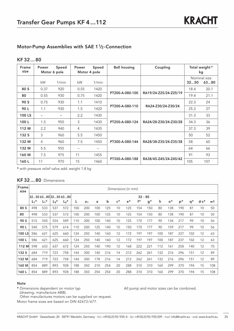
Motor-Pump Assemblies with SAE 11⁄2-Connection
KF 32 ... 80
with pressure relief valve
KF 32 ... 80 Pump sizes (in mm)
Nominalsize
F J J1
32...50 84 173 212
63 / 80 100 208 247
M 12 –20 deep
M 12 –20 deep
KRACHT GmbH · Gewerbestr. 20 · 58791 Werdohl, Germany · fon +49(0)23 92/935-0 · fax +49(0)23 92/935 209 · mail [email protected] · web www.kracht.eu 35
Transfer Gear Pumps KF 4...112
Motor-Pump Assemblies with SAE 11⁄2-Connection
KF 32 ... 80 Dimensions
Frame Dimensions (in mm)size
32...50 63...80 32...50 63...80 32 - 80L1* L1* L2* L2* L a1 a b c* e* f* g* h o* p* q* ø s* w1
80 S 498 533 537 572 100 200 100 125 10 125 154 150 80 138 190 87 10 50
80 498 533 537 572 100 200 100 125 10 125 154 150 80 138 190 87 10 50
90 S 515 550 554 589 110 200 100 140 10 125 170 177 90 134 217 99 10 56
90 L 540 575 579 614 110 200 125 140 10 150 170 177 90 159 217 99 10 56
100 LS 586 621 625 660 124 250 140 160 12 172 197 197 100 187 237 102 12 63
100 L 586 621 625 660 124 250 140 160 12 172 197 197 100 187 237 102 12 63
112 M 598 633 637 672 124 250 140 190 12 168 222 221 112 161 258 140 12 70
132 S 684 719 723 758 144 300 140 216 14 212 262 261 132 216 296 151 12 89
132 M 684 719 723 758 144 300 178 216 14 212 262 261 132 216 296 151 12 89
160 M 854 889 893 928 188 350 210 254 20 288 310 310 160 299 370 194 15 108
160 L 854 889 893 928 188 350 254 254 20 288 310 310 160 299 370 194 15 108
KF 32 ... 80
Frame Power Speed Power Speed Bell housing Coupling Total weight *size Motor 6 pole Motor 4 pole kg
Nominal sizekW 1/min kW 1/min 32...50 63...80
80 S 0.37 920 0.55 1420PT200-A-080-100 RA19/24-Z25/24-Z25/19
18.4 20.1
80 0.55 930 0.75 1420 19.4 21.1
90 S 0.75 930 1.1 1410PT200-A-080-110 RA24-Z30/24-Z30/24
22.3 24
90 L 1.1 930 1.5 1420 25.3 27
100 LS – – 2.2 1430 31.3 33
100 L 1.5 950 3 1430 PT250-A-080-124 RA24/28-Z30/24-Z30/28 34.3 36
112 M 2.2 940 4 1435 37.3 39
132 S 3 960 5.5 1450 50 52
132 M 4 960 7.5 1450 PT300-A-080-144 RA28/38-Z35/24-Z35/38 58 60
132 M 5.5 955 – – 64 66
160 M 7.5 975 11 1455PT350-A-080-188 RA38/45-Z45/24-Z45/42
91 93
160 L 11 970 15 1460 105 107
* with pressure relief valve add. weight 1.8 kg
Note* Dimensions dependent on motor typ
(drawing: manufacture ABB).Other manufactures motors can be supplied on request.
Motor frame sizes are based on DIN 42673/677.
All pump and motor sizes can be combined.

KRACHT GmbH · Gewerbestr. 20 · 58791 Werdohl, Germany · fon +49(0)23 92/935-0 · fax +49(0)23 92/935 209 · mail [email protected] · web www.kracht.eu36
Transfer Gear Pumps KF 4...112
Motor-Pump Assemblies with SAE 2-Connection
KF 100/112
KF 100/112 Pump sizes (in mm)
with pressure relief valve
Nominalsize
F J J1
100/112 102 220.5 262.5
M 12 –20 deep
M 12 –20 deep

KRACHT GmbH · Gewerbestr. 20 · 58791 Werdohl, Germany · fon +49(0)23 92/935-0 · fax +49(0)23 92/935 209 · mail [email protected] · web www.kracht.eu 37
Transfer Gear Pumps KF 4...112
Frame Power Speed Power Speed Bell housing Coupling Total weight *size Motor 6 pole Motor 4 pole kg
Motor MotorkW 1/min kW 1/min 6 pole 4 pole
100 LS – – 2.2 1430 – 72.2
100 L 1.5 940 3.0 1430 PT250-A-110-135 RA24/28-Z30/28-Z30/28 67.2 72.2
112 M 2.2 930 4.0 1425 72.2 74.2
132 S 3.0 955 5.5 1445 80.2 77.9
132 M 4.0 955 7.5 1445PT300-A-110-168 RA28/38-Z35/28-Z35/38
80.2 77.9
160 M 7.5 960 11.0 1445PT350-A-110-188 RA38/45-Z45/28-Z45/42
80.1 83.2
160 L 11.0 960 15.0 1455 80.1 83.2
180 M – – 18.5 1455PT350-A-110-204 RA42/55-Z50/28-Z50/48
– 84.9
180 L 15.0 970 22.0 1460 81.9 85.8
* with pressure relief valve add, weight 5.7 kg
Motor-Pump Assemblies with SAE 2-Connection
KF 100/112
KF 100/112 Dimensions
Frame Dimensions (in mm)size
100/112L1* L2* L a1 a b c* e* f* g* h o* p* q* ø s* w1
100 LS 644.5 686.5 135 250 140 160 12 172 197 197 100 187 237 102 12 63
100 L 644.5 686.5 135 250 140 160 12 172 197 197 100 187 237 102 12 63
112 M 656.5 698.5 135 250 140 190 12 168 222 221 112 161 258 140 12 70
132 S 755.5 797.5 168 300 140 216 14 212 262 261 132 216 296 151 12 89
132 M 755.5 797.5 168 300 178 216 14 212 262 261 132 216 296 151 12 89
160 M 901.5 943.5 188 350 210 254 20 288 310 310 160 299 370 194 15 108
160 L 901.5 943.5 188 350 254 254 20 288 310 310 160 299 370 194 15 108
180 M 917.5 959.5 204 350 279 279 20 316 340 310 180 299 390 194 15 121
180 L 958.5 1000.50 204 350 279 279 20 316 340 310 180 340 390 194 15 121
Note
* Dimensions dependent on motor typ(drawing: manufacture ABB).Other manufactures motors can be supplied on request.
Motor frame sizes are based on DIN 42673/677.
All pump and motor sizes can be combined.

KRACHT GmbH · Gewerbestr. 20 · 58791 Werdohl, Germany · fon +49(0)23 92/935-0 · fax +49(0)23 92/935 209 · mail [email protected] · web www.kracht.eu38
Transfer Gear Pumps KF 4...112
O-Ring 25,0 x 3,53 O-Ring 25,0 x 3,53
Accessory Connections
Threaded Flange G-SAE 3⁄4 Welding Flange S-SAE 3⁄4
N = NBR O-RingF = FKM O-RingP = PTFE O-Ring
Weight 0.39 kg – N– F– P
Weight 0.39 kg – N– F– P
O-Ring 32,92 x 3,53 O-Ring 32,92 x 3,53
Threaded Flange G-SAE 1 Welding Flange S-SAE 1
Weight 0.46 kg – N– F– P
Weight 0.46 kg – N– F– P

KRACHT GmbH · Gewerbestr. 20 · 58791 Werdohl, Germany · fon +49(0)23 92/935-0 · fax +49(0)23 92/935 209 · mail [email protected] · web www.kracht.eu 39
Transfer Gear Pumps KF 4...112
Accessory Connections
1825
G 1
1/2"
44
M12
ø38
24
35,7
69,9
94
77
1825
ø48,
6
44
M12
ø38
35,7
69,9
94
77
69,9
Threaded Flange G-SAE 11⁄2 Welding Flange S-SAE 11⁄2
N = NBR O-RingF = FKM O-RingP = PTFE O-Ring
Weight 1.05 kg – N– F– P
Weight 1.05 kg – N– F– P
Threaded Flange G-SAE 2
Weight 1.19 kg – N– F– P
O-Ring 56.74 x 3.53
Welding Flange S-SAE 2
Weight 1.19 kg – N– F– P
O-Ring 56.74 x 3.53
Cheesehead screwM12x45 DIN 912
O-Ring 47.22 x 3.52
Cheesehead screwM12x45 DIN 912
O-Ring 47.22 x 3.52

KRACHT GmbH · Gewerbestr. 20 · 58791 Werdohl, Germany · fon +49(0)23 92/935-0 · fax +49(0)23 92/935 209 · mail [email protected] · web www.kracht.eu40
Transfer Gear Pumps KF 4...112
Accessory Quench Chamber
Quench tank Adapter for screw size tap G 1⁄8
Accessory Connections
Threaded Flange G-SAE 2 1⁄2 Welding Flange S-SAE 2 1⁄2
N = NBR O-RingF = FKM O-RingP = PTFE O-Ring
Weight 1.4 kg – N– F– P
Weight 1.4 kg – N– F– P
O-Ring 69,44 x 3.53O-Ring 69,44 x 3.53

KRACHT GmbH · Gewerbestr. 20 · 58791 Werdohl, Germany · fon +49(0)23 92/935-0 · fax +49(0)23 92/935 209 · mail [email protected] · web www.kracht.eu 41
Transfer Gear Pumps KF 4...112
Note

KRACHT GmbH · Gewerbestr. 20 · 58791 Werdohl, Germany · fon +49(0)23 92/935-0 · fax +49(0)23 92/935 209 · mail [email protected] · web www.kracht.eu42
Note
Transfer Gear Pumps KF 4...112

KRACHT GmbH · Gewerbestr. 20 · 58791 Werdohl, Germany · fon +49(0)23 92/935-0 · fax +49(0)23 92/935 209 · mail [email protected] · web www.kracht.eu 43
Note
Transfer Gear Pumps KF 4...112

KF4...112/GB/08.10
KRACHT GmbH · Gewerbestraße 20 · 58791 Werdohl, Germany · fon +49 (0) 23 92 / 935-0 · fax +49 (0) 23 92 / 935 209
mail [email protected] · web www.kracht.eu
Transfer PumpsTransfer pumps for lubricating oil supply equipment, low pressure filling and feed systems, dosing and mixing systems.
Mobile HydraulicsSingle and multistage high pressure gear pumps, hydraulic motors and valves for construction machinery, vehicle-mounted machines.
Flow MeasurementGear and turbine flow meters and electronics for volume and flow metering technology in hydraulics, processing and laquering technology.
Industrial Hydraulics /Test Bench ConstructionCetop directional control and proportional valves, hydraulic cylinders, pressure, quantity and stop valves for pipe and slab construction, hydraulic accessories for industrial hydraulics (mobile and stationary use).
Technology Test benches / Fluid Test benches.
Product Portfolio