TRANSFER CASE - TOD - narod.rumersocar.narod.ru/files/5D2_1.pdf · electromagnetic clutch. ... •...
53
SECTION 5D2 TRANSFER CASE - TOD TABLE OF CONTENTS General Operation and Description ................... 5D2-2 TOD System Function ........................................ 5D2-2 4WD Operation Overview ................................... 5D2-3 System Structure ............................................... 5D2-4 4H Mode (4WD Drive - High Speed) ................... 5D2-5 4L Mode (4WD Drive - Low Speed) ..................... 5D2-7 Specifications .................................................... 5D2-9 Tightening Specifications ................................. 5D2-10 Component Locator ......................................... 5D2-11 Transfer Case Cross Sectional View ................. 5D2-11 Transfer Case Assembly .................................. 5D2-13 Function Description ........................................ 5D2-14 TOD System Select Mode ................................ 5D2-14 Component Function ........................................ 5D2-14 Definition fo Terminology .................................. 5D2-16 Control Unit ..................................................... 5D2-18 System Operation ............................................ 5D2-20 Diagnosis .......................................................... 5D2-30 Diagnostic Tests .............................................. 5D2-24 Coding on TOD ................................................ 5D2-25 Schmatic Wiring Diagram ................................. 5D2-27 TOD Control Unit Diagnostic System Check ..... 5D2-28 Diagnostic Trouble Codes (DTC’s) ................... 5D2-29 4WD Check Indicator Stays on with Ignition Switch on ...................................................... 5D2-30 4WD Low Indicator Stays on with Ignition Switch on ...................................................... 5D2-31 No 4WD Check or 4WD Low Indicator with Ignition Switch on ......................................... 5D2-32 4WD Low Indicator Blink Steadily ..................... 5D2-33 Diagnostic Trouble Code (DTC) 1714 ................ 5D2-34 Diagnostic Trouble Code (DTC) 1715 ................ 5D2-36 Diagnostic Trouble Code (DTC) 1716 ................ 5D2-38 Diagnostic Trouble Code (DTC) 1721 ................ 5D2-40 Diagnostic Trouble Code (DTC) 1722 ................ 5D2-42 Diagnostic Trouble Code (DTC) 1731 ................ 5D2-44 Diagnostic Trouble Code (DTC) 1732 ................ 5D2-46 Diagnostic Trouble Code (DTC) 1733 ................ 5D2-48 Diagnostic Trouble Code (DTC) 1734 ................ 5D2-50 Diagnostic Trouble Code (DTC) 1735 ................ 5D2-52 Diagnostic Trouble Code (DTC) 1736 ................ 5D2-54 Diagnostic Trouble Code (DTC) 1741 ................ 5D2-56 Diagnostic Trouble Code (DTC) 1742 ................ 5D2-58 Diagnostic Trouble Code (DTC) 1743 ................ 5D2-60 Diagnostic Trouble Code (DTC) 1750 ................ 5D2-61 Diagnostic Trouble Code (DTC) 1751 ................ 5D2-63 Diagnostic Trouble Code (DTC) 1752 ................ 5D2-64 Diagnostic Trouble Code (DTC) 1753 ................ 5D2-65 Diagnostic Trouble Code (DTC) 1754 ................ 5D2-66 Maintenance and Repair ................................. 5D2-67 On-Vehicle Service ............................................. 5D2-67 Transfer Case (TOD) Component Locator ......... 5D2-67 Transfer Case Assembly .................................. 5D2-68 TOD Control Unit .............................................. 5D2-70 Shift Motor ....................................................... 5D2-70 Speed Sensor in Front and Rear Propeller Shaft 5D2-71 Unit Repair ........................................................ 5D2-74 Transfer Case Assembly .................................. 5D2-76 Special Tools and Equipment .......................... 5D2-89 Special Tools Table ......................................... 5D2-89
Transcript of TRANSFER CASE - TOD - narod.rumersocar.narod.ru/files/5D2_1.pdf · electromagnetic clutch. ... •...

SECTION 5D2
TRANSFER CASE - TOD
TABLE OF CONTENTS
General Operation and Description................... 5D2-2
TOD System Function ........................................ 5D2-2
4WD Operation Overview ................................... 5D2-3
System Structure ............................................... 5D2-4
4H Mode (4WD Drive - High Speed) ................... 5D2-5
4L Mode (4WD Drive - Low Speed) ..................... 5D2-7
Specifications .................................................... 5D2-9
Tightening Specifications ................................. 5D2-10
Component Locator ......................................... 5D2-11
Transfer Case Cross Sectional View ................. 5D2-11
Transfer Case Assembly .................................. 5D2-13
Function Description ........................................ 5D2-14
TOD System Select Mode ................................ 5D2-14
Component Function ........................................ 5D2-14
Definition fo Terminology .................................. 5D2-16
Control Unit ..................................................... 5D2-18
System Operation ............................................ 5D2-20
Diagnosis .......................................................... 5D2-30
Diagnostic Tests .............................................. 5D2-24
Coding on TOD ................................................ 5D2-25
Schmatic Wiring Diagram ................................. 5D2-27
TOD Control Unit Diagnostic System Check ..... 5D2-28
Diagnostic Trouble Codes (DTC’s) ................... 5D2-29
4WD Check Indicator Stays on with IgnitionSwitch on ...................................................... 5D2-30
4WD Low Indicator Stays on with IgnitionSwitch on ...................................................... 5D2-31
No 4WD Check or 4WD Low Indicator withIgnition Switch on ......................................... 5D2-32
4WD Low Indicator Blink Steadily ..................... 5D2-33
Diagnostic Trouble Code (DTC) 1714 ................ 5D2-34
Diagnostic Trouble Code (DTC) 1715 ................ 5D2-36
Diagnostic Trouble Code (DTC) 1716 ................ 5D2-38
Diagnostic Trouble Code (DTC) 1721 ................ 5D2-40
Diagnostic Trouble Code (DTC) 1722 ................ 5D2-42
Diagnostic Trouble Code (DTC) 1731 ................ 5D2-44
Diagnostic Trouble Code (DTC) 1732 ................ 5D2-46
Diagnostic Trouble Code (DTC) 1733 ................ 5D2-48
Diagnostic Trouble Code (DTC) 1734 ................ 5D2-50
Diagnostic Trouble Code (DTC) 1735 ................ 5D2-52
Diagnostic Trouble Code (DTC) 1736 ................ 5D2-54
Diagnostic Trouble Code (DTC) 1741 ................ 5D2-56
Diagnostic Trouble Code (DTC) 1742 ................ 5D2-58
Diagnostic Trouble Code (DTC) 1743 ................ 5D2-60
Diagnostic Trouble Code (DTC) 1750 ................ 5D2-61
Diagnostic Trouble Code (DTC) 1751 ................ 5D2-63
Diagnostic Trouble Code (DTC) 1752 ................ 5D2-64
Diagnostic Trouble Code (DTC) 1753 ................ 5D2-65
Diagnostic Trouble Code (DTC) 1754 ................ 5D2-66
Maintenance and Repair ................................. 5D2-67
On-Vehicle Service ............................................. 5D2-67
Transfer Case (TOD) Component Locator ......... 5D2-67
Transfer Case Assembly .................................. 5D2-68
TOD Control Unit .............................................. 5D2-70
Shift Motor ....................................................... 5D2-70
Speed Sensor in Front and Rear Propeller Shaft 5D2-71
Unit Repair ........................................................ 5D2-74
Transfer Case Assembly .................................. 5D2-76
Special Tools and Equipment .......................... 5D2-89
Special Tools Table ......................................... 5D2-89

SSANGYONG Y200
5D2-2 TRANSFER CASE - TOD
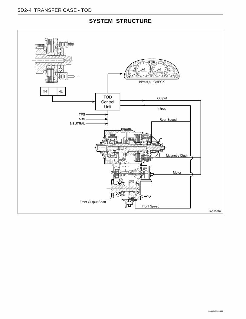
GENERAL INFORMATION AND OPERATIONTOD system means the full time 4WD system and theregistered trade mark of Borg Warner. TOD is anabbreviation of Torque On Demand.
TOD control unit automatically tailors torque distributionto road, offering full time four wheel drive. TODdistributes electronically-controlled power into front andrear wheels whose ratio change from 0 : 100 to 50 : 50complying with wheel speed differences.
Also TOD control unit analyzes data from wheel speedsensor and engine output then changes pressure ofelectromagnetic clutch. This pressure controls frontpropeller shaft and power to front wheel. Power to frontwheel depends on degree of pressure correspondingclutch slip.
TOD is designed to distribute the power to front andrear axle by operation of 4H/4L switch and shift motor.Shifting 4WD high (4H) to 4WD low (4L) is performedtowards reducing high-low collar by means forconnection high-low shift fork with output shaft in orderto join with planetary gear. Torque transmits input shaftthen sun gear rotating front planetary gear. Frontplanetary gear joins with output shaft and drives atlow position.
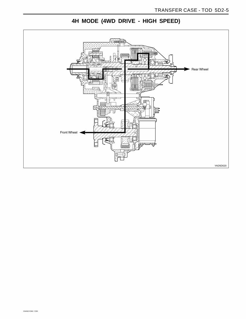
The TOD system has 2 selectable mode, 4H and 4L.4H is the normal operating mode when drive of whichgear ratio is 1:1 and 4L mode distributes power tofront and rear wheels 50 : 50 of which gear ratio is2.48:1.
TOD SYSTEM FUNCTION4H ModeThe TOD system transfer case controls the clutchmechanism to comply with rotation in front and rearpropeller shaft and if its difference exceeds thepermissible range, corresponding power is distributedinto front wheel through electromagnetic clutch (EMC).
Hall effect speed sensors are located front and rearpropeller shafts, send signals to TOD transfer casecontrol unit (TCCU). The EMC coil is activated byvariable current on exceeding difference of speed infront and rear propeller shafts.
4L ModeWhen select 4L mode, EMC is locked to applymaximum torque into front and rear propeller shafts.Shift motor rotates also 4L position by rotation of camthus propeller shaft torque changes from 1:1 to 2.48:1by planetary gear set.
Transfer Case Control Unit (TCCU)Transfer case control unit (TCCU) receives, front andrear propeller shaft speed, shift motor position and4H/4L switch signals and controls electromagneticclutch (EMC), shift motor. TCCU communicates withscan tool with K-line for diagnosis. It located underthe front LH seat.

TRANSFER CASE - TOD 5D2-3
SSANGYONG Y200
4WD Drive(High
Speed)
4WD Drive(Low
Speed)
4WD Drive
High Speed ↔Low Speed
4WD OPERATION OVERVIEW
Driving Type
Transferring
4H
4L
4H ↔ 4L
ApplicationNormal Driving on the normal road or highway, or high
speed driving
Slipped road such as snow, rainy, sand, mud etc.
Max driving force requiring condition such as towing,
rough road.
Same function as part time transfer case 4L.
A vehicle should stop for transfer.
Manual Transmission
• Transfer starts after the vehicle stops and the clutch
is applied
Automatic Transmission
• Transfer starts after the vehicle stops and the shift
lever is shifted [N] position.
Operation ConditionMode Position
Notice: After the vehicle stops and the mode switchis selected with applying the brake pedal, shifting [N-R-N] makes the mode transfer easier.
SSANGYONG Y200
5D2-4 TRANSFER CASE - TOD
yyyyyyyyyyyy
@@@@ÀÀÀÀ
yyyyyy
Q¢Q¢Q¢Q¢Q¢Q¢Q¢Q¢Q¢
@@@@ÀÀÀÀ@@@@ÀÀÀÀ@@ÀÀ
yy@@ÀÀ
yyyy@@@@ÀÀÀÀ
yyQ¢Q¢Q¢Q¢Q¢QQ¢¢Q¢Q¢Q¢yyy
QQQQ¢¢¢¢
QQQQQQ¢¢¢¢¢¢
yyyyQQ¢¢QQ¢¢
@@ÀÀ
y
@À
y@À
@@@@ÀÀÀÀyyyQ¢
QQQQQQ¢¢¢¢¢¢
@@ÀÀyyyQQ¢¢
Q¢QQ¢¢
yQ¢
yyyyyyyyy
y
@@@@@@ÀÀÀÀÀÀ
yyyyyyQ¢Q¢yyyy
Q¢QQQQ¢¢¢¢
QQQQ¢¢¢¢
QQQQ¢¢¢¢@@ÀÀ
Q¢Q¢
@@@@ÀÀÀÀ
@@@@ÀÀÀÀ@@@ÀÀÀ@À
yy@@ÀÀ
yyyyyy
@@@@@@@@@
ÀÀÀÀÀÀÀÀÀ
yyQ¢Q¢Q¢Q¢Q¢Q¢Q¢Q¢Q¢
@@@ÀÀÀyyyy@@ÀÀ
@@@@@@@@@
ÀÀÀÀÀÀÀÀÀ
yy
yyyyyy
SYSTEM STRUCTURE
YAD5D010
TRANSFER CASE - TOD 5D2-5
SSANGYONG Y200
yyyyyyyyyyyyyyyyyyyy
@@@@@@ÀÀÀÀÀÀ
yyyyyyyyyyyyyyy
Q¢Q¢Q¢Q¢Q¢Q¢Q¢Q¢Q¢
@@@@@@ÀÀÀÀÀÀ@@@@@@ÀÀÀÀÀÀ@@@@ÀÀÀÀ
yyyy@@@@ÀÀÀÀ
yyyyyy
@@@@@@@@@@@@
ÀÀÀÀÀÀÀÀÀÀÀÀ
yQ¢Q¢Q¢Q¢Q¢Q¢Q¢Q¢Q¢yy
yyyyQQ¢¢
QQQQQQQQQQQQ
¢¢¢¢¢¢¢¢¢¢¢¢
yyyyyyyyyQQ¢¢QQQQ¢¢¢¢
@@@@@@ÀÀÀÀÀÀ
yy@@ÀÀ
yy@@@@ÀÀÀÀ
@@@@@@@@@
ÀÀÀÀÀÀÀÀÀ
yyyyyyyQQ¢¢
QQQQQQQQ¢¢¢¢¢¢¢¢@@ÀÀ
yyyyyyyyQQ¢¢
QQ¢¢
Q¢yyyyQQ¢¢
yyyyyyyyyyyyyyyyyyyy
y
@@@@@@@@@@@@
ÀÀÀÀÀÀÀÀÀÀÀÀ
yyyyyyyyyyQQ¢¢QQ¢¢
yyyy
QQ¢¢
QQ¢¢
Q¢
QQQQQ¢¢¢¢¢@@ÀÀ
QQ¢¢Q¢
4H MODE (4WD DRIVE - HIGH SPEED)
YAD5D020
SSANGYONG Y200
5D2-6 TRANSFER CASE - TOD
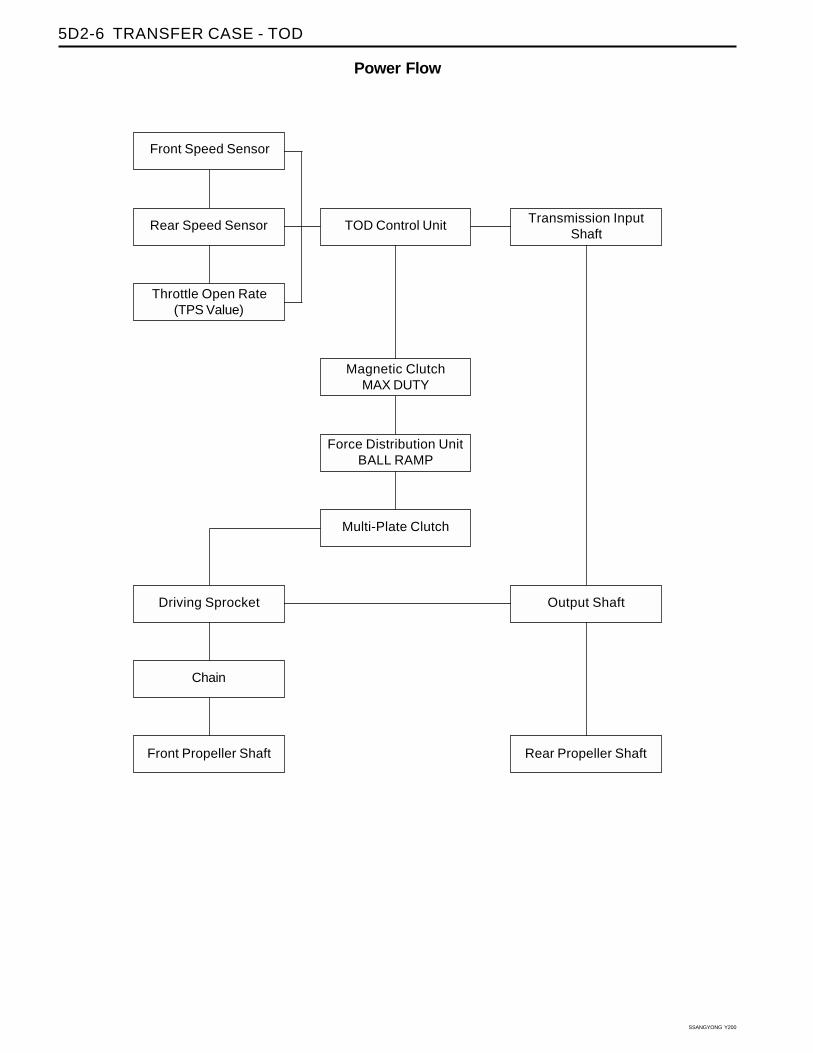
Power Flow
Output Shaft
Rear Propeller Shaft
Rear Speed Sensor TOD Control Unit
Magnetic ClutchMAX DUTY
Multi-Plate Clutch
Front Propeller Shaft
Throttle Open Rate(TPS Value)
Driving Sprocket
Force Distribution UnitBALL RAMP
Transmission InputShaft
Front Speed Sensor
Chain

TRANSFER CASE - TOD 5D2-7
SSANGYONG Y200
yyyyyyyyyyyyyyyyyyyy
@@@@@@ÀÀÀÀÀÀ
yyyyyyyyyyyyyyy
Q¢Q¢Q¢Q¢Q¢Q¢Q¢Q¢Q¢
@@@@@@ÀÀÀÀÀÀ@@@@@@ÀÀÀÀÀÀ@@@@ÀÀÀÀ
yyyy@@@@ÀÀÀÀ
yyyyyy
@@@@@@@@@@@@
ÀÀÀÀÀÀÀÀÀÀÀÀ
yQ¢Q¢Q¢Q¢Q¢Q¢Q¢Q¢Q¢yyyyyyQQ¢¢
QQQQQQQQQQQQ
¢¢¢¢¢¢¢¢¢¢¢¢
yyyyyyyyyQQ¢¢QQQQ¢¢¢¢
@@@@@@ÀÀÀÀÀÀ
yy@@ÀÀ
yy@@@@ÀÀÀÀ
@@@@@@@@@
ÀÀÀÀÀÀÀÀÀ
yyyyyyyQQ¢¢
QQQQQQQQ¢¢¢¢¢¢¢¢@@ÀÀ
yyyyyyyyQQ¢¢
QQ¢¢
Q¢yyyyQQ¢¢
yyyyyyyyyyyyyyyyyyyy
y
@@@@@@@@@@@@
ÀÀÀÀÀÀÀÀÀÀÀÀ
yyyyyyyyyyQQ¢¢QQ¢¢
yyyy
QQ¢¢
QQ¢¢
Q¢
QQQQQ¢¢¢¢¢@@ÀÀ
QQ¢¢Q¢
4L MODE (4WD DRIVE - LOW SPEED)
YAD5D030

SSANGYONG Y200
5D2-8 TRANSFER CASE - TOD
Power Flow
Output Shaft
Rear Propeller Shaft
Rear Speed Sensor TOD Control Unit
Magnetic ClutchMAX DUTY
Multi-Plate Clutch
Front Propeller Shaft
Front Speed Sensor
Throttle Open Rate(TPS Value)
Driving Sprocket
Force Distribution UnitBALL RAMP
Transmission InputShaft
Planetary Gear(2.483)
Chain

TRANSFER CASE - TOD 5D2-9
SSANGYONG Y200
Normal Range
CAN Comm.
Ignition Switch OFF
Ignition Switch ON
Motor OFF
Motor ON
TOD (Torque On Demand) Transfer Case (4423E)
343.0 mm
37.9 kg
4H and 4L
1 : 1
2.48 : 1
ATF S-3, S-4 or Dexron II, III
1.4 L
Inspect Every 15,000km,
Replace Every 50,000km
550 lb ft (76kg cm)
9-16 V
6-16 V
2 mA
1 A
7 A
20 A
High
Low
Specification
Capacity
Interval
TOD
TOD Control
Unit
Model
Length
Weight (w/oil)
Shift Mode
Gear Ratio
Oil
Max. Torque
Voltage
Current(Below Max.
Operation Voltage)
Max. Operation Current
SPECIFICATIONS
Check Action

SSANGYONG Y200
5D2-10 TRANSFER CASE - TOD
TIGHTENING SPECIFICATIONS
Application
Clutch Coil Retaining Bolt
Drain Plug
Filter Plug
Front Case - Rear Case Mounting Bolt
Front Propeller Shaft - Front Output Shaft/Flange Mounting Bolt
Planner Damper - Transfer Case Mounting Bolt
Rear Output Shaft Flange Mounting Nut
Rear Propeller Shaft - Rear Output Shaft/Flange Mounting Bolt
Shift Motor Adjusting Nut
Shift Motor Bracket Bolt
Shift Motor Mounting Bolt
Speed Sensor Retaining Bolt
Transfer Case Control Unit (TCCU) Retaining Bolts
Transfer Case - Transmission Adapter Housing Mounting Bolt
N•m
10
25
25
31
85
35
167
85
5
10
10
5
10
48
Kgf.m
1.0
2.5
2.5
3.1
8.6
3.6
17.0
8.7
0.5
1.0
1.0
0.5
1.0
4.9

TRANSFER CASE - TOD 5D2-11
SSANGYONG Y200
yyyyyyyyyyyyyyyyyyyyyyyyyyyyyyyyyyyyyyyyyy
@@@@@@
ÀÀÀÀÀÀ
yyyyyyyyyyyyyyyyyyyyy
Q¢Q¢Q¢Q¢Q¢Q¢Q¢Q¢Q¢
@@@@@@
ÀÀÀÀÀÀ
@@@@@@
ÀÀÀÀÀÀ@@ÀÀ
yyyyyy@@@ÀÀÀ
yyyyyyyyyyyy
@@@@@@@@@@@@@@@@
ÀÀÀÀÀÀÀÀÀÀÀÀÀÀÀÀyy
QQ¢¢QQ¢¢QQ¢¢QQ¢¢QQ¢¢QQ¢¢QQ¢¢QQ¢¢QQ¢¢yyyy
QQQQQQ
¢¢¢¢¢¢
QQQQQQQQQQQQQQQQQQQQ
¢¢¢¢¢¢¢¢¢¢¢¢¢¢¢¢¢¢¢¢
yy
yyyyyyyyyyQQ¢¢
QQQQ¢¢¢¢
@@@@@@
ÀÀÀÀÀÀ
y
@@ÀÀ
yyyy@@@ÀÀÀ
@@@@@@@@@@@@@@@@
ÀÀÀÀÀÀÀÀÀÀÀÀÀÀÀÀyy
yyyyyyyyyyyy
QQQ
¢¢¢
QQQQQQQQQQQQQQQ
¢¢¢¢¢¢¢¢¢¢¢¢¢¢¢
@@@@ÀÀÀÀ
yyyyyyyyyy
QQQQ¢¢¢¢
Q¢QQ¢¢
yyyyQQ¢¢
yyyyyyyyyyyyyyyyyyyyyyyyyyyyyyyyyyy
yyyy
@@@@@@@@@@@@
ÀÀÀÀÀÀÀÀÀÀÀÀ
yyyyyyyyyyyyyQQ¢¢Q¢
yyyy
QQQ¢¢¢
QQQQ¢¢¢¢
QQ¢¢
QQQQQQQ
¢¢¢¢¢¢¢
@@@
ÀÀÀ
QQQQ¢¢¢¢
QQQQ¢¢¢¢
COMPONENT LOCATORTRANSFER CASE CROSS SECTIONAL VIEW
YAD5D040

SSANGYONG Y200
5D2-12 TRANSFER CASE - TOD
1 Case2 Bearing3 Ring Gear4 Oil Seal5 Retaining Ring6 Input Shaft7 Carrier8 Pinion Gear9 Pinion Shaft
10 Thrust Washer11 Needle Roller12 Spacer13 Bearing14 Bushing15 Sun Gear16 Thrust Plate17 Hub18 Bearing19 Snap Ring20 Snap Ring21 Snap Ring22 Hub Reduction23 Shift Fork24 Spacer25 Shaft Shift26 Spring27 Cam28 Breather Hose29 Breather Plug30 Shift Rail31 Intermediate Shaft32 Thrust Washer33 Pump34 Clamp Hose35 Upper Sprocket36 Thrust Washer
37 Chain38 Cover39 Bearing40 Oil Seal41 Dowel Pin42 Bearing Sleeve43 Seal44 Snap Ring45 Center Bearing Support46 Ball Bearing47 Dowel Pin48 Viscous Coupling49 Pinion Gear50 Thrust Washer51 Pinion Shaft52 Thrust Washer53 Thrust Washer54 Bushing55 Output Shaft56 Ring Gear57 Retaining Ring58 Needle Bearing59 Ball Bearing60 Speed Gear61 Flange62 Oil Seal63 Washer64 Nut65 Flange66 Dust Deflector67 Tone Wheel68 Bolt69 Motor70 Bolt71 Cap Screw

TRANSFER CASE - TOD 5D2-13
SSANGYONG Y200
TRANSFER CASE ASSEMBLY
YAD5D050
1 Input Shaft2 Air Control Cap3 Front Companion Flange4 Rear Companion Flange
5 Drain Plug6 Filler Plug7 Shift Cam Driving Motor

SSANGYONG Y200
5D2-14 TRANSFER CASE - TOD
FUNCTION DESCRIPTION
TOD system controls clutch mechanism to comply withrotation in front and rear propeller shaft and if itsdif ference exceeds the permissible range,corresponding power is distributed into front wheelthrough EMC (Electro-Magnetic Clutch). Hall effectsensor signals speed on front and rear propeller shaftsgoing through with TOD control unit.
Transfer case clutch coil is activated by variable currenton exceeding difference of speed in front and rearpropeller shafts.
Select 4L ModeWhen select 4L mode, EMC is locked to applymaximum torque into front and rear propeller shafts.Shift motor rotates also 4L position by rotation of camthus propeller shaft torque changes from 1 : 1 to 2.48 : 1by planetary gear set.
Deselect 4L ModeWhen select 4H mode, the 4WD mode is deselectedand returns the 4WD - high speed mode.
• “4H” switch : Slef-return Type
• “4L” switch : Push Lock Type
YAD5D060
TOD SYSTEM SELECT MODE4H is the mode when drive normally of which gear ratiois 1 : 1 and 4L mode distributes power to front andrear wheels 50 : 50 of which gear ratio is 2.48 : 1.
COMPONENT FUNCTIONShift MotorIt locates backside transfer case, which drives rotaryhelical cam. When mode select switch changes to 4L,shift fork is on position for 2.48:1 by rotation of helicalcam.
Transfer CaseTOD transfer case distributes power into front and rearaxle by operation of 4H/4L switch and shift motor.Shifting 4H to 4L, is performed towards reducing HI-LO collar by means for connection HI-LO shift fork withoutput shaft in order to join with planetary gear. Torquetransmits input shaft then sun gear rotating frontplanetary gear. Front planetary gear join with outputshaft and drives LO position.
TOD Control UnitTOD control unit is located on the floor under the driverseat.
YAD5D070
Shape and function of TOD Control Unit
YAD5D080

TRANSFER CASE - TOD 5D2-15
SSANGYONG Y200
Speed Sensor, Clutch Coil, Motor Connector
Speed Sensor, Clutch Coil and Motor Connector arelocated at the upper & rear side of the transfer case(upper shift motor) as shown.
• Shift Motor Connector : Black (upper arrow asshown)
• Speed Sensor and Clutch Coil Connector : White(lower arrow as shown)
Shift Motor Connector
YAD5D090
YAD5D100
Speed sensor, clutch coil connector
YAD5D110
Function
Clutch Coil
Front Speed Return
Front Speed
Front Speed Sensor Voltage Supply
Rear Speed Sensor Voltage Supply
Rear Speed
Rear Speed Return
Pin
H
I
J
K
L
M
N
Pin
A
B
C
D
E
F
G
Function
Motor HI-LO (clockwise)
Motor HI-LO (counter-clockwise)
Position Return
Position 1
Position 2
Position 3
Position 4
Pin
1
2
3
4
5
6
7
8
9
10
11
12
13
14
15
Function
Motor HI-LO
Motor LO-HI
EMC
Battery (+)
Ignition
Position Return
Diagnosis Display
-
HI / LO Switch
Position 2
Front Speed
TPS Supply (Diesel)
Speed/TPS Return
Motor HI-LO
Motor LO-HI
Pin
16
17
18
19
20
21
22
23
24
25
26
27
28
29
30
Function
Speed Reference
Ground
Ground
Battery (+)
K-LINE
4L Illumination
CAN-H
CAN-L
Auto T/M, Neutral
ABS Input
Brake Switch
Position 1
Position 3
Rear Speed
Position 4

SSANGYONG Y200
5D2-16 TRANSFER CASE - TOD
DEFINITION OF TERMINOLOGY
Definitions
Rear Speed Sensor
Description
A Hall Effect speed sensor which produces a square wave. 0-5Vdc signal in response
to a rotating 30 tooth wheel coupled to the rear propeller shaft inside the Transfer
Case.
Each rotation of the rear propeller shaft will result in 30 speed sensor pulse.
A Hall Effect speed sensor which produces a square wave. 0-5Vdc signal in response
to a rotating 30 tooth wheel coupled to the front propeller shaft inside the Transfer
Case.
Each rotation of the front propeller shaft will result in 30 speed sensor pulse.
An Electromagnetic clutch used to control the amount of torque applied to the front
propeller shaft.
TOD is an abbreviation of Torque On Demand and means that the torque is transferred
according to the operating condition.
TPS is an abbreviation of Throttle Position Sensor. For MSE engine, the potentiometer
in the throttle actuator acts as TPS.
PWM is an abbreviation of Pulse Width Modulation and is a type of output value
control by adjusting pulse width.
Duty Cycle is the time the EMC is on divided by the period in which it is being modu-
lated.
A minimum amount of duty cycle applied to the EMC.
A condition where the front propeller shaft is turning at a rate which is faster than the
rear propeller shaft.
A condition where the rear propeller shaft is turning at a rate which is faster than the
front propeller shaft.
The highest (numerically lowest = 1 : 1) gear ratio between the input and outputs of
the Transfer Case.
The lowest (numerically highest = 2.48 : 1) gear ratio between the input and outputs of
the Transfer Case.
Front Speed Sensor
EMC (Electromagnetic
Clutch)
TOD
TPS (Throttle Position
Sensor)
PWM
Duty Cycle
Touch-off
Front Overrun
Rear Overrun
High Range
Low Range
YAD5D120

TRANSFER CASE - TOD 5D2-17
SSANGYONG Y200
Definitions
4H/4L Switch
Shift Motor
Position Encoder
Neutral Safety Switch
Shift Inhibit Speed
Description
A switch which selects the desired gear ratio.
Electric motor which changes the Transfer Case range.
A set of 4 Gray code switches which provide feedback to the TOD indicating the
position of the Shift Motor.
A switch on vehicles equipped with a manual transmission which indicates that the
clutch pedal is depressed.
A switch on vehicles equipped with an automatic transmission which indicates that the
transmission is in neutral.
The vehicle speed above which Transfer Case shifts are disallowed. Vehicle speed is
indicated by propeller shaft speed measurement.

SSANGYONG Y200
5D2-18 TRANSFER CASE - TOD
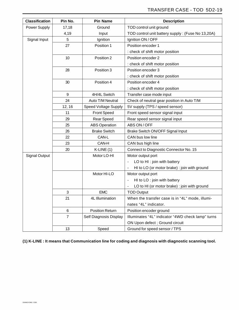
CONTROL UNITInput/Output diagramTOD control unit and main wiring harness is linked by30 pin connector. Each pin joins with switch andactuator whose details refer to the below diagram.
YAD5D130
TRANSFER CASE - TOD 5D2-19
SSANGYONG Y200
Description
TOD control unit ground
TOD control unit battery supply : (Fuse No 13,20A)
Ignition ON / OFF
Position encoder 1
: check of shift motor position
Position encoder 2
: check of shift motor position
Position encoder 3
: check of shift motor position
Position encoder 4
: check of shift motor position
Transfer case mode input
Check of neutral gear position in Auto T/M
5V supply (TPS / speed sensor)
Front speed sensor signal input
Rear speed sensor signal input
ABS ON / OFF
Brake Switch ON/OFF Signal Input
CAN bus low line
CAN bus high line
Connect to Diagnostic Connector No. 15
Motor output port
- LO to HI : join with battery
- HI to LO (or motor brake) : join with ground
Motor output port
- HI to LO : join with battery
- LO to HI (or motor brake) : join with ground
TOD Output
When the transfer case is in “4L” mode, illumi-
nates “4L” indicator.
Position encoder ground
Illuminates “4L” indicator “4WD check lamp” turns
ON Upon defect ; Ground circuit
Ground for speed sensor / TPS
Pin No.
17,18
4,19
5
27
10
28
30
9
24
12, 16
11
29
25
26
22
23
20
3
21
6
7
13
Pin Name
Ground
Input
Ignition
Position 1
Position 2
Position 3
Position 4
4H/4L Switch
Auto T/M Neutral
Speed Voltage Supply
Front Speed
Rear Speed
ABS Operation
Brake Switch
CAN-L
CAN-H
K-LINE (1)
Motor LO-HI
Motor HI-LO
EMC
4L Illumination
Position Return
Self Diagnosis Display
Speed
Classification
Power Supply
Signal Input
Signal Output
(1) K-LINE : It means that Communication line for coding and diagnosis with diagnostic scanning tool.
SSANGYONG Y200
5D2-20 TRANSFER CASE - TOD
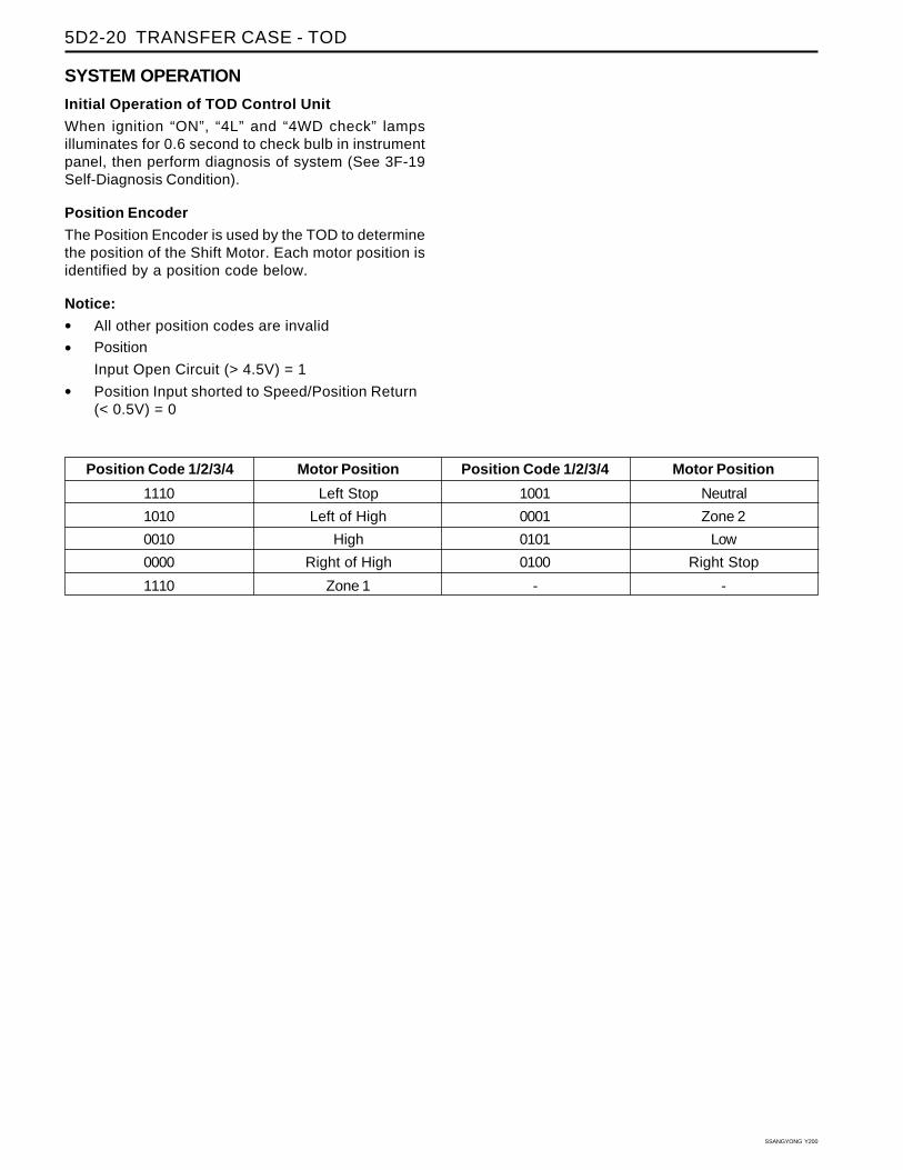
SYSTEM OPERATION
Initial Operation of TOD Control Unit
When ignition “ON”, “4L” and “4WD check” lampsilluminates for 0.6 second to check bulb in instrumentpanel, then perform diagnosis of system (See 3F-19Self-Diagnosis Condition).
Position Encoder
The Position Encoder is used by the TOD to determinethe position of the Shift Motor. Each motor position isidentified by a position code below.
Notice:
• All other position codes are invalid
• Position
Input Open Circuit (> 4.5V) = 1
• Position Input shorted to Speed/Position Return(< 0.5V) = 0
Position Code 1/2/3/4
1110
1010
0010
0000
1110
Motor Position
Left Stop
Left of High
High
Right of High
Zone 1
Position Code 1/2/3/4
1001
0001
0101
0100
-
Motor Position
Neutral
Zone 2
Low
Right Stop
-

TRANSFER CASE - TOD 5D2-21
SSANGYONG Y200
System Response (Action)
No action required. 4L bulb off.
No action required. 4L bulb off.
No action required. 4L bulb off.
Blink 4L bulb. After the shift conditions are met,
attempt a shift to 4H under conditions of below 87 rpm
in front and rear propeller shaft and “Neutral” position.
After successfully shifting into 4H, stop blinking 4L
bulb.
Same as above
Same as above
Same as above
Blink 4L bulb. After the shift conditions are met,
attempt a shift to 4L. After successfully shifting into
4L, stop blinking 4L bulb.
Same as above
Blink 4L bulb. After the shift conditions are met,
attempt a shift to 4L. After successfully shifting into
4L, stop blinking 4L bulb.
Same as above
Same as above
Same as above
Same as above
Same as above
Same as above
No action required. 4L bulb on.
No action required. 4L bulb on.
Motor Position
Left Stop
Left of High
High
Right of High
Zone 1
Neutral
Zone 2
Low
Right Stop
Left Stop
Left of High
High
Right of High
Zone 1
Neutral
Zone 2
Low
Right Stop
Position Sensor InterpretationWhen the module powers up, it will read the positionsensor and the 4H/4L switch input and respond to thepossible codes as follows.
4H/4L Switch Input
4H
4H
4H
4H
4H
4H
4H
4H
4H
4L
4L
4L
4L
4L
4L
4L
4L
4L

SSANGYONG Y200
5D2-22 TRANSFER CASE - TOD
A command to shift will only be acted upon if the TODis reading a valid code at the time the command toshift is made.
After a shift has started, the TOD will power the shiftmotor until the code for the requested position is read.If an invalid code is read, the TOD will go into a defaultmode.
During a shift attempt, the shift motor will be energizedfor a maximum of 5 seconds.
Electric Shift System OperationThe Electric Shift System is responsible for changingthe Transfer Case gear ratio by controlling the electricshift motor. The TOD monitors the 4H/4L switch, neutralswitch, speed sensors, position encoder, and ignitionswitch.
A range change is initiated when ;
1. The 4H/4L Switch is changed from 4H to 4L orfrom 4L to 4H.
2. The motor position (as indicated by the positionencoder) does not match the 4H/4L Switchimmediately after the ignition is turned on.
Shift criteriaWhen a range change is initiated a Diagnostic Testwill be completed on the motor, speed sensors, andposition encoder. If the Diagnostic Test fails, the shiftwill not be attempted. If all components are operatingproperly, the TOD will attempt a range change afterthe following shift criteria are met:
1. The transmission is in neutral for 2 seconds afterthe shift is requested.
2. Both propeller shaft speeds are below 87 rpm(2580 pulses/minute).
If the transmission is taken out of neutral before 2seconds has elapsed, or either propeller shaft speedincreases above the limit, the shift will be suspendedand the 4L Indicator will continue to blink until thecriteria are met again or the 4H/4L Switch is returnedto the original position.
Range changeWhen the shift criteria are met, the motor is rotated inthe appropriate direction (as determined by the selectorswitch) until one of the following occurs:
1. The motor reaches its destination.
2. The motor is on for 5 seconds without reaching itsdestination. The shift has failed and the TOD willrespond as default mode.
3. A fault occurs with either the motor or positionencoder. Refer to the diagnosis requirement.
When the motor is energized, the Ignition, 4H/4LSwitch, propeller shaft speeds, and transmissionneutral inputs are ignored.
Indicator function on shiftingOnce a range change has been initiated the 4L Indicatorwill begin to blink at a rate of 0.3 seconds on, 0.3seconds off until the shift is completed or canceled.
If a successful shift has been completed, the 4LIndicator will be illuminated if the motor is in Low andit will be turned off if the motor is in High.
4L Indicator illuminates as below figure.
Electric shift default mode
If the motor fails to reach its destination, the TOD willattempt the following (in order):
1. The TOD will wait 3 seconds then attempt the shiftagain.
2. If the second attempt to reach the destination failsthe TOD will wait 3 seconds then attempt to rotatethe motor back to the original posit ion. I fsuccessful, all future shifts will be inhibited untilthe Ignition is cycled.
3. If the attempt to return to the original position fails,the TOD will wait 3 seconds then attempt to rotatethe motor to the original position again. If thesecond attempt to return to the original position issuccessful, the 4WD CHECK lamp wil l beilluminated, and all future shifts will be inhibiteduntil the Ignition is cycled.
YAD5D140
TRANSFER CASE - TOD 5D2-23
SSANGYONG Y200
4. If the second attempt to return to the originalposition fails the motor will be turned off, the “4WDCHECK” lamp will be illuminated, and all futureshifts will be inhibited until the Ignition is cycled.
TOD TM System operation
The TODTM System is responsible for distributingtorque between the front and rear axles. The TODmonitors the propeller shaft speeds, operating range(High/Low), and ABS activity and then applies acalculated amount of torque to the front axle by PulseWidth Modulating the current applied to the EMC.
1. Touch-off Torque
The minimum EMC Duty Cycle is based on thevehicle speed and throttle position.
The TOD receives the TPS signal from the followingsources:
On vehicles equipped with CAN, the TOD receivesthe TPS signal from the CAN bus.
2. When Slip Detection
The TOD continuously monitors the front and rearpropeller shaft speeds to detect wheel slip.
3. Wheel Slip Control
When wheel slip is detected the TOD controls theEMC duty cycle as necessary until the wheel slipis reduced below the allowable limit. The EMCDuty Cycle will then be reduced to the Touch-Offvalue.
4. Brake/ABS Strategy
When the ABS System is active, the EMC DutyCycle is set to a fixed duty cycle (30 %) to aid inbraking without counteracting the ABS System.
5. 4L Strategy
When the system is operating in 4L, the TODcontinues TODTM (operation provided that thepropeller shaft speed is below 175 rpm (5220pulses/minute)). When the speed increases above175 rpm, the EMC Duty Cycle is set to themaximum value (88 %) which applies the maximumavailable torque to the front axle.
SSANGYONG Y200
5D2-24 TRANSFER CASE - TOD
While the TOD is active it periodically monitors its inputsand outputs. If a fault is detected the “4WD CHECK”lamp is illuminated and a fault code is stored in theTOD memory.
When requested, fault codes are downloaded to adiagnostic connector (K-line) serial communicationsusing SCAN-100.
DIAGNOSTIC TESTSTOD Internal FunctionWhen the Ignition is turned on the TOD tests its ROMand RAM. If there is a fault, the TOD immediately resetsitself and re-tests the ROM and RAM. If the faultpersists the TOD continues to reset and re-test untilthe fault is corrected or the ignition is turned off. AllTOD functions are inhibited until the fault is corrected.The 4WD CHECK lamp is not illuminated if there is aROM or RAM fault.
If the ROM/RAM passes the EEPROM memory istested. If there is a fault the 4WD CHECK lamp isilluminated and the TOD continues to operate usingthe default calibration data stored in ROM. Fault codesare not stored when there is an EEPROM fault.
An EEPROM fault can only be cleared by cyclingignition off-on.
Shift Motor Assembly TestIf the TOD detects a shift motor or position encoderfault continuously for one second the “4WD CHECK”lamp is turned on and the appropriate fault code isstored in memory.
1. A shift motor fault when the motor is off is definedas follows:
• Motor H-L shorted to Ground
• Motor L-H shorted to Ground
• Motor open circuit
2. A shift motor fault when the motor is energized isdefined as follows:
• Motor H-L shorted to Ground
• Motor L-H shorted to Ground
• Motor H-L shorted to Motor L-H
• Motor open circuit
3. A position encoder fault is defined as follows:
• Any position code which does not correspondto the valid 9 codes.
• A short to ground on any of the encoder lines.
4. If no shifts are in progress when a failure occursthe TOD will not respond to any shift commands.
DIAGNOSIS5. If a shift command has been received, but not
acted upon when a failure occurs the TOD willcancel the command and not respond to anysubsequent shift commands.
6. If a shift command is in progress when an invalidposition code is confirmed it will be halted andthe TOD will turn the motor toward the highposition. Afterwards the TOD will not respond toany shift commands.
7. If the shift motor/position encoder assemblyfailure (other than a motor failure which occurswhen the motor is energized) recoverscontinuously for one second the TOD will functionnormally. The “4WD CHECK” lamp is turned offbut the fault code will remain in memory.
8. A motor failure (i.e. open or short circuit) whichoccurs when the motor is energized can only becleared by cycling the ignition off-on.
Front Speed Sensor TestIf a Front Speed Sensor fault is detected continuouslyfor 0.5 second the 4WD CHECK lamp is illuminated.The TOD then responds as follows:
1. If the system is in High Range the TOD uses theRear Speed Sensor to determine the EMC TouchOff level and wheel slip control is suspended.
2. If the system is in Low Range, the EMC Duty Cycleis set to maximum (independent of vehicle speed)until the system is shifted out of 4L.
3. All Electric Shift activity is halted until the Ignitionis cycled. If a shift is in progress it will becompleted.
If the Front Speed Sensor recovers continuously forO.5 second the TOD will function normally. The 4WDCHECK lamp is turned off but the fault code will remainin memory.
Rear Speed Sensor TestIf a Rear Speed Sensor fault is detected continuouslyfor 0.5 second the 4WD CHECK lamp is illuminated.The TOD then responds as follows:
1. If the system is in High Range the TOD uses theFront Speed Sensor to determine the EMC TouchOff level and wheel slip control is suspended.
2. If the system is in Low Range, the EMC Duty Cycleis set to maximum (independent of vehicle speed)until the system is shifted out of 4L.
3. All Electric Shift activity is halted until the Ignitionis cycled. If a shift is in progress it will becompleted.
If the Rear Speed Sensor recovers continuously for0.5 second the TOD will function normally. The “4WDCHECK” lamp is turned off but the fault code will remainin memory.

TRANSFER CASE - TOD 5D2-25
SSANGYONG Y200
Both Speed Sensor FaultyIf both the Front and Rear Speed Sensors are faultycontinuously for 0.5 seconds the “4WD CHECK” lampis illuminated. The TOD then responds as follows:
1. If the system is in High Range the TOD sets theEMC Touch off level based on a vehicle speed of0 and wheel slip control is suspended.
2. If the system is in Low Range, the EMC Duty Cycleis set to maximum until the system is shifted outof 4L.
3. All Electric Shift activity is halted until the Ignitionis cycled. If a shift is in progress it will becompleted.
If both Speed Sensors recover continuously for 0.5second the TOD will function normally. The “4WDCHECK” lamp is turned off but the fault code will remainin memory.
EMC TestThe EMC is tested for open circuit or short circuit toground. If a fault is detected continuously for 0.8second the “4WD CHECK” lamp is turned on and allTODTM activity is halted.
If the EMC recovers continuously for 0.8 second theTOD will function normally. The “4WD CHECK” lampis turned off but the fault code will remain in memory.
CODING ON TODConnection of Coding ToolConstruct SCANNER into diagnosis connector (20pins) near fuse box in engine room as below figure.
1. Diagnosis Connector
2. SCANNER
Notice: Coding ; An input activity of data for theproper performance by matching specification,devices and system with control unit.
Coding required1. Replacement of TOD control unit.
2. Adjustment by input error.
3. Change of tire specification.
Coding method
1. Check and record engine type, axle ratio and tiresize.
2. Ignition “OFF”.
3. Connect SCANNER with diagnosis connector inengine room.
4. Ignition “ON”.
5. Read the current memorized specification in TODcontrol unit.
YAD5D150

SSANGYONG Y200
5D2-26 TRANSFER CASE - TOD
6. Compare memorized specification with thechecked record. If not matched, perform a coding.
7. Read again memorized coding specification inTOD control unit for confirmation of coding.
8. Check coding specification whether it matcheswith vehicle or not. If not, perform a coding again.
8. Press the function key “F2”.
9. Press “Yes”.
10. I f the memorized fault code is clearedsuccessfully, it appears on the screen as following;“Self Diagnosis Result is Normal”.
6. When system confirmation screen displays, press“ENTER” key.
7. If there is any fault in the system, it displays asshown.
Eliminate the Memorized Fault CodeWhen diagnose by SCANNER, it is required that youmake adequate service on defects against all faultcodes. And then you should delete the memorized faultcodes in TOD control unit using SCANNER as follows;
1. Connect SCANNER with diagnosis connector.
2. Ignition turns “ON”.
3. Select “Vehicle Type” and press “ENTER” key.
4. Select “Model Type” and press “ENTER” key.
5. Select “Control System” and then select “06Transfer Case (TOD)”. Press “ENTER” key.
YAD5D160
YAD5D170
YAD5D180

TRANSFER CASE - TOD 5D2-27
SSANGYONG Y200
SCHEMATIC WIRING DIAGRAM
YAD5D190

SSANGYONG Y200
5D2-28 TRANSFER CASE - TOD
Circuit DescriptionThe diagnostic system check is an organized approachto identifying a problem created by a transfer casecontrol unit (TOD) malfunction. It must be starting pointfor any derivability complaint diagnosis because itdirects the technician to the next logical step indiagnosing the complaint. Understanding the table andusing it correctly will reduce diagnostic time and preventthe unnecessary replacement of parts.
Step
1
2
3
4
5
6
7
8
9
10
11
ActionVerify the customer’s complaint.Does it verify the customer’s complaint?Turn the ignition ON.Does “4WD CHECK” lamp turns on continuously?Jump between the terminal A2 of the TOD andground.Does “4WD CHECK” lamp turns on?1. Turn the ignition OFF.2. Connect the data diagnosis connector to scan tool
and follow the manual instruction.3. Turn the ignition ON.Does the scan tool communicate with TOD?Check whether the scan tool communicates with othercontrol units.Does the scan tool communicate with other controlunits?Repair the diagnostic line between the TOD terminalA12 and DLC connector 13.Is the repair complete?Change the scan tool.Does the scan tool communicate with other controlunits?1. Replace the TOD.2. Connect the data diagnosis connector to scan tool.3. Request the DTC.Does any DTC display?Request the DTC with the scan tool.Does any DTC display?1. Perform the road test.2. Recheck any DTC.Does any DTC display?Refer to applicable DTC table. Start the lowest DTCand move another DTC.Does the DTC identify as a valid DTC?
Yes
Go To Step 2
Go To Step 4
Go To Step 4
Go To Step 9
Go To Step 6
Go To Step 4
Go To Step 4
Go To Step 11
Go To Step 11
Go To Step 11
Go To theapplicableDTC table
NO
-
Go To Step 3
Repair thebulb and
circuit
Go To Step 5
Go To Step 7
-
Go To Step 8
Go To Step 10
Go To Step 10
System OK
-
Value
-
-
-
-
-
-
-
-
-
-
-
TOD CONTROL UNIT DIAGNOSTIC SYSTEM CHECK

TRANSFER CASE - TOD 5D2-29
SSANGYONG Y200
Diagnostic Trouble Code RetentionThe first time a fault is detected a DTC is stored in theTOD’s Non-Volatile memory. This DTC will remain inmemory until the TOD is instructed to erase DTC’s bySCAN-100. DTC’s will not be erased by disconnectingpower to the TOD.
Diagnostic Trouble Code Assignments
Classification
TOD
EMC
Speed Sensor
Shift Motor
Position Encoder
Fault Code
1714
1715
1716
1721
1722
1731
1732
1733
1734
1735
1736
1741
1742
1743
1750
1751
1752
1753
1754
Description
EEPROM Checksum Fault
TPS Loss of Signal
TPS Out of Range
EMC Open / Short to Battery
EMC Short to ground
Front Speed Sensor Voltage Low
Front Speed Sensor Voltage High
Rear Speed Sensor Voltage Low
Rear Speed Sensor Voltage High
Speed Sensor Reference Voltage Low
Speed Sensor Reference Voltage High
Motor Open / Shorted to Battery
Motor Output Shorted to Ground
Shift System Timeout
General Position Encoder Fault (Invalid Code)
Position 1 Shorted to Ground
Position 2 Shorted to Ground
Position 3 Shorted to Ground
Position 4 Shorted to Ground
DIAGNOSTIC TROUBLE CODES (DTC’s)
SSANGYONG Y200
5D2-30 TRANSFER CASE - TOD
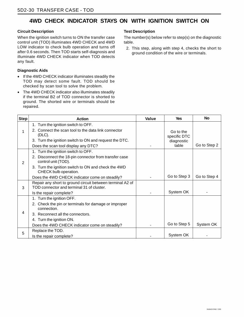
Circuit Description
When the ignition switch turns to ON the transfer casecontrol unit (TOD) illuminates 4WD CHECK and 4WDLOW indicator to check bulb operation and turns offafter 0.6 seconds. Then TOD starts self-diagnosis andilluminate 4WD CHECK indicator when TOD detectsany fault.
Diagnostic Aids
• If the 4WD CHECK indicator illuminates steadily theTOD may detect some fault. TOD should bechecked by scan tool to solve the problem.
• The 4WD CHECK indicator also illuminates steadilyif the terminal B2 of TOD connector is shorted toground. The shorted wire or terminals should berepaired.
Step
1
2
3
4
5
Action1. Turn the ignition switch to OFF.2. Connect the scan tool to the data link connector
(DLC).3. Turn the ignition switch to ON and request the DTC.Does the scan tool display any DTC?1. Turn the ignition switch to OFF.2. Disconnect the 18-pin connector from transfer case
control unit (TOD).3. Turn the ignition switch to ON and check the 4WD
CHECK bulb operation.Does the 4WD CHECK indicator come on steadily?Repair any short to ground circuit between terminal A2 ofTOD connector and terminal 31 of cluster.Is the repair complete?1. Turn the ignition OFF.2. Check the pin or terminals for damage or improper
connection.3. Reconnect all the connectors.4. Turn the ignition ON.Does the 4WD CHECK indicator come on steadily?Replace the TOD.Is the repair complete?
Yes
Go to thespecific DTCdiagnostic
table
Go to Step 3
System OK
Go to Step 5
System OK
No
Go to Step 2
Go to Step 4
-
System OK
-
Value
-
-
-
-
-
4WD CHECK INDICATOR STAYS ON WITH IGNITION SWITCH ON
Test Description
The number(s) below refer to step(s) on the diagnostictable.
2. This step, along with step 4, checks the short toground condition of the wire or terminals.

TRANSFER CASE - TOD 5D2-31
SSANGYONG Y200
Circuit Description
When the ignition switch turns to ON the transfer casecontrol unit (TOD) illuminates 4WD CHECK and 4WDLOW indicator to check bulb operation and turns offafter 0.6 seconds. Then TOD starts self-diagnosis andilluminate 4WD CHECK indicator when TOD detectsany fault.
Diagnostic Aids
• If the 4WD LOW indicator illuminates steadily thetransfer case in 4WD low range and 4H/4L switchset to 4L. It is normal condition.
• The 4WD LOW indicator also illuminates steadily ifthe terminal B9 of TOD connector is shorted toground. The shorted wire or terminals should berepaired.
4WD LOW INDICATOR STAYS ON WITH IGNITION SWITCH ON
Test Description
The number(s) below refer to step(s) on the diagnostictable.
2. This step checks for the normal bulb operation.
Value
-
-
-
-
-
-
-
Step
1
2
3
4
5
6
7
ActionCheck the position of 4H/4L switch.Does the 4H/4L switch set on 4L?1. Turn the ignition switch to ON.2. Set the shift lever to N (neutral).3. Turn the 4H/4L switch to 4H.Does the 4WD LOW indicator go off?1. Turn the ignition switch to ON.2. Set the shift lever to N (neutral).3. Turn the 4H/4L switch to 4L.Does the 4WD LOW indicator go off?The wiring of 4H/4L switch is reversed. Repair the wiring.Is the repair complete?1. Turn the ignition OFF.2. Check the pin or terminals for damage or improper
connection.3. Reconnect all the connectors.4. Turn the ignition ON.Does the 4WD LOW indicator come on steadily?Repair any short to ground circuit between terminal B9 ofTOD connector and terminal A13 of cluster.Is the repair complete?Replace the TOD.Is the repair complete?
Yes
Go to Step 2
System OK
Go to Step 4
System OK
Go to Step 6
System OK
System OK
No
Go to Step 3
-
Go to Step 5
-
System OK
Go to Step 7
-

SSANGYONG Y200
5D2-32 TRANSFER CASE - TOD
Circuit Description
When the ignition switch turns to ON the transfer casecontrol unit (TOD) illuminates 4WD CHECK and 4WDLOW indicator to check bulb operation and turns offafter 0.6 seconds. Then TOD starts self-diagnosis andilluminate 4WD CHECK indicator when TOD detectsany fault.
Diagnostic Aids
If the both of the 4WD CHECK and 4WD LOW indicatorwere not illuminating there would be some problemswith fuse, power supply line, improper connection ofconnector or transfer case control unit (TOD).
If one of the indicators illuminates, the fuse and powersupply line is good and the connector or TOD may bethe cause of problems.
NO 4WD CHECK OR 4WD LOW INDICATOR WITH IGNITION SWITCH ON
Test Description
The number(s) below refer to step(s) on the diagnostictable.
1. This step checks for the normal bulb operation.
5. This step checks voltage supply condition.
Yes
Go to Step 2
Go to Step 3
System OK
System OK
Go to Step 6
System OK
System OK
No
Go to Step 5
Go to Step 4
Go to Step 7
Go to Step 7
Go to Step 7
Go to Step 7
-
Value
-
-
-
-
-
-
-
Step
1
2
3
4
5
6
7
ActionCheck the bulb operation when the ignition switch turnsto ON.Does the only 4WD LOW indicator come on and goesafter 0.6 seconds?1. Turn the ignition switch to OFF.2. Disconnect 18-pin connector from the transfer case
control unit (TOD).3. Using test lamp check the continuity between terminal
B2 of TOD and ground.Does the test lamp come on?1. Turn the ignition OFF.2. Check the pin or terminals for damage or improper
connection.3. Reconnect all the connectors.4. Turn the ignition ON.Do the two indicators come on go after 0.6 seconds?Repair or replace of following components:
• 4WD CHECK indicator bulb.
• Open circuit between terminal A12 of cluster andterminal B2 of TOD connector.
Is the repair complete?1. Check the fuse F2 and indicator bulbs.2. Check the continuity for following terminals:
• Fuse F2 to B2 (TOD)
• A2 (Cluster) to B2 (TOD)
• B15 (Cluster) to B9 (TOD)Are there any problems?Repair open circuit or replace damaged parts.Is the repair complete?Replace the TOD.Is the repair complete?
TRANSFER CASE - TOD 5D2-33
SSANGYONG Y200
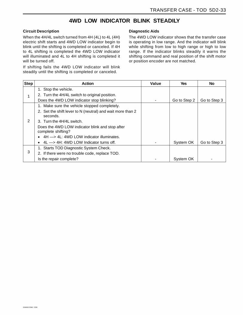
Circuit Description
When the 4H/4L switch turned from 4H (4L) to 4L (4H)electric shift starts and 4WD LOW indicator begin toblink until the shifting is completed or canceled. If 4Hto 4L shifting is completed the 4WD LOW indicatorwill illuminated and 4L to 4H shifting is completed itwill be turned off.
If shifting fails the 4WD LOW indicator will blinksteadily until the shifting is completed or canceled.
Diagnostic Aids
The 4WD LOW indicator shows that the transfer caseis operating in low range. And the indicator will blinkwhile shifting from low to high range or high to lowrange. If the indicator blinks steadily it warns theshifting command and real position of the shift motoror position encoder are not matched.
4WD LOW INDICATOR BLINK STEADILY
Yes
Go to Step 2
System OK
System OK
No
Go to Step 3
Go to Step 3
-
Value
-
-
-
Step
1
2
3
Action1. Stop the vehicle.2. Turn the 4H/4L switch to original position.Does the 4WD LOW indicator stop blinking?1. Make sure the vehicle stopped completely.2. Set the shift lever to N (neutral) and wait more than 2
seconds.3. Turn the 4H/4L switch.Does the 4WD LOW indicator blink and stop aftercomplete shifting?
• 4H —> 4L: 4WD LOW indicator illuminates.
• 4L —> 4H: 4WD LOW Indicator turns off.1. Starts TOD Diagnostic System Check.2. If there were no trouble code, replace TOD.Is the repair complete?

SSANGYONG Y200
5D2-34 TRANSFER CASE - TOD
EEPROM Checksum Fault
Circuit DescriptionWhen the ignition is turned on the transfer case controlunit (TOD) receives battery voltage and ignition volt-age and illuminates the 4WD CHECK and 4WD LOWindicators for 0.6 seconds. Then it starts self diagnosisto check itself.
Conditions for Setting the DTCDTC 1714 is an indication of a potential internal transfercase control unit (TOD) malfunction. It will set if any offollowing conditions is detected.
• The calculated checksum for internal memory doesnot match the stored value.
• The permanent memory storage area ismalfunctioning.
DIAGNOSTIC TROUBLE CODE (DTC) 1714
Action Taken When the DTC Sets
The TOD will illuminates 4WD CHECK indicator andDTC is stored in TOD.
Diagnostic Aids
• Check for poor connections, fuse and power supplywiring.
• Check for ground condition.
Test Description
The number(s) below refer to step(s) on the diagnostictable.
2. This step checks the battery supply voltage.
4. This step checks the ground condition.
6. This step checks the connection status.
Yes
Go to Step 2
Go to Step 4
Go to Step 4
Go to Step 6
Go to Step 6
NoGo To “TODControl UnitDiagnostic
SystemCheck”
Go to Step 3
-
Go to Step 5
-
Step
1
2
3
4
5
ActionWas the TOD Diagnostic System Check performed?
1. Turn the ignition switch OFF.2. Disconnect the 12-pin connector from transfer case
control unit (TOD).3. Turn the ignition switch to ON.4. Connect a digital voltmeter between each of the
following TOD connector terminal and ground.
• A4 (Battery supply)
• A11 (Battery supply)
• A5 (Battery supply)Does the voltage of the all circuits measure within thevalue specified?1. Check the fuse EF9 and voltage supply circuit.2. Repair or replace any open or damaged circuit or fuse.Is the repair complete?Connect a digital ohmmeter between each of thefollowing TOD connector terminal and ground.
• B9 (Ground).
• B2 (Ground).Does the resistance of the all circuits measure within thevalue specified?Repair or replace any open or damaged circuit.Is the repair complete?
Value
-
11 ~ 14 V
-
0 Ω
-
TRANSFER CASE - TOD 5D2-35
SSANGYONG Y200
Yes
Go to Step 7
System OK
No
System OK
-
Value
-
-
Step
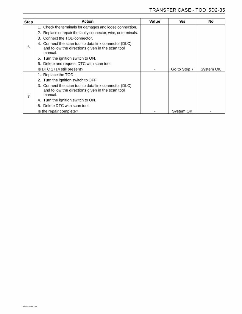
6
7
Action1. Check the terminals for damages and loose connection.2. Replace or repair the faulty connector, wire, or terminals.3. Connect the TOD connector.4. Connect the scan tool to data link connector (DLC)
and follow the directions given in the scan toolmanual.
5. Turn the ignition switch to ON.6. Delete and request DTC with scan tool.Is DTC 1714 still present?1. Replace the TOD.2. Turn the ignition switch to OFF.3. Connect the scan tool to data link connector (DLC)
and follow the directions given in the scan toolmanual.
4. Turn the ignition switch to ON.5. Delete DTC with scan tool.Is the repair complete?

SSANGYONG Y200
5D2-36 TRANSFER CASE - TOD
TP Sensor Loss of Signal
Circuit DescriptionThe transfer case control unit (TOD) receives throttleposition (TP) sensor signals from engine control module(ECM) through CAN bus line.
Conditions for Setting the DTCThe transfer case control unit (TOD) can not receivethrottle position (TP) sensor signal from engine controlmodule (ECM). There is a bad communication betweenTOD and ECM.
• TOD is malfunction.
• ECM is malfunction.
DIAGNOSTIC TROUBLE CODE (DTC) 1715
Action Taken When the DTC Sets
The TOD will illuminates 4WD CHECK indicator andDTC is stored in TOD.
Diagnostic Aids
• Check for poor connections of CAN bus line.
• Check for ECM and TP sensor.
Test Description
The number(s) below refer to step(s) on the diagnostictable.
2. This step decides the causal parts of the problem.
4. This step checks the ground condition.
6. This step checks the connection status.
Yes
Go to Step 2
Go to “TODDiagnostic
SystemCheck”Refer toSectionEngine
Go to Step 5
System OK
No
Go to “TODDiagnostic
SystemCheck”
Go to Step 3
Go to Step 4
-
Value
-
-
0 Ω
-
Step
1
2
3
4
Action
Was the TOD Diagnostic System Check performed?
1. Turn the ignition switch to OFF.2. Connect the scan tool to data link connector (DLC)
and follow the directions given in the scan toolmanual.
3. Turn the ignition switch to ON and request engineDTC.
Are there any engine DTC related throttle position (TP)sensor?1. Turn the ignition switch to OFF.2. Disconnect the 18-pin connector from the transfer
case control unit (TOD).3. Disconnect the gray connector from engine control
module (ECM).4. Connect a digital ohmmeter between the following
TOD connector terminal and gray ECM connectorterminal.
• B11 (TOD) and 37 (ECM)
• B10 (TOD) and 38 (ECM)
• B11 (TOD) and 24 (ECM)
• B10 (TOD) and 23 (ECM)Does the resistance of the all circuits measure within thevalue specified?Repair or replace any open wires, faulty connector, orterminal.Is the repair complete?
TRANSFER CASE - TOD 5D2-37
SSANGYONG Y200
Yes
System OK
System OK
No
Go to Step 6
-
Value
-
-
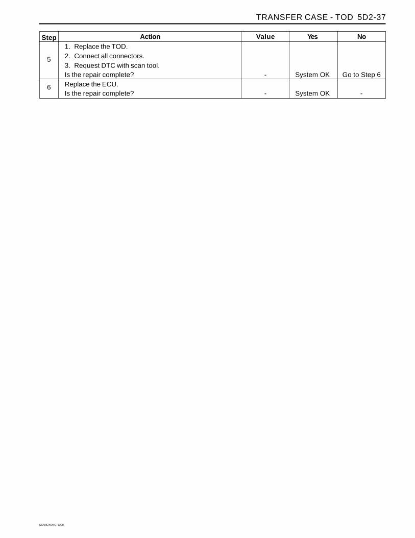
Step
5
6
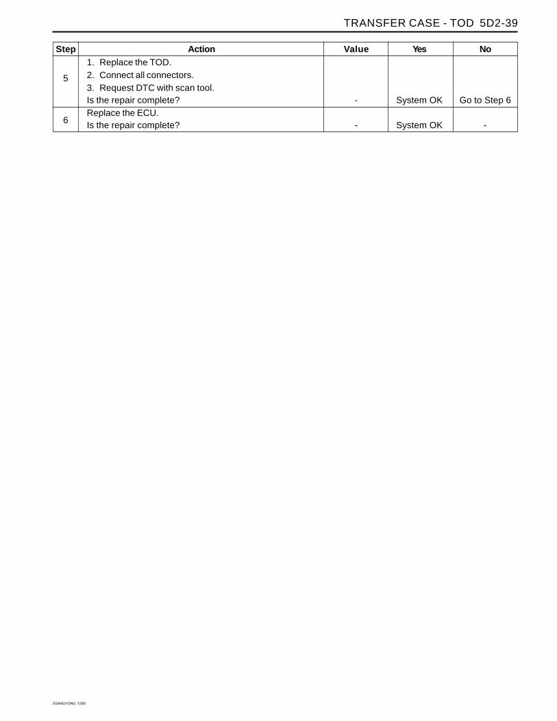
Action1. Replace the TOD.2. Connect all connectors.3. Request DTC with scan tool.Is the repair complete?Replace the ECU.Is the repair complete?

SSANGYONG Y200
5D2-38 TRANSFER CASE - TOD
TP Sensor Out of Range
Circuit DescriptionThe transfer case control unit (TOD) receives throttleposition (TP) sensor signals from engine control module(ECM) through CAN bus line.
Conditions for Setting the DTCD The transfer case control unit (TOD) receives throttleposition (TP) sensor signal from engine control module(ECM), but the signal is out of the range.
There is a bad communication between TOD and ECU.
• TOD is malfunction.
• ECU is malfunction.
DIAGNOSTIC TROUBLE CODE (DTC) 1716
Action taken When the DTC Sets
The TOD will illuminates 4WD CHECK indicator andDTC is stored in TOD.
Diagnostic Aids
Check for poor connections of CAN bus line.
Check for ECU and TP sensor.
Test Description
The number(s) below refer to step(s) on the diagnostictable.
2. This step decides the causal parts of the problem.
4. This step checks the ground condition.
6. This step checks the connection status.
Yes
Go to Step 2Go to “TODDiagnostic
SystemCheck”
Go to specificengine DTCdiagnosis.
Go to Step 4
System OK
NoGo to “TODDiagnostic
SystemCheck”
Go to Step 2
Go to Step 5
-
Value
-
-
0 Ω
-
Step
1
2
3
4
ActionWas the TOD Diagnostic System Check performed?
1. Turn the ignition switch to OFF.2. Connect the scan tool to data link connector (DLC)
and follow the directions given in the scan toolmanual.
3. Turn the ignition switch to ON and request engineDTC.
Are there any engine DTC related throttle position (TP)sensor?1. Turn the ignition switch to OFF.2. Disconnect the 18-pin connector from the transfer
case control unit (TOD).3. Disconnect the gray connector from engine control
module (ECU).4. Connect a digital ohmmeter between the following
TOD connector terminal and gray ECU connectorterminal.
• B11 (TOD) and 38 (ECU)
• B10 (TOD) and 37 (ECU)
• B11 (TOD) and A24
• B10 (TOD) and A23
• B11 (TOD) and ground
• B10 (TOD) and groundDoes the resistance of the all circuits measure within thevalue specified?Repair or replace any short wires, faulty connector, orterminal.Is the repair complete?
TRANSFER CASE - TOD 5D2-39
SSANGYONG Y200
Yes
System OK
System OK
No
Go to Step 6
-
Value
-
-
Step
5
6
Action1. Replace the TOD.2. Connect all connectors.3. Request DTC with scan tool.Is the repair complete?Replace the ECU.Is the repair complete?

SSANGYONG Y200
5D2-40 TRANSFER CASE - TOD
Electromagnetic Clutch Open / Short toBattery
Circuit Description
To control the distribution of the torque to front propellershaft, the transfer case control unit (TOD) sends asignal to the electromagnetic clutch (EMC). Then theclutch disc is compressed or released by the EMC.
Conditions for Setting the DTC
Even the TOD send signal for controlling the EMC, itreceives uncontrolled propeller shaft speed signal.
• The wiring circuit to EMC opened.
• The wiring circuit is shorted to battery.
Action Taken When the DTC SetsThe TOD will illuminates 4WD CHECK indicator andDTC is stored in TOD.
DIAGNOSTIC TROUBLE CODE (DTC) 1721
Diagnostic Aids
• Check for poor connections of the circuit.
• Check for EMC.
Test Description
The number(s) below refer to step(s) on the diagnostictable.
2. This step checks poor connection or damage onthe pin.
3. This step, along with step 4, checks the voltagesupply condition.
5. This step checks the ground condition.
7. This step checks the continuity of the wire andshort to battery condition.
Step
1
2
3
Yes
Go to Step 2
Go to Step 3
Go to Step 5
NoGo to “TODDiagnostic
SystemCheck”
System OK
Go to Step 4
Value
-
-
11 ~ 14 V
ActionWas the TOD Diagnostic System Check performed?
1. Turn the ignition switch to OFF.2. Disconnect two connectors of the transfer case
control unit (TOD) and white 7-pin connector, forpropeller shaft speed sensor and clutch coil, locatedunder the body.
3. Inspect the terminals for damage or improper connection.4. Repair any damaged pins or terminals on the wiring
harness and TOD.5. Reconnect the connectors and make sure it is seated
properly.6. Connect a scan tool to the data link connector (DLC).7. Turn the ignition ON.8. Request the DTC with scan tool.Is the DTC still current?1. Turn the ignition switch to OFF.2. Disconnect the 12-pin connector from transfer case
control unit (TOD).3. Turn the ignition switch to ON.4. Connect a digital voltmeter between each of the
following TOD connector terminal and ground.
• A4 (Battery supply).
• A11 (Battery supply).Does the voltage of the all circuits measure within thevalue specified?
TRANSFER CASE - TOD 5D2-41
SSANGYONG Y200
Step
4
5
6
7
8
9
10
11
Yes
Go to Step 5
Go to Step 7
Go to Step 7
Go to Step 9
System OK
Go to Step 11
System OK
System OK
No
-
Go to Step 6
-
Go to Step 8
-
Go to Step 10
-
-
Value
-
0 Ω
-
12
-
2.2 ~ 2.8 Ω
-
-
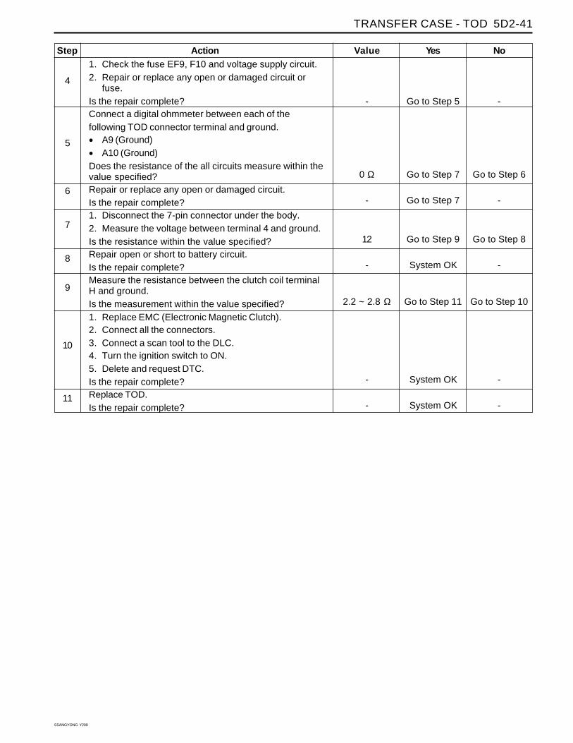
Action1. Check the fuse EF9, F10 and voltage supply circuit.2. Repair or replace any open or damaged circuit or
fuse.Is the repair complete?Connect a digital ohmmeter between each of thefollowing TOD connector terminal and ground.
• A9 (Ground)
• A10 (Ground)Does the resistance of the all circuits measure within thevalue specified?Repair or replace any open or damaged circuit.Is the repair complete?1. Disconnect the 7-pin connector under the body.2. Measure the voltage between terminal 4 and ground.Is the resistance within the value specified?Repair open or short to battery circuit.Is the repair complete?Measure the resistance between the clutch coil terminalH and ground.Is the measurement within the value specified?1. Replace EMC (Electronic Magnetic Clutch).2. Connect all the connectors.3. Connect a scan tool to the DLC.4. Turn the ignition switch to ON.5. Delete and request DTC.Is the repair complete?Replace TOD.Is the repair complete?

SSANGYONG Y200
5D2-42 TRANSFER CASE - TOD
Electromagnetic Clutch Short to Ground
Circuit DescriptionTo control the distribution of the torque to front propellershaft, the transfer case control unit (TOD) sends asignal to the electromagnetic clutch (EMC). Then theclutch disc is compressed or released by the EMC.
Conditions for Setting the DTCEven the TOD send signal for controlling the EMC, itreceives uncontrolled propeller shaft speed signal.
• The wiring circuit to EMC is shorted to ground.
Action Taken When the DTC Sets
The TOD will illuminates 4WD CHECK indicator andDTC is stored in TOD.
DIAGNOSTIC TROUBLE CODE (DTC) 1722
Diagnostic Aids
• Check for poor connections of the circuit.
• Check for EMC.
Test Description
The number(s) below refer to step(s) on the diagnostictable.
2. This step checks poor connection or damage onthe pin.
3. This step, along with step 4, checks the voltagesupply condition.
5. This step checks the ground condition.
7. This step checks the continuity of the wire andshort to battery condition.
Yes
Go to Step 2
Go to Step 3
Go to Step 5
Go to Step 5
Step
1
2
3
4
No
Go to “TODDiagnostic
SystemCheck”
System OK
Go to Step 4
-
Value
-
-
11 ~ 14 V
-
Action
Was the TOD Diagnostic System Check performed?
1. Turn the ignition switch to OFF.2. Disconnect two connectors of the transfer case
control unit (TOD) and white 7-pin connector, forpropeller shaft speed sensor and clutch coil, locatedunder the body.
3. Inspect the terminals for damage or improper connection.4. Repair any damaged pins or terminals on the wiring
harness and TOD.5. Reconnect the connectors and make sure it is seated
properly.6. Connect a scan tool to the data link connector (DLC).7. Turn the ignition ON.8. Request the DTC with scan tool.Is the DTC still current?1. Turn the ignition switch to OFF.2. Disconnect the 12-pin connector from transfer case
control unit (TOD).3. Turn the ignition switch to ON.4. Connect a digital voltmeter between each of the
following TOD connector terminal and ground.
• A4 (Battery supply).
• A11 (Battery supply).Does the voltage of the all circuits measure within thevalue specified?1. Check the fuse EF9, F10 and voltage supply circuit.2. Repair or replace any open or damaged circuit or
fuse.Is the repair complete?

TRANSFER CASE - TOD 5D2-43
SSANGYONG Y200
Step
5
6
7
8
9
10
11
Yes
Go to Step 7
Go to Step 7
Go to Step 9
System OK
Go to Step 11
System OK
System OK
No
Go to Step 6
-
Go to Step 8
-
Go to Step 10
-
-
Value
0 Ω
-
0 Ω
-
2.2 ~ 2.8 Ω
-
-
ActionConnect a digital ohmmeter between each of thefollowing TOD connector terminal and ground.
• A9 (Ground)
• A10 (Ground)Does the resistance of the all circuits measure within thevalue specified?Repair or replace any open or damaged circuit.Is the repair complete?1. Disconnect the 7-pin connector under the body.2. Measure the voltage between terminal 4 and ground.Is the resistance within the value specified?Repair open or short to battery circuit.Is the repair complete?Measure the resistance between the clutch coil terminalH and ground.Is the measurement within the value specified?1. Replace EMC (Electronic Magnetic Clutch).2. Connect all the connectors.3. Connect a scan tool to the DLC.4. Turn the ignition switch to ON.5. Delete and request DTC.Is the repair complete?Replace TOD.Is the repair complete?

SSANGYONG Y200
5D2-44 TRANSFER CASE - TOD
Front Speed Sensor Voltage Low
Circuit DescriptionThe transfer case control unit (TOD) supplies 5 voltsreference voltage to the front speed sensor andreceives speed signals generated by Hall effect speedsensor.
Conditions for Setting the DTC
• The wiring circuit for speed sensor shorted to groundor opened.
• The reference voltage circuit is shorted to groundor opened.
Action Taken When the DTC Sets
The TOD will illuminates 4WD CHECK indicator andDTC is stored in TOD.
The TOD then responds as follows:
• If the system is in high range the TOD uses therear speed sensor to determine the EMC touch offlevel and wheel slip control is suspended.
• If the system is in low range, the EMC duty cycle isset to maximum, independent of vehicle speed, untilthe system is shifted out of low range.
• All electric shift activity is halted until the Ignitionis cycled. If a shift is in progress it wil l becompleted.
DIAGNOSTIC TROUBLE CODE (DTC) 1731
Diagnostic Aids
• Check for short to ground or open circuit.
• Check for front propeller speed sensor.
Test Description
The number(s) below refer to step(s) on the diagnostictable.
3. This step checks the continuity.
5. This step checks the speed sensor.
Value
-
-
0 Ω
∞
Step
1
2
3
Yes
Go to Step 2
Go to “DTC1735 – Speed
SensorReference
Voltage Low”
Go to Step 5
NoGo to “TODDiagnostic
SystemCheck”
Go to Step 3
Go to Step 4
ActionWas the TOD Diagnostic System Check performed?
1. Turn the ignition switch to OFF.2. Connect a scan tool to the data link connector (DLC)
and follow the directions given in the scan toolmanual.
3. Turn the ignition switch to ON.4. Request DTC with scan tool.Is the DTC 1735 also shown?1. Turn the ignition switch to OFF.2. Disconnect 18-pin connectors of the transfer case
control unit (TOD) and white 7-pin connector, forpropeller shaft speed sensor and clutch coil, locatedunder the body.
3. Measure the resistance between terminals B6 andterminals of the 7-pin connector.
4. Measure the resistance between terminals B6 andground.
Is measured value equal to specified range?

TRANSFER CASE - TOD 5D2-45
SSANGYONG Y200
Step
4
5
6
7
Yes
Go to Step 5
Go to Step 7
System OK
System OK
No
System OK
Go to Step 6
-
-
Value
-
5 ~ 6 MΩ5 ~ 6 MΩ
9 ~ 10 MΩ
-
-
Action1. Repair any damaged pins, terminals, open or short to
ground circuit.2. Reconnect the connectors and make sure it is seated
properly.3. Connect a scan tool to the data link connector (DLC).4. Turn the ignition ON.5. Request the DTC with scan tool.Is the DTC still current?Measure the resistance between terminals of the malewhite 7-pin connector.Is the measurement within specified range?
• Terminal 6 and terminal 3
• Terminal 6 and terminal 2
• Terminal 3 and terminal 2Replace front propeller shaft speed sensor.Is the repair complete?1. Replace the TOD.2. Turn the ignition switch to OFF.3. Connect the scan tool to data link connector (DLC)
and follow the directions given in the scan toolmanual.
4. Turn the ignition switch to ON.5. Delete and request DTC with scan tool.Is the repair complete?

SSANGYONG Y200
5D2-46 TRANSFER CASE - TOD
DIAGNOSTIC TROUBLE CODE (DTC) 1732
Diagnostic Aids
• Check for short to ground or open circuit.
• Check for front propeller speed sensor.
Test Description
The number(s) below refer to step(s) on the diagnostictable.
3. This step checks the continuity.
5. This step checks the speed sensor.
Step
1
2
3
Yes
Go to Step 2
Go to “DTC1736 – Speed
SensorReference
Voltage High”
Go to Step 5
NoGo to “TODDiagnostic
SystemCheck”
Go to Step 3
Go to Step 4
ActionWas the TOD Diagnostic System Check performed?
1. Turn the ignition switch to OFF.2. Connect a scan tool to the data link connector (DLC)
and follow the directions given in the scan toolmanual.
3. Turn the ignition switch to ON.4. Request DTC with scan tool.Is the DTC 1736 also shown?1. Turn the ignition switch to OFF.2. Disconnect 18-pin connectors of the transfer case
control unit (TOD) and white 7-pin connector, forpropeller shaft speed sensor and clutch coil, locatedunder the body.
3. Measure the voltage between terminals B6 andground.
Is measured value below the specified value?
Value
-
-
0 Ω
Front Speed Sensor Voltage High
Circuit DescriptionThe transfer case control unit (TOD) supplies 5 voltsreference voltage to the front speed sensor andreceives speed signals generated by Hall effect speedsensor.
Conditions for Setting the DTC
• The wiring circuit for speed sensor shorted tovoltage.
• The reference voltage circuit is shorted to voltage.
Action Taken When the DTC Sets
The TOD will illuminates 4WD CHECK indicator andDTC is stored in TOD.
The TOD then responds as follows:
• If the system is in high range the TOD uses therear speed sensor to determine the EMC touch offlevel and wheel slip control is suspended.
• If the system is in low range, the EMC duty cycle isset to maximum, independent of vehicle speed, untilthe system is shifted out of low range.
• All electric shift activity is halted until the Ignitionis cycled. If a shift is in progress it wil l becompleted.
TRANSFER CASE - TOD 5D2-47
SSANGYONG Y200
Step
4
5
6
7
Yes
Go to Step 5
Go to Step 7
System OK
System OK
No
System OK
Go to Step 6
-
-
Value
-
5 ~ 6 MΩ5 ~ 6 MΩ9 ~ 10 kΩ
-
-
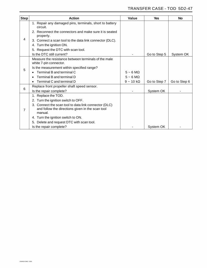
Action1. Repair any damaged pins, terminals, short to battery
circuit.2. Reconnect the connectors and make sure it is seated
properly.3. Connect a scan tool to the data link connector (DLC).4. Turn the ignition ON.5. Request the DTC with scan tool.Is the DTC still current?Measure the resistance between terminals of the malewhite 7-pin connector.Is the measurement within specified range?
• Terminal B and terminal C
• Terminal B and terminal D
• Terminal C and terminal DReplace front propeller shaft speed sensor.Is the repair complete?1. Replace the TOD.2. Turn the ignition switch to OFF.3. Connect the scan tool to data link connector (DLC)
and follow the directions given in the scan toolmanual.
4. Turn the ignition switch to ON.5. Delete and request DTC with scan tool.Is the repair complete?

SSANGYONG Y200
5D2-48 TRANSFER CASE - TOD
DIAGNOSTIC TROUBLE CODE (DTC) 1733
Rear Speed Sensor Voltage Low
Circuit DescriptionThe transfer case control unit (TOD) supplies 5 voltsreference voltage to the front and rear speed sensorand receives speed signals generated by Hall effectspeed sensor.
Conditions for Setting the DTC
• The wiring circuit for speed sensor shorted to groundor opened.
• The reference voltage circuit is shorted to groundor opened.
Action Taken When the DTC Sets
The TOD will illuminates 4WD CHECK indicator andDTC is stored in TOD.
The TOD then responds as follows:
• If the system is in high range the TOD uses thefront speed sensor to determine the EMC touch offlevel and wheel slip control is suspended.
• If the system is in low range, the EMC duty cycle isset to maximum independent of vehicle speed untilthe system is shifted out of low range.
• All electric shift activity is halted until the Ignitionis cycled. If a shift is in progress it wil l becompleted.
Diagnostic Aids
• Check for short to ground or open circuit.
• Check for front propeller speed sensor.
Test Description
The number(s) below refer to step(s) on the diagnostictable.
3. This step checks the continuity.
5. This step checks the speed sensor.
Step
1
2
3
Yes
Go to Step 2
Go to “DTC1735 – Speed
SensorReference
Voltage Low”
Go to Step 5
NoGo to “TODDiagnostic
SystemCheck”
Go to Step 3
Go to Step 4
ActionWas the TOD Diagnostic System Check performed?
1. Turn the ignition switch to OFF.2. Connect a scan tool to the data link connector (DLC)
and follow the directions given in the scan toolmanual.
3. Turn the ignition switch to ON.4. Request DTC with scan tool.Is the DTC 1736 also shown?1. Turn the ignition switch to OFF.2. Disconnect 18-pin connectors of the transfer case
control unit (TOD) and white 7-pin connector, forpropeller shaft speed sensor and clutch coil, locatedunder the body.
3. Measure the resistance between terminals 17 of TODand terminals in female white 7-pin connector.
Is measured value equal to specified range?4. Measure the resistance between terminals B17 of
TOD and ground.Is measured value equal to specified range?
Value
-
-
0 Ω
∞

TRANSFER CASE - TOD 5D2-49
SSANGYONG Y200
Step
4
5
6
7
Yes
Go to Step 5
Go to Step 7
System OK
System OK
No
System OK
Go to Step 6
-
-
Value
-
5 ~ 6 MΩ5 ~ 6 MΩ9 ~ 10 kΩ
-
-
Action1. Repair any damaged pins, terminals, open or short to
ground circuit.2. Reconnect the connectors and make sure it is seated
properly.3. Connect a scan tool to the data link connector (DLC).4. Turn the ignition ON.5. Request the DTC with scan tool.Is the DTC still current?Measure the resistance between terminals of the malewhite 7-pin connector.Is the measurement within specified range?
• Terminal 7 and terminal 5
• Terminal 7 and terminal 1
• Terminal 5 and terminal 1Replace rear propeller shaft speed sensor.Is the repair complete?1. Replace the TOD.2. Turn the ignition switch to OFF.3. Connect the scan tool to data link connector (DLC)
and follow the directions given in the scan toolmanual.
4. Turn the ignition switch to ON.5. Delete and request DTC with scan tool.Is the repair complete?

SSANGYONG Y200
5D2-50 TRANSFER CASE - TOD
DIAGNOSTIC TROUBLE CODE (DTC) 1734
Rear Speed Sensor Voltage High
Circuit DescriptionThe transfer case control unit (TOD) supplies 5 voltsreference voltage to the front speed sensor andreceives speed signals generated by Hall effect speedsensor.
Conditions for Setting the DTC
• The wiring circuit for speed sensor shorted tovoltage.
• The reference voltage circuit is shorted to voltage.
Action Taken When the DTC Sets
The TOD will illuminates 4WD CHECK indicator andDTC is stored in TOD.
The TOD then responds as follows:
• If the system is in high range the TOD uses thefront speed sensor to determine the EMC touch offlevel and wheel slip control is suspended.
• If the system is in low range, the EMC duty cycle isset to maximum independent of vehicle speed untilthe system is shifted out of low range.
• All electric shift activity is halted until the Ignitionis cycled. If a shift is in progress it wil l becompleted.
Diagnostic Aids
• Check for short to ground or open circuit.
• Check for front propeller speed sensor.
Test Description
The number(s) below refer to step(s) on the diagnostictable.
3. This step checks the continuity.
5. This step checks the speed sensor.
Step
1
2
3
Yes
Go to Step 2
Go to “DTC1736 - Speed
SensorReference
Voltage High”
Go to Step 5
NoGo to “TODDiagnostic
SystemCheck”
Go to Step 3
Go to Step 4
ActionWas the TOD Diagnostic System Check performed?
1. Turn the ignition switch to OFF.2. Connect a scan tool to the data link connector (DLC)
and follow the directions given in the scan toolmanual.
3. Turn the ignition switch to ON.4. Request DTC with scan tool.Is the DTC 1736 also shown?1. Turn the ignition switch to OFF.2. Disconnect 18-pin connectors of the transfer case
control unit (TOD) and white 7-pin connector, forpropeller shaft speed sensor and clutch coil, locatedunder the body.
3. Measure the voltage between terminals B17 of TODand ground.
Is measured value below the specified value?
Value
-
-
0 Ω

TRANSFER CASE - TOD 5D2-51
SSANGYONG Y200
Step
4
5
6
7
Yes
Go to Step 5
Go to Step 7
System OK
System OK
No
System OK
Go to Step 6
-
Value
-
5 ~ 6 MΩ5 ~ 6 MΩ9 ~ 10 kΩ
-
-
Action1. Repair any damaged pins, terminals, open or short to
ground circuit.2. Reconnect the connectors and make sure it is seated
properly.3. Connect a scan tool to the data link connector (DLC).4. Turn the ignition ON.5. Request the DTC with scan tool.Is the DTC still current?Measure the resistance between terminals of the malewhite 7-pin connector.Is the measurement within specified range?
• Terminal 7 and terminal 5
• Terminal 7 and terminal 1
• Terminal 5 and terminal 1Replace rear propeller shaft speed sensor.Is the repair complete?1. Replace the TOD.2. Turn the ignition switch to OFF.3. Connect the scan tool to data link connector (DLC)
and follow the directions given in the scan toolmanual.
4. Turn the ignition switch to ON.5. Delete and request DTC with scan tool.Is the repair complete?
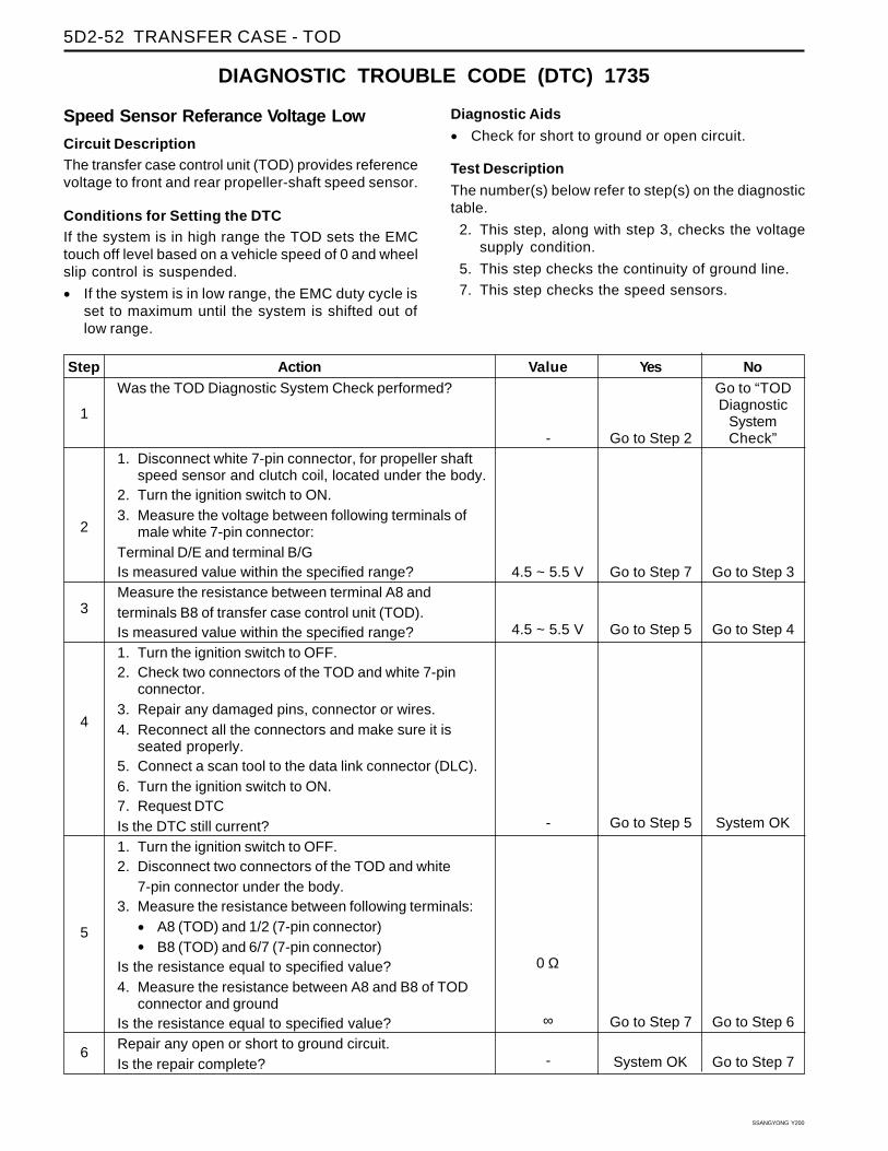
SSANGYONG Y200
5D2-52 TRANSFER CASE - TOD
DIAGNOSTIC TROUBLE CODE (DTC) 1735
Speed Sensor Referance Voltage Low
Circuit DescriptionThe transfer case control unit (TOD) provides referencevoltage to front and rear propeller-shaft speed sensor.
Conditions for Setting the DTCIf the system is in high range the TOD sets the EMCtouch off level based on a vehicle speed of 0 and wheelslip control is suspended.
• If the system is in low range, the EMC duty cycle isset to maximum until the system is shifted out oflow range.
Diagnostic Aids
• Check for short to ground or open circuit.
Test Description
The number(s) below refer to step(s) on the diagnostictable.
2. This step, along with step 3, checks the voltagesupply condition.
5. This step checks the continuity of ground line.
7. This step checks the speed sensors.
Step
1
2
3
4
5
6
Yes
Go to Step 2
Go to Step 7
Go to Step 5
Go to Step 5
Go to Step 7
System OK
NoGo to “TODDiagnostic
SystemCheck”
Go to Step 3
Go to Step 4
System OK
Go to Step 6
Go to Step 7
Value
-
4.5 ~ 5.5 V
4.5 ~ 5.5 V
-
0 Ω
∞
-
ActionWas the TOD Diagnostic System Check performed?
1. Disconnect white 7-pin connector, for propeller shaftspeed sensor and clutch coil, located under the body.
2. Turn the ignition switch to ON.3. Measure the voltage between following terminals of
male white 7-pin connector:Terminal D/E and terminal B/GIs measured value within the specified range?Measure the resistance between terminal A8 andterminals B8 of transfer case control unit (TOD).Is measured value within the specified range?1. Turn the ignition switch to OFF.2. Check two connectors of the TOD and white 7-pin
connector.3. Repair any damaged pins, connector or wires.4. Reconnect all the connectors and make sure it is
seated properly.5. Connect a scan tool to the data link connector (DLC).6. Turn the ignition switch to ON.7. Request DTCIs the DTC still current?1. Turn the ignition switch to OFF.2. Disconnect two connectors of the TOD and white
7-pin connector under the body.3. Measure the resistance between following terminals:
• A8 (TOD) and 1/2 (7-pin connector)
• B8 (TOD) and 6/7 (7-pin connector)Is the resistance equal to specified value?4. Measure the resistance between A8 and B8 of TOD
connector and groundIs the resistance equal to specified value?Repair any open or short to ground circuit.Is the repair complete?

TRANSFER CASE - TOD 5D2-53
SSANGYONG Y200
Step
7
8
9
Yes
Go to Step 9
System OK
System OK
No
Go to Step 8
-
-
Value
5 ~ 6 MΩ5 ~ 6 MΩ9 ~ 10 kΩ5 ~ 6 MΩ5 ~ 6 MΩ9 ~ 10 kΩ
-
-
ActionMeasure the resistance between terminals of the malewhite 7-pin connector.
• Terminal 6 and terminal 3
• Terminal 6 and terminal 2
• Terminal 3 and terminal 2
• Terminal 7 and terminal 5
• Terminal 7 and terminal 1
• Terminal 5 and terminal 1Is the measurement within specified range?Replace front or rear propeller shaft speed sensor.Is the repair complete?1. Replace the TOD.2. Turn the ignition switch to OFF.3. Connect the scan tool to data link connector (DLC)
and follow the directions given in the scan toolmanual.
4. Turn the ignition switch to ON.5. Delete and request DTC with scan tool.Is the repair complete?