Trans-Abdominal Active Magnetic Linkage for … abdominal Active Magnetic Linkage for Robotic...
6
Abstract— The novel concept of Trans-abdominal Active Magnetic Linkage for laparoendoscopic single site surgery has the potential to enable the deployment of a bimanual robotic platform trough a single laparoscopic incision. The main advantage of this approach consists in shifting the actuators outside the body of the patient, while transmitting a controlled robotic motion by magnetic field across the abdomen without the need for dedicated incisions. An actuation mechanism based on this approach can be comprised of multiple anchoring and actuation units, mixed depending upon the specific needs. A static model providing anchoring and actuation forces and torques available at the internal side of the magnetic link was developed to provide a tool to navigate among the many possibilities of such an open ended design approach. The model was assessed through bench top experiments, showing a maximum relative error of 4% on force predictions. An example of a single degree of freedom manipulator actuated with the proposed concept and compatible with a 12-mm access port is able to provide an anchoring force of 3.82 N and an actuation force of 2.95 N. I. INTRODUCTION OBOTIC surgery is currently a popular, widely accepted clinical practice, thanks to the large scale use of the Intuitive Surgical’s Da Vinci platform [1]. The next generation of surgical robots should guarantee the same dexterity and performance, while reducing access trauma. A promising approach in this direction is represented by robotic platforms specifically developed for (or adapted to) laparoendoscopic single site (LESS) surgery [2-5]. Actuation for the several degrees of freedom (DoFs) may be external, by means of cables [2, 3], internal, using on-board motors [4], or hybrid [5]. In these cases, the mechanical continuity of the kinematic chain constrains the workspace to the proximity of the insertion point. Having the single components of the platform, i.e. at least 2 manipulators and one camera, magnetically linked across the abdominal wall as in [6], would greatly enhance both freedom of operation and triangulation. However, in the previous works, robotic manipulators based on this kind of approach were always actuated by on-board electromagnetic motors [6, 7]. Assuming that the available power (torque x velocity) in Manuscript received September 16, 2011. This work was supported in part by European Commission in the framework of the ARAKNES European Project EU/IST-2008-224565. C. Di Natali and P. Valdastri are with the STORM Lab, Mechanical Engineering Department, Vanderbilt University, Nashville, TN, USA; T. Ranzani, M. Simi, A. Menciassi are with the BioRobotics Institute, Scuola Superiore Sant’Anna, Pisa, Italy. P. Valdastri is the corresponding author. such an actuator scales with mass and volume, the motors that can fit a tiny single incision, as desirable in LESS, have very limited performance. This limits the effectiveness of the platforms proposed in [6, 7, 8] for real-time teleoperation of a surgical task. Larger, more powerful motors can be used at the price of enlarging the access port [5]. For that reason, a novel kind of robotic actuation is desirable to achieve a concrete step ahead in robotic surgery. In particular, moving the actuators outside of the body, but still taking advantage of the reduced access trauma guaranteed by a trans- abdominal magnetic coupling, would provide dexterity, while preventing the need for powerful on-board motors. A first step, and straightforward approach, towards meeting this goal can be realized by mounting permanent magnets to the end effectors (EE) of industrial robotic arms. As represented in Fig. 1, two manipulators and one camera can be introduced into the abdomen by a single incision, as demonstrated in [6], and each can be coupled with an external magnet held by a robotic arm. If the EE and the internal modules are properly designed, up to 5 degrees of freedom (DoF) can be transmitted by moving the external permanent magnet (EPM). Referring to the left arm in Fig. 1, roll and X Y translation will work against the friction of the internal module on the abdominal wall, while pitch and yaw must counteract the elasticity of the abdominal tissue. Having the EPM driven by a robotic arm would provide a better precision of movement, however, the dynamic interaction with the abdominal wall will always introduce unreliability in the control loop. Therefore, the best use of this approach may be gross positioning before starting a procedure, i.e. when high precision and repeatability of movements are not a stringent requirement. Trans-abdominal Active Magnetic Linkage for Robotic Surgery: Concept Definition and Model Assessment C. Di Natali, Student Member, IEEE, T. Ranzani, Student Member, IEEE, M. Simi, Student Member, IEEE, A. Menciassi, Member, IEEE, P. Valdastri, Member, IEEE R Fig. 1. Concept of a magnetically actuated surgical platform. On the left are shown the several DoF that can be obtained by simple magnetic coupling. 2012 IEEE International Conference on Robotics and Automation RiverCentre, Saint Paul, Minnesota, USA May 14-18, 2012 978-1-4673-1404-6/12/$31.00 ©2012 IEEE 695
Transcript of Trans-Abdominal Active Magnetic Linkage for … abdominal Active Magnetic Linkage for Robotic...

Abstract— The novel concept of Trans-abdominal Active Magnetic Linkage for laparoendoscopic single site surgery has the potential to enable the deployment of a bimanual robotic platform trough a single laparoscopic incision. The main advantage of this approach consists in shifting the actuators outside the body of the patient, while transmitting a controlled robotic motion by magnetic field across the abdomen without the need for dedicated incisions. An actuation mechanism based on this approach can be comprised of multiple anchoring and actuation units, mixed depending upon the specific needs. A static model providing anchoring and actuation forces and torques available at the internal side of the magnetic link was developed to provide a tool to navigate among the many possibilities of such an open ended design approach. The model was assessed through bench top experiments, showing a maximum relative error of 4% on force predictions. An example of a single degree of freedom manipulator actuated with the proposed concept and compatible with a 12-mm access port is able to provide an anchoring force of 3.82 N and an actuation force of 2.95 N.
I. INTRODUCTION OBOTIC surgery is currently a popular, widely accepted clinical practice, thanks to the large scale use
of the Intuitive Surgical’s Da Vinci platform [1]. The next generation of surgical robots should guarantee the same dexterity and performance, while reducing access trauma. A promising approach in this direction is represented by robotic platforms specifically developed for (or adapted to) laparoendoscopic single site (LESS) surgery [2-5]. Actuation for the several degrees of freedom (DoFs) may be external, by means of cables [2, 3], internal, using on-board motors [4], or hybrid [5]. In these cases, the mechanical continuity of the kinematic chain constrains the workspace to the proximity of the insertion point. Having the single components of the platform, i.e. at least 2 manipulators and one camera, magnetically linked across the abdominal wall as in [6], would greatly enhance both freedom of operation and triangulation. However, in the previous works, robotic manipulators based on this kind of approach were always actuated by on-board electromagnetic motors [6, 7]. Assuming that the available power (torque x velocity) in
Manuscript received September 16, 2011. This work was supported in part by European Commission in the framework of the ARAKNES European Project EU/IST-2008-224565. C. Di Natali and P. Valdastri are with the STORM Lab, Mechanical Engineering Department, Vanderbilt University, Nashville, TN, USA; T. Ranzani, M. Simi, A. Menciassi are with the BioRobotics Institute, Scuola Superiore Sant’Anna, Pisa, Italy. P. Valdastri is the corresponding author.
such an actuator scales with mass and volume, the motors that can fit a tiny single incision, as desirable in LESS, have very limited performance. This limits the effectiveness of the platforms proposed in [6, 7, 8] for real-time teleoperation of a surgical task. Larger, more powerful motors can be used at the price of enlarging the access port [5]. For that reason, a novel kind of robotic actuation is desirable to achieve a concrete step ahead in robotic surgery. In particular, moving the actuators outside of the body, but still taking advantage of the reduced access trauma guaranteed by a trans-abdominal magnetic coupling, would provide dexterity, while preventing the need for powerful on-board motors.
A first step, and straightforward approach, towards meeting this goal can be realized by mounting permanent magnets to the end effectors (EE) of industrial robotic arms. As represented in Fig. 1, two manipulators and one camera can be introduced into the abdomen by a single incision, as demonstrated in [6], and each can be coupled with an external magnet held by a robotic arm. If the EE and the internal modules are properly designed, up to 5 degrees of freedom (DoF) can be transmitted by moving the external permanent magnet (EPM). Referring to the left arm in Fig. 1, roll and X Y translation will work against the friction of the internal module on the abdominal wall, while pitch and yaw must counteract the elasticity of the abdominal tissue. Having the EPM driven by a robotic arm would provide a better precision of movement, however, the dynamic interaction with the abdominal wall will always introduce unreliability in the control loop. Therefore, the best use of this approach may be gross positioning before starting a procedure, i.e. when high precision and repeatability of movements are not a stringent requirement.
Trans-abdominal Active Magnetic Linkage for Robotic Surgery: Concept Definition and Model Assessment
C. Di Natali, Student Member, IEEE, T. Ranzani, Student Member, IEEE, M. Simi, Student Member, IEEE, A. Menciassi, Member, IEEE, P. Valdastri, Member, IEEE
R
Fig. 1. Concept of a magnetically actuated surgical platform. On the left are shown the several DoF that can be obtained by simple magnetic coupling.
2012 IEEE International Conference on Robotics and AutomationRiverCentre, Saint Paul, Minnesota, USAMay 14-18, 2012
978-1-4673-1404-6/12/$31.00 ©2012 IEEE 695

A step forward in terms of robotic control was introduced in [9], where a laparoscopic camera with a controlled tilt was presented. In that case, an on-board motor was rotating a permanent magnet, thus changing in real time the trans-abdominal magnetic coupling. Once the camera was set in place by manual operation of the EPM, the tilt was activated, thus obtaining a span of 80° with a resolution of 0.01°. One of the main advantages of this approach, referred as Trans-abdominal Active Magnetic Linkage (TAML), consists of the possibility of actuating a DoF without manual operation of the EPM, thus enhancing stability of motion and repeatability. Having severe size constraints for the modules that are to be introduced into the abdomen (i.e. outer diameter smaller than 12mm) does not allow for a stronger motor to be used on-board. Thus, to achieve higher forces and torques the best option is to move the actuators outside the patient’s body and use the largest magnets possible on board the surgical devices. Through controlled motion of the external magnets, one or more DoF can be transmitted over the TAML to the internal manipulators. Thanks to this approach, the only components that are required on board the manipulator to achieve controlled motion are the permanent magnets embedded in a properly designed mechanism.
In this paper we better detail the TAML actuation concept and we present and validate a static model for the TAML. The model is then used to predict the performances that can be achieved by the single modules composing a TAML operated DoF. Given the modularity of TAML components and the different mix in terms of performance that can be achieved with them, the model represents a first fundamental step in assessing the effective potential of the TAML approach for a less invasive robotic surgery.
II. PRINCIPLE OF OPERATION An actuation mechanism based on the TAML concept can
be seen as a modular structure, composed by a number of magnetic couples, each having one magnet inside and one outside the abdomen, with each couple carrying out a different function. In more specific terms, the system is comprised of:
• Anchoring unit, composed of an external and an internal permanent magnet (EPM and IPM, respectively), whose function is to provide an anchoring force to the internal magnetic instrument during the surgical procedure.
• Actuation unit, composed of an external driving EPM and an internal driven IPM. The external driving EPM is connected to a motor and can be actuated independently, causing the actuation of the respective internal driven magnet, coupled across the abdominal wall. The internal driven magnet can be used to actuate one or more DoFs of the internal module by cable or rigid link transmission.
Focusing on the actuation unit, a further dichotomy can be established by considering two different types of driving
architectures. In simplistic terms, these two actuation architectures can be described as follows:
• translational-TAML (t-TAML), where the external driving magnet is translated along a horizontal direction on a parallel plane to the abdominal wall. The external driving magnet, while translating, drags the internal driven magnet. Horizontal force at the IPM can be used to actuate a DoF of the internal module.
• rotational-TAML (r-TAML), where the external driving magnet is rotated about its main axis. The driven magnets will rotate accordingly, trying to minimize the phase shift. Considering a cable winding up on the IPM shaft, the torque available at the IPM can be used to actuate an internal DoF.
The TAML concept can be realized in practice by mixing a number of constitutive elements. Two examples of combining one anchoring and two actuation units to achieve 1.5 DoF are represented in Fig. 2a and 2b for t-TAML and r-TAML, respectively. In particular, through asymmetric operation of the two actuation units it is possible to achieve yaw of the platform. Lift can be obtained by a symmetric
Fig. 2. Two examples of combining TAML units to obtain 1.5 DoF: (A) Combination of an anchoring unit and two t-TAML units; (B) Combination of an anchoring unit and two r-TAML units.
696
operation, while push is possible only in the case of t-TAML with rigid link transmission from the IPM to the platform. A clear design advantage of the r-TAML over the t-TAML consists in the much larger workspace, since the actuating cable can be wound on a reel, while in the t-TAML, the range is limited by the length of the slider the driven IPM is travelling on.
Of course, a proper mechanism (e.g. umbrella-like) will be required to deploy the concepts represented in Fig. 2a and 2b through a surgical port. On the other hand, before designing such a complex mechanism, a clear idea of the optimal mix of TAML units and the overall performance must be available. Given the many variations possible, a reliable model would provide the best way to select the most promising configuration before investing resources in the fabrication of a concept.
In particular, having a model which is able to predict the anchoring force for a specific anchoring unit and the force available at the IPM for a specific actuation unit, given EPM and IPM distance and features (strength and orientation of magnetization and geometry), would benefit designers by allowing for prediction of the overall performance of a TAML modular design through superposition. Such a model is introduced, assessed and used for predictions in the following sections.
III. MODELING
A first piece of information toward the design of a TAML device consists in predicting the maximum anchoring and actuation forces that are available at the IPM, given the main features of the magnetic link. To this end, a static model was developed as a first step toward establishing a complete modeling framework to describe this novel approach to mechanical power transfer. Since relative permeability of off-the-shelf NdFeB permanent magnets is approximately equal to the permeability of air (µr~1) and assuming that the environment does not contain ferromagnetic materials which are not included in the model, it is possible to apply the principle of superposition [10] to extend static model predictions to more complex magnetic configurations, as the ones represented in Fig. 2. Additional steps in modeling should then address the dynamical behavior, so to enable closed-loop control, and the real-time interactions with the abdominal tissue, which are affecting the distance between EPM and IPM at any given time.
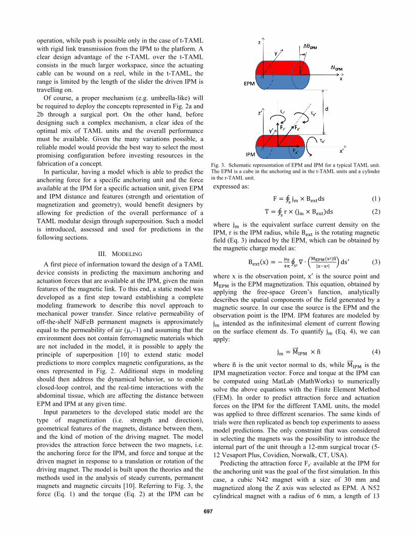
Input parameters to the developed static model are the type of magnetization (i.e. strength and direction), geometrical features of the magnets, distance between them, and the kind of motion of the driving magnet. The model provides the attraction force between the two magnets, i.e. the anchoring force for the IPM, and force and torque at the driven magnet in response to a translation or rotation of the driving magnet. The model is built upon the theories and the methods used in the analysis of steady currents, permanent magnets and magnetic circuits [10]. Referring to Fig. 3, the force (Eq. 1) and the torque (Eq. 2) at the IPM can be
expressed as:
F = ∮ jm × Bextds s (1)
T = ∮ r × (jm × Bext)ds s (2)
where jm is the equivalent surface current density on the IPM, r is the IPM radius, while Bext is the rotating magnetic field (Eq. 3) induced by the EPM, which can be obtained by the magnetic charge model as:
Bext(x) = − µ04π ∮ ∇ ∙ �MEPM(x′)n�
|x−x′| � s′ ds′ (3)
where x is the observation point, x′ is the source point and MEPM is the EPM magnetization. This equation, obtained by applying the free-space Green’s function, analytically describes the spatial components of the field generated by a magnetic source. In our case the source is the EPM and the observation point is the IPM. IPM features are modeled by jm intended as the infinitesimal element of current flowing on the surface element ds. To quantify jm (Eq. 4), we can apply:
jm = M���⃗ IPM × n� (4)
where n� is the unit vector normal to ds, while M���⃗ IPM is the IPM magnetization vector. Force and torque at the IPM can be computed using MatLab (MathWorks) to numerically solve the above equations with the Finite Element Method (FEM). In order to predict attraction force and actuation forces on the IPM for the different TAML units, the model was applied to three different scenarios. The same kinds of trials were then replicated as bench top experiments to assess model predictions. The only constraint that was considered in selecting the magnets was the possibility to introduce the internal part of the unit through a 12-mm surgical trocar (5-12 Vesaport Plus, Covidien, Norwalk, CT, USA).
Predicting the attraction force Fz’ available at the IPM for the anchoring unit was the goal of the first simulation. In this case, a cubic N42 magnet with a size of 30 mm and magnetized along the Z axis was selected as EPM. A N52 cylindrical magnet with a radius of 6 mm, a length of 13
Fig. 3. Schematic representation of EPM and IPM for a typical TAML unit. The EPM is a cube in the anchoring and in the t-TAML units and a cylinder in the r-TAML unit.
697
mm, with the main axis laying on X’ and magnetized along Z’ was used as IPM. EPM and IPM were separated by a distance, d, of 30mm. This distance corresponds to the average thickness of the abdominal wall upon insufflation [11]. The static model provided an estimation for Fz’, being all the other components of force and torque on the IPM equal to zero.
The main objective for the second test was to quantify the horizontal force Fx’ available at the IPM for the t-TAML unit. The same EPM and IPM described for the anchoring force trial, still spaced by 30 mm, were used. The EPM was moved along the X axis in steps of ∆𝑙𝐸𝑃𝑀=1 mm, starting from a position where both EPM and IPM centers were laying on the same coordinate on the X axis, until reaching a 100 mm final displacement. The static model provided an estimation of the three components of force and torque acting on the IPM at each step.
The last test was designed to estimate the x’ component of the torque, 𝜏𝑥′, at the IPM for a r-TAML unit. In this case, a N42 cylindrical driving magnet with a radius of 9.5 mm, a length of 19 mm, with its main axis laying on X and magnetized along Z was selected as EPM. The same IPM and EPM/IPM distance used for the previous simulations were also adopted in this case. The EPM was rotated about the X axis in steps of ∆𝜃𝐸𝑃𝑀=0.5°, from 0° to 180° and the three components of force and torque at the IPM were predicted for each step.
It is worth mentioning that all the cylindrical magnets assumed as IPM were modeled with a coaxial hollow cylindrical space of 1.5-mm radius to host a shaft for guidance in their final design. Similarly, the EPM used in the r-TAML simulation was modeled with a 3-mm radius coaxial cylinder hole.
The used meshing consisted of about 10,000 elements with a maximum element size fixed to 1/26 of the maximum geometric feature.
IV. EXPERIMENTAL ASSESSMENT A first step in assessing the model was to verify the
predicted magnetic field for a single magnet alone. Magnets having the same features as the ones modeled were acquired from K&J Magnetics, USA. A magnetometer (Kosvaha 5, Wuntronic GmbH, Germany) was used to measure the field surrounding each magnet at a distance of ±30 mm on the Z axis and the data were compared with the model. The maximum error between the model and the experimental data was 0.14 mT on a full range going from -18 mT to 18mT. This translates to a 0.4 % error when compared to a single-magnet model prediction.
The simulations described in the previous section were then validated by three specific bench top experiments, each replicating the EPM/IPM modeled interaction. Force data was acquired using a 6-axis load cell (NANO 17, ATI, USA). During the design of the bench-top experiments particular care was given to preventing interferences to the EPM/IPM magnetic coupling from ferromagnetic materials.
Therefore, components that may cause interferences with the magnetic field were placed far enough from EPM/IPM to have a negligible effect.
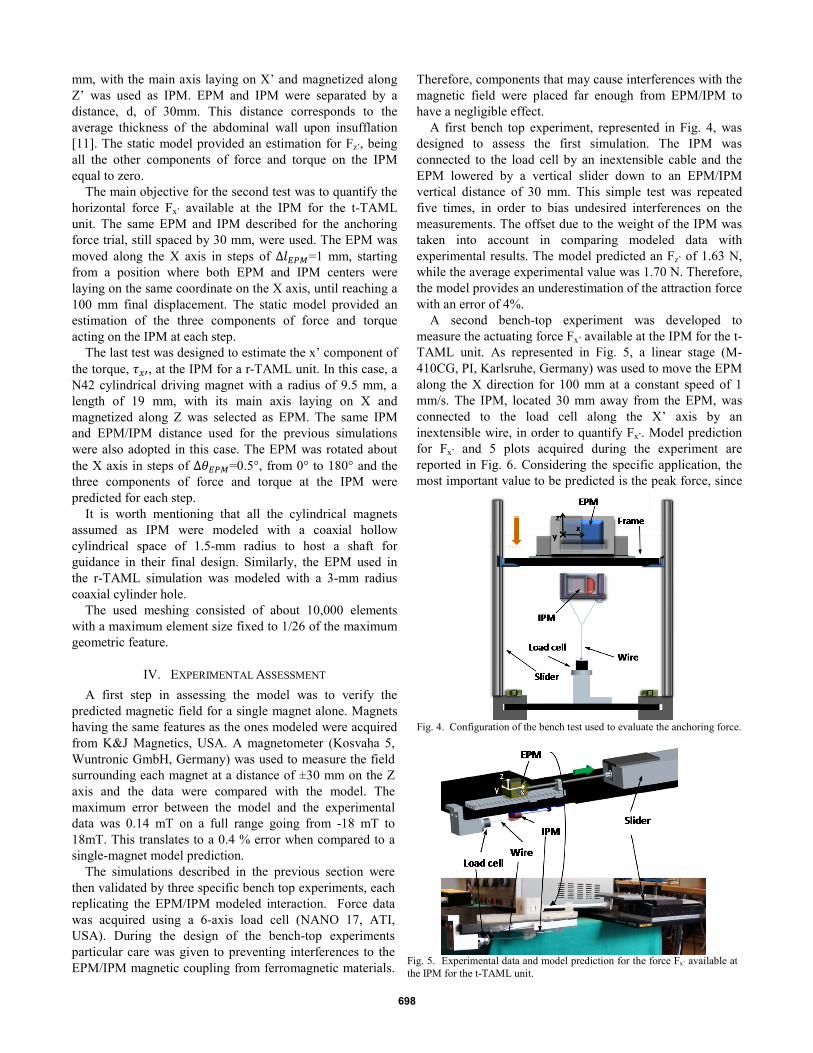
A first bench top experiment, represented in Fig. 4, was designed to assess the first simulation. The IPM was connected to the load cell by an inextensible cable and the EPM lowered by a vertical slider down to an EPM/IPM vertical distance of 30 mm. This simple test was repeated five times, in order to bias undesired interferences on the measurements. The offset due to the weight of the IPM was taken into account in comparing modeled data with experimental results. The model predicted an Fz’ of 1.63 N, while the average experimental value was 1.70 N. Therefore, the model provides an underestimation of the attraction force with an error of 4%.
A second bench-top experiment was developed to measure the actuating force Fx’ available at the IPM for the t-TAML unit. As represented in Fig. 5, a linear stage (M-410CG, PI, Karlsruhe, Germany) was used to move the EPM along the X direction for 100 mm at a constant speed of 1 mm/s. The IPM, located 30 mm away from the EPM, was connected to the load cell along the X’ axis by an inextensible wire, in order to quantify Fx’. Model prediction for Fx’ and 5 plots acquired during the experiment are reported in Fig. 6. Considering the specific application, the most important value to be predicted is the peak force, since
Fig. 4. Configuration of the bench test used to evaluate the anchoring force.
Fig. 5. Experimental data and model prediction for the force Fx’ available at the IPM for the t-TAML unit.
698
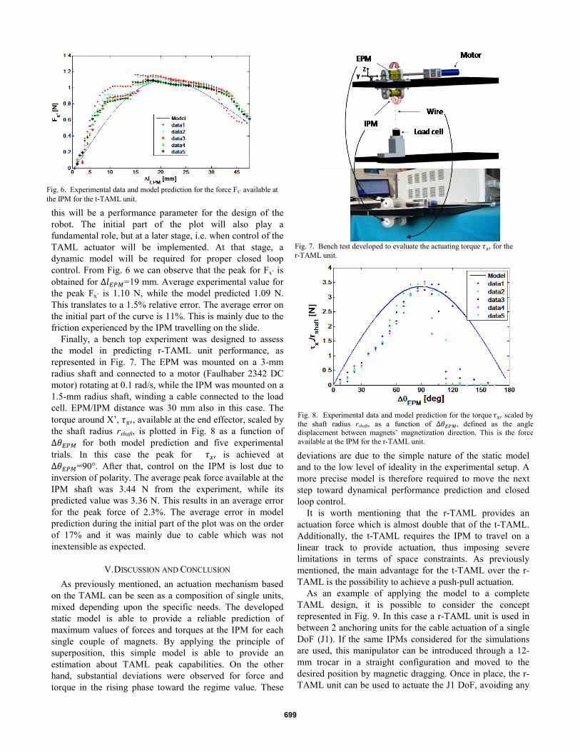
this will be a performance parameter for the design of the robot. The initial part of the plot will also play a fundamental role, but at a later stage, i.e. when control of the TAML actuator will be implemented. At that stage, a dynamic model will be required for proper closed loop control. From Fig. 6 we can observe that the peak for Fx’ is obtained for ∆𝑙𝐸𝑃𝑀=19 mm. Average experimental value for the peak Fx’ is 1.10 N, while the model predicted 1.09 N. This translates to a 1.5% relative error. The average error on the initial part of the curve is 11%. This is mainly due to the friction experienced by the IPM travelling on the slide.
Finally, a bench top experiment was designed to assess the model in predicting r-TAML unit performance, as represented in Fig. 7. The EPM was mounted on a 3-mm radius shaft and connected to a motor (Faulhaber 2342 DC motor) rotating at 0.1 rad/s, while the IPM was mounted on a 1.5-mm radius shaft, winding a cable connected to the load cell. EPM/IPM distance was 30 mm also in this case. The torque around X’, 𝜏𝑥′, available at the end effector, scaled by the shaft radius rshaft, is plotted in Fig. 8 as a function of ∆𝜃𝐸𝑃𝑀 for both model prediction and five experimental trials. In this case the peak for 𝜏𝑥′ is achieved at ∆𝜃𝐸𝑃𝑀=90°. After that, control on the IPM is lost due to inversion of polarity. The average peak force available at the IPM shaft was 3.44 N from the experiment, while its predicted value was 3.36 N. This results in an average error for the peak force of 2.3%. The average error in model prediction during the initial part of the plot was on the order of 17% and it was mainly due to cable which was not inextensible as expected.
V. DISCUSSION AND CONCLUSION As previously mentioned, an actuation mechanism based
on the TAML can be seen as a composition of single units, mixed depending upon the specific needs. The developed static model is able to provide a reliable prediction of maximum values of forces and torques at the IPM for each single couple of magnets. By applying the principle of superposition, this simple model is able to provide an estimation about TAML peak capabilities. On the other hand, substantial deviations were observed for force and torque in the rising phase toward the regime value. These
deviations are due to the simple nature of the static model and to the low level of ideality in the experimental setup. A more precise model is therefore required to move the next step toward dynamical performance prediction and closed loop control.
It is worth mentioning that the r-TAML provides an actuation force which is almost double that of the t-TAML. Additionally, the t-TAML requires the IPM to travel on a linear track to provide actuation, thus imposing severe limitations in terms of space constraints. As previously mentioned, the main advantage for the t-TAML over the r-TAML is the possibility to achieve a push-pull actuation.
As an example of applying the model to a complete TAML design, it is possible to consider the concept represented in Fig. 9. In this case a r-TAML unit is used in between 2 anchoring units for the cable actuation of a single DoF (J1). If the same IPMs considered for the simulations are used, this manipulator can be introduced through a 12-mm trocar in a straight configuration and moved to the desired position by magnetic dragging. Once in place, the r-TAML unit can be used to actuate the J1 DoF, avoiding any
Fig. 6. Experimental data and model prediction for the force Fx’ available at the IPM for the t-TAML unit.
Fig. 7. Bench test developed to evaluate the actuating torque 𝜏𝑥′ for the r-TAML unit.
Fig. 8. Experimental data and model prediction for the torque 𝜏𝑥′ scaled by the shaft radius rshaft, as a function of ∆𝜃𝐸𝑃𝑀, defined as the angle displacement between magnets’ magnetization direction. This is the force available at the IPM for the r-TAML unit.
699

manual motion of the external magnets. Assuming for each unit the same magnetic features used for simulations and bench top assessment and an abdominal tissue thickness of 30 mm, an anchoring force of 3.8 N and an actuating force of 2.9 N can be achieved. These values are derived by applying the superposition of the models of each single unit in a combined simulation. It is interesting to note that the total anchoring force is about the sum of the Fz’ contributions coming from the two anchoring units (i.e. 1.7 N each) and a 0.4 N contribution coming from the actuation unit. Concerning the actuation force, the value expected from a single r-TAML unit (i.e. 3.44 N) is reduced by the presence of the two anchoring units. Despite being below the 5 N usually considered as the maximum force exerted on the tip of a surgical instrument [12], these results represent an encouraging first step towards the design of a more optimized TAML solution.
Concerning safety, a recent study [13] reported that abdominal wall tolerated a maximum pressure of 7.78 psi even when compressed across a distance of 0.9 cm, thus supporting the further clinical development of the proposed approach.
In addition to estimates of force and torque available at the IPM, the developed model can be used in a “backward” mode, where the input are the desired force and torque value at the IPM, IPM features and EPM/IPM distance, while the output are EPM features. This “backward” mode can be useful for estimating the feasibility of applying the TAML concept to obese patients. For example, the same performance for the design represented in Fig. 9 can be achieved by using EPMs 6 times larger in lateral dimensions in a case where the abdominal tissue thickness is increased to 15 cm. Of course, different kinds of motions for the driving magnet can be devised, resulting in different and, possibly, better performances. Next steps will consist of developing a dynamical model, accounting for inertia, tissue interaction and time variant magnetic effects for each TAML unit to be used in closed loop control of a robotic device.
While a complete bimanual platform for LESS surgical robotics may be considered as the long-term goal of this work, to be pursued by more focused research efforts once the TAML feasibility is assessed, any progress achieved in TAML design and modeling may have an impact on simpler surgical and endoscopic tools, such as magnetic endoscopes or tissue retractors.
ACKNOWLEDGMENT The authors wish to thank N. Funaro, C. Filippeschi and
G. Favati for prototypes manufacturing and B. Smith for his invaluable support in proofreading the paper.
REFERENCES [1] Intuitive Surgical website, http://www.intuitivesurgical.com. [2] G. Haber, M. White, R. Autorino, P. Escobar, M. Kroh, S.
Chalikonda, R. Khanna, S. Forest, B. Yang, F. Altunrende, R. Stein, J. Kaouk, “Novel Robotic da Vinci Instruments for Laparoendoscopic Single-site Surgery”, Urology, 2010; Vol. 76, pp. 1279-1282.
[3] J. Ding, K. Xu, R. Goldman, P. Allen, D. Fowler, N. Simaan, “Design, Simulation and Evaluation of Kinematic Alternatives for Insertable Robotic Effectors Platforms in Single Port Access Surgery”, in Proc. of IEEE International Conference on Robotics and Automation (ICRA) 2010, Anchorage AK, pp. 1053-1058.
[4] A. Lehman, N. Wood, S. Farritor, M. Goede, D. Oleynikov, “Dexterous miniature robot for advanced minimally invasive surgery”, Surgical Endoscopy, 2010; Vol. 25, pp. 119-123.
[5] M. Piccigallo, U. Scarfogliero, C. Quaglia, G. Petroni, P. Valdastri, A. Menciassi, P. Dario, “Design of a novel bimanual robotic system for single-port laparoscopy”, IEEE/ASME Transaction on Mechatronics, 2010; Vol. 15, pp. 871-878.
[6] S. Park, R. Bergs, R. Eberhart, L. Baker, R. Fernandez, J. Cadeddu, “Trocar-less instrumentation for laparoscopy magnetic positioning of intra-abdominal camera and retractor”, Annals of Surgery, 2007; Vol. 245, pp. 379–384.
[7] A. Lehman, J. Dumpert, N. Wood, L. Redden, A. Visty, S. Farritor, B. Varnell, D. Oleynikov, “Natural orifice cholecystectomy using a miniature robot”, Surgical Endoscopy, 2009; Vol. 23, pp. 260-266.
[8] R. A. Joseph, N. A. Salas, M. A. Donovan, P. R. Reardon, B. L. Bass, B. J. Dunkin, ”Single-site laparoscopic (SSL) cholecystectomy in human cadavers using a novel percutaneous instrument platform and a magnetic anchoring and guidance system (MAGS): reestablishing the ‘‘critical view’’”, Surgical Endoscopy, 2012; Vol. 26, pp. 149–153.
[9] M. Simi, G. Sardi, P. Valdastri, A. Menciassi, P. Dario, “Magnetic Levitation Camera Robot for Endoscopic Surgery”, in Proc. of IEEE International Conference on Robotics and Automation (ICRA) 2011, Shanghai, China, pp. 5279-5284.
[10] E. P. Furlani, “Permanent Magnet and Electromechanical Devices”, A. Press, Ed., 2001.
[11] C. Song, A. Alijani, T. Frank, G. B. Hanna, A. Cuschieri, “Mechanical properties of the human abdominal wall measured in vivo during insufflation for laparoscopic surgery”, Surgical Endoscopy, 2006; Vol. 20, pp. 987-990.
[12] C. Richards, J. Rosen, B. Hannaford, C. Pellegrini, M. Sinanan, “Skills evaluation in minimally invasive surgery using force/torque signatures”, Surgical Endoscopy, 2000; Vol. 14, pp. 791–798.
[13] Sara L. Best, Wareef Kabbani, Daniel J. Scott, Richard Bergs, Heather Beardsley, Raul Fernandez, Lauren B. Mashaud, and Jeffrey A. Cadeddu, “Magnetic Anchoring and Guidance System Instrumentation for Laparo-endoscopic Single-site Surgery/Natural Orifice Transluminal Endoscopic Surgery: Lack of Histologic Damage After Prolonged Magnetic Coupling Across the Abdominal Wall”, Urology, 2011, Vol 77, pp. 243-247
Fig. 9. A possible design implementation combining 2 anchoring units and one r-TAML to operate a single DoF.
700