Trane CoolSense™ System Design
76
Trane CoolSense™ System Design Application Guide September 2020 DOAS-APG001A-EN SAFETY WARNING Only qualified personnel should install and service the equipment. The installation, starting up, and servicing of heating, ventilating, and air-conditioning equipment can be hazardous and requires specific knowledge and training. Improperly installed, adjusted or altered equipment by an unqualified person could result in death or serious injury. When working on the equipment, observe all precautions in the literature and on the tags, stickers, and labels that are attached to the equipment.
Transcript of Trane CoolSense™ System Design

Trane CoolSense™ System DesignApplication Guide
September 2020 DOAS-APG001A-EN
SAFETY WARNINGOnly qualified personnel should install and service the equipment. The installation, starting up, and servicing of heating, ventilating, and air-conditioning equipment can be hazardous and requires specific knowledge and training. Improperly installed, adjusted or altered equipment by an unqualified person could result in death or serious injury. When working on the equipment, observe all precautions in the literature and on the tags, stickers, and labels that are attached to the equipment.


© 2020 Trane. All Rights Reserved. Trane CoolSense™ System Design DOAS-APG001A-EN
Trane CoolSense™ System Design
Trane, in proposing these system design and application concepts, assumes no responsibility for the performance or desirability of any resulting system design. Design of the HVAC system is the prerogative and responsibility of the engineering professional.
Trademarks
Trane, the Trane logo, CoolSense, VariTrane, TRACER, CDQ, and TAP are trademarks of Trane in the United States and other countries. All trademarks referenced in this document are the trademarks of their respective owners.

iii Trane CoolSense™ System Design DOAS-APG001A-EN
Table of Contents
Overview of the Trane CoolSense™ System . . . . . . . . . . . . . . . . . . . 1Components of the system . . . . . . . . . . . . . . . . . . . . . . . . . . . . . . . . . . . . . . . 1
Advantages and drawbacks of the system . . . . . . . . . . . . . . . . . . . . . . . . . . . 3
Control of the chilled-water sensible-cooling terminal unit . . . . . . . 5Occupied mode: cooling or heating . . . . . . . . . . . . . . . . . . . . . . . . . . . . . . . . 5
Unoccupied mode: cooling, heating, or dehumidification . . . . . . . . . . . . . . 9
Demand-controlled ventilation . . . . . . . . . . . . . . . . . . . . . . . . . . . . . . . . . . . 11
Active humidity control . . . . . . . . . . . . . . . . . . . . . . . . . . . . . . . . . . . . . . . . . 13
Condensate avoidance . . . . . . . . . . . . . . . . . . . . . . . . . . . . . . . . . . . . . . . . . . 16
Condensate detection . . . . . . . . . . . . . . . . . . . . . . . . . . . . . . . . . . . . . . . . . . . 16
Three levels of protection against condensation . . . . . . . . . . . . . . . . . . . . . 17
CoolSense system-level control coordination . . . . . . . . . . . . . . . . . 18Occupied mode . . . . . . . . . . . . . . . . . . . . . . . . . . . . . . . . . . . . . . . . . . . . . . . . 18
Unoccupied mode . . . . . . . . . . . . . . . . . . . . . . . . . . . . . . . . . . . . . . . . . . . . . . 19
Morning warm-up or cool-down mode . . . . . . . . . . . . . . . . . . . . . . . . . . . . . 20
Humidity pull-down mode . . . . . . . . . . . . . . . . . . . . . . . . . . . . . . . . . . . . . . . 21
Determining DOAS supply-air dew point and airflow . . . . . . . . . . . 22DOAS airflow versus supply-air dew point . . . . . . . . . . . . . . . . . . . . . . . . . . 25
Sizing the DOAS airflow . . . . . . . . . . . . . . . . . . . . . . . . . . . . . . . . . . . . . . . . . . 6
Selecting Trane chilled-water sensible-cooling terminal units . . . . 28Selecting terminal units in Trane® Select Assist™ . . . . . . . . . . . . . . . . . . . 29
Laying out terminal unit controls in Trane® Design Assist . . . . . . . . . . . . . 35
Dedicated OA unit configurations . . . . . . . . . . . . . . . . . . . . . . . . . . 37Packaged DX versus chilled-water AHU . . . . . . . . . . . . . . . . . . . . . . . . . . . . 37
Trane Horizon™ packaged DX dedicated OA units . . . . . . . . . . . . . . . . . . . 37
Chilled-water AHU configurations . . . . . . . . . . . . . . . . . . . . . . . . . . . . . . . . . 38
Selecting DOAS air-handling units in Trane Select Assist . . . . . . . . . . . . . 42
Laying out DOAS air-handling unit controls in Trane Design Assist . . . . . 43

DOAS-APG001A-EN Trane CoolSense™ System Design iv
Chiller plant configurations . . . . . . . . . . . . . . . . . . . . . . . . . . . . . . . 45Single-temperature chiller plant and DX dedicated OA unit(s) . . . . . . . . . . 45
Dual-temperature chiller plant with a single chiller . . . . . . . . . . . . . . . . . . . 46
Dual-temperature chiller plant with two chillers . . . . . . . . . . . . . . . . . . . . . 49
Dual-temperature chiller plant with more than two chillers . . . . . . . . . . . . 52
Water economizing 54
Code compliance . . . . . . . . . . . . . . . . . . . . . . . . . . . . . . . . . . . . . . . 56Is a filter required in the sensible-cooling terminal unit? . . . . . . . . . . . . . . 56
Is an economizer required? . . . . . . . . . . . . . . . . . . . . . . . . . . . . . . . . . . . . . . 56
How does the fan power limit apply? . . . . . . . . . . . . . . . . . . . . . . . . . . . . . . 57
How does the limit on simultaneous cooling and heating apply? . . . . . . . 58
Acoustics . . . . . . . . . . . . . . . . . . . . . . . . . . . . . . . . . . . . . . . . . . . . . 60Example: Open plan office space . . . . . . . . . . . . . . . . . . . . . . . . . . . . . . . . . . 61
Example: K-12 classroom . . . . . . . . . . . . . . . . . . . . . . . . . . . . . . . . . . . . . . . . 65

1 Trane CoolSense™ System Design DOAS-APG001A-EN
Overview of the Trane CoolSense™ System
Overview of the Trane CoolSense™ System
This section overviews the primary components of a typical Trane CoolSense™ System, and discusses its high-level advantages and drawbacks.
Components of the system
In a typical Trane CoolSense system, each zone has a dedicated terminal unit that provides cooling or heating to maintain the desired temperature in that zone. All the outdoor air required for ventilation is conditioned by a dedicated outdoor-air (OA) unit. This unit filters, cools, dehumidifies, and heats the outdoor air before distributing it through a duct system to a terminal unit serving each zone (Figure 1).
Figure 1. Trane CoolSense system
Each terminal unit, which is typically installed in the ceiling plenum above the space, is equipped with a fan and a chilled-water coil mounted at the inlet from the ceiling plenum. The conditioned outdoor air (CA) from the dedicated OA unit enters each terminal unit through a flow-measuring damper (same components used in VariTrane™ VAV terminals), where it then mixes with recirculated air (RA) from the zone that has passed through the cooling coil (Figure 2). Finally, the terminal fan delivers this mixed supply air (SA) to the zone through downstream ductwork and diffusers. The fan is equipped with an electronically-commutated motor (ECM), which allows the fan speed, and therefore the supply airflow, to be varied as the zone load changes. For those zones that may require heating, a separate hot-water coil or electric heater may be included in the terminal unit.

DOAS-APG001A-EN Trane CoolSense™ System Design 2
Overview of the Trane CoolSense™ System
Figure 2. Trane chilled-water sensible-cooling terminal unit
All the terminal unit cooling coils are connected to a chilled-water distribution loop, which also includes one or more water chillers and water-circulating pumps (see “Chiller plant configurations,” p. 45). The chilled water supplied to the terminal unit cooling coils is controlled to a temperature—typically between 56°F and 58°F—that is above the dew point temperature in the zone, so that the terminal unit cooling coils operate dry and provide only sensible cooling (no dehumidification, so no condensation).
To enable the terminal units to operate dry, the dedicated OA unit must dehumidify the outdoor air to a dew point that is dry enough to offset the entire zone latent load (due to people and infiltration, for example) and maintain the zone dew point at or below a defined threshold—typically 55°F (see “DOAS supply-air dew point and airflow,”p. 22 ). The dedicated OA unit might be a standalone, air-cooled, direct-expansion (DX) unit, or it might be an air-handling unit connected to the chilled-water distribution loop (see “Dedicated OA unit configurations,” p. 37).
Zone-level heating is typically provided by a separate hot-water coil or electric heater in the terminal unit. When hot water is used, all the terminal unit heating coils are connected to a hot-water distribution loop, which also includes one or more boilers and water-circulating pumps.
Each terminal unit can be equipped with a Tracer® UC™400 controller that regulates cooling, heating, dehumidification, and ventilation for the zone it serves (see “Control of the chilled-water sensible-cooling terminal unit,” p. 5) The Tracer® SC+ system-level controller can then be used to coordinate operation of the terminal units, water chillers, boilers, pumps, and dedicated outdoor-air units, so they operate together as an efficient system (see “CoolSense system-level control coordination,” p. 18).

3 Trane CoolSense™ System Design DOAS-APG001A-EN
Overview of the Trane CoolSense™ System
Advantages and drawbacks of the system
As buildings are designed for lower energy use, the resulting reduction in sensible cooling loads presents an economically feasible opportunity for systems that use zone-level, sensible-only cooling equipment. Reasons for using a Trane CoolSense system include:
Efficiency
• Variable-speed fan control in both the terminal units and dedicated OA unit.
• Zone sensible cooling is provided with warmer chilled water—typically 56°F to 58°F.
• Each terminal unit is equipped with a flow-measuring damper, making it easy to implement demand-controlled ventilation.
Comfort
• Each terminal unit is controlled by a zone temperature sensor, and contains a cooling coil and (optionally) either a hot-water coil or electric heater, allowing each zone to receive either cooling or heating as needed.
• Dehumidification is provided by the centralized, dedicated OA unit; and, when equipped with a humidity sensor, the terminal unit actively adjusts dehumidified airflow from the dedicated OA unit to control space humidity.
Flexibility and space required
• The dedicated OA unit and its associated ductwork are typically sized for only the minimum ventilation airflow required, in turn requiring less ceiling plenum height and allowing for more usable space inside the building.
• Re-configuring a zone often requires moving only the downstream flex duct and supply-air diffusers; the terminal units and water piping may not need to be moved.
• The sensible-cooling terminal units can be equipped with either a hot-water coil or electric heater, if necessary. Electric heat offers a lower installed cost option, avoiding the need to install a hot-water distribution system.
Maintenance
• No condensation occurs at the zone-level terminal units, meaning no drain pans to clean and no condensate drain traps and piping to install and maintain.
• Since the cooling coil in each terminal unit operates dry, no filter is required upstream.
A comparison of the annual energy used by the CoolSense system, compared to other systems, is included in the Trane “CoolSense Integrated Outdoor Air” system catalog, APP-PRC004*-EN.

DOAS-APG001A-EN Trane CoolSense™ System Design 4
Overview of the Trane CoolSense™ System
Following are some of the typical challenges (or drawbacks) of using a chilled-water sensible-cooling system, along with some potential ways to address those challenges:
Equipment is located in or near the occupied spaces
• The terminal units are typically located near the occupied space. This requires the use of ceiling space throughout the building, and achieving acceptable noise levels in the space needs to be considered during system design.
Distributed maintenance
• Because the terminal units are distributed throughout the building, maintenance must be performed in the ceiling in or near the occupied spaces. This can be disruptive to occupants, or it may lead to neglecting preventative maintenance.
• Proper maintenance of the terminal units requires that they be located in accessible areas. In a new building, this requires close coordination with the architect. Additionally, selecting units that are designed for easy access increases the chance that the equipment will be properly maintained.
• Since each terminal unit contains a chilled-water coil (and possibly a hot-water coil), piping and control valves must be installed to distribute water to every zone of the building. This increases the risk of water leaks, and in climates that experience sub-freezing weather there may be the added concern to prevent freezing water in the pipes.

5 Trane CoolSense™ System Design DOAS-APG001A-EN
Control of the chilled-water sensible-cooling terminal unit
Control of the chilled-water
sensible-cooling terminal unit
This section contains a detailed description of the control sequences for Trane chilled-water sensible-cooling terminal units, which are pre-engineered into the Tracer® UC™400 controller. This controller operates the variable-speed terminal fan, the ventilation air damper, the modulating chilled-water valve, and the hot-water valve or electric heater (if equipped). In addition, this controller can be configured for demand-controlled ventilation (DCV), active humidity control, and condensate avoidance or detection.
Occupied mode: cooling or heating
Figure 3 and Figure 4 depict the control sequence for a chilled-water sensible-cooling terminal unit during Occupied mode. The X axis is the sensible load in the zone, with design heating load on the far left and design cooling load on the far right.
Deadband. When the zone temperature is satisfied (in the deadband between its Occupied Heating and Cooling setpoints), the Tracer® UC™400 controller operates the fan at its Minimum Fan Airflow setpoint (20 percent in this example), with both the chilled-water valve and hot-water valve closed (or electric heater off).
The ventilation air damper is controlled to the minimum outdoor airflow setpoint. If DCV is being used, this setpoint will vary between the design outdoor airflow for the zone (OAdesign) and the minimum outdoor airflow allowed during DCV (OADCVmin), which is why control of the ventilation damper is depicted as a range, rather than a single line (see “Demand-controlled ventilation,” p. 11).
Note: If DCV is used, the Minimum Fan Airflow setpoint can also vary so that fan airflow always exceeds the current outdoor airflow.
Cooling. When the zone temperature rises to its Occupied Cooling setpoint, the Tracer® UC™400 controller maintains the zone temperature at this Occupied Cooling setpoint by modulating both the terminal fan speed and chilled-water valve, while the hot-water valve or electric heat remain off (if equipped):
• First stage: The controller first modulates the chilled-water valve (blue line) further open to maintain zone temperature at its Occupied Cooling setpoint, while the fan (green line) remains operating at its Minimum Fan Airflow setpoint. The ventilation air damper (purple band) controls to its minimum outdoor airflow setpoint.
• Second stage: When the requested cooling capacity has increased to the point where the chilled-water valve (blue line) is fully (100 percent) open, the controller increases the fan speed (green line) to maintain zone temperature at its Occupied Cooling setpoint, while the chilled-water valve remains fully open. The ventilation air damper (purple band) controls to its minimum outdoor airflow setpoint.

DOAS-APG001A-EN Trane CoolSense™ System Design 6
Control of the chilled-water sensible-cooling terminal unit
• Third stage (“boost” mode): If the fan (green line) reaches its Maximum (100 percent) Cooling Fan Airflow setpoint, but the unit requires even more cooling capacity, the controller can modulate the ventilation air damper (purple line) further open (increasing the flow rate of cool, dehumidified air from the DOAS) to maintain zone temperature at its Occupied Cooling setpoint, while the chilled-water valve remains fully (100 percent) open and the fan operates at its Maximum (100 percent) Cooling Fan Airflow setpoint. This Maximum Ventilation Airflow (damper) setpoint is user-adjustable. This “boost” mode is not intended to be typical operation. The terminal unit should be selected to offset the design space cooling load with the fan at full speed and chilled-water valve 100 percent open. This “boost” mode is for unintended situations that the design engineer did not consider when sizing (e.g., 30 people cramming into a conference room that was designed for 20 people).
Heating. For terminal units equipped with a discharge-air temperature (DAT) sensor and modulating hot-water valve or an SCR (modulating) electric heater (Figure 3), when the zone temperature drops to its Occupied Heating setpoint, the Tracer® UC™400 controller maintains the zone temperature at this Occupied Heating setpoint by modulating both the terminal fan speed and hot-water valve (or SCR electric heater), while the chilled-water valve remains closed:
• First stage: The controller first modulates the hot-water valve (red line) further open (or increases the capacity of the SCR electric heater) to maintain zone temperature at its Occupied Heating setpoint, while the fan (green line) continues to operate at its Minimum Heating Fan Airflow setpoint. The ventilation air damper (purple band) controls to its minimum outdoor airflow setpoint.
• Second stage: When the requested heating capacity has increased to the point where the DAT (red line) reaches a user-adjustable Design DAT Limit (90°F, for example), the controller increases the fan speed (green line) to maintain zone temperature at its Occupied Heating setpoint, while the hot-water valve (or SCR electric heater) modulates to maintain the discharge air temperature at this Design DAT Limit. The ventilation air damper (purple band) controls to its minimum outdoor airflow setpoint.
• Third stage: If the requested heating capacity has increased to the point where the fan (green line) has reached its Maximum (100 percent) Heating Fan Airflow setpoint, the controller shall modulate the hot-water valve (red line) further open (or increase the capacity of the SCR electric heater) to maintain zone temperature at its Occupied Heating setpoint, while the fan continues to operate at its Maximum (100 percent) Heating Fan Airflow setpoint. While this will cause the discharge air temperature to exceed the Design DAT Limit, it will avoid temperature control complaints to the building operator. The ventilation air damper (purple band) controls to its minimum outdoor airflow setpoint.

7 Trane CoolSense™ System Design DOAS-APG001A-EN
Control of the chilled-water sensible-cooling terminal unit
Figure 3. Chilled-water sensible cooling terminal unit control with modulating heat (occupied mode)

DOAS-APG001A-EN Trane CoolSense™ System Design 8
Control of the chilled-water sensible-cooling terminal unit
Figure 4. Chilled-water sensible-cooling terminal unit control with staged heat (occupied mode)

9 Trane CoolSense™ System Design DOAS-APG001A-EN
Control of the chilled-water sensible-cooling terminal unit
For terminal units equipped with a staged electric heater (Figure 4), when the zone temperature drops to its Occupied Heating setpoint, the Tracer® UC™400 controller maintains the zone temperature at this Occupied Heating setpoint by modulating the terminal fan speed and staging the electric heater, while the chilled-water valve remains closed:
• First stage: The controller first increases the fan speed (green line), recirculating more warm air from the ceiling plenum, to maintain zone temperature at its Occupied Heating setpoint, while the electric heater (red line) remains off. The ventilation air damper (purple band) controls to its minimum outdoor airflow setpoint.
Second stage: When the requested heating capacity has increased to the point where the fan (green line) has reached its Maximum (100 percent) Heating Fan Airflow setpoint, the controller stages capacity of the electric heater to maintain zone temperature at its Occupied Heating setpoint, while the fan continues to operate at its Maximum (100 percent) Heating Fan Airflow setpoint. The ventilation air damper (purple band) controls to its minimum outdoor airflow setpoint.
Unoccupied mode: cooling, heating, or
dehumidification
Table 1 depicts the control sequence for a chilled-water sensible-cooling terminal unit during Unoccupied mode.
Table 1. Chilled-water sensible-cooling terminal unit control in unoccupied mode
zone conditions terminal fan ventilation air damper
chilled-water valve
hot-water valve
(electric heater)
deadband (off)DBTzone ≥ HeatingSetpointunoccupied andDBTzone ≤ CoolingSetpointunoccupied
off closed closed closed (off)
unoccupied heating DBTzone < HeatingSetpointunoccupied 100 percent speed closed closed 100 percent open (on)
unoccupied cooling
DBTzone > CoolingSetpointunoccupiedandUnoccupied Cooling Source= “Sensible Coil”
100 percent speed closed 100 percent open closed (off)
DBTzone > CoolingSetpointunoccupiedandUnoccupied Cooling Source= “Air Handler” 100 percent speed open closed closed (off)
DBTzone > CoolingSetpointunoccupiedandcondensate detectedorDPTzone > DewPointLimitunoccupied
100 percent speed open closed closed (off)
unoccupied dehumidification
DBTzone ≥ HeatingSetpointunoccupiedandDBTzone ≤ CoolingSetpointunoccupiedandDPTzone > DewPointLimitunoccupied
100 percent speed open closed closed (off)

DOAS-APG001A-EN Trane CoolSense™ System Design 10
Control of the chilled-water sensible-cooling terminal unit
Deadband. When the zone temperature (DBTzone) is satisfied (in the deadband between its Unoccupied Heating and Unoccupied Cooling setpoints), the Tracer® UC™400 controller turns off the fan, closes the ventilation air damper, closes the chilled-water valve, and closes the hot-water valve (or turns off the electric heater)—unless Unoccupied Dehumidification is needed (see below).
Unoccupied Heating. If the zone temperature drops below its Unoccupied Heating setpoint, the Tracer® UC™400 controller turns on the fan and operates at its Maximum Heating Fan Airflow setpoint, keeps both the ventilation air damper and chilled-water valve closed, and fully opens the hot-water valve (or activates the electric heater to 100 percent capacity), until the zone temperature rises back to 2°F above this Unoccupied Heating setpoint.
Unoccupied Cooling. When the Unoccupied Cooling Source is configured as “Sensible Coil” (in the terminal unit), if the zone temperature rises above its Unoccupied Cooling setpoint, the Tracer® UC™400 controller turns on the fan and operates at its Maximum Cooling Fan Airflow setpoint, keeps both the ventilation air damper and hot-water valve closed (or turns off the electric heater), and fully opens the chilled-water valve, until the zone temperature drops back to 2°F below this Unoccupied Cooling setpoint.
During this mode, if condensate is detected in the drip pan, or if the zone dew point (DPTzone) rises above the Unoccupied Dew Point High Limit, the controller closes the chilled-water valve and opens the ventilation air damper to its Maximum Ventilation Airflow setpoint, until condensate is no longer detected and the zone dew point drops back below its Unoccupied Dew Point Low Limit.
When the Unoccupied Cooling Source is configured as “Air Handler” (DOAS), if the zone temperature rises above its Unoccupied Cooling setpoint, the Tracer® UC™400 controller turns on the fan and operates at its Maximum Cooling Fan Airflow setpoint, opens the ventilation air damper to its Maximum Ventilation Airflow setpoint, and closes both the chilled-water valve and hot-water valve (or turns off the electric heater), until the zone temperature drops back to 2°F below this Unoccupied Cooling setpoint.
Unoccupied Dehumidification. If the zone dew point rises above its Unoccupied Dew Point High Limit while the zone temperature is satisfied (in the deadband between its Unoccupied Heating and Unoccupied Cooling setpoints), the Tracer® UC™400 controller turns on the fan and operates at its Maximum Cooling Fan Airflow setpoint, opens the ventilation air damper to its Maximum Ventilation Airflow setpoint, and closes both the chilled-water valve and hot-water valve (or turns off the electric heater), until the zone dew point drops back below its Unoccupied Dew Point Low Limit.
The Tracer® UC™400 controller includes a configuration setting to select either a) the sensible cooling coil in the terminal unit (“Sensible Coil”) or b) the dedicated OA unit (“Air Handler”) as the source for cooling in the Unoccupied Cooling mode.

11 Trane CoolSense™ System Design DOAS-APG001A-EN
Control of the chilled-water sensible-cooling terminal unit
Demand-controlled ventilation
Since the conditioned outdoor air from the dedicated OA unit is delivered to an airflow-measuring damper in each terminal unit, implementing demand-controlled ventilation (DCV) is quite straightforward.
By connecting a zone CO2 sensor to the Tracer® UC™400 controller, the DCV sequence will adjust outdoor airflow by modulating the ventilation air damper, based on the current CO2 concentration in the zone (Figure 5):
• When the measured CO2 concentration in the zone is equal to or higher than the CO2 High Limit, the controller positions the ventilation air damper to bring in the “design” outdoor airflow required for the zone.
• When the measured CO2 concentration in the zone is equal to or lower than the CO2 Low Limit, the controller positions the ventilation air damper to bring in the “DCV minimum” outdoor airflow, which is typically the building component of the required ventilation rate (Ra × Az).
• When the measured CO2 concentration in the zone is between the CO2 Low and High Limits, the controller modulates the ventilation air damper proportionally (purple line, ventilation airflow setpoint) between these two airflow setpoints.
As mentioned earlier, the ventilation damper may be opened further—up to the user-adjustable Maximum Ventilation Airflow (damper) setpoint—as part of the “boost” mode when cooling (Figure 3 and Figure 4).
Figure 5. Demand-controlled ventilation (DCV) sequence

DOAS-APG001A-EN Trane CoolSense™ System Design 12
Control of the chilled-water sensible-cooling terminal unit
Alternatively, an occupancy sensor can be used instead of a CO2 sensor. When the sensor indicates that the zone is occupied, the controller adjusts the ventilation air damper to bring in the “design” outdoor airflow required; and when the sensor indicates that the zone is not presently occupied, the controller adjusts the ventilation air damper to bring in the “DCV minimum” outdoor airflow.
Calculating ventilation airflow and CO2 setpoints for DCV sequence
Step 1) Calculate the “design” outdoor airflow (Vbz-design) for the zone at design occupancy, using the following equation from ASHRAE Standard 62.1:
Vbz = Rp × Pz + Ra × Az
Consider an example 600-ft2 (Az) conference room with a design population (Pz) of 30 people (corresponds to the “North Conference Rooms” zone in Table 9). For this type of space, Standard 62.1 requires 5 cfm/person (Rp) plus 0.06 cfm/ft2 (Ra). This equates to a “design” outdoor airflow equal to 186 cfm:
Vbz-design = (5 cfm/person × 30 people) + (0.06 cfm/ft2 × 600 ft2) = 186 cfm
Step 2) Use the same equation to calculate the “DCV minimum” outdoor airflow (Vbz-DCVmin) when no occupants (Pz = 0) are currently present in the zone. For this same example 600-ft2 (Az) conference room, this equates to a “DCV minimum” outdoor airflow equal to 36 cfm:
Vbz-DCVmin = (5 cfm/person × 0 people) + (0.06 cfm/ft2 × 600 ft2) = 36 cfm
Note: This “DCV minimum” outdoor airflow setpoint may need to be increased if the zone requires makeup air to replace air that is exhausted directly from the zone, as might be the case in a kitchen, a laboratory, an art or science classroom, or any space with a restroom connected to it. In this case, this setpoint may need to be adjusted so it is slightly above the local exhaust airflow to ensure positive building pressurization.
Step 3) Calculate the CO2 High Limit (Cspace-design) for when the zone is at design occupancy with “design” outdoor airflow (Vbz-design), using the following equation:
Cspace = COA + 1,000,000 × (MET × 0.0084 cfm/p/Met) / (Vbz / Pz)
For this example conference room, the occupant activity level (MET) is assumed to be 1.0 Met (seated, quiet) and the outdoor CO2 concentration (COA) is assumed to be 400 ppm. This equates to a CO2 High Limit of 1750 ppm:
Cspace-design = 400 ppm + 1,000,000 × (1.0 Met × 0.0084 cfm/p/Met) / (186 cfm / 30 people) = 1750 ppm
Step 4) Use the same equation to calculate CO2 Low Limit (Cspace-DCVmin) for when no occupants (Pz = 0) are currently present in the zone. This equates to a CO2 Low Limit of 400 ppm:
Cspace-DCVmin = 400 ppm + 1,000,000 × (1.0 Met × 0.0084 cfm/p/Met) / (36 cfm / 0 people) = 400 ppm
Occupant CO2 generation rate: The rate at which the occupants produce carbon dioxide varies with diet and health, as well as with the duration and intensity of phys-ical activity. According to the Standard 62.1-2010 User’s Manual (Appendix A), this CO2 generation rate averages about 0.0084 cfm/person/Met over the general adult population. Table 2 includes assumed activity levels (and corresponding Met values) for several common occupancy categories

13 Trane CoolSense™ System Design DOAS-APG001A-EN
Control of the chilled-water sensible-cooling terminal unit
Table 2. Occupant activity levels for common occupancy categories
Outdoor CO2 concentration: Unless the outdoor-air intake is located very close to an area with heavy vehicle traffic, it is common for design engineers to assume the outdoor concentration of CO2 (COA) to equal 400 ppm.
Active humidity control
In a Trane CoolSense system, the airflow delivered to the terminal unit by the dedicated OA unit is the only source of dehumidification. Therefore, when this airflow is reduced by DCV, it is also providing less dehumidification. If the only (or dominant) source of latent load in the zone is due to people, this is probably not an issue; if the people are not present to generate CO2, they are also not generating latent load.
If a humidity sensor is also installed in the space, the Tracer® UC™400 controller will dynamically calculate the ventilation airflow (damper) setpoint required for humidity control (the “ventilation airflow for dew point” purple line on the right-hand chart in Figure 6):
• When the measured dew point in the zone equals the Maximum Dew Point Limit (55°F, for example), the controller positions the ventilation air damper to bring in the “design” outdoor airflow required for the zone.
• If the measured dew point rises above this Maximum Dew Point Limit, the controller will open the ventilation damper even further, up to the user-adjustable Maximum Ventilation Airflow (damper) setpoint.
• When the measured dew point in the zone drops below this Maximum Dew Point Limit, the controller will reduce the ventilation airflow requested for humidity control.
occupancy categoryassumed occupant
activity level, Met(1)
office space seated, typing (1.1 Met)
conference room seated, quiet (1.0 Met)
break room seated, filing (1.2 Met)
reception area seated, filing (1.2 Met)
bank lobby walking about (1.7 Met)
K-12 classroom seated, filing (1.2 Met)
multi-use assembly seated, quiet (1.0 Met)
auditorium seated, quiet (1.0 Met)
library seated, typing (1.1 Met)
retail sales floor walking about (1.7 Met)
As described in Figure 3 and Figure 4, if the chilled-water valve is fully (100 percent) open and the fan speed has been increased up to its Maximum (100 percent) Cooling Fan Airflow setpoint, but the unit requires even more cooling capacity (third stage of cooling or “boost” mode), the controller can modulate the ventilation air damper open even further—up to the user-adjustable Maximum Ventilation Airflow (damper) setpoint—thereby increasing the flow rate of presumably cool air from the dedicated OA unit to maintain zone temperature at its cooling setpoint.
1 Assumed occupant activity level for listed occupancy category, using Met values from the 2017 ASHRAE Handbook–Fundamentals (Chapter 9, Table 4).

DOAS-APG001A-EN Trane CoolSense™ System Design 14
Control of the chilled-water sensible-cooling terminal unit
If a CO2 sensor (or occupancy sensor) is also installed in the space, the controller will also dynamically calculate the ventilation airflow (damper) setpoint required for DCV (the “ventilation airflow for CO2” purple line on the left-hand chart in Figure 6). Then the controller will use the higher of these two calculated airflows (“ventilation airflow for CO2” or “ventilation airflow for dew point”) to position the ventilation air damper. That is, if the dew point in the zone rises too high, the controller will modulate the ventilation damper further open, overriding DCV to provide more dehumidification.
Figure 6. DCV integrated with active humidity control
15 Trane CoolSense™ System Design DOAS-APG001A-EN
Control of the chilled-water sensible-cooling terminal unit
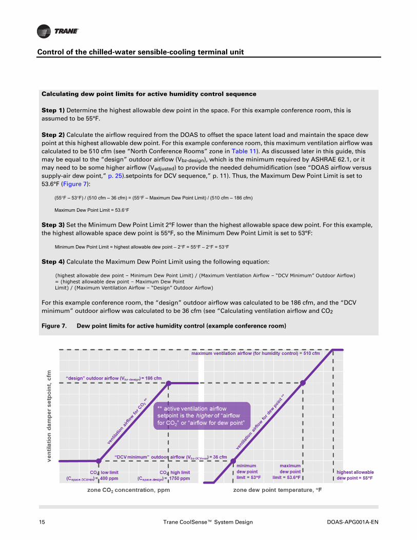
Calculating dew point limits for active humidity control sequence
Step 1) Determine the highest allowable dew point in the space. For this example conference room, this is assumed to be 55°F.
Step 2) Calculate the airflow required from the DOAS to offset the space latent load and maintain the space dew point at this highest allowable dew point. For this example conference room, this maximum ventilation airflow was calculated to be 510 cfm (see “North Conference Rooms” zone in Table 11). As discussed later in this guide, this may be equal to the “design” outdoor airflow (Vbz-design), which is the minimum required by ASHRAE 62.1, or it may need to be some higher airflow (Vadjusted) to provide the needed dehumidification (see “DOAS airflow versus supply-air dew point,” p. 25).setpoints for DCV sequence,” p. 11). Thus, the Maximum Dew Point Limit is set to 53.6°F (Figure 7):
(55°F – 53°F) / (510 cfm – 36 cfm) = (55°F – Maximum Dew Point Limit) / (510 cfm – 186 cfm)
Maximum Dew Point Limit = 53.6°F
Step 3) Set the Minimum Dew Point Limit 2°F lower than the highest allowable space dew point. For this example, the highest allowable space dew point is 55°F, so the Minimum Dew Point Limit is set to 53°F:
Minimum Dew Point Limit = highest allowable dew point – 2°F = 55°F – 2°F = 53°F
Step 4) Calculate the Maximum Dew Point Limit using the following equation:
(highest allowable dew point – Minimum Dew Point Limit) / (Maximum Ventilation Airflow – “DCV Minimum” Outdoor Airflow) = (highest allowable dew point – Maximum Dew Point Limit) / (Maximum Ventilation Airflow – “Design” Outdoor Airflow)
For this example conference room, the “design” outdoor airflow was calculated to be 186 cfm, and the “DCV minimum” outdoor airflow was calculated to be 36 cfm (see “Calculating ventilation airflow and CO2
Figure 7. Dew point limits for active humidity control (example conference room)

DOAS-APG001A-EN Trane CoolSense™ System Design 16
Control of the chilled-water sensible-cooling terminal unit
Condensate avoidance
In addition to this “active humidity control” sequence, there is a “condensate avoidance” sequence in the event that the measured dew point in the zone continues to rise too high.
If a humidity sensor is installed in the space, the Tracer® UC™400 controller will temporarily close the chilled-water valve if the measured zone dew point rises above the current entering chilled-water temperature (57°F, for example). The terminal unit fan and ventilation air damper continue to operate as normal.
With the chilled-water valve forced closed, first stage of cooling (modulating the chilled-water valve) is not available and second stage (increasing the fan speed) will provide no cooling benefit, because the recirculated air is not likely to be cooler than the space. So the proportional-integral control loop signal will reach third stage of cooling (“boost” mode) very quickly (see Figure 3 and Figure 4). This will result in the ventilation air damper modulating further open—up to the user-adjustable Maximum Ventilation Airflow (damper) setpoint—thereby increasing the flow rate of dehumidified air from the dedicated OA unit.
Once the zone dew point decreases again—to less than 5°F below the entering chilled-water temperature—the controller allows the chilled-water valve to open again and the ventilation air damper returns to its active ventilation airflow setpoint.
Note: Note: The entering chilled-water temperature can be either a) communicated from Tracer® SC+ or b) measured by an optional sensor attached to the chilled-water pipe entering the terminal unit coil.
Condensate detection
All Trane sensible-cooling terminal units are built with a drip pan located underneath the cooling coil, with a moisture sensor installed in this pan (Figure 8). If this sensor detects the presence of condensate in the drip pan, the Tracer® UC™400 controller will temporarily close the chilled-water valve, and continue operating the terminal unit fan and ventilation air damper as normal (through second and third stages of cooling, as described above).
Once condensate is no longer detected by the moisture sensor, the controller allows the chilled-water valve to open again, returning to normal operation.

17 Trane CoolSense™ System Design DOAS-APG001A-EN
Control of the chilled-water sensible-cooling terminal unit
Figure 8. Drip pan moisture sensor
Three levels of protection against
condensation
For those concerned about condensation in sensible-cooling systems, the Tracer® UC™400 controller offers three levels of protection:
1. Active humidity control: If a humidity sensor (optional) is installed in the zone, the controller will dynamically reset the current ventilation airflow setpoint based on the measured dew point in the zone.
2. Condensate avoidance: If a humidity sensor (optional) is installed in the zone, the controller will temporarily close the chilled-water valve if the measured dew point in the zone exceeds the entering chilled-water temperature.
3. Condensate detection: If the moisture sensor installed in the drip pan (standard feature in all terminal units) detects the presence of condensate in the drip pan, the controller will temporarily close the chilled-water valve.
DOAS-APG001A-EN Trane CoolSense™ System Design 18
CoolSense system-level control coordination
CoolSense system-level control
coordination
Each chilled-water sensible-cooling terminal unit is equipped with a dedicated, Tracer® UC™400 controller that responds to the cooling, heating, dehumidification, and ventilation demands of the zone it serves.
The Tracer® SC+ system-level controller is then used to determine the operating mode and coordinate operation of the terminal units, water chillers, boilers, pumps, and dedicated outdoor-air units. The primary system-level operating modes in a Trane CoolSense system are:
• Occupied mode
• Unoccupied mode
• Morning warm-up (or cool-down) mode
• Humidity pull-down mode
A time-of-day schedule in the Tracer® SC+ is used to define when the system is to operate in these various modes.
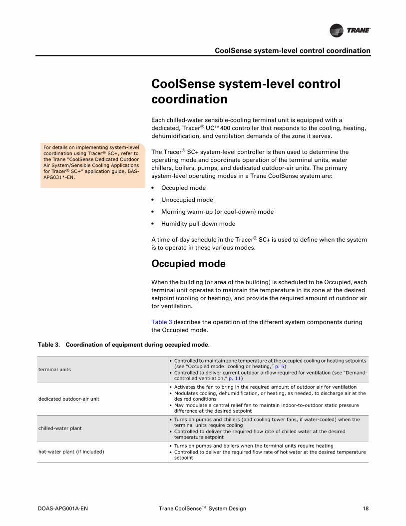
Occupied mode
When the building (or area of the building) is scheduled to be Occupied, each terminal unit operates to maintain the temperature in its zone at the desired setpoint (cooling or heating), and provide the required amount of outdoor air for ventilation.
Table 3 describes the operation of the different system components during the Occupied mode.
Table 3. Coordination of equipment during occupied mode.
For details on implementing system-level coordination using Tracer® SC+, refer to the Trane “CoolSense Dedicated Outdoor Air System/Sensible Cooling Applications for Tracer® SC+” application guide, BAS-APG031*-EN.
terminal units
• Controlled to maintain zone temperature at the occupied cooling or heating setpoints (see “Occupied mode: cooling or heating,” p. 5)
• Controlled to deliver current outdoor airflow required for ventilation (see “Demand-controlled ventilation,” p. 11)
dedicated outdoor-air unit
• Activates the fan to bring in the required amount of outdoor air for ventilation• Modulates cooling, dehumidification, or heating, as needed, to discharge air at the
desired conditions• May modulate a central relief fan to maintain indoor-to-outdoor static pressure
difference at the desired setpoint
chilled-water plant
• Turns on pumps and chillers (and cooling tower fans, if water-cooled) when the terminal units require cooling
• Controlled to deliver the required flow rate of chilled water at the desired temperature setpoint
hot-water plant (if included)• Turns on pumps and boilers when the terminal units require heating• Controlled to deliver the required flow rate of hot water at the desired temperature
setpoint

19 Trane CoolSense™ System Design DOAS-APG001A-EN
CoolSense system-level control coordination
Unoccupied mode
When the building (or area of the building) is scheduled to be Unoccupied, the system is typically shut off and the dry-bulb temperature in each zone is typically allowed to drift away (cooler or warmer) from the occupied setpoints. But if a zone gets too warm or too cold, the system may turn back on temporarily and operate in Unoccupied Cooling or Heating mode. In addition, if the zone dew point rises too high, the system may turn back on temporarily and operate in Unoccupied Dehumidification mode.
Table 4, Table 5, and Table 6 describe the operation of the different system components during the various Unoccupied modes
Table 4. Coordination of equipment during unoccupied mode (off).
Table 5. Coordination of equipment during Unoccupied Cooling or Heating mode
terminal units
• Fan is turned off• Chilled-water valve is closed• Hot-water valve is closed (or electric heater is off)• Ventilation air damper is closed
dedicated outdoor-air unit• Fan is turned off• Cooling, dehumidification, and heating are disabled• Central relief fan is turned off
chilled-water plant • Pumps and chillers (and cooling tower fans, if water-cooled) are turned off
hot-water plant (if included) • Pumps and boilers are turned off
terminal units• Controlled to cool the zone back down to the Unoccupied Cooling setpoint, or to heat
the zone back up to the Unoccupied Heating setpoint, and then turns off (see “Unoccupied mode: cooling, heating, or dehumidification,” p. 9)
dedicated outdoor-air unit
If Unoccupied Cooling Source = Sensible Coil (terminal unit):• Fan is turned off• Cooling, dehumidification, and heating are disabled• Central relief fan is turned off
If Unoccupied Cooling Source = Air Handler (DOAS):• Activates the fan• Modulates dehumidification and/or heating, as needed, to discharge air at the
desired conditions• Typically opens a recirculating air damper (and closes the outdoor-air damper with
central relief fan turned off)
chilled-water plant
• Turns on pumps and chillers (and cooling tower fans, if water-cooled) if the dedicated OA unit or terminal units require cooling
• Controlled to deliver the required flow rate of chilled water at the desired temperature setpoint
hot-water plant (if included)• Turns on pumps and boilers if the terminal units require heating• Controlled to deliver the required flow rate of hot water at the desired temperature
setpoint

DOAS-APG001A-EN Trane CoolSense™ System Design 20
CoolSense system-level control coordination
Table 6. Coordination of equipment during Unoccupied Dehumidification mode
Morning warm-up or cool-down mode
As mentioned previously, the temperature inside a building is typically allowed to drift when unoccupied, usually for the purpose of saving energy. This generally requires the HVAC system to start prior to occupancy, and operate long enough for the temperature inside the building to reach the desired occupied setpoint by the time people are expected to occupy the building. This Morning Warm-Up or Cool-Down mode typically occurs as a transition from the Unoccupied mode to the Occupied mode.
Table 7 describes the operation of the different system components during the Morning Warm-Up or Cool-Down mode.
Table 7. Coordination of equipment during Morning Warm-Up or Cool-Down mode
terminal units• Controlled to dehumidify the zone back down to the Unoccupied Dew Point Low Limit,
and then turns off (see “Unoccupied mode: cooling, heating, or dehumidification,” p. 9)
dedicated outdoor-air unit
• Activates the fan• Modulates dehumidification and/or heating, as needed, to discharge air at the
desired conditions• Typically opens a recirculating air damper (and closes the outdoor-air damper with
central relief fan turned off)
chilled-water plant
• Turns on pumps and chillers (and cooling tower fans, if water-cooled) if the dedicated OA unit requires chilled water
• Controlled to deliver the required flow rate of chilled water at the desired temperature setpoint
hot-water plant (if included)• Turns on pumps and boilers if the dedicated OA unit requires heating• Controlled to deliver the required flow rate of hot water at the desired temperature
setpoint
terminal units• Controlled to cool the zone to the Occupied Cooling setpoint, or to heat the zone to
the Occupied Heating setpoint• Ventilation air damper remains closed
dedicated outdoor-air unit• Fan is turned off• Cooling, dehumidification, and heating are disabled• Central relief fan is turned off
chilled-water plant
• Turns on pumps and chillers (and cooling tower fans, if water-cooled) when the terminal units require cooling
• Controlled to deliver the required flow rate of chilled water at the desired temperature setpoint
hot-water plant (if included)• Turns on pumps and boilers when the terminal units require heating• Controlled to deliver the required flow rate of hot water at the desired temperature
setpoint

21 Trane CoolSense™ System Design DOAS-APG001A-EN
CoolSense system-level control coordination
Humidity pull-down mode
In some climates, indoor humidity can increase overnight or over a weekend. In this case, it will likely be necessary to lower the indoor dew point first to avoid condensation when activating the sensible-cooling terminal units at startup.
For this Humidity Pull-Down mode, the dedicated OA system is started prior to the scheduled Occupied mode, while the chilled-water valves in the terminal units remain closed. The dehumidification system must operate long enough for the humidity inside the building to reach the desired dew point—55°F, for example—before the chilled-water valves in the terminal units are allowed to open.
Table 8 describes the operation of the different system components during the Humidity Pull-Down mode.
Table 8. Coordination of equipment during Humidity Pull-Down mode
terminal units
• Activates the fan• Opens the ventilation air damper to allow dehumidified air to be supplied by the
dedicated OA unit• Chilled-water valve remains closed
dedicated outdoor-air unit
• Activates the fan• Modulates dehumidification and/or heating, as needed, to discharge air at the
desired conditions• Typically opens a recirculating air damper (and closes the outdoor-air damper with
central relief fan turned off)
chilled-water plant
• Turns on pumps and chillers (and cooling tower fans, if water-cooled) if the dedicated OA unit requires chilled water
• Controlled to deliver the required flow rate of chilled water at the desired temperature setpoint
hot-water plant (if included)• Turns on pumps and boilers if the dedicated OA unit requires heating or reheat• Controlled to deliver the required flow rate of hot water at the desired temperature
setpoint

DOAS-APG001A-EN Trane CoolSense™ System Design 22
Determining DOAS supply-air dew point and airflow
Determining DOAS supply-air dew point and airflow
As described earlier, in the Trane CoolSense system all the outdoor air required for ventilation is conditioned by a dedicated outdoor-air (OA) unit. This unit filters, cools, dehumidifies, heats and may even humidify the outdoor air before distributing it through a duct system to a sensible-cooling terminal unit serving each zone.
To enable the terminal units to operate dry (no condensation), the dedicated OA unit must dehumidify the outdoor air to a dew point that is dry enough to offset the entire space latent load and maintain the zone dew point at or below about 55°F. How dry depends on the ventilation requirement and latent load of the zone.
To demonstrate this process, consider an upper floor of an example, multiple-story office building (Figure 9). This 23,000 ft2 floor plate is made up of open-plan office space (cubicles), private offices along the East and West exposures, and four conference rooms. The core area includes restrooms, elevators, mechanical space, a janitor closet, and stairwells.
Figure 9. Example floor plate for a multi-story office building
For any type of terminal system, the following information is required for each zone:
• Space sensible cooling load (Qspace,sensible): This is the design sensible cooling load that occurs within the boundaries of the conditioned space. This typically consists of the sensible heat gain from people, lights, heat-generating equipment, and infiltration of warm air from outside, plus the heat gain through walls, windows or skylights (glass), ceilings, and/or floors. This does not include the sensible load due to the introduction of outdoor air (for ventilation) or any other heat gains from outside the boundaries of the conditioned space (e.g., heat gain as the air travels through the ductwork or a ceiling plenum, or heat gain from a fan).

23 Trane CoolSense™ System Design DOAS-APG001A-EN
Determining DOAS supply-air dew point and airflow
• Space latent load (Qspace,latent): This is the design latent load that occurs within the boundaries of the conditioned space. This typically consists of the latent (moisture) gain from people, infiltration, and any moisture-generating processes. This does not include the latent load due to the introduction of outdoor air (for ventilation).
• Minimum outdoor airflow required for ventilation (Vbz): This is typically the outdoor airflow required by the building code for ventilation, often based on ASHRAE Standard 62.1.
Table 9 contains these values for the zones in this example floor plan (Figure 9).
Table 9. Zone sensible and latent loads and outdoor airflow required
For a CoolSense system, the dedicated OA unit must dehumidify the outdoor airflow (Vbz) to a dew point temperature (DPTCA) that is dry enough to offset the entire space latent load (Qspace,latent) and maintain the dew point in the occupied space (DPTspace) at or below the desired limit.
This required DOAS supply-air dew point temperature (DPTCA) can be calculated using the following equation:
Qspace,latent = 0.69 × Vbz × (Wspace – WCA)
where,
Qspace,latent = design latent load in the space, Btu/h
Vbz = outdoor airflow delivered to the space, cfm
Wspace = desired humidity ratio in the space, gr/lb
WCA = required humidity ratio of the conditioned OA supplied by the DOAS, gr/lb
Note: The value 0.69 in this equation is not a constant, but is derived from the properties of air at “standard” conditions. Air at other conditions and elevations will cause this factor to change.
For the “NW Open Offices” zone in this example, Table 9 lists the minimum outdoor airflow requirement (Vbz) as 323 cfm and the design space latent load (Qspace,latent) as 3800 Btu/hr. Using 55°F as the space dew point limit, the desired humidity ratio in the space (Wspace) equates to 65 gr/lb.
floor area, Az (ft2)
# of people, Pz
outdoor airflow, Vbz (cfm)
Qspace, sensible (Btu/h)
Qspace, latent
(Btu/h)
W private offices 1575 6 125 20,500 1200
E private offices 1575 6 125 18,500 1200
NW open offices 3800 19 323 45,500 3800
SW open offices 3800 19 323 49,500 3800
NE open offices 4200 21 357 42,500 4200
SE open offices 4200 21 357 54,500 4200
N conference rooms 600 30 186 12,000 6000
S conference rooms 600 30 186 14,500 6000

DOAS-APG001A-EN Trane CoolSense™ System Design 24
Determining DOAS supply-air dew point and airflow
Solving this equation, the dedicated OA unit must dehumidify the 323 cfm of outdoor air to a humidity ratio (WCA) of 47.9 gr/lb to offset this space latent load (3800 Btu/hr) and keep the humidity ratio in this space at or below 65 gr/lb (Wspace). This equates to a DOAS supply-air dew point (DPTCA) of 47°F.
3800 Btu/h = 0.69 × 323 cfm × (65 gr/lb – WCA), so WCA = 47.9 gr/lb
Repeating this calculation for each zone in the example floor plate (Table 10):
• The four “open office” zones require the same 47°F dew point (DPTCA) supplied by the dedicated OA unit (WCA = 47.9 gr/lb).
• The two “private office” zones require 48.7 °F dew point (51.0 gr/lb). These zones are less densely occupied than the “open office” zones, so they do not require as dry of air.
• The two “conference room” zones require 23.9 °F dew point (18.2 gr/lb). These zones are more densely occupied than the other zones, and require drier air.
Table 10. Required DOAS supply-air dew point per zone
So what dew point temperature (DPTCA) should be supplied by the
dedicated OA unit?
In some cases, it might be desirable to divide up the zones to be served by more than one dedicated OA unit, based on the supply-air dew point required. However, for this example, only 5 percent of the floor area (1200 ft2 of conference rooms / 23,000 ft2 in total) requires super-dry air, so this approach is likely not warranted.
If only one dedicated OA unit will be used to serve this entire floor plate, one option could be to base this decision on the need of the worst-case zone; that is, the zone requiring the driest air (lowest DPTCA). For this example, this would require designing the dedicated OA unit to dehumidify all of the outdoor air to 23.9°F dew point (18.2 gr/lb). That is very dry, and would require specialty dehumidification equipment.
Therefore, the most likely option for this example is to choose the supply-air dew point (DPTCA) that meets the needs of most of the zones, and then increase the quantity of air (adjusted Vbz) to only those zones that require drier air (the two “conference room” zones, in this example).
outdoor airflow, Vbz (cfm)
Qspace, latent (Btu/h)
WCA(gr/lb) DPTCA (°F)
W private offices 125 1200 51.0 48.7
E private offices 125 1200 51.0 48.7
NW open offices 323 3800 47.9 47.0
SW open offices 323 3800 47.9 47.0
NE open offices 357 4200 47.9 47.0
SE open offices 357 4200 47.9 47.0
N conference rooms 186 6000 18.2 23.9
S conference rooms 186 6000 18.2 23.9

25 Trane CoolSense™ System Design DOAS-APG001A-EN
Determining DOAS supply-air dew point and airflow
For this example, if the dedicated OA unit is selected to dehumidify all the outdoor air to 47°F dew point (47.9 gr/lb), this is dry enough to sufficiently dehumidify the “open office” zones (which account for 70 percent of the total floor area), and slightly drier than needed for the “private office” zones (which account for 14 percent of the total floor area). However, supplying this dew point will require increasing the airflow delivered to the two “conference room” zones (5 percent of the total floor area).
DOAS airflow versus supply-air dew point
For this example, if the dedicated OA unit dehumidifies the air to 47°F dew point (47.9 gr/lb), then conditioned outdoor airflow delivered to the “North Conference Rooms” zone will need to be adjusted (increased) to 510 cfm to offset the space latent load and maintain the dew point in this zone at or below 55°F (65 grains/lb):
6000 Btu/h = 0.69 × Vadjusted × (65 – 47.9 gr/lb), so Vadjusted = 510 cfm
The airflow delivered by the DOAS to the “open office” zones and “private office” zones can be equal to the minimum outdoor airflow required for ventilation (Vbz), but the two “conference room” zones require higher-than-minimum airflow (Vadjusted) to provide the needed dehumidification (Table 11).
Table 11. Adjusted outdoor airflows delivered by the DOAS
This does require larger ductwork installed to these two “conference room” zones, but whether or not this impacts the size of the main duct runs or the size (and fan power) of the dedicated OA unit depends on expected load diversity (see “Sizing the DOAS airflow,” p. 26).
For any zone that is designed for higher-than-minimum ventilation airflow, consider equipping that zone with both a CO2 sensor and humidity sensor so that this airflow can be reduced during periods of partial occupancy and reduced latent (dehumidification) load (see “Active humidity control,” p. 13).
outdoor airflow,
Vbz (cfm)Qspace, latent
(Btu/h)WCA
(gr/lb) DPTCA (°F)adjusted airflow,
Vadj. (cfm)
W private offices 125 1200 47.9 47.0 125
E private offices 125 1200 47.9 47.0 125
NW open offices 323 3800 47.9 47.0 323
SW open offices 323 3800 47.9 47.0 323
NE open offices 357 4200 47.9 47.0 357
SE open offices 357 4200 47.9 47.0 357
N conference rooms 186 6000 47.9 47.0 510
S conference rooms 186 6000 47.9 47.0 510
Rather than “over-airing” the conference room in this example, an alternative approach used by some design engineers has been to install a conventional fan-coil unit (with a drain pan and condensate drain line) to serve the conference rooms. This allows the ventilation ductwork to be sized for only the minimum outdoor airflow, since the fan-coil is designed to dehumidify.
However, this would require installation of cold-water supply (i.e., 40°F water, rather than the 57°F water piped to sensible-cooling terminals) and return piping, along with condensate drain piping, to each conference room; rather than installing these pipes to only the centrally-located dedicated OA units. Also, each fan-coil would require a MERV 8 filter upstream of its wet coil (see “Is a filter required in the sensible-cooling terminal unit,” p. 56) that needs to be replaced periodically, and a drain pan and trap that needs to be inspected, cleaned, and primed regularly. Finally, this approach also requires installation of a VAV box (or some other type of pressure-independent, modulating damper) for each conference room in order to implement demand-controlled ventilation.

DOAS-APG001A-EN Trane CoolSense™ System Design 26
Determining DOAS supply-air dew point and airflow
Sizing the DOAS airflow
For a “100-percent outdoor air system,” Section 6.2.4 of ASHRAE Standard 62.1-2016 prescribes that the system-level, outdoor-air intake flow (Vot) shall be equal to sum of zone outdoor airflows:
Vot = Σ Voz
But the challenging question is, which values of Voz are to be used in this sum?
In a CoolSense system, the DOAS delivers conditioned OA to each terminal unit, where it mixes with recirculated air (from one zone; see sidebar) before being supplied to the same zone. Assuming air is supplied to the occupied space through diffusers located in the ceiling and then returned through grilles also located in the ceiling, the zone air-distribution effectiveness (Ez) depends on the temperature at which this mixture is supplied to the zone:
• If supply air is cooler than the zone temperature, Ez = 1.0 and Voz = Vbz / 1.0 (5th column in Table 12)
• If supply air is warmer than the zone temperature, Ez = 0.8 and Voz = Vbz / 0.8 (6th column in Table 12)
Table 12. Sizing the dedicated OA unit
At cooling design conditions, assuming all the terminal units are delivering cool air to their respective zones, the sum of these zone outdoor airflows (Voz values in the 5th column in Table 12) is 1981 cfm.
At heating design conditions, assuming all the terminal units are delivering warm air to their respective zones, the sum of these zone outdoor airflows (Voz values in the 6th column in Table 12) is 2476 cfm.
However, as described earlier, the airflow delivered to the two “conference room” zones was increased (Vadjusted) above the minimum required airflow (Vbz) to provide sufficient dehumidification. Does this mean that the dedicated OA unit must be sized to deliver even more airflow? That depends.
In this example, the private offices on the West exposure are grouped into a single “ventilation zone.” ASHRAE Standard 62.1 allows similar space types to be combined into a single zone for the purpose of ventilation calculations:
ventilation zone: any indoor area that requires ventilation and comprises one or more spaces with the same occupancy category, occupant density, zone air-distribution effectiveness, and design zone primary airflow per unit area (cfm/ft2). A ventilation zone is not necessarily an independent thermal control zone; however, spaces that can be combined for load calculation purposes can often be combined into a single zone for ventilation calculations purposes.
floor area, Az (ft2)
# of people,Pz
breathing-zone outdoor airflow,
Vbz (cfm)
zone outdoor airflow,Voz with
Ez=1.0 (cfm)
zone outdoor airflow,Voz with
Ez=0.8 (cfm)
adjusted airflow,Vadj. with
Ez=1.0 (cfm)
adjusted airflow,Vadj. with
Ez=0.8 (cfm)
W private offices 1575 6 125 125 156 125 156
E private offices 1575 6 125 125 156 125 156
NW open offices 3800 19 323 323 404 323 404
SW open offices 3800 19 323 323 404 323 404
NE open offices 4200 21 357 357 446 357 446
SE open offices 4200 21 357 357 446 357 446
N conference rooms 600 30 186 186 233 510 510
S conference rooms 600 30 186 186 233 510 510
dedicated OA unit airflow (Vot = ΣVoz) = 1981 2476 2629 3031

27 Trane CoolSense™ System Design DOAS-APG001A-EN
Determining DOAS supply-air dew point and airflow
If DCV is not implemented, the supply fan in the dedicated OA unit will operate to deliver a constant airflow (cfm) during Occupied mode; delivering the design outdoor airflow (Voz) to each zone. In this case, the DOAS airflow (Vot) will need to equal the sum of these zone outdoor airflows, plus any excess airflow required for dehumidification: 2629 cfm at cooling design conditions (7th column in Table 12) or 3031 cfm at heating design conditions (8th column in Table 12).
However, if DCV is implemented, the dedicated OA unit would likely never need to deliver this much airflow. Remember that the breathing-zone outdoor airflow (Vbz) is determined based on the peak population for that zone (Pz). In this example office floor plate, however, the people are expected to either be in their office (or cubicle) or they will be attending a meeting in one of the conference rooms; not in both zones at the same time (Figure 9). For example, if the “N conference rooms” zone is fully occupied, and requires the full 510 cfm of air for dehumidification, then there will be fewer people occupying the open and private office zones, and those zones will require less ventilation air. In this case, with DCV implemented, the DOAS likely can be sized for less than 2629 cfm (or 3031 cfm).
ASHRAE Standard 62.1 currently requires Vot to be no less than the sum of the Voz’s (5th and 6th columns in Table 12), so it’s up to the design engineer’s judgment when sizing the DOAS airflow, as long as it is not less than 1981 cfm at cooling design conditions and 2476 cfm at heating design conditions.

DOAS-APG001A-EN Trane CoolSense™ System Design 28
Selecting Trane chilled-water sensible-cooling terminal units
Selecting Trane chilled-water
sensible-cooling terminal units
This section describes how to select the chilled-water sensible-cooling terminal units, and lay out the terminal unit controls, for a Trane CoolSense system.
To demonstrate, three of the private offices on the West exposure will be grouped together and served by a single sensible-cooling terminal unit (Figure 10):
• Combined floor area = 787.5 ft2
• Minimum required outdoor airflow for ventilation (Voz) = 62 cfm (Ez = 1.0) or 78 cfm (Ez = 0.8)
• Design space sensible cooling load (Qspace,sensible) = 10,250 Btu/h
• Design space latent load (Qspace,latent) = 600 Btu/h
• Design space heating load (Qspace,heating) = 8500 Btu/h
• Desired space conditions (cooling design) = 75°F dry bulb and 55°F dew point
• Entering chilled-water temperature = 57°F (a few degrees warmer than the dew point of the recirculated air to avoid condensation on the sensible-only cooling coil)
• Entering hot-water temperature = 150°F
• Entering air conditions from the DOAS = 55°F dry bulb and 47°F dew point
Figure 10. Three of the west private offices grouped together
In this example, three of the private offices on the West exposure are grouped into a single thermal zone and served by a single sensible-cooling terminal unit. ASHRAE Standard 62.1 allows similar space types to be combined into a single “ventilation zone” for the purpose of ventilation calculations (see sidebar on p. 26).This means that the terminal unit is considered a “single-zone system” (supplies a mixture of outdoor air and recirculated air to only one ventilation zone) and not a multiple-zone recirculating system (supplies a mixture of outdoor air and recirculated air to more than one ventilation zone), thus avoiding the need to use the more-complicated ventilation calculation equations required for the latter.Then, since the DOAS supplies only (100 percent) outdoor air, it is considered a “100-percent outdoor air system” for the purpose of ventilation calculations (see “Sizing the DOAS airflow,” p. 26).

29 Trane CoolSense™ System Design DOAS-APG001A-EN
Selecting Trane chilled-water sensible-cooling terminal units
Selecting terminal units in Trane® Select
Assist™
Many Trane products can be selected using Trane Select Assist (https://traneselectassist.com/). To select chilled-water sensible-cooling terminal units (Figure 11):
1. Under the “Air Terminal Devices & Heating Products” menu, select “Variable Air Volume Units,”
2. Then choose the “Chilled Water Sensible Cooling Terminal Unit” product family.
Figure 11. Trane Select Assist product selection menu (Air Terminal Devices)
Figure 12. “Construction and Airflow” and “Fan/Motor” inputs
In the “Construction and Airflow” and “Fan/Motor” input section (Figure 12):
• Cooling Design Ventilation Airflow. This is the minimum required outdoor airflow (Voz) when cool air is delivered to the zone (62 cfm for this example).
• Heating Design Ventilation Airflow. This is the minimum required outdoor airflow (Voz) when warm air is delivered to the zone (78 cfm for this example), accounting for zone air-distribution effectiveness (Ez).

DOAS-APG001A-EN Trane CoolSense™ System Design 30
Selecting Trane chilled-water sensible-cooling terminal units
• Ventilation Inlet. Trane chilled-water sensible-cooling terminal units are available with five different Ventilation Inlet (i.e., Air Valve) sizes (Table 13, excerpt from product catalog). The “Maximum Valve airflow” column lists the maximum airflow (cfm) allowed for each inlet size. For this example zone, the maximum airflow for the 4-inch air valve is 225 cfm, which is much higher than the required outdoor airflow (62 cfm or 78 cfm).
Table 13. Ventilation airflow control factory settings1
The “Controller airflow range” column defines the controllable range for each inlet size. For the 4-inch air valve, the controllable range is 25 cfm to 225 cfm. If the current ventilation airflow setpoint drops below this range, the Tracer® UC™400 controller will switch to pressure-dependent (PD) mode. Therefore, for this example zone, the “DCV Minimum Airflow” should not be set any lower than 25 cfm (see “Demand-controlled ventilation”, p. 11). For this reason, avoid oversizing the Ventilation Inlet when DCV is to be used.
• Max Ventilation Airflow. This enables the terminal unit to deliver excess cool/dehumidified airflow during the cooling “boost” mode (third stage) or during active humidity control mode (if needed to offset an unexpectedly-high space latent load). Theoretically, this Max Ventilation Airflow setpoint could be as high as 225 cfm if the 4-inch air valve is selected. However, this will impact the size of the ductwork connected to this terminal unit, and possibly the sizing of the dedicated OA unit (see “Sizing the DOAS airflow,” p. 26). Therefore, it is recommend to just apply a reasonable safety factor. For this example zone, 62 cfm is the minimum outdoor airflow required for ventilation. If a 30 percent safety factor is applied, this Max Ventilation Airflow would be 80 cfm (62 cfm × 1.30).
• Downstream SP. This is the estimated static pressure loss as the airflow travels from the discharge of the terminal unit, through the downstream ductwork and diffuser into the occupied space (assumed to be 0.25 in. H2O for this example).
• Max Cooling and Heating Fan Airflows. Trane chilled-water sensible-cooling terminal units are available with two different fan sizes (DS01 and DS02). Figure 13 depicts the minimum and maximum airflows for each fan.
air valve size (in.)
maximum valve airflow (cfm)
controller airflow range (cfm)
4 225 25 - 225
5 350 40 - 350
6 500 60 - 500
8 900 105 - 900
8 x 14 1300 200 - 13001. Excerpt from Trane “Chilled Water Sensible Cooling Terminal Units” product catalog, Table 3,
DOAS-PRB001F-EN, April 2020

31 Trane CoolSense™ System Design DOAS-APG001A-EN
Selecting Trane chilled-water sensible-cooling terminal units
Note: The Maximum Fan Airflow will vary depending on the number of rows in the sensible cooling coil, type of heat, whether or not the optional filter is included, ratio of airflows entering through the ventilation air damper versus drawn through the sensible cooling coil, and the estimated static downstream pressure loss.
Figure 13. Terminal fan airflow ranges
*actual Max flow depends on coil row, type of heat, optional filter, ratio of airflows entering through ventilation air dampers versus plenum inlet, and downstream static pressure loss
The Max Cooling Fan Airflow should be as high as allowed, since the fan is equipped with an ECM and will operate at reduced airflows much of the time. Using trial-and-error, start at 700 cfm (for the DS01 fan) or 1200 cfm (for the DS02 fan) and decrease airflow by 25 cfm increments until a valid selection is achieved. For this example, 1050 cfm is the highest Max Cooling Fan Airflow possible using the DS02 fan in the selected unit configuration. Typically, the Max Heating Fan Airflow is set equal to the Max Cooling Fan Airflow. However, the selection software and the Tracer® UC™400 controller allow for configuring the terminal unit with different maximum fan airflow setpoints in heating versus cooling modes.
• Min Fan Airflow. The Min Fan Airflow should be as low as allowed. Based on the chart in Figure 13, this is 500 cfm for this example terminal unit, when equipped with the DS02 fan.
Figure 14. “Cooling Coil” inputs

DOAS-APG001A-EN Trane CoolSense™ System Design 32
Selecting Trane chilled-water sensible-cooling terminal units
In the “Cooling Coil” input section (Figure 14):
• Zone Cooling EDB and EWB. These fields depict the conditions of the air in the occupied space, at cooling design conditions (75°F dry bulb and 55°F dew point for this example, which equates to a 62.47°F wet bulb).
• Ceiling Plenum Heat Pickup. If desired, the selection software allows for entering a few degrees of sensible heat gain as the air passes through an open ceiling plenum. This temperature rise will be added to the user-entered Zone Cooling EDB to calculate the dry-bulb temperature of the air entering the sensible cooling coil. For this example, no plenum heat gain is assumed.
• Zone Sensible Cooling Load. This is the design space sensible cooling load (Qspace,sensible) for the zone served by this terminal unit (10,250 Btu/h for this example).
• Ventilation Air EDB and EWB. These fields depict the conditions of the air supplied to the terminal unit from the DOAS (55°F dry bulb and 47°F dew point for this example, which equates to a 50.5°F wet bulb).
Figure 15. “Heating Coil” inputs
In the “Heating Coil” input section (Figure 15):
• Room Heating Setpoint. This field depicts the condition of the air in the occupied space, at heating design conditions (70°F dry bulb for this example).
• Heating Plenum EAT. This field depicts the dry-bulb temperature of the recirculated air entering the terminal unit. This allows accounting for any heat loss (or gain) as the air passes through an open ceiling plenum. For this example, no plenum heat loss or gain is assumed, so Heating Plenum EAT is equal to the Room Heating Setpoint.
• Heating Ventilation Air EDB. This field depicts the dry-bulb temperature of the air supplied to the terminal unit from the DOAS (55°F for this example).
• Room Heat Loss. This is the design space heating load (Qspace,heating) for the zone served by this terminal unit (8500 Btu/h for this example).

33 Trane CoolSense™ System Design DOAS-APG001A-EN
Selecting Trane chilled-water sensible-cooling terminal units
After running the software to get performance results, under the “Cooling Coil” heading (Figure 16):
Figure 16. “Cooling Coil” output
• Cooling Sensible Capacity. This is the capacity provided by sensible-only cooling coil in the terminal unit (8900 Btu/h for this example).
• Ventilation Air Sensible Capacity. This is the amount of sensible cooling provided by the cold ventilation air (Cooling Design Ventilation Airflow) supplied to the terminal unit by the DOAS. For this example zone, the DOAS supplies 62 cfm of air at 55°F dry bulb (Ventilation Air EDB), which is colder than the desired space temperature (Zone Cooling EDB), so this offsets 1345 Btu/h of the space sensible cooling load: Ventilation Air Sensible Capacity = 1.085 × 62 cfm × (75°F – 55°F) = 1345 Btu/h
The combined capacity of the sensible cooling coil (Cooling Sensible Capacity) plus the cooling effect of the ventilation air (Ventilation Air Sensible Capacity) is 10,245 Btu/h (8900 + 1345), which is enough capacity to offset the design space sensible cooling load for this zone (10,250 Btu/h).
• Ventilation Air Latent Capacity. This is the amount of dehumidification provided by the dry ventilation air (Cooling Design Ventilation Airflow) supplied to the terminal unit by the DOAS. For this example zone, the DOAS supplies 62 cfm of air at 47°F dew point (47.9 gr/lb, calculated based on Ventilation Air EDB and Ventilation Air EWB) which is more than enough to offset the design space latent load (600 Btu/h): Ventilation Air Latent Capacity = 0.69 × 62 cfm × (65 – 47.9 gr/lb) = 731 Btu/h
The values 1.085 and 0.69 in the equations shown on this page are not constants, but are derived from the properties of an air at “standard” conditions. Air at other conditions and elevations will cause this factor to change.

DOAS-APG001A-EN Trane CoolSense™ System Design 34
Selecting Trane chilled-water sensible-cooling terminal units
For this example zone, which consists of three private offices along the West exposure, at design cooling conditions (Figure 17):
• The DOAS supplies 62 cfm of dehumidified air—at 55°F dry bulb and 47°F dew point—to the terminal unit.
• 988 cfm of air—at 75°F dry bulb and 55°F dew point —recirculates from this zone and passes through the sensible-only cooling coil to be cooled to 66.7°F (Cooling Coil LAT). This requires 1.67 gpm of 57°F water.
• The terminal fan supplies a total of 1050 cfm to this zone, at a blended supply-air temperature of 66°F: Cooling Unit LDB = [(62 cfm × 55°F) + (988 cfm × 66.7°F) ] / 1050 cfm = 66.0°F
Figure 17. Example terminal unit at cooling design conditions
Under the “Heating Coil” heading (Figure 18):
Figure 18. “Heating Coil” output

35 Trane CoolSense™ System Design DOAS-APG001A-EN
Selecting Trane chilled-water sensible-cooling terminal units
• Coil Heating Capacity. This is the capacity provided by the hot-water coil mounted at the discharge of the terminal unit (9765 Btu/h for this example). This is the capacity required to offset the user-entered Room Heat Loss (8500 Btu/h) and to warm the ventilation airflow supplied by the DOAS (Heating Design Ventilation Airflow = 78 cfm and Heating Ventilation Air EDB = 55°F) up to the Room Heating Setpoint (70°F): Coil Heating Capacity = 8500 Btu/h + [1.085 × 78 cfm × (70°F – 55°F)] = 9765 Btu/h
For this example zone, at design heating conditions (Figure 19):
• The DOAS supplies 78 cfm of heated air—at 55°F dry bulb—to the terminal unit.
• 972 cfm of air—at 70°F dry bulb—recirculates from this zone and mixes with the air from the DOAS: Coil EAT = [(78 cfm × 55°F) + (972 cfm × 70°F)] / 1050 cfm = 68.9°F
• This mixed air passes through the heating coil to be warmed to 77.5F (Heating Coil LAT). This requires 0.89 gpm of 150F water.
• The terminal fan supplies a total of 1050 cfm to this zone, at a temperature of 77.5°F.
Figure 19. Example terminal unit at heating design conditions
Laying out terminal unit controls in Trane®
Design Assist
Sequences of operation, points lists, and flow diagrams for the various terminal unit configurations are available from Trane Design Assist (https://tranedesignassist.com/).
Step 1. In the “Design” canvas view, select “Equipment Controls” from the menu and drag the VAV BOX icon onto the canvas (Figure 20). With this icon highlighted, the side menu will appear with filters to select the desired terminal unit configuration.

DOAS-APG001A-EN Trane CoolSense™ System Design 36
Selecting Trane chilled-water sensible-cooling terminal units
Figure 20. Trane Design Assist (sensible-cooling terminal unit)
Step 2. Use the filters in the side menu, select “Sensible Cooling” from the “Unit Type” filter and configure the terminal unit as desired. The accompanying flow diagram, sequence of operations, and points list will all update based on each selection.
Step 3. When finished, click on the “Publish” button on the top menu, select the documents desired, and click the “Generate Documents” button (Figure 21).
Figure 21. Generating control documents from Trane Design Assist

37 Trane CoolSense™ System Design DOAS-APG001A-EN
Dedicated OA unit configurations
Dedicated OA unit configurations
As explained earlier, all the outdoor air required for ventilation is conditioned by a dedicated outdoor-air (OA) unit. This unit filters, cools, dehumidifies, or heats the outdoor air before distributing it through a duct system to a terminal unit serving each zone.
To enable the terminal units to operate dry (no condensation), the dedicated OA unit must dehumidify the outdoor air to a dew point that is dry enough to offset the entire zone latent load and maintain the zone dew point at or below about 55°F. As demonstrated in “Determining DOAS supply-air dew point and airflow” p. 22, how dry depends on the ventilation requirement and latent load of the zone.
Packaged DX versus chilled-water AHU
The dedicated OA unit might be a standalone, air-cooled, direct-expansion (DX) unit, or it might be an air-handling unit (AHU) connected to the chilled-water distribution loop.
Using a standalone, DX dedicated OA unit allows the chiller plant to provide warm water (57°F for example) to the terminal units. This likely results in a lower installed cost and simplifies the design, compared to a chilled-water AHU and dual-temperature chiller plant. But this approach offers no redundancy if either the chiller or DX unit needs to be repaired, replaced, or serviced.
Conversely, designing a chiller plant to serve both the terminal units and the DOAS can provide the desired level of redundancy, offers added flexibility, and can increase system efficiency:
• Using chilled water for the DOAS typically enables delivery of drier air (at a lower dew point) than DX. And it’s likely more capable of operating over the wide operating envelope required of a dedicated OA unit.
• Chilled-water air handlers typically offer many fan choices, air cleaning options, energy recovery devices, and dehumidification enhancements (such as the Trane CDQ™ desiccant dehumidification wheel).
• The chilled-water loop opens up the possibility of incorporating other strategies, such as waterside heat recovery, thermal storage, or water economizing.
Trane Horizon™ packaged DX dedicated OA
units
A packaged DX unit is typically installed on the roof of the building, and contains a fan, filter, a gas-fired burner or electric heater (or configured as a heat pump), and all the components of a DX refrigeration system—an evaporator (cooling) coil, one or more compressors, an air-cooled condenser complete with propeller-type fans, and expansion devices (Figure 22). In addition, it may contain an air-to-air heat exchanger for exhaust-air energy recovery and/or hot gas reheat.

DOAS-APG001A-EN Trane CoolSense™ System Design 38
Dedicated OA unit configurations
Figure 22. Trane Horizon packaged DX dedicated OA unit
For specific information on Trane Horizon dedicated OA units, see www.trane.com/Horizon.
Chilled-water AHU configurations
There are three air-handling unit configurations that are commonly recommended for CoolSense systems, to dehumidify the outdoor air to the required leaving-air dew point (Figure 23). One way to categorize them is by the resulting leaving-air dry-bulb temperature:
• Configuration #1 typically delivers the coldest air
• Configuration #2 delivers “cool” air, but not as cold as Configuration #1
• Configuration #3 delivers the warmest air, sometimes referred to as “neutral” air
Figure 23. DOAS configurations for CoolSense
# 1:Total-Energy Wheel + Cooling Coil + Fixed-Plate HX “neutral” supply air delivered from DOAS
# 2:Total-Energy Wheel + Cooling Coil + CDQ Wheel “cool” supply air delivered from DOAS
# 1:Total-Energy Wheel + Cooling Coil + Reheat “cold” supply air delivered from DOAS

39 Trane CoolSense™ System Design DOAS-APG001A-EN
Dedicated OA unit configurations
Configuration #1 (cold supply air): Total-Energy Wheel + Cooling Coil
+ Reheat. The first configuration includes a chilled-water cooling/dehumidifying coil plus a reheat coil (Figure 24). Note that a total-energy wheel is included in all of the configurations as well.
After the total-energy wheel preconditions the incoming outdoor air (OA to OA’)—transfers sensible heat and water vapor to the cooler, drier exhaust airstream—the cooling coil dehumidifies this air to the required dew point (CC, 47°F in this example). In this example, with the exception of a few degrees of heat gain from the fan (CC to CA), this dehumidified air is not reheated.
Figure 24. Configuration #1 (cold supply air): Total-Energy Wheel + Cooling Coil + Reheat
Delivering this cold air (49°F dry-bulb temperature) to the zone-level terminal unit offsets part of the zone sensible cooling load, allowing the terminal unit cooling coils to be smaller. This also allows for smaller pipes and pumps and lower pumping energy, due to less GPM needed to provide cooling at the terminal unit coil.
A variation of this configuration is to use two separate chilled-water coils in series (Figure 25). The upstream coil is supplied with the same water produced for the sensible-only cooling coils in the terminal units (57°F in this example), while the downstream coil is supplied with the colder water (40°F in this example) needed to dehumidify the air to the required DOAS supply-air dew point.
Figure 25. Configuration #1 (cold supply air): Total-Energy Wheel + Two Cooling Coils + Reheat

DOAS-APG001A-EN Trane CoolSense™ System Design 40
Dedicated OA unit configurations
The benefit of this approach is that it shifts some of the DOAS load to the more-efficient, warm-water chiller. At these example design conditions, 3.1 tons (22 percent) of DOAS cooling load is provided by the warm-water chiller, reducing the load on the cold-water chiller from 14.3 tons to 11.2 tons.
Configuration #2 (“cool” supply air): Total-Energy Wheel + Cooling
Coil + CDQ Wheel. Because of the low DOAS supply-air dew point required, CoolSense systems can be a good application for the Trane CDQ™ desiccant dehumidification wheel (Figure 26). In this configuration, after the total-energy wheel preconditions the incoming outdoor air (OA to OA’), it passes through the upstream side of the CDQ wheel (OA’’), then through the cooling coil (CC)— which now needs to dehumidify the air to only a 52°F dew point—and finally through the downstream side of the CDQ wheel, where it is further dehumidified to the required 47°F supply-air dew point (CA).
Figure 26. Configuration #2 (cool supply air): Total-Energy Wheel + Cooling Coil + CDQ Wheel
The first benefit of using CDQ in this application is that it does not require the cooling coil in the dedicated OA unit to cool the air all the way down to 47°F dry bulb in order to dehumidify it to a 47°F dew point. So the chilled water supplied to the cooling coil may not need to be as cold—only 45°F in this example, compared to 40°F in Configurations #1 and #3 without the CDQ wheel.
The second benefit of using CDQ is that the DOAS supply-air dry-bulb temperature is not as cold, which may reduce the fears some engineers may have of risking condensation on exposed, uninsulated ductwork. In this example, the conditioned air (CA) leaves the unit at 55°F dry bulb—compared to 49°F in Configuration #1 without the CDQ wheel. However, note that delivering this slightly-warmer air to the zone-level terminal units offsets less of the zone sensible cooling load, requiring the terminal unit cooling coils to be larger and be supplied with a higher water flow rate.

41 Trane CoolSense™ System Design DOAS-APG001A-EN
Dedicated OA unit configurations
Configuration #3 (“neutral” supply air): Total-Energy Wheel + Cooling Coil + Fixed-Plate Heat Exchanger. The final configuration includes a fixed-plate (sensible) heat exchanger located downstream of the cooling coil (Figure 27). After the total-energy wheel preconditions the incoming outdoor air (OA to OA’), the cooling coil dehumidifies the air to the required 47°F supply-air dew point (CC), and then this dehumidified air passes through the fixed-plate heat exchanger to be reheated (CC to CA)—this heat exchanger transfers sensible heat from the warmer exhaust airstream (EA)—to 64°F dry bulb, in this example.
Figure 27. Configuration #3 (neutral supply air): Total-Energy Wheel + Cooling Coil + Fixed-Plate HX
As the fixed-plate heat exchanger transfers heat to reheat the dehumidified air, it cools the exhaust air stream—from 75°F to 58°F (EA’) in this example. This has the impact of improving the performance of the total-energy wheel, allowing it to pre-cool and pre-dry the incoming outdoor air even further.
Comparison. Comparing these three configurations (Table 14):
• Configuration #1 delivers the coldest air—49°F dry bulb compared to 55°F or 64°F with the other two configurations—allowing for the zone-level terminal units to be downsized the most. But it requires careful attention to downstream duct insulation in order to prevent condensation.
• Configuration #2 allows the “cold-water” chiller to supply a warmer water temperature—45°F compared to 40°F—than in the other two configurations. Because the CDQ wheel is providing some of the dehumidification, the air leaving the cooling coil does not need to be as dry (or as cold).
• The warmer DOAS supply-air temperature in Configurations #2 and #3 shifts more of the cooling load to the more efficient “warm-water” chiller. But this requires the sensible cooling coils in the terminal units to provide more of the needed overall capacity.
• In Configurations #2 and #3, the added pressure loss in the airstream—due to the CDQ wheel or fixed-plate heat exchanger—results in higher DOAS fan power.
• Configuration #1 has the smallest footprint, and least weight, of these three AHU configurations.

DOAS-APG001A-EN Trane CoolSense™ System Design 42
Dedicated OA unit configurations
Table 14. Comparing DOAS air handler configurations for CoolSense
Selecting DOAS air-handling units in Trane
Select Assist
To select one of these three DOAS air-handling unit configurations in Trane Select Assist (Figure 28):
1. Under the “Air Handling” menu, select “Central Station Air Handlers,”
2. Then choose the “Performance Climate Changer” product family.
Figure 28. Trane Select Assist product selection menu (Air Handling)
3. Trane Select Assist includes a library of “Common Configurations” that can be used as a template to quickly build an air handler configuration (Figure 29 and Figure 30). Use the “Product Group” filter to select an “Outdoor Unit” (to be installed on the roof) or an “Indoor Unit” (to be installed in a mechanical room).
4. Use the “System Type” filter to find the desired configuration:
• For Configuration #1, select “Energy wheel system” from this list.
• For Configuration #2, select “Dual energy recovery system” from this list.
• For Configuration #3, select “ATA plate frame” from this list.
Configuration #1(cold supply air)
Configuration #2(cool supply air)
Configuration #3(neutral supply air)
DOAS supply-air conditions
49°F DBT47°F DPT
55°F DBT47°F DPT
64°F DBT47°F DPT
DOAS chilled-water supply temperature 40°F 45°F 40°F
cold-water/warm-water chiller capacities
40°F: 48% of total57°F: 52% of total
45°F: 44% of total57°F: 56% of total
40°F: 38% of total57°F: 62% of total
DOAS fan power
DOAS air handler footprint and weight

43 Trane CoolSense™ System Design DOAS-APG001A-EN
Dedicated OA unit configurations
Figure 29. Trane Select Assist “Common Configurations” menu
Figure 30. Pre-built AHU configurations for CoolSense
Laying out DOAS air-handling unit controls in
Trane Design Assist
Sequences of operation, points lists, and flow diagrams for these three air-handling unit configurations are available from Trane Design Assist https://tranedesignassist.com/
Step 1. In the “Design” canvas view, select “Equipment Controls” from the menu and drag the AHU icon onto the canvas (Figure 31). With this icon highlighted, the side menu will appear with filters to select the desired air-handling unit configuration.

DOAS-APG001A-EN Trane CoolSense™ System Design 44
Dedicated OA unit configurations
Figure 31. Trane Design Assist (DOAS air-handling unit)
Step 2. Use the filters in the side menu, select “100% Outside Air” from the “Outside Air Configuration” filter and configure the air-handling unit as desired. The accompanying flow diagram, sequence of operations, and points list will all update based on each selection.
Step 3. When finished, click on the “Publish” button on the top menu, select the documents desired, and click the “Generate Documents” button (Figure 32).
Figure 32. Generating control documents from Trane Design Assist

45 Trane CoolSense™ System Design DOAS-APG001A-EN
Chiller plant configurations
Chiller plant configurations
All the terminal unit cooling coils are connected to a chilled-water distribution loop, which also includes one or more water chillers and water-circulating pumps. The chilled water supplied to the terminal unit cooling coils is controlled to a temperature—typically between 56°F and 58°F—that is above the dew point temperature in the zone, so that the terminal unit cooling coils operate dry and provide only sensible cooling (no dehumidification, so no condensation).
The dedicated OA unit might be a standalone, direct-expansion (DX) unit, or it might be an air-handling unit connected to the chilled-water distribution loop (see “Dedicated OA unit configurations,” p. 37). When a chilled-water air-handling unit (AHU) is used for the DOAS, it likely requires chilled water in the range of 38°F to 45°F to dehumidify the outdoor air to a dew point that is dry enough to offset the entire space latent load and maintain the zone dew point at or below about 55F.
The following discussion of chiller plant configurations assumes 57°F water supplied to the terminal units and 40°F water supplied to the dedicated OA units.
Single-temperature chiller plant and DX
dedicated OA unit(s)
When a standalone DX unit is used to dehumidify the outdoor air, the chiller plant need only provide cool water—57°F in this example—to the cooling coils in the terminal units (Figure 33). In this case, including a blending valve is probably a good idea to help ensure stable control of the 57°F water supplied to the sensible cooling coils, especially at very low loads.
Figure 33. Single-temperature chiller plant and standalone DX dedicated OA unit
chiller
water economizer
sensible coils
in terminal
units
57°F
57°F
blending valve CHWpumps
chiller minimum flow bypass pipe and valve
(optional)
water economizer
valve
DOAS-APG001A-EN Trane CoolSense™ System Design 46
Chiller plant configurations
Dual-temperature chiller plant with a single chiller
Smaller buildings are often designed with a single water chiller. While most single-chiller plants use an air-cooled chiller, the following configurations could also be used for a water-cooled chiller.
A drawback of both of these single-chiller configurations is that whenever the outdoor air needs to be dehumidified—which would occur whenever the outdoor dew point exceeds 47°F in this example—the chiller must produce 40°F water for both dehumidification and sensible cooling. During drier weather, when the dehumidifying coils are no longer needed, the leaving-water temperature setpoint for the chiller could be reset up from 40°F to 57°F.
One way to regain this efficiency advantage in a single-chiller plant is to add ice storage; refer to the Trane Engineers Newsletter, titled "Dedicated Outdoor Air System with Sensible-Cooling Terminal Units," ADM-APN062-EN.
Single air-cooled chiller with intermediate heat exchanger (to isolate
glycol). In this first configuration, the water chiller produces 40°F fluid (water or water/glycol mixture). Some of this fluid is distributed to the dehumidifying coils in the dedicated OA units, while the rest passes through a plate-and-frame heat exchanger with a valve that is controlled to produce 57°F water for the sensible-only cooling coils in the terminal units (Figure 34).

47 Trane CoolSense™ System Design DOAS-APG001A-EN
Chiller plant configurations
Figure 34. Single air-cooled chiller with intermediate heat exchanger
The benefit of this configuration is simplified hydronics and control. The control valve for the heat exchanger (V-1) is selected and controlled similar to the control valves on the DOAS dehumidifying coils, and the fluid ΔT (inlet-to-outlet temperature difference) selected for the chiller and DOAS dehumidifying coils are essentially independent of the ΔT dictated by the terminal unit cooling coils.
If glycol is needed for freeze protection, this configuration isolates the glycol to flow through only the water chiller and dedicated OA units. Pure water can be used on the indoor side of the heat exchanger, so the glycol will not affect the capacity of the terminal unit cooling coils.
If water economizing is desired, it is typically provided using an air-to-water heat exchanger integrated into the air-cooled chiller—typically mounted on the outside of the air-cooled condenser coils.
Single air-cooled chiller with blending valve (no glycol). If glycol is not needed, a blending valve (V-1) can be used in place of the plate-and-frame heat exchanger (Figure 35). In this configuration, the water chiller produces 40°F water, some of which is distributed directly to the dehumidifying coils in the dedicated OA units. The remaining cold water is blended with warm water returning from the terminal units to produce the required 57°F supply water for the cooling coils in the terminal units.
chiller plant
sensible coils interminal units dehumidifying
coils in DOAS
plate-and-frameheat exchanger
control valve (V-1)
dry cooler for watereconomizing**
chiller minimum flowbypass pipe and valve*
water chiller with optional water economizer**
57°F
40°F
* included if variable flow chiller pumps are used** optional or some systems use a separate air-to-water heat exchanger incorporated into the air-cooled chillers

DOAS-APG001A-EN Trane CoolSense™ System Design 48
Chiller plant configurations
Figure 35. Single air-cooled chiller with blending valve
This configuration provides a small efficiency advantage, since the intermediate heat exchanger used in the previous configuration is not 100-percent effective. But the hydronics are more challenging because the blending valve (V-1) must be carefully selected and commissioned to provide accurate, stable control over the expected range of system operating pressures.
If water economizing is desired, it is typically provided using either a) an air-to-water heat exchanger integrated into the air-cooled chiller—typically mounted on the outside of the air-cooled condenser coils—or b) a separate air-to-water heat exchanger or dry cooler (piped in as shown in Figure 35).
chiller plant
sensible coils interminal units dehumidifying
coils in DOAS
blending valve (V-1)
dry cooler for watereconomizing**
chiller minimum flowbypass pipe and valve*
water chiller with optional water economizer**
* included if variable flow chiller pumps are used** optional or some systems use a separate air-to-water heat exchanger incorporated into the air-cooled chillers
40°F
57°F

49 Trane CoolSense™ System Design DOAS-APG001A-EN
Chiller plant configurations
Dual-temperature chiller plant with two
chillers
Many chiller plants are designed to include two chillers to improve plant efficiency and to provide redundancy if one of the chillers were to fail or require service.
When the plant is designed with two chillers, there are several configurations that might be used to provide the two different water temperatures, but this section will describe the preferred configurations. For further discussion and comparison of various dual-temperature chiller plant configurations, refer to the Trane Engineers Newsletter, titled "Dual-Temperature Chiller Plants," ADM-APN055-EN.
Two air-cooled chillers on dedicated loops with intermediate heat
exchanger (to isolate glycol). In this first configuration, chiller 1 supplies cool water—52°F in this example—to a heat exchanger that is controlled to produce 57°F water for the cooling coils in the terminal units, while chiller 2 supplies 40°F water directly to the dehumidifying coils in the dedicated OA units (Figure 36).
Figure 36. Two air-cooled chillers on dedicated loops with intermediate heat exchanger
chiller plant
chiller #2
sensible
cooling coils
40°F gycol
loop isolation valve(two-position)
primary CHWpumps
chiller isolation valve
terminalCHW
pumps
52°F gycolchiller #1with optional
water economizer
plate-and-frameheat exchanger
chiller isolation valve
DOASCHWpumps
chiller minimum flow bypass pipe and valve
40°F gycol
dehumidifying coils
in DOAS
57°F water
chiller minimum flow bypass pipe and valve

DOAS-APG001A-EN Trane CoolSense™ System Design 50
Chiller plant configurations
To provide redundancy, two interconnecting pipes (shown in gray) and shutoff valves can be added to enable either of the chillers to operate while the other chiller is being serviced. This allows the plant to still supply both water temperatures with just the remaining chiller operating (see discussion below).
If water economizing is desired, it is typically provided using an air-to-water heat exchanger integrated into the warm-water air-cooled chiller (chiller #1)—typically mounted on the outside of the air-cooled condenser coils.
Two water-cooled chillers on dedicated loops with blending valve (no
glycol). In this configuration, chiller 1 supplies 57°F water directly to the cooling coils in the terminal units, while chiller 2 supplies 40°F water directly to the dehumidifying coils in the dedicated OA units (Figure 37).
Figure 37. Two water-cooled chillers on dedicated loops with blending valve
The benefit of this configuration is that it maximizes the efficiency of the warm-water chiller (chiller 1). Only the flow rate required by the terminal units passes through it and this water is only cooled to the required 57°F setpoint; not over-cooled. The cold-water chiller (chiller 2) handles only the flow required by the DOAS dehumidifying coils.
chiller plant
sensible coils in terminal units
40°F
supply temperature control valve terminal
CHWpumps
chiller #2
water economizer**
coldreturnstub
chiller minimum flow bypass pipe and valve*
chiller minimum flow bypass pipe and valve*
warmreturnstub
coldsupplystub
warmsupplystub
chiller #1with free cooling**
V-2
V-1 V-357°F
V-4
57°F
dehumidifying coils in DOAS
* included if variable-flow chiller pumps are used** some systems configure one chiller as a “free-cooling” chiller, while others include a separate plate-and-frame heat exchanger for water economizing
DOASCHWpumps

51 Trane CoolSense™ System Design DOAS-APG001A-EN
Chiller plant configurations
To provide redundancy, two interconnecting pipes (shown in gray) and shutoff valves can be added to enable either of the chillers to operate while the other chiller is being serviced. This allows the plant to still supply both water temperatures with just the remaining chiller operating.
• If the warm-water chiller (chiller 1) is in need of service, valve V-1 is closed (valve V-2 remains open), valves V-3 and V-4 are opened, chiller 2 continues to supply 40°F water to the DOAS dehumidifying coils, but then some of this water is blended—by the “supply-temperature control valve”—with warm return water to supply 57°F water to the sensible-only cooling coils in the terminal units.
• If the cold-water chiller (chiller 2) is in need of service, valve V-2 is closed (valve V-1 remains open), valves V-3 and V-4 are opened, and the leaving-water setpoint for chiller 1 is reset to 40°F. This cold water is supplied to the DOAS dehumidifying coils, but then some of this water is blended—by the “supply-temperature control valve”—with warm return water to supply 57°F water to the sensible-only cooling coils in the terminal units.
If either chiller has not been sized to handle the entire design load—DOAS plus sensible cooling coils—then the DOAS dehumidifying coils should be given priority. This can be accomplished by raising the setpoint of the “supply-temperature control valve”—57°F in this example—if the chiller is ever operating at full capacity and the DOAS dehumidifying coil is unable to dehumidify the outdoor air to the desired supply-air dew point.
Another option could be to include pipe stubouts in the chiller plant (shown in Figure 37) to enable quick connection of an emergency rental chiller. The interconnecting pipes and shutoff valves would allow the chiller plant to provide partial capacity until the emergency chiller arrives, often within 24-hours.
The warm-water chiller (chiller 1) may need to be selected at less-than-optimal performance so that it is capable of producing 40°F water when the cold-water chiller is not operational. This might be a good application for a chiller with a positive-displacement compressor (e.g., helical-rotary or scroll) or a centrifugal chiller with a variable-speed drive. Both would be well-suited for operating at either leaving-water temperature, if required.
Note: The “supply-temperature control valve” and bypass pipe connects into the return-water pipe upstream of where the “chiller minimum flow bypass pipe” is connected. This allows blending with the warmest return water; not blended with cold water if the “chiller minimum flow bypass valve” is open. This configuration also requires two separate chiller bypass pipes with minimum flow control valves. While the two sets of pumps are hydraulically separated when both chillers are operational, selection of the pumps should also ensure that they will properly operate in an emergency mode.
If water economizing is desired, it is typically provided using either a) a separate plate-and-frame exchanger connecting to the condenser water loop (as shown in Figure 37), or b) by using a free-cooling centrifugal chiller (i.e., a thermosiphon) as the warm-water chiller #1.

DOAS-APG001A-EN Trane CoolSense™ System Design 52
Chiller plant configurations
Dual-temperature chiller plant with more than
two chillers
Larger buildings are often designed with multiple water chillers. While most larger chiller plants use water-cooled chillers, the following configurations could also be used for air-cooled chillers.
When the plant is designed to include three or more chillers, the most efficient configuration is likely to use the dedicated-chillers approach (Figure 38). In this configuration, chiller 1 is selected and optimized to supply 57°F water to the cooling coils in the terminal units, while chiller 2 is selected and optimized to supply 40°F water to the dehumidifying coils in the dedicated OA units. To provide redundancy, interconnecting pipes (shown in gray) and shutoff valves can be added to enable chiller 3 to operate while either of the other chillers is being serviced. Chiller 3 is then selected so that it is capable of providing either 57°F or 40°F water, in the event that one of the other two chillers is in need of service:
• If the warm-water chiller (chiller 1) is in need of service, valve V-1 is closed (valve V-2 remains open), valves V-3 and V-4 are opened (valves V-5 and V-6 remain closed), and chiller 3 is operated to supply 57°F water to the sensible-only cooling coils in the terminal units. Chiller 2 continues to supply 40°F water to the DOAS dehumidifying coils.
• If the cold-water chiller (chiller 2) is in need of service, valve V-2 is closed (valve V-1 remains open), valves V-5 and V-6 are opened (valves V-3 and V-4 remain closed), and chiller 3 is operated to supply 40°F water to the DOAS dehumidifying coils. Chiller 1 continues to supply 57°F water to the sensible-only cooling coils in the terminal units.

53 Trane CoolSense™ System Design DOAS-APG001A-EN
Chiller plant configurations
Figure 38. Three or more chillers on dedicated loops with blending valve
Even if the chiller plant was originally conceived to include only two chillers, it may be desirable to design it for three chillers instead, so that the plant provides added redundancy in the event of a chiller being out of service. This also allows the warm-water chiller (chiller 1) to be optimized to supply 57°F water, without sacrificing efficiency by having to select it to be capable of making 40°F in an emergency.
If water economizing is desired, it is typically provided using either a) a separate plate-and-frame exchanger connecting to the condenser water loop (as shown in Figure 38), or b) by using a free-cooling centrifugal chiller (i.e., a thermosiphon) as the warm-water chiller #1.
* included if variable-flow chiller pumps are used** some systems configure one chiller as a “free-cooling” chiller, while others include a separate plate-and-frame heat exchanger for water economizing
chiller plant
sensible coils in terminal units
40°F
supply temperature control valve
chiller #2
chiller minimum flow bypass pipe and valve*
chiller minimum flow bypass pipe and valve*
chiller #1with free cooling
V-2
V-1
V-6
V-4
chiller #3
57°F
V-5
V-3
57°F
water economizer**
DOASCHWpumps
terminalCHW
pumps
dehumidifying coilsin DOAS

DOAS-APG001A-EN Trane CoolSense™ System Design 54
Chiller plant configurations
Water economizing
Conventional airside economizing is typically not practical when using a dedicated OA system for ventilation, so a water economizer may be used to provide "free" cooling during mild weather. This can be particularly valuable for interior zones that may require a supply of water for cooling, even when it is cold outside. In this case, a water economizer can allow the chiller(s) to be turned off during the colder months of the year.
Water economizing with water-cooled chillers. In a dual-temperature chiller plant that uses water-cooled chillers, a water economizer is typically provided using either 1) a separate plate-and-frame heat exchanger connected to the condenser-water system, or 2) by configuring the warm-water chiller as a "free-cooling" centrifugal chiller (i.e., a thermosiphon).
Locating this plate-and-frame heat exchanger to pre-cool the warm water returning from the terminal units typically provides the greatest benefit (Figure 37 and Figure 38). This location is where the chilled-water loop is warmest, so the water economizer is able to reduce the chiller load any time the cooling tower is able to produce water that is colder than the water returning from the terminal units (minus a heat exchanger approach).
Some engineers express concern that, in this location, the water economizer can only reduce the cooling load from the terminal units, but not from the DOAS dehumidifying coils. However, for the water economizer to reduce the load from the dehumidifying coils, the cooling tower must be able to produce water that is colder than the water returning from the dedicated OA units minus a heat exchanger approach. This would likely require the outdoor wet-bulb temperature to be below 47°F—assuming 56°F water returning from the DOAS dehumidifying coils minus a 2°F heat exchanger approach and a 7°F cooling tower approach—meaning that the corresponding outdoor dew point would be no higher than 47°F when this occurs.
That is, at conditions when the cooling tower is capable of producing water that is cold enough to reduce the load from the DOAS dehumidifying coils, the outdoor dew point is likely below the setpoint of the dedicated OA unit—47°F for this example—so the DOAS dehumidifying coils would be off. Therefore, in most applications where sensible-only terminal units are used, there is likely little or no load from the DOAS dehumidifying coils when water economizing is available. (The exception is a system with many operating hours when it is hot and dry outside, such that the coils in the dedicated OA units still need to cool the outdoor air, not dehumidify.)
In many applications, it may be more desirable to use a free-cooling centrifugal chiller, which would avoid the added cost of the plate-and-frame heat exchanger and added maintenance required to clean it. In a centrifugal chiller, heat can be transferred inside the chiller via refrigerant migration without needing to operate the compressor (i.e., a thermosiphon).
In a dual-temperature chiller plant with multiple chillers, configuring the warm-water chiller (chiller 1) for free cooling will typically provide the most benefit (Figure 37 and Figure 38).

55 Trane CoolSense™ System Design DOAS-APG001A-EN
Chiller plant configurations
Water economizing with air-cooled chillers. In a dual-temperature chiller plant that uses one or more air-cooled chillers, a water economizer is typically provided using either 1) an air-to-water heat exchanger incorporated into the air-cooled chiller—typically mounted on the outside of the air-cooled condenser coils—or 2) a separate air-to-water heat exchanger, such as a "dry cooler" or closed-circuit cooling tower.
The benefit of incorporating the heat exchanger into the air-cooled chiller is that it is usually factory-assembled with integrated controls. The drawback is that the condenser fans in the chiller have to overcome the added pressure drop of this heat exchanger any time the chiller is operating; whereas the separate dry cooler fans only operate when water economizing occurs.
In a dual-temperature chiller plant with a single air-cooled chiller and blending valve (Figure 35), using a separate dry cooler, piped in to pre-cool the warm water returning from the terminal units, typically results in more cooling energy savings since it can reduce the cooling load from the terminal units whenever the outdoor dry-bulb temperature is about 10°F cooler than the water returning from the terminal units. In contrast, if the air-to-water heat exchanger is incorporated into the air-cooled chiller, the water economizer is not able to provide any energy-saving benefit until it is dry enough outside that the dehumidifying coils in the dedicated OA units can be shut off and the chiller setpoint reset upward—to 57°F in this example.
In a dual-temperature chiller plant with a single air-cooled chiller and an intermediate heat exchanger (Figure 34), the dry cooler would likely be piped into the glycol side of the heat exchanger for freeze protection. This results in less cooling energy savings than if it were piped into the warmer, return-water pipe from the terminal units. But as soon as it is dry enough outside that the dehumidifying coils in the dedicated OA units can be shut off, the chiller setpoint can be reset upward—to 55°F in this example; 57°F supply water to the terminal units minus a 2°F heat exchanger approach—and the water economizer reduces the cooling load from the terminal units. In this case, incorporating the water economizer into the air-cooled chiller may be preferred, since there is less benefit from using the separate dry cooler.

DOAS-APG001A-EN Trane CoolSense™ System Design 56
Code compliance
Code compliance
This section answers several frequently-asked questions regarding compliance with ASHRAE Standards 62.1 and 90.1, and the International Energy Conservation Code (IECC).
Is a filter required in the sensible-cooling
terminal unit?
Section 5.8 of ASHRAE Standard 62.1-2016 requires that a filter with a MERV rating of at least 8 be installed upstream of all wetted surfaces:
5.8 Particulate Matter Removal. Particulate matter filters or air cleaners having a minimum efficiency reporting value (MERV) of not less than 8 when rated in accordance with ASHRAE Standard 52.2 shall be provided upstream of all cooling coils or other devices with wetted surfaces through which air is supplied to an occupiable space. Exception: Cooling coils that are designed, controlled and operated to provide sensible cooling only.
In the Trane CoolSense system, the cooling coils in the terminal units are designed and operated to provide sensible cooling only; that is, they operate dry. As explained previously, the dedicated OA system is designed to provide all of the dehumidification and maintain the indoor dew point low enough to avoid condensation on the cooling coils in the terminal units.
Therefore, as stated in the exception listed under Section 5.8, Standard 62.1 does not require the terminal unit to be equipped with a filter upstream of the cooling coil, since it is not a wetted surface. While not required, Trane chilled-water sensible-cooling terminal units do have the option to be equipped with a filter. This provides the benefit of cleaning the locally-recirculated air before it passes through the cooling coil and keeps the coil cleaner, but would also require periodic replacement.
Is an economizer required?
Section 6.5.1 of ASHRAE Standard 90.1-2016 and -2013 states that either an air or water economizer is required on "each cooling system" in which the capacity of the "individual fan-cooling unit" is greater than, or equal to, the value listed in Table 6.5.1-1 of the standard:
6.5.1 Economizers. Each cooling system shall include either an air economizer or fluid economizer… Exceptions: Economizers are not required for the following systems:
1. Individual fan-cooling units with a supply capacity less than the minimum listed in Table 6.5.1-1
In a comfort-cooling application, for all climate zones except 0a, 0b, 1a and 1b, Table 6.5.1-1 requires an economizer if the cooling capacity of the terminal unit is 54,000 Btu/hr (which equates to 4.5 tons) or larger.

57 Trane CoolSense™ System Design DOAS-APG001A-EN
Code compliance
Most chilled-water sensible-cooling terminal units are smaller than this 54,000 Btu/hr threshold, therefore they would typically be exempt from this economizer requirement. The Standard 90.1-2016 User's Manual (p. 183) clarifies that this threshold applies to the capacity of the terminal unit, not the entire building: "the requirement is based on the fan-coil unit and not the capacity of a central chilled-water plant”.
Section C403.3 of the 2015 IECC is similar to Standard 90.1-2013, with a few notable differences. In the IECC, a terminal unit smaller than 54,000 Btu/hr (4.5 tons) is exempt from this economizer requirement only if the total chilled-water system capacity (minus the capacity of any terminal units with air economizers) is less than the minimum threshold specified in Table C403.3(1) in the code (Table 15). In addition, the total capacity of all terminal units not provided with an economizer cannot exceed 20 percent of the total capacity of all terminal units in the building, or 300,000 Btu/hr (25 tons), whichever is greater.
Table 15. Excerpt from Table C403.3(1) in the 2015 IECC
For example, for a building in climate zone 3A, if the total capacity of the chilled-water system is larger than 720,000 Btu/hr (60 tons) for a water-cooled plant, or larger than 940,000 Btu/hr (78 tons) for an air-cooled plant, a water economizer would need to be implemented as part of the chiller plant.
Even if an economizer is not required by code, a water economizer can be implemented as part of the chiller plant to improve overall efficiency of the CoolSense system (see “Water economizing,” p. 54).
How does the fan power limit apply?
Section 6.5.3 of ASHRAE Standard 90.1-2016 and -2013 (and Section C403.2.12 of the 2015 IECC) prescribes a maximum allowable limit on the overall fan system power, whenever that system exceeds a 5 horsepower threshold:
6.5.3.1.1 Each HVAC system having a total fan system motor nameplate horsepower exceeding 5 hp at fan system design conditions shall not exceed the allowable fan system motor nameplate hp (Option 1) or the fan system bhp (Option 2) as shown in Table 6.5.3.1-1.
There are two options for compliance: Option 1 is based on nameplate motor horsepower, while Option 2 is based on fan brake horsepower.
Total chilled-water system capacity minus capacity of terminal units with air economizers
climate zone local water-cooled chilled-water systems
air-cooled chilled-water systems or district chilled-water systems
1A no economizer requirement no economizer requirement
1B, 2A, 2B 960,000 Btu/hr 1,250,000 Btu/hr
3A, 3B, 3C, 4A, 4B, 4C 720,000 Btu/hr 940,000 Btu/hr
5A, 5B, 5C, 6A, 6B, 7, 8 1,320,000 Btu/hr 1,720,000 Btu/hr

DOAS-APG001A-EN Trane CoolSense™ System Design 58
Code compliance
In the CoolSense system, each zone is equipped with a terminal unit that contains a fan. For this configuration, the Standard 90.1-2016 User’s Manual (page 226) clarifies that each terminal unit is considered a separate fan system, because each has a separate cooling or heating source. It also clarifies that the power of the dedicated OA unit fans must be allocated to each of the terminal units on a cfm-weighted basis.
Q: A wing of an elementary school building is served by eight water-source heat pumps, each equipped with a 3/4 hp fan motor and serving a single classroom. Ventilation air is supplied directly to each classroom by a dedicated outdoor-air system (DOAS).
A: Each water-source heat pump is a separate fan system because each has a separate cooling and heating source. The power of the DOAS fan must be allocated to each heat pump on a cfm-weighted basis.
As an example, consider a floor of an office building that uses sixteen (16) chilled-water sensible-cooling terminal units, each equipped with a ¾-hp fan motor with a design supply airflow of 676 cfm. A dedicated outdoor-air unit supplies 85 cfm of outdoor air to each of the sixteen terminal units, for a total DOAS airflow of 1360 cfm (16 x 85 cfm). The dedicated OA unit is equipped with a 5-hp supply fan and a 3-hp exhaust fan.
Since each zone receives 1/16 of the total outdoor airflow, then 1/16 of the fan power for the dedicated OA unit must be added to the fan power of each terminal unit.
Allocated DOAS supply fan power = (85 cfm / 1360 cfm) × 5 hp = 0.3125 hp Allocated DOAS exhaust fan power = (85 cfm / 1360 cfm) × 3 hp = 0.1875 hp
When the DOAS fan power is allocated, the total power for each terminal unit (fan system) is 1.25 hp (0.75 hp + 0.3125 hp + 0.1875 hp). Since this is below the 5 hp threshold, these fan systems do not need comply with the fan power limit in Section 6.5.3 of Standard 90.1 (and Section C403.2.12 of the 2015 IECC).
How does the limit on simultaneous cooling
and heating apply?
Section 6.5.2.1 of ASHRAE Standard 90.1-2016 (and Section C403.4.4 of the 2015 IECC) states that zone controls shall prevent reheating air that has been previously cooled, but there are several exceptions:
6.5.2.1 Zone Controls. Zone thermostatic controls shall prevent:
• reheating;
• re-cooling;
• mixing or simultaneously supplying air that has been previously mechanically heated and air that has been previously cooled, either by mechanical cooling or by economizer systems; and
• other simultaneous operation of heating and cooling systems to the same zone.
Exceptions: 2b. The airflow rate that is reheated, re-cooled or mixed shall be less than 50% of the zone design peak supply rate.

59 Trane CoolSense™ System Design DOAS-APG001A-EN
Code compliance
As described in the previous discussion of the terminal unit control sequence, the sensible cooling coil is off whenever the heating coil is activated (see “Control of the chilled-water sensible-cooling terminal unit,” p. 5). Therefore, there is no simultaneous operation of the sensible cooling and heating coils in the terminal unit.
If the airflow being delivered to the terminal unit by the DOAS has been previously cooled or dehumidified—which may or may not occur at conditions when a zone requires heating—only the airflow entering through the ventilation damper (from the DOAS) is being reheated. When the terminal unit heating coil is activated, the recirculated air passing through the sensible cooling coil is not being cooled, so it is not being reheated.
Therefore, this system should be able to comply with Section 6.5.2.1 if the conditioned OA flow rate (cfm) entering the terminal unit from the DOAS is less than 50 percent of terminal fan’s design supply airflow (cfm).
Washington State Energy Code
Section C403.3.5 of the 2018 Washington State Energy Code includes a prescriptive requirement to use a dedicated outdoor-air system (DOAS) for certain types of spaces, and requires terminal unit fans to cycle off when the zone temperature is within the deadband between the heating setpoint and cooling setpoint. However, an exception does allow the terminal unit fan to continue operating as long as it uses less than 0.12 W/cfm when operating in the deadband.
All Trane chilled-water sensible-cooling terminal unit models are capable of turning down fan speed low enough to meet this 0.12 W/cfm threshold, and therefore can comply with the requirements of this section (see the Trane “CoolSense Integrated Outdoor Air System and the Washington State Energy Code” engineering bulletin, DOAS-PRB001*-EN).

DOAS-APG001A-EN Trane CoolSense™ System Design 60
Acoustics
Acoustics
HVAC equipment creates sound and, in a well-designed application, that sound provides a positive effect on occupant comfort. That is, it provides an appropriate level of background sound for speech isolation or permits clear communication in a classroom. However, it is also possible for the sound from HVAC equipment to disrupt the intended function of the building space.
Equipment sound levels play a role in proper room sound levels, but a larger role is played by how the equipment is applied. On projects where acoustics is critical, or prior experience is lacking, the proper approach is to conduct an acoustical analysis early in the design process. A simple acoustical analysis model consists of a source, receiver, and path. The source is where the sound originates; the receiver is the location where the sound will be heard and judged against some defined criteria; and the path is the route the sound travels from the source to the receiver. Sound from a single source may follow more than one path to the receiver location.
Chilled-water, sensible-cooling terminal units are typically installed in a ceiling plenum with supply air ducted to diffusers and air returning from the space through a return-air grille and the open ceiling plenum. In this configuration, the sound paths are:
• Casing radiated. Sound radiates from the casing of the terminal unit (and out through the return-air inlet) into the ceiling plenum. If the terminal unit is placed directly over the occupied space, the sound will travel through the ceiling and return-air grille(s) into the occupied space. The best way to reduce casing radiated sound is to place the terminal unit over a non-sound sensitive area (a corridor, for example). Other options include adding a lined return duct to the inlet and/or placing an acoustical barrier under the terminal unit. This barrier should be approximately twice the size of the terminal unit footprint and have sufficient transmission loss to reduce the transmitted sound to acceptable levels. Placing a layer of absorptive material on top of the barrier will also help.
• Supply airborne. Sound leaving the discharge of the terminal unit travels down the supply ductwork, through the supply-air diffusers, and into the occupied space. Supply airborne sound can be reduced by adding an acoustical liner to the supply ductwork. Acoustical analysis can be used to determine the required lining thickness and length of ductwork that needs to be lined. Another convenient way to add absorptive duct liner is to use lined flex duct as the final section that connects to the diffuser. Pay careful attention to the attachment of the flex to the diffuser; avoid sharp turns and pinched ducts at, and near, the diffuser. Sizing ductwork for low velocity and low static pressure loss will reduce the sound produced by the fan. As a general rule, maintain the velocity in main duct sections below 750 fpm and below 600 fpm in runout duct sections.
For more information on acoustical analysis, and the topic of HVAC acoustics in general, refer to the Trane application manual, Acoustics in Air Conditioning (ISS-APM001-EN).

61 Trane CoolSense™ System Design DOAS-APG001A-EN
Acoustics
Avoid close-coupled fittings in the ductwork, as these create high pressure loss and turbulence that generates sound. When possible, separate turns or fittings with straight duct sections that are at least four to five duct diameters in length. Check the static pressure drop against the static capability of the fan. Finally, remember that supply-air diffusers generate sound that will be added to the sound coming from the terminal unit. Select diffusers at least 10 NC points below the desired NC level for the space. Avoid turbulence at the diffuser by placing the balancing damper near the duct take-off rather than near the diffuser.
• Supply breakout. Sound traveling down the ductwork can also travel though the duct walls into the ceiling plenum, and then through the ceiling into the occupied space. This is generally only a problem on the main supply duct near the terminal unit. When breakout sound is a problem, it can be reduced by routing the main duct over a non-sound sensitive area (a corridor, for example), increasing the thickness of the duct wall, adding lagging to the duct, splitting the main duct into multiple, smaller ducts that are routed in different directions, or switching to rigid metal round duct.
• Return airborne. The return air enters the ceiling plenum through the return-air grille and travels through an open ceiling plenum to the inlet of the terminal unit. Avoid placing the return-air grille near the terminal unit inlet. Moving the grille at least 6 ft. away from the inlet will reduce the return airborne sound that enters the space. This path may also benefit from installing a silencer on the inlet to the terminal unit or by connecting an acoustically-lined elbow to the return-air grille with the opening facing away from the terminal unit inlet.
The following sections include the results of an example acoustical analysis, using the Trane Acoustics Program (TAP™), of a Trane sensible-cooling terminal unit in both an open plan office space and a K-12 classroom. Sound data for Trane terminal units is measured in accordance with AHRI® Standard 880, and is available in either the product catalog or the selection software.
Example: Open plan office space
The ASHRAE Handbook – HVAC Applications (Chapter 49, Table 1 in the 2019 edition) recommends the HVAC-related background sound level of NC 40 for an open plan office space.
This example office space is 20 ft. by 50 ft. with a carpeted floor and 9-ft. acoustical tile ceiling (Figure 39). This space is served by a Trane model LDCF0500A sensible-cooling terminal unit that is located in the plenum above the ceiling. The terminal fan is operating at 676 cfm and 0.25 in. H2O of static pressure, with sound power measured in accordance with AHRI Standard 880-2011. This supply air is distributed by ductwork through three NC 30 diffusers.

DOAS-APG001A-EN Trane CoolSense™ System Design 62
Acoustics
Figure 39. Example open plan office space
The “receiver” location is beneath the closest diffuser, which is the expected worst-case location, and the sound paths include:
• radiated sound path from the terminal unit through the ceiling,
• discharge sound path through the closest diffuser, and
• discharge sound path through the center diffuser.
No sound contribution from other sources considered.
In this example open plan office space, the Trane Acoustics Program (TAP™) predicts the HVAC-related background sound level to be NC 39, which is slightly quieter than the ASHRAE recommendation of NC 40 (Figure 40 and Table 17). To achieve NC 40 in this configuration, the 4-ft. long sections of flex duct that connect to each diffuser had to be lined; but the rectangular and round sections of sheet metal did not have to be lined.

63 Trane CoolSense™ System Design DOAS-APG001A-EN
Acoustics
Figure 40. TAP™ analysis results for example office space
80
70
60
50
40
30
20
1063 125 250 500 1000 2000 4000
Octave Band Center Frequency, Hz
So
un
d P
ressu
re L
eve
l, d
B r
e 2
0 M
icro
pa
sca
ls
NC 39
NC 40 curve
NC 65
NC 60
NC 55
NC 50
NC 45
NC 40
NC 35
NC 30
NC 25
NC 20
NC 15

DOAS-APG001A-EN Trane CoolSense™ System Design 64
Acoustics
Table 16. TAP™ analysis results for example office space
Path elementOctave band, Hz
Description63 125 250 500 1000 2000 4000
Radiated sound power 67 67 61 62 57 50 43 LDCF0500A (676 cfm)
Ceiling -4 -8 -8 -12 -14 -15 -15 2 ft. x 4 ft. acoustical ceiling tiles
Room correction -9 -10 -10 -11 -12 -12 -1420 ft. x 50 ft. x 9 ft. with carpet and acoustical ceiling tiles
Path subtotal 54 49 43 39 31 23 14 Radiated sound path
Discharge sound power 75 75 69 68 66 62 61 LDCF0500A (676 cfm)
Straight duct -1 -1 0 0 0 0 0 10 in. x 10 in. x 4 ft. rectangular metal duct
Duct junction (attenuation) -6 -6 -6 -6 -6 -6 -6 attenuation due to 90-degree
takeoff (following branch)
Duct junction (regeneration) 18 16 14 11 5 0 0
sound regeneration due to 90-degree takeoff (following branch)
Straight duct 0 0 0 0 0 0 0 6 in. x 4 ft. round metal duct
Flexible duct -3 -6 -7 -16 -19 -21 -13 6 in. x 4 ft. round flex duct (lined)
Diffuser 22 30 35 39 40 38 35 NC 30 diffuser
Room correction -9 -10 -10 -11 -12 -12 -1420 ft. x 50 ft. x 9 ft. with carpet and acoustical ceiling tiles
Path subtotal 56 52 46 36 32 28 29 Discharge sound path (closest diffuser)
Discharge sound power 75 75 69 68 66 62 61 LDCF0500A (676 cfm)
Straight duct -1 -1 0 0 0 0 0 10 in. x 10 in. x 4 ft. rectangular metal duct
Duct junction (attenuation) -1 -1 -1 -1 -1 -1 -1 attenuation due to 90-degree
takeoff (following main)
Duct junction (regeneration) 23 21 19 16 10 0 0
sound regeneration due to 90-degree takeoff (following main)
Straight duct -5 -3 -2 -1 -1 -1 -1 10 in. x 8 in. x 15 ft. rectangular metal duct
Duct junction (attenuation) -3 -3 -3 -3 -3 -3 -3 attenuation due to 90-degree
takeoff (following branch)
Duct junction (regeneration) 16 14 12 8 3 0 0
sound regeneration due to 90-degree takeoff (following branch)
Straight duct 0 0 0 0 0 0 0 6 in. x 4 ft. round metal duct
Flexible duct -3 -6 -7 -16 -19 -21 -13 6 in. x 4 ft. round flex duct (lined)
Diffuser 22 30 35 39 40 38 35 NC 30 diffuser
Room correction -13 -14 -15 -16 -17 -18 -2120 ft. x 50 ft. x 9 ft. with carpet and acoustical ceiling tiles
Path subtotal 49 47 41 32 27 23 23 Discharge sound path (center diffuser)
Overall sum
59 55 49 42 36 30 30 Sum of radiated, discharge (closest diffuser), and discharge (center diffuser) sound paths
NC 39, 45 dBa

65 Trane CoolSense™ System Design DOAS-APG001A-EN
Acoustics
Example: K-12 classroom
Both ANSI/ASA Standard S12.60 and the ASHRAE Handbook – HVAC Applications (Chapter 49, Table 1 in the 2019 edition) recommend the HVAC-related background sound level for a classroom should be 35 dBA. (Note that this is a VERY quiet classroom; more typical is probably 40 dBA.)
This example classroom is 18 ft. by 22 ft. with a 9-ft. acoustical tile ceiling, but no carpet (Figure 41). This space is served by a Trane model LDWF0500A sensible-cooling terminal unit that is located in the ceiling plenum above the adjacent corridor. The terminal fan is operating at 690 cfm and 0.25 in. H2O of static pressure, with sound power measured in accordance with AHRI Standard 880-2011. This supply air is distributed by ductwork through four NC 20 diffusers.
Figure 41. Example K-12 classroom
The “receiver” location is in the middle of the classroom, and the sound paths include:
• radiated sound path from the terminal unit through the ceiling, and
• discharge sound path through each of the four diffusers.
No sound contribution from other sources considered.

DOAS-APG001A-EN Trane CoolSense™ System Design 66
Acoustics
In this example classroom, the Trane Acoustics Program (TAP™) predicts the HVAC-related background sound level to be 35 dBA, which meets the ASHRAE (and ASA S12.60) recommendation (Figure 42 and Table 17). To achieve 35 dBA in this configuration, the terminal needed to be located outside the classroom over the corridor. The main supply duct sections needed to be acoustically lined, as did the 4-ft. long sections of flex duct that connect to each diffuser and the 6-ft. section of return duct that passes through the wall separating the classroom and corridor.
Figure 42. TAP™ analysis results for example classroom
80
70
60
50
40
30
20
1063 125 250 500 1000 2000 4000
Octave Band Center Frequency, Hz
So
un
d P
ressu
re L
evel, d
B r
e 2
0 M
icro
pascals
NC 29
NC 30 curve
NC 65
NC 60
NC 55
NC 50
NC 45
NC 40
NC 35
NC 30
NC 25
NC 20
NC 15
35 dBA

67 Trane CoolSense™ System Design DOAS-APG001A-EN
Acoustics
Table 17. TAP™ analysis results for example classroom
Path elementOctave band, Hz
Description63 125 250 500 1000 2000 4000
Radiated sound power 68 68 63 62 57 49 44 LDWF0500A (690 cfm)
Hole in wall -15 -15 -12 -11 -11 -11 -12 20 in. x 10 in. hole through wall above ceiling
Straight duct -4 -5 -11 -25 -26 -24 -17 20 in. x 10 in. x 6 ft. rectangular metal duct (2-in. lining)
Ceiling -4 -8 -8 -12 -14 -15 -15 2 ft. x 4 ft. acoustical ceiling tiles
Room correction -8 -9 -8 -9 -10 -10 -1218 ft. x 22 ft. x 9 ft. with acoustical ceiling tiles and no carpet
Path subtotal 37 31 24 5 5 5 5 Radiated sound path
Discharge sound power 72 72 68 69 65 62 60 LDWF0500A (690 cfm)
Straight duct -5 -7 -13 -29 -32 -30 -19 10 in. x 10 in. x 6 ft. rectangular metal duct (2 in. lining)
Duct junction (attenuation) -8 -8 -8 -8 -7 -7 -7 attenuation due to X-junction
(following branch)
Duct junction (regeneration) 13 12 10 7 3 0 0 sound regeneration due to X-
junction (following branch)
Straight duct 0 0 0 0 0 0 0 6 in. x 2 ft. round metal duct
Flexible duct -3 -6 -7 -16 -19 -21 -13 6 in. x 4 ft. round flex duct (lined)
Diffuser 12 20 25 29 30 28 25 NC 20 diffuser
Room correction -2 -3 -4 -5 -6 -7 -818 ft. x 22 ft. x 9 ft. with acoustical ceiling tiles and no carpet (two diffusers)
EAF -4 -2 -1 0 0 0 0 Schultz’s Environmental Adjustment Factor equation
Path subtotal 50 46 35 24 24 22 19 Discharge sound path (closest two diffuser)
Discharge sound power 72 72 68 69 65 62 60 LDWF0500A (690 cfm)
Straight duct -5 -7 -13 -29 -32 -30 -19 10 in. x 10 in. x 6 ft. rectangular metal duct (2 in. lining)
Duct junction (attenuation) -2 -2 -2 -2 -2 -2 -2 attenuation due to X-junction
(following main)
Duct junction (regeneration) 21 20 18 15 11 6 1 sound regeneration due to X-
junction (following main)
Straight duct -5 -7 -13 -29 -32 -30 -19 10 in. x 10 in. x 6 ft. rectangular metal duct (2 in. lining)
Duct junction (attenuation) -3 -3 -3 -3 -3 -3 -3 attenuation due to T-junction
(equal split)
Duct junction (regeneration) 7 4 1 0 0 0 0 sound regeneration due to T-
junction (equal split)
Straight duct 0 0 0 0 0 0 0 6 in. x 2 ft. round metal duct
Flexible duct -3 -6 -7 -16 -19 -21 -13 6 in. x 4 ft. round flex duct (lined)
Diffuser 12 20 25 29 30 28 25 NC 20 diffuser
Room correction -2 -3 -4 -5 -6 -7 -818 ft. x 22 ft. x 9 ft. with acoustical ceiling tiles and no carpet (two diffusers)
EAF -4 -2 -1 0 0 0 0 Schultz’s Environmental Adjustment Factor equation
Path subtotal 48 42 26 24 24 22 17 Discharge sound path (furthest two diffusers)
Overall sum
52 47 36 27 27 25 21 Sum of radiated, discharge (closest two diffusers), and discharge (furthest two diffusers) sound paths
NC 29, 35 dBa


Trane - by Trane Technologies (NYSE: TT), a global climate innovator - creates comfortable, energy efficient indoor environments for commercial and residential applications. For more information, please visit trane.com or tranetechnologies.com.
Trane has a policy of continuous product and product data improvement and reserves the right to change design and specifications without notice. We are
committed to using environmentally conscious print practices.
© 2020 Trane. All Rights Reserved.
DOAS-APG001A-EN 22 Sept 2020