Training Manual Combi Master
40
Training Manual Combi Master SCC Line
Transcript of Training Manual Combi Master

Training ManualCombi Master
SCC Line
V03 EN, Combi Master - 2 -
List of content
CM Operator panel 3Additional functions 4Function scheme CM electric 6Steam control CM 7PCB 8
Basics
Steam mode 10Vario steam mode 11Combi steam mode 12Finishing mode 13Hot air mode 14
Cooking modes
Service packagesActivation of Service Diagnostic level 15dP - Diagnostic Program 16Er - Error Codes / Error messages 17rt - Running Times 19SE - Basic Settings 20F - Function test 22
Software update 24Changing pcb / changing EEPROM / Error „E1 / E10“ 26HACCP protocol 27
Wiring diagram Power circuit 3NAC 400-415V 28Wiring diagram Power circuit 3AC 200-240V 29Wiring diagram Power circuit 3AC 400-480V 30Wiring diagram Steam / Hot air heating 3NAC 400V 31Wiring diagram Fan motor 32Wiring diagram Sensors 33Wiring diagram Water 34Wiring diagram Miscellaneous 35Wiring diagram Option 36Bill of material 38
Software
Wiring diagram
- 3 - V03 EN, Combi Master
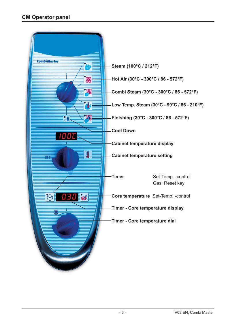
CM Operator panel
Steam (100°C / 212°F)
Hot Air (30°C - 300°C / 86 - 572°F)
Combi Steam (30°C - 300°C / 86 - 572°F)
Low Temp. Steam (30°C - 99°C / 86 - 210°F)
Finishing (30°C - 300°C / 86 - 572°F)
Cool Down
Cabinet temperature display
Cabinet temperature setting
Timer Set-Temp. -control Gas: Reset key
Core temperature Set-Temp. -control Timer - Core temperature display
Timer - Core temperature dial

V03 EN, Combi Master - 4 -
Below are listed the additional functions for the user / operator.
1. Function Cool Down: 1. Cool Down can only be started with interior cabinet door closed. If the door is
open then the word “door” is flashing on the timer/core temperature display. Door must be closed.
2. If Cool down was activated with door closed then “door” appears constantly on the
timer/core temperature display
3. Opening the door does speed up the cool down function. After opening the door “COOL” appears on the timer/core temperature display
4. On the cabinet temperature display the actual cabinet temperature flashes.
5. The maximum on time of cool down is 5 minutes. When the 5 minutes have elapsed, the cool down function stops automatically.
Safety instructions Use cool down only when air baffle plate is positioned correctly. When
opening the cabinet door during cool down, hot air and steam will escape from interior cabinet.
Only trained/authorized personal should use the cool down function..
2. Selection of cleaning program
1) Cool down cabinet below 60°C / 140°F
2) Spray inside cabinet with Rational cleaner
3) Close cabinet door
4) Select „Cool Down
5) Press core temperature key for 10 sec.
6) „CLEn“ will show in cabinet temperature display
7) Press timer key 1x; Cleaning program starts automatically (open cabinet door and rinse interior cabinet after 40 min.) Close door again. Since Software version C1-06-05 a 10 min step hot air will follow to dry the interior cabinet.
8) After end of program, leave cabinet door open over night.
Also refer to sticker „Cleaning“ on the unit
Additional functions
T 60°C (140°F)1.
3.
7. 8.T
10 sec4. T
5.
1X
6.
40 min
10.
9.
10 min
- --
Reinigung - Cleaning - Nettoyage - Limpieza - Pulitura - Reiniging - Limpeza - Tvätt
Puhdistus - Rengjøring - Rengøring - cisteni - cistenie - ciscenje - Tisztitas - Zyszczeni
2.
10.00.381

- 5 - V03 EN, Combi Master
3. Selection of emptying steam generator
This should be done after each installation to verify free drain connection and prior to disconnection the unit for storage.
1) Open cabinet door
2) Select „Cool Down“
3) Press core temperature key for 10 sec.
4) „CLEn“ will be shown in cabinet temperature display
5) Select „SC“ with temperature dial
6) Close water tap
7) Press timer key 1x and remain on „Cool Down“ position for about 45 sec.
4. Selection of descaling program
1) Open cabinet door
2) Select „Cool Down“
3) Press core temperature key for 10 sec.
4) „CLEn“ will be shown in cabinet temperature display
5) Select „CALC“ with temperature dial
6) Press timer key 1x and follow procedure of the decalcification instruction. (See user manual CM).
5. Changing temperature display from °C to °F
1) Select any mode
2) Press timer and core temperature key simultaneously for 10 sec. until Display changes from °C to °F or vice versa
3) Release both keys
Additional functions

V03 EN, Combi Master - 6 -
Function scheme CM electric
B1 Thermocouple cabinetB2 Thermocouple quenching / Steam controlB3 Thermocouple core temperatureB5 Thermocouple steam generator (preheating, 180°C (356°F) max) F3 Safety temperature limiter steam generator 160°C / 320°FF4 Safety temperature limiter cabinet 360°C / 680°F Y1 Solenoid valve fillingY2 Solenoid valve quenching M1 Fan motor (without jumper)M4 Pump SC-Automatic S2 Level electrodeS3 Door contact switch
CM 201/202 only:M2 Fan motor top (with jumper)
B1B3
F4
M4
Y1 Y2
B2
M1
S2
B5
F3
S3

- 7 - V03 EN, Combi Master
Y1 Y2
B2
B1
Intelligent steam control via quenching sensor
Temp.
t (s)
B1 - 100°C(212°F)
70°C (158°F)
1. Filling of interior cabinet based on time and temperature control of B2 quenching sensor; (cabinet if fully filled with steam and all sur-faces have reached steam temperature).
2. After steam saturation inside cabinet steam will also fill quenching chamber
3. After reaching quenching temperature (B2) quenching solenoid Y2 will be activated. Depending on the frequency of temperature raise of the quenching sensor B2 the duration of the next steam supply is calculated.
B2 temperature with partial load B2 temperature with full load
4. The amount of steam inside the cabinet is directly depending on the temperature varia-tion of quenching sensor B2.
Y1 Y2
B2
B1
Y1 Y2
B2
B1
Steam control CM

V03 EN, Combi Master - 8 -
X7
X19
X20
F1 F2
Transformer
0,1 AT 2 AT
1
1
X7
X19
X20
X18
X23
X31
RS 485
X8
X12
X26
X27
X32X24
X30RS 232
X63
X3X4X6X2
X50
2 AT
12
34
onoff
1 1
1
1
1
1
1
F6.12 AT
X16 F6
42.00.004
Index “E” ab 04-2004
42.00.047
Index “F/G” ab 02-2006
* Since February 2006 PCB 42.00.004 is replaced by 42.00.047. The transformer on the new PCB 42.00.047 is no more existing and replaced by external transformer 40.00.227 (conversion kit: 87.00.139, pls. see Technical info 04-2006)
** As of 12/2006 option Sicotronic is not installed in CM units as a standard. For retro fitting see TI 12/2006 and MI 05/2009.
PCB
1
TemperaturPoti
Counting sequence
X2 B3 Core temperature
X3 B1 Interior cabinet
X4 B2 Quenching / Steam control
X6 B5 Steam generator
X7 ON - OFF switch X8 Buzzer
X12 Level electrode
X 16 power supply from transformer T1* 42.00.047 as of 02-2006
X18 SC - pump
X19 Solenoid valves
X20 Energy management system / Sicotronic**
X23 Vent hood (signal door open / closed)
X24 SSR
X26 SSR pulsing (USA version only)
X27 Door contact switch
X30 Serial interface (RS232)
X31 Bus interface
X32 Timer / Core Temp. Poti.
X50 external EEPROM
X63 Not used

- 9 - V03 EN, Combi Master
V03 EN, Combi Master - 10 -Combi Master - 10 - - 10 -
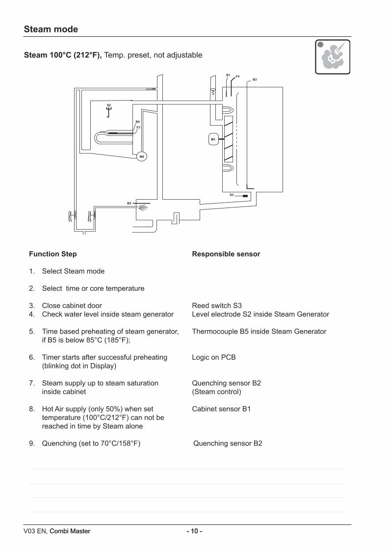
Steam 100°C (212°F), Temp. preset, not adjustable
B1B3
F4
M4
Y1 Y2
B2
M1
S2
B5
F3
S3
Steam mode
Function Step Responsible sensor
1. Select Steam mode
2. Select time or core temperature
3. Close cabinet door Reed switch S34. Check water level inside steam generator Level electrode S2 inside Steam Generator
5. Time based preheating of steam generator, Thermocouple B5 inside Steam Generator if B5 is below 85°C (185°F);
6. Timer starts after successful preheating Logic on PCB (blinking dot in Display)
7. Steam supply up to steam saturation Quenching sensor B2 inside cabinet (Steam control) 8. Hot Air supply (only 50%) when set Cabinet sensor B1 temperature (100°C/212°F) can not be reached in time by Steam alone
9. Quenching (set to 70°C/158°F) Quenching sensor B2
- 11 - V03 EN, Combi Master
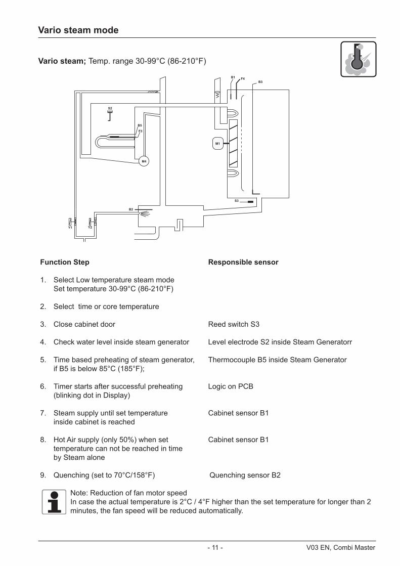
Vario steam; Temp. range 30-99°C (86-210°F)
B1B3
F4
M4
Y1 Y2
B2
M1
S2
B5
F3
S3
Vario steam mode
Function Step Responsible sensor
1. Select Low temperature steam mode Set temperature 30-99°C (86-210°F)
2. Select time or core temperature
3. Close cabinet door Reed switch S3
4. Check water level inside steam generator Level electrode S2 inside Steam Generatorr
5. Time based preheating of steam generator, Thermocouple B5 inside Steam Generator if B5 is below 85°C (185°F);
6. Timer starts after successful preheating Logic on PCB (blinking dot in Display)
7. Steam supply until set temperature Cabinet sensor B1 inside cabinet is reached 8. Hot Air supply (only 50%) when set Cabinet sensor B1 temperature can not be reached in time by Steam alone
9. Quenching (set to 70°C/158°F) Quenching sensor B2
Note: Reduction of fan motor speedIn case the actual temperature is 2°C / 4°F higher than the set temperature for longer than 2 minutes, the fan speed will be reduced automatically.

V03 EN, Combi Master - 12 -Combi Master - 12 - - 12 -
Combi steam; Temp. range 30-300°C (86-572°F)
B1B3
F4
M4
Y1 Y2
B2
M1
S2
B5
F3
S3
Combi steam mode
Function Step Responsible sensor
1. Select Combi mode Set temperature 30-300°C (86-572°F)
2. Select time or core temperature
3. Close cabinet door Reed switch S3
4. Check water level inside steam generator Level electrode S2 inside Steam Generatorr
5. Time based preheating of steam generator, Thermocouple B5 inside Steam Generator if B5 is below 85°C (185°F);
6. Timer starts after successful preheating Logic on PCB (blinking dot in Display)
7. Hot Air supply until set temperature Cabinet sensor B1 inside cabinet. Hot air has priority 8. Steam supply up to steam saturation Quenching sensor B2 inside cabinet (Steam Control)
9. Quenching (set to 70°C/158°F) Quenching sensor B2
Note: Reduction of fan motor speedIn case the actual temperature in the range of 30-99°C (86 - 210°F) is 2°C / 4°F higher than the set temperature for longer than 2 minutes, the fan speed will be reduced automatically.

- 13 - V03 EN, Combi Master
F
Finishing: Temp. range 30-300°C (86-572°F)B1
B3F4
M4
Y1 Y2
B2
M1
S2
B5
F3
S3
Finishing mode
Function Step Responsible sensor
1. Select Finishing mode Recommended temperature 30-300°C (86-572°F)
2. Select time or core temperature
3. Close cabinet door Reed switch S3
4. Check water level inside steam generator Level electrode S2 inside Steam Generator
5. Time based preheating of steam generator, Thermocouple B5 inside Steam Generator if B5 is below 85°C (185°F);
6. Timer starts after successful preheating Logic on PCB (blinking dot in Display)
7a. Electric units: alternating 12 sec. Hot Air Cabinet sensor B1 6 sec. Steam Quenching sensor B2 7b Gas units: alternating 30 sec. Hot Air Cabinet sensor B1 15 sec. Steam Quenching sensor B2
8. Quenching (set to 70°C/158°F) Quenching sensor B2
Note: Reduction of fan motor speedIn case the actual temperature in the range of 30-99°C (86 - 210°F) is 2°C / 4°F higher than the set temperature for longer than 2 minutes, the fan speed will be reduced automati-cally.

V03 EN, Combi Master - 14 -Combi Master - 14 - - 14 -
Hot Air: Temp. range 30-300°C (86-572°F)B1
B3F4
M4
Y1 Y2
B2
M1
S2
B5
F3
S3
Hot air mode
Function Step Responsible sensor
1. Select Hot Air mode Set temperature 30-300°C (86-572°F)
2. Select time or core temperature
3. Close cabinet door Reed switch S3
4. Timer starts immediately Logic on PCB
5. Hot Air supply until set temperature Cabinet sensor B1 is reached
6. Quenching (set to 90°C/194°F) Quenching sensor B2
Note: Reduction of fan motor speedIn case the actual temperature in the range of 30-99°C (86-210°F) is 2°C / 4°F higher than the set temperature for longer than 2 minutes, the fan speed will be reduced automatically.
- 15 - V03 EN, Combi Master
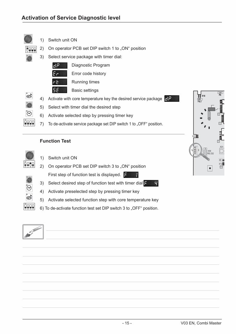
1) Switch unit ON
2) On operator PCB set DIP switch 1 to „ON“ position
3) Select service package with timer dial:
Diagnostic Program
Error code history
Running times
Basic settings
4) Activate with core temperature key the desired service package
5) Select with timer dial the desired step
6) Activate selected step by pressing timer key
7) To de-activate service package set DIP switch 1 to „OFF“ position.
Function Test
1) Switch unit ON
2) On operator PCB set DIP switch 3 to „ON“ position
First step of function test is displayed.
3) Select desired step of function test with timer dial
4) Activate preselected step by pressing timer key
5) Activate selected function step with core temperature key
6) To de-activate function test set DIP switch 3 to „OFF“ position.
X
X
X
X
X31
X8
X12
X30RS 232
X63
2 AT
12
34
on
off
1
1
1
1
F6.12 AT
X16 F6
1 2 3 4
on
1 2 3 4
on
Activation of Service Diagnostic level
1 2 3 4
on
1 2 3 4
on

V03 EN, Combi Master - 16 -Combi Master - 16 - - 16 -
*With SW Version C1-06-05 the flame current will show as 20-24μA (This value must be divided by 4 to get the correct flame current e. g. 22:4 = 5,5μA.) Starting with SW version C1-07-01 the actual flame current is shown .
dP - Diagnostic Program
Description Connection CabinetDisplay
Time dis-play
Software Version SoftwareVersion: C - 1
Software 07.01
B1 Cabinet sensor X 3 actual value max value Reset by pressing for 5 sec.
B2 Quenching sensor X 4 actual value max value Reset by pressing for 5 sec.
B3 Core sensor X 2 actual value max value Reset by pressing for 5 sec.
B5 Steam generator sen-sor X 6 actual value max value Reset by pressing
for 5 sec.
PCB temperature actual value max value Reset by pressing for 5 sec.
S3 Door contact X27:(1-2) 1 - 0 0 = door open1 = door closed
S2 Water level steam generator
X12:(1-4) S2 X19:(1-3) Y1 S2: 0 - 1 Y1: 1 - 0
Steam elements 0 - off; 1 - 50%; 2 - 100%Gas: 0 - off; 1-100%
actual Temp. B5 0 - 50 - 100
Hot Air elements 0 - off; 1 - 50%; 2 - 100%Gas: 0 - off; 1-100%
actual Temp. B1 0 - 50 - 100
Speed fan motor bottomTable unit/floor unit bottom BUS Set rpm actual rpm
Speed fan motor topfloor unit top BUS Set rpm actual rpm only floor model 201/202
Sicotronic X 20 1 - 0
SSR control X24 1 - 0 0 = US version only
Unit size and type 61 - 202 ELE - GAS
Flame current Steam x.x μA* since SW Version: C1-06-05 (flame current)
Flame current Hot airTable unit/floor unit top
Hot air top x.x μA*
since SW Version: C1-06-05 (flame current)
Flame current Hot airfloor unit bottom
Hot air bot-tom x.x μA*
since SW Version: C1-06-05 (flame current)
+
+
+
+
+

- 17 - V03 EN, Combi Master
Er - Error Codes / Error messagesFailure code: ErAs of software version C1-07-01 the last 10 stored failures are shown
Er When timer key is pressed the error code will be displayed. e. g.Er# Code see failure chartEr1 3 B1 cabinet sensor defectiveEr2---Er10
Gas failure GE: only gas units, failure description see training module „Gas“ Since software version C1-07-01 the last 16 gas error messages (GE11 - GE26) are shown in addition to the general error messages. These error codes are generated by the ignition boxGE# Code see failure chart training module „Gas“GE11 20 No rpm signalGE13 --- GE 26
The following error codes are shown to the operator:*For showing information of the cabinet display press core temperature key
Time display
Cabinet display Failure explanation Description / remedy
H2O open Lack of water / open water tap
Change Polarity Phase / Neutral (only gas units)
Reset Gas Flame detection after ignition faulty
external EEPROM Not initialised
Time out of external power optimising system
Heating blocked by the extern. energyopti-mising system for longer 2 min.
B1 Interior cabinet sensor Sensor broken
B2 Quenching sensor Sensor broken
B3 Core sensor Sensor broken
B5 Sensor steam generator Sensor broken
Thermocouple on PCB Sensor broken
Poti interior cabinet Defective
Poti timer/core temperature Defective
external EEPROM Defective
Mode switch After 5 sec switching on the unit, a cooking mode couldn‘t be identified
* Fan motor 1 (table/floor units bottom)Fan motor 1 (table/floor units bottom)Fan motor 2 (floor units top)Fan motor 2 (floor units top)
St = Status (probably Motor defect)Co = Communication, (Bus failure)

V03 EN, Combi Master - 18 -Combi Master - 18 - - 18 -
*For showing information of the cabinet display press core temperature key
Error codes
Time display
Cabinet display Failure explanation Description / remedy
M4 SC-pump Mal function
Solenoid valve filling Y1(failure can only occur during the descaling program)
Mal function
PCB temperature above 85°C (185°F)
Steam generator Temperature B5 above 180°C (356°F)
Steam generator Temperature B5 below -5°C (23°F)
Interior cabinet temp. Temperature B1 above 340°C (644°F)
Free
*Ignition box 1 (table/floor units top)Ignition box 2 (floor units bottom) Ignition box does not reply, Bus failure
* Ignition box 1 Steam (table/floor units top)Ignition box 1 Hot air (table/floor units top)Ignition box 2 Hot air (floor units bottom)
Ignition box defective (change box)
* Ignition box 1 Steam (table/floor units top)Ignition box 1 Hot air (table/floor units top)Ignition box 2 Hot air (floor units bottom)
Testing of ignition and monitoringnecessary
Free
EEPROM Actual data structure of the EEPROM does not match with the software; flash pcb first

- 19 - V03 EN, Combi Master
+
+
+
+
+
+
1 433
Service Level: rt -- Running TimeDescription *Timer display
Temp. displayComment
Total S3 door openings number Reset by pressing for 5 sec.
Total time Y1 valve filling min Reset by pressing for 5 sec.
Total time Y2 valve quenching min Reset by pressing for 5 sec.
Total time M4 SC-pump min Reset by pressing for 5 sec.
Total time steam heating time hrs Reset by pressing for 5 sec.
Total time hot air heating time hrs Reset by pressing for 5 sec.
Total time steam mode hrs Can not be reset
Total time hot air mode hrs Can not be reset
Total time combination mode hrs Can not be reset
Total time vario steam mode hrs Can not be reset
Total time finishing mode hrs Can not be reset
Total time cool down hrs Can not be reset
Total running time unit hrs Can not be reset
* On the timer display values up to 999 are shown. In case of values above 999 on the temperature display the corresponding thousand numbers are shown., e. g. 1433: Temp. display timer display
rt - Running Times

V03 EN, Combi Master - 20 -Combi Master - 20 - - 20 -
Switch unit OFF and ON again after any changes made!
Select desired step with timer dial (fan motor and heating elements are automatically OFF)
Activate selected step with timer key
Steam heating time since last SC-Automatic
Press time and core key simultaneously for 5 seconds to set steam heating time (SE2) to preset steam heating time plus 1 minute (default 45+1min) => test function for SC-Automatic
Preset Steam heating time until SC-Automatic (default 60min)
Press time key and adjust preset steam heating time from 20 - 120 minutes with timer dial
Flushing time SC-Automatic (default 45 seconds)
Press time key and adjust flushing time of SC-Automatik from 30 - 90 seconds with timer dial
Operation SC pump (oFF - continuous or on - pulsing)
Press time key and select „on“ or „oFF“ with timer dial
Show mode (on - oFF) SHO
Press time key and select „on“ or „oFF“ with timer dial
Setting new gas type (G20, G25, G30, G31, 13A)
Press time key, keep it pressed and select new gas type with timer dial Confirm new gas type by pressing core temperature key once. Corresponding gas blower speed is automatically adjusted NOTE: After changing gas type a waste gas analysis must be carried out in the function test.
Presetting of CO2 screw in mm on gas valve after gas type modification / changing gas valve
Press time key, keep it pressed and select with timer dial “ST“ for steam, “HA1“ for hot air top or “HA2“ for hot air bottom (only 201/202) with timer dial; Average length in mm of CO2 screw on gas valve is shown on timer display
+
SE - Basic Settings
- 21 - V03 EN, Combi Master
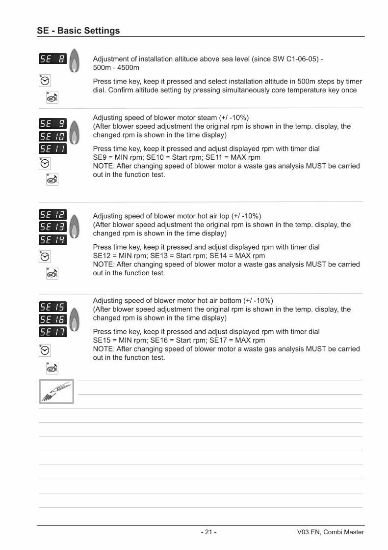
Adjustment of installation altitude above sea level (since SW C1-06-05) - 500m - 4500m
Press time key, keep it pressed and select installation altitude in 500m steps by timer dial. Confirm altitude setting by pressing simultaneously core temperature key once
Adjusting speed of blower motor steam (+/ -10%) (After blower speed adjustment the original rpm is shown in the temp. display, the changed rpm is shown in the time display)
Press time key, keep it pressed and adjust displayed rpm with timer dial SE9 = MIN rpm; SE10 = Start rpm; SE11 = MAX rpm NOTE: After changing speed of blower motor a waste gas analysis MUST be carried out in the function test.
Adjusting speed of blower motor hot air top (+/ -10%) (After blower speed adjustment the original rpm is shown in the temp. display, the changed rpm is shown in the time display)
Press time key, keep it pressed and adjust displayed rpm with timer dial SE12 = MIN rpm; SE13 = Start rpm; SE14 = MAX rpm NOTE: After changing speed of blower motor a waste gas analysis MUST be carried out in the function test.
Adjusting speed of blower motor hot air bottom (+/ -10%) (After blower speed adjustment the original rpm is shown in the temp. display, the changed rpm is shown in the time display)
Press time key, keep it pressed and adjust displayed rpm with timer dial SE15 = MIN rpm; SE16 = Start rpm; SE17 = MAX rpm NOTE: After changing speed of blower motor a waste gas analysis MUST be carried out in the function test.
SE - Basic Settings

V03 EN, Combi Master - 22 -Combi Master - 22 - - 22 -
F - Function test
NOTE: In Function test components are NOT protected against overload!
Function Connection PCB
Cabinet display
Time display
Comment
Steam 50%, Electric unit X24:(1-2) actual temp.B5
steam generator 1 / 0 Gas: no function
Steam 100%Electric unit X24:(1-2)+(5-6) actual temp.B5
steam generator 1 / 0 Gas: no function
Hot air 50%Electric unit X24:(7-8) actual temp.B1
cabinet 1 / 0 Gas: no function
Hot air 100% Electric unit X24:(7-8)+(3-4) actual temp.B1
cabinet 1 / 0 Gas: no function
Steam Gas unit BUS actual temp.B5 B5 steam generator 1 / 0 Electric:
no function
Hot air top Gas unittable / floor top BUS actual temp.B1
cabinet 1 / 0 Electric: no function
Hot air bottom Gas floor unit bottom BUS actual temp.B1
cabinet 1 / 0 Electric: no function
Bottom Motor MAX table / floor bottom BUS Set rpm Act. rpm
Bottom Motor MIN table / floor bottom BUS Set rpm Act. rpm
Top Motor MAX floor units top BUS Set rpm Act. rpm
Function Test
1) Switch unit ON
2) On operator PCB set DIP switch 3 to „ON“ position
First step of function test is displayed.
3) Select desired step of function test with timer dial
4) Activate preselected step by pressing timer key
5) Activate selected function step with core temperature key
6) To de-activate function test set DIP switch 3 to „OFF“ position.
1 2 3 4
on
1 2 3 4
on
- 23 - V03 EN, Combi Master
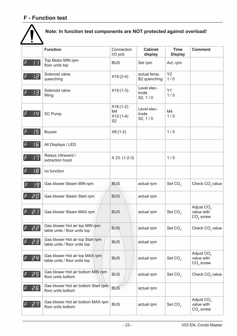
F - Function test
Note: In function test components are NOT protected against overload!
Function Connection I/O pcb
Cabinet display
Time Display
Comment
Top Motor MIN rpmfloor units top BUS Set rpm Act. rpm
Solenoid valvequenching X19:(2-4) actual temp.
B2 quenchingY2 1 / 0
Solenoid valvefilling
X19:(1-3) Level elec-trode S2, 1 / 0
Y1 1 / 0
SC Pump
X18:(1-2) M4 X12:(1-4) S2
Level elec-trode S2, 1 / 0
M4 1 / 0
Buzzer X8:(1-2) 1 / 0
All Displays / LED
Relays Ultravent / extraction hood X 23: (1-2-3) 1 / 0
no function
Gas blower Steam MIN rpm BUS actual rpm Set CO2 Check CO2 value
Gas blower Steam Start rpm BUS actual rpm
Gas blower Steam MAX rpm BUS actual rpm Set CO2
Adjust CO2 value with CO2 screw
Gas blower Hot air top MIN rpmtable units / floor units top BUS actual rpm Set CO2 Check CO2 value
Gas blower Hot air top Start rpmtable units / floor units top BUS actual rpm
Gas blower Hot air top MAX rpmtable units / floor units top BUS actual rpm Set CO2
Adjust CO2 value with CO2 screw
Gas blower Hot air bottom MIN rpmfloor units bottom BUS actual rpm Set CO2 Check CO2 value
Gas blower Hot air bottom Start rpmfloor units bottom BUS actual rpm
Gas blower Hot air bottom MAX rpmfloor units bottom BUS actual rpm Set CO2
Adjust CO2 value with CO2 screw
V03 EN, Combi Master - 24 -Combi Master - 24 - - 24 -
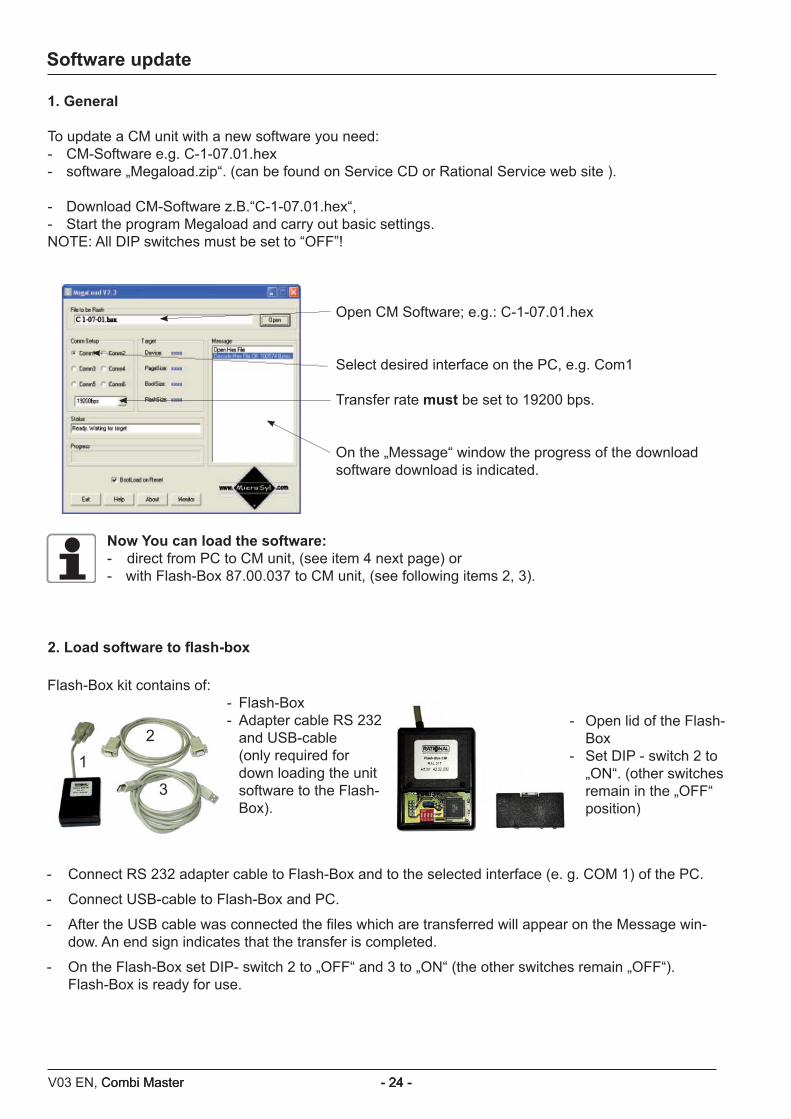
1. General
To update a CM unit with a new software you need: - CM-Software e.g. C-1-07.01.hex- software „Megaload.zip“. (can be found on Service CD or Rational Service web site ).
- Download CM-Software z.B.“C-1-07.01.hex“,- Start the program Megaload and carry out basic settings.NOTE: All DIP switches must be set to “OFF”!
Open CM Software; e.g.: C-1-07.01.hex
Select desired interface on the PC, e.g. Com1 Transfer rate must be set to 19200 bps.
On the „Message“ window the progress of the download software download is indicated.
Now You can load the software:- direct from PC to CM unit, (see item 4 next page) or - with Flash-Box 87.00.037 to CM unit, (see following items 2, 3).
Flash-Box kit contains of:- Flash-Box- Adapter cable RS 232
and USB-cable (only required for
down loading the unit software to the Flash-Box).
- Open lid of the Flash-Box
- Set DIP - switch 2 to „ON“. (other switches remain in the „OFF“ position)
- Connect RS 232 adapter cable to Flash-Box and to the selected interface (e. g. COM 1) of the PC.
- Connect USB-cable to Flash-Box and PC.
- After the USB cable was connected the files which are transferred will appear on the Message win-dow. An end sign indicates that the transfer is completed.
- On the Flash-Box set DIP- switch 2 to „OFF“ and 3 to „ON“ (the other switches remain „OFF“). Flash-Box is ready for use.
2. Load software to flash-box
Software update
12
3
- 25 - V03 EN, Combi Master
12
34
on
X7
X19
X20
X18
X23
X31
RS 485
X8
X12
X16
X17
X26
X27
X32X24
X63
F6.1
F6
X3X4X6X2
X50
on
off
0,1 AT
2 AT
X7
X19
X20
F1 F20,1 AT 2 AT
Transformer X16
42.00.004 42.00.047
X30RS 232
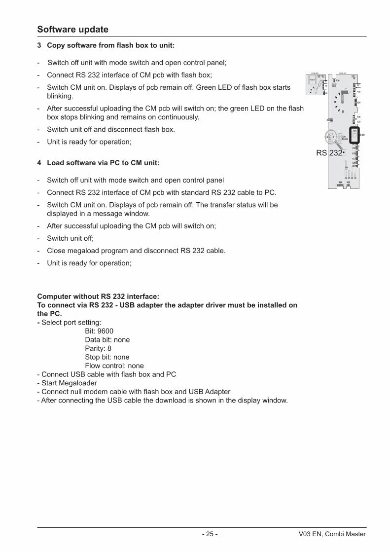
3 Copy software from flash box to unit:
- Switch off unit with mode switch and open control panel;
- Connect RS 232 interface of CM pcb with flash box;
- Switch CM unit on. Displays of pcb remain off. Green LED of flash box starts blinking.
- After successful uploading the CM pcb will switch on; the green LED on the flash box stops blinking and remains on continuously.
- Switch unit off and disconnect flash box.
- Unit is ready for operation;
4 Load software via PC to CM unit:
- Switch off unit with mode switch and open control panel
- Connect RS 232 interface of CM pcb with standard RS 232 cable to PC.
- Switch CM unit on. Displays of pcb remain off. The transfer status will be displayed in a message window.
- After successful uploading the CM pcb will switch on;
- Switch unit off;
- Close megaload program and disconnect RS 232 cable.
- Unit is ready for operation;
Computer without RS 232 interface: To connect via RS 232 - USB adapter the adapter driver must be installed on the PC. - Select port setting: Bit: 9600 Data bit: none Parity: 8 Stop bit: none Flow control: none - Connect USB cable with flash box and PC - Start Megaloader - Connect null modem cable with flash box and USB Adapter - After connecting the USB cable the download is shown in the display window.
RS 232
Software update
V03 EN, Combi Master - 26 -Combi Master - 26 - - 26 -
Changing pcb / changing EEPROM / Error „E1 / E10“
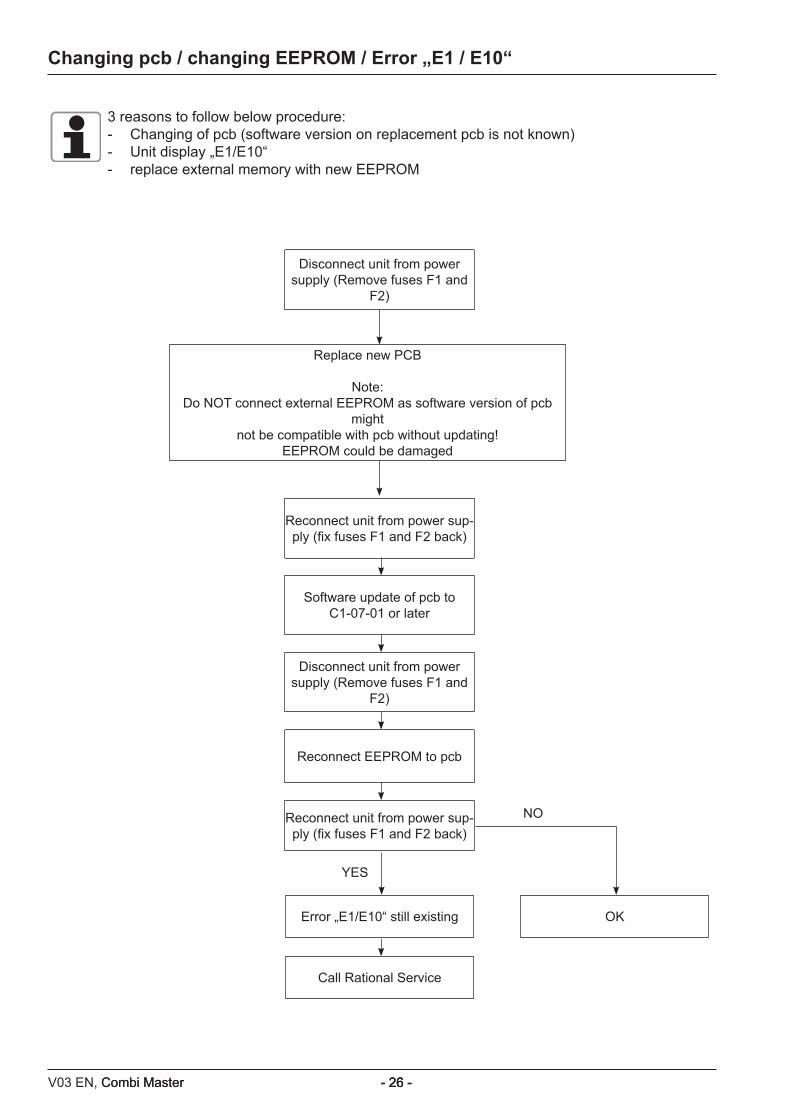
Disconnect unit from power supply (Remove fuses F1 and
F2)
Reconnect unit from power sup-ply (fix fuses F1 and F2 back)
Software update of pcb to C1-07-01 or later
Disconnect unit from power supply (Remove fuses F1 and
F2)
Reconnect EEPROM to pcb
Reconnect unit from power sup-ply (fix fuses F1 and F2 back)
Error „E1/E10“ still existing
Call Rational Service
OK
Replace new PCB
Note:Do NOT connect external EEPROM as software version of pcb
might not be compatible with pcb without updating!
EEPROM could be damaged
3 reasons to follow below procedure:- Changing of pcb (software version on replacement pcb is not known)- Unit display „E1/E10“ - replace external memory with new EEPROM
YES
NO

- 27 - V03 EN, Combi Master
HACCP Protocol
In order to download the HACCP data via Hyper terminal at a CM unit the DIP switch “2” must be set to “ON” position. This changes the tranfer rate from 19200 to 9600 baud. Note: During the period of a software update of a CM unit all DIP switches must be set to “OFF”.
HACCP protocol

V03 EN, Combi Master - 28 -Combi Master - 28 - - 28 -
Rat
ion
al S
CC
-Lin
ie:
Leis
tun
gst
eil
Rat
ion
al S
CC
-Lin
e:
Pow
er c
ircu
itR
atio
nal
Lin
ea S
CC
: C
ircu
ito
di a
limen
tazi
on
eR
atio
nal
SC
C-L
ine:
C
ircu
it d
e p
uis
san
ceR
atio
nal
Lin
ea S
CC
: C
ircu
ito
de
la e
ner
gía
K1
BN BU
M5
M 1 ~A2
A1
N/O
1 2
BK
3 4
OG
5 6
VT
GY BN BU
W0
BK
BN
BK
BU
PE
YE/GN YE/GN
BKF1 6,
3A F2 6,3A
Z1
L1 L2 L3 N PEVT
R1
3x3k
W9k
W D
1/D
2
1 2
V1
Leis
tung
shal
blei
ter
solid
stat
e re
lay
A+
A-
B+B-
A1/
B1
A2
B2
3 4
5 6
X33
2211
R2
3x3k
W9k
W D
1/D
2
1 23
D1
H
L2
4
3 4
5 6
V2
Leis
tung
shal
blei
ter
solid
stat
e re
lay
A+
A-
B+B-
A1/
B1
A2
B2
R4
6x3k
W18
kW H
L1/H
L2
1 2
X34
2211
3 4
3
D2
H
L1
5 64
7 8
9 10
11 12
BK OG VT BU
YE/G
N
3NA
C 4
00 -
415V
M1
M ~F2
0
6,3A .
F21
6,3A .
33 22
X2211
BN
77 66 55 44 33 22BU
T4
~-
12V
0V
0V200V
208V
220V
230V
240V
250V
X5911
22
X6711
M5
M20
1-20
2
W17
A4
PCB K1 N
/O
14 13
X7
11
GY BNRD
F31 2
F41 2
33
Ein/
Aus
Sch
alte
r
S1
K1A
1
A222
RDX4
611
T1St
euer
traf
oC
ontr
oltr
ansf
orm
er2,5V
0V
2,5V
11,5V
11,5V
12V
12V
250V
240V
230V
220V
208V
200V
0V
2233
H1
Gar
raum
bele
ucht
ung
Inte
rior c
abin
et li
ght W
11
F5 1,6A
.1122
W25
X16 11 33
22
X56
44 11
F6.1
1AT
F6 2AT .
X57
7766
5544
3322
Wiring diagram Power circuit 3NAC 400-415V

- 29 - V03 EN, Combi Master
Rat
ion
al S
CC
-Lin
ie:
Leis
tun
gst
eil
Rat
ion
al S
CC
-Lin
e:
Pow
er c
ircu
itR
atio
nal
Lin
ea S
CC
: C
ircu
ito
di a
limen
tazi
on
eR
atio
nal
SC
C-L
ine:
C
ircu
it d
e p
uis
san
ceR
atio
nal
Lin
ea S
CC
: C
ircu
ito
de
la e
ner
gía
K1
BN BU
M5
M 1 ~A2
A1
N/O
1 2
BK
3 4
OG
5 6
VT
GY BN BU
W0
BK
BN
BK
PE
YE/GN YE/GN
BKF1 6,
3A F2 6,3A
Z1
L1 L2 L3 PEVT
R1
3x3k
W9k
W D
1/D
2
1 2
V1
Leis
tung
shal
blei
ter
solid
stat
e re
lay
A+
A-
B+B-
A1/
B1
A2
B2
3 4
5 6
X33
1122 R2
3x3k
W9k
W D
1/D
2
1 23
D1
H
L2
4
3 4
5 6
V2
Leis
tung
shal
blei
ter
solid
stat
e re
lay
A+
A-
B+B-
A1/
B1
A2
B2
R4
6x3k
W18
kW H
L1/H
L2
1 2
X34
1122
3 4
3
D2
H
L1
5 64
7 8
9 10
11 12
BK OG VT
YE/G
N
3AC
200
- 24
0V
M1
M ~F2
0
6,3A .
F21
6,3A .
33 22
X2211
BN
77 66 55 44 33 22BU
T4
~-
12V
0V
0V200V
208V
220V
230V
240V
250V
X5911
22
X6711
M5
M20
1-20
2
W17
A4
PCB K1 N
/O
14 13
X7
11GY BNRD
F31 2
F41 2
33
Ein/
Aus
Sch
alte
r
S1
K1A
1
A222
RD
X46
11
T1St
euer
traf
oC
ontr
oltr
ansf
orm
er
2,5V
0V
2,5V
11,5V
11,5V
12V
12V
250V
240V
230V
220V
208V
200V
0V
2233
H1
Gar
raum
bele
ucht
ung
Inte
rior c
abin
et li
ght W
11
F5 1,6A
.1122
W25
X16 11 33
22
X56
44 11
F6.1
1AT
F6 2AT .
X57
7766
5544
3322
Wiring diagram Power circuit 3AC 200-240V

V03 EN, Combi Master - 30 -Combi Master - 30 - - 30 -
Rat
ion
al S
CC
-Lin
ie:
Leis
tun
gst
eil
Rat
ion
al S
CC
-Lin
e:
Pow
er c
ircu
itR
atio
nal
Lin
ea S
CC
: C
ircu
ito
di a
limen
tazi
on
eR
atio
nal
SC
C-L
ine:
C
ircu
it d
e p
uis
san
ceR
atio
nal
Lin
ea S
CC
: C
ircu
ito
de
la e
ner
gía
K1
BN BU
M5
M 1 ~A2
A1
N/O
1 2
BK
3 4
OG
5 6
VT
GY BN BU
W0
BK
BN
BK
PE
YE/GN YE/GN
BKF1 6,
3A F2 6,3A
Z1
L1 L2 L3 PEVT
R1
3x3k
W9k
W D
1/D
2
1 2
V1
Leis
tung
shal
blei
ter
solid
stat
e re
lay
A+
A-
B+B-
A1/
B1
A2
B2
3 4
5 6
X33
1122 R2
3x3k
W9k
W D
1/D
2
1 23
D1
H
L2
4
3 4
5 6
V2
Leis
tung
shal
blei
ter
solid
stat
e re
lay
A+
A-
B+B-
A1/
B1
A2
B2
R4
6x3k
W18
kW H
L1/H
L2
1 2
X34
1122
3 4
3
D2
H
L1
5 64
7 8
9 10
11 12
BK OG VT
YE/G
N
3AC
400
- 48
0V
BN
77 66 55 44 33 22BU
T4
~-
12V
0V
0V200V
208V
220V
230V
240V
250V
X5911
22
X6711
M5
M20
1-20
2
W17
A4
PCB K1 N
/O
14 13
X7
11
GY BNRD
F31 2
F41 2
33
Ein/
Aus
Sch
alte
r
S1
K1A
1
A222
RDX4
611
T1St
euer
traf
oC
ontr
oltr
ansf
orm
er
2,5V
0V
2,5V
11,5V
11,5V
12V
12V
250V
240V
230V
220V
208V
200V
0V
2233
H1
Gar
raum
bele
ucht
ung
Inte
rior c
abin
et li
ght W
11
F5 1,6A
.1122
W25
X16 11 33
22
X56
44 11
F6.1
1AT
F6 2AT .
X57
7766
5544
3322
55 44 33 22
T3
Sond
ertr
afo
Spec
ial t
rans
form
er
0V400V
415V
440V
480V
0V230V
X7211
F7 0,8A
22
X71
11
F86,
3A
F96,
3A
F10
6,3A
M1
M ~44 33 22
X22
11
Wiring diagram Power circuit 3AC 400-480V

- 31 - V03 EN, Combi Master
0Ve
rsio
n
MO
DU
L 2
Hei
ßluf
thei
zung
/Dam
pfhe
izun
gH
ot a
ir he
atin
g/St
eam
hea
ting
Erst
ellt
von
Crea
ted
by
Dat
umD
ate
Blat
tPa
ge
PA
2
30.0
4.20
04
K1:5 / 1.08
W16
AW
G 8
(4x)
VT R1
6x3k
W18
kW D
1
1 2 ThermoelementDampfgenerator
Thermocouplesteam generator
K1:1 / 5.00
BK
K1:3 / 1.08 V3
Leis
tung
shal
blei
ter
solid
stat
e re
lay
A+
A-
B+B-
A1/
B1
A2
B2
3 4
OG
5 6
X35
12
7 83
D1
H
L2
4
9 10
11 12
R2
6x3k
W18
kW D
2
1 2
3 4
5 6
7 8
9 10
11 12
V1
Leis
tung
shal
blei
ter
solid
stat
e re
lay
A+
A-
B+B-
A1/
B1
A2
B2
R3
6x3k
W18
kW D
2
1 2
WH
WH
WH
WH
GY
GY
GY
GY
X24
1
X33
1+D1
-D1
+HL2
-HL23 42 2
3 3
5 6
D1
H
L2
4 4
7 8V2
Leis
tung
shal
blei
ter
solid
stat
e re
lay
A+
A-
B+B-
A1/
B1
A2
B2
9 10
5
X34
1
11 12+D2
-D2
+HL1
-HL1
6 2
7 3
R4
6x5k
W30
kW H
L1/H
L2
1 2
D2
H
L1
8 4
3 4
5 6
7 8
9 10
11 12
R5
6x5k
W30
kW H
L1/H
L2
1 2
3 4
5 6V4
Leis
tung
shal
blei
ter
solid
stat
e re
lay
A+
A-
B+B-
A1/
B1
A2
B2
7 8
X36
1
9 1023
11 12
D2
H
L1
4
A1
I/O
-PCB
0
98
76
54
32
10
Wiring diagram Steam / Hot air heating 3NAC 400V
V03 EN, Combi Master - 32 -Combi Master - 32 - - 32 -
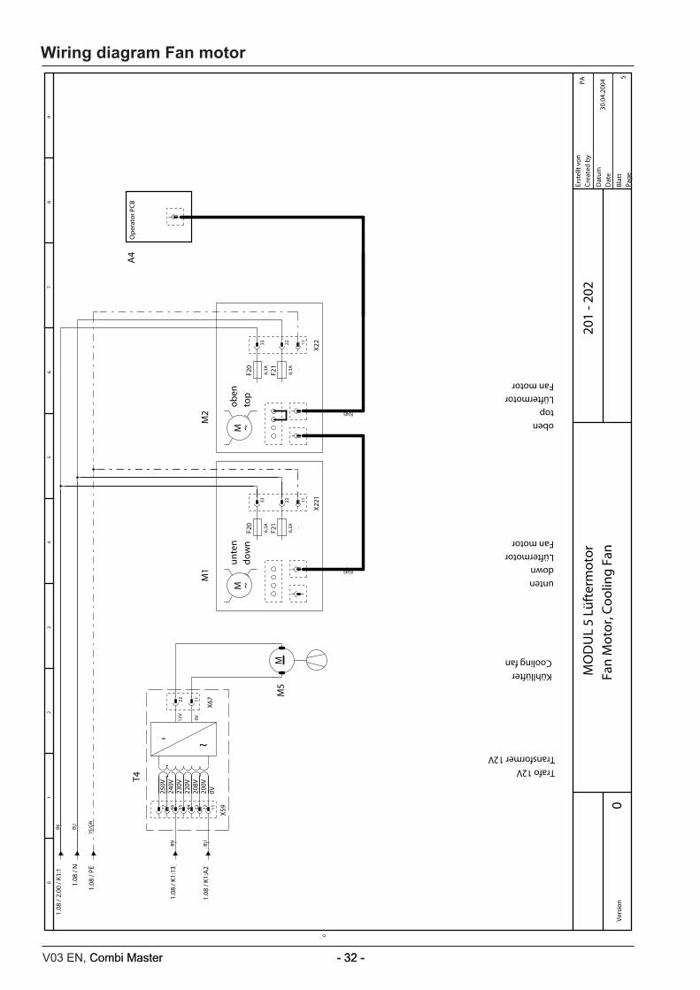
0Ve
rsio
n
MO
DU
L 5
Lüft
erm
otor
Fan
Mot
or, C
oolin
g Fa
n20
1 - 2
02Er
stel
lt vo
nCr
eate
d by
Dat
umD
ate
Blat
tPa
ge
PA
5
30.0
4.20
04
1.08
/ K1
:13
BN
77 66 55 44 33 22
1.08
/ 2.
00 /
K1:1
1.08
/ N
1.08
/ PE
1.08
/ K1
:A2
BU
T4
Trafo 12VTransformer 12V
~-
12V
0V
0V200V
208V
220V
230V
240V
250V
BK BU
YE/G
N
X5911
22
X6711
M5
KühllüfterCooling fanM
untendownLüftermotorFan motor
unte
ndo
wn
M1
M ~
RJ45
F20
6,3A .
F21
6,3A .
33 22
X22111
obentopLüftermotorFan motor
oben
top
M2
M ~
RJ45
F20
6,3A .
F21
6,3A .
33 22
X2211
A4
Ope
rato
r PCB
0
98
76
54
32
10
Wiring diagram Fan motor
- 33 - V03 EN, Combi Master
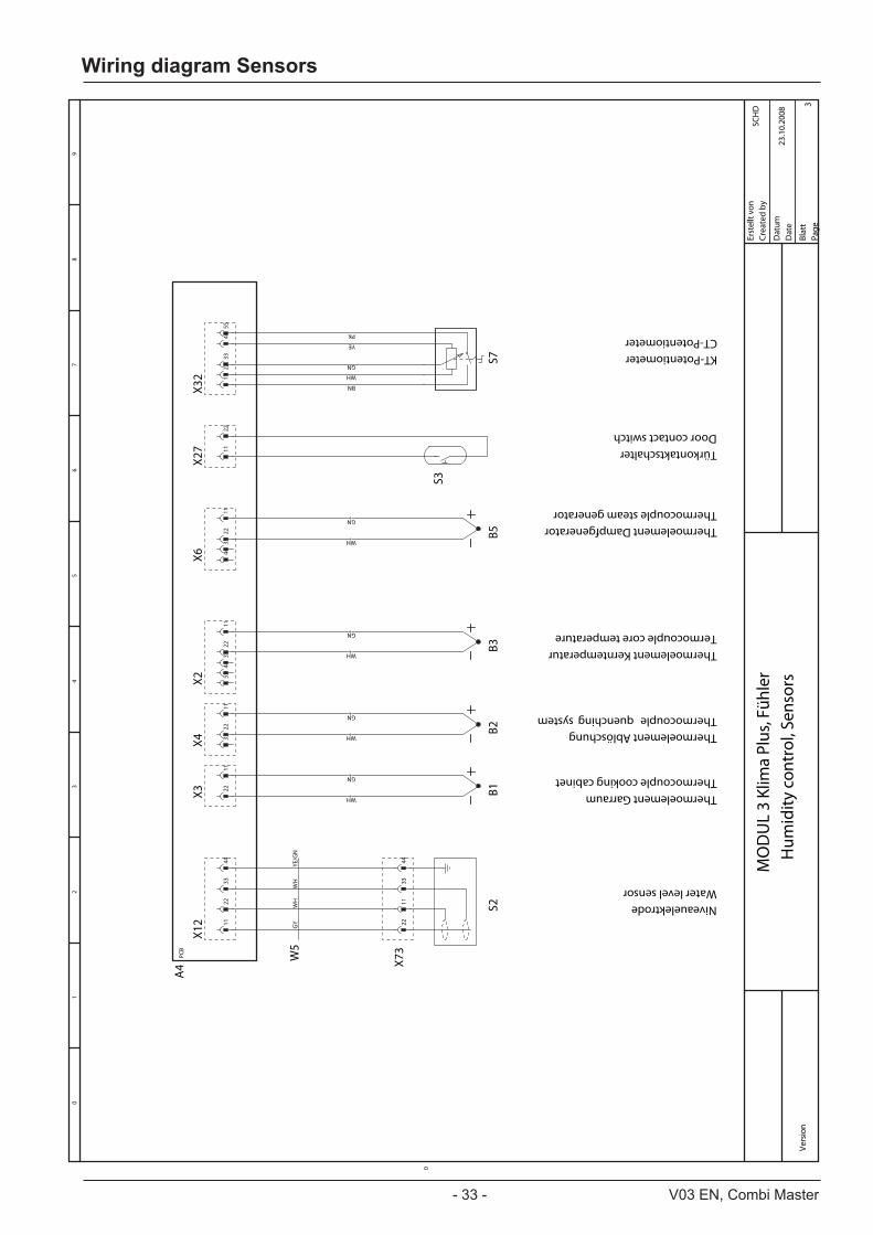
Vers
ion
MO
DU
L 3
Klim
a Pl
us, F
ühle
rH
umid
ity c
ontr
ol, S
enso
rs
Erst
ellt
von
Crea
ted
by
Dat
umD
ate
Blat
tPa
ge
SCH
D 3
23.1
0.20
08
A4
PCB
S2 NiveauelektrodeWater level sensor
W5
GY
WH
WH
YE/G
N
X12 11
X73
22
22 11
33 33
44 44
B1 Thermoelement GarraumThermocouple cooking cabinet
X3 22
WH
11
GN
X4 33
B2 Thermoelement AblöschungThermocouple quenchingsystem
22
WH
11
GN
X2 5544
33
B3 Thermoelement KerntemperaturTermocouple core temperature
22
WH
11
GN
X6 4433
B5
Thermoelement DampfgeneratorThermocouple steam generator
22
WH
11
GN
S3
TürkontaktschalterDoor contact switch
X27 11
22
S7
KT-PotentiometerCT-Potentiometer
X32 11
BN
22
WH
33
GN
44
YE
55
PK
0
98
76
54
32
10
Wiring diagram Sensors

V03 EN, Combi Master - 34 -Combi Master - 34 - - 34 -
Vers
ion
MO
DU
L 4
Was
ser
Wat
er, D
rain
, Cle
anJe
t
Erst
ellt
von
Crea
ted
by
Dat
umD
ate
Blat
tPa
ge
SCH
D 4
23.1
0.20
08
A4
PCB
W3
WH
BUW
HBU
Y1
Magnetventil-FüllenSolenoid valve filling
A1
A2
X19 33
X30
11
11 22
Y2
Magnetventil-AblöschungSolenoid valve guenching system
A1
A244 33
22 44
5566
M4
SC-PumpeSC-pump
M ~
W4
WH
BU
X18 11
X31
11
22 22
3344
0
98
76
54
32
10
Wiring diagram Water

- 35 - V03 EN, Combi Master
Vers
ion
MO
DU
L 6
Sum
mer
, EEP
ROM
Buzz
er, E
EPRO
M
Erst
ellt
von
Crea
ted
by
Dat
umD
ate
Blat
tPa
ge
SCH
D 6
23.1
0.20
08
A4
PCB
X8 11
X47
1
T2 SummerBuzzer
22 2
E1
Externe EEPROM
X50 11
2233
44
0
98
76
54
32
10
Wiring diagram Miscellaneous

V03 EN, Combi Master - 36 -Combi Master - 36 - - 36 -
Wiring diagram Option
Vers
ion
MO
DU
L 7
Opt
ion
Opt
ions
Erst
ellt
von
Crea
ted
by
Dat
umD
ate
Blat
tPa
ge
SCH
D 7
23.1
0.20
08
A4
PCB X2
0O
ptio
n Si
cotr
onic
syst
emO
ptio
n Si
cotr
onic
syst
em
11 1:Frei
2:Frei
3:Nullleiter (d)
4:Gerät EIN (a)
5:Eingang Sicotronic (c)
6:Heizungsanforderung (b)
2233
4455
66
X23
Opt
ion
Dun
stab
zug
Opt
ion
extr
acto
r hoo
d
1122
33
0
98
76
54
32
10

- 37 - V03 EN, Combi Master
V03 EN, Combi Master - 38 -Combi Master - 38 - - 38 -
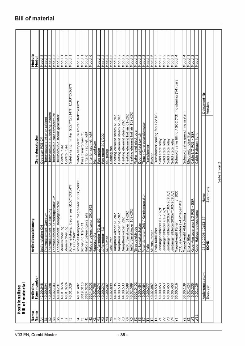
Bill of materialP
osi
tio
nsl
iste
B
ill
of
mate
rial
Nam
e
Nam
e
Art
ikeln
r.
Item
nu
mb
er
Art
ikelb
eze
ich
nu
ng
It
em
desc
rip
tion
M
od
ule
M
od
ul
Änder
ungsd
atum
28.1
0.2
008 1
2:5
3:3
7
Nam
e
Dok
um
ent-
Nr.
Erz
euger
SC
HD
Span
nung
Ver
sion
Sei
te 1
von 2
A4
42.0
0.0
48
Bed
ienpla
tine
CM
O
per
ator
PCB C
M
Modul 8
B1
40.0
0.5
94
Ther
moe
lem
ent
Gar
raum
Ther
moc
ouple
inte
rior
cab
inet
M
odul 3
B2
40.0
0.3
98
Ther
moe
lem
ent
Ablö
schung
Ther
moc
ouple
quen
chin
g s
yste
m
Modul 3
B3
40.0
2.1
03
Ther
moe
lem
ent
Ker
nte
mper
atu
r CM
Ther
moc
ouple
core
tem
per
atu
re
Modul 3
B5
40.0
0.2
91
Ther
moe
lem
ent
Dam
pfg
ener
ator
Ther
moc
ouple
ste
am
gen
erato
r M
odul 3
F14001.0
224
Ste
uer
sich
erung
Contr
ol fu
se
Modul 1
F24001.0
224
Ste
uer
sich
erung
Contr
ol fu
se
Modul 1
F340.0
1.3
29
Sic
her
hei
tste
mp. Beg
renze
r G
157°C
/314°F
E183°C
/360°F
Saf
ety
tem
p.
limiter
G157°C
/314°F
E183°C
/360°F
M
odul 1
F440.0
1.4
82
Sic
her
hei
tste
mper
aturb
egre
nze
r 360°C
/680°F
Saf
ety
tem
per
ature
lim
iter
360°C
/680°F
M
odul 1
F53019.0
113
Sic
her
ung T
rafo
T1
Fuse
tra
nsf
orm
er T
1
Modul 1
H1
3024.0
201
Hal
ogen
bel
euch
tung
alle
In
terior
cabin
et lig
ht
Modul 6
H2
3024.0
201
Hal
ogen
bel
euch
tung 201/2
02
Inte
rior
cabin
et lig
ht
Modul 6
K1
40.0
2.7
66
Hau
pts
chütz
M
ain c
onta
ctor
M1
40.0
0.2
74
Lüft
erm
oto
r TG
u.
SG
Fa
n m
oto
r M
odul 5
M2
40.0
0.2
74
Lüft
erm
oto
r S
G
Fan m
oto
r 201/2
02
Modul 5
M4
44.0
0.2
07
SC-P
um
pe
SC-p
um
p
Modul 4
M5
40.0
2.8
99
Kühllü
fter
Coo
ling f
an
Modul 5
R1
44.0
0.1
95
Dam
pfh
eizk
örp
er 6
1-2
02
Hea
ting e
lem
ent
stea
m 6
1-2
02
Modul 2
R2
44.0
0.5
33
Dam
pfh
eizk
örp
er 6
1-2
02
Hea
ting e
lem
ent
stea
m 6
1-2
02
Modul 2
R3
44.0
0.5
33
Dam
pfh
eizk
örp
er 202
Hea
ting e
lem
ent
stea
m 2
02
Modul 2
R4
40.0
2.5
89
Hei
ßlu
fthei
zkör
per
61-2
02
Hea
ting e
lem
ent
hot
air
61-2
02
Modul 2
R5
40.0
2.5
89
Hei
ßlu
fthei
zkör
per
102-2
02
Hea
ting e
lem
ent
hot
air
102-2
02
Modul 2
S2
3002.0
402
Niv
eauel
ektr
ode
Wat
er lev
el e
lect
rode
Modul 3
S3
40.0
0.4
54
Türk
onta
ktsc
hal
ter
Doo
r co
nta
ct s
witch
M
odul 3
S7
40.0
0.4
64
Pote
ntiom
eter
Zei
t /
Ker
nte
mper
atur
Tim
e /
Core
pote
ntiom
eter
M
odul 3
T1
40.0
0.2
77
Tra
fo
Tra
nsf
orm
er
Modul 1
T2
40.0
2.0
87
Ala
rmsu
mm
er
Buzz
er
Modul 6
T4
40.0
0.5
92
Tra
fo K
ühllü
fter
Tra
nsf
orm
er c
oolin
g fan
12V D
C
Modul 5
V1
40.0
0.4
53
Leis
tungsh
alble
iter
61-2
02/E
Solid
sta
te r
elay
M
odul 2
V2
40.0
0.4
53
Leis
tungsh
alble
iter
61-2
02/E
Solid
sta
te r
elay
M
odul 2
V3
40.0
0.4
53
Leis
tungsh
alble
iter
202Eu*102-2
02U
L/J
Solid
sta
te r
elay
M
odul 2
V4
40.0
0.4
53
Leis
tungsh
alble
iter
202Eu*102-2
02U
L/J
Solid
sta
te r
elay
M
odul 2
Y1
50.0
0.3
16
Mag
net
ventil Fü
llen /
SCC
(Y3)B
esch
wad
en (
Y4)P
fleg
emitte
l Sole
noid
val
ve f
illin
g /
SCC (
Y3)
mois
tenin
g (
Y4)
care
M
odul 4
Y2
50.0
0.1
39
Mag
net
ventil Ablö
schung
Sole
noid
val
ve g
uen
chin
g s
yste
m
Modul 4
Z1
40.0
2.4
24
Ents
törf
ilter
Ele
ctro
nic
nois
e filter
M
odul 1
W1
40.0
0.2
35
Kab
el-A
nst
euer
ung I
/O P
CB -
SSR
Cab
le I
/O P
CB -
SSR
Modul 2
W11
40.0
2.1
29
Kab
el:H
alogen
bel
euch
tung
Cab
le H
alogen
lig
ht
Modul 1

- 39 - V03 EN, Combi Master
Po
siti
on
slis
te
Bil
l o
f m
ate
rial
Nam
e
Nam
e
Art
ikeln
r.
Item
nu
mb
er
Art
ikelb
eze
ich
nu
ng
It
em
desc
rip
tion
M
od
ule
M
od
ul
Änder
ungsd
atum
28.1
0.2
008 1
2:5
3:3
7
Nam
e
D
okum
ent-
Nr.
Erz
euger
SC
HD
Span
nung
Ver
sion
Sei
te 2
von 2
W16
40.0
0.2
39
Kab
el:H
aupts
chütz
- S
SR
Cab
le M
ain c
onta
ctor
- S
SR
Modul 2
W17
40.0
2.4
98
Kab
el:
Ste
uer
stam
m
Cab
le C
ontr
ol Supply
M
odul 1
W25
40.0
2.1
26
Kab
el:S
pan
nungsv
erso
rgung C
M-P
latine
Cab
le
Modul 1
W3
40.0
0.2
20
Kab
el:
Plat
ine
- M
agnet
ventile
Cab
le pcb
- s
ole
noid
val
ve
Modul 4
W4
40.0
0.2
19
Kab
el:
Plat
ine
- SC-P
um
pe
Cab
le p
cb -
SC-p
um
p
Modul 4
W5
40.0
0.2
05
Kab
el:N
ivea
uel
ektr
ode
Cab
le w
ater
lev
el s
enso
r M
odul 3
Bill of material

80.51.104 - V03 EN - RTS/Md 10/2010
RTS Contact Germany
Fax: +49 (0)8191-327397e-mail: [email protected]: http://service.rational-online.com
Service Parts:Fax: +49 (0)8191-327408e-mail: [email protected]
Chef Line:Phone: +49 (0)8191-327300
Please note that any technical information concerning Rational products must NOT be forwarded to any third party.