Traffic Signal Inspection Pocket Guide - PennDOT Home 669.pdf · Traffic Operation Section ....
53
Traffic Signal Inspection Pocket Guide Bureau of Maintenance and Operations Traffic Operation Section Traffic Signal and Operational Analysis PUB 669 (3-12)
-
Upload
duongxuyen -
Category
Documents
-
view
232 -
download
3
Transcript of Traffic Signal Inspection Pocket Guide - PennDOT Home 669.pdf · Traffic Operation Section ....

Traffic Signal
Inspection
Pocket Guide
Bureau of Maintenance and Operations
Traffic Operation Section
Traffic Signal and Operational Analysis
PUB 669 (3-12)

i
TRAFFIC SIGNAL INSPECTION POCKET GUIDE
TABLE OF CONTENTS
1.0 Introduc on 1.1 Purpose and Limits of Pocket Guide 1.2 Applicable Publica ons and Sec ons of the 408 1.3 Responsibili es of the Inspector 1.4 Responsibili es of the District Traffic Unit 1.5 Districts and Signal Supervisor Phone Numbers
2.0 General 2.1 Principles 2.2 Submi al and Approvals 2.3 Miscellaneous Requirements and Informa on
3.0 Electrical Service Connec ons 3.1 Electrical Service Type A (Wood Poles) 3.2 Electrical Service Type B (Steel Poles) 3.3 Electrical Service Type C (Underground) 3.4 Meter Socket and Disconnect (All Service Types)
4.0 Traffic Signal Structural Supports 4.1 Founda ons 4.2 Traffic Signal Supports 4.3 Mast Arms 4.4 Strain Pole 4.5 Pedestal Poles 4.6 Pedestrian Pushbu on Pole 4.7 Wood Poles
5.0 Traffic Signal Subsurface Facili es 5.1 Trench and Backfill 5.2 Conduit 5.3 Junc on Boxes
6.0 Controllers 6.1 Approval Lis ngs 6.2 Controller Founda ons 6.3 Controller Cabinets 6.4 Manual Test Control 6.5 Grounding Assemblies 6.6 Control Equipment and Wiring Installa on 6.7 Programming and Timing
1
2
3
4
5
6
7
8
9
10
11
12
1 1 1 2 2 3
4 4 4 5
7 7 9
10 10
11 11 12 14 16 18 18
19 19 21 22
23 23 23 25 26 27 28 31
ii
7.0 Signal Indica ons 7.1 Vehicular 7.2 Pedestrian 7.3 Preemp on Fail Safe Indica ons
8.0 Electrical Distribu on 8.1 Grounding 8.2 Signal Cable, Wiring and ID Tags 8.3 Wiring Diagrams 8.4 Tes ng
9.0 Detec on 9.1 Vehicular
9.1.1 Inductance Loops 9.1.2 Video Detec on 9.1.3 Microwave Radar, Digital Wave Radar, Magne c and Magnetometer Detec on Systems
9.2 Pedestrian Pushbu ons 9.3 Preemp on Systems 9.4 Other Preemp on Systems
10.0 Pavement Markings and Signs 10.1 Pavement Marking Loca ons 10.2 Placement of Pavement Marking Material 10.3 Sign Types and Loca ons
11.0 Traffic Signal Systems 11.1 Equipment 11.2 So ware 11.3 Training 11.4 Communica ons 11.5 Tes ng
12.0 Final Inspec on and Tes ng 12.1 Inspec on Turn‐on Procedures and Flashing Opera ons 12.2 30 Day Test 12.3 180 Day Equipment Guarantee Period 12.4 Systems Tes ng
1
2
3
4
5
6
7
8
9
10
11
12
32 32 33 34
35 35 35 36 36
37 37 37 40 40
41 43
44 44 44 45
46 46 46 46 46 48
49 49 49 49 50
1
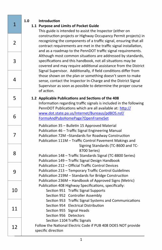
1.0 Introduc on 1.1 Purpose and Limits of Pocket Guide
This guide is intended to assist the Inspector (either on construc on projects or Highway Occupancy Permit projects) in recognizing the components of a traffic signal, ensuring that all contract requirements are met in the traffic signal installa on, and as a roadmap to the PennDOT traffic signal requirements. Although most common situa ons are addressed by standards, specifica ons and this handbook, not all situa ons may be covered and may require addi onal assistance from the District Signal Supervisor. Addi onally, if field condi ons differ from those shown on the plan or something doesn’t seem to make sense, contact the Inspector In‐Charge and the District Signal Supervisor as soon as possible to determine the proper course of ac on.
1.2 Applicable Publica ons and Sec ons of the 408 Informa on regarding traffic signals is included in the following PennDOT Publica ons which are all available at: h p://www.dot.state.pa.us/Internet/Bureaus/pdBOS.nsf/FormsAndPubsHomePage?OpenFrameSet
Publica on 35 – Bulle n 15 Approved Material Publica on 46 – Traffic Signal Engineering Manual Publica on 72M –Standards for Roadway Construc on Publica on 111M – Traffic Control Pavement Makings and
Signing Standards (TC‐8600 and TC‐8700 Series)
Publica on 148 – Traffic Standards Signal (TC‐8800 Series) Publica on 149 – Traffic Signal Design Handbook Publica on 212 – Official Traffic Control Devices Publica on 213 – Temporary Traffic Control Guidelines Publica on 219M – Standards for Bridge Construc on Publica on 236M – Handbook of Approved Signs (Metric) Publica on 408 Highway Specifica ons, specifically:
Sec on 951 Traffic Signal Supports Sec on 952 Controller Assembly Sec on 953 Traffic Signal Systems and Communica ons Sec on 954 Electrical Distribu on Sec on 955 Signal Heads Sec on 956 Detectors Sec on 1104 Traffic Signals
Follow the Na onal Electric Code if PUB 408 DOES NOT provide specific direc on
1
2
3
4
5
6
7
8
9
10
11
12
2
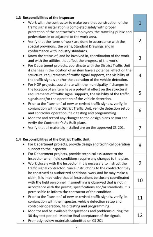
1.3 Responsibili es of the Inspector Work with the contractor to make sure that construc on of the
traffic signal installa on is completed safely with proper protec on of the contractor’s employees, the traveling public and pedestrians in or adjacent to the work area.
Verify that the items of work are done in accordance with the special provisions, the plans, Standard Drawings and in conformance with industry standards.
Know the status of, and be involved in, coordina on of the work and with the u li es that affect the progress of the work.
For Department projects, coordinate with the District Traffic Unit if changes in the loca on of an item have a poten al effect on the structural requirements of traffic signal supports, the visibility of the traffic signals and/or the opera on of the vehicle detec on.
For HOP projects, coordinate with the municipality if changes in the loca on of an item have a poten al effect on the structural requirements of traffic signal supports, the visibility of the traffic signals and/or the opera on of the vehicle detec on.
Prior to the “turn‐on” of new or revised traffic signals, verify, in conjunc on with the District Traffic Unit, vehicle detec on setup and controller opera on, field tes ng and programming.
Monitor and record any changes to the design plans so you can verify the Contractor’s As‐Built plans.
Verify that all materials installed are on the approved CS‐201.
1.4 Responsibili es of the District Traffic Unit For Department projects, provide design and technical opera on
support to the Inspector. For Department projects, provide technical assistance to the
Inspector when field condi ons require any changes to the plan. Work closely with the Inspector if it is necessary to instruct the
traffic signal contractor. Since instruc ons to the contractor may be construed as authorized addi onal work and he may make a claim, it is impera ve that all instruc ons be closely coordinated with the field personnel. If something is observed that is not in accordance with the permit, specifica ons and/or standards, it is permissible to inform the contractor of the condi on.
Prior to the “turn‐on” of new or revised traffic signals, verify, in conjunc on with the Inspector, vehicle detec on setup and controller opera on, field tes ng and programming.
Monitor and be available for ques ons and problems during the 30 day test period. Monitor final acceptance of the signals.
Promptly review materials submi ed on CS‐201
1
2
3
4
5
6
7
8
9
10
11
12
1
1.0 Introduc on 1.1 Purpose and Limits of Pocket Guide
This guide is intended to assist the Inspector (either on construc on projects or Highway Occupancy Permit projects) in recognizing the components of a traffic signal, ensuring that all contract requirements are met in the traffic signal installa on, and as a roadmap to the PennDOT traffic signal requirements. Although most common situa ons are addressed by standards, specifica ons and this handbook, not all situa ons may be covered and may require addi onal assistance from the District Signal Supervisor. Addi onally, if field condi ons differ from those shown on the plan or something doesn’t seem to make sense, contact the Inspector In‐Charge and the District Signal Supervisor as soon as possible to determine the proper course of ac on.
1.2 Applicable Publica ons and Sec ons of the 408 Informa on regarding traffic signals is included in the following PennDOT Publica ons which are all available at: h p://www.dot.state.pa.us/Internet/Bureaus/pdBOS.nsf/FormsAndPubsHomePage?OpenFrameSet
Publica on 35 – Bulle n 15 Approved Material Publica on 46 – Traffic Signal Engineering Manual Publica on 72M –Standards for Roadway Construc on Publica on 111M – Traffic Control Pavement Makings and
Signing Standards (TC‐8600 and TC‐8700 Series)
Publica on 148 – Traffic Standards Signal (TC‐8800 Series) Publica on 149 – Traffic Signal Design Handbook Publica on 212 – Official Traffic Control Devices Publica on 213 – Temporary Traffic Control Guidelines Publica on 219M – Standards for Bridge Construc on Publica on 236M – Handbook of Approved Signs (Metric) Publica on 408 Highway Specifica ons, specifically:
Sec on 951 Traffic Signal Supports Sec on 952 Controller Assembly Sec on 953 Traffic Signal Systems and Communica ons Sec on 954 Electrical Distribu on Sec on 955 Signal Heads Sec on 956 Detectors Sec on 1104 Traffic Signals
Follow the Na onal Electric Code if PUB 408 DOES NOT provide specific direc on
1
2
3
4
5
6
7
8
9
10
11
12
2
1.3 Responsibili es of the Inspector Work with the contractor to make sure that construc on of the
traffic signal installa on is completed safely with proper protec on of the contractor’s employees, the traveling public and pedestrians in or adjacent to the work area.
Verify that the items of work are done in accordance with the special provisions, the plans, Standard Drawings and in conformance with industry standards.
Know the status of, and be involved in, coordina on of the work and with the u li es that affect the progress of the work.
For Department projects, coordinate with the District Traffic Unit if changes in the loca on of an item have a poten al effect on the structural requirements of traffic signal supports, the visibility of the traffic signals and/or the opera on of the vehicle detec on.
For HOP projects, coordinate with the municipality if changes in the loca on of an item have a poten al effect on the structural requirements of traffic signal supports, the visibility of the traffic signals and/or the opera on of the vehicle detec on.
Prior to the “turn‐on” of new or revised traffic signals, verify, in conjunc on with the District Traffic Unit, vehicle detec on setup and controller opera on, field tes ng and programming.
Monitor and record any changes to the design plans so you can verify the Contractor’s As‐Built plans.
Verify that all materials installed are on the approved CS‐201.
1.4 Responsibili es of the District Traffic Unit For Department projects, provide design and technical opera on
support to the Inspector. For Department projects, provide technical assistance to the
Inspector when field condi ons require any changes to the plan. Work closely with the Inspector if it is necessary to instruct the
traffic signal contractor. Since instruc ons to the contractor may be construed as authorized addi onal work and he may make a claim, it is impera ve that all instruc ons be closely coordinated with the field personnel. If something is observed that is not in accordance with the permit, specifica ons and/or standards, it is permissible to inform the contractor of the condi on.
Prior to the “turn‐on” of new or revised traffic signals, verify, in conjunc on with the Inspector, vehicle detec on setup and controller opera on, field tes ng and programming.
Monitor and be available for ques ons and problems during the 30 day test period. Monitor final acceptance of the signals.
Promptly review materials submi ed on CS‐201
1
2
3
4
5
6
7
8
9
10
11
12
3
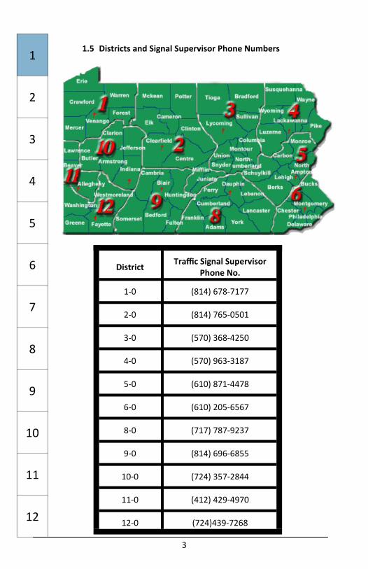
1.5 Districts and Signal Supervisor Phone Numbers
District Traffic Signal Supervisor Phone No.
1‐0 (814) 678‐7177
2‐0 (814) 765‐0501
3‐0 (570) 368‐4250
4‐0 (570) 963‐3187
5‐0 (610) 871‐4478
6‐0 (610) 205‐6567
8‐0 (717) 787‐9237
9‐0 (814) 696‐6855
10‐0 (724) 357‐2844
11‐0 (412) 429‐4970
12‐0 (724)439‐7268
1
2
3
4
5
6
7
8
9
10
11
12
4
2.0 General 2.1 Principles 1. Closely adhere to the contract documents. Any devia on from
the drawings should only be done a er consulta on with the District Signal Supervisor.
2. Work with the contractor to ensure the safe and efficient flow of traffic during construc on.
3. Take into account the future opera onal needs and municipal maintenance of the traffic signal.
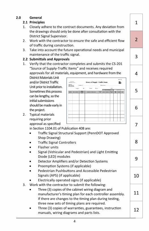
2.2 Submi als and Approvals 1. Verify that the contractor completes and submits the CS‐201
“Source of Supply‐Traffic Items” and receives required approvals for all materials, equipment, and hardware from the District Materials Unit and/or District Traffic Unit prior to installa on. Some mes this process can be lengthy, so the ini al submissions should be made early in the project.
2. Typical materials requiring prior approval as specified in Sec on 1104.01 of Publica on 408 are: Traffic Signal Structural Support (PennDOT Approved
Shop Drawing) Traffic Signal Controllers Flasher units Signal (Vehicular and Pedestrian) and Light Emi ng
Diode (LED) modules Detector Amplifiers and/or Detec on Systems Preemp on Systems (if applicable) Pedestrian Pushbu ons and Accessible Pedestrian
Signals (APS) (if applicable) Electrically operated signs (if applicable)
3. Work with the contractor to submit the following: Three (3) copies of the cabinet wiring diagram and
manufacturer's ming plan for each controller assembly. If there are changes to the ming plan during tes ng, three new sets of ming plans are required.
Three (3) copies of warran es, guarantees, instruc on manuals, wiring diagrams and parts lists.
1
2
3
4
5
6
7
8
9
10
11
12
3
1.5 Districts and Signal Supervisor Phone Numbers
District Traffic Signal Supervisor Phone No.
1‐0 (814) 678‐7177
2‐0 (814) 765‐0501
3‐0 (570) 368‐4250
4‐0 (570) 963‐3187
5‐0 (610) 871‐4478
6‐0 (610) 205‐6567
8‐0 (717) 787‐9237
9‐0 (814) 696‐6855
10‐0 (724) 357‐2844
11‐0 (412) 429‐4970
12‐0 (724)439‐7268
1
2
3
4
5
6
7
8
9
10
11
12
4
2.0 General 2.1 Principles 1. Closely adhere to the contract documents. Any devia on from
the drawings should only be done a er consulta on with the District Signal Supervisor.
2. Work with the contractor to ensure the safe and efficient flow of traffic during construc on.
3. Take into account the future opera onal needs and municipal maintenance of the traffic signal.
2.2 Submi als and Approvals 1. Verify that the contractor completes and submits the CS‐201
“Source of Supply‐Traffic Items” and receives required approvals for all materials, equipment, and hardware from the District Materials Unit and/or District Traffic Unit prior to installa on. Some mes this process can be lengthy, so the ini al submissions should be made early in the project.
2. Typical materials requiring prior approval as specified in Sec on 1104.01 of Publica on 408 are: Traffic Signal Structural Support (PennDOT Approved
Shop Drawing) Traffic Signal Controllers Flasher units Signal (Vehicular and Pedestrian) and Light Emi ng
Diode (LED) modules Detector Amplifiers and/or Detec on Systems Preemp on Systems (if applicable) Pedestrian Pushbu ons and Accessible Pedestrian
Signals (APS) (if applicable) Electrically operated signs (if applicable)
3. Work with the contractor to submit the following: Three (3) copies of the cabinet wiring diagram and
manufacturer's ming plan for each controller assembly. If there are changes to the ming plan during tes ng, three new sets of ming plans are required.
Three (3) copies of warran es, guarantees, instruc on manuals, wiring diagrams and parts lists.
1
2
3
4
5
6
7
8
9
10
11
12

5
2.2 Submi als and Approvals (Con nued) Controller Assembly Instruc on Manuals to be placed in each
controller cabinet. Two (2) keys for each controller cabinet lock (Two for the
Number 2 cabinet lock and two police keys). Shop Drawings and calcula ons for approval for all traffic signal
supports on the project. The shop drawings are to be stamped by a Professional Engineer registered in Pennsylvania.
2.3 Miscellaneous Requirements and Informa on 1. Verify that the contractor permanently marks the following
materials with the manufacturer's name, serial number and model or part number: Controller Unit Confl ict Monitor Flashers Re l a y s Load Switches Time‐base Units, including GPS units Detector Amplifiers Detector Power Supplies Detec on Systems & equipment Interfaces Modems Emergency Vehicle Preemp on Units UPS System Verify that the contractor maintains removed controller assemblies as a unit and stores the material at the project site in a secure loca on. For further informa on, refer to PUB 408, Sec on 1104.01
2. Contact the District Signal Supervisor at least 7 calendar days before marking pole loca ons so it may be determined if a Traffic Unit Representa ve should be present.
3. Verify that, a er the new installa on is opera onal, the contractor removes all exis ng traffic signal supports (including those with traffic signals), flashing warning devices, and lane control signs and signal equipment, unless otherwise directed. All equipment removed shall be returned to the municipal traffic signal owner. The contractor should maintain removed controller assemblies as a unit and the material should be stored at the project site. The contractor should prepare a lis ng of the equipment for the municipal owner, make arrangements to deliver the equipment to the municipal storage area and receive a wri en receipt acknowledging receipt of the equipment. It is the contractor’s responsibility to coordinate this transfer.
1
2
3
4
5
6
7
8
9
10
11
12
6
2.3 Miscellaneous Requirements and Informa on (Con nued) 4. Document any damage to the equipment before its removal. The
contractor is responsible for equipment damage during removal or storage. The contractor should provide no fica on to the inspector that the equipment was properly transferred to the municipal signal owner.
5. Unless otherwise noted, underground conduit, conductors, and detectors not interfering with new construc on can be le in place. Founda ons and junc on boxes that are to be abandoned and are located outside of the shoulder area should be removed to 1 foot below final grade. Check with the Inspector In‐Charge to determine what can be le in place. The contractor is responsible for disposal of the removed materials and to properly fill, compact, and landscape the resul ng hole, including adding topsoil if necessary.
6. If there are any ques ons concerning devia on from Publica ons 408 and 148, the special provisions and the contract plans, it is cri cal that the Inspector contact the Inspector In‐Charge and the District Signal Supervisor.
7. Exis ng traffic signals are to remain and con nue their current opera on un l the new signal is operable, absent any provisions to the contrary. If an exis ng traffic signal must be turned off or turned to flashing opera ons, work with the contractor to provide flaggers or police control and obtain approval from the District Signal Supervisor and municipal signal owner prior to modifying the exis ng opera on.
8. If any vegeta on is obstruc ng the visibility of traffic signal indica ons (vehicular and pedestrian) or signs, work with the contractor to request and obtain approval to remove the obstruc ons.
9. Verify that the contractor iden fies possible u lity conflicts early. Contact the District U lity Coordinator and District Signal Supervisor to determine the correc ve ac on if a u lity conflict exists.
10. Verify that conflic ng signs are bagged immediately a er the signal is turned on. If the signs are to be removed, they should be removed as soon as possible.
11. Obtain from the contractor the name and telephone number of the person to be no fied in the event of failures or malfunc ons during the guarantee period.
1
2
3
4
5
6
7
8
9
10
11
12

5
2.2 Submi als and Approvals (Con nued) Controller Assembly Instruc on Manuals to be placed in each
controller cabinet. Two (2) keys for each controller cabinet lock (Two for the
Number 2 cabinet lock and two police keys). Shop Drawings and calcula ons for approval for all traffic signal
supports on the project. The shop drawings are to be stamped by a Professional Engineer registered in Pennsylvania.
2.3 Miscellaneous Requirements and Informa on 1. Verify that the contractor permanently marks the following
materials with the manufacturer's name, serial number and model or part number: Controller Unit Confl ict Monitor Flashers Re l a y s Load Switches Time‐base Units, including GPS units Detector Amplifiers Detector Power Supplies Detec on Systems & equipment Interfaces Modems Emergency Vehicle Preemp on Units UPS System Verify that the contractor maintains removed controller assemblies as a unit and stores the material at the project site in a secure loca on. For further informa on, refer to PUB 408, Sec on 1104.01
2. Contact the District Signal Supervisor at least 7 calendar days before marking pole loca ons so it may be determined if a Traffic Unit Representa ve should be present.
3. Verify that, a er the new installa on is opera onal, the contractor removes all exis ng traffic signal supports (including those with traffic signals), flashing warning devices, and lane control signs and signal equipment, unless otherwise directed. All equipment removed shall be returned to the municipal traffic signal owner. The contractor should maintain removed controller assemblies as a unit and the material should be stored at the project site. The contractor should prepare a lis ng of the equipment for the municipal owner, make arrangements to deliver the equipment to the municipal storage area and receive a wri en receipt acknowledging receipt of the equipment. It is the contractor’s responsibility to coordinate this transfer.
1
2
3
4
5
6
7
8
9
10
11
12
6
2.3 Miscellaneous Requirements and Informa on (Con nued) 4. Document any damage to the equipment before its removal. The
contractor is responsible for equipment damage during removal or storage. The contractor should provide no fica on to the inspector that the equipment was properly transferred to the municipal signal owner.
5. Unless otherwise noted, underground conduit, conductors, and detectors not interfering with new construc on can be le in place. Founda ons and junc on boxes that are to be abandoned and are located outside of the shoulder area should be removed to 1 foot below final grade. Check with the Inspector In‐Charge to determine what can be le in place. The contractor is responsible for disposal of the removed materials and to properly fill, compact, and landscape the resul ng hole, including adding topsoil if necessary.
6. If there are any ques ons concerning devia on from Publica ons 408 and 148, the special provisions and the contract plans, it is cri cal that the Inspector contact the Inspector In‐Charge and the District Signal Supervisor.
7. Exis ng traffic signals are to remain and con nue their current opera on un l the new signal is operable, absent any provisions to the contrary. If an exis ng traffic signal must be turned off or turned to flashing opera ons, work with the contractor to provide flaggers or police control and obtain approval from the District Signal Supervisor and municipal signal owner prior to modifying the exis ng opera on.
8. If any vegeta on is obstruc ng the visibility of traffic signal indica ons (vehicular and pedestrian) or signs, work with the contractor to request and obtain approval to remove the obstruc ons.
9. Verify that the contractor iden fies possible u lity conflicts early. Contact the District U lity Coordinator and District Signal Supervisor to determine the correc ve ac on if a u lity conflict exists.
10. Verify that conflic ng signs are bagged immediately a er the signal is turned on. If the signs are to be removed, they should be removed as soon as possible.
11. Obtain from the contractor the name and telephone number of the person to be no fied in the event of failures or malfunc ons during the guarantee period.
1
2
3
4
5
6
7
8
9
10
11
12
7
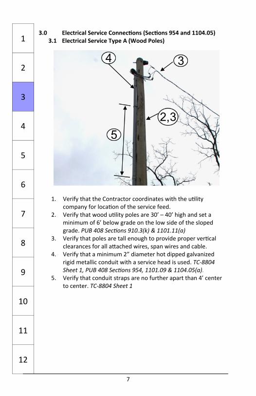
3.0 Electrical Service Connec ons (Sec ons 954 and 1104.05) 3.1 Electrical Service Type A (Wood Poles)
1. Verify that the Contractor coordinates with the u lity company for loca on of the service feed.
2. Verify that wood u lity poles are 30’ – 40’ high and set a minimum of 6’ below grade on the low side of the sloped grade. PUB 408 Sec ons 910.3(k) & 1101.11(a)
3. Verify that poles are tall enough to provide proper ver cal clearances for all a ached wires, span wires and cable.
4. Verify that a minimum 2” diameter hot dipped galvanized rigid metallic conduit with a service head is used. TC‐8804 Sheet 1, PUB 408 Sec ons 954, 1101.09 & 1104.05(a).
5. Verify that conduit straps are no further apart than 4’ center to center. TC‐8804 Sheet 1
1
2
3
4
5
6
7
8
9
10
11
12
8
3.1 Electrical Service Type A (Wood Poles (Con nued) 6. Verify that the Contractor coordinates the meter type and
socket with the u lity company PUB 408 Sec on 1104.05(d)3)
7. Verify that a service disconnect without an external han‐dle is included. TC‐8804, PUB 408 Sec ons 954 & 1104.05(d)
8. Verify that a minimum 2” diameter conduit goes between the service disconnect and the controller to carry service conductors.
9. Verify that there is a ¾” minimum diameter conduit with a minimum #4 AWG grounding conductor connected to the ground rod and to ground bus in the service disconnect.
1
2
3
4
5
6
7
8
9
10
11
12

7
3.0 Electrical Service Connec ons (Sec ons 954 and 1104.05) 3.1 Electrical Service Type A (Wood Poles)
1. Verify that the Contractor coordinates with the u lity company for loca on of the service feed.
2. Verify that wood u lity poles are 30’ – 40’ high and set a minimum of 6’ below grade on the low side of the sloped grade. PUB 408 Sec ons 910.3(k) & 1101.11(a)
3. Verify that poles are tall enough to provide proper ver cal clearances for all a ached wires, span wires and cable.
4. Verify that a minimum 2” diameter hot dipped galvanized rigid metallic conduit with a service head is used. TC‐8804 Sheet 1, PUB 408 Sec ons 954, 1101.09 & 1104.05(a).
5. Verify that conduit straps are no further apart than 4’ center to center. TC‐8804 Sheet 1
1
2
3
4
5
6
7
8
9
10
11
12
8
3.1 Electrical Service Type A (Wood Poles (Con nued) 6. Verify that the Contractor coordinates the meter type and
socket with the u lity company PUB 408 Sec on 1104.05(d)3)
7. Verify that a service disconnect without an external han‐dle is included. TC‐8804, PUB 408 Sec ons 954 & 1104.05(d)
8. Verify that a minimum 2” diameter conduit goes between the service disconnect and the controller to carry service conductors.
9. Verify that there is a ¾” minimum diameter conduit with a minimum #4 AWG grounding conductor connected to the ground rod and to ground bus in the service disconnect.
1
2
3
4
5
6
7
8
9
10
11
12

9
3.2 Electrical Service Type B (Steel Poles) 1. Verify that Contractor coordinates with the u lity company for
loca on of the service feed. 2. Verify that a minimum 2” diameter hot dipped galvanized rigid
metallic conduit with service head is used for service unless otherwise required by the u lity company. TC‐8804 Sheet 1, PUB 408 Sec on 954 & 1101.09
3. Verify that conduit straps are no further apart than 4’ center to center. TC‐8804 Sheet 1
4. Verify that the Contractor coordinates the meter type and socket with the u lity company. PUB 408 Sec on 1104.05(d)3
5. Verify that a service disconnect without an external handle is included. TC 8804 Sheet 1, PUB 408 Sec ons 954 & 1104.05(d)
6. Verify that there is a 1” minimum diameter conduit in pole founda on with #4 AWG minimum grounding conductor to ground rod in earth adjacent to pole founda on.
7. Verify that the minimum clearance as indicated in Pub 149 is obtained. TC‐8801 sheet 1
8. Verify that the electrical u lity inspec on occurred or was waived by the u lity company. PUB 408, Sec on 954.3(f))
9. Verify that non‐shrink mortar is used beneath the base plate in paved areas and metal screening is placed beneath the base plate in unpaved areas. Pub. 408 sec. 951.3(c)) TC‐8801
10. Clearances vary by facility, voltage and owner. If there is a ques on of appropriate clearance, contact the District U lity Administrator
1
2
3
4
5
6
7
8
9
10
11
12
5
9
7
4
2
10
3.3 Electrical Service, Type C (Installed on base mounted controller cabinet)
1. Verify that the Contractor coordinates the meter type and socket with the u lity company. PUB 408 Sec on 1104.05(d)3)
2. Verify that a minimum 2” diameter hot dipped galvanized rigid metallic conduit and fi ngs are used for service unless otherwise required by the U lity. TC‐8804
3. Verify that a galvanized rigid steel 2” conduit is used between the meter and the disconnect enclosure. TC‐8804
4. Verify that a galvanized rigid steel 2” conduit and fi ngs are used between the disconnect enclosure and the controller cabinet. TC‐8804
3.4 Meter Socket and Disconnect (All Service Types) 1. Verify that the Contractor coordinates the meter type and
socket with the u lity company. TC‐8804 and PUB 408 Sec on 1104.05(d)3
2. Verify that service conductors to the u lity company connec on point are #2 AWG minimum and, if required by the u lity company, the correct color. PUB 408 Sec on 1104.05(b)2 & TC‐8804
3. Verify that the power line surge protector is in accordance with PUB 408 Sec on 1104.05(d)4.e & TC‐8804 Sheet 1
4. Verify that the service disconnect is rated at a minimum of 100 amps or as required by power company. TC‐8804
5. Verify that ungrounded conductors, grounded conductors, and equipment grounding conductors to traffic controller are a minimum of #8 AWG. TC‐8804
6. Verify that a galvanized steel, stainless steel, or aluminum service enclosure with hinged door and provisions for a padlock conforming to NEMA Standard Type 3R, 3S, or 4 is provided. Pub 408 Sec on 1104.05(d)4.a
7. Verify that the ground wire is either bare or green insulated #8 AWG minimum. PUB 408 Sec on 1104.05(b)3
8. Verify that the grounding electrode from service is connected to the grounding lug inside the enclosure with a #4 AWG conductor. PUB 408 Sec on 1104.05(f) & TC‐8804
1
2
3
4
5
6
7
8
9
10
11
12

9
3.2 Electrical Service Type B (Steel Poles) 1. Verify that Contractor coordinates with the u lity company for
loca on of the service feed. 2. Verify that a minimum 2” diameter hot dipped galvanized rigid
metallic conduit with service head is used for service unless otherwise required by the u lity company. TC‐8804 Sheet 1, PUB 408 Sec on 954 & 1101.09
3. Verify that conduit straps are no further apart than 4’ center to center. TC‐8804 Sheet 1
4. Verify that the Contractor coordinates the meter type and socket with the u lity company. PUB 408 Sec on 1104.05(d)3
5. Verify that a service disconnect without an external handle is included. TC 8804 Sheet 1, PUB 408 Sec ons 954 & 1104.05(d)
6. Verify that there is a 1” minimum diameter conduit in pole founda on with #4 AWG minimum grounding conductor to ground rod in earth adjacent to pole founda on.
7. Verify that the minimum clearance as indicated in Pub 149 is obtained. TC‐8801 sheet 1
8. Verify that the electrical u lity inspec on occurred or was waived by the u lity company. PUB 408, Sec on 954.3(f))
9. Verify that non‐shrink mortar is used beneath the base plate in paved areas and metal screening is placed beneath the base plate in unpaved areas. Pub. 408 sec. 951.3(c)) TC‐8801
10. Clearances vary by facility, voltage and owner. If there is a ques on of appropriate clearance, contact the District U lity Administrator
1
2
3
4
5
6
7
8
9
10
11
12
5
9
7
4
2
10
3.3 Electrical Service, Type C (Installed on base mounted controller cabinet)
1. Verify that the Contractor coordinates the meter type and socket with the u lity company. PUB 408 Sec on 1104.05(d)3)
2. Verify that a minimum 2” diameter hot dipped galvanized rigid metallic conduit and fi ngs are used for service unless otherwise required by the U lity. TC‐8804
3. Verify that a galvanized rigid steel 2” conduit is used between the meter and the disconnect enclosure. TC‐8804
4. Verify that a galvanized rigid steel 2” conduit and fi ngs are used between the disconnect enclosure and the controller cabinet. TC‐8804
3.4 Meter Socket and Disconnect (All Service Types) 1. Verify that the Contractor coordinates the meter type and
socket with the u lity company. TC‐8804 and PUB 408 Sec on 1104.05(d)3
2. Verify that service conductors to the u lity company connec on point are #2 AWG minimum and, if required by the u lity company, the correct color. PUB 408 Sec on 1104.05(b)2 & TC‐8804
3. Verify that the power line surge protector is in accordance with PUB 408 Sec on 1104.05(d)4.e & TC‐8804 Sheet 1
4. Verify that the service disconnect is rated at a minimum of 100 amps or as required by power company. TC‐8804
5. Verify that ungrounded conductors, grounded conductors, and equipment grounding conductors to traffic controller are a minimum of #8 AWG. TC‐8804
6. Verify that a galvanized steel, stainless steel, or aluminum service enclosure with hinged door and provisions for a padlock conforming to NEMA Standard Type 3R, 3S, or 4 is provided. Pub 408 Sec on 1104.05(d)4.a
7. Verify that the ground wire is either bare or green insulated #8 AWG minimum. PUB 408 Sec on 1104.05(b)3
8. Verify that the grounding electrode from service is connected to the grounding lug inside the enclosure with a #4 AWG conductor. PUB 408 Sec on 1104.05(f) & TC‐8804
1
2
3
4
5
6
7
8
9
10
11
12
11
4.0 Traffic Signal Structural Supports (PUB 408 Sec ons 951 and 1104.02)
4.1 Founda ons 1. Field‐verify that traffic signal supports are located in
accordance with the approved plans and that the minimum clearance as indicated in Pub 149 is obtained. TC‐8801 sheet 1
2. Verify that the "Pennsylvania One Call System (#811)" no fica on was completed by the contractor and all acceptable clearances were obtained.
3. Contact the District Signal Supervisor to resolve any conflicts between exis ng u li es and the plan loca on of any support founda on.
4. Verify that the eleva ons for the traffic signal support founda ons ensuring proper clearance above the roadway to the bo om of signal heads and/or signs and/or tether wire. The signal contractor is responsible for coordina on with the prime contractor in determining pole founda on eleva ons. Changes to grades shown on the drawings must be factored into the signal contractor's determina on of sha height and founda on eleva ons. See TC 8801
5. Verify founda on type, depth and rebar configura on in TC‐8801, which are determined by the following: Approved Traffic Signal Support‐mast arm length. Approved Traffic Signal Support‐Strain Pole‐design
tension and sha length. 6. For a founda on within a sidewalk area, verify that the top of
the founda on will be flush with the final finished surface. 7. For a founda on outside a paved sidewalk, verify that the top
of the founda on will be at least 6“above the surrounding surface.
8. Verify that anchor bolts are clean, protected and placed at the same eleva on. Verify that the bolt projec on is sufficient to rake the support properly.
9. Verify that the Contractor has used the proper length anchor bolt considering the required embedment length and required projec on as shown on TC‐8801
10. Verify that all conduits are in place and will be able to fit within the footprint of the pole when it is set. The conduits must have 24 inches of cover to the top of subbase when they exit the founda on.
1
2
3
4
5
6
7
8
9
10
11
12
12
4.2 Traffic Signal Supports 1. Verify that traffic signal supports were inspected in the
fabrica on plant in accordance with PUB 408 Sec on 1104.01. 2. Verify that base plate anchor bolts, nuts and washers are in‐
stalled and ghtened in accordance with PUB 408 Sec on 1104.Verify that the distance between the bo om of each leveling nut and the concrete founda on is less than the bolt diameter.
3. Verify that the center line of the hand hole is 18” above the base plate. TC‐8801
4. Verify that the minimum area of hand hole is 25 square inches with a minimum unobstructed width of 3.5”. TC‐8801
5. Verify that the opening in the hand hole frame is 7” in height, 3 1/2” in width, cut from 3” thick plate and protrudes from pole ¾” minimum. TC‐8801 sheet 10
1
2
3
4
5
6
7
8
9
10
11
12
3 2

11
4.0 Traffic Signal Structural Supports (PUB 408 Sec ons 951 and 1104.02)
4.1 Founda ons 1. Field‐verify that traffic signal supports are located in
accordance with the approved plans and that the minimum clearance as indicated in Pub 149 is obtained. TC‐8801 sheet 1
2. Verify that the "Pennsylvania One Call System (#811)" no fica on was completed by the contractor and all acceptable clearances were obtained.
3. Contact the District Signal Supervisor to resolve any conflicts between exis ng u li es and the plan loca on of any support founda on.
4. Verify that the eleva ons for the traffic signal support founda ons ensuring proper clearance above the roadway to the bo om of signal heads and/or signs and/or tether wire. The signal contractor is responsible for coordina on with the prime contractor in determining pole founda on eleva ons. Changes to grades shown on the drawings must be factored into the signal contractor's determina on of sha height and founda on eleva ons. See TC 8801
5. Verify founda on type, depth and rebar configura on in TC‐8801, which are determined by the following: Approved Traffic Signal Support‐mast arm length. Approved Traffic Signal Support‐Strain Pole‐design
tension and sha length. 6. For a founda on within a sidewalk area, verify that the top of
the founda on will be flush with the final finished surface. 7. For a founda on outside a paved sidewalk, verify that the top
of the founda on will be at least 6“above the surrounding surface.
8. Verify that anchor bolts are clean, protected and placed at the same eleva on. Verify that the bolt projec on is sufficient to rake the support properly.
9. Verify that the Contractor has used the proper length anchor bolt considering the required embedment length and required projec on as shown on TC‐8801
10. Verify that all conduits are in place and will be able to fit within the footprint of the pole when it is set. The conduits must have 24 inches of cover to the top of subbase when they exit the founda on.
1
2
3
4
5
6
7
8
9
10
11
12
12
4.2 Traffic Signal Supports 1. Verify that traffic signal supports were inspected in the
fabrica on plant in accordance with PUB 408 Sec on 1104.01. 2. Verify that base plate anchor bolts, nuts and washers are in‐
stalled and ghtened in accordance with PUB 408 Sec on 1104.Verify that the distance between the bo om of each leveling nut and the concrete founda on is less than the bolt diameter.
3. Verify that the center line of the hand hole is 18” above the base plate. TC‐8801
4. Verify that the minimum area of hand hole is 25 square inches with a minimum unobstructed width of 3.5”. TC‐8801
5. Verify that the opening in the hand hole frame is 7” in height, 3 1/2” in width, cut from 3” thick plate and protrudes from pole ¾” minimum. TC‐8801 sheet 10
1
2
3
4
5
6
7
8
9
10
11
12
3 2

13
4.2 Traffic Signal Supports (Con nued) 6. Verify that the cover plate is ¼” x 5” x 8” with a neoprene
gasket cemented on and that it is ghtly secured to the pole with fasteners. TC‐8801
7. Verify that the ground lug is a ached to the hand hole frame within the pole cavity. TC‐8801
4.3 Mast Arms 1. Verify that the hand hole is installed 90º or 180º from the
centerline of arm “A”. TC‐8801 2. Verify that approved and tested high strength bolts, nuts and
washers are used to connect the mast arm to the pole sha . 3. Verify that the observa ons for galloping as required by TC‐
8801, sheet 1 of 10, note 16 are made. 4. Clearances vary by facility, voltage and owner. If there is a
ques on of appropriate clearance, contact the District U lity Administrator.
1
2
3
4
5
6
7
8
9
10
11
12
6
5
14
4.4 Strain Pole
1. Verify with a visual inspec on from the ground that the span wire is a ached using a clamp with dead‐end feed‐thru strand‐vise with stainless steel bail TC‐8801
2. Verify with a visual inspec on from the ground that the bonding clamp is suitable for use with any combina on of copper, steel, or aluminum conductors. TC‐8801
3. Verify with a visual inspec on from the ground that the span wire and the tether wire are electrically bonded to the strain pole. Use a minimum #4 AWG bare copper, connected to the span wire and tether wire and a ached with a lug to the strain pole or another method that assures electrical connec vity. TC‐8801
4. Clearances vary by facility, voltage and owner. If there is a ques on of appropriate clearance contact the District U lity Administrator.
5. Verify that all tether clamps used to secure the bo om of a sign or signal head to a tether wire have sheet lead wrapped over the tether wire at the clamp connec on and that the lead extends out both sides of the clamp approximately 1/4”.
6. Verify that the tether cable clamp at the bo om of the signal housing is posi oned correctly per TC‐8801, Detail III.
1
2
3
4
5
6
7
8
9
10
11
12
3
2 1
1
15
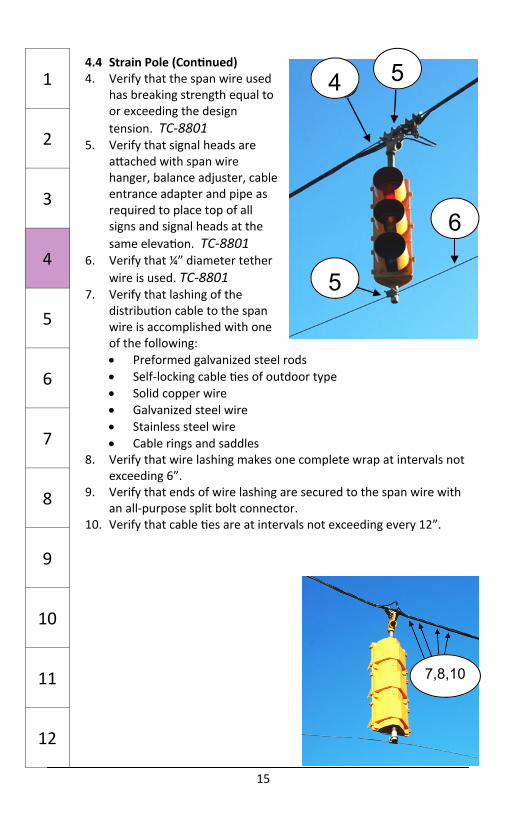
4.4 Strain Pole (Con nued) 4. Verify that the span wire used
has breaking strength equal to or exceeding the design tension. TC‐8801
5. Verify that signal heads are a ached with span wire hanger, balance adjuster, cable entrance adapter and pipe as required to place top of all signs and signal heads at the same eleva on. TC‐8801
6. Verify that ¼” diameter tether wire is used. TC‐8801
7. Verify that lashing of the distribu on cable to the span wire is accomplished with one of the following: Preformed galvanized steel rods Self‐locking cable es of outdoor type Solid copper wire Galvanized steel wire Stainless steel wire Cable rings and saddles
8. Verify that wire lashing makes one complete wrap at intervals not exceeding 6”.
9. Verify that ends of wire lashing are secured to the span wire with an all‐purpose split bolt connector.
10. Verify that cable es are at intervals not exceeding every 12”.
1
2
3
4
5
6
7
8
9
10
11
12
6
5
5 4
7,8,10
16
4.4 Strain Pole (Con nued)
11. Verify that the cable entrance is a minimum of 4” in diameter. TC‐8801
12. Verify with a visual inspec on from the groundthat an insulated grommet is used for weather proofing the wire inlet. PUB 408 Sec on 1104.02(a)6
13. Verify with a visual inspec on from the ground the span wire and an individual clamp is used for each span wire or tether wire. TC‐8801
4.5 Pedestal Poles 4.5.1 Pedestal Poles (Base Plate Type)
1. Verify that the pole is tall enough to provide 8’ minimum, 10’ maximum height above grade to bo om of signal housing. TC‐8803
2. Verify that hand hole opening is 3” x 5” with a minimum frame thickness of 3/8” and that the centerline is 18” above the base plate. TC‐8803 and TC‐8801
3. Verify that the base plate is con nuously welded to the pole. TC‐8803
4. Verify that non‐shrink mortar is used beneath the base plate in paved areas and metal screening is placed beneath the base plate of the pole in unpaved areas. Pub. 408 sec. 951.3(c))
5. A er erec on of pole and moun ng of signal hardware, verify that the minimum clearance as indicated in Pub 149 is obtained from curb to the nearest element of the pole or signal head. TC‐8801, TC‐8803
1
2
3
4
5
6
7
8
9
10
11
12
12 13
11

15
4.4 Strain Pole (Con nued) 4. Verify that the span wire used
has breaking strength equal to or exceeding the design tension. TC‐8801
5. Verify that signal heads are a ached with span wire hanger, balance adjuster, cable entrance adapter and pipe as required to place top of all signs and signal heads at the same eleva on. TC‐8801
6. Verify that ¼” diameter tether wire is used. TC‐8801
7. Verify that lashing of the distribu on cable to the span wire is accomplished with one of the following: Preformed galvanized steel rods Self‐locking cable es of outdoor type Solid copper wire Galvanized steel wire Stainless steel wire Cable rings and saddles
8. Verify that wire lashing makes one complete wrap at intervals not exceeding 6”.
9. Verify that ends of wire lashing are secured to the span wire with an all‐purpose split bolt connector.
10. Verify that cable es are at intervals not exceeding every 12”.
1
2
3
4
5
6
7
8
9
10
11
12
6
5
5 4
7,8,10
16
4.4 Strain Pole (Con nued)
11. Verify that the cable entrance is a minimum of 4” in diameter. TC‐8801
12. Verify with a visual inspec on from the groundthat an insulated grommet is used for weather proofing the wire inlet. PUB 408 Sec on 1104.02(a)6
13. Verify with a visual inspec on from the ground the span wire and an individual clamp is used for each span wire or tether wire. TC‐8801
4.5 Pedestal Poles 4.5.1 Pedestal Poles (Base Plate Type)
1. Verify that the pole is tall enough to provide 8’ minimum, 10’ maximum height above grade to bo om of signal housing. TC‐8803
2. Verify that hand hole opening is 3” x 5” with a minimum frame thickness of 3/8” and that the centerline is 18” above the base plate. TC‐8803 and TC‐8801
3. Verify that the base plate is con nuously welded to the pole. TC‐8803
4. Verify that non‐shrink mortar is used beneath the base plate in paved areas and metal screening is placed beneath the base plate of the pole in unpaved areas. Pub. 408 sec. 951.3(c))
5. A er erec on of pole and moun ng of signal hardware, verify that the minimum clearance as indicated in Pub 149 is obtained from curb to the nearest element of the pole or signal head. TC‐8801, TC‐8803
1
2
3
4
5
6
7
8
9
10
11
12
12 13
11
17
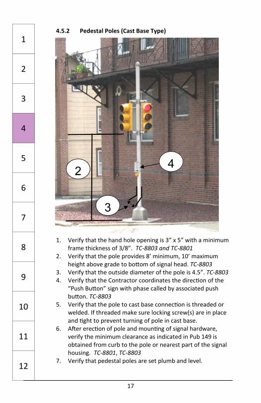
4.5.2 Pedestal Poles (Cast Base Type)
1. Verify that the hand hole opening is 3” x 5” with a minimum frame thickness of 3/8”. TC‐8803 and TC‐8801
2. Verify that the pole provides 8’ minimum, 10’ maximum height above grade to bo om of signal head. TC‐8803
3. Verify that the outside diameter of the pole is 4.5”. TC‐8803 4. Verify that the Contractor coordinates the direc on of the
“Push Bu on” sign with phase called by associated push bu on. TC‐8803
5. Verify that the pole to cast base connec on is threaded or welded. If threaded make sure locking screw(s) are in place and ght to prevent turning of pole in cast base.
6. A er erec on of pole and moun ng of signal hardware, verify the minimum clearance as indicated in Pub 149 is obtained from curb to the pole or nearest part of the signal housing. TC‐8801, TC‐8803
7. Verify that pedestal poles are set plumb and level.
1
2
3
4
5
6
7
8
9
10
11
12
3
4 2
18
4.6 Pedestrian Pushbu on Poles 1. Verify that poles are placed correctly in rela on to the
loca on of the curb ramps. TC‐8803 2. Verify that the pole founda ons are correct for the type of
pushbu on pole being installed TC‐8803 3. Verify that the poles are 3” Galvanized Rigid Steel Conduit,
except Type C and Type F poles which should be 4.5” O.D. Schedule 40 TC‐8803
4. Verify that the top of the pole is 60” (5 feet) above finished grade and that a galvanized steel or aluminum cap is in place TC‐8803
5. Verify that all accessibility features are compliant with PennDOT Publica on 13M (DM‐2), Chapter 6, Publica on 72M (RC Standards) criteria and Publica on 149 TC‐8803
6. Verify that the top of the founda on is flush with the surface of adjacent pavement when installed in pavement and that there is a 1/2 " pre‐molded expansion joint filler between founda on and adjacent pavement TC‐8803
7. Verify that if a pedestrian pushbu on extension arm is used, it is 3” or less. If it measures between 3" to 12", obtain district approval prior to installa on. Do not allow installa on of arms longer than 12”. TC‐8803
1
2
3
4
5
6
7
8
9
10
11
12
4.7 Wood Poles 1. Verify that temporary wood poles are in accordance with PUB
408 Sec on 1104.02(f). 2. Verify that the Contractor installs service poles in accordance
with PUB 408 Sec on 910.3(k).
17
4.5.2 Pedestal Poles (Cast Base Type)
1. Verify that the hand hole opening is 3” x 5” with a minimum frame thickness of 3/8”. TC‐8803 and TC‐8801
2. Verify that the pole provides 8’ minimum, 10’ maximum height above grade to bo om of signal head. TC‐8803
3. Verify that the outside diameter of the pole is 4.5”. TC‐8803 4. Verify that the Contractor coordinates the direc on of the
“Push Bu on” sign with phase called by associated push bu on. TC‐8803
5. Verify that the pole to cast base connec on is threaded or welded. If threaded make sure locking screw(s) are in place and ght to prevent turning of pole in cast base.
6. A er erec on of pole and moun ng of signal hardware, verify the minimum clearance as indicated in Pub 149 is obtained from curb to the pole or nearest part of the signal housing. TC‐8801, TC‐8803
7. Verify that pedestal poles are set plumb and level.
1
2
3
4
5
6
7
8
9
10
11
12
3
4 2
18
4.6 Pedestrian Pushbu on Poles 1. Verify that poles are placed correctly in rela on to the
loca on of the curb ramps. TC‐8803 2. Verify that the pole founda ons are correct for the type of
pushbu on pole being installed TC‐8803 3. Verify that the poles are 3” Galvanized Rigid Steel Conduit,
except Type C and Type F poles which should be 4.5” O.D. Schedule 40 TC‐8803
4. Verify that the top of the pole is 60” (5 feet) above finished grade and that a galvanized steel or aluminum cap is in place TC‐8803
5. Verify that all accessibility features are compliant with PennDOT Publica on 13M (DM‐2), Chapter 6, Publica on 72M (RC Standards) criteria and Publica on 149 TC‐8803
6. Verify that the top of the founda on is flush with the surface of adjacent pavement when installed in pavement and that there is a 1/2 " pre‐molded expansion joint filler between founda on and adjacent pavement TC‐8803
7. Verify that if a pedestrian pushbu on extension arm is used, it is 3” or less. If it measures between 3" to 12", obtain district approval prior to installa on. Do not allow installa on of arms longer than 12”. TC‐8803
1
2
3
4
5
6
7
8
9
10
11
12
4.7 Wood Poles 1. Verify that temporary wood poles are in accordance with PUB
408 Sec on 1104.02(f). 2. Verify that the Contractor installs service poles in accordance
with PUB 408 Sec on 910.3(k).
19
5.0 Traffic Signal Subsurface Facili es (PUB 408 Sec ons 954 and 1104.05)
5.1 Trench and Backfill 5.1.1 Trench and Backfill Type I (in earth) TC‐8804 Sheet 2 and PUB 408 Sec on 954.3 1. Verify that the trench is wide enough to allow proper
installa on, backfill and compac on of the trench and that at least 1” can be maintained between each conduit and between the conduit and the edge of the trench.
2. Verify that the trench is deep enough to provide at least 24” of cover to the top of the conduit. TC‐8806
3. Verify that plas c marking tape is placed in the last layer of back‐fill material for the en re length of the trench. Pub 408 Sec on 910.3.(c)
5.1.2 Trench and Backfill Type II (in sidewalk or paved
shoulder) TC‐8804 Sheet 2 and PUB 408 Sec on 954.3 1. Verify that special provisions do not call for special ac ons
including full sidewalk slab replacement. 2. Verify that the sidewalk or paved surface is saw‐cut at the
nearest construc on joint. 3. Verify that the trench is wide enough to allow proper
installa on, backfill and compac on of the trench and that at least 1” can be maintained between each conduit and between the conduit and the edge of the trench.
4. Verify that the trench is deep enough to provide at least 24” of cover from the top of the conduit to the bo om of the sub‐base.
5. Verify that plas c marking tape is placed in the last layer of back‐fill material for the en re length of the trench. Pub 408 Sec on 910.3.(c)
6. Verify that the sub‐base is replaced in kind. 7. Verify that the pavement surface is replaced in kind.
1
2
3
4
5
6
7
8
9
10
11
12
20
5.1.3 Trench and Backfill Type III (Roadway) TC‐8804 Sheet 2 and PUB 408 Sec on 954.3
1. Verify that the trench is wide enough to allow proper installa on, backfill and compac on of the trench and that at least 1” can be maintained between each conduit and between the conduit and the edge of the trench.
2. Verify that the surface on each side of the trench is saw‐cut to a minimum depth of 3”.
3. Verify that the trench is deep enough to provide at least 24” of cover from the top of the conduit to the bo om of the sub‐base.
4. Verify that bedding soil for the conduits has been placed at the bo om of the trench. PUB 408 Sec on 206.2(a)
5. Verify that the contractor backfills the trench as soon as possible.
6. Verify that plas c marking tape is placed in the last layer of back‐fill material for the en re length of the trench. Pub 408 Sec on 910.3.(c)
7. Verify that the sub‐base is replaced as specified within the construc on plans or as specified in PUB 408 Sec on 954.
8. Verify that the trench is backfilled with Class A cement concrete up to the bo om of the exis ng sub‐base.
9. Verify that the pavement is restored as specified in PUB 408 Sec on 954.
5.1.4 Trench and Backfill Type IV (Roadway) TC‐8804 Sheet 2 and PUB 408 Sec on 954.3
1. Verify that the trench is wide enough to allow proper installa on, backfill and compac on of the trench and that at least 1” can be maintained between each conduit and between the conduit and the edge of the trench.
2. Verify that the surface on each side of the trench is saw‐cut to a minimum depth of 3”.
3. Verify that the trench is deep enough to provide at least 24” of cover from the top of the conduit to the bo om of the sub‐base.
4. Verify that bedding soil for the conduits has been placed at the bo om of the trench. Pub 408 Sec on 206.2(a)
5. Verify that plas c marking tape was placed within the last layer of backfill for the en re length of the trench. Pub 408 Sec on 910.3.
6. Verify that the sub‐base and pavement are both replaced as specified within the construc on plans or as specified in Pub 408 Sec on 954.
1
2
3
4
5
6
7
8
9
10
11
12

21
5.1.5 Trench and Backfill Direc onal Boring PUB 408 Sec on 954.3(b)
1. Verify that the Contractor has the appropriate erosion and sedimenta on control measures in place prior to boring.
2. Verify that boring pits are a minimum of 2’ from the edge of roadway.
3. Verify that boring is below the exis ng roadway subbase layer.
4. Verify that boring pits are covered with adequate protec on if the drilling opera on is le overnight.
5. Do not allow the use of pneuma c hammers.
5.2 Conduit PUB 408 Sec on 1101.09(a) & (b) 5.2.1 PVC (Polyvinyl Chloride) 1. Verify that all PVC conduit, conduit fi ngs, and conduit
elbows are all supplied from the same manufacturer. 2. Verify that the cement is labeled by or recommended by the
conduit manufacturer. 3. Verify that expansion/
deflec on fi ngs are provided for conduit mounted on or within structures. Standard Drawing BC 721M (BC‐721)
4. Verify that conduit ends within junc on boxes or founda ons are restricted with a rodent‐proof filler. PUB 408 Sec on 954.3(c)
5. Verify that the conduit maintains at least 12” separa on from other underground u li es PUB 408 Sec on 954.3(c)
6. Verify that high impact spacers are in place every 8’ on center if more than two rigid non‐metallic conduits are installed in a common trench. PUB 408 Sec on 954.3(c)
7. Verify that underground conduits are at least 2” diameter unless otherwise specified. PUB 408 Sec on 910.3(g) & TC‐8804 Sheet 1
8. Verify that each conduit shall have a bell end or bushing to protect cables leaving the conduit.
1
2
3
4
5
6
7
8
9
10
11
12
22
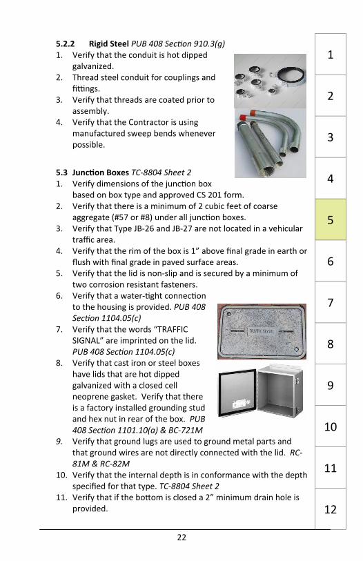
5.2.2 Rigid Steel PUB 408 Sec on 910.3(g) 1. Verify that the conduit is hot dipped
galvanized. 2. Thread steel conduit for couplings and
fi ngs. 3. Verify that threads are coated prior to
assembly. 4. Verify that the Contractor is using
manufactured sweep bends whenever possible.
5.3 Junc on Boxes TC‐8804 Sheet 2 1. Verify dimensions of the junc on box
based on box type and approved CS 201 form. 2. Verify that there is a minimum of 2 cubic feet of coarse
aggregate (#57 or #8) under all junc on boxes. 3. Verify that Type JB‐26 and JB‐27 are not located in a vehicular
traffic area. 4. Verify that the rim of the box is 1” above final grade in earth or
flush with final grade in paved surface areas. 5. Verify that the lid is non‐slip and is secured by a minimum of
two corrosion resistant fasteners. 6. Verify that a water‐ ght connec on
to the housing is provided. PUB 408 Sec on 1104.05(c)
7. Verify that the words “TRAFFIC SIGNAL” are imprinted on the lid. PUB 408 Sec on 1104.05(c)
8. Verify that cast iron or steel boxes have lids that are hot dipped galvanized with a closed cell neoprene gasket. Verify that there is a factory installed grounding stud and hex nut in rear of the box. PUB 408 Sec on 1101.10(a) & BC‐721M
9. Verify that ground lugs are used to ground metal parts and that ground wires are not directly connected with the lid. RC‐81M & RC‐82M
10. Verify that the internal depth is in conformance with the depth specified for that type. TC‐8804 Sheet 2
11. Verify that if the bo om is closed a 2” minimum drain hole is provided.
1
2
3
4
5
6
7
8
9
10
11
12
21
5.1.5 Trench and Backfill Direc onal Boring PUB 408 Sec on 954.3(b)
1. Verify that the Contractor has the appropriate erosion and sedimenta on control measures in place prior to boring.
2. Verify that boring pits are a minimum of 2’ from the edge of roadway.
3. Verify that boring is below the exis ng roadway subbase layer.
4. Verify that boring pits are covered with adequate protec on if the drilling opera on is le overnight.
5. Do not allow the use of pneuma c hammers.
5.2 Conduit PUB 408 Sec on 1101.09(a) & (b) 5.2.1 PVC (Polyvinyl Chloride) 1. Verify that all PVC conduit, conduit fi ngs, and conduit
elbows are all supplied from the same manufacturer. 2. Verify that the cement is labeled by or recommended by the
conduit manufacturer. 3. Verify that expansion/
deflec on fi ngs are provided for conduit mounted on or within structures. Standard Drawing BC 721M (BC‐721)
4. Verify that conduit ends within junc on boxes or founda ons are restricted with a rodent‐proof filler. PUB 408 Sec on 954.3(c)
5. Verify that the conduit maintains at least 12” separa on from other underground u li es PUB 408 Sec on 954.3(c)
6. Verify that high impact spacers are in place every 8’ on center if more than two rigid non‐metallic conduits are installed in a common trench. PUB 408 Sec on 954.3(c)
7. Verify that underground conduits are at least 2” diameter unless otherwise specified. PUB 408 Sec on 910.3(g) & TC‐8804 Sheet 1
8. Verify that each conduit shall have a bell end or bushing to protect cables leaving the conduit.
1
2
3
4
5
6
7
8
9
10
11
12
22
5.2.2 Rigid Steel PUB 408 Sec on 910.3(g) 1. Verify that the conduit is hot dipped
galvanized. 2. Thread steel conduit for couplings and
fi ngs. 3. Verify that threads are coated prior to
assembly. 4. Verify that the Contractor is using
manufactured sweep bends whenever possible.
5.3 Junc on Boxes TC‐8804 Sheet 2 1. Verify dimensions of the junc on box
based on box type and approved CS 201 form. 2. Verify that there is a minimum of 2 cubic feet of coarse
aggregate (#57 or #8) under all junc on boxes. 3. Verify that Type JB‐26 and JB‐27 are not located in a vehicular
traffic area. 4. Verify that the rim of the box is 1” above final grade in earth or
flush with final grade in paved surface areas. 5. Verify that the lid is non‐slip and is secured by a minimum of
two corrosion resistant fasteners. 6. Verify that a water‐ ght connec on
to the housing is provided. PUB 408 Sec on 1104.05(c)
7. Verify that the words “TRAFFIC SIGNAL” are imprinted on the lid. PUB 408 Sec on 1104.05(c)
8. Verify that cast iron or steel boxes have lids that are hot dipped galvanized with a closed cell neoprene gasket. Verify that there is a factory installed grounding stud and hex nut in rear of the box. PUB 408 Sec on 1101.10(a) & BC‐721M
9. Verify that ground lugs are used to ground metal parts and that ground wires are not directly connected with the lid. RC‐81M & RC‐82M
10. Verify that the internal depth is in conformance with the depth specified for that type. TC‐8804 Sheet 2
11. Verify that if the bo om is closed a 2” minimum drain hole is provided.
1
2
3
4
5
6
7
8
9
10
11
12

23
6.0 Controllers (PUB 408Sec ons 952 and 1104.03)
6.1 Approval Lis ngs 1. Verify that the controller assembly is on the approved CS‐201
form. 2. Obtain documenta on from the contractor verifying the
controller assembly was shop tested. 6.2 Controller Founda ons (TC‐8802) 6.2.1 In Earth 1. Verify that the plans call for a base mounted (Type I moun ng)
controller assembly. 2. Verify that the intersec on and controller can be observed
simultaneously from the proposed loca on prior to pouring the founda on.
3. Verify that the founda on is 4” larger than the cabinet on all sides.
4. Verify that the depth of the founda on is 31” plus the diameter of the largest conduit that runs through the founda on.
5. Verify that the concrete pad in front of the controller extends 28” from the cabinet face with a depth tapering from 12” at the cabinet founda on to 6” at the front edge of the concrete pad.
6. Verify that there is a ¾” chamfer on all sides of the control cabinet founda on.
7. Verify that the top of the control cabinet founda on is elevated 4” above the finish grade at its lowest point.
8. Verify that there will be no conflicts between conduits and the cabinet before construc ng the founda on.
9. Verify that a 1” diameter screened drain pipe is installed from the bo om rear of the cabinet to the edge of the founda on, discharging above grade.
10. Verify that the cabinet anchor bolts cast into the founda on are ½” x 12”.
11. If anchor bolts are not used, verify that ½” x 3 ¾ ” expansion bolts are used.
12. Verify that caulking compound was applied around the en re cabinet enclosure between the base of the cabinet and the concrete founda on. Verify that caulking is in accordance with PUB 408 Sec on 705.8.
1
2
3
4
5
6
7
8
9
10
11
12
24
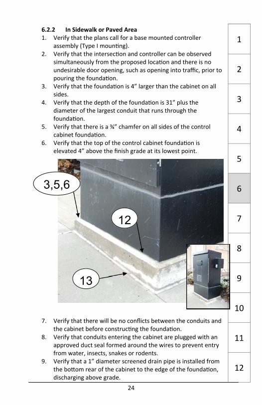
6.2.2 In Sidewalk or Paved Area 1. Verify that the plans call for a base mounted controller
assembly (Type I moun ng). 2. Verify that the intersec on and controller can be observed
simultaneously from the proposed loca on and there is no undesirable door opening, such as opening into traffic, prior to pouring the founda on.
3. Verify that the founda on is 4” larger than the cabinet on all sides.
4. Verify that the depth of the founda on is 31” plus the diameter of the largest conduit that runs through the founda on.
5. Verify that there is a ¾” chamfer on all sides of the control cabinet founda on.
6. Verify that the top of the control cabinet founda on is elevated 4” above the finish grade at its lowest point.
7. Verify that there will be no conflicts between the conduits and the cabinet before construc ng the founda on.
8. Verify that conduits entering the cabinet are plugged with an approved duct seal formed around the wires to prevent entry from water, insects, snakes or rodents.
9. Verify that a 1” diameter screened drain pipe is installed from the bo om rear of the cabinet to the edge of the founda on, discharging above grade.
1
2
3
4
5
6
7
8
9
10
11
12
13
12
3,5,6
23
6.0 Controllers (PUB 408Sec ons 952 and 1104.03)
6.1 Approval Lis ngs 1. Verify that the controller assembly is on the approved CS‐201
form. 2. Obtain documenta on from the contractor verifying the
controller assembly was shop tested. 6.2 Controller Founda ons (TC‐8802) 6.2.1 In Earth 1. Verify that the plans call for a base mounted (Type I moun ng)
controller assembly. 2. Verify that the intersec on and controller can be observed
simultaneously from the proposed loca on prior to pouring the founda on.
3. Verify that the founda on is 4” larger than the cabinet on all sides.
4. Verify that the depth of the founda on is 31” plus the diameter of the largest conduit that runs through the founda on.
5. Verify that the concrete pad in front of the controller extends 28” from the cabinet face with a depth tapering from 12” at the cabinet founda on to 6” at the front edge of the concrete pad.
6. Verify that there is a ¾” chamfer on all sides of the control cabinet founda on.
7. Verify that the top of the control cabinet founda on is elevated 4” above the finish grade at its lowest point.
8. Verify that there will be no conflicts between conduits and the cabinet before construc ng the founda on.
9. Verify that a 1” diameter screened drain pipe is installed from the bo om rear of the cabinet to the edge of the founda on, discharging above grade.
10. Verify that the cabinet anchor bolts cast into the founda on are ½” x 12”.
11. If anchor bolts are not used, verify that ½” x 3 ¾ ” expansion bolts are used.
12. Verify that caulking compound was applied around the en re cabinet enclosure between the base of the cabinet and the concrete founda on. Verify that caulking is in accordance with PUB 408 Sec on 705.8.
1
2
3
4
5
6
7
8
9
10
11
12
24
6.2.2 In Sidewalk or Paved Area 1. Verify that the plans call for a base mounted controller
assembly (Type I moun ng). 2. Verify that the intersec on and controller can be observed
simultaneously from the proposed loca on and there is no undesirable door opening, such as opening into traffic, prior to pouring the founda on.
3. Verify that the founda on is 4” larger than the cabinet on all sides.
4. Verify that the depth of the founda on is 31” plus the diameter of the largest conduit that runs through the founda on.
5. Verify that there is a ¾” chamfer on all sides of the control cabinet founda on.
6. Verify that the top of the control cabinet founda on is elevated 4” above the finish grade at its lowest point.
7. Verify that there will be no conflicts between the conduits and the cabinet before construc ng the founda on.
8. Verify that conduits entering the cabinet are plugged with an approved duct seal formed around the wires to prevent entry from water, insects, snakes or rodents.
9. Verify that a 1” diameter screened drain pipe is installed from the bo om rear of the cabinet to the edge of the founda on, discharging above grade.
1
2
3
4
5
6
7
8
9
10
11
12
13
12
3,5,6

25
6.2.2 In Sidewalk or Paved Area (Con nued) 10. Verify that the cabinet anchor bolts cast into the founda on
are ½” x 12”. 11. If anchor bolts are not used, verify that ½” x 3¾” expansion
bolts are used. 12. Verify that caulking compound was applied around the en re
cabinet enclosure between the base of the cabinet and the concrete founda on. Verify that caulking is in accordance with PUB 408 Sec on 705.8.
13. Verify that ½” pre‐molded expansion joint filler was installed between the founda on and the surrounding paved area.
6.3 Controller Cabinets 6.3.1 Type I Moun ng (Ground Mounted) 1. Verify that the plans call for a base mounted controller
assembly (Type I moun ng). 2. Verify that the controller cabinet is equipped with the
following items: a. Full height con nuously welded piano hinge. Type 170 ‐
PUB 408 Sec on 1104.03(b).2.f NEMA – PUB 408 Sec on 1104.03(b)1.f.1
b. Key operated spring lock. Type 170 ‐ PUB 408 Sec on 1104.03(b)2.f
c. Cover vents with full perimeter frame disposable filter securely held in place. NEMA – PUB 408 Sec on 1104.03(b)1.f.2
d. Three point draw roller type door latching mechanism required. Type 170 ‐ : PUB408 Sec on 1104.03(b)2.f NEMA – : PUB 408 Sec on 1104.03(b)1.f.1
e. 15” minimum clearance between bo om of cabinet and the terminals, equipment, or devices. TC‐8802
3. Verify that conduits entering the cabinet are plugged with an approved duct seal formed around the wires to prevent entry from water, insects, snakes or rodents.
1
2
3
4
5
6
7
8
9
10
11
12
2d
2b
2c 2d
2a
26
6.3.2 Type II Moun ng (Pole Mounted) 1. Verify that the plans call for a pole mounted controller
assembly (Type II moun ng). 2. Verify that there is no undesirable door opening, such as
opening into traffic 3. Verify that the bo om of the cabinet is not higher than 27”
when the cabinet extends over a sidewalk or walkway. 4. Verify that the centerline of the cabinet is between 4’‐3” and
4’‐6” above final grade. 5. Verify that no por on of any equipment (except fan and light)
is higher in the cabinet than the top of the door. TC‐8802 6. Verify that the door latching mechanism is a three point draw
roller type. PUB 408 Sec on 1104.03(b) 7. Verify that vents are covered with a full perimeter, framed,
disposable, filter securely held in place. NEMA‐: PUB 408 Sec on 1104.03(b).1.f.2
8. Verify that all terminals, equipment and devices are at least 3” above the bo om of cabinet. TC‐8802
6.4 Manual Test Control 1. Review the requirements in PUB 408 for the type of controller
Type 170 ‐ Sec ons 1104.03 (b)2.b & 1104.03(b)2.f) NEMA ‐ Sec on 1104.03(b)1.b) Type 2070 ‐ Sec on 1104.03(b)3.b)
2. Verify that the manual control panel includes a method to switch the signal from automa c to manual control.
3. Verify that the manual control panel is in a water ght enclosure compartment accessed separately from the main control cabinet and locked with a standard police key.
4. Verify that the plug in hand control cable is neatly tucked in the enclosure.
1
2
3
4
5
6
7
8
9
10
11
12 2 4
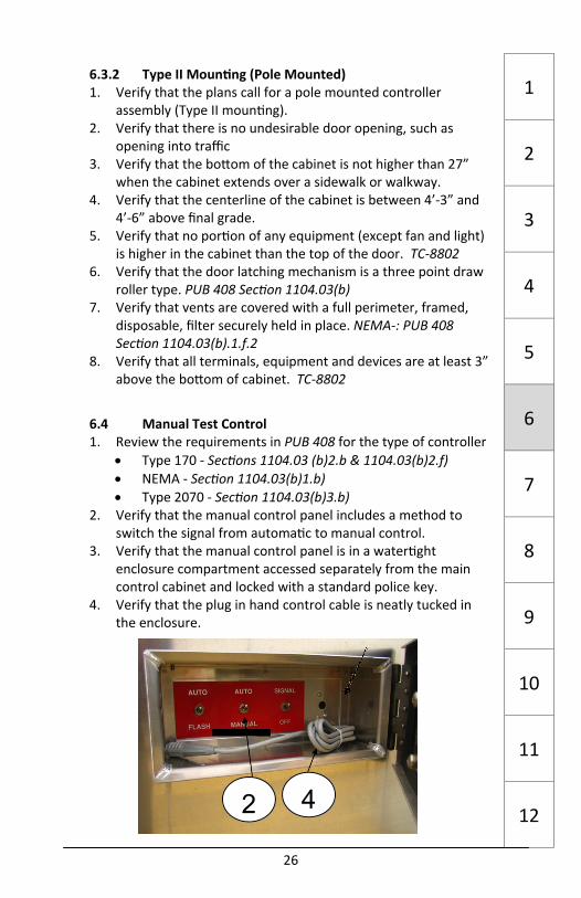
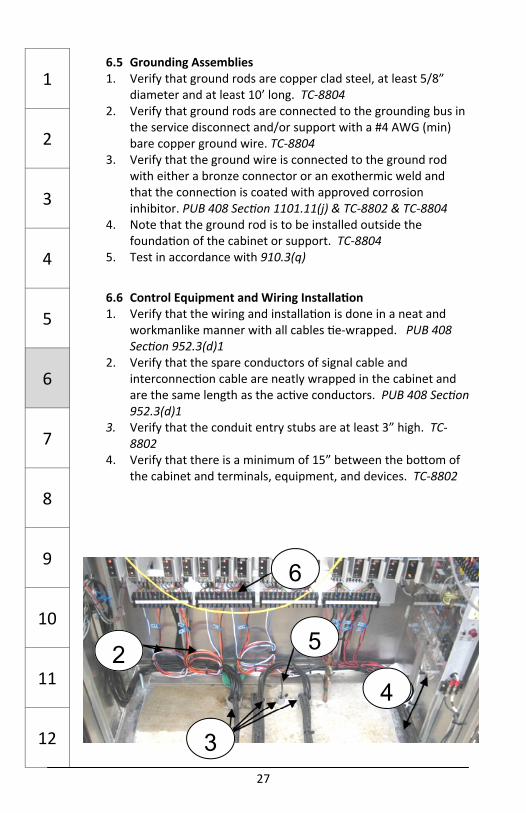
27
6.5 Grounding Assemblies 1. Verify that ground rods are copper clad steel, at least 5/8”
diameter and at least 10’ long. TC‐8804 2. Verify that ground rods are connected to the grounding bus in
the service disconnect and/or support with a #4 AWG (min) bare copper ground wire. TC‐8804
3. Verify that the ground wire is connected to the ground rod with either a bronze connector or an exothermic weld and that the connec on is coated with approved corrosion inhibitor. PUB 408 Sec on 1101.11(j) & TC‐8802 & TC‐8804
4. Note that the ground rod is to be installed outside the founda on of the cabinet or support. TC‐8804
5. Test in accordance with 910.3(q)
6.6 Control Equipment and Wiring Installa on 1. Verify that the wiring and installa on is done in a neat and
workmanlike manner with all cables e‐wrapped. PUB 408 Sec on 952.3(d)1
2. Verify that the spare conductors of signal cable and interconnec on cable are neatly wrapped in the cabinet and are the same length as the ac ve conductors. PUB 408 Sec on 952.3(d)1
3. Verify that the conduit entry stubs are at least 3” high. TC‐8802
4. Verify that there is a minimum of 15” between the bo om of the cabinet and terminals, equipment, and devices. TC‐8802
1
2
3
4
5
6
7
8
9
10
11
12
4 2
6
3
5
28
6.6 Control Equipment and Wiring Installa on (Con nued) 5. Verify that a #8 AWG equipment grounding conductor is
connected to the service disconnect. TC‐8804 6. Verify that there is only one conductor per screw on the
terminal block or use pressure‐type mechanical lugs for mul ple conductors. PUB 408 Sect. 954.3(e)1
7. Verify that the wiring and cables are neatly arranged and e‐wrapped. PUB 408 Sec on 952.3(d)1
8. Verify that RFI Line Filter conforms to PUB 408 Sec on 1104.03(c)3.b
9. Verify that the chassis ground bar is connected to the grounding system.
10. Verify that the surge protec on conforms to PUB 408 Sec on 1104.03(c)3.c
1
2
3
4
5
6
7
8
9
10
11
12
8
10
9
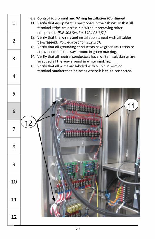
29
6.6 Control Equipment and Wiring Installa on (Con nued) 11. Verify that equipment is posi oned in the cabinet so that all
terminal strips are accessible without removing other equipment. PUB 408 Sec on 1104.03(b)2.f
12. Verify that the wiring and installa on is neat with all cables e‐wrapped. PUB 408 Sec on 952.3(d)1
13. Verify that all grounding conductors have green insula on or are wrapped all the way around in green marking.
14. Verify that all neutral conductors have white insula on or are wrapped all the way around in white marking.
15. Verify that all wires are labeled with a unique wire or terminal number that indicates where it is to be connected.
1
2
3
4
5
6
7
8
9
10
11
12
12
11
30
6.6 Control Equipment and Wiring Installa on (Con nued) 16. If specified, verify that access to the transfer switch and twist
lock receptacle for connec on to an emergency generator is installed behind a locked enclosure with police access. PUB 408 Sec on 1104.03(b)2.f
17. Verify that there is a transfer switch relay to disconnect the permanent power source and connect the emergency power source. PUB 408 Sec on 1104.03(b)2.f
18. Verify that there is a Ground Fault Circuit Interrupter (GFCI) protected convenience outlet on a dedicated 20 amp minimum circuit. PUB 408 Sec on 1104.5(j) and 1104.03(c)3.a
19. If specified, verify that there is a UPS/Ba ery back‐up capable of a minimum 4 hour back‐up opera on. PUB 408 Sec on 1104.05(i)
20. If specified, verify that a fiber op c patch panel is included. 21. If specified, verify that a fiber op c cable loop is included.
1
2
3
4
5
6
7
8
9
10
11
12
18
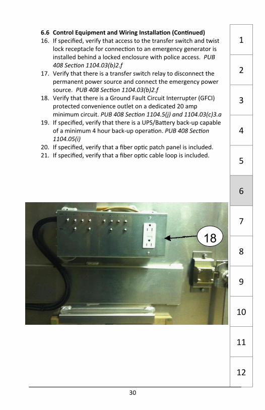
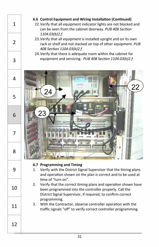
31
6.6 Control Equipment and Wiring Installa on (Con nued) 22. Verify that all equipment indicator lights are not blocked and
can be seen from the cabinet doorway. PUB 408 Sec on 1104.03(b)2.f
23. Verify that all equipment is installed upright and on its own rack or shelf and not stacked on top of other equipment. PUB 408 Sec on 1104.03(b)2.f
24. Verify that there is adequate room within the cabinet for equipment and servicing. PUB 408 Sec on 1104.03(b)2.f
6.7 Programming and Timing 1. Verify with the District Signal Supervisor that the ming plans
and opera on shown on the plan is correct and to be used at me of “turn on”.
2. Verify that the correct ming plans and opera on shown have been programmed into the controller properly. Call the District Signal Supervisor, if required, to confirm correct programming.
3. With the Contractor, observe controller opera on with the traffic signals “off” to verify correct controller programming.
1
2
3
4
5
6
7
8
9
10
11
12
23
24 22
32
7.0 Signal Indica ons (Sec ons 955 and 1104.06) 7.1 Vehicular 1. Verify that the signal housing and LED modules are the size
and color specified on the traffic signal plan. Highway yellow is the standard signal housing color unless otherwise noted. PUB 408 Sec on 1106(a)1
2. Verify that overhead signals are installed with the top of the signal head at the same eleva on prior to installing the tether wire. TC‐8801 Sheet 2
3. Verify that drip loops at wire entrances to signal heads are secured with acceptable outdoor type cable es. PUB 408 Sec on 954.3(e)1 & 1104.05(b)5
4. Verify that there is a grommet at the wire entrance to the moun ng bracket. TC‐8801 Sheet 1
5. If op cally programmed signal heads are specified, verify that the Contractor coordinates the field programming of the signal heads with the District Signal Supervisor for cut‐off and distance limi ng.
6. Verify that the specific loca ons of overhead vehicular signal heads are as shown in the loca on indicated on the traffic signal permit plan.
7. Verify that the vehicular signal heads are generally aimed at approaching traffic that is 150’ in front of the stop line.
1
2
3
4
5
6
7
8
9
10
11
12 4 3
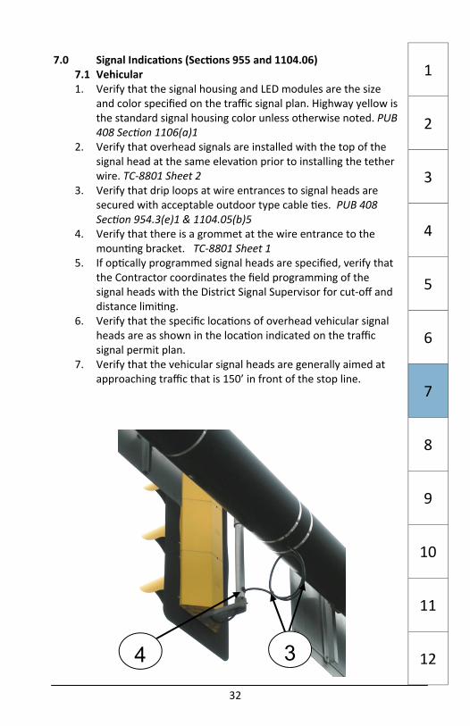
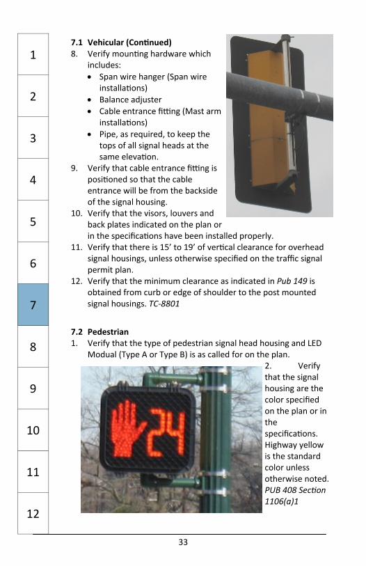
33
1
2
3
4
5
6
7
8
9
10
11
12
7.1 Vehicular (Con nued) 8. Verify moun ng hardware which
includes: Span wire hanger (Span wire
installa ons) Balance adjuster Cable entrance fi ng (Mast arm
installa ons) Pipe, as required, to keep the
tops of all signal heads at the same eleva on.
9. Verify that cable entrance fi ng is posi oned so that the cable entrance will be from the backside of the signal housing.
10. Verify that the visors, louvers and back plates indicated on the plan or in the specifica ons have been installed properly.
11. Verify that there is 15’ to 19’ of ver cal clearance for overhead signal housings, unless otherwise specified on the traffic signal permit plan.
12. Verify that the minimum clearance as indicated in Pub 149 is obtained from curb or edge of shoulder to the post mounted signal housings. TC‐8801
7.2 Pedestrian 1. Verify that the type of pedestrian signal head housing and LED
Modual (Type A or Type B) is as called for on the plan. 2. Verify that the signal housing are the color specified on the plan or in the specifica ons. Highway yellow is the standard color unless otherwise noted. PUB 408 Sec on 1106(a)1
34
1
2
3
4
5
6
7
8
9
10
11
12
7.2 Pedestrian (Con nued) 3. Verify that the signal housing are constructed of aluminum or
polycarbonate resin. The contractor has the op on to provide either unless otherwise specified. PUB 408 Sec on 1106(a)1
4. Verify that the minimum clearance as indicated in Pub 149 is obtained from curb or edge of shoulder to the post mounted signal housing. TC‐8801
5. Verify that the bo om of the signal head is between 7’ and 10’ above the sidewalk. If there is no sidewalk, verify that the bo om of the signal head is between 7’ and 10’ above the pavement grade at the centerline of the road. TC‐8801
7.3 Preemp on Fail Safe Indica ons 1. Verify that emergency vehicle preemp on is specified and
shown in the movement phase diagram. 2. Verify that the size and color of the confirma on light
supplied by the contractor is in accordance with the specifica ons. Coordinate with the District Signal Supervisor and the municipality.
3. At signals with emergency vehicle preemp on on intersec ng approaches, verify that confirma on lights are associated with the proper approach.
4. Verify that pre‐empt receivers are mounted in the right loca on and pointed in the correct direc on.

35
1
2
3
4
5
6
7
8
9
10
11
12
8.0 Electrical Distribu on (PUB 408 Sec ons 954 and 1104.05) 8.1 Grounding PUB 408 Sec on 954.3(d) and Sec on 1104.03(d) 1. Verify that a con nuous mechanical and electrical grounding
system exists connec ng the following items: Service disconnect enclosure Controller assembly and cabinet Traffic signal supports Ground rods Span wires Tether wires Steel conduit Metallic junc on boxes
2. Verify that Underwriter’s Laboratory listed bonding/grounding bushings are installed on the ends of all steel conduits and that the bushings are connected to the grounding system.
8.2 Signal Cable, Wiring and ID Tags 1. Verify that all signal cable, wiring and ancillary equipment are
included on the CS‐201 form. 2. Verify that lubricant is used to install cable in the conduit. If
new cable is installed in exis ng conduit verify that the conduit was cleaned in accordance with PUB 408 Sec on 910.3
3. Verify that signal wires and cables are spliced only in pole bases using waterproof resin‐filled wire nuts.
4. Verify that ground wires are spliced only in junc on boxes. 5. Verify that all cables at splices in pole bases or cabinets are
properly labeled or have ID tags a ached. 6. Verify that all terminal connec ons have been banded and the
appropriate coding used in accordance with PUB 408 Sec on 954.3.
7. Verify that all spare and unused conductors have been terminated on the ground buss.
8. Verify that enough signal cable slack is le for proper wiring connec ons and drip loops.
9. For span wire installa ons, verify that the cable is lashed to the span wire in accordance with TC‐8801.
10. Verify that drip loops have been included in all signal cables entering signal head housings. Verify that the cable enters the signal head housing at an upward angle to prevent water from entering the signal head. Verify that the drip loops are secured with outdoor‐type, self‐locking cable es. TC‐8801
36
1
2
3
4
5
6
7
8
9
10
11
12
8.3 Wiring Diagrams PUB 408 Sec on 1104.01(d) 1. Verify that the contractor provides three (3) copies of the cabinet
wiring diagram and manufacturer's ming plan for each controller assembly. If there are changes to the ming plan during tes ng, three new sets of ming plans are required.
8.4 Tes ng 1. Verify with the contractor that they cer fy that all equipment
and material has been checked and is in opera ng order prior to it being energized.
2. Verify and document the faulty or defec ve material that was removed and replaced to correct the condi on that halted the test.
3. Test grounding system in accordance with Pub 408 Sec on 910.3(q)
37
1
2
3
4
5
6
7
8
9
10
11
12
9.0 Detec on (Sec ons 956 and 1104.07) 9.1 Vehicular 9.1.1 Inductance Loops
Cu ng, Placing Wire and Sealing 1. Inspector In‐Charge will determine in which paving layer
(wearing course, base course or be “pre‐formed” under new concrete pavement) the plans or specifica ons call for the loop sensor to be installed.
2. Verify that sensors are located as indicated on the plan. Verify that the sawcu ng will not go through pavement joints or areas of deteriora ng pavement. Contact the District Signal Supervisor if there are any ques ons prior to installing loops.
3. Verify that the loop layout is in accordance with TC‐8806 and that the saw cut depth is constant for the en re loop sensor.
4. Verify that the slot is cleaned of moisture and debris, preferably with a compressed air hose.
5. Verify that the loop sensor wire is #14 AWG, IMSA Specifica on 51‐5. It is an insulated wire inside a PVC tube. PUB 408 Sec on 1104.07(b)1.a.
6. Verify that each saw cut slot has the required number of turns of sensor wire per detector as required to provide the specified inductance.
7. Verify that all wires in a common slot are proceeding in the same direc on.
8. Verify that the sensor wire is tamped into the slot with a non‐metallic tool.
9. Verify that the saw cut ends one foot (1') from the edge of pavement and a rotary drill is used to make a hole in the pavement. Verify that the sensor wire is installed through conduit to the junc on box by trenching through either the shoulder or sidewalk.
10. Verify that the splice of the sensor wire to the lead‐in wire is made only inside the junc on box. Verify that there is no other splicing of sensor wire. TC¬8806.
11. Verify that the ends of the conduit are properly sealed with duct seal a er the sensor wire is installed. TC‐8806.
12. Verify that the amplifiers are on the approved CS‐201 form. 13. Verify the values of the tests of the sensor a er installa on for
leakage resistance, series resistance, and inductance before sealing the saw cut slot. PUB 408 Sec on 956.03(a)1
38
1
2
3
4
5
6
7
8
9
10
11
12
Cu ng, Placing Wire and Sealing (Con nued) 14. Verify that the sealant used to seal the saw cut is in Bulle n 15
and that the manufacturer’s specifica ons for mixing and installa on are followed. Verify that the sealant is not placed when the temperature is under 32° F or during precipita on. PUB 408 Sec on 956.03(a)1
15. Verify that the slot is filled to within one eighth inch (1/8") of the pavement surface.
16. Verify that the excess sealant is removed, but not with the use of solvents. Do not allow traffic on the sealant un l it is properly cured.
17. Verify that loca on of the sensor wire is marked a er installa on to ensure that core samples do not sever the wire. Verify that all excess loop sensor wire or lead‐in wire is
banded in the junc on box to prevent movement which will result in false calls.
Verify a er tes ng inductance, a copy of the inductance readings is placed, along with the make and model number of the tes ng equipment, in the controller cabinet.
Lead‐in Cable and Splicing 1. Verify that detector lead‐in cable is #14 AWG, IMSA Specifica on
50‐2. PUB 408 Sec on 1104.07(a)2 2. Verify that the detector lead‐in cable is installed in one
con nuous length to the terminal strip in the controller cabinet. No splices are allowed in the lead‐in cable.
3. Verify that the detector lead‐in cable is spliced to the sensor wires as shown in TC‐8806 or by using another approved method.

39
1
2
3
4
5
6
7
8
9
10
11
12
9.1.1 Inductance Loops ( Con nued) Amplifiers
1. Verify that a er connec ng to the loop amplifier, the amplifier has been adjusted as per the manufacturer’s instruc ons to obtain the necessary sensi vity. Verify that no “false” calls are being placed by traffic moving in the opposite direc on.
2. Verify that the loop amplifiers are labeled with the correct phase and movement.
1,2
40
1
2
3
4
5
6
7
8
9
10
11
12
9.1.2 Video Detec on 1. Verify that the video detec on camera is mounted at the highest
point possible 2. Verify that each camera is provided with a sun shield. 3. Verify that all cables and connec ons are per the manufacturer’s
specifica ons. 4. Verify that each zone of video detec on on the plans is covered
by the system. 9.1.3 Microwave Radar, Digital Wave Radar, Magne c and
Magnetometer Detec on Systems
1. Verify which type of detec on system is specified. Coordinate with the District Traffic Signal Supervisor for the loca on and detec on zone coverage.
2. Verify that all installa on, cable and connec ons are per the manufacturer’s specifica ons.
1
2
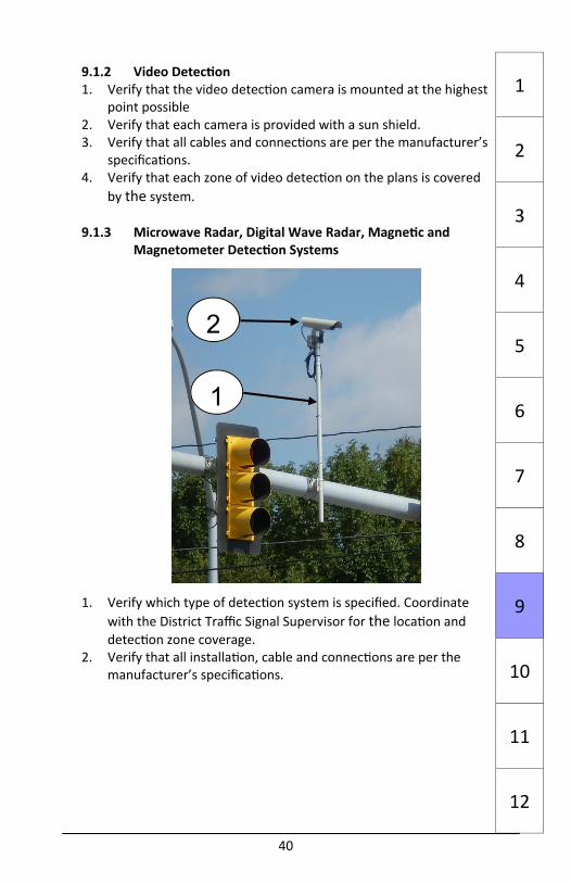
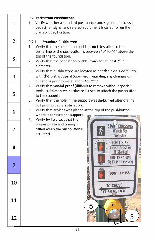
41
1
2
3
4
5
6
7
8
9
10
11
12
9.2 Pedestrian Pushbu ons 1. Verify whether a standard pushbu on and sign or an accessible
pedestrian signal and related equipment is called for on the plans or specifica ons.
9.2.1 Standard Pushbu on 1. Verify that the pedestrian pushbu on is installed so the
centerline of the pushbu on is between 40” to 44” above the top of the founda on.
2. Verify that the pedestrian pushbu ons are at least 2” in diameter.
3. Verify that pushbu ons are located as per the plan. Coordinate with the District Signal Supervisor regarding any changes or ques ons prior to installa on. TC‐8803
4. Verify that vandal‐proof (difficult to remove without special tools) stainless steel hardware is used to a ach the pushbu on to the support.
5. Verify that the hole in the support was de‐burred a er drilling but prior to cable installa on.
6. Verify that sealant was placed at the top of the pushbu on where it contacts the support.
7. Verify by field test that the proper phase and ming is called when the pushbu on is actuated.
5 3
42
1
2
3
4
5
6
7
8
9
10
11
12
9.2.2 Accessible Pedestrian Signal 1. Verify that the pedestrian pushbu ons are at least 2” in
diameter. 2. Verify that pushbu ons are located as per the plan. Coordinate
with the District Signal Supervisor regarding any changes or ques ons prior to installa on. TC‐8803
3. Verify that vandal‐proof (difficult to remove without special tools) stainless steel hardware was used to a ach the pushbu on to the support.
4. Verify that the hole in the support was de‐burred a er drilling but prior to cable installa on.
5. Verify that pushbu on, speaker and vibrotac le device are a ached to the support with the proper orienta on to the applicable crosswalk. Verify that speakers are not a ached to pedestrian indica ons.
6. Verify that sealant was placed at the top of the pushbu on, speaker and vibrotac le device where they contact the support.
7. Coordinate with the District Traffic Signal Supervisor to verify the types of audio messages to be used.
8. Verify by field test that the proper phase, audio messages and ming are called when actuated.
9. Verify the message displayed/opera ons of accessible pedestrian signals when emergency vehicle preemp on is invoked.
10. If volume of pedestrian signals does not self adjust to ambient noise, manual adjustments will be required.

43
1
2
3
4
5
6
7
8
9
10
11
12
9.3 Preemp on Systems 1. Verify which type of preemp on system is required by the plans
and specifica ons Audio, Op cal or Global Posi oning Satellite (GPS)
2. Verify the detector/receiver loca on prior to installa on. A minimum distance of 500’ away from the stop bar on the appropriate approach is recommended for a detec on of an actua ng vehicle.
3. Verify that any training requirements called for in the specifica ons are followed and that appropriate personnel are trained.
4. If there are issues with detec on, work with vendor to test emergency vehicle sirens/emi ers to confirm vehicles meet specifica ons.
5. If possible, it is desirable to test the preemp on system with the municipality’s actual responding units.
9.4 Other Preemp on Systems 1. Seek guidance from the Traffic Signal Supervisor when railroad
preemp on or other complex signal opera ons are indicated.
44
1
2
3
4
5
6
7
8
9
10
11
12
10.0 Pavement Markings and Signs 10.1 Pavement Marking Loca ons 1. Verify the loca on of crosswalks and stop lines with the District
Traffic Signal Supervisor prior to placement. 2. Verify coordina on of pavement marking and detec on zone
loca ons.
10.2 Placement of Pavement Marking Material 1. Verify that the type of pavement marking material called for in
the plan is applied in the field. 2. Coordinate the applica on of the pavement marking material
with the contractor to ensure the material is applied at the correct me in the project progress and that the weather and pavement condi ons are in accordance with the manufacturer’s specifica ons.

45
1
2
3
4
5
6
7
8
9
10
11
12
10.3 Sign Types and Loca ons 1. Verify the type of sign
installa on and loca on with the District Signal Supervisor prior to installa on. PUB 111M
2. Verify that the signs provided are from an approved sign manufacturer and that the supplier’s PennDOT iden fica on number is on the back of each sign.
3. Verify that the date of installa on is placed on the back of the sign with a permanent marker.
4. Verify that the faces of new signs are covered un l project condi ons are appropriate for their display.
46
1
2
3
4
5
6
7
8
9
10
11
12
11.0 Traffic Signal Systems (PUB 408 Sec ons 953 and 1104.04) 11.1 Equipment 1. Verify that the loca on of the master controller, master
coordina ng unit, or server matches the plans. 2. Verify that the required arrangements have been made with the
municipality and the u lity that will provide the communica ons connec on.
11.2 So ware 1. Verify the installa on of the proper number of traffic signal
system so ware packages, typically two; one package on a designated municipal computer and the other package on a designated Department computer. PUB 408 Sec on 953.3(d)1
2. Verify that all project specific intersec on graphics, intersec on data, overall system mapping, ming plans and other so ware programming has been completed. PUB 408 Sec on 953.3(d)2
11.3 Training 1. Verify that the proper amount of training on the traffic signal
system so ware has been completed. Amount of me varies by project. Coordinate with the District Signal Supervisor. PUB 408 Sec on 953.3(d)3
11.4 Communica ons 11.4.1 Radio PUB 408 Sec on 953.3(e) 1. Verify the appropriate radio units are installed at the master
controller and the local controllers and that each radio unit has repeater capability.
2. Verify that the correct type of antenna is installed at each intersec on as per the plan and that the antenna is pointed in the correct direc on.
2

47
1
2
3
4
5
6
7
8
9
10
11
12
11.4.1 Radio (Con nued) 3. Verify that all coaxial cable and antennas are grounded
properly and that lightning surge suppressors are installed correctly.
4. Verify that the Contractor monitors the radio communica on system tests to evaluate and adjust the radio system before use.
5. Verify that the Contractor provides all warran es and product informa on from the contractor for all installed equipment.
11.4.2 Cable PUB 408 Sec on 953.3(g) 1. Verify that all equipment, control cable and communica on
cable have been installed per the manufacturer’s requirements.
2. Verify that all cables are terminated on an approved terminal strip and do not have any splices.
3. Verify that the lightning and surge suppression equipment has been installed as specified.
4. Verify that the Contractor provides all warran es and product informa on from the contractor for all installed equipment.
11.4.3 Cellular PUB 408 Sec on 953.3(h) 1. Verify that the cellular modem has been installed at the master
controller and the local controllers. 2. Verify that the correct type of antenna is installed at each
intersec on and the size matches the modem to be used. 3. Verify that surge protec on for the cellular modem is in place
and is properly grounded. 4. Verify that the Contractor provides all warran es and product
informa on from the contractor for all installed equipment.
48
11.4.4 Telephone Dialup PUB 408 Sec on 953.3(i) 1. Verify that the dialup modem has been installed at the
loca on as shown on the plans. 2. Verify that surge protec on for the dialup modem is in
place and properly grounded. 3. Verify that the Contractor provides all warran es and
product informa on from the contractor for all installed equipment.
11.4.5 Fiber Op c Cable PUB 408 Sec on 953.3(j) 1. Verify that a fiber op c network switch has been
installed at the master controller and the local controllers.
2. Verify that fiber op c cable has been installed between each controller loca on as shown on the plans.
3. Verify that a fiber op c patch panel has been installed in each controller cabinet.
4. Verify that the pulling strength and minimum bending radius of the fiber op c cable have not been exceeded.
5. Verify that the Contractor monitors all fiber op c performance tests and verify that they are completed with acceptable results. Document the results as specified.
6. Verify that the Contractor provides all warran es and product informa on from the contractor for all installed equipment.
11.5 Tes ng
See Sec on 12.4 of this Pocket Guide.
1
2
3
4
5
6
7
8
9
10
11
12
49
1
2
3
4
5
6
7
8
9
10
11
12
12.0 Final Inspec on and Tes ng 12.1 Inspec on, Turn‐on Procedures and Flashing Opera on (if
required) 1. A er the contractor indicates that a traffic signal installa on is
ready to be energized and all func onal tes ng (including conflict monitor tes ng, preemp on tes ng and communica on tes ng) is completed and documented, contact the District Signal Supervisor to schedule a final review and “turn‐on”. Correct any deficiencies found and ming plan changes prior to the “turn on”. Newly signalized intersec ons will be put in the “flashing” mode as directed by the District Signal Supervisor.
2. No fy the appropriate municipal personnel to a end the “turn‐on” and opera onal tes ng. Coordinate with the District Signal Supervisor.
12.2 30 Day Test 1. With the signal in full opera on, monitor the 24 hour opera ng
test for not less than 30 consecu ve calendar days. Direct the contractor to correct any failure caused by malfunc oning parts or equipment, or faulty workmanship. The contractor should correct the condi on in less than 24‐hours a er no fica on. PUB 408, Sec on 1104.01(g)1
2. Energy costs are the responsibility of the contractor during the test period.
3. A er any failure caused by malfunc oning parts or equipment, or faulty workmanship, is corrected, the 30 day opera ng test begins anew. The District Signal Supervisor shall be no fied of failure and the restart if the new tes ng period. There is no me limit for how long the tes ng period may last if failures
con nue to occur. With the correc on of each failure, the 30‐day test period begins again. The signal must operate correctly for 30 consecu ve days for the test to be sa sfactorily completed.
12.3 180 day Equipment Guarantee Period: (PUB 408 Sec on
1104.01(g)2) 1. A er the 30 day test is sa sfactorily completed, the 180 day
equipment guarantee period begins. The in‐service opera on of mechanical and electrical equipment, the controller assembly and related components are included in the 180‐day guarantee period. On HOP projects, it is the responsibility of the municipality to coordinate with the contractor for guarantee issues.
50
12.3 180‐day Equipment Guarantee Period: (PUB 408 Sec on 1104.01(g)2) (Con nued)
2. During this period the contractor has the following responsibili es: Maintain equipment in the controller cabinet. Use
addi onal locks, as necessary, to prevent entry by others. Repair faulty workmanship, repair or replace defec ve
materials or equipment, and correct malfunc ons in the controller cabinet within 48 hours of commencing repairs.
Commence repairs no later than the working day following no fica on of failures or malfunc ons.
Guarantee repairs or replacements for 30 days or the balance of the 180‐day guarantee period, whichever is longer.
12.4 Systems Tes ng: (PUB 408 Sec on 953.3(d)1 and Sec on
953.3(d)2) 1. Verify that all so ware packages are in place and func onal at
the specified municipal loca on and/or Department computer.
2. A er the successful comple on of the 30 day test at every individual intersec on, a separate 30 day opera ons test on the traffic signal system and the related communica ons system can begin. This 30‐day test is separate and dis nct from the 30‐day test for each individual intersec on.
3. With the signal system in full opera on, monitor the 24 hour opera ng test for not less than 30 consecu ve calendar days. Direct the contractor to correct any failure caused by malfunc oning parts or equipment, so ware, or faulty workmanship. The contactor should correct the condi on in less than 24 hours a er no fica on.
4. A er any failure caused by malfunc oning parts or equipment, so ware, or faulty workmanship is corrected, the 30 day opera ng test begins anew. There is no me limit for how long the tes ng period may last if failures con nue to occur. With the correc on of each failure, the 30‐day test period begins again. The signal system must operate correctly for 30 consecu ve days for the test to be sa sfactorily completed.
1
2
3
4
5
6
7
8
9
10
11
12