
TRAFFIC SIGNAL DESIGN HANDBOOK - PennDOT Home€¦ · · 2017-04-11TRAFFIC SIGNAL DESIGN...
184
TRAFFIC SIGNAL DESIGN HANDBOOK Bureau of Maintenance and Operations Publication 149 October 14, 2010 (May, 2013 Update)
Transcript of TRAFFIC SIGNAL DESIGN HANDBOOK - PennDOT Home€¦ · · 2017-04-11TRAFFIC SIGNAL DESIGN...

TRAFFIC SIGNAL DESIGN HANDBOOK
Bureau of Maintenance and Operations
Publication 149
October 14, 2010 (May, 2013 Update)

There are hyperlinks throughout this document that should provide network connections to other publications, regulations, Vehicle Code, etc. There are also hyperlinks that reference other sections, exhibits, or appendices within this manual, and these should assist you in navigating.
Although not obvious by their color, the Table of Contents and the List of Exhibits also work as hyperlinks. Simply, left click on the section or exhibit number, title, or page number and your computer should take you to the proper page.
You may also find the bookmarks on the left side of the screen helpful.

Pennsylvania Department of Transportation Traffic Signal Design Handbook (Pub.149)
Table of Contents Page | i
TABLE OF CONTENTS CHAPTER 1 - GENERAL .............................................................................................................................................. 1-1
1.1 INTRODUCTION ............................................................................................................................ 1-1 Purpose ............................................................................................................................................................... 1-1 PennDOT Traffic Signal Publications ................................................................................................................. 1-2
CHAPTER 2 - PRELIMINARY ENGINEERING ............................................................................................................... 2-1
2.1 PRE-DESIGN ACTIVITIES ................................................................................................................. 2-1 2.2 FIELD VIEW FOR DESIGN ................................................................................................................ 2-1 2.3 PRELIMINARY ENGINEERING CONSIDERATIONS .................................................................................. 2-1
CHAPTER 3 - OPERATIONAL REQUIREMENTS ........................................................................................................... 3-1
3.1 PHASING ..................................................................................................................................... 3-1 Standard NEMA Phasing .................................................................................................................................... 3-1 Phase Recall and Memory Determination ........................................................................................................ 3-2 Left Turn Phases ................................................................................................................................................. 3-3 Types of Left Turn Phasing ................................................................................................................................. 3-5 Left Turn Phase Sequence .................................................................................................................................. 3-5 Yellow Trap ......................................................................................................................................................... 3-6 Split-phasing ....................................................................................................................................................... 3-6 Overlap ............................................................................................................................................................... 3-6 Other Phasing and Operational Options ........................................................................................................... 3-7 Number of Phases .............................................................................................................................................. 3-8
3.2 TIMING ..................................................................................................................................... 3-10 Traffic Signal Analysis Software ...................................................................................................................... 3-10 Cycle Length ...................................................................................................................................................... 3-10 Vehicle Change and Clearance Intervals ......................................................................................................... 3-11 Pedestrian Intervals.......................................................................................................................................... 3-11 Green Intervals ................................................................................................................................................. 3-11
3.3 CONTROL TYPES ......................................................................................................................... 3-21 3.4 FLASHING OPERATION OF TRAFFIC SIGNALS .................................................................................... 3-23
Application ........................................................................................................................................................ 3-23 Operation .......................................................................................................................................................... 3-23
CHAPTER 4 - PEDESTRIAN ACCOMMODATIONS ...................................................................................................... 4-1
4.1 CURRENT ADA CRITERIA FOR SIGNALIZED INTERSECTIONS ................................................................... 4-1 4.2 ENGINEERING STUDIES AND ENGINEERING JUDGMENT ........................................................................ 4-1 4.3 DETERMINATION OF THE NEED FOR PEDESTRIAN ACCOMMODATION ..................................................... 4-1
Signalized Intersections Not Requiring Pedestrian Accommodation............................................................... 4-1 Signalized Intersections Requiring Pedestrian Accommodation ...................................................................... 4-1 Signalized Intersections Requiring Accommodation of Pedestrians with Visual Disabilities .......................... 4-2 ADA and Pedestrian Accommodation for Signalized Intersection Project Types ............................................ 4-2
4.4 ADA ACCOMMODATION GUIDANCE FOR SIGNALIZED INTERSECTIONS ................................................... 4-4 4.5 ADA COMPLIANCE DOCUMENTS ..................................................................................................... 4-6
CHAPTER 5 - LOCATION OF SUPPORTS ..................................................................................................................... 5-1
5.1 SUPPORT PLACEMENT ................................................................................................................... 5-1 Scenario #1: Curbed Roadway and Speeds of 35 mph or Less ......................................................................... 5-1 Scenario #2: Curbed Roadway and Speeds Greater Than 35 mph ...................................................................5-2 Scenario #3: No Curbs and Shoulder 0’ to 8’ ..................................................................................................... 5-3
Free Mode ......................................................................................................................................................... 3-13

Pennsylvania Department of Transportation Traffic Signal Design Handbook (Pub.149)
Table of Contents Page | ii
Scenario #4: No Curbs and Shoulder Greater Than 8’ ...................................................................................... 5-4 Scenario #5: Islands and Medians ..................................................................................................................... 5-5
CHAPTER 6 - VEHICULAR AND PEDESTRIAN SIGNAL HEADS ..................................................................................... 6-1
6.1 VEHICULAR SIGNAL HEADS ............................................................................................................. 6-1 Meaning of Vehicular Signal Indications ........................................................................................................... 6-1 Application of Steady Signal Indications ........................................................................................................... 6-1 Signal Indications – Design, Illumination, Color, and Shape ............................................................................ 6-1 Size of Vehicular Indications .............................................................................................................................. 6-1 Positions of Signal Indications within a Signal Face – General ........................................................................ 6-1 Positions of Signal Indications within a Vertical Signal Face ............................................................................ 6-1 Positions of Signal Indications within a Horizontal Signal Face ....................................................................... 6-2 Number of Signal Faces on an Approach .......................................................................................................... 6-2 Visibility, Aiming, and Shielding of Signal Faces ............................................................................................... 6-2 Optically Programmed Signal Heads/Louvers .................................................................................................. 6-3 Three-Section Pedestrian Signal Heads ............................................................................................................. 6-4 Visors ................................................................................................................................................................... 6-4 Backplates .......................................................................................................................................................... 6-5 Louvers ................................................................................................................................................................ 6-5 Lateral Positioning of Signal Faces .................................................................................................................... 6-5 Longitudinal Positioning of Signal Faces ........................................................................................................... 6-6 Mounting Height of Signal Faces ....................................................................................................................... 6-6 Lateral Offset (Clearance) of Signal Faces ........................................................................................................ 6-7 Signal Indications for Left Turn Movements ..................................................................................................... 6-8 Signal Indications for Permissive Only Mode Left Turn Movements ............................................................... 6-8 Signal Indications for Protected Only Mode Left Turn Movements ................................................................. 6-9 Signal Indications for Protected/Permissive Mode Left Turn Movements .................................................... 6-10 Signal Indications for Right Turn Movements – General ................................................................................ 6-10 Signal Indications for Permissive Only Mode Right Turn Movements ........................................................... 6-11 Signal Indications for Protected Only Mode Right Turn Movements ............................................................ 6-12 Signal Indications for Protected/Permissive Mode Right Turn Movements ................................................. 6-13 Signal Indications for Approaches with Shared Left Turn/Right Turn Lanes and No Through Movement .. 6-13 Signal Indications for Curve Approaches ......................................................................................................... 6-13 Pedestrian Hybrid Beacons .............................................................................................................................. 6-15 Traffic Control Signals and Hybrid Beacons for Emergency Vehicle Access .................................................. 6-15 Traffic Control Signals for One-Lane, Two-Way Facilities .............................................................................. 6-16 Traffic Control Signals for Freeway Entrance Ramp ....................................................................................... 6-16 Traffic Control for Movable Bridges ................................................................................................................ 6-16 Highway Traffic Signals at Toll Plazas ............................................................................................................. 6-16 Lane-Use Control Signals ................................................................................................................................. 6-16
CHAPTER 7 - DETECTION........................................................................................................................................... 7-1
7.1 VEHICULAR DETECTION .................................................................................................................. 7-1 Types and Functions of Vehicular Detectors ..................................................................................................... 7-1 Selection .............................................................................................................................................................. 7-3 Design and Placement of Detection Zones ....................................................................................................... 7-3 Detector Zone Design ......................................................................................................................................... 7-4 Loop Sensor and Saw Cut ................................................................................................................................... 7-8
7.2 PEDESTRIAN DETECTION ................................................................................................................ 7-8 Push Buttons ....................................................................................................................................................... 7-8 Passive Pedestrian Detection ............................................................................................................................. 7-8
CHAPTER 8 - ELECTRICAL DISTRIBUTION .................................................................................................................. 8-1

Pennsylvania Department of Transportation Traffic Signal Design Handbook (Pub.149)
Table of Contents Page | iii
8.1 CONTROLLER PLACEMENT .............................................................................................................. 8-1 8.2 CONDUIT ..................................................................................................................................... 8-1
Conduit Layout ................................................................................................................................................... 8-1 Size ...................................................................................................................................................................... 8-1 Method of Installation ....................................................................................................................................... 8-2
8.3 JUNCTION BOXES .......................................................................................................................... 8-3 8.4 WIRING ...................................................................................................................................... 8-4
Conductors .......................................................................................................................................................... 8-4 Cable Selection ................................................................................................................................................... 8-4 Wiring Method ................................................................................................................................................... 8-4 Wiring Diagram .................................................................................................................................................. 8-7 Color Codes ......................................................................................................................................................... 8-7 Detector Wiring .................................................................................................................................................. 8-7
8.5 ELECTRIC SERVICE ......................................................................................................................... 8-9
CHAPTER 9 - INTERSECTION LIGHTING ..................................................................................................................... 9-1
CHAPTER 10 - PREEMPTION AND PRIORITY CONTROL ............................................................................................. 10-1
10.1 EMERGENCY VEHICLE PREEMPTION (EVP) ...................................................................................... 10-1 Types ................................................................................................................................................................. 10-1
10.2 PREEMPTION SYSTEMS ................................................................................................................ 10-3 Rail .................................................................................................................................................................... 10-3 Transit ............................................................................................................................................................... 10-3 Queue ................................................................................................................................................................ 10-3
CHAPTER 11 - SYSTEMS ............................................................................................................................................ 11-1
11.1 TYPES ....................................................................................................................................... 11-1 Time-Based Coordination (TBC) ....................................................................................................................... 11-1 Interconnect ...................................................................................................................................................... 11-1 Centralized/Closed Loop System ..................................................................................................................... 11-2 Adaptive Signal Control.................................................................................................................................... 11-2
11.2 DESIGN CONSIDERATIONS ............................................................................................................ 11-2 11.3 COMMUNICATIONS ..................................................................................................................... 11-2
Hard-wire Interconnect .................................................................................................................................... 11-2 Fiber Optic Cable .............................................................................................................................................. 11-3 Spread Spectrum Radio (SSR) .......................................................................................................................... 11-3
CHAPTER 12 - UTILITIES ............................................................................................................................................ 12-1
12.1 PENNSYLVANIA ONE-CALL SYSTEM .............................................................................................. 12-1 12.2 PENNDOT UTILITY CONTACTS ...................................................................................................... 12-1 12.3 UTILITY INFORMATION ................................................................................................................. 12-2
Aerial ................................................................................................................................................................. 12-2 Underground .................................................................................................................................................... 12-2
12.4 REQUIRED CLEARANCES ............................................................................................................... 12-3 12.5 OVERHEAD CLEARANCES .............................................................................................................. 12-3
CHAPTER 13 - PAVEMENT MARKINGS AND SIGNS ................................................................................................... 13-1
13.1 PAVEMENT MARKINGS ................................................................................................................ 13-1 13.2 SIGNS ....................................................................................................................................... 13-1 13.3 ILLUMINATED SIGNS .................................................................................................................... 13-1
CHAPTER 14 - TEMPORARY TRAFFIC SIGNALS .......................................................................................................... 14-1

Pennsylvania Department of Transportation Traffic Signal Design Handbook (Pub.149)
Table of Contents Page | iv
14.1 TEMPORARY TRAFFIC CONTROL SIGNAL REQUIREMENTS AND TIMEFRAMES ......................................... 14-1 14.2 PROCESS FOR OBTAINING PENNDOT APPROVAL TO USE TEMPORARY TRAFFIC CONTROL SIGNALS .......... 14-2 14.3 BLANKET PERMITS ...................................................................................................................... 14-2 14.4 GUIDELINES FOR THE SELECTION OF TEMPORARY TRAFFIC CONTROL SIGNALS IN WORK ZONES ............... 14-5
Key Terms and Definitions ............................................................................................................................... 14-5 14.5 TEMPORARY TRAFFIC CONTROL SIGNAL - DOCUMENTS ..................................................................... 14-7 14.6 OPERATIONS .............................................................................................................................. 14-7
Long – Term Stationary Operations Using Temporary Traffic Control Signals on Fixed Supports: .............. 14-8 Long – Term Stationary Operations Using Trailer-Mounted Portable Traffic Control Signals: .................... 14-9 Temporary Traffic Control Signals for Short-Term Stationary Operations .................................................... 14-9
14.7 EXCEPTIONS ............................................................................................................................. 14-10 Exempt Work ................................................................................................................................................. 14-10 Grade Crossings ............................................................................................................................................. 14-10
CHAPTER 15 - FLASHING WARNING DEVICES ........................................................................................................... 15-1
15.1 INTERSECTION CONTROL BEACON .................................................................................................. 15-1 15.2 WARNING BEACON ..................................................................................................................... 15-1 15.3 SPEED LIMIT SIGN BEACON .......................................................................................................... 15-2 15.4 STOP BEACON ............................................................................................................................ 15-2
CHAPTER 16 - PLAN DEVELOPMENT ......................................................................................................................... 16-1
16.1 SIGNAL PLAN PREPARATION GUIDE ............................................................................................... 16-1 16.2 PLAN FORMAT CHECKLIST ............................................................................................................ 16-9
Plan Sheet ...................................................................................................................................................... 16-10 Phasing Diagram (Required only when sequencing is unusual or needs clarification.) ............................ 16-10 Signal Wiring Diagram (Construction Plan ONLY) ....................................................................................... 16-12 Traffic Signal Supports .................................................................................................................................. 16-14 Electrical and Conduit Items ......................................................................................................................... 16-14 Detectors ....................................................................................................................................................... 16-14 Miscellaneous ................................................................................................................................................ 16-14 Pavement Markings ...................................................................................................................................... 16-14 Signs ............................................................................................................................................................... 16-15
16.3 COMPUTER AIDED DRAFTING (CAD) ........................................................................................... 16-15
CHAPTER 17 - TRAFFIC SIGNAL DESIGN REPORT ...................................................................................................... 17-1
Outline Definitions ............................................................................................................................................ 17-2
CHAPTER 18 - ADDITIONAL DESIGN CONSIDERATIONS ............................................................................................ 18-1
18.1 DESIGN CONSIDERATIONS BASED ON PROJECT FUNDING ................................................................... 18-1 18.2 SPECIAL PROVISIONS ................................................................................................................... 18-1 18.3 PROPRIETARY EQUIPMENT APPROVALS .......................................................................................... 18-1 18.4 MUNICIPAL TRAFFIC SIGNAL SPECIFICATIONS .................................................................................. 18-1
CHAPTER 19 - TRAFFIC CONTROL SIGNALS AT OR NEAR RAILROAD OR TRANSIT GRADE CROSSINGS ..................... 19-1
19.1 GENERAL ................................................................................................................................... 19-1 19.2 DIAGNOSTIC TEAM ..................................................................................................................... 19-1 19.3 DESIGN ..................................................................................................................................... 19-2 19.4 PLAN PRESENTATION ................................................................................................................... 19-3 19.5 ADDITIONAL CONSIDERATIONS ...................................................................................................... 19-4
CHAPTER 20 - CRITERIA FOR THE DESIGN OF TRAFFIC SIGNAL SUPPORTS ............................................................... 20-1

Pennsylvania Department of Transportation Traffic Signal Design Handbook (Pub.149)
Table of Contents Page | v
20.1 DESIGN CRITERIA FOR ALL SUPPORT STRUCTURES ............................................................................ 20-1 Introduction ...................................................................................................................................................... 20-2 General Features of Design .............................................................................................................................. 20-2 Loads ................................................................................................................................................................. 20-2 Steel Design ...................................................................................................................................................... 20-2 Fatigue Design .................................................................................................................................................. 20-3 Design Aids ....................................................................................................................................................... 20-4 Alternate Method for Wind Pressures ............................................................................................................ 20-4
20.2 DESIGN CRITERIA FOR STRAIN POLES.............................................................................................. 20-4 Allowable Unit Stresses .................................................................................................................................... 20-4 Span and Tether Wires ..................................................................................................................................... 20-4 Strain Pole Deflection ....................................................................................................................................... 20-5 Stringing Tension .............................................................................................................................................. 20-5 Sag .................................................................................................................................................................... 20-6 Application of Wind Load (see Figure B-1) ...................................................................................................... 20-6 Design Tension ................................................................................................................................................. 20-6 Design Stresses ................................................................................................................................................. 20-8
20.3 ACCEPTANCE OF STRUCTURAL DESIGNS .......................................................................................... 20-8
APPENDIX A – SAMPLE DRAWINGS FOR PHASING AND SEQUENCING
APPENDIX B – DEFINITIONS
APPENDIX C – STANDARD FORMS
APPENDIX D – SUPPORTING DOCUMENTS

Pennsylvania Department of Transportation Traffic Signal Design Handbook (Pub.149)
Table of Contents Page | vi
TABLE OF EXHIBITS EXHIBIT 1-1 PRIMARY AND SECONDARY PUBLICATIONS FOR DESIGN, CONSTRUCTION AND MAINTENANCE..................................... 1-2 EXHIBIT 2-1 TRAFFIC SIGNAL DESIGN FIELD VIEW CHECKLIST ................................................................................................... 2-2 EXHIBIT 3-1 STANDARD NEMA PHASING (FROM FHWA SIGNAL TIMING MANUAL) .................................................................. 3-1 EXHIBIT 3-2 STANDARD RING AND BARRIER DIAGRAM (FROM FHWA SIGNAL TIMING MANUAL) ................................................ 3-2 EXHIBIT 3-3 EXAMPLE OF A RIGHT-TURN OVERLAP................................................................................................................. 3-7 EXHIBIT 3-4 TYPICAL MINIMUM GREEN INTERVAL DURATION NEEDED TO SATISFY DRIVER EXPECTANCY (FROM FHWA SIGNAL TIMING
MANUAL) ..................................................................................................................................................... 3-12 EXHIBIT 3-5 FIGURE 5.3 APPLICATION OF PASSAGE TIME (FROM FHWA SIGNAL TIMING MANUAL) ............................................ 3-14 EXHIBIT 3-6 RELATIONSHIP BETWEEN PASSAGE TIME, GAP, AND MAXIMUM ALLOWABLE HEADWAY (FROM FHWA SIGNAL TIMING
MANUAL) ..................................................................................................................................................... 3-15 EXHIBIT 3-7 PASSAGE TIME DURATION FOR PRESENCE MODE DETECTION (FROM FHWA SIGNAL TIMING MANUAL) ...................... 3-15 EXHIBIT 3-8 EXAMPLE VALUES FOR MAXIMUM GREEN DURATION (FROM FHWA SIGNAL TIMING MANUAL) ................................ 3-16 EXHIBIT 3-9 VOLUME-DENSITY OPERATION ........................................................................................................................ 3-17 EXHIBIT 3-10 EXAMPLE OF INDECISION ZONE (FROM FHWA SIGNAL TIMING MANUAL) ............................................................. 3-18 EXHIBIT 3-11 INDECISION ZONE BOUNDARIES (FROM FHWA SIGNAL TIMING MANUAL) ............................................................ 3-18 EXHIBIT 3-12 LOOP SETBACK DISTANCES .............................................................................................................................. 3-19 EXHIBIT 3-13 INDECISION ZONE LOWER LIMITS (FROM FIGURE 3-8 10% STOPPING LINE) ............................................................ 3-20 EXHIBIT 3-14 VOLUME DENSITY CHART ................................................................................................................................ 3-21
EXHIBIT 3-16 RELATIONSHIP BETWEEN INTERSECTION OPERATION AND CONTROL TYPE (FROM FHWA SIGNAL TIMING MANUAL) ..... 3-22 EXHIBIT 4-1 ACCEPTABLE MAINTENANCE TYPE PROJECTS AND ACTIVITIES ................................................................................. 4-3 EXHIBIT 4-2 EXAMPLE MUNICIPAL LETTER ............................................................................................................................ 4-7 EXHIBIT 6-1 INDECISION ZONE BOUNDARIES ON A TYPICAL INTERSECTION APPROACH (FROM FHWA’S TRAFFIC SIGNAL RETIMING
MANUAL) ....................................................................................................................................................... 6-3 EXHIBIT 6-2 APPROVED VISOR DRAWINGS ............................................................................................................................ 6-5 EXHIBIT 6-3 APPROVED VISOR DRAWINGS ............................................................................................................................ 6-7 EXHIBIT 6-4 ADDRESSING SIGNAL VISIBILITY AT VERTICAL CURVES .......................................................................................... 6-14 EXHIBIT 6-5 SUPPLEMENTAL SIGNAL PLACEMENTS FOR HORIZONTAL CURVES .......................................................................... 6-15 EXHIBIT 7-1 DETECTION OPTIONS FOR VARIOUS TYPES OF DETECTION ...................................................................................... 7-5 EXHIBIT 7-2 DETECTION LOCATION DETAILS FOR VARIOUS APPROACH WIDTHS .......................................................................... 7-6 EXHIBIT 7-3 DETECTOR LOCATION DETAILS FOR VARIOUS APPROACH WIDTHS ........................................................................... 7-7 EXHIBIT 8-1 CONDUIT FILL AREAS ........................................................................................................................................ 8-2 EXHIBIT 8-2 CABLE AREAS .................................................................................................................................................. 8-2 EXHIBIT 8-3 CONDUCTOR SIZE WORKSHEET .......................................................................................................................... 8-6 EXHIBIT 8-4 WIRING DIAGRAM ........................................................................................................................................... 8-8 EXHIBIT 12-1 DISTRICT UTILITY CONTACT LIST ...................................................................................................................... 12-2 EXHIBIT 12-2 OVERHEAD WIRE CLEARANCE PLAN ................................................................................................................. 12-3 EXHIBIT 14-1 TEMPORARY TRAFFIC CONTROL SIGNAL REQUIREMENTS AND TIMEFRAMES (FROM PATA 26E PL) .......................... 14-1 EXHIBIT 15-1 FLASHING WARNING DEVICE DETAIL ................................................................................................................ 15-1 EXHIBIT 15-2 SCHOOL ZONE SPEED LIMIT SIGNS ................................................................................................................... 15-2 EXHIBIT 16-1 STEP 1: BASE PLAN PREPARATION .................................................................................................................. 16-1 EXHIBIT 16-2 STEP 2: PAVEMENT MARKING LAYOUT ........................................................................................................... 16-2 EXHIBIT 16-3 STEP 3: LOCATION OF TRAFFIC SIGNAL SUPPORTS ............................................................................................. 16-3 EXHIBIT 16-4 STEP 4: SIGNAL HEADS AND PEDESTRIAN ACCOMMODATIONS ........................................................................... 16-4 EXHIBIT 16-5 STEP 5: LOCATION OF THE TRAFFIC SIGNAL CONTROLLER ................................................................................... 16-5 EXHIBIT 16-6 STEP 6: LOCATION OF DETECTION AREAS ........................................................................................................ 16-6 EXHIBIT 16-7 STEP 7: ADDITION OF THE ELECTRICAL DISTRIBUTION ........................................................................................ 16-7 EXHIBIT 16-8 STEP 8: SIGN PLACEMENT ............................................................................................................................. 16-8 EXHIBIT 16-9 STEP 9: DEVELOPMENT OF A TABULATION SHEET ............................................................................................. 16-9 EXHIBIT 16-10 EXAMPLE PHASING DIAGRAM (USE STANDARD NEMA PHASING) ...................................................................... 16-11
EXHIBIT 3-15 ISOLATED INTERSECTION CONTROLLER SELECTION................................................................................................. 3-22

Pennsylvania Department of Transportation Traffic Signal Design Handbook (Pub.149)
Table of Contents Page | vii
EXHIBIT 17-1 TRAFFIC SIGNAL DESIGN REPORT OUTLINE ........................................................................................................ 17-1 EXHIBIT 20-1 FORCE DIAGRAM ........................................................................................................................................... 20-7 EXHIBIT 20-2 STRAIN POLE STRUCTURE ................................................................................................................................ 20-9 EXHIBIT 20-3 MAST ARM – STANDARD STRUCTURE LOADING .............................................................................................. 20-10 EXHIBIT 20-4 MAST ARM – STANDARD STRUCTURE LOADING TABLES ................................................................................... 20-11 EXHIBIT 20-5 LOADS AND PROJECTED WIND AREAS FOR TRAFFIC SIGNAL HEADS .................................................................... 20-14 EXHIBIT 20-6 TRAFFIC SIGNAL CONFIGURATIONS AND DESIGNATIONS .................................................................................... 20-15

Pennsylvania Department of Transportation Traffic Signal Design Handbook (Pub.149)
Chapter 1 - General Page | 1-1
CHAPTER 1 - GENERAL
1.1 Introduction
Purpose
The purpose of this publication is to provide design guidance when developing a new or modifying an existing traffic signal in Pennsylvania. This publication will provide you with the necessary guidance in preparing appropriate construction and traffic signal permit plans. This publication assumes that a traffic signal has already been approved based on the traffic signal warrants defined in Publication 46 (Traffic Engineering Manual) and the federal Manual on Uniform Traffic Control Devices (MUTCD).
This publication is broken up into the following 20 chapters and 4 appendices:
Chapter Title Description 1 General Publication Purpose and layout with regard to the other manuals.
2 Preliminary Engineering Discussion of Pre-design activities, field view information, and discussion of preliminary engineering considerations.
3 Operational Requirements Discussion of Phasing, Timing, Control Types, and flashing operation.
4 Pedestrian Accommodations Discussion of Pedestrian Accommodations related to the Americans with Disabilities Act (ADA).
5 Location of Supports Discussion of the location of traffic signal structural supports in relation to the traveled way.
6 Vehicular and Pedestrian Signal Heads
Discussion of Meaning, Application, Size, Positioning, Visibility, and location of vehicular and pedestrian signal heads.
7 Detection Discussion of Vehicular and Pedestrian types, spacing, and locations.
8 Electrical Distribution Discussion of Controller Placement, Conduit, Junction Boxes, Wiring, and Electric Service.
9 Intersection Lighting Discussion of Intersection Lighting.
10 Preemption and Priority Control Discussion of Emergency Vehicle, Railroad, Transit, and Queue preemption systems.
11 Systems Discussion of the various types of systems and the communications required for each.
12 Utilities Discussion of the Utility contacts and appropriate clearances. 13 Pavement Markings and Signs Discussion of Pavement Marking and Sign requirements. 14 Temporary Traffic Signals Discussion of Temporary Traffic Control Signals.
15 Flashing Warning Devices Discussion of Intersection Control, Warning, Speed Limit Sign, and Stop Sign Beacons.
16 Plan Development Discussion of the Construction and Traffic Signal Permit Plan development.
17 Traffic Signal Design Report Discussion of the outline and key materials needed for the traffic signal design report.
18 Additional Design Considerations Discussion of additional design considerations such as special provisions, proprietary approvals, and municipal specifications.
19 Traffic Control Signals at or Near Railroad or Transit Grade Crossings
Discussion of the design considerations of traffic signals at or near railroad or transit grade crossings.
20 Criteria for the Design of Traffic Signal Supports
Traffic Signal Structural Support parameters and design criteria.
Appendix A Sample drawings for phasing and sequencing pertinent to this Publication.
Appendix B Definitions Publication definitions. Appendix C Standard Forms Standard forms that are pertinent to this Publication. Appendix D Supporting Documents Supporting documents that are pertinent to this Publication.
Sample Drawings for Phasing and Sequencing

Pennsylvania Department of Transportation Traffic Signal Design Handbook (Pub.149)
Chapter 1 - General Page | 1-2
PennDOT Traffic Signal Publications
Exhibit 1-1 shows the primary Department publications for the design, construction and maintenance of traffic control signals, and other related reference documents. It is very important to understand how these publications relate to Publication 149 so that all materials are evaluated appropriately.
Exhibit 1-1 Primary and Secondary Publications for Design, Construction and Maintenance

Pennsylvania Department of Transportation Traffic Signal Design Handbook (Pub.149)
Chapter 2 - Preliminary Engineering Page | 2-1
CHAPTER 2 - PRELIMINARY ENGINEERING
2.1 Pre-Design Activities Prior to designing or modifying a traffic signal, all stakeholders must be in agreement with the scope of work and expected outcome. Publication 46, Chapter 4 outlines the requirements for municipal financial commitments, Application for Traffic Signal Approval (TE-160) , stakeholder coordination, and other pre-design activities.
2.2 Field View for Design The design engineer should complete a thorough field investigation in order to become familiar with the project intersection. Whether an existing or proposed traffic signal, the designer needs to gather relevant data about the intersection and understand how the intersection operates prior to moving forward with a design or modifying an existing traffic signal. It is also critical that the effect of the proposed improvement be considered relative to existing conditions so as not to create any undesirable results such as safety or congestion issues. All modes of transportation that regularly traverse the intersection need to be carefully considered as well as other modes that may be planned or anticipated.
Exhibit 2-1 on the following page may be used as a basic checklist for traffic signal design field views. This list is not considered exhaustive of all items to be considered. Engineering judgment should be used to determine the full extent of information to be collected in the field.
2.3 Preliminary Engineering Considerations The preliminary engineering of a traffic signal involves the consideration of several interdependent factors that must ultimately satisfy the various criteria contained within this publication. Discussed in this publication, these factors generally include: signal phasing, signal timing, control types, pedestrian accommodation, location of supports, signal head visibility, detection types, electrical distribution, preemption, traffic signal systems, lack of right-of-way, etc.
During preliminary engineering the designer must consider all of these factors and carefully layout the traffic signal design so to ensure that all criteria is satisfied. For example, signal head visibility and push button placement is dependent on pole placement. Pole placement may depend on the availability of right-of-way and potential conflict with overhead or underground utilities. These types of design challenges must be carefully and thoroughly considered. Once preliminary engineering activities are completed, a meeting is recommended with the appropriate engineering district.

Pennsylvania Department of Transportation Traffic Signal Design Handbook (Pub.149)
Chapter 2 - Preliminary Engineering Page | 2-2
Exhibit 2-1 Traffic Signal Design Field View Checklist
Measurements All lane widths Storage lane lengths Bay taper and lane shift taper lengths Crosswalks
Existing Features Utility poles and numbers Curb ramps Depressed curb areas Driveways Underground utilities evident at grade
Photographs Proposed or existing pole locations Existing signal equipment (when applicable), photograph signal heads to see visors and louvers Roadway approaches Controller Cabinet
Speed study Grades of each approach Nearest signals in each direction Speed limits for each approach Pavement condition for loop installation Possible locations for poles and conduit runs Sight Distances
For left turning vehicles (if separate lane is provided). Is protected phasing necessary? For No Turn On Red needs For Signal Ahead needs For Emergency Preemption emitters/detectors
For an existing traffic signal
Mast arm lengths Signal heads and louvers and visors Junction Boxes Conduit Runs Loop detectors Pedestrian push buttons Signs Controller
Controller unit brand Detection Preemption? Interconnection / TBC? Load switches Amplifiers BIUs CMUs/MMUs

Pennsylvania Department of Transportation Traffic Signal Design Handbook (Pub.149)
Chapter 3 - Operational Requirements Page | 3-1
CHAPTER 3 - OPERATIONAL REQUIREMENTS
3.1 Phasing A signal phase is defined as any combination of vehicle movements and/or pedestrian movements that may occur during the same time period. Each phase will have pre-determined parameters to effectively operate that phase. Phasing shall be selected using an engineering study and engineering judgment to allow safe and efficient operation of the intersection.
Standard NEMA Phasing
For additional information not provided in this chapter, consult the FHWA Signal Timing Manual Chapter 4.2, Phasing Overview.
NEMA (the National Electrical Manufacturers Association) defines a specific procedure on how to label the eight standard vehicle movements at a signalized intersection. Generally, even numbers are used to designate the through movements while odd numbers are used to designate left turning movements. Standard NEMA phasing diagrams are used to graphically represent vehicle movements. A rule of thumb is that the sum of the through movement and adjacent left turn is equal to 7 or 11.
Exhibit 3-1 accurately shows standard NEMA phasing for the anticipated movements (where applicable).
Exhibit 3-1 Standard NEMA Phasing (from FHWA Signal Timing Manual)

Pennsylvania Department of Transportation Traffic Signal Design Handbook (Pub.149)
Chapter 3 - Operational Requirements Page | 3-2
Additionally, Exhibit 3-2 shows a standard ring and barrier diagram. The ring shows phases that may operate sequentially and are typically conflicting. The barrier typically separates east-west movements from north-south. For additional information regarding ring barriers reference Publication 46 Chapter 4, Traffic Signals.
Exhibit 3-2 Standard Ring and Barrier Diagram (from FHWA Signal Timing Manual)
Phase Recall and Memory Determination
Recall
Recall means that the phase will recur during every full cycle of the signal. Determination of the phase recall is very important because it allows the intersection to operate more efficiently during non-peak traffic periods. The operation should be located on the traffic signal permit plan so that the proper operation may be maintained. The types of operation include:
a) Minimum recall places a call on a phase and then keeps the phase green for at least as long asthe initial minimum setting. This phase will always be recalled to, the initial minimum setting,but green intervals may be increased if vehicle actuation occurs prior to termination of thepassage time (see 3.2 Timing).

Pennsylvania Department of Transportation Traffic Signal Design Handbook (Pub.149)
Chapter 3 - Operational Requirements Page | 3-3
b) Maximum recall places a call on a phase and then keeps the phase green for a time equal tothe maximum setting. If other conflicting phase calls are received at the intersection, the greeninterval for the phase on maximum recall will exactly equal the maximum setting.
c) Soft recall is similar to minimum recall, but a phase will discontinue its call for the greeninterval if there are conflicting phase calls at the intersection with a higher priority based onvehicle demand.
d) Pedestrian recall places a call for pedestrian service on a phase and then keeps the phase greenfor at least as long as the pedestrian intervals times. This phase will always be recalled to thepedestrian walk interval but green interval's may be increased if actual vehicle actuation occursprior to termination of the pedestrian change interval.
Memory
For additional information not provided in this chapter, consult the FHWA Signal Timing Manual, Chapter 4.7.3, Controller Memory Modes.
a) Locking mode is when a particular phase receives a call and the call remains until the phase hasbeen serviced.
b) Non-locking mode allows particular phase calls to be processed, but if the call is droppedduring a conflicting phase, it will be removed from memory and the phase will not be serviced.
Left Turn Phases
For additional information not provided in this chapter, consult the FHWA Signal Timing Manual, Chapter 4.3, Left Turn Display Options.
Determination of the need for advance or exclusive phases for left turning vehicles should be made as indicated below in this Section. The left turn phase calculations should always be completed to current and/or opening day conditions and engineering judgment shall be used to determine the most appropriate intersection operation. For additional information regarding left turn phasing criteria reference Publication 46, Chapter 4, Section 4.6.
Criteria for Signalization of Left Turn Movements
Traffic volumes are the most reliable and useful method of analyzing the need for special phasing for left-turning vehicles; however, consideration must be given to the delay experienced by left-turning vehicles, safety, characteristics of the traffic stream, roadway and intersection geometry, and the type of signal operation in the area or along the street. Therefore, the following criteria have been established with the realization that a complete study for the entire intersection will be a necessary part of any evaluation of the need for consideration of a protected left turn movement. This study shall discuss each of the following criteria and include a capacity analysis for both the existing and proposed signal consideration. The engineering study shall include calculations and evaluations as indicated below. The results of the engineering study and engineering judgment shall be used to determine the most appropriate intersection operation.
Volume
A minimum approach volume of two left turns for each existing cycle during two or more separate one-hour periods of a normal weekday has been established as the minimum volume necessary before any type of left turn phasing should be considered due to volume parameters. In addition, the following conflict factor

Pennsylvania Department of Transportation Traffic Signal Design Handbook (Pub.149)
Chapter 3 - Operational Requirements Page | 3-4
(CF) thresholds should also be exceeded for two separate one-hour periods during a normal weekday. Opposing right turn movements may be added to the opposing through movement when appropriate and/or specified by the District Traffic Engineer or designee. A conflict factor (CF) is the product of the left turn volume and the opposing through traffic volume for any one-hour period of a normal weekday. Engineering judgement is needed for conflict factor determination. Meeting these thresholds only indicates the need for a left turn phase, but the type of operation should be the most safe and efficient operation.
Consider Protected/Permitted Left Turn Phasing
When:
a) A separate turn lane is NOT present and:
a. One opposing lane exists; then two or more one-hour period conflict factors (CF) need to be greater than 35,000.
b. Two opposing lanes exist; then two or more one-hour period conflict factors (CF) need to be greater than 45,000.
b) A separate turn lane is present and:
a. One opposing lane exists; then two or more one-hour period conflict factors (CF) need to be greater than 50,000.
b. Two opposing lanes exist; then two or more one-hour period conflict factors (CF) need to be greater than 65,000.
Consider Protected/Prohibited Left Turn Phasing (must have a separate turn lane)
When:
a) One opposing lane exists; then two or more one-hour period conflict factors (CF) need to be greater than 67,500.
b) Two opposing lanes exist; then two or more one-hour period conflict factors (CF) need to be greater than 90,000.
For dual left turn lanes Protected/Prohibited is mandatory.
Geometric and Operational Characteristics
Other factors to be considered in the evaluation of left-turn phasing at an intersection should include the following:
Crash Records
A review of the crash records should be made to determine the number of crashes which may be corrected by a left turn phase that have occurred within a continuous 12-month period over the last three years. A minimum of five correctable crashes within this period may justify consideration of a left turn phase.
Geometric
A field review of the intersection and approach geometry should be conducted to consider any items which may have an adverse effect on the safe movement of the left-turning vehicles. Consideration should be given to the width of approaches, vehicle speeds, sight distance, channelization, etc.

Pennsylvania Department of Transportation Traffic Signal Design Handbook (Pub.149)
Chapter 3 - Operational Requirements Page | 3-5
Vehicle Characteristics
The number and type of vehicles using the intersection and their effect on its operation may be considered. (Specifically, review the effect of trucks and buses on the traffic flow because of their braking and acceleration characteristics and their size.)
Adjacent Traffic Signals
Consideration should be given to the traffic signals (type and phasing) which are operating at adjacent intersections. Also, the effect that a newly-installed left turn phase would have on the signal operation at adjacent intersections may be considered.
Types of Left Turn Phasing
Protected Only Left Turn Phasing
For additional information not provided in this chapter, consult the FHWA Signal Timing Manual, Chapter 4.3.2, Protected Only Left-Turn Phasing.
With protected only left turn phasing, motorists can only turn left on the green arrow. Therefore, this is the most restrictive manner to treat left turns, aside from completely restricting left turn movements. Typically, a three-section signal head (having yellow and green arrow indications) with proper signing is used (see Exhibit A-1 of Appendix A).
Protected-Permissive Left Turn Phasing
For additional information not provided in this chapter, consult the FHWA Signal Timing Manual, Chapter 4.3.3, Protected-Permissive Left-Turn Phasing.
Protected-permissive left turn phasing allows vehicles to make left turns on a protected left turn arrow indication. Upon completion of that phase, if a sufficient gap in opposing traffic is available, a left turn can be made on a circular green indication. Typically, a five-section signal head with proper signing is used (see Exhibit A-1 of Appendix A).
Permitted Left Turn Phasing
For additional information not provided in this chapter, consult the FHWA Signal Timing Manual, Chapter 4.3.1, Permissive Only Left-Turn Phasing.
Permissive left turn phasing allows a left turn to be made on a circular green indication when there is a sufficient gap in opposing traffic. Typically, a standard three-section signal head is used.
Left Turn Phase Sequence
For additional information not provided in this chapter, consult the FHWA Signal Timing Manual, Chapter 4.4, Left-Turn Phase Sequence Options.
Lead/Lead Left Turn Phasing
As a part of the standard NEMA phase rotation, turning vehicles get the left turn arrow before the opposing through traffic gets a circular green. Typically, simultaneous left turn arrow indications may be present for non-conflicting left turn movements (e.g., Phase 1+5 or Phase 3+7).

Pennsylvania Department of Transportation Traffic Signal Design Handbook (Pub.149)
Chapter 3 - Operational Requirements Page | 3-6
Lead/Lag Left Turn Phasing
Lead/lag left turn phasing allows left turn traffic to get a green arrow before or after opposing traffic gets a circular green depending on traffic demand or a progression analysis. The design must avoid the yellow trap as discussed below.
Conditional Service
Conditional service allows a left-turn phase, which is normally set as a leading phase, to re-service as a lagging phase if the opposing through phase has gapped out and sufficient time is available for a minimum green plus vehicular clearance intervals. Note that the through movements should be actuated. Protected only left turn phasing should be used to avoid a yellow trap (described below).
Yellow Trap
For normal (non-preemption phasing) traffic signal operations, lagging left turn phasing should not be used indiscriminately, and generally should be avoided. Exceptions may include where the left turn movement opposite the lagging phase is made fully-protected or the phasing is changed to provide lagging permissive-protected phasing for both approaches at the same time (with the through traffic phase terminating for both directions at the same time). Otherwise, motorists turning left during the permitted period may encounter a phenomenon called the “yellow trap.” The yellow trap occurs when a motorist making a permitted left turn from the approach that is opposite the lag phase observes the signal heads on their side of the intersection turning yellow. Seeing the yellow, the motorist may assume that the opposing through traffic is also receiving a yellow and is in the process of stopping whereas, in reality, the opposing through traffic still has a circular green that is running concurrently with the lagging left turn. This set of circumstances could induce the motorist to turn left into an oncoming vehicle.
Split-phasing
For additional information not provided in this chapter, consult the FHWA Signal Timing Manual, Chapter 4.3.4, Split Phasing.
Split phasing is where two opposing approaches flow in totally separate phases that time consecutively rather than concurrently (e.g., all movements originating from the west flow together followed by all movements from the east).
Overlap
For additional information not provided in this chapter, consult the FHWA Signal Timing Manual, Chapter 4.6, Right-Turn Phasing.
An overlap is a vehicle movement, generally a right turn, which is allowed to run concurrently with two standard phases. Exhibit 3-3 shows an example of a right turn overlap.

Pennsylvania Department of Transportation Traffic Signal Design Handbook (Pub.149)
Chapter 3 - Operational Requirements Page | 3-7
Exhibit 3-3 Example of a Right-turn Overlap
Overlapping of non-conflicting phases may be a desirable option at some signalized intersections. Certain considerations (e.g. prohibition of U-turns from the complementary left turn, pedestrian clearance, and physical vehicular conflict) must be examined to ensure that an overlap phase is appropriate for an intersection.
Other Phasing and Operational Options
Other phasing and operational options may be available when using modern traffic signal controllers, but an engineering study and engineering judgment need to be applied to ensure safe and efficient operations.
a) The adaptive split feature allows the controller to select a split, either based on its demand or priority.
b) Designers may wish to implement a delay on a detector call to the controller. At intersections where the side street right turn is not prohibited on red, a delay should be used to avoid calling the side street phase and stopping major street traffic when the right turning vehicle may not need the benefit of the traffic signal. Values may range from five seconds for a shared movement lane up to fifteen seconds for an exclusive right-turn lane.
c) The detector switching setting allows calls on a detector to transfer from a primary phase to a secondary phase.
d) An exclusive pedestrian phase is one in which all vehicular movements receive a red signal and every pedestrian movement, regardless of direction, is free to traverse the intersection (including diagonally).
e) A fixed force-off is a setting that, during coordination, allows the unused time of a phase to be allocated to the next phase in the sequence instead of the coordinated phase. Once the coordinated phase is reached, the remainder of unused time is used by the coordinated phase.
f) The inhibit max feature allows the controller to disregard the Maximum Green timing for a phase to allow the phase to be extended. This feature is typically used during coordination.
h) A leading pedestrian interval is one in which the pedestrians receive a walk symbol prior to the adjacent vehicular movement green signal. This allows the pedestrian to establish a presence in the crosswalk prior to the turning movements of adjacent vehicles. The leading pedestrian interval should typically be in the range of three to seven seconds depending on the length of the crossing, how far a pedestrian needs to traverse to establish the desired presence, and the crossing speed.
g) The delay setting accounts for the amount of delay incurred, before a vehicle is recognized by a delay detector. This is a user-selectable value that typically ranges between 1 and 30 seconds.

Pennsylvania Department of Transportation Traffic Signal Design Handbook (Pub.149)
Chapter 3 - Operational Requirements Page | 3-8
h) The pedestrian recycle setting allows the pedestrian interval of a phase to start after the beginning of green for the concurrent vehicular phase if the pedestrian clearance times can still be serviced in their entirety.
i) The simultaneous gap-out setting requires that two phases running concurrently must gap-out together. This setting is typically turned on.
Number of Phases
The number of signal phases utilized at a signalized intersection has a direct effect on the ultimate traffic capacity of the intersection. Each phase requires a clearance interval; thus, more phases necessitate more clearance time. The time used for clearance intervals is lost in terms of adding roadway capacity because the time is utilized only for clearing vehicles which have previously entered the intersection. In general, the fewer the number of signal phases in the operation, the more efficient the operation. Also, the phasing should be completed prior to evaluating traffic signal timing.
The specific number of signal phases required for efficient operation at a particular intersection is dependent upon the physical geometry of the intersection and the traffic movements through the intersection. The turning movements are significant in the consideration of the number of signal phases required. The smallest number of signal phases should be used which will accommodate the traffic demands through the intersection.
Give serious consideration before adopting multiphase operation at intersections to ensure that the multiphase operation is justified. At locations where the volumes are near or at the design capacity of the intersection, the use of multiphase signal equipment may cause the intersection to become congested due to the inefficiency of additional signal phases which may not be warranted. For example, if one approach to an intersection has a left turn arrow in operation during the non-peak hour when the volumes are low enough that the left turn movement can be accommodated without the exclusive left turn arrow, the left turn arrow results in a waste of green time that could otherwise be applied to other movements within the intersection.
Two-Phase Operation
Two-phase signal operation is the simplest form of phasing. Two-phase operation should be considered at locations where all of the following criteria are satisfied:
a) Simultaneous traffic movement in the opposing directions does not present a potential hazard.
b) The intersection has four approaches or less.
c) According to capacity analysis procedures, the volume of left turn traffic during any hour on each approach can be accommodated during the through green movement with the traffic opposing during that same hour or the left turn traffic can be accommodated during the vehicular clearance time.
d) The crash reports show exclusive left turn movements are not justified.
Two-phase operation may be used at complex intersections where the intersection has been simplified through channelization and other methods to meet the considerations for two-phase operation.
Three-Phase Operation
Three-phase signal operation may be justified if any of the following conditions exist:
a) Movements during the same phase cannot occur safely from any two opposing approaches.

Pennsylvania Department of Transportation Traffic Signal Design Handbook (Pub.149)
Chapter 3 - Operational Requirements Page | 3-9
b) The intersection has more than four approaches and the approaches cannot be simplified to reduce the number to four or less.
c) The intersection approaches are offset in such a manner to require separate phasing for each offset approach.
d) The left turn volume is so great in relation to the available signal timing and opposing traffic during each respective hour that the left turn movement cannot be safely and adequately handled with two-phase operation.
e) The crash reports show that a certain movement through the intersection is justified to have an exclusive movement for safety reasons.
Three-phase operation may also be used at locations where the intersection geometry can be simplified to meet the above considerations.
When it is found that the three-phase operation is justified exclusively for a minor pedestrian or vehicular movement, the movement should be actuated so that the phase may be omitted when there is no demand.
In a three-phase signal installation, experience has shown that the safest operation is provided when the movement from one approach along a particular roadway is followed by the movement from the opposite approach on the same roadway.
Four-Phase Operation
Four-phase signal operation may be applicable at locations where the intersection geometrics cannot be simplified and any of the following conditions are met:
a) The intersection has more than four approaches and the simultaneous movement cannot safely take place from any two opposing approaches.
b) The volume of left turn traffic from any one of opposing approaches is greater than the capacity during the allotted phase time for the through movements and the clearance intervals.
c) The capacity and safety requirements for the intersection cannot be satisfied by three-phase signal operation.
d) When a minor pedestrian or vehicular movement requires the fourth phase in the signal operation, the phase should be actuated.
Five-Phase to Eight-Phase Operation
Five-phase to eight-phase operation of traffic control signals may be necessary at locations that cannot be adequately signalized with a four-phase installation. The most common application of this phasing is the provision of exclusive left turn movement on all approaches with the left turn movements on opposing approaches actuated and operated independently.
The sequencing of signal phasing for the five-phase to eight-phase signal operation will vary depending upon traffic demands. The equipment provided for this operation shall have the ability to skip phases on which there are no demands.

Pennsylvania Department of Transportation Traffic Signal Design Handbook (Pub.149)
Chapter 3 - Operational Requirements Page | 3-10
3.2 Timing The full value of any signal installation is realized only when it is operating in a manner that is consistent with traffic demands. The use of an excessively long cycle or an improper cycle split can cause disrespect of the traffic signal and poor observance of traffic signal indications that may affect intersection safety.
Traffic Signal Analysis Software
Various software packages are available to analyze, optimize, and simulate traffic flow at signalized intersections or along signalized corridors or networks. For more information reference Publication 46 Chapter 12, Traffic Engineering Software.
Cycle Length
The cycle length of a traffic signal is the time required for one complete sequence of signal indications at an intersection.
For pre-timed signals, the cycle length is predetermined and consistent. Pre-timed signal cycle lengths may vary from 45 seconds to 120 seconds, although cycle lengths less than 60 seconds are uncommon. Traffic-actuated signals (fully-actuated and semi-actuated) do not have a constant time cycle because it varies with the changing demands of traffic. The true cycle length will only be achieved when the intersection is using maximum timings for all of the critical phases. Cycle lengths for actuated signals may vary from 45 seconds to 180 seconds. Cycle lengths over 120 seconds should only be considered for exceptional circumstances.
Long cycle lengths reduce the relative amount of lost time taken by the change and clearance intervals, and may minimize the number of times that the major street traffic is stopped each hour. (longer cycle lengths can generally increase queues as well) However, under all but most congested traffic conditions, moderate cycle lengths may prove to be more efficient in moving traffic with the least delay on the approaches.
One of the chief difficulties in the determination of cycle lengths comes from the need to accommodate two or more radically different volume patterns at various times during the period of operation. This may be addressed by multi-cycle, multi-split pre-timed control, or by providing traffic actuation at the intersection.
The optimum division of the cycle length, or split as it is sometimes called, ordinarily is as important in securing signal efficiency as the selection of the appropriate cycle length and relationship (offset) between adjacent signalized locations. The reason is the direct relationship between the green time-to-cycle time ratio (G/C ratio) and intersection capacity.
The cycle length should normally be as short as practical to handle the traffic demand of individual intersections. With coordinated systems, selection of the cycle length is subject to the spacing of the coordinated signalized intersections and the prevailing speed along the corridor. Therefore, it will be assumed that the value of the cycle length has been specified based on these factors, and that the task is to divide it equitably. This task includes three parts:
a) Computation of vehicle change and clearance times at each coordinated intersection.
b) Selection of a minimum green interval time.
c) Proportioning of the green intervals to correspond with traffic flow and efficiency of movement.

Pennsylvania Department of Transportation Traffic Signal Design Handbook (Pub.149)
Chapter 3 - Operational Requirements Page | 3-11
Vehicle Change and Clearance Intervals
Refer to Publication 46, Page 4-36 for Vehicle Change and Clearance Interval Calculations. These calculations meet the requirements specified in the MUTCD Section 4D.26, Yellow Change and Red Clearance Intervals.
Pedestrian Intervals
Refer to Publication 46, Page 4-39 for Pedestrian Change Intervals Calculations. These calculations meet the requirements specified in the MUTCD Section 4E.06, Pedestrian Intervals and Signal Phases and Section 4E.07, Countdown Pedestrian Signals.
Green Intervals
For additional information not provided in this chapter, consult the FHWA Signal Timing Manual, Chapter 5.3.1, Vehicular Green Intervals.
Many sophisticated methods have been developed for proportioning the green time at pre-timed traffic signals in relation to traffic demand. The capacity calculation provides an approximate means of determining the proportioning of green time. Following the implementation of timing based on this or any other method of calculation, field observation and in-service timing adjustments should be made as needed to optimize the performance of the intersection.
Use the traffic signal analysis software as indicated in Traffic Signal Analysis Software section of this chapter to determine the most efficient proportioning of green intervals. After determining the desired proportioning of the green intervals, each green interval must be checked against the allowable initial (minimum) green time. Adjustment should be made, when necessary, to guarantee the initial (minimum) green time for each phase. The resultant timing applies directly where pre-timed controllers are used.
For traffic-actuated controllers, the calculated timing is used for the maximum green or force-off timing for each phase. With actuated controllers equipped with separate pedestrian timers, the maximum or force-off must be set higher than the pedestrian minimum time. However, certain makes of controllers are equipped to allow the vehicle maximum time to be set to operate below the pedestrian minimum in the absence of a pedestrian actuation. This is an advantage for phases with low vehicular traffic, long crosswalks, and infrequent pedestrians.
Traffic flow data used for calculating the optimum division of the cycle length should represent the peak traffic conditions that will be encountered at the signal location. Fifteen-minute peak data, or peak hour data adjusted for the peak hour factor, is strongly recommended if available. If the different movements at an intersection peak at different time periods, the peak traffic counts from these different times should be evaluated to allow appropriate proportioning of the cycle length.
Greatest efficiency is obtained from traffic-actuated equipment only with proper adjustments to the equipment. This often requires some experimentation and field evaluation upon completion of the installation, and equipment adjustments should only be performed by a qualified and responsible individual.
Initial (Minimum) Interval (Non-Actuated)
Using semi-actuated equipment, the timing for this period determines the initial (minimum) length of the major street green interval. It should be selected in relation to the minor street maximum in the same manner as pre-timed signal phases are proportioned. This guaranteed interval is usually set in the range from 30 to 45 seconds for non-actuated control.

Pennsylvania Department of Transportation Traffic Signal Design Handbook (Pub.149)
Chapter 3 - Operational Requirements Page | 3-12
Initial (Minimum) Interval (Actuated)
During this portion of each actuated phase, green time is provided for vehicles stopped on the red indication between the detector and the stop line to start up and reach the intersection. The length of this period is determined from vehicle headway data. It should provide sufficient time for the last vehicle standing between the detector and the stop line to enter the intersection. Certain controllers also add one unit of passage time (see the next page) to this period, which must be considered when setting times on the controller unit. Under heavy traffic conditions, it should allow the first vehicle back from the detector to move across the detector and place an actuation. This minimum period (TI) normally ranges between 5 seconds to 15 seconds when using impulse-type detection. Please see the following equation:
Where:
N = Number of vehicles that could be stored between detector and stop line
TI = Initial (minimum) period; typically between 5 to 15 seconds
As discussed in the FHWA Signal Timing Manual, “The duration of minimum green needed to satisfy driver expectancy varies among practitioners. Some practitioners rationalize the need for 15 seconds or more of minimum green at some intersections; other practitioners use as little as 4 seconds minimum green. If a minimum green parameter is set too low and violates driver expectancy, there is a risk of increased rear-end crashes. The values listed in Exhibit 3-4 are typical for the specified combination of phase and facility type.”
Exhibit 3-4 Typical minimum green interval duration needed to satisfy driver expectancy (from FHWA Signal Timing Manual)
NTI 1.27.3 +=
Phase Type
Facility Type Minimum Green Needed to Satisfy Driver
Expectancy (Ge), s
Through
Major Arterial (speed limit exceeds 40 mph) 10 to 15
Major Arterial (speed limit is 40 mph or less) 7 to 15
Minor Arterial
4 to 10
Collector, Local, Driveway
2 to 10
Left Turn Any 2 to 5

Pennsylvania Department of Transportation Traffic Signal Design Handbook (Pub.149)
Chapter 3 - Operational Requirements Page | 3-13
Passage
For additional information not provided in this chapter, consult the FHWA Signal Timing Manual, Chapter 5.4.2, Passage Time.
The following explanation of passage time is excerpted from the FHWA Signal Timing Manual;
“Passage time, sometimes called passage gap, vehicle extension, or unit extension, is used to extend the green interval based on the detector status once the phase is green. This parameter extends the Green Interval for each vehicle actuation up to the Maximum Green. It begins timing when the vehicle actuation is removed. This extension period is subject to termination by the Maximum Green timer or a Force Off.
Passage time is used to find a gap in traffic for which to terminate the phase, essentially it is the setting that results in a phase ending prior to its maximum green time during isolated operation. If the passage time is too short, the green may end prematurely, before the vehicular movement has been adequately served. If the passage interval is set too long, there will be delays to other movements caused by unnecessary extension of a phase (25,) resulting in delay to the other movements at the intersection. The appropriate passage time used for a particular signal phase depends on many considerations, including: type and number of detection zones per lane, location of each detection zone, detection zone length, detection call memory (i.e., locking or nonlocking), detection mode (i.e., pulse or presence), approach speed, and whether lane-by-lane or approach detection is used. Ideally, the detection design is established and the passage time determined to ensure that the “system” provides efficient queue service and safe phase termination for higher speed approaches. Detection design procedures that reflect these considerations are described in Chapter 4.
The passage timer starts to time from the instant the detector actuation is removed. A subsequent actuation will reset the passage timer. Thus, the mode of the detector, pulse or presence, is extremely important in setting the passage time. The pulse mode essentially measures headways between vehicles and the passage time would be set accordingly. The speed of the vehicles crossing the detectors and the size of the detectors is an important consideration in determining passage time when using presence mode. Longer passage times are often used with shorter detectors, greater distance between the detector and stop line, fewer lanes, and slower speeds.
When the passage timer reaches the passage time limit, and a call is waiting for service on a conflicting phase, the phase will terminate, as shown in Figure 5.3. When this occurs, it is commonly termed as a “gap out”. In the figure, vehicle calls extend the green time until the gap in detector occupancy is greater than the passage time. In this example, presence detection is assumed.”
Free Mode
A non-coordinated operation where the traffic signal operates independently, using pre-set times and changing as
vehicles are sensed by roadway detectors. The "Free Mode" operation is intended to reduce delays to all
movements, including side streets, when the demand has been reduced on the major roadways.

Pennsylvania Department of Transportation Traffic Signal Design Handbook (Pub.149)
Chapter 3 - Operational Requirements Page | 3-14
Exhibit 3-5 Figure 5.3 Application of passage time (from FHWA Signal Timing Manual)
The objective when determining the passage time value is to make it large enough to ensure that all vehicles in a moving queue are served but to not make it so large that it extends the green for randomly arriving traffic.
Passage time defines the maximum time separation that can occur between vehicle calls without gapping out the phase. When only one traffic lane is served during the phase, this maximum time separation equals the maximum allowable headway (MAH) between vehicles. Although the maximum time separation does not equal the maximum allowable headway when several lanes are being served, the term "MAH" is still used and it is understood that the "headway" represents the time interval between calls (and not necessarily the time between vehicles in the same lane).
Exhibit 3-6 illustrates the relationship between passage time, gap, and maximum allowable headway for a single-lane approach with one detector. This relationship can be used to derive the following equation for computing passage time for presence mode detection. Gap as shown in this figure is the amount of time that the detection zone is unoccupied. The equation (from FHWA Signal Timing Manual) below may be used to compute passage time for presence mode detection, Exhibit 3-7 shows computed passage time based of the equation.

Pennsylvania Department of Transportation Traffic Signal Design Handbook (Pub.149)
Chapter 3 - Operational Requirements Page | 3-15
Exhibit 3-6 Relationship between Passage Time, Gap, and Maximum Allowable Headway (from FHWA Signal Timing Manual)
Exhibit 3-7 Passage time duration for presence mode detection (from FHWA Signal Timing Manual)
Maximum Allowable Headway, s Detection Zone Length, ft
85th Percentile Approach Speed, mph
25 30 35 40 45
Passage Time (PT), s
3.0
6 2.2 2.3 2.4 2.5 2.6
15 1.9 2.1 2.2 2.3 2.4
25 1.6 1.8 2.0 2.1 2.2
35 1.3 1.6 1.8 1.9 2.1
45 1.0 1.3 1.6 1.7 1.9
55 0.7 1.1 1.3 1.6 1.7
65 0.4 0.8 1.1 1.4 1.5
75 0.1 0.6 0.9 1.2 1.4
4.0
6 3.2 3.3 3.4 3.5 3.6
15 2.9 3.1 3.2 3.3 3.4
25 2.6 2.8 3.0 3.1 3.2
35 2.3 2.6 2.8 2.9 3.1
45 2.0 2.3 2.6 2.7 2.9
55 1.7 2.1 2.3 2.6 2.7
65 1.4 1.8 2.1 2.4 2.5
75 1.1 1.6 1.9 2.2 2.4
Note: Average approach speed is computed as 88 percent of the 85th percentile approach speed.

Pennsylvania Department of Transportation Traffic Signal Design Handbook (Pub.149)
Chapter 3 - Operational Requirements Page | 3-16
Maximum Green
For semi-actuated controllers, the maximum green is the maximum time for which the green indication will be displayed on the actuated phase even though actuations more frequent than the passage time may continue to occur. Semi-actuated equipment is designed to terminate the actuated phase green when the passage time lapses without an actuation.
For fully-actuated controllers, the timing of the maximum green begins with the first actuation on a phase having a red indication. The green phase will terminate upon a gap in the actuation on that street greater than the unit extension, or when the extension limit has timed out. When traffic volumes on all phases are so heavy that the extension limit terminates each green phase, the signal operates as a pre-timed signal. Exhibit 3-8 below provides some basic guidance for maximum green duration.
Exhibit 3-8 Example values for maximum green duration (from FHWA Signal Timing Manual)
Phase Facility Type Maximum Green, s
Through
Major Arterial (speed limit exceeds 40 mph) 50 to 70
Major Arterial (speed limit is 40 mph or less) 40 to 60
Minor Arterial 30 to 50
Collector, Local, Driveway 20 to 40
Left Turn Any 15 to 30
Note: Range is based on the assumption that advance detection is provided for indecision zone protection. If this type of detection is not provided, then the typical maximum green range is 40 to 60 seconds.
Dynamic Maximum or Max 3
Many modern controllers also provide a feature that allows the maximum green time to be increased to a defined threshold after maxing out a phase a certain number of consecutive times (or alternatively to select among two or three maximum green values). The maximum green time may then be automatically decreased back to the original value after the phase has gapped out a certain number of times. The exact methods and user settable parameters for this feature vary by manufacturer. (from FHWA Signal Timing Manual)
Volume-Density Operation
Volume-density operation is a controller feature with two, non-related functions: variable initial function and gap reduction function. The variable initial function is calculated so that stopped vehicles between the stop line and the nearest detector can receive sufficient green time. The gap reduction function incrementally decreases the passage time for free-flowing vehicles to decrease the likelihood of “trapping” a vehicle within the dilemma zone (also called indecision zone) and to help make the intersection more efficient by exiting the phase as the platoon headways become greater.

Pennsylvania Department of Transportation Traffic Signal Design Handbook (Pub.149)
Chapter 3 - Operational Requirements Page | 3-17
For the variable initial function, the initial green timing varies between minimum green and maximum initial (MI) by adding an added initial range to the minimum green (via “seconds per actuation” setting). The three adjustments (minimum green, added initial, maximum initial) should be set so that sufficient green will be available.
For the gap reduction function, the passage time is decreased from its original value to a point called the minimum gap. This reduction occurs after the time before reduction (TBR) and takes place over a period called the time to reduce (TTR). Refer to Exhibit 3-9 for a schematic of volume-density operation.
Exhibit 3-9 Volume-Density Operation
Dilemma Zone
The dilemma zone, also known as the indecision zone, is a variable area on the approach to a signal where the typical motorist is unsure about whether to stop or go when given a circular yellow signal. To combat this phenomenon a vehicle detector may be placed at or before the beginning of the dilemma zone to help ensure that the yellow indication will appear where the majority (90%) of typical motorists will stop. Exhibit 3-10 shows an example of the dilemma zone and Exhibit 3-11 graphs the approximate zone boundaries based on speed.

Pennsylvania Department of Transportation Traffic Signal Design Handbook (Pub.149)
Chapter 3 - Operational Requirements Page | 3-18
Exhibit 3-10 Example of Indecision Zone (from FHWA Signal Timing Manual)
Exhibit 3-11 Indecision Zone Boundaries (from FHWA Signal Timing Manual)
Minimum Green
The minimum green feature is set as discussed above under Initial (Minimum) Interval.
Maximum Initial (MI)
The maximum initial establishes the upper limit of variable initial period. The three adjustments (minimum green, added initial, maximum initial) should be set so that sufficient green will be available to clear the number of vehicles which can be stored between the detector and the stop line.

Pennsylvania Department of Transportation Traffic Signal Design Handbook (Pub.149)
Chapter 3 - Operational Requirements Page | 3-19
Same as the actuated initial interval
Where: N = Number of vehicles that could be stored between detector and stop line TI = Initial (minimum) period
Loop Setback (L)
The advanced loop detector for dilemma zone protection should be placed just ahead of the expected dilemma zone (90% stopping line) as per Exhibit 3-11 above based on vehicular speeds. Engineering judgment should be used or district policy should be followed regarding the decision of what speed to use (i.e. posted speed limit, versus 85th percentile, or other). As a means of simple calculation, the loop may be placed at the five second travel time line. Exhibit 3-12 provides the loop setback for given speeds at five seconds from the stop line. If existing, the Loop Setback is different, the District Traffic Engineeer may allowit to be placed in kind after review with the stopping sight distance and the affect within the dilemma zone.
Exhibit 3-12 Loop Setback Distances
Speed (mph) Loop Setback (feet from stop line)
35 254
40 284
45 327
50 353
55 386
Added initial (AI)
Also known as seconds per actuation, the initial green interval is increased from the minimum green value by the “added initial range” value which is determined by a setting labeled “seconds per actuation” on the signal plan. This feature adds the time set in the controller for each vehicle which arrives on the red indication. The AI feature ranges between 0 seconds and 3 seconds per actuation.

Pennsylvania Department of Transportation Traffic Signal Design Handbook (Pub.149)
Chapter 3 - Operational Requirements Page | 3-20
Passage
The passage time for volume-density operation should generally be set to a value of 5 seconds based on the loop setback discussion above.
Minimum Gap
Provides the minimum value of the allowed gap between actuations for a phase with a green indication. This value is reached upon expiration of the time to reduce.
Where: L = Loop setback distance; ft D’= Dilemma zone lower limit (10% Stopping line); ft S = Speed of approaching vehicle; ft/s
Exhibit 3-13 Indecision Zone Lower Limits (from Exhibit 3-11, 10% Stopping line)
Speed (mph) D’ (ft from stop line)
35 105
40 130
45 160
50 190
55 225
60 260
Time Before Reduction (TBR)
This period begins when the phase is green and there is a serviceable conflicting call. If the serviceable conflicting call is withdrawn during this period, this period will be reset to zero until the next serviceable call is received. During this period the passage time cannot be decreased. This value can be set to MI by assuming that a serviceable conflicting call was placed at the start of the initial green timing.
TBR = MI
Time to Reduce (TTR)
Establishes the time period over which the allowed gap is reduced from passage time to the minimum gap. This reduction is a linear function.
Generally, TTR = TBR/2, however reference Exhibit 3-14 for typical TTR ranges.

Pennsylvania Department of Transportation Traffic Signal Design Handbook (Pub.149)
Chapter 3 - Operational Requirements Page | 3-21
Exhibit 3-14 Volume Density Chart
Speed (mph)
Loop Setback
(ft)
Max. Initial (s)
Added Initial (s) Passage (s)
Min. Gap (s)
TBR (s) TTR (s) Max I (s)
1 lane 2 lanes
35 215 - - - - - - - -
40 275 30 2 1.5 4.8 2.7 30 10 – 15 ≥40
45 330 35 2 1.5 5.0 2.7 35 10 – 15 ≥47
50 365 37 2 1.5 5.0 2.5 37 10 – 15 ≥52
55 400 42 2 1.5 5.0 2.3 42 10 - 20 ≥62
Maximum for Volume-Density
The maximum time for volume-density operation should be set no lower than the TBR plus TTR. If the maximum time is set less than this sum, the controller will not have the ability to properly perform the gap reduction function.
3.3 Control Types The type of traffic signal control is very important when determining signal timing. It is also essential to understand the pros and cons of each type of operation so that the safest and most efficient type is selected for the given conditions. The following are some typical traffic signal control operations that are presently used throughout the Commonwealth.
a) Pre-timed traffic signal control is a set of phases with fixed green, yellow, and red intervals that make up the cycle length that does not vary. Typically, pre-timed traffic control is most effective when used in an area where traffic patterns are predictable by time of day.
b) Semi-actuated traffic signal control generally has detection on the minor approaches to provide green time for the minor street phases based upon minor street traffic demand. Typically, semi-actuated traffic control operation is most efficient when the minor street has low volumes during the off-peak traffic periods.
c) Fully-actuated traffic signal control has detection on all approaches to allow the green times to vary and non-actuated phases to be skipped based on the traffic demand. Typically, fully-actuated traffic signal control is the most responsive operation to traffic demands.
d) Coordinated traffic signal control allows multiple signalized intersections to work together to optimize traffic flow along a corridor.
The type of control used can have a profound effect on the operational efficiency of any signal and, if incorrectly chosen, can defeat the purpose for which the signals were installed. The selection of the best form of control for any location can be made only with a full knowledge of local conditions.
–

Pennsylvania Department of Transportation Traffic Signal Design Handbook (Pub.149)
Chapter 3 - Operational Requirements Page | 3-22
The following Exhibit may be used as a guide for the selection of the type of controller at an isolated intersection, subject to variations in local conditions:
Factor Fixed-Time Fully-Actuated Volume-Density
Main street average to peak value Any More than 20% More than 30%
Main street average hour variation Less than 20% More than 20% More than 30%
Cross street average hour variation Less than 20% More than 20% More than 30%
Cross street volume More than 25% Any More than 30%
The following Exhibit may be used as a guide for the selection of the type of controller subject to variations in local conditions.
Exhibit 3-16 Relationship between intersection operation and control type (from FHWA Signal Timing Manual)
Pre-timed Actuated
Type of Operation
Isolated Coordinated Semi-Actuated Fully-Actuated Coordinated
Fixed Cycle Length
Yes Yes No No Yes
Conditions Where
Applicable
Where detection is not available
Where traffic is consistent, closely spaced intersections, and where cross street is consistent
Where defaulting to one movement is desirable, major road is posted <40 mph and cross road carries light traffic demand
Where detection is provided on all approaches, isolated locations where posted speed is >40 mph
Arterial where traffic is heavy and adjacent intersections are nearby
Example Application
Work Zones Central business districts, interchanges
Highway operations
Locations without nearby signals; rural, high speed locations; intersection of two arterials
Suburban arterial
Key Benefit
Temporary application keeps signals operational
Predictable operations, lowest cost of equipment and maintenance
Lower cost for highway maintenance
Responsive to changing traffic patterns, efficient allocation of green time, reduced delay and improved safety
Lower arterial delay, potential reduction in delay for the system, depending on the settings
Exhibit 3-15 Isolated intersection controller selection

Pennsylvania Department of Transportation Traffic Signal Design Handbook (Pub.149)
Chapter 3 - Operational Requirements Page | 3-23
The pre-timed control type, if selected, shall be capable of providing multiple timing patterns to better accommodate directional shifts or volume variations in traffic during different portions of the day.
Often, it is found that certain movements (such as left turns or movements from a minor approach) cannot be accommodated adequately without the provision of special phases such as advance or exclusive phases. The demand for such special phases varies from cycle to cycle. In such cases, an actuated control type shall be selected. This would enable the special phases to be extended, skipped, or maintained as demand warrants without causing unnecessary delays to the major movements.
In order to allow for future expansion, the controller should be capable of providing additional phases of operation and timing patterns regardless of the number of phases and timing patterns required in the initial design.
3.4 Flashing Operation of Traffic Signals For additional information not provided in this chapter, consult the MUTCD Sections 4D.28, 4D.29, 4D.30, and 4D.31.
Unless an engineering and traffic study indicates otherwise, traffic control signals may be flashed during periods of low traffic volumes. Flashing operation may be considered if the total volume of vehicles entering the intersection drops below 325 vehicles per hour in urban areas or 225 vehicles per hour in rural areas for a period of four or more consecutive hours. Some factors which may preclude instituting programmed flashing operation during periods of low volume include inadequate sight distance, an increase in the number or severity of crashes, an observed increase in vehicular conflicts, undesirable increases in traffic speeds, or actuated operation.
Application
When a traffic control signal is put on flashing operation, normally yellow indications should be used for the major street and red indications for the other approaches. However, consideration should be given to flashing the intersection all red if it is the intersection of two heavily traveled roads where the “minor” approach would experience excessive delay or unsafe access to the intersection. Yellow indications shall not be used for all approaches. The following shall apply whenever signals are placed in flashing operation:
a) A circular yellow shall be flashed instead of any yellow arrow which may be included in that
signal face.
b) No steady circular green or green arrow or flashing yellow shall be terminated and immediately followed by a steady red or flashing red without the display of the steady yellow indication; however, transition may be made directly from a steady circular green or green arrow to a flashing yellow.
c) Stop signs should not be used with traffic control signals during normal flashing operations.
Operation
Flashing shall be continuous at a rate of not less than 50 nor more than 60 times per minute. The illuminated period of each flash shall be not less than half and not more than two thirds of the total flash cycle. Changes from flashing to stop and go operation shall be made at the beginning of the major street

Pennsylvania Department of Transportation Traffic Signal Design Handbook (Pub.149)
Chapter 3 - Operational Requirements Page | 3-24
green interval, preferably at the beginning of the common major street green interval (i.e., when a green indication is shown in both directions on the major street). Programmed changes from stop and go to flashing operation shall be made at the end of the common major street red interval (i.e., when a red indication is shown in both directions on the major street).
Where there is no common major street green interval, the change from flashing to stop and go operation shall be made at the beginning of the green interval for the major traffic movement on the major street. It may be necessary to provide a short, steady all red interval for the other approaches before changing from flashing yellow or flashing red to green on the major approach.

Pennsylvania Department of Transportation Traffic Signal Design Handbook (Pub.149)
Chapter 4 - Pedestrians Accommodations Page | 4-1
CHAPTER 4 - PEDESTRIAN ACCOMMODATIONS
4.1 Current ADA Criteria for Signalized Intersections The Summary of ADA Title II (28 CFR PART 35) requirements are stated at http://www.ada.gov/reg2.html. When it is determined that pedestrians are present, then proper access shall be provided for pedestrians, including those with disabilities. An engineering study and engineering judgment shall determine the design and operational features of the traffic signal, which shall accommodate all pedestrians that are present.
4.2 Engineering Studies and Engineering Judgment As specified in the MUTCD, Section 4E, an engineering study shall be conducted to determine the need for pedestrian accommodation at signalized intersections and the related design and operational features.
Based on an engineering study and engineering judgment, proper documentation shall be made at all new signalized intersections and modifications to existing signalized intersections. Documentation may be provided with guidance from TE-672 “Pedestrian Accommodation at Intersections Checklist.”
4.3 Determination of the Need for Pedestrian Accommodation Section 4E of the MUTCD states that; “an engineering study shall be conducted and engineering judgment exercised to determine pedestrian presence and accessibility. Therefore, all new and/or alterations to existing signalized intersections shall evaluate pedestrian accommodation and ADA compliance. “
Signalized Intersections Not Requiring Pedestrian Accommodation
Not all signalized intersections require pedestrian accommodation, but proper documentation of this determination shall be provided.
All documentation must be reviewed and approved by the District Traffic Engineer, and the Assistant District Executive Design, Maintenance, or Services.
If an approved documentation concludes that pedestrian accommodation is not needed, the municipality shall be advised of the findings as specified in an example municipal letter in Exhibit 4-2. The Department will not provide new pedestrian accommodations at the intersection based on the approved documentation. The existing pedestrian features at the intersection not requiring pedestrian accommodation may be removed by the municipality. As an alternative, the existing pedestrian features at an intersection not requiring pedestrian accommodation may remain in-place and be maintained until they are no longer functional, at which point they must be removed.
Signalized Intersections Requiring Pedestrian Accommodation
If it is determined upon completion of an engineering study that pedestrian accommodation is required at a signalized intersection, then the intersection shall be in compliance with current Publication 13M (DM-2), Publication 72M (RC Standards), Publication 212, the MUTCD, Section 4E, and ADA requirements. Consult Publication 148 (TC-8803) for guidance on pedestrian signal infrastructure.
It is recognized that there may be cases where an engineering study determines that pedestrians may be present at a signalized intersection, but that there may be a legitimate need to restrict pedestrian movement across one or more approaches due to the following reasons:
a) Physical restrictions that prohibit pedestrian activity as specified in ADA Title II [i.e., sidewalks less than 3 feet wide or shoulders less than 4 feet wide].

Pennsylvania Department of Transportation Traffic Signal Design Handbook (Pub.149)
Chapter 4 - Pedestrians Accommodations Page | 4-2
b) Where pedestrian accommodations should not be installed for an approach due to pedestrian crash history or geometrics.
For additional direction as to determining pedestrian accommodation, please refer to TE-672 “Pedestrian Accommodation at Intersections Checklist”.
Signalized Intersections Requiring Accommodation of Pedestrians with Visual Disabilities
Accessible Pedestrian Signals (APS) are used at intersections where the approved engineering study determines that pedestrians with visual disabilities may be present. Accommodations for pedestrians with visual disabilities should follow the guidance located in the MUTCD, Section 4E.09 - 4E.13 and the Public Rights of Way Accessibility Guidelines (PROWAG).
ADA and Pedestrian Accommodation for Signalized Intersection Project Types
Maintenance Type Projects
The following examples represent traffic signal projects that include routine maintenance and repair work that generally does not impact, disturb, or improve pedestrian usability. Therefore, these types of work may be completed without triggering other simultaneous modifications to ensure full ADA compliance. For additional information not provided in this chapter, consult the Publication 13M (DM-2), Chapter 6, Section 6.3. Exhibit 4-1 provides examples of maintenance type projects and activities which do not typically trigger ADA compliance upgrades.

Pennsylvania Department of Transportation Traffic Signal Design Handbook (Pub.149)
Chapter 4 - Pedestrians Accommodations Page | 4-3
Exhibit 4-1 Acceptable Maintenance Type Projects and Activities
Project Types
Activity Types
Mai
nten
ance
Repa
ir (*
*min
or re
pair
only
)
Mod
ifica
tion
Repl
acem
ent
Relo
catio
n
Traffic signal poles.
Traffic signal wiring.
Traffic signal conduit outside of the pedestrian accessible route.
Traffic signal conduit within the pedestrian accessible route. **
Traffic signal timing and phasing.
Electrical service equipment.
Traffic signal coordination equipment.
Traffic signal controllers, controller cabinet assemblies, and related electronic equipment.
Pavement markings on roadways.
Pedestrian pushbuttons. **
Accessible pedestrian signals (APS). **
Circular LED vehicle traffic signal modules.
LED pedestrian signal head modules or LED countdown pedestrian signal head modules.
**
LED modules to replace incandescent or other light sources.
Vehicular detectors.
Traffic control signage.
Roadway lighting.
Video surveillance equipment.
Emergency vehicle preemption systems.
Junction boxes. (Including junction boxes outside the pedestrian accessible route).
Conduit and utility repairs that result in small portion ( < 30 meters and < 46 square meters (< 100 feet and < 500 square feet)) of accessible route being removed and replaced would require only repair in kind and would not trigger any new installation or upgrades to existing sidewalk or curb ramps.
Traffic signal preventive maintenance activities.
Note: Emergency traffic signal pole replacements and other emergency repairs to an existing traffic signal installation are acceptable.

Pennsylvania Department of Transportation Traffic Signal Design Handbook (Pub.149)
Chapter 4 - Pedestrians Accommodations Page | 4-4
Alteration Type Projects
When an existing pedestrian feature is altered, it must either meet current PennDOT standards or have an approved Technically Infeasible Form for any element that does not meet full compliance. The work does not require any additional work beyond the altered facilities; however, it may be beneficial to upgrade other unaltered pedestrian facilities as part of the project to improve access. For additional information not provided in this chapter, consult the Publication 13M (DM-2), Chapter 6, Section 6.3. Examples of Alteration Type Projects include:
a) A utility company and/or contractor decides to install or relocate its utility lines or conduit underground, requiring the reconstruction of a substantial length [equal to or greater than 100 feet] of existing accessible route. The newly constructed accessible route will need to meet PennDOT standards.
b) Installation of new pedestrian pushbuttons or accessible pedestrian signals (APS) or relocation of existing pushbuttons.
c) Installations of new curb ramps or relocation, repair, and/or modifications to existing curb ramps.
d) Relocation of traffic signal poles.
e) The addition of pedestrian features to an intersection.
f) Minor widening or geometric improvements to an intersection (i.e., the addition of bulb outs).
g) The addition of sidewalks at or near the intersection that will generate pedestrian activity at the signalized intersection.
Reconstruction and New Construction Type Projects
Traffic signal projects; including new construction, reconstruction, retrofit projects, sidewalk retrofit projects, and community enhancement projects, will be held to the highest standards regarding pedestrian usability and ADA compliance. A Technically Infeasible Form will be required for any reconstructed element that does not meet PennDOT’s standards. These projects must evaluate the need for a complete pedestrian route between logical termini. For additional information not provided in this chapter, consult thePublication 13M (DM-2), Chapter 6, Section 6.3. Examples of Reconstruction and New Construction include:
a) Intersection geometric modifications and/or reconstruction.
b) Addition of lanes and/or shoulders to the existing intersection.
4.4 ADA Accommodation Guidance for Signalized Intersections Proper ADA pedestrian accommodation at signalized intersections shall be placed where applicable. Therefore, all new and/or alterations to existing signalized intersections shall be evaluated for ADA compliance. The following provisions shall be followed:

Pennsylvania Department of Transportation Traffic Signal Design Handbook (Pub.149)
Chapter 4 - Pedestrians Accommodations Page | 4-5
a) The determination of pedestrian need and the accessible route(s) should be documented through an engineering study and engineering judgment prior to beginning an intersection alteration or new construction.
b) If pedestrian need is present, accommodate pedestrians on all intersection approaches unless the need for a pedestrian restriction is justified and documented in an engineering study.
c) Does not use the need for ADA accommodations as the basis to restrict pedestrians, when this otherwise would not be considered.
d) When the need for pedestrian accommodation is present but a pedestrian movement should be restricted at an intersection, always first consider a physical barrier to preclude the pedestrian movement. If a physical barrier is infeasible, documentation shall be contained in the engineering study and Technically Infeasible Form.
e) The “No Pedestrian Crossing Sign” (R9-3A) as shown in Publication 236 shall be used when pedestrian need is determined and the accessible route is restricted. The placement of the “No Pedestrian Crossing Sign” shall supplement a physical barrier and shall be used when a physical barrier cannot be placed.
f) The engineering study should document all restrictions of pedestrian accommodation or modifications to a natural pedestrian accessible route. The study shall be reviewed and approved by the appropriate PennDOT District Traffic Engineer and Assistant District Executive. All documentation shall be maintained in the signal permit files for future reference and shall be submitted to the PennDOT District ADA Coordinator.
g) ADA compliant curb ramps shall only be placed when the pedestrian need for accommodation is present and new pushbutton locations shall be ADA compliant.
h) Pedestrian pushbuttons should be evaluated in an engineering study and a determination using engineering judgment will be made as to the required capabilities of the pedestrian pushbutton. PennDOT will approve APS installations requested by municipal signal owners.
i) If the municipality has not requested APS, the engineering study shall determine if APS is required as outlined in the MUTCD, Sections 4E.09 and shall include outreach to municipalities, school districts, transit organizations and others.
j) All additional guidelines specified in Publication 13M (DM-2) and Publication 72M (RC Standards) must be followed.
k) If pedestrian accommodations are not needed, then an approved engineering study shall document all conclusions.
l) If an approved engineering documentation concludes that pedestrian accommodation is not needed based on the engineering judgment, the municipality shall be notified of the findings. The Department will not provide new pedestrian accommodations at the intersection based on the approved documentation. The existing pedestrian features at the intersection without pedestrians may be removed by the municipality. As an alternative, the existing pedestrian features at an intersection where pedestrian accommodation is not required may remain in-placeand be maintained until they are no longer functional, at which point they must be removed.

Pennsylvania Department of Transportation Traffic Signal Design Handbook (Pub.149)
Chapter 4 - Pedestrians Accommodations Page | 4-6
4.5 ADA Compliance Documents For more information on proper ADA practices, please review the following documents:
1) PennDOT Publication 13M Design Manual Part 2: Highway Design
2) PennDOT Publication 72M Roadway Construction Standards (RC Standards).
3) PennDOT Publication 148 Traffic Standards (TC-8800 Series) Signals
4) Federal Guidelines for ADA Best Practices Tool Kit for State and Local Governments Chapter 6 Under Title II of the ADA & Chapter 6 Addendum: Title II Checklist
5) ADA Accessibility Survey Instructions: Curb Ramps
6) Bike/Ped Checklist, Appendix J of Design Manual, Part 1A, PennDOT Publication 10A
7) Technically Infeasible Form in Publication 13M Design Manual Part 2: Highway Design, Appendix A
8) PennDOT Pedestrian Facilities Design Checklist in Publication 13M Design Manual Part 2: Highway Design, Appendix B
9) 2011 Public Right-of-Way Accessibility Guidelines (PROWAG)

Pennsylvania Department of Transportation Traffic Signal Design Handbook (Pub.149)
Chapter 4 - Pedestrians Accommodations Page | 4-7
Exhibit 4-2 Example Municipal Letter
DATE
Municipal Official VIA CERTIFIED MAIL Municipality Address RE: Pedestrian Study Notice for [PROVIDE LOCATION]
Dear Municipal Official:
An engineering study evaluated the need for pedestrian accommodations at the signalized intersection(s) of [PROVIDE LOCATION].
The study has determined that there is no need to provide pedestrian accommodations at this intersection at this time. Therefore, the Department will not provide pedestrian accommodations at this intersection in conjunction with the [NAME OF PROJECT], and the traffic signal permit for this intersection will be modified accordingly.
In light of the study findings, the following pedestrian features are no longer needed at this intersection:
[LIST UNNEEDED PEDESTRIAN FEATURES]
The Department recommends, but does not require, the removal of these features. As an alternative, these features may remain in-place and be maintained until they are no longer functional, at which point they must promptly be removed.
Thank you for your attention to this matter. If you have any questions, please contact XXXXX at _______________.
Sincerely,
District Executive
Engineering District -0
Attachment

Pennsylvania Department of Transportation Traffic Signal Design Handbook (Pub.149)
Chapter 5 - Location of Supports Page | 5-1
CHAPTER 5 - LOCATION OF SUPPORTS The location of fixed traffic signal supports requires consideration of many factors, such as right-of-way lines, curb radii, roadway cross-section, existing pole locations (lighting, utility, signs, signals), sidewalk width, pedestrian curb ramps, pedestrian push buttons, driveways, pedestrian movements, overhead wiring, cost, etc. The guidelines provided below should be used as applicable to each specific situation and engineering judgment shall be used at all times to provide the most practical support placement taking into consideration the factors above.
The potential hazard of fallen traffic signals, cables, or mast arms in the traveled roadway may present a safety problem equal to that of non-yielding roadside obstructions. Accordingly, supports for overhead signals should not be breakaway. Moreover, fixed overhead signal supports, base-mounted controller cabinets, and other rigidly-supported appurtenances should be located as far as practicable beyond the edge of the traveled roadway and outside the pedestrian accessible route. Traffic signal pedestals or poles of yielding or breakaway design may be used as supports for non-overhead signals and appurtenances.
5.1 Support Placement The scenarios discussed on the following pages should be followed for placement of mast arms and strain poles.
Scenario #1: Curbed Roadway and Speeds of 35 mph or Less
A minimum clearance of 2 feet shall be maintained between the face of full height barrier curb and the support itself or any signal equipment to be installed on the signal support, whichever is closer to the
curb.

Pennsylvania Department of Transportation Traffic Signal Design Handbook (Pub.149)
Chapter 5 - Location of Supports Page | 5-2
Scenario #2: Curbed Roadway and Speeds Greater Than 35 mph
The signal support shall have a minimum clearance of 10 feet from the face of curb. On rural highways, every effort shall be made to attain the clear roadside concept that will not compromise vehicular safety.
On urban streets, every effort shall be made to obtain the 10 feet clearance, unless engineering judgment, other requirements (e.g. ADA, etc.), or documented extenuating circumstances dictate otherwise. For a roadway cross-section that includes curbed shoulder and speeds greater than 35 mph, the signal support shall have a minimum clearance of 10 feet from the travel lane and 2 feet from the face of curb.

Pennsylvania Department of Transportation Traffic Signal Design Handbook (Pub.149)
Chapter 5 - Location of Supports Page | 5-3
Scenario #3: No Curbs and Shoulder 0' to 8’
The signal support shall have a minimum clearance of 10 feet from the travel lane. On rural highways, every effort shall be made to attain the clear roadside concept that will not compromise vehicular safety.

Pennsylvania Department of Transportation Traffic Signal Design Handbook (Pub.149)
Chapter 5 - Location of Supports Page | 5-4
Scenario #4: No Curbs and Shoulder Greater Than 8’
The signal support shall have a minimum clearance of 2 feet from the shoulder. On rural highways, every effort shall be made to attain the clear roadside concept that will not compromise vehicular safety.

Pennsylvania Department of Transportation Traffic Signal Design Handbook (Pub.149)
Chapter 5 - Location of Supports Page | 5-5
Scenario #5: Islands and Medians
The installation of fixed supports for overhead traffic signals and pedestrian poles in islands and medians should be avoided, if possible. However, fixed supports or or any signal equipment to be installed on the signal support, whichever is closer to the curb, may be located in islands or medians when necessary to maintain the effectiveness of the signal display provided the designer can provide a set-back of 2 feet minimum from the face of curb on any roadway with speeds of less than 35 mph when the support is placed on a curbed (4 inches or greater) island or 10 feet set-back from the travel lane of any roadway with speeds less than 35 mph on an uncurbed island or island with mountable curb. Speeds less than 35 mph also need to consider vehicle turning patterns and roadway geometry. On sides of islands or medians that have speed limits or prevailing travel speeds of 35 mph or greater, a set-back of 10 feet minimum from the travel lane of any roadway is required. For more informationrefer to the 2011 AASHTO Green Book.

Pennsylvania Department of Transportation Traffic Signal Design Handbook (Pub.149)
Chapter 6 - Vehicular and Pedestrian Signal Heads Page | 6-1
CHAPTER 6 - VEHICULAR AND PEDESTRIAN SIGNAL HEADS
6.1 Vehicular Signal Heads
Meaning of Vehicular Signal Indications
For additional information not provided in this publication, consult Publication 46, Chapter 4 and the MUTCD, Section 4D.04.
Application of Steady Signal Indications
For additional information not provided in this publication, consult the Publication 46, Chapter 4 and the MUTCD, Section 4D.05.
At least one indication in each signal face shall be displayed at any given time when a traffic control signal is being operated in a steady (stop-and-go) mode. Signal face(s) that control a particular vehicular movement during any interval of a cycle shall control that same movement during all intervals of the cycle.
Signal Indications – Design, Illumination, Color, and Shape
For additional information not provided in this publication, consult Publication 46, Chapter 4 and the MUTCD, Section 4D.06.
Vehicular signal indications shall be circular or arrow. The intensity and distribution of light from each illuminated signal lens should comply with the Department’s Specifications for Circular and Arrow LED’s.
Size of Vehicular Indications
For additional information not provided in this chapter, consult Section 4D.07 of the MUTCD.
12-inch signal indications should be used in all new signal faces. 8-inch signal indications may be permissible, refer to Section 4D.07 for guidance. Consult the appropriate local PennDOT engineering District if you have any questions regarding the use of 8-inch signal indications.
Positions of Signal Indications within a Signal Face – General
For additional information not provided in this publication, consult Publication 46, Chapter 4 and the MUTCD, Section 4D.08.
Each signal face at a signalized location shall have three, four, or five signal sections (unless otherwise provided in the MUTCD for a particular application). Signal sections in a signal face shall be arranged in a vertical or horizontal straight line as specified in the Positions of Signal Indications within Vertical & Horizontal Faces.
Consult with the appropriate local PennDOT engineering district prior to implementing alternative applications of vehicular signal indications.
Positions of Signal Indications within a Vertical Signal Face
For additional information not provided in this publication, consult the MUTCD, Section 4D.09 .
Referenced below is Figure 4D-2 of the MUTCD, showing acceptable positions for signal indications.

Pennsylvania Department of Transportation Traffic Signal Design Handbook (Pub.149)
Chapter 6 - Vehicular and Pedestrian Signal Heads Page | 6-2
Consult with the local PennDOT engineering district and/or central office prior to implementing alternative applications of vehicular signal indications.
Positions of Signal Indications within a Horizontal Signal Face
For additional information not provided in this publication, consult Publication 46, Chapter 4 and the MUTCD, Section 4D.10.
All red signal indications shall be located to the left of all signal sections that display yellow signal indications and green signal indications.
Consult with the local appropriate PennDOT engineering district prior to implementing alternative applications of vehicular signal indications.
Number of Signal Faces on an Approach
Two primary signal faces shall be provided.
For additional information not provided in this publication, consult the MUTCD, Section 4D.11.
Visibility, Aiming, and Shielding of Signal Faces
Road users approaching a signalized intersection or other signalized area shall be given a clear and unmistakable indication of their right-of-way assignment.
For additional information not provided in this publication, consult the MUTCD, Section 4D.12.

Pennsylvania Department of Transportation Traffic Signal Design Handbook (Pub.149)
Chapter 6 - Vehicular and Pedestrian Signal Heads Page | 6-3
Optically Programmed Signal Heads/Louvers
Optically programmed signals/louvers are designed for applications where visibility of proper, non-conflicting signal indications is critical. The most common uses for these signals/louvers are for closely spaced intersections, offset intersections, sharply skewed intersections, or for internal clearances.
An overhead programmed signal/louver shall be rigidly mounted to retain the signal’s effectiveness and desired area of visibility and non-visibility.
When intersections are less than 200 feet apart or very closely spaced, motorists may see upstream signal indications and become confused as to which signals control the intersection. This confusion may be greatest during the clearance interval of the intersection. Oftentimes, this results in motorists becoming trapped within the intersection area, thus potentially creating delays and hazards to other motorists.
The potential for such occurrences can be drastically reduced by the use of optically programmed signals/louvers and "distance limiting" their area of visibility. Distance limiting is the programming of the signal/louver so that motorists cannot see the signal display until they are beyond the point at which they have decided to proceed through the first set of signals. The second set of signal indications should be visible as far in advance as possible, but not prior to the “Probable Go” point as per Exhibit 6-1.
The distance limit point shown on the signal plan should generally correspond to the distance Dez from the stop line of the first intersection. Dez tends to be about 2.5 seconds travel time from the stop line (as per the FHWA Traffic Signal Retiming Manual) and can be calculated using prevailing vehicular speeds.
Exhibit 6-1 Indecision Zone Boundaries on a Typical Intersection Approach (from FHWA’s Traffic Signal Retiming Manual)
Internal Clearance
The situation described above also occurs at intersections where the cross streets are offset or where a railroad is downstream of the cross street. In these situations, the far side signals are usually of such a distance from the stop line that the signals may draw and stop motorists within the intersection or across

Pennsylvania Department of Transportation Traffic Signal Design Handbook (Pub.149)
Chapter 6 - Vehicular and Pedestrian Signal Heads Page | 6-4
the tracks during the clearance interval. The provision of an "internal clearance" can help eliminate this situation.
To provide an internal clearance on an approach, it is necessary to furnish two separate, yet interrelated, signal installations. The first consists of an installation of standard signals placed in accordance with usual design practice. The second consists of optically programmed signals placed at the far side of the intersection. These signals shall be distance limited as per the procedure described above for a closely spaced intersection.
The internal clearance is provided in the controller phasing. The beginning of the green interval for both signals occurs simultaneously. However, the clearance interval of the programmed signals is delayed long enough to allow a vehicle which enters the intersection during the yellow interval of the standard signals to clear the intersection. The internal clearance allows motorists entering the intersection during the normal yellow interval to see the green indication of the programmed signal once they cross the stop line. Thus, the motorists are informed that they have the right-of-way to complete the movement.
Pedestrian Signals
Occasionally, there are locations where complex crosswalk patterns are necessary, split phasing is used, or vehicle demand for green time is such that pedestrians can only be allowed to cross a portion of an approach during one phase and complete the crossing in another phase. Programmed pedestrian signals, distance limited, may be provided in such cases.
Skewed Intersections
The use of programmed signals at skewed intersections is not mandatory but their use may be appropriate when the angle between two approaches is 35 degrees or less.
Three-Section Pedestrian Signal Heads
At intersections where pedestrian signals are not used and pedestrians may be present, the designer must verify that the pedestrian has adequate visibility of the vehicular signals. The pedestrian must be able to see an indication while walking from the curb to a point in the roadway where the pedestrian will then be able to walk to the center of the farthest travel lane during the vehicular change and clearance intervals at a walking speed of 3.5 ft/s.
Visors
There are generally three types of visors; cut-away, tunnel, and full-circle visors. Cut-away visors should normally be used; however, the other types may be used where necessary to restrict the signal's visibility as discussed in Section 4D.12 of the MUTCD. The inside of signal visors must have a dull black finish. Refer to Exhibit 6-2 for approved visors.

Pennsylvania Department of Transportation Traffic Signal Design Handbook (Pub.149)
Chapter 6 - Vehicular and Pedestrian Signal Heads Page | 6-5
Exhibit 6-2 Approved Visor Drawings
Backplates
For additional information not provided in this chapter, consult Section 4D.12 of the MUTCD .
The front surface of backplates should have a dull black finish. A yellow retroreflective strip with a minimum width of 3 inches may be placed along the perimeter of the face of a signal backplate to project a rectangular appearance at night.
Louvers
Louvers are full-circle inserts with one or more built-in fins or vanes that restrict the viewing angle of the signal. When used, louvers should be installed with tunnel or full-circle visors. Louvers are used to decrease the possibility of motorists seeing signals which are not intended for them, especially at locations where roads intersect at acute angles. Louvers shall be considered for other special applications such as vehicular signals installed for pedestrians when their indication is in conflict with other vehicular signals. For the louvered signal, as viewed by the intended user, indicate the degree of cut-off and which side the cut-off is to occur, right or left.
Lateral Positioning of Signal Faces
For additional information not provided in this Publication, consult Publication 46, Chapter 4; and the MUTCD, Section 4D.13. Referenced below is Figure 4D-4 of the MUTCD.

Pennsylvania Department of Transportation Traffic Signal Design Handbook (Pub.149)
Chapter 6 - Vehicular and Pedestrian Signal Heads Page | 6-6
Longitudinal Positioning of Signal Faces
Consult Publication 46, Chapter 4 and the MUTCD, Section 4D.14.
Mounting Height of Signal Faces
Refer to PennDOT TC-8801 standard drawings.
For additional information not provided in this publication, consult Publication 46, Chapter 4; Publication 191, Section 5.1.3; and the MUTCD, Section 4D.15.
beflanagan
Typewritten Text
beflanagan
Typewritten Text
beflanagan
Typewritten Text
beflanagan
Typewritten Text
beflanagan
Typewritten Text

Pennsylvania Department of Transportation Traffic Signal Design Handbook (Pub.149)
Chapter 6 - Vehicular and Pedestrian Signal Heads Page | 6-7
Lateral Offset (Clearance) of Signal Faces
Refer to PennDOT TC-8801 standard drawings.
Signal faces must have a horizontal offset of 2 feet or greater from the face of a vertical curb or edge of shoulder.
For additional information not provided in this publication, consult Publication 46, Chapter 4 and the MUTCD, Section 4D.16.
Exhibit 6-3 Approved Visor Drawings
Procedure for Signal Visibility for Pedestrians:
(a) Place overlay such that the (+) point is directly over the location of the signal head nearest the crosswalk under consideration.
(b) The signal head must be visible at a point in the crosswalk which allows the pedestrian to have sufficient time to travel (at 3.5 ft/s) to the center of the farthest traveled lane before crossing vehicles receive a green.
(c) In this example signals with tunnel visors will not be visible to the pedestrians.

Pennsylvania Department of Transportation Traffic Signal Design Handbook (Pub.149)
Chapter 6 - Vehicular and Pedestrian Signal Heads Page | 6-8
Signal Indications for Left Turn Movements
During a permissive left-turn movement signal faces for through traffic on the opposing approach shall simultaneously display green or steady yellow signal indications. During a protected left-turn movement, the signal faces for through traffic on the opposing approach shall simultaneously display circular red indications and pedestrian signal heads shall display a steady DONT WALK.
For additional information not provided in this publication, consult Publication 46, Chapter 4 and the MUTCD, Section 4D.17.
Signal Indications for Permissive Only Mode Left Turn Movements
For additional information not provided in this publication, consult Publication 46, Chapter 4 and the MUTCD, Section 4D.18. Referenced below is Figure 4D-6 of the MUTCD.

Pennsylvania Department of Transportation Traffic Signal Design Handbook (Pub.149)
Chapter 6 - Vehicular and Pedestrian Signal Heads Page | 6-9
Signal Indications for Protected Only Mode Left Turn Movements
Signal indications should be capable of displaying only one of the three indications at any given time (steady red arrow, steady yellow arrow, and steady green arrow).
For additional information not provided in this publication, consult Publication 46, Chapter 4 and the MUTCD, Section 4D.19.

Pennsylvania Department of Transportation Traffic Signal Design Handbook (Pub.149)
Chapter 6 - Vehicular and Pedestrian Signal Heads Page | 6-10
Signal Indications for Protected/Permissive Mode Left Turn Movements
Consult with the local PennDOT engineering district and/or central office prior to implementing alternative applications of vehicular signal indications. Referenced below is Figure 4D-11 of the MUTCD.
For additional information not provided in this publication, consult the MUTCD, Section 4D.20.
Signal Indications for Right Turn Movements – General
Consult Section 4D.21 of the MUTCD.
Note: Under emergency conditions a 5‐section head for left turns should flash the same color as the restof the approach, while a 3‐section head for left turns on the yellow flashing approach should go dark.

Pennsylvania Department of Transportation Traffic Signal Design Handbook (Pub.149)
Chapter 6 - Vehicular and Pedestrian Signal Heads Page | 6-11
Signal Indications for Permissive Only Mode Right Turn Movements
Referenced below is Figure 4D-13 of the MUTCD.
Consult Section 4D.22 of the MUTCD.

Pennsylvania Department of Transportation Traffic Signal Design Handbook (Pub.149)
Chapter 6 - Vehicular and Pedestrian Signal Heads Page | 6-12
Signal Indications for Protected Only Mode Right Turn Movements
Consult Section 4D.23 of the MUTCD.

Pennsylvania Department of Transportation Traffic Signal Design Handbook (Pub.149)
Chapter 6 - Vehicular and Pedestrian Signal Heads Page | 6-13
Signal Indications for Protected/Permissive Mode Right Turn Movements
Consult Section 4D.24 of the MUTCD.
Signal Indications for Approaches with Shared Left Turn/Right Turn Lanes and No Through Movement
Shared lane for left-turn and right turn movements should use a circular red indication in each of the signal faces on the approach.
See Section 4D.25 of the MUTCD.
Signal Indications for Curve Approaches
When the location to be signalized involves horizontal or vertical curve approaches, there are three design issues that require special consideration. The first issue relates to the minimum visibility distances specified in the MUTCD, Section 4D.12 , the second issue involves driver expectancy with regard to the lateral placement of the signal displays, and the third issue involves accounting for the back of the queue lengthin case a curve obstructs sight distance to stopped vehicles. Referenced below is Table 4D-2 of the MUTCD.
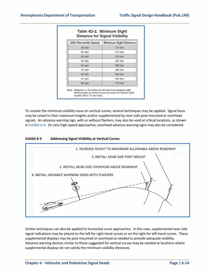
Pennsylvania Department of Transportation Traffic Signal Design Handbook (Pub.149)
Chapter 6 - Vehicular and Pedestrian Signal Heads Page | 6-14
To resolve the minimum visibility issue on vertical curves, several techniques may be applied. Signal faces may be raised to their maximum heights and/or supplemented by near-side post-mounted or overhead signals. An advance warning sign, with or without flashers, may also be used at critical locations, as shown in Exhibit 6-4. On very high-speed approaches, overhead advance warning signs may also be considered.
Exhibit 6-4 Addressing Signal Visibility at Vertical Curves
Similar techniques can also be applied to horizontal curve approaches. In this case, supplemental near-side signal indications may be placed on the left for right-hand curves or on the right for left-hand curves. These supplemental displays may be post-mounted or overhead as needed to provide adequate visibility. Advance warning devices similar to those suggested for vertical curves may be needed at locations where supplemental displays do not satisfy the minimum visibility distances.

Pennsylvania Department of Transportation Traffic Signal Design Handbook (Pub.149)
Chapter 6 - Vehicular and Pedestrian Signal Heads Page | 6-15
Driver expectancy of the signal location is particularly critical at horizontal curve approaches. At unlighted locations at night, the driver may not always perceive the proper travel path to the intersection. Shifting a primary signal face and/or installing supplemental faces to guide the driver into the intersection may be considered.
There are no formal guidelines for locating signals in such diverse situations. One method for determining the most effective layout is to drive the approaches at night to identify the exact point where driver confusion may arise. A plan view of the intersection is then drafted showing the lines of sight in relation to alternate signal head placement. A design layout is then developed using the "best" alternative and is reviewed in the field.
Exhibit 6-5 illustrates a layout with three possible supplemental signal locations. In this illustration, a and b represent additional signal head locations on a mast arm and c is a post-mounted near-right signal. Although positions a and b are the most conspicuous, they might tend to draw the driver toward the left of the curve, since drivers are accustomed to seeing the first signal (primary signal) on the right. Position c might be preferable in that it would tend to lead the driver around the curve.
Exhibit 6-5 Supplemental Signal Placements for Horizontal Curves
Pedestrian Hybrid Beacons
The Department does not currently allow implementation of this device, refer to Publication 46.
Traffic Control Signals and Hybrid Beacons for Emergency Vehicle Access
An Emergency Vehicle sign with an emergency signal ahead supplemental plaque should be placed in advance of all emergency-vehicle traffic control signals. At least one of the two required signal faces for each approach on the major street should be located over the roadway. Also, it should be noted thathybrid beacons for emergency vehicle access are not permitted.

Pennsylvania Department of Transportation Traffic Signal Design Handbook (Pub.149)
Chapter 6 - Vehicular and Pedestrian Signal Heads Page | 6-16
Section 4G of the MUTCD. Refer to Publication 46.
Traffic Control Signals for One-Lane, Two-Way Facilities
Section 4H of the MUTCD . Refer to Publication 46.
Traffic Control Signals for Freeway Entrance Ramp
Section 4I of the MUTCD . Refer to Publication 46.
Signals should be either a two-section signal face containing a red signal indication and a green signal indication or a three-section signal face containing a red signal indication, a yellow signal indication, and a green signal indication.
Traffic Control for Movable Bridges
The Department does not currently allow implementation of traffic control for movable bridges, refer to Publication 46.
Highway Traffic Signals at Toll Plazas
Please contact the Pennsylvania Turnpike Commission for these guidelines.
Lane-Use Control Signals
1) An engineering study should be conducted to determine whether static signs may be used or if control signals are necessary.
2) Pavement markings shall be used in conjunction with reversible-lane control signs.
3) Signal indications shall be in units with rectangular signal faces and have opaque backgrounds.
4) The color of signal indication shall be clearly visible for 2,300 feet.
5) Signal faces shall be located approximately over the center of the lane controlled, and shall be located in a straight line across the roadway approximately at right angle to the roadway alignment.
6) The bottom of the signal face shall be a minimum of 15 feet and a maximum of 19 feet above the pavement grade.
7) Signals shall be coordinated so that all the signal indications along the controlled section of roadway are operated uniformly and consistently and shall be designed to reliably guard against showing any prohibited combination of signal indications. (See MUTCD Section 4M.04 for list of prohibited combination signal indications.)
For further guidance refer to Section 4M of the MUTCD; Publication 46.
Pennsylvania Department of Transportation Traffic Signal Design Handbook (Pub.149)
Chapter 7 - DETECTION Page | 7-1
CHAPTER 7 - DETECTION
7.1 Vehicular Detection Vehicular detectors are devices that provide information such as the presence, occupancy, volume, and speed of vehicles to the controller.
Types and Functions of Vehicular Detectors
The designer should be careful to consider all manufacturer recommendations for detection equipment. Ensure that the specified equipment can accommodate the full function of the design and operational intent in all roadside environments.
Inductive Loop
Inductive loop detection involves the placement of a continuous length of wire in the pavement, a lead-in cable, and an amplifier to provide an input to the controller.
When a current is placed on the wire, the loop becomes a large inductor, creating a magnetic field around it. When a ferrous object, such as a car, passes over the loop, eddy currents, induced in the frame of the vehicle, cause a decrease in the inductance of the loop. The detector amplifier senses this decrease and translates it to a vehicle demand. There are two modes of operation for detectors: pulse and presence.
When the mode selection switch on the loop amplifier is set to the PULSE position, the detector provides one output pulse having a pulse width of 75 milliseconds to 150 milliseconds for each vehicle passing over a detection area. The pulse mode provides a locking call on the controller until serviced. Since long detection areas are of little advantage when pulse detection is used, pulse detection is typically associated with the less expensive short detection areas.
When the mode selection switch is set to the PRESENCE position, the detector provides one output pulse for each vehicle passing over the detection area, or an output for a minimum of 180 seconds for a vehicle stopped over the detection area. Presence detection is typically associated with long, stop line detection areas and non-locking operation, such as volume density.
Magnetic/Microloop
Magnetic detectors detect vehicles inductively by installing a transducer (microloop) under the pavement. Operation is similar to inductive loops.
Video
Video detection systems use video cameras rigidly mounted on traffic supports to detect vehicles. One video camera is capable of providing detection to several lanes of traffic for one approach and of providing demand and volume, simultaneously. Video detection systems require video detection cards in lieu of loop amplifiers.
Accurate detection requires that the system be able to operate successfully in all kinds of weather and under a variety of ambient light conditions. Although the capabilities of these systems have increased, certain conditions (such as heavy fog) and (washout caused from the sun aligned directly with the approach) may still produce detection problems. Proper configurations shall be drawn through the video detection software to establish the detection zones. These detection zones may be removed, replaced, or redrawn using the video detection software.

Pennsylvania Department of Transportation Traffic Signal Design Handbook (Pub.149)
Chapter 7 - DETECTION Page | 7-2
Video detection can be used successfully for actuation detection on any approach as long as the camera can be located to meet the following criteria:
1) The camera is mounted at a height of approximately 30 feet; a lower height where the camera is mounted on a mast arm is acceptable for stop line detection, and up to 100 feet upstream detection for approaches of 30 MPH or less.
2) At a mounting height of 30 feet, a detection zone may be placed as far as 300 feet from the camera. This horizontal to vertical ratio of 10 to 1 defines the maximum limit for reliable detection at lower mounting heights. Vertical curvature of the approach should also be considered.
Note: Trucks may block vehicles causing inefficiency in working as volume-density detector.
3) The camera is mounted such that the zone of detection is in view and the horizon is NOT in the view.
4) The camera is aligned with the lanes that are being detected with a head-on view of traffic as much as practical.
5) The selected zone of detection is not affected by occlusion.
6) The intersection should have adequate street lighting levels to assure that whole vehicles, not just their headlights, are detected at night.
Video detectors have a number of distinct advantages over traditional loop detectors. Among these advantages are:
1) The potential of rapid deployment.
2) Feasible to use as temporary detectors.
3) Can be used in locations when there is pavement deterioration.
4) Can be used for approaches that are on bridge decks or other structures.
5) Can be installed in construction zones when lane changes require detector reconfigurations.
6) Can be installed with minimum disruption to existing traffic (short-term or no lane closures).
7) Can be used for detecting vehicles that are not within right-of-way.
8) Cost may be lower than conventional loop detection, particularly on multi-lane approaches.
Video detection can also be characterized with some distinct limitations:
1) Good operation with video detection demands proper camera placement.
2) Good camera placement requires proper support structure.
3) Vision-based systems can be limited in poor lighting conditions and also by changing shadows casued by trees near an intersection.
4) Severe fog or precipitation and wind gusts can result in poor performance.
5) Cameras require periodic lens cleaning to maintain proper performance.
6) Routine maintenance for checking camera views and inspecting mounting connections.
7) Detection over extended distances may be substandard and should be considered when evaluating the product.

Pennsylvania Department of Transportation Traffic Signal Design Handbook (Pub.149)
Chapter 7 - DETECTION Page | 7-3
Microwave / Radar
Microwave/radar systems use sensors rigidly mounted on traffic supports to detect approaching vehicles based on the frequency of emitted microwaves. Microwave sensors can detect vehicles in pulse and presence mode. Microwave systems require interface boards/modules in lieu of loop amplifiers. This type of detection may be desirable to track vehicles through the intersection. Digital wave radar systems allow forcontiuous tracking of vehicles at an intersection and perform well under all weather and light conditions.
Other
Various other types of vehicle detection systems exist. Ensure that these systems have been approved by PennDOT before proceeding with their use.
Selection
Each detection type has advantages and disadvantages. Factors, such as size of detection area, number of approach lanes, pavement conditions, and average modes of travel (vehicles, trucks, bicycles), must be identified before design. Radar/microwave and video systems may have higher upfront costs but potentially need less maintenance and replacement.
Inductive loops have been the preferred method of detection due to its lower cost of installation, greater reliability, and flexibility in design.
Microloops may be used in lieu of inductance loops in situations such as limited right of way and poor pavement conditions. The field of one microloop is typically 6’x6’ but up to four can typically be wired in series per lead-in cable.
Video detection should be considered at larger intersections where it can be cost-prohibitive to install multiple inductive loops. The initial installation cost may be higher than loops but most video cameras are capable of multiple zones of detection.
Design and Placement of Detection Zones
There are two basic configurations of zones of detection which may be utilized:
a) Short zone
b) Long zone
Refer to TC-8806 (Detectors) of Publication 148 for inductive loop layout details and installation. The discussion below is generally relative to inductive loop detectors but may be considered for other types.
Short Zones
The short zone may be installed either alone, or in conjunction with other short zones to create a large detection area (see Exhibit 7-1). Sizing and layout criteria are as follows:
a) The length shall be 6 feet.
b) The minimum width shall be 5 feet.
c) The sides of the zone should be 3 feet from either edge of the travel lane.
d) For detection in advance of the stop bar, the location from the stop line is determined by the speed of approaching vehicles.
e) For sequential short zones, the detection area shall be comprised of four zones and shall be approximately 70 feet long. The first zone shall be placed so that it extends 3 feet beyond the

Pennsylvania Department of Transportation Traffic Signal Design Handbook (Pub.149)
Chapter 7 - DETECTION Page | 7-4
stop line. Additional distance beyond 3 feet would require district traffic engineer approval. The second, third, and fourth zones shall be sequentially spaced at 10 feet, 15 feet and 20 feet, respectively.
Short zones may operate in either the pulse mode or the presence mode.
Long Zones
The long zone is used to provide a large detection area with one zone. Each lane of a detectorized approach shall have a separate zone (see Exhibit 7-1, Exhibit 7-2, and Exhibit 7-3 of this publication). Sizing and layout criteria are as follows:
a) The maximum length shall be 50 feet.
b) The maximum width shall be 8 feet and the minimum 5 feet.
c) The sides of the zone should be a minimum of 2 feet from either edge of the travel lane.
d) The front edge of the zone may extend 3 feet beyond the stop line. Additional distance beyond 3 feet would require district traffic engineer approval.
e) Long zones shall operate in the presence mode only.
Modified Long Inductive Loop
The modified long inductive loop was devised to address the problem of adjacent lane detection in very high sensitivity inductive loop systems. The outer configuration of the loop is identical to conventional loops, but has a saw cut down the center. The loop consists of wire laid in a figure eight pattern in the saw cut, thus creating two narrow loops laid side by side (see Exhibit 7-1 of this publication). This winding pattern creates fields that cancel outside the perimeter of the loop and are enhanced within it. Modified long loops are more effective than conventional loops in the detection of small vehicles such as bicycles and small motorcycles. The procedures for sizing and layout shall be identical to those for both short and long conventional loops. Refer to TC-8806 (Detectors) of Publication 148 for additional loop patterns for small vehicles.
Detector Zone Design
The following represents various inductive loop sensor design options available to the designer. Note that zones of detection for other types of detectors should be designed in a similar fashion.
Option 1: Consists of sequential short loops for individual lane detection in either the pulse or presence mode. They may be wired either in series or parallel; however, best results are achieved when alternate loops are paired and wired in parallel to separate input channels. There is an added safety feature inherent to this option as, should one loop fail, detection is not completely lost. Although the initial cost is higher than that for long loops, maintenance is easier, as in case of damage, only a small loop need be replaced.
The short loops, like the long ones, are susceptible to detecting vehicles in adjacent lanes; however, they are more sensitive and are better suited for sensing small vehicles.
Option 2: Consists of a long loop 6 feet by 50 feet maximum for each approach lane. This enables individual lane detection in the presence mode. Although this loop is larger than the other options, its initial cost is the lowest as less lead wire and fewer junction boxes are required. Construction cost is lowest of all options. The disadvantages are that, should the loop break, all

Pennsylvania Department of Transportation Traffic Signal Design Handbook (Pub.149)
Chapter 7 - DETECTION Page | 7-5
detection for that lane is lost, and long loops are the least sensitive of all. When the sensitivity is increased, the loop becomes more susceptible to detecting vehicles in adjacent lanes.
Option 3: Consists of a modified long loop for each approach lane. Its operation is identical to that of Option 2. The major advantage of this option is that it is usually sensitive enough to detect bicycles and small motorcycles, yet it does not detect vehicles in adjacent lanes. Like Option 2, detection for an entire lane is lost should the loop be severed.
Option 4: Consists of one short loop per lane located in advance of the intersection based on normal approach speeds. This option, which operates in pulse mode only, is best suited for providing extension intervals on roads with higher travel speeds. They can also be used for individual lane counting and gap determination.
Option 5: Is basically the same as Option 4, except one intermediate loop is used for multilane detection instead of individual lane detectors. Construction is less expensive than Option 4; however, should breakage occur, detection on that approach would be completely lost.
Option 6: Is a single short loop per approach lane for use where a driveway is located between the intersection and the area of detection for Options 4 or 5. Traffic generated by the driveway would be unable to actuate its phase without the additional detectors placed near the stop line. A 6 feet x 6 feet calling detector shall be used in these cases.
Exhibit 7-1 Detection Options for Various Types of Detection

Pennsylvania Department of Transportation Traffic Signal Design Handbook (Pub.149)
Chapter 7 - DETECTION Page | 7-6
Exhibit 7-2 Detection Location Details for Various Approach Widths

Pennsylvania Department of Transportation Traffic Signal Design Handbook (Pub.149)
Chapter 7 - DETECTION Page | 7-7
Exhibit 7-3 Detector Location Details for Various Approach Widths

Pennsylvania Department of Transportation Traffic Signal Design Handbook (Pub.149)
Chapter 7 - DETECTION Page | 7-8
Loop Sensor and Saw Cut
Before design of the sensor, a field investigation should be made to determine the condition of the roadway pavement. If the pavement is badly damaged (rutted, cracked, broken, etc.), the pavement should be reconstructed prior to installing a sensor.
Junction Boxes
An inductive loop sensor should have a junction box located in its immediate vicinity out of the roadway area. Sensors shall be provided with a length of 1-inch diameter rigid conduit from the junction box or pole base just beyond the curb or edge of roadway under the finished pavement. The conduit carries the sensor wires from the saw slot in the roadway to the junction box or pole base, where the sensor wires are spliced to the lead in wires. Refer to TC-8806 (Detectors) of Publication 148 for more details on junction box and conduit use with inductive loop detectors.
7.2 Pedestrian Detection Pedestrian detectors are devices that notify the controller of the presence of pedestrians.
Push Buttons
The pedestrian push button is the typical detection device used for actuation of pedestrian timings. The device consists of a housing of high visibility with a 2-inch minimum diameter button. Optional features can include a latching LED confirmation light and confirmation tone. Push buttons should be located horizontally and vertical on a traffic signal support or an exclusive push button pole nearest to the crosswalk in accordance with the MUTCD , Chapter 4E, and TC-8803 of Publication 148.
If a history of visually impaired pedestrians is documented, the use of Accessible Pedestrian Signals (APS) should be provided. An APS can include locator tones, spoken WALK messages, and/or vibrotactile indications to assist the impaired pedestrians in safely traversing the intersection.
Consult the MUTCD sections 4E.09 to 4E.13 for guidance on APS.
Passive Pedestrian Detection
Detection systems that passively sense the presence and walking speed of pedestrians may be considered. Ensure that these systems have been approved by PennDOT before proceeding with their use.

Pennsylvania Department of Transportation Traffic Signal Design Handbook (Pub.149)
Chapter Chapter 7 - Electrical Distribution Page | 8-1
CHAPTER 8 - ELECTRICAL DISTRIBUTION
8.1 Controller Placement
148 and 408.
8.2 Conduit
Conduit Layout
The conduit layout should be designed to minimize difficulty in construction as well as maintenance of the traffic signal. Conduit runs should be run as straight as possible to minimize material and construction costs and to ease pulling the cables. The runs should also be routed around utilities. Since portions of the roadway may need to be closed during trenching for the conduit, major streets should be crossed by conduit only once, when possible.
A conduit shall be provided from each pole or pedestal foundation to another foundation or junction box. Conduits passing beneath the roadway shall have a junction box at each terminus except at the last point of a cable run where the conduit may terminate in the pole base.
The conduit shall be laid out so that the traffic signal controller is located at or near the center of the conduit layout. This enables the creation of two separate wiring systems, each handling about half of the signals at the intersection.
A separate conduit shall be installed for the electrical service cable and for street lighting.
Size
In general, conduit sizes of 2-inch diameter or greater are to be used for purposes of signalization or interconnection. Use of 1-inch diameter conduits will be allowed for the routing of detector leads through the curb into a junction box and for detector lead-in runs of two or less to the controller cabinet. 1-inch diameter conduit also may be used for service leads. The required conduit size is determined by the number and sizes of cable to be contained in the conduit. In no case during the traffic signal design should a conduit be filled to more than 40 percent. The fill areas are determined by adding the cross sectional areas of all cables to be contained in the conduit and comparing it to the 40 percent fill areas of the conduit. See Exhibit 8-1 and Exhibit 8-2 of this publication for an example of this analysis.
Note: When conduit is to be placed beneath the roadway, consider using either conduit of a larger diamter orplacement of a spare conduit for future expansion.
Of prime importance is the prevention of potential damage or knockdown of controllers by vehicular traffic. Controllers should not be located near the curb return or on channelization islands. Consider the position ofthe controllers door, it should not open into traffic. Additional considerations, such as the location of electrical service or communications lines and visibility of signal operations from the controller, should be taken into account. Ideally, maintenance personnel should be able to view at least one of the traffic signal indications for all operating phases while setting the timing or performing other tasks in the controller cabinet. Contact with the utility companies shall be made to determine how electric service will be provided, and field verification should be made to determine the design aspects of the electric service at the intersection location. Controller configuration shall be in compliance with Publications

Pennsylvania Department of Transportation Traffic Signal Design Handbook (Pub.149)
Chapter Chapter 7 - Electrical Distribution Page | 8-2
Exhibit 8-1 Conduit Fill Areas
Conduit --- 40% fill areas, in2
Type 1 in 2 in 3 in 4 in
Non-metallic* 0.29 1.18 2.64 4.65
Metallic 0.34 1.34 2.95 5.09
Note: * use these values for design purposes
Exhibit 8-2 Cable Areas
Number of Cables
Signal Cable Areas, in2
#12 AWG #14 AWG
3/c 5/c 7/c Lead-in 3/c 5/c 7/c Lead-in
1 0.145 0.212 0.273 0.116 0.107 0.152 0.180 0.093
2 0.290 0.424 0.546 0.232 0.214 0.304 0.360 0.186
3 0.435 0.636 0.819 0.348 0.321 0.456 0.540 0.279
4 0.580 0.848 1.092 0.464 0.428 0.608 0.720 0.372
5 0.725 1.060 1.365 0.580 0.535 0.760 0.900 0.465
Bare Copper Ground Wire - #8 AWG 1/c = 0.017 in2
Luminaire Cable #8 AWG 1/c = 0.058 in2
Coaxial Cable (RG-59/U) = 0.012 in2
Video Camera Power Cable - #16 AWG 3/c = 0.389 in2
Method of Installation
a) Trench - Conduits to be installed in developed areas may be installed by the open trench method. The trench shall be deep enough to provide a minimum depth of cover of 24 inches; a minimum depth of cover of 36 inches is recommended if conduit carries communications cable. Trenching shall meet the provisions of Publication 148 and Publication 408.
b) Jacking - In highly developed areas, under new pavements, or under major highways where the interruption of traffic is a critical concern, a jacking method (pre-approved by the Department) may be considered for the installation of conduit.

Pennsylvania Department of Transportation Traffic Signal Design Handbook (Pub.149)
Chapter Chapter 7 - Electrical Distribution Page | 8-3
c) Boring. Directional boring may be considered as an alternative to “trench and backfill” and “jacking”. The depth of borings should be below the existing roadway subgrade and should not cause any deformation of the roadway. For more information refer to Publication 14M, Section 954.3 (b).
8.3 Junction Boxes
Junction boxes are located at the juncture of two or more conduit lines. These boxes provide a point from where cables may be pulled through the conduit. All junction boxes shall meet the provisions of Publication 148 and Publication 408.
Description
All junction box installations of the various types consist of three basic components: box, cover, and coarse aggregate drain.
In paved areas, the cover shall be set flush with the finished grade of the sidewalk. In earth areas, it should be 1-inch above the surrounding grade.
Location
A junction box should be provided at the following locations:
a) On intersection corners where traffic signal poles are to be situated and underground cable runs continue to other supports.
b) Where detector sensors are spliced to lead-in wire.
c) In extremely long conduit runs, greater than 330 feet.
The facilitation of maintenance should be kept in mind when locating junction boxes. To this end, junction boxes in roadway areas and in driveway areas should be avoided.
Types
Several types of junction boxes are detailed in Publication 148 and Publication 72M (RC Standards). Publication 148 contains details for Type JB-26 and Type JB-27 junction boxes that are commonly used for traffic signals. The junction boxes detailed in the Publication 72M (RC Standards) [Type JB-1, Type JB-2, Type JB-11, Type JB-12] are used in general for highway lighting, but can be used for traffic signals if needed.
The following are guidelines to assist in the selection of junction boxes:
a) Type JB-26: Used for detector lead-in, only in areas not subject to vehicular traffic.
b) Type JB-27: Used for all other system distribution other than for detector lead-in, only in areas not subject to vehicular traffic.
c) Types JB-1 and JB-2: Used for all system distribution, only in areas not subject to vehicular traffic.
d) Types JB-11 and JB-12: Used for all system distribution in areas subject to vehicular traffic.

Pennsylvania Department of Transportation Traffic Signal Design Handbook (Pub.149)
Chapter Chapter 7 - Electrical Distribution Page | 8-4
As a general rule, the total cross sectional area of conduit entering a junction box should not exceed 15% of the area of the junction box. When this amount is exceeded a larger box should be considered.
8.4 Wiring
Conductors
The size of all signal wire shall be determined utilizing the method shown in Exhibit 8-1 and Exhibit 8-2 of this publication; #14 AWG shall be the minimum size.
Cable Selection
The number of conductors to be used for signal head wiring is determined by the number of indications to be displayed by the signal.
Each indication requires two conductors: an ungrounded conductor and a grounded conductor (neutral). Neutral returns in a signal head may be spliced together, thus the total number of conductors required equals the number of signal sections plus one. For example, a three-section signal head requires five conductors; a pedestrian signal requires three conductors, etc.
Cables should be selected such that the various sizes are reserved for specific applications. The following wiring applications shall be adhered to:
Use Minimum Conductor Size
Preemption Detector 3/c
Preemption Confirmation Light 3/c
Pedestrian Signal
3/c
5/c
5/c
7/c
Standardizing cable sizes for signal heads will yield at least one spare conductor for each signal. This will:
a) Reduce the number of different size cables to be purchased, which should result in reduced construction cost.
b) It allows for future expansion of the signal system to accommodate separate movements.
Consider providing a larger number of conductors to signal heads that may need to be replaced in the future with a signal head having more indications. For example, the left-most signal head on a mast arm may require a five-section signal head if a left-turn phase is anticipated in the future.
Wiring Method
Prior to determining the wiring required for a traffic signal design, the following must be prepared and completed:
a) Traffic signal layout with all signal heads numbered;
Five-Section Traffic Signal 7/c
Four-Section Traffic Signal
Three-Section Traffic Signal
Pedestrian Pushbutton

Pennsylvania Department of Transportation Traffic Signal Design Handbook (Pub.149)
Chapter Chapter 7 - Electrical Distribution Page | 8-5
b) Traffic signal operation chart; and
c) Conduit and junction box layout.
The following rules shall be adhered to when determining the required wiring:
a) Phase neutrals shall not be mixed;
b) Only those signals that display identical indications throughout the sequence of operations may have their wires terminated together.

Pennsylvania Department of Transportation Traffic Signal Design Handbook (Pub.149)
Chapter Chapter 7 - Electrical Distribution Page | 8-6
Exhibit 8-3 Conductor Size Worksheet

Pennsylvania Department of Transportation Traffic Signal Design Handbook (Pub.149)
Chapter Chapter 7 - Electrical Distribution Page | 8-7
Wiring Diagram
A schematic wiring diagram shall be prepared for each traffic signalization design location. This diagram shall show the controller, signal heads, detectors, pushbuttons, junction boxes as well as the required number, size, and types of wiring, and splices. An example of the diagram is illustrated in Exhibit 8-4 of this publication.
Color Codes
The individual conductors in a signal cable shall be color coded. These codes, for up to a seven conductor cable, shall be used as follows:
Conductor Color
1 Black Green Ball/Arrow, “WALKING PERSON” or WALK indication
2 White Neutral
3 Red Red, “UPRAISED HAND” or DONT
WALK indication
4 Green Reserved
5 Orange Yellow Ball/Arrow
6 Blue Green Arrow
7 White/Tracer Yellow Arrow/Spare
Detector Wiring
Loop detectors are wired through two cables – a loop sensor and a lead-in cable.
The loop sensor is installed in pavement surfaces through a saw-cut and covered with a sealant. The sensor must also lead to the junction box via a trench through a 1-inch conduit. The size of the loop detector determines the number of turns in the pavement.
The lead-in cable is spliced to the leads of the loop sensor and routed, via conduit, to the controller cabinet. Three splicing alternatives are approved by the Department.
a) Alternative A: The sensor cables and the lead-in cable are soldered together then covered first with wire nuts then immersed in an epoxy sealant.
b) Alternative B: The sensor cables and the lead-in cable are connected via insulated compression connectors then covered in two alternating layers of electrical tape and sealant.
c) Alternative C: The sensor cables and the lead-in cable are connected via insulated compression connectors then covered in a moisture-proof splicing kit.
Refer to Publication 148, TC-8806 for standard Detector drawings. For video or other methods of detection, follow the manufacturer’s recommended installation procedures.
Application

Pennsylvania Department of Transportation Traffic Signal Design Handbook (Pub.149)
Chapter Chapter 7 - Electrical Distribution Page | 8-8
Exhibit 8-4 Wiring Diagram

Pennsylvania Department of Transportation Traffic Signal Design Handbook (Pub.149)
Chapter Chapter 7 - Electrical Distribution Page | 8-9
8.5 Electric Service Three methods of providing electricity to the intersection are available.
a) Type A. Service is initially provided to a service (utility) pole. From the service pole, the service cable is routed through a 2-inch (minimum) conduit to the controller cabinet.
b) Type B. Applicable for both pole mounted or base mounted cabinets. Service is initially provided to a traffic signal support. From the signal support, the service cable is routed through
a 2-inch (minimum) conduit to the controller cabinet.
c) Type C. Service is provided directly from the utility to the controller cabinet via a 2-inch (minimum) conduit.
The selection of type should consider several factors such as area (urban, suburban, rural), right of way, and the proximity of controller cabinet to utility. Verify with the utility whether the intersection needs to be metered or unmetered. Refer to Publication 148, TC-8804 for standard Electrical Distribution drawings.

Pennsylvania Department of Transportation Traffic Signal Design Handbook (Pub.149)
Chapter 9 - Intersection Lighting Page | 9-1
CHAPTER 9 - INTERSECTION LIGHTING
The purpose of this Chapter is to provide guidance as appropriate for intersection lighting when installing traffic signals. Each proposed signalized intersection should be evaluated to determine whether intersection lighting is needed. Once a determination to install intersection lighting has been made, the appropriate lighting level should be established by referring to the design value tables in the latest American Association of State Highway Transportation Official’s (AASHTOs) Roadway Lighting Design Guide. The design value should be the sum of the recommended values for the two intersecting roadways. Additionally, Publication 13M (Design Manual 2), Chapter 5, Lighting should be evaluated appropriately. For complicated intersections, a qualified lighting engineer should design and/or review the intersection lighting to ensure adequate lighting levels are provided.

Pennsylvania Department of Transportation Traffic Signal Design Handbook (Pub.149)
Chapter 10 - Preemption and Priority Control Page | 10-1
CHAPTER 10 - PREEMPTION AND PRIORITY CONTROL
In addition to the materials indicated throughout this chapter, please consult the MUTCD, Section 4D.27.
Systems in which traffic control signals are preempted by an approaching emergency vehicle shall be designed and installed to provide a fail-safe indication to the driver of the approaching emergency vehicle when the equipment has preempted the traffic signal at that intersection. The fail-safe indication shall be a flashing white light on the street or approach on which the emergency vehicle is approaching.
Traffic signals operating during preemption conditions should be operated in a manner designed to keep traffic moving. The stopping of all traffic by the display of a steady All-Red is prohibited, except during normal clearance intervals.
10.1 Emergency Vehicle Preemption (EVP)
Types
Currently, emergency vehicle preemption systems use either optical, acoustic, or radio with global positioning system (GPS) technologies. When considering emergency vehicle preemption systems, it is important to evaluate the pros and cons of the various types of PennDOT-approved systems. Since emergency vehicles may cross municipal borders, it is also important to determine the type of preemption systems that adjacent municipalities use or plan to use in order to ensure the desired regional interoperability.
Optical Preemption Systems
Optical preemption systems have three basic components: 1) emitters that send the signal from the emergency vehicle to request the preemption; 2) detectors that receive the signal and send it to the controller; and 3) controller cards that process the signal, determine its validity, and initiate the preemption of all other signal functions. The emitters used in optical systems use light to inform the detector that a call has been placed at the signalized intersection.
Acoustic Preemption Systems
Acoustic preemption systems detect the sound from the siren of an emergency vehicle. Acoustic preemption systems do not require an optical emitter on the emergency vehicle, but it is desirable that all the types of sirens used by emergency vehicles be tested and the system be calibrated to help ensure that the desired performance is achieved.
Radio with Global Positioning System (GPS) Preemption Systems
Radio with GPS preemption systems have three basic components: 1) emitters that send the signal via radio from the emergency vehicle to request the preemption; 2) detectors that receive the signal and send it to the controller; and 3) controller cards that process the signal, determine its validity, and initiate the preemption of all other signal functions. The GPS feature monitors the movement of the approaching emergency vehicle and initiates the preemption phasing accordingly.

Pennsylvania Department of Transportation Traffic Signal Design Handbook (Pub.149)
Chapter 10 - Preemption and Priority Control Page | 10-2
Operation
Emergency vehicle preemption may occur during any interval of the normal controller operation. Depending upon the direction of travel of the emergency vehicle, one of the following phases (using NEMA phases) will be displayed: Phase 1+6, 2+5, 3+8, or 4+7. The system shall provide service on a first-come, first-serve basis. Once the first priority vehicle calls the system, it shall prevent other preemptive vehicles from entering calls until the first emergency vehicle releases control and clears the intersection.
The transition into and out of preemption as a result of a preemptive call being received during any interval of traffic signal operation shall be clearly defined in the Movement, Phasing, and Sequence Diagram; Emergency Preemption Phasing Diagram; and associated notes on the traffic signal permit. Care should be taken to avoid yellow traps, if practical. During the transition to preemption, the controller unit may stay in a normal sequence phase if that phase is also defined as a preemption phase. For example, if the traffic signal is in phase 1+6 green and that phase is the direction from which the preempting vehicle is approaching, the controller may stay in phase 1+6 without going through selective clearances.
Upon termination of the preemption phase, the controller goes to the pre-designated post preemption phase, then to normal “Phase Next” operation. Four options are available within most controllers in determining the post preemption phase:
a) Go to Exit Phase: The preemption phase and the post preemption phase may be as follows:
Preemption Phase Post Preemption Phase
1+6 2+6
2+5 2+6
4+8 2+6
2+6 4+8
As an alternative, the post preemption phase would be the major street green.
b) Go to Next Demand: The post preemption phase may be the phase immediately after the preemption phase during normal operation.
c) Resume Interrupted Sequence: The post preemption phase will be the phase that occurred before the preemption phase.
d) Exit to Coordination: The post preemption phase will be the phase that would have occurred to keep the signal in coordination within the system.
3+8 4+8
4+7 4+8

Pennsylvania Department of Transportation Traffic Signal Design Handbook (Pub.149)
Chapter 10 - Preemption and Priority Control Page | 10-3
10.2 Preemption Systems
Rail
Consult chapter 19 of this publication and the MUTCD, Chapter 8.
Where the distance between a traffic signal and a highway-rail grade crossing is less than 300 feet, rail preemption should be utilized to help avoid a potential collision between a vehicle which is queued on the tracks and the rail utility. An interconnection between the rail utility and the controller cabinet will be necessary. Rail preemption shall supersede emergency preemption.
Design of the rail preemption system involves determining the amount of time a queue of vehicles needs to clear the tracks before transferring right-of-way to the rail. The “Guide for Determining Time Requirements for Traffic Signal Preemption at Highway-Rail Grade Crossings,” (see Appendix D) adopted by PennDOT from the Texas Department of Transportation, should be utilized to calculate the proper clearances and to provide the rail utility with the correct distance for placing its actuators on its tracks. Typically, while the signalized intersection is preempted by the railroad, a non-conflicting phase is active. As provided within Publication 46, PUC coordination is required for all railroad preemption systems.
Transit
Transit priority preemption may be used for buses or light-rail services where the traffic signal can truncate opposing phases or extend phases concurrent with the bus/light-rail vehicle at a traffic signalized intersection. A predetermined amount of time, typically 5-15 seconds, shall be established. Transit priority shall not supersede emergency preemption. The effectiveness of transit priority should be evaluated and recommended in an engineering study and approved by the appropriate District Traffic Engineer prior to considering deployment.
Queue
Where queue spillback is a concern and deemed necessary to address with signal operations, queue preemption may be utilized. A detection zone should be utilized between the stop bar and the theoretical gore. If the detector is continuously occupied for a predetermined amount of time the signal may be preempted and the phase of concern will be activated. The detection zone location and occupancy actuation time should be approximated by factoring in the estimated queue discharge rate, vehicle headways, and average vehicle arrival rate so as to avoid the back of queue reaching the point of conflict. Typically, queue preemption systems are used at the end of limited access ramp sections where a concern with queue vehicles affecting the limit access facility exists.

Pennsylvania Department of Transportation Traffic Signal Design Handbook (Pub.149)
Chapter 11 - Systems Page | 11-1
CHAPTER 11 - SYSTEMS
The 2001 Traffic Control Devices Handbook published by the Institute of Transportation Engineers states:
“A traffic signal control system exists whenever two or more signals operate in a synchronous manner. The objective of a traffic signal control system is to improve the flow of traffic along a major street or throughout a network of streets. A traffic signal control major system consists of an appropriate signal-timing plan and the hardware components to implement that signal-timing plan. The signal-timing plan must satisfy traffic demand, traffic flow patterns and the geometrics that exist at each intersection and in the network as a whole.
Traffic signal control systems may be relatively small and simple or fairly large and complex. A system may merely consist of a series of intersections along a major street whose controller units are interconnected. Such a system’s purpose is to move platoons of traffic without interruption along the major street. On the other hand, a system may consist of a network of streets whose intersection controller units are centrally controlled by a digital computer with two-way communication between the computer and the intersection controllers. The purpose of this type of system is to reduce the total amount of delay and the total number of stops occurring to all traffic in the network.”
Refer to Chapter 3, Operational Requirements and Publication 46, Section 4.6, for information regarding traffic signal coordination, proper timing, and progression analysis procedures. Where the proximity between signalized intersections is such that traffic signal coordination is deemed appropriate and necessary, a system of traffic signals may be implemented. Historically, and currently, a reliable coordinated system can be achieved using a physical method of interconnection via some type of wiring or cable. More recently, technologies have become available that allow for the implementation of a system without physical means. The provision of traffic signals into a system is the focus of this chapter. Each type of system has its advantages and disadvantages that should be weighed by the designer while factoring in reliability, cost, and functionality.
11.1 Types
Time-Based Coordination (TBC)
The simplest form of coordination is the use of time-based coordination. The controller at each traffic signal must be equipped with an internal or external time clock to provide a point of reference (controller brands do not need to match). The primary disadvantage of TBC is that the time clocks may “drift” if not properly maintained. Over time small changes at each controller accumulate. Periodic resynchronization will be necessary. The use of GPS time clocks will generally eliminate this drift.
Interconnect
A communication link between two or more intersections has more long-term reliability for maintaining the coordination and efficiency of a system than TBC. Interconnect typically requires the use of a master controller, which can either act as a time clock synchronizer for all of the traffic signals in a system or send time-of-day patterns to each local controller. Methods of communication are discussed in Section 11.3.

Pennsylvania Department of Transportation Traffic Signal Design Handbook (Pub.149)
Chapter 11 - Systems Page | 11-2
Centralized/Closed Loop System
There are various types of centralized traffic signal systems that may be implemented. Types may range from large scale city grid systems that have proprietary customized software to smaller scale “off-the-shelf” PC-based arterial systems. A centralized system offers the capability to remotely monitor the individual intersection controllers, or groups of controllers. These systems are capable of communicating through a land line telephone drop or direct connection via fiber optic cable or wireless methods. The software is typically capable of viewing and editing timing patterns, viewing and storing traffic volumes, monitoring communication status, receiving maintenance alarms, etc.
Certain systems may offer traffic responsive program selections based on traffic demand. A group of pre-determined timing patterns may be stored in the system which can be selected based on traffic volume and occupancy thresholds.
Adaptive Signal Control
Adaptive signal control (ASC) is a type of traffic signal system that continually adjusts based on real-time traffic data in an attempt to provide the optimal traffic signal operation. Parameters, such as splits, permissives, and force-offs are adaptable within common controller brands; however, more advanced controllers are available. The use of ASC requires an extensive amount of detection to measure volume, occupancy, and/or queue lengths.
11.2 Design Considerations Several factors should be considered when determining which type of system to use, including but not limited to:
a) Cost b) Desired Functions c) Operation and Maintenance d) Corridor classification
TBC or a simple interconnect may be sufficient for isolated corridors with predictable traffic patterns. A centralized or closed loop system should be considered for major arterials and densely-populated areas that experience heavy volumes and daily volume fluctuations that may occur due to non-recurring congestion. Interconnected systems need to be monitored periodically to ensure that communications are operational. ASC should be considered as well for areas that experience major fluctuations in traffic demand, such as near interstates, shopping malls, sporting venues, etc. Buy-in and a financial commitment of operations and maintenance from the lead municipality must be obtained before proposing any type of system that requires periodic operations and maintenance.
11.3 Communications Three modes of communications are typically used to interconnect signals within a system. Refer to Section 953 (Traffic Signal Systems and Communications) of Publication 408 for specifics on the materials and construction methods.
Hard-wire Interconnect
Twisted-pair cable is generally installed in conduit between intersections.

Pennsylvania Department of Transportation Traffic Signal Design Handbook (Pub.149)
Chapter 11 - Systems Page | 11-3
a) Advantages
Least expensive method of physical interconnection, no additional equipment is required beyond the controller unit
b) Disadvantages
Conducts electricity which may cause lightning or power surge damage at multiple signal controllers
Fiber Optic Cable
Fiber optic cable can be installed aerially or in conduit between intersections. Care must be taken during design to specify the correct accompanying equipment as different types of fiber optic cable are available, i.e., single-mode vs. multi-mode, loose tube vs. tight buffered.
a) Advantages
Non-conductive (not susceptible to lightning strike travel), able to carry large amounts of data
b) Disadvantages
Cable difficult and exspensive to repair, accompanying equipment, and installation more expensive
Spread Spectrum Radio (SSR)
Communications between intersections is provided by a wide bandwidth frequency signal. Two frequency ranges are allowed, 902-928 MHz and 2.4 GHz, which do not require FCC licensing. An implementation survey will be required during design to determine if obstructions and/or roadway curvatures would require repeaters.
a) Advantages
No physical connection between intersections, lower cost
b) Disadvantages
Limited bandwidth compared to fiber, repeaters may be necessary.
Methods may be mixed within a system. For example, three intersections can be interconnected by fiber optic cable but a fourth may be interconnected by SSR due to an obstruction, such as a railroad overpass.

Pennsylvania Department of Transportation Traffic Signal Design Handbook (Pub.149)
Chapter 12 - Utilities Page | 12-1
CHAPTER 12 - UTILITIES
Coordination with utilities is essential for traffic signal construction projects. Aerial (overhead) utilities, such as electric, telephone, and cable lines, are typically attached to wooden utility poles. Underground utilities, such as gas, sewer, and water lines, can vary greatly in depth. All aerial and underground utilities must be verified and shown on the construction plans and the location and depth of all traffic signal support foundations and conduit must be designed accordingly. Additional utilities, such as railroad crossings must also be considered. Any time traffic signal equipment is installed under a crossing or attached to an overpass owned by a railroad, the PA Public Utilities Commission (PUC) must be contacted.
During design any impact on existing utilities must be assessed. Relocation can be expensive and time-consuming. For major projects with utility relocation, it is strongly recommended that the new utility locations be identified during the design phase. Refer to Publication 16M (Design Manual Part 5 – Utility Relocation) for information on utility relocation procedures.
12.1 Pennsylvania ONE-CALL System PA Act 121 of 2008 as amended requires designers to contact the PA One Call System whenever excavation is expected. To contact the system, dial 8-1-1. The signal designer must follow the PA One Call System regulations and policies. The system’s User’s Guide states “The designer shall make a reasonable effort to prepare the construction drawings to avoid damage to and minimize interference with a facility owner’s facilities in a proposed construction area.” Consult the system’s User’s Guide and other information related to designer responsibilities at www.pa1call.org.
When utilities are marked in the field they should follow ANSI Standard Z535.1 (Common Ground Alliance Best Practices for Temporary Marking). The colors and designations of the markings will be as follows:
12.2 PennDOT Utility Contacts
Color Designation(s)
White Proposed excavation
Pink Temporary survey markings
Red Electric power lines, cables, conduit and lighting cables
Yellow Gas, oil, steam, petroleum, or gaseous materials
Orange Communication, alarm or signal lines, cables or conduit and
traffic loops
Blue Potable water
Purple Reclaimed water, irrigation and slurry lines
Green Sewer and drain lines
For Department projects that require utility clearances, Exhibit 12-1 provides contact information for each district.

Pennsylvania Department of Transportation Traffic Signal Design Handbook (Pub.149)
Chapter 12 - Utilities Page | 12-2
Exhibit 12-1 District Utility Contact List
District Utility Coordinator Phone
District 1 Utility Coordinator (814) 678-7088
District 2 Utility Coordinator (814) 765-0449
District 3 Utility Coordinator (570)368-4254
District 4 Utility Coordinator (570) 963-4068
District 5 Utility Coordinator (610) 871-4437
District 6 Utility Coordinator (610) 205-6530
District 8 Utility Coordinator (717)705-2681
District 9 Utility Coordinator (814) 696-7214
District 10 Utility Coordinator (724) 357-2827
District 11 Utility Coordinator (412) 429-4949
District 12 Utility Coordinator (724) 439-7142
Central Office Utility Coordinator (717) 787-9661
12.3 Utility Information
Designers shall include utility locations on traffic signal construction plans. The presentation format shall follow Publication 14M (Design Manual Part 3 – Plans Presentation).
Utilities can be transmitted either aerially or underground. The lateral location as well as the height/depth is of importance when designing a traffic signal to avoid damage to the utility and the potential for interference.
Aerial
Overhead (aerial) cables are typically carried on wooden utility poles, which are owned and maintained by utility companies. Utility pole locations should be surveyed and shown on construction plans. It should be noted whether a pole is a joint pole or a non-joint pole. A joint pole will carry more than one facility (i.e., electric, telephone, and cable) while a non-joint pole is a dedicated pole with only one facility.
The utility pole carrying electrical service closest to the controller cabinet location should be selected for the electrical service point.
Underground
Several types of utilities, such as electric, potable water, and sanitary sewer, can be carried through conduit and pipes underground. A survey of manholes and junction boxes, as well as a PA One Call, is necessary to determine the location of all underground utilities. The depths of each utility will vary. Some projects may require Subsurface Utility Engineering (SUE).

Pennsylvania Department of Transportation Traffic Signal Design Handbook (Pub.149)
Chapter 12 - Utilities Page | 12-3
12.4 Required Clearances Refer to the National Electrical Safety Code (NESC), dated 2007 or as amended, for national clearance and installation standards. The standards of the local utilities present should also be referred to as they may be more stringent than the NESC. The lateral clearances from the utility lines to any traffic signal equipment must be met as well as vertical clearances between utility lines and mast arms and luminaries.
12.5 Overhead Clearances Clearance requirements are established in regards to equipment installed near overhead utilities. An Overhead Wire Clearance Plan of the lateral and vertical clearances may be prepared as an optional design tool. Refer to Exhibit 12-2 for an example.
Exhibit 12-2 Overhead Wire Clearance Plan

Pennsylvania Department of Transportation Traffic Signal Design Handbook (Pub.149)
Chapter 13 - Pavement Markings and Signs Page | 13-1
CHAPTER 13 - PAVEMENT MARKINGS AND SIGNS
13.1 Pavement Markings Provide pavement markings (such as centerline, channelization, stop lines, crosswalk lines, and lane control markings) as may be required to properly direct and control the flow of vehicular and pedestrian traffic through the signalized intersection.
Pavement markings shall meet the provisions of Publication 35 (a.k.a. Bulletin 15), Publication 46, Publication 111 (TC-8600 Series), Publication 212, and Publication 408.
For additional information consult the MUTCD Part 3, Markings.
13.2 Signs Signs provide proper direction and control the flow of vehicular and pedestrian traffic through the signalized intersection. Examples of such direction or control include turn prohibition, lane control, one-way, overhead street name, and pedestrian control. Refer to the MUTCD, Part 2, Signs for guidance on selection and placement of signs. All signs shall also meet the provisions of Publication 35 (a.k.a. Bulletin 15), Publication 46, Publication 111 (TC-8700 Series), Publication 212, Publication 236, and Publication 408. Note that the series numbers in Publication 236 supersede those of the MUTCD.
13.3 Illuminated Signs Illuminated signs may be used where an engineering study shows that reflectorized signs will not provide effective performance or where extraneous light makes it difficult to read reflectorized signs.
The traffic control signal shall be given dominant position and brightness to assure its target priority in the overall display.
Changeable message or blank-out signs may be installed where the message is applicable at specific times.
Internally illuminated street name signs may be used as preferred by the local municipality. Please refer to Publication 408, sections 936 and 1103.
For more information consult the MUTCD, Section 2A.07, Retroreflectivity and Illumination.

Pennsylvania Department of Transportation Traffic Signal Design Handbook (Pub.149)
Chapter 14 - Temporary Traffic Signals Page | 14-1
CHAPTER 14 - TEMPORARY TRAFFIC SIGNALS
Temporary traffic signals should only be used in situations where temporary traffic control signals are preferable. Refer to the MUTCD, Section 6F.84, Temporary Traffic Control Signals and Publication 213 for further guidance on when temporary traffic control signals are preferable to other means of traffic control.
14.1 Temporary Traffic Control Signal Requirements and Timeframes
Exhibit 14-1 Temporary Traffic Control Signal Requirements and Timeframes (from PATA 26e PL)
Type of Application Publication 213
Figure
PennDOT Approval Required Prior to
Use
Advance Site Visit Required by User
Application Required
Site-Specific Drawing Required
Deadline for District Receipt of All Required Materials
Long-Term Stationary Operation Fixed Supports
PATA 26e L X X X X At least 15 working days prior to
desired usage
Long-Term Stationary Operation Trailer-Mounted Portable Traffic
Control Signals PATA 26e L X X X X
At least 15 working days prior to desired usage
Short –Term Stationary Operation Pedestal-Mounted Portable Traffic
Control Signals Manually -Controlled PATA 26e M-1 X X X
At least 3 full working days prior to desired usage
Short –Term Stationary Operation Trailer-Mounted Portable Traffic
Control Signals Manually -Controlled PATA 26e M-2 X X X
At least 3 full working days prior to desired usage
Short –Term Stationary Operation Pedestal-Mounted Portable Traffic
Control Signals Non-Complex Conditions
PATA 26e NC-1 X X X At least 3 full working days prior to
desired usage
Short –Term Stationary Operation Trailer-Mounted Portable Traffic
Control Signals Non-Complex Conditions
PATA 26e NC-2 X X X At least 3 full working days prior to
desired usage
Short –Term Stationary Operation Pedestal-Mounted Portable Traffic Control Signals Complex Conditions
PATA 26e C-1 X X X X At least 15 working days prior to
desired usage
Short –Term Stationary Operation Trailer-Mounted Portable Traffic
Control Signals Complex Conditions PATA 26e C-2 X X X X
At least 15 working days prior to desired usage
Short –Term Stationary Operation Pedestal-Mounted Portable Traffic
Control Signals Blanket Permit X X X
At least 15 working days for initial blanket permit request; at least 3
full working days prior to each usage under the blanket permit
Short –Term Stationary Operation Trailer-Mounted Portable Traffic Control Signals Blanket Permit
X X X
At least 15 working days for initial blanket permit request; at least 3
full working days prior to each usage under the blanket permit

Pennsylvania Department of Transportation Traffic Signal Design Handbook (Pub.149)
Chapter 14 - Temporary Traffic Signals Page | 14-2
14.2 Process for Obtaining PennDOT Approval to Use Temporary Traffic Control Signals
14.3 Blanket Permits
What is a blanket permit?
a) For repeat users of portable traffic control signals, PennDOT’s appropriate Engineering District Office may issue a blanket temporary traffic control signal permit covering multiple locations and dates of operation for up to a one-year period. This action will only be considered by PennDOT if that user has properly used portable traffic control signals in a safe and efficient manner on three or more past deployments without problems and in compliance with PennDOT requirements.
b) PennDOT’s Bureau of Maintenance and Operations (BOMO) will be involved in the blanket permit process. Although permits are issued by the appropriate Engineering District Office, BOMO will participate in the evaluation process to determine whether a particular portable traffic control signal user can be issued their initial blanket permit in each Engineering District. BOMO will provide the overall blanket permit approval number, participate in any blanket permit revocation proceedings, and will keep track of users who have been issued blanket permits statewide.

Pennsylvania Department of Transportation Traffic Signal Design Handbook (Pub.149)
Chapter 14 - Temporary Traffic Signals Page | 14-3
What types of operations can be covered by a blanket permit?
a) Blanket permits can only be issued for short-term stationary operations (manual control or non-complex conditions) that satisfy the criteria and provisions of PATA 26e M-1, PATA 26e M-2, PATA 26e NC-1, or PATA 26e NC-2, except for emergency work as defined in PennDOT Publication 212. See Note 2 of each figure.
b) Blanket permits cannot be used for portable traffic control signal usage involving either long-term operations or short-term operations with complex conditions that are governed by PATA 26e PL, PATA 26e C-1, or PATA 26e C-2.
Who can apply for a blanket permit?
a) Any repeat user of portable traffic control signals who agrees to the responsibilities, terms, and conditions as outlined herein.
b) The blanket permit will be issued to up to two specific individuals (representing a company), and not to companies in general.
What are the roles and responsibilities of the blanket permittee?
a) Responsible for the proper installation, maintenance, and operation of the portable traffic control signal system as specified in Publication 213 and the temporary traffic control signal permit.
b) Work closely with the work crew to provide safe and proper operations as specified in Publication 213 and the temporary traffic control signal permit. Safety will be strictly enforced, and will not be compromised when using the devices.
c) Assist the work crew with Publication 213 and temporary traffic control signal permit requirements for portable traffic control signal usage.
d) Provide technical and expert assistance on the use of the devices before, during, and after deployments to the contractors’ personnel.
e) Take responsibility to ensure that the devices are working properly.
f) Approved products as specified in Publication 35 (Bulletin 15) must be used.
g) Ensure the upkeep of the devices to PennDOT specifications and requirements maintained by the Bureau of Maintenance and Operations (BOMO).
h) Provide documentation, satisfactory to PennDOT, showing that the individual successfully completed a training course given by the manufacturer on the operation of the portable traffic control signal system that is being deployed under the blanket permit.
i) Ensure proper all-red clearance intervals and yellow change intervals are used as specified in Publication 213 and the temporary traffic control signal permit.
j) Ensure appropriate green intervals are used based on traffic conditions. Ensure this is evaluated several times a day, and all changes should be documented.
k) Ensure that good records are kept of any changes during the operation of the devices.
l) Ensure that proper documentation is maintained on-site (including the temporary traffic control signal permit, Publication 213, etc.).

Pennsylvania Department of Transportation Traffic Signal Design Handbook (Pub.149)
Chapter 14 - Temporary Traffic Signals Page | 14-4
m) Develop and document a contingency plan by the permittee prior to the deployment of the devices to establish procedures in the event of device failure or malfunction, or in the event of changing conditions or unforeseen circumstances.
n) Provide the initial programming and the initial monitoring of the portable traffic control signals each day. All changes during the day should be made under the direction of the permittee and documented.
o) Be on-site at the start of signal usage each day. Provide emergency protocols and a contingency plan to address situations involving device malfunctions or changing conditions. Also, provide a direct number whereby the blanket permittee can be contacted at all times during signal usage.
p) Provide instructions to the work crew about proper removal procedures and how to place devices into a flash mode before going dark.
q) Visit the site in advance to ensure that proper usage can be achieved at the location of the upcoming deployment.
r) Continue to follow the appropriate processes outlined in Publication 213 for obtaining PennDOT approval to use portable traffic control signals. The deadline for PennDOT District Office receipt of all required materials for the blanket permit request is at least 15 working days prior to the first desired usage date. Thereafter, required materials must be received by the appropriate District Office at least 3 full working days prior to each usage under an established blanket permit.
s) Coordinate yearly with PennDOT’s Central Office and District Offices to ensure proper installations are occurring. Also, this will allow for a working relationship where the blanket permittee will be up-to-date with respect to the latest requirements and guidance documents.
What is the process/procedure to follow if an individual wants to be considered as a future blanket permittee?
a) Submit a written request to BOMO and the appropriate Engineering District(s) identifying the individuals seeking to be evaluated for future blanket permit consideration. Indicate the Engineering Districts where blanket permit consideration is being sought. Clearly indicate acceptance of the blanket permittee roles and responsibilities as outlined herein. Provide written documentation from the manufacturer of each portable traffic control signal system that will be deployed indicating that each individual seeking a blanket permit has successfully completed a training course given by the manufacturer on the operation of that signal system.
b) After receipt of the written request, PennDOT will contact the applicant to discuss the evaluation process and associated expectations. A series of successful trial deployments will need to be completed.
c) The appropriate processes outlined in Publication 213 for obtaining PennDOT approval to use portable traffic control signals must be followed for the trial deployments. Failure to do so may result in rejection of the trial deployment.

Pennsylvania Department of Transportation Traffic Signal Design Handbook (Pub.149)
Chapter 14 - Temporary Traffic Signals Page | 14-5
How many successful trial deployments must be completed before obtaining a blanket permit?
a) The initial application will begin the evaluation of the trial deployments. Previous deployments will not be considered during the blanket permit evaluation.
b) A minimum of three proper deployments by the individual desiring to be a future blanket permittee, with at least one proper deployment in each Engineering District where a blanket permit is desired.
c) PennDOT will allow a maximum of two individuals from the same company to be evaluated on each trial deployment for the purposes of being considered as a future blanket permittee.
d) BOMO will be actively involved in monitoring the trial deployments, and feedback received from District Office personnel, the work crew, the supplier/manufacturer, and others will be considered.
Upon successful completion of the trial deployments, what are the next steps?
a) PennDOT will document all comments and advise the applicant of successful completion of the trial deployments.
b) BOMO will work with District Office personnel to ensure that a blanket permit is issued to applicants that fulfill requirements.
What about blanket permit revocation?
a) A blanket permit must be renewed each year.
b) A blanket permit can be revoked at any time for poor performance by the Engineering District. BOMO will be involved in any revocation proceedings.
c) If a blanket permit is revoked, that individual will not be allowed to submit for a blanket permit application for at least one year. Future submissions should follow the same procedures as a first-time applicant.
14.4 Guidelines for the Selection of Temporary Traffic Control Signals in Work Zones For information consult the MUTCD Section 4D.32, Temporary Traffic Control Signals.
For all construction projects, a temporary traffic-control (TTC) plan must be included or referenced within the scope of the construction project plans. A TTC plan outlines the temporary traffic control measures which will be used for facilitating motorist or pedestrians through a work zone, incident, or other event which causes temporary interruption of normal road usage.
Key Terms and Definitions
Portable Traffic Control Signal- as defined in the MUTCD is a temporary traffic control signal that is designed so that it can be easily transported and reused at different locations. Types of portable signals are trailer-mounted and pedestal-mounted.
Temporary Traffic Control Signal on Fixed Supports – as defined in the MUTCD is a temporary traffic control signal that is temporarily mounted on fixed supports. They are typically constructed with span wires mounted on temporarily-installed poles.

Pennsylvania Department of Transportation Traffic Signal Design Handbook (Pub.149)
Chapter 14 - Temporary Traffic Signals Page | 14-6
Trailer-Mounted Portable Traffic Control Signal System – The system consists of two trailers, with each trailer having a vertical upright and a horizontal arm to accommodate the mounting of at least two signal heads.
Pedestal-Mounted Portable Traffic Control Signal System – The system consists of four units, with a pedestal-mounted signal head on each unit.
Automated Flagger Assistance Device (AFAD) – is a manually-controlled device operated by one or more individuals to safely stop and control traffic through a work zone.
Long-Term Stationary Operation – As defined in Publication 213 is work that occupies a location more than 24 hours.
Short-Term Stationary Operation – As defined in Publication 213 is work that occupies a location up to 24 hours.
Short-Term Stationary Operation for Temporary Traffic Control Signals – is defined as daylight work areas with work in active progress, emergency nighttime work areas with work in active progress, or work areas of relatively short duration where work begins during daylight and continues in active progress during hours of darkness.
Long-Term Stationary Operation for Temporary Traffic Control Signals - is defined as all other stationary operations that do not meet the short-term stationary operation for temporary traffic control signals criteria.
Signal Phase – the right-of-way, yellow change, and red clearance intervals in a cycle that are assigned to an independent traffic movement or combination of movements.
Two-Phase Traffic Signal Operation – is defined as an operation when two different vehicle movements occur during the signal cycle. One-lane, two-way traffic control is often a two-phase operation assuming that additional phases are not needed for driveways and intersecting roads.
Multiple Phase Traffic Signal Operation – is defined as an operation when more than two vehicle movements occur during the signal cycle.
Traffic Signal Timing – the amount of time allocated for the display of a signal indication.
Yellow Change Interval – is the first interval following the green interval during which the yellow signal indication is displayed. It is used to warn traffic of an impending change in the right-of-way assignment. The duration of a yellow change interval shall be predetermined.
Red Clearance Interval – is an interval that follows a yellow change interval and precedes the next conflicting green interval. It provides additional time before conflicting traffic movements, including pedestrians, are released. The duration of a red clearance interval shall be predetermined.
Temporary Traffic Control Signal Permit – is the PennDOT Engineering District Office acceptance that the proper documentation was received to ensure safe and effective use of temporary traffic control signals. This permit will allow proper use of the device in accordance with the provisions of the permit and Publication 213.
Temporary Traffic Control Signal Application – is an application that allows the PennDOT Engineering District Office to obtain the minimum required information to ensure safe and efficient operation of the temporary traffic control signal.
Site-Specific Drawing – A drawing that clearly depicts the work zone and the anticipated operations. Typically, this is part of the Traffic Control Plan (TCP). Performance Specification – Is the required product

Pennsylvania Department of Transportation Traffic Signal Design Handbook (Pub.149)
Chapter 14 - Temporary Traffic Signals Page | 14-7
performance, which may include but is not limited to equipment, physical requirements, operational requirements, etc...
Manually-Controlled Portable Traffic Control Signal Operation – when a portable traffic control signal is being controlled manually.
Short-Term Portable Traffic Control Signal Operation under Blanket Permit – this allows a successful past user of portable signals to obtain an agreement with PennDOT to provide notice of the placement of the portable signals with minimal documentation. Verification of the agreement between the user and PennDOT will be evaluated prior to approval of a blanket permit request.
Short-Term Stationary Portable Traffic Control Signal Operation for Non-Complex Conditions– the “non-complex” application will be verified through a number of physical and operational requirements that the site must meet to be considered. These checks allow PennDOT to verify safe and efficient use if installed properly.
Short-Term Stationary Portable Traffic Control Signal Operation for Complex Conditions– the “complex” application would be any short-term portable signal installation that does not met the requirements for “non-complex” applications.
Short-Term Emergency Operation – An emergency application defined in Pennsylvania Code Title 67, Chapter 212.
Long-Term Portable Traffic Control Signal Operation – All physical and operational requirements should be part of the Traffic Control Plan.
Temporary Traffic Control Signal – as defined in the MUTCD is a traffic control signal that is installed for a limited time period. Temporary traffic control signals may be portable or temporarily mounted on fixed supports. Common types of temporary traffic control signals are signals mounted on span wire with temporary supports and trailer mounted portable signals.
Work in Active Progress – Workers, other than flaggers, are present and are actively engaged in performing the necessary work
14.5 Temporary Traffic Control Signal - Documents Refer to Publication 213, Appendix A for the following documents related to the Temporary Traffic Control Signal application, compliance, operation, and approval:
a) Temporary Traffic Control Signal Permit or Temporary Traffic Control Signal Permit (fillable form)
b) Example Problem: Application For Permit to Operate Temporary Traffic Control Signals
c) Temporary Traffic Control Signals Non-Compliance Documentation Form
d) Temporary Traffic Control Signals User Comment Form
14.6 Operations In the design phase of every project that will have temporary traffic control signals, it is required that both installations on fixed supports and trailer-mounted portable traffic control signals always be considered before completing the design of the Traffic Control Plan (TCP). In some instances, trailer-mounted portable signals or installations on fixed supports can be used. On the other hand, in certain instances, installations on fixed supports may be preferable to trailer-mounted signals, or vice-versa, depending on the nature of the project, site conditions, traffic conditions, and other specific factors.

Pennsylvania Department of Transportation Traffic Signal Design Handbook (Pub.149)
Chapter 14 - Temporary Traffic Signals Page | 14-8
Before developing a TCP with temporary traffic signals, it is absolutely essential that the designer visit the proposed worksite beforehand. The site visit will enable the designer to evaluate various factors that will help in the determination of whether the TCP should permit both temporary signal design options, or one or the other. These factors include lateral clearance, trailer or pole placement, signal operation (phasing and timing), and others. Please also note that pedestal-mounted portable traffic control signals will not be considered for long-term stationary operations.
Good management principles should always be practiced by agencies administering roadway construction, maintenance, and utility operations. The application of the following good management principles outlined in Pennsylvania Code Title 67, Chapter 212, § 212.418 should be practiced:
a) Keep the temporary traffic-control zones as short as practical to avoid long stretches with no work activity.
b) Minimize lane restrictions.
c) Remove all traffic-control devices as soon as practical after the construction, maintenance or utility operation is complete.
d) Ensure structural adequacy of the temporary traffic control signal.
Long – Term Stationary Operations Using Temporary Traffic Control Signals on Fixed Supports:
Pros:
a) Desirable signal head placement can be achieved.
b) More than two overhead signals can be erected.
c) Less susceptible to vandalism.
d) Pole placement sometimes may be easier to accommodate than trailers due to physical features.
e) Fixed supports may be more desirable for long duration deployments.
f) More appropriate for multilane approaches.
g) Employs common traffic signal control equipment and operational features.
Cons:
a) Inability to set up and take down each day.
b) Less appealing for short-duration jobs or jobs with short-duration, multiple set-ups.
c) Equipment and material availability is sometimes an issue.
d) Less cost savings potential.
If the designer determines that only one temporary signal design option is justified for a particular project, then the TCP shall be prepared accordingly, and written documentation shall be maintained in the project file outlining the reasons for this determination. It would also be desirable to clearly indicate on the TCP that the other option will not be permitted for the project.

Pennsylvania Department of Transportation Traffic Signal Design Handbook (Pub.149)
Chapter 14 - Temporary Traffic Signals Page | 14-9
If the designer determines that trailer-mounted portable signals or installations on fixed supports would be acceptable, then the TCP should clearly show the exact design and operation of both alternatives so that additional plans from the contractor would not be necessary. The TCP should include the design of all anticipated needed features. For example, if platforms or other special features will be needed, their design and placement should be in the TCP. Engineering judgment should be used and documented to determine the safest and most efficient operation for the work zone.
Long – Term Stationary Operations Using Trailer-Mounted Portable Traffic Control Signals:
Pros:
a) Systems can be deployed quickly.
b) Especially conducive to deployments for emergencies.
c) Systems can be easily set up and taken down each day, or for multiple construction phases.
d) Equipment can be reused on future projects.
e) Equipment capable of being leased.
f) Cost savings potential.
g) Capable of wireless radio or hardwire interconnect.
h) Commonly equipped with monitoring system for location, low battery status, and conflicts using website and/or cell phone paging.
i) Commonly equipped with batteries that are solar recharging.
j) Commonly equipped with solar panels, rechargeable batteries, and ability to run via commercial power.
k) Wireless remote commonly available.
Cons:
a) Arm length can sometimes affect signal head placement.
b) Arm length affects number of signal heads that can be placed overhead.
c) Trailer size and/or arm length in conjunction with physical features can sometimes limit adequate placement.
d) Manufacturers have different operating systems.
e) More susceptible to vandalism.
f) Less appropriate for long-duration jobs on multilane, high-speed roadways.
Temporary Traffic Control Signals for Short-Term Stationary Operations
Before developing and/or determining your traffic control plan (TCP) using Publication 213, it is absolutely essential that the user visit the proposed worksite beforehand. The site visit will enable the user to evaluate various factors that will help in the determination of whether the TCP should permit temporary signal (portable signal) options, or other traffic control methods such as flaggers. These factors include lateral

Pennsylvania Department of Transportation Traffic Signal Design Handbook (Pub.149)
Chapter 14 - Temporary Traffic Signals Page | 14-10
clearance, trailer or pedestal placement, signal operation (phasing and timing), and others. Please also note that installations on fixed supports are not considered viable for short-term stationary operations because of the amount of time and materials needed for installation.
If the user determines that portable traffic control signals will be an option and would like to pursue that option, then a completed application shall be submitted to PennDOT’s appropriate Engineering District Office. If the Engineering District Office agrees with the proposed usage, they will issue a temporary traffic control signal permit.
14.7 Exceptions
Exempt Work
The use of temporary traffic control signals is not required for certain types of work. Common examples include: winter control operations, trash collection, street cleaning, traffic data collection, and etc. For more information on exempted types of work refer to Pennsylvania Code Title 67, Chapter 212, § 212.402.
Grade Crossings
Temporary traffic control signals should not be located within 300 feet of a grade crossing unless the temporary traffic control signal is in accordance with the MUTCD,Section 4D.27, Preemption and Priority Control of Traffic Control Signals or a uniformed flagger is provided at the crossing to eliminate vehicles form stopping within the crossing boundaries.

Pennsylvania Department of Transportation Traffic Signal Design Handbook (Pub.149)
Chapter 15 - Flashing Warning Devices Page | 15-1
CHAPTER 15 - FLASHING WARNING DEVICES For information not provided in this chapter consult the MUTCD, Chapter 4L, Flashing Beacons and Publication 46, Chapter 4, Flashing Beacons Guidance.
15.1 Intersection Control Beacon Intersection control beacons are typically installed at stop-controlled intersections with a documented history of crashes. Each approach to the intersection has one or more signal sections that flash either yellow or red as needed for proper control of the intersection, (i.e., the major street approaches generally flash yellow unless a multi-way stop is used).
15.2 Warning Beacon Warning beacons may be used for several types of applications as discussed in the MUTCD. Refer to Exhibit 15-1 for an installation detail. When using the configuration shown in Exhibit 15-1, the indications shall flash alternately. These indications may also be actuated so as to only flash when conflicting activity (pedestrians, bicycles, etc.) is present.
Exhibit 15-1 Flashing Warning Device Detail
Note: Foundations are required for all Flashing Warning Device structures, in compliance with Publication 148.

Pennsylvania Department of Transportation Traffic Signal Design Handbook (Pub.149)
Chapter 15 - Flashing Warning Devices Page | 15-2
15.3 Speed Limit Sign Beacon For speed limit sign beacons in proximity to school zones also consult the MUTCD,Section 7B.15, School Speed Limit Assembly (S4-1P, S4-2P, S4-3P, S4-4P, S4‑6P, S5-1) and
END SCHOOL SPEED LIMIT Sign (S5-3). Speed Limit Sign Beacons are typically installed with regulatory speed limit signs or school zone signs to command added attention. The beacons shall consist of two one-section signal heads with yellow circular indications aligned vertically on a speed limit sign and shall flash alternately. Refer to Exhibit 15-2 for the three options allowable for School Zone Speed Limit signs.
Exhibit 15-2 School Zone Speed Limit Signs
15.4 Stop Beacon Refer to the MUTCD, Section 4L.05, Stop Beacon.

Pennsylvania Department of Transportation Traffic Signal Design Handbook (Pub.149)
Chapter 16 - Plan Development Page | 16-1
CHAPTER 16 - PLAN DEVELOPMENT This chapter provides a basic guide for the development of traffic signal plans in Pennsylvania. First, a basic sequence of steps is provided for the designer to gain a general sense of the information needed and items to be considered while designing a traffic signal installation. The chapter will also present information related to traffic signal permit plans versus construction plans as well as tabulation sheets and computer aided drafting requirements.
16.1 Signal Plan Preparation Guide Although it may not be possible to strictly comply with the sequence indicated, this chapter will provide a systematic method to be used in preparing a plan. All critical design features and characteristics should be determined through an engineering study and engineering judgment. The preparation guide is a tool and should not supersede design features developed from the engineering study and engineering judgment. This procedure, when used in conjunction with the plan format checklists provided in this chapter and engineering study findings, helps ensure that the final product is a complete and concise plan for the installation of traffic signals. All designs should follow the general plan presentation requirements in Publication 14M (Design Manual 3).
Exhibit 16-1 STEP 1: Base Plan Preparation
Show curbing, shoulders, curb ramps, sidewalks, islands, pavement markings, and inlets on the base plan. The development of an accurate base plan should include a field survey performed by a surveyor so that the most accurate design can be made. Field verification of the site is strongly suggested prior to continuing the

Pennsylvania Department of Transportation Traffic Signal Design Handbook (Pub.149)
Chapter 16 - Plan Development Page | 16-2
design elements. If the project involves new construction, use care to ensure that the geometrics match those shown on the roadway plan.
Exhibit 16-2 STEP 2: Pavement Marking Layout
The roadway geometrics and lane configurations will either be based on existing conditions or proposed improvements that are based on previously completed capacity analysis and roadway design. Stop lines should be placed considering vehicular (truck or appropriate design vehicle) turning movements. The need for curb ramps and crosswalks should be determined through the engineering study taking into account Chapter 4 of this publication, Publication 13M (DM2) Chapter 6, and Publication 72M (RC Standards). Layout of crosswalks and curb ramps should be developed in concert with one another to provide the safe and efficient movement of pedestrians and vehicles through the intersection. The pedestrian accessible route should not be obstructed by poles, signs, hydrants, or other street hardware. The crosswalk should be a minimum 2 feet from the adjacent travel lanes. Pavement marking details shall follow Publications 46, Publication 111, Publication 408, and Pennsylvania Code Title 67, Chapter 212.

Pennsylvania Department of Transportation Traffic Signal Design Handbook (Pub.149)
Chapter 16 - Plan Development Page | 16-3
Exhibit 16-3 STEP 3: Location of Traffic Signal Supports
Follow the provisions of Chapter 5 of this publication while designing the location of supports. Signal supports should, whenever possible, be located behind the sidewalk area to minimize obstructions to pedestrians and vehicular traffic. Consider right-of-way lines, and select sites that will yield optimum visibility of signals to drivers and pedestrians, and are free from conflicts with utilities and drainage facilities. Supports shall also be provided in accordance with Publication 13M (DM2), Chapter 6 and Publication 72M (RC Standards) provisions.

Pennsylvania Department of Transportation Traffic Signal Design Handbook (Pub.149)
Chapter 16 - Plan Development Page | 16-4
Exhibit 16-4 STEP 4: Signal Heads and Pedestrian Accommodations
Locate the required positions of traffic signals in conformance with the provisions of the MUTCD and this publication. Provide mast arms, span wire, or pedestals for proper location of the signals. Using the signal templates, make sure the signals fall within the motorist’s cone of vision. Adjust the locations or add supplemental signals, if necessary. Based on the engineering study and engineering judgment, pedestrian signals, pushbutton locations, and additional accommodations shall meet the provisions of Publication 13M (DM2), Publication 72M (RC Standards), Publication 148, the MUTCD, and this publication. Also, if preemption was determined to be placed at the location, proper placement and capabilities should be determined prior to the device location finalization.

Pennsylvania Department of Transportation Traffic Signal Design Handbook (Pub.149)
Chapter 16 - Plan Development Page | 16-5
Exhibit 16-5 STEP 5: Location of the Traffic Signal Controller
Select a location for the controller. Of prime importance is the prevention of potential damage or knockdown by vehicular traffic. Controllers should not be located near the curb return or on channelization islands. Additional considerations, such as the location of electrical service or communications lines and visibility of signal operations from the controller, should be taken into account. Ideally, maintenance personnel should be able to view at least one of the traffic signal indications for all operating phases while setting the timing or performing other tasks in the controller cabinet. Contact with the utility companies shall be made to determine how electric service will be provided, and field verification should be made to determine the design aspects of the electric service at the intersection location. Controller configuration shall be in compliance with Publication 148 and Publication 408.

Pennsylvania Department of Transportation Traffic Signal Design Handbook (Pub.149)
Chapter 16 - Plan Development Page | 16-6
Exhibit 16-6 STEP 6: Location of Detection Areas
If the traffic signal installation under design is to be actuated, add detection of the sizes and types required in conformance with Publication 148, Publication 408, and this publication. For example, the detection zone should extend a minimum of 3 feet beyond the stop line. Detectors should be located a minimum of 3 feet from the centerline to minimize the possible detection of opposing or adjacent traffic. Avoid locating detectors where vehicles may park over them or near driveways to avoid false detections. Manholes or other subsurface structures which may affect the operation of the detectors must not be within the area of a loop detector. A series of smaller detection areas may be used to avoid subsurface structures and to provide the required area of detection.

Pennsylvania Department of Transportation Traffic Signal Design Handbook (Pub.149)
Chapter 16 - Plan Development Page | 16-7
Exhibit 16-7 STEP 7: Addition of the Electrical Distribution
Consult this publication for guidelines regarding the location of junction boxes, conduit, and electrical service conduit. Junction boxes should not be placed in curb ramps. Generally, there should be at least one junction box at each support where wiring runs continue to another location. Connect the junction boxes with a conduit system so the controller is near the center of the system, not at an end. To minimize obstructions to traffic during construction and to reduce costs, avoid placing conduit across both approaches of the major street. For detector leads, provide a conduit from the nearest junction box to the curb face. Add the conduit for electrical service. Prepare the wiring diagrams to indicate the size and number of conductors in each cable run.

Pennsylvania Department of Transportation Traffic Signal Design Handbook (Pub.149)
Chapter 16 - Plan Development Page | 16-8
Exhibit 16-8 STEP 8: Sign Placement
Add all regulatory and warning signs necessary to complete the design. The signs used must be designed and located in conformance with Publication 46, Publication 111, Publication 212, and Publication 236.
Complete the design by adding items such as dimensions, labeling of signal heads, poles, detectors, pavement markings, etc. Add the phasing and timing of signal operation as determined by an engineering study and engineering judgment. Diagrams showing all permissible and prohibited movements shall be provided for each phase. Separate intervals illustrating the displayed indication of each signal head shall be provided for each occurrence of a change of any displayed indication.

Pennsylvania Department of Transportation Traffic Signal Design Handbook (Pub.149)
Chapter 16 - Plan Development Page | 16-9
Exhibit 16-9 STEP 9: Development of a Tabulation Sheet
Complete the various tables on the tabulation sheet in conformance with the guidelines set forth in Publication 14M (Design Manual 3) to provide a complete and accurate listing of all construction items composing the traffic signal design. Complete the tabulation of the electrical distribution items from the wiring diagram. Finally, check both the plan sheet and tabulation sheet to ensure completeness and accuracy.
16.2 Plan Format Checklist The following checklist is to be used as a guide to prepare a permit plan sheet and/or the construction plans.
In general, the permit plan is used to show operational information and “above ground” traffic signal equipment, signs, and pavement markings related to the operational and safety aspects of the intersection. The roadway geometrics and all traffic control equipment should generally be presented on the permit plan as if they were existing features. The construction plan and tabulation sheet are primarily used as a tool for contractors to know what equipment and items are to be installed new and which items are preexisting that shall remain. The construction plan adds to the information provided on the permit plan by including conduit, junction boxes, controller cabinet, electrical service location, wiring diagram, pavement marking notes, utilities, contractor notes, and any other items specifically needed to relay the full intent of the construction scope of work to a contractor.

Pennsylvania Department of Transportation Traffic Signal Design Handbook (Pub.149)
Chapter 16 - Plan Development Page | 16-10
Plan Sheet
The information listed below is to be provided on both the permit plan and the construction plan unless indicated otherwise.
Sign Tabulation
Locate on lower left of sheet. Title. Column headings.
Plan symbol. Description. Size. Data Required Plan symbol beginning with letter "A". Description includes sign nomenclature from Publication 236 and actual legend. Size by width and height.
Movement, Phasing, and Sequence Chart
Locate on upper left of sheet. Designate the phases using NEMA phasing. See Chapter 3 of this publication or Appendix A for
examples. Diagrammatic representation of movements for respective phase, including pedestrian movements
with dashed lines. Beginning with 1, horizontally list the interval numbers for the cycle. Add preemption phases. Vertically list the signal head numbers as shown on the plans. For each interval, show the signal head display by indicating:
G for Green R for Red Y for Yellow W for “WALKING PERSON” indication or “WALK” indication H or DW for “UPRAISED HAND” indication or “DONT WALK” FH or FD for Flashing “HAND” indication or Flashing “DONT WALK” indication
for Green Arrow indication
for Yellow Arrow indication
for Red Arrow indication
At bottom of chart indicate the time settings for each interval, using the method indicated in Figure A-3 of this publication.
On right of chart, color the signals shall indicate when flashing. If not flashing, indicate "OFF". Indicate “Flash” (and hours of flashing). Show the required operational notes for controller operation. If railroad or emergency vehicle preemption is needed, add required phases and appropriate notes.
Phasing Diagram (Required only when sequencing is unusual or needs clarification.)
Locate next to phasing chart.

Pennsylvania Department of Transportation Traffic Signal Design Handbook (Pub.149)
Chapter 16 - Plan Development Page | 16-11
∅ symbol for phase. ← Indicate sequence of controller with arrows. ----- Symbol for phase sequence barrier. Number of various phases, using numbers 1, 2, 3 etc. (the NEMA standard). Letters (A, B, C) should
not be used.
Exhibit 16-10 Example Phasing Diagram (use standard NEMA phasing)
Signal Head Identification
Located at bottom middle of plan.
Vehicle Signals
Diagram of signal faces. Show signal numbers as they appear on the plans. Indicate colors and type.
R = red ball Y = yellow ball G = green ball = green arrow indication = yellow arrow indication
= red arrow indication Indicate size of signal.
8-inch signal 12-inch signal

Pennsylvania Department of Transportation Traffic Signal Design Handbook (Pub.149)
Chapter 16 - Plan Development Page | 16-12
Indicate type of visors. Indicate if backplates are to be installed. Indicate louvers (if required).
Pedestrian Signals
Diagram of signal faces. Show signal numbers as they appear on the plans. Indicate messages and location. Upraised hand indication Walking person indication Countdown digits indication
Indicate size of message.
Legend
Located at bottom right of page. Indicate all symbols here which appear on the intersection representation that need
explanation in addition to those indicated on the sample plan. After each symbol, give a definition of what it represents. Indicate existing equipment and items as hollow and/or with slanted text. Indicate proposed equipment and items as filled in solid and/or with upright text.
Title Block
Located at bottom right corner. Locate in the top quarter of the box the following categories: County: insert respective county Municipality: insert respective municipality Intersection of: insert street name/number of roads. Locate in the second quarter, the following: Approved By:________________________________ _______ Municipal Official Date Locate in the third quarter, the following: Recommended_______________________________ ________
District Traffic Engineer Date Locate at bottom quarter of box, the following: Scale: (Bar Type) either 1 inch = 20 feet or 1 inch = 25 feet.
For all of the above, the respective information must be filled in for each project.
Notes
Locate general notes on right hand side of sheet.
Signal Wiring Diagram (Construction Plan ONLY) Locate where able on sheet or place on additional sheet. Provide diagram of wire routing through the intersection. Indicate location of wire splices. Indicate wire conductor and size.

Pennsylvania Department of Transportation Traffic Signal Design Handbook (Pub.149)
Chapter 16 - Plan Development Page | 16-13
Upper Title Block
The following items should be located at the top right corner of the sheet, as required. Project data block (PENNDOT CONSTRUCTION PLAN ONLY)
District - indicate number. County - indicate county. Route - indicate the routes involved. Section - indicate section number. Sheet - indicate sheet number of contract plan set. Permit block (PERMIT PLAN ONLY)
Permit No. - indicate number. Date Issued - Date original permit was issued. Sheet ____of____- this is for this sheet number and for total number of sheets in permit. Revision block (PERMIT AND CONSTRUCTION PLAN).
Once plans have been approved, and changes are made, they should be indicated as follows: Revision number - indicate number (1, 2, 3, etc.).
Revision - indicate revision. Date - indicate date revision was made.
By - indicate who made revision.
Intersection
Located in center of sheet using scale of 1 inch = 20 feet or 1 inch = 25 feet. Plan view of intersection. North arrow.
(a) Show the following information on both the permit and construction plan: Curbs. Pavement markings. Supports. Signals with #'s. Pedestrian signals and pushbuttons with #'s or letter designation. Detectors with dimensions. Signs with letter designation. Right-of-way with dimensions and easements. SR, segment, and offset. Phasing symbols of each approach.
Lane widths Speed limit of each approach Average grades of each approach Nearest signal in each direction (or “no signal within one mile”) Municipal border if appropriate
(b) Plot the following proposed data on construction plan. Existing data as per Publication 13M (Design Manual 2). New curbs. Pavement markings (indicate existing versus proposed). Supports with pole #'s. Controller cabinet. Detectors with #'s.

Pennsylvania Department of Transportation Traffic Signal Design Handbook (Pub.149)
Chapter 16 - Plan Development Page | 16-14
Signs with letter designation (indicate existing versus proposed). Junction boxes with #'s. Conduit and its size. Electrical service location and type.
Tabulation Sheet
Prepare the following tabulations only for construction plans. Traffic Signal Supports
Location. Mast arms. Strain poles. Sign and signal locations. Item numbers.
Electrical and Conduit Items Location. Conduit. Trench. Signal cable. Junction box. Electrical service. Detector items.
Item numbers. Detectors
Amplifier. Description. Quantity. Location. Operation. Item numbers. Sensors. Description. Quantity. Size. Location. Item numbers.
Miscellaneous Item numbers. Controller assembly. Vehicle signal heads . Pedestrian signal heads. Systems. Communications. Preemption.
Pavement Markings Item numbers. Quantity. Description.

Pennsylvania Department of Transportation Traffic Signal Design Handbook (Pub.149)
Chapter 16 - Plan Development Page | 16-15
Signs Description. Size. Square feet. Item numbers. Sign Type/Mount.
Type B. Type F. Structure-Mounted.
16.3 Computer Aided Drafting (CAD) All signal plans shall be completed using industry standard computer aided drafting software. The electronic drawing file must be in MicroStation (dng) format and shall be provided to the Department prior to final approval of the design for both permit and construction plans. The file shall be organized with appropriate levels or layers to allow convenient isolation of title blocks, text, signal equipment, signs, MST diagram, sign tabulation, legend, proposed versus existing equipment, etc.

Pennsylvania Department of Transportation Traffic Signal Design Handbook (Pub.149)
Chapter 17 - Traffic Signal Design Report Page | 17-1
CHAPTER 17 - TRAFFIC SIGNAL DESIGN REPORT The traffic signal design report should generally follow the outline shown in Exhibit 17-1. Items not applicable to the project may be omitted. A brief description of each section follows the outline.
Exhibit 17-1 Traffic Signal Design Report Outline

Pennsylvania Department of Transportation Traffic Signal Design Handbook (Pub.149)
Chapter 17 - Traffic Signal Design Report Page | 17-2
Outline Definitions
Project Description
Provide a thorough description of the project so the reviewer can have a full understanding of the overall project intent and purpose, owner, location, scope, history and background, expected outcome, land uses in the vicinity, and any other information to help the Department fully understand the project.
Roadway and Traffic Data
a. Approach Geometrics Provide a description of the horizontal and vertical alignment of each intersection approach and, if needed, describe how it may specifically affect the signal design in an unusual way (sight distance, clearance times, etc.) b. Vehicular Volume Provide traffic volume data as necessary to show that the signal is warranted and for developing the timings to be used. Opening year traffic volumes should be used for proposed traffic signals and modifications to existing signals.
i. Existing Volume ii. Trip Generation iii. Projected Opening Year Volumes iv. Discussion of Vehicular Movement
c. Turn Lane Warrant Analysis Provide an analysis and discussion of turn lane requirements at the signalized intersection if required by the Department in accordance with Chapter 11.16 of Publication 46. d. Existing Signal and/or System If there is an existing traffic signal and/or interconnected system at the project intersection describe them in detail including existing operational features of the signal, condition of existing equipment, controller unit type and features, detection type, presence of emergency preemption, communication infrastructure type, system architecture (e.g. closed loop, central, GPS time-based, on-street master, etc.) e. Railroad Grade Crossings Discuss any nearby grade crossings that are included in the operation of the traffic signal. Provide information as discussed in Chapter 19 of this publication.
Pedestrian and ADA Accommodations
Provide a brief discussion of the results of the pedestrian study as completed per Chapter 4 of this publication and if/how pedestrians will be accommodated in the design of the traffic signal.
Traffic Signal Design
i. Timing and Phasing
i. Change and Clearance Intervals Provide a brief discussion on the completion of the CCIs. Provide the calculations in the report appendix.

Pennsylvania Department of Transportation Traffic Signal Design Handbook (Pub.149)
Chapter 17 - Traffic Signal Design Report Page | 17-3
ii. Left Turn Phasing Provide a brief discussion on the completion of left turn conflict factor analysis and its results as well as the recommendations for left turn phasing.
iii. Queuing Provide a brief discussion on the results of queuing analysis and existing and/or projected queues that may be of concern.
iv. Cycle Lengths Provide a brief discussion on existing (if appropriate) and proposed cycle lengths.
v. Pedestrian Timing Provide a brief discussion on the proposed pedestrian timings and any special features such as leading, lagging, or exclusive pedestrian phases, etc.
vi. Volume-Density and/or Indecision Zone Protection Provide a brief discussion on proposed volume-density and/or indecision zone detection including the design speed and how it is proposed to operate.
vii. Capacity Analysis and Level of Service Provide a discussion on the capacity analysis and its results including existing (if appropriate) and projected levels of service for the periods studied.
viii. Progression Analysis and System Engineering Provide a brief discussion on progression analysis that was completed for the project including existing (if appropriate) versus proposed green band efficiency (calculated as bandwidth divided by cycle length).
j. Equipment Placement Discuss the placement of signal equipment and any circumstances that would cause a reviewer to question the placement of signal supports and/or other equipment.
k. Modifications to Existing Intersections Provide a description of proposed changes to existing signal equipment.
Conclusion
Provide a concluding paragraph that summarizes the project and the final conclusions and recommendations for signalization under the project.
Appendices
a. Crash Data Analysis Provide an analysis of the previous three full years of crash data and how it relates to the traffic signal design. Discuss patterns that may be correctable through signalization and any anticipated adverse effects of signalization. b. Speed Data Provide a spot speed study in accordance with guidance in the Institute of Transportation Engineers’ Manual of Transportation Engineering Studies, 2nd Edition. The speed study results may be used for purposes of calculating change and clearance intervals as well as other settings such as advanced loop detection distances and lane shift tapers. c. Warrant Analysis Provide a brief summary of the warrant analysis that should have been completed during Step 1 of the traffic signal permit process (see Chapter 4 of Publication 46)
Provide all calculations, capacity analysis, intersection pictures, etc. in the appendices.

Pennsylvania Department of Transportation Traffic Signal Design Handbook (Pub.149)
Chapter 18 - Additional Design Considerations Page | 18-1
CHAPTER 18 - ADDITIONAL DESIGN CONSIDERATIONS
18.1 Design Considerations Based on Project Funding In general, traffic signal designs should not differ based on the project funding source. It is imperative that the safe and efficient movement of people and goods be the primary objective of every signal design. However, the project budget and installation costs should be of primary concern regardless of the project funding source. All factors such as safety, desired functionality, long term maintenance, installation costs, traffic control, constructability, etc. shall be considered during the design and approval process. Cost should not be a reason for leaving out important operational features of an intersection that may compromise safety or efficiency. Likewise, additional special features that are not needed to provide the desired functionality should not be required if they add substantial cost or if they are likely to not be maintained properly.
18.2 Special Provisions Special provisions for traffic signal projects should be written in accordance with Publication 51, Chapter 1, Section E, Special Provisions. Only items that are not standard Publication 408 items need a special provision. Consult the local PennDOT engineering district and/or central office to confirm if a standard special provision exists for an item that may be needed under a traffic signal design project.
For Traffic Signal items, please review Publication 46, Chapter 4 and complete TE-152 “Traffic Signal Proprietary Item Analysis Engineering and Traffic Study” prior to submitting for approval. Also District Traffic Engineer or designee approval is required prior to submitting to the Bureau of Maintenance and Operations.
18.3 Proprietary Equipment Approvals Consult Publication 46, Chapter 4, Section 4.7 regarding the process for requesting proprietary equipment approvals.
18.4 Municipal Traffic Signal Specifications Consideration shall be given to municipal traffic signal specifications during the design process. If a municipality has an adopted technical specification for traffic signal installations the designer and project owner should do their best to accommodate the municipality’s needs since the municipality is the permittee and ultimate owner of the traffic signal. Where proprietary equipment is a requirement, follow the process in Chapter 4 of Publication 46. Installation and long term maintenance costs as well as long term functionality must be considered when adhering to a municipal specification.

Pennsylvania Department of Transportation Traffic Signal Design Handbook (Pub.149)
Chapter 19 - Traffic Control Signals at or Near Railroad or Transit Grade Crossings Page | 19-1
CHAPTER 19 - TRAFFIC CONTROL SIGNALS AT OR NEAR RAILROAD OR TRANSIT GRADE CROSSINGS
19.1 General Consult the MUTCD, Sections 8C.09, 8C.10, and 8C.11 , Publication 371, and the Institute of Transportation Engineers’ Preemption of Traffic Signals Near Railroad Crossings, A Recommended Practice.
At some street and highway intersections, railroad tracks are within or near the intersection area; therefore, it may be necessary that the control of the vehicular traffic signals be preempted to avoid stopping vehicles on the tracks and to avoid the conflicting aspects of traffic signals and the flashing train approach signal. Such control must assure clearance of the tracks by all vehicular traffic before the arrival of the train at the crossing.
It is important to remember that these at-grade crossings come under the jurisdiction of the Pennsylvania Public Utility Commission (PUC) and any application or request for traffic control that may affect a crossing must be reviewed and approved by the PUC. In view of the PUC's jurisdiction over train approach signals, all designs for traffic signals at intersections within 300 feet of a grade crossing must be reviewed by the PUC before a permit for vehicular traffic signals may be issued by the Secretary of Transportation. Control of the traffic flow near the grade crossing should be designed to provide the vehicle operators using the crossing a measure of safety at least equal to that which existed prior to the installation of such signals. Accordingly, design, installation, and operation should be based upon a total systems approach in order that all relevant features may be considered.
When there are railroad or transit crossings at grade within 300 feet of the intersection, in any direction, the following information shall be submitted for any traffic signal request.
a) The name(s) of the railroad or others using the crossing.
b) The type of crossing (freight, shifting, spur, etc.).
c) The number of crossings per day.
d) The approximate time of crossing(s), or number per hour in case of a trolley crossing.
e) The average length of time it takes the train to clear the area of the intersection.
f) The type and operation of crossing protection presently in use. [If flashers, gates, bells, or combinations of these are present, determine the time element (maximum – minimum) that they are in operation prior to the time a train or transit vehicle reaches the crossing.]
g) The train speed on each approach to the crossing (track speeds).
h) The number and position of the tracks should be shown on the condition diagram.
19.2 Diagnostic Team A diagnostic team should be established at the beginning of the project prior to beginning design of the traffic signal. The team shall consist of all stakeholders involved in the design, approval, operation, and maintenance of the grade crossing and signal. At a minimum the team should include:
a) Design engineer
b) PennDOT representatives from all applicable units (Traffic, Utilities, Project Management, etc.)

Pennsylvania Department of Transportation Traffic Signal Design Handbook (Pub.149)
Chapter 19 - Traffic Control Signals at or Near Railroad or Transit Grade Crossings Page | 19-2
c) Operating railroad
d) PA Public Utilities Commission
e) Signal controller expert for the make and model to be used
f) Municipality (including the municipal traffic engineer)
g) Developer (if involved)
The purpose of the diagnostic team is to ensure the proper design and operation of the grade crossing and traffic signal by providing an opportunity for all stakeholders to provide input and relay concerns and technical details relevant to the installation and operation of the traffic signal.
The diagnostic team should meet at the project site during preliminary engineering. A sign-in sheet with each team member’s contact information should be gathered and distributed to the team.
Information that should be gathered from the diagnostic team includes, but is not necessarily limited to:
a) Signal controller operations
a. Preempt delay time,
b. Controller response time
b) Emergency flash operation
c) Type of train(s) using the crossing
d) Train speeds
e) Train frequency
f) Railroad timings
a. Gate delay
b. Gate descent
c. Gate down
g) Clearance/separation time
h) Advanced preemption time
i) Minimum walk time during right-of-way transfer
j) Pedestrian clearance time during right-of-way transfer
k) Crash history
19.3 Design It is important to note that coordination with the PUC and railroad is required during the design of the preemption system to the traffic signal.
When the grade crossing is equipped with an active traffic control system, the normal sequence of highway intersection signal indications should be preempted upon approach of trains to avoid entrapment of vehicles on the crossing by conflicting aspects of the highway traffic signals and the grade crossings signals. The preemption feature requires an electrical circuit between the control relay of the grade crossing warning system and the traffic controller. The circuit shall be of the closed circuit principle; that is, the traffic signal controller is normally energized and the circuit is wired through a closed contact of the

Pennsylvania Department of Transportation Traffic Signal Design Handbook (Pub.149)
Chapter 19 - Traffic Control Signals at or Near Railroad or Transit Grade Crossings Page | 19-3
energized control relay of the grade crossing warning system. This is to establish and maintain the preemption condition during the time that the grade crossing signals are in operation. Where multiple or successive preemption may occur from differing modes, train actuation should receive first priority and emergency vehicles second priority.
Where a signalized highway intersection is adjacent to a grade crossing not provided with an active traffic control system, the possibility of vehicles being trapped on the crossing remains and preemption of the signal controller is usually required. However, at some locations, the characteristics of the crossing and intersection area along with favorable speeds of both vehicular and train traffic may permit alternate methods of warning traffic. Where preemption of the traffic signal control is determined to be desirable, consideration should be given to the installation of active traffic control devices at the grade crossing, since the cost of the grade crossing devices would usually represent a minor addition to the cost of the railroad circuits required for the preemption function.
The preemption sequence initiated when the train first enters the approach circuit shall at once bring into effect a highway signal display which will permit traffic to clear the tracks before the train reaches the crossing. The preemption shall not cause any short vehicular clearances, and all necessary vehicular clearances shall be provided. However, because of the relative hazards involved, pedestrian clearances may be abbreviated in order to provide the track clearance display as early as possible.
To avoid misinterpretation during the time the clear-out signals are green, consideration should be given to the use of 12-inch red lenses in the signals which govern highway traffic movement over the crossing with adequately screened or louvered green lenses in the clear-out signals beyond the crossing.
After the track clearance phase, the highway intersection traffic control signals should be operated to permit vehicle movements that do not cross the tracks, but shall not provide a through circular green or arrow indication for movement over the tracks. This does not prohibit green indications for highway traffic movements on a roadway paralleling the tracks.
Where feasible, consider operating traffic control signals near grade crossings so that vehicles are not required to stop on the tracks, even though in some cases this will increase the waiting time. The exact nature of the display and the location of the signals to accomplish this will depend on the physical relationship of the tracks to the intersection area.
Highway traffic control signals shall not be used on mainline railroad crossings in lieu of flashing light signals. However, at industrial track crossings and other places where train movements are very slow (as in switching operations), highway traffic control signals may be used in lieu of conventional flashing light signals to warn vehicle operators of the approach or presence of a train. The provisions relating to traffic signal design, installation, and operation are applicable as appropriate where highway traffic signals are so used.
Calculations for determining the right-of-way transfer time, queue clearance time, maximum preemption time, warning time, track clearance time, and vehicle-gate interaction check should be completed using the worksheet and instructions provided in Appendix D from the “Guide for Determining Time Requirements for Traffic Signal Preemption at Highway Rail Grade Crossings”.
19.4 Plan Presentation The train preemption intervals should be shown in the regular Movement, Sequence, and Timing Diagram, and numbered sequentially. The preemption times should not be included in any coordinated programs that may be present at the intersection.

Pennsylvania Department of Transportation Traffic Signal Design Handbook (Pub.149)
Chapter 19 - Traffic Control Signals at or Near Railroad or Transit Grade Crossings Page | 19-4
A section of the traffic signal condition diagram should be reserved for Train Preemption Notes. This section should contain, at a minimum:
a) A note explaining which signals may remain green when going into train preemption.
b) A note explaining that the regular yellow and all-red intervals should time out before going into train preemption.
c) A note explaining the operation of the signal if preemption occurs during flashing operation.
d) A note explaining the operation of the pedestrian intervals.
e) A note explaining emergency preemption operation with train preemption.
19.5 Additional Considerations The installation of train preemption at a new or existing signalized intersection will require evaluation of the left-turns. Termination of one or more through phases at the beginning of train pre-emption may cause a left-turn trap to occur depending on the phase sequencing. Protected-only left turn phasing should be considered at these locations.
If the left-turn phase would not normally be warranted, Capacity analysis should be completed comparing intersection levels-of-service and delays with and without the left turn phase. If inclusion of the left-turn phase results in unacceptable additional intersection delays, the use of an W25-1 “Oncoming Traffic has Extended Green” sign should be considered in lieu of the left-turn phase.
Two Series R8-8 “Do Not Stop on Tracks” signs should be considered for each direction at each track crossing location. One should be placed before the crossing (or gates if present), and one after.

Pennsylvania Department of Transportation Traffic Signal Design Handbook (Pub.149)
Chapter 20 - Criteria for the Design of Traffic Signal Supports Page | 20-1
CHAPTER 20 - CRITERIA FOR THE DESIGN OF TRAFFIC SIGNAL SUPPORTS The criteria stated herein shall be utilized in the design of galvanized steel structures used for the support of traffic signals. This chapter is intended to define standard structural loadings for a typical mast arm; if a design is greater then what is provided then a special design is needed.
20.1 Design Criteria for All Support Structures
(See Section 20.2; "Design Criteria for Strain Poles,” for additional requirements for strain poles.)
Vertical poles and mast arms shall be designed and constructed in accordance with the 2001 AASHTO "Standard Specifications for Structural Supports for Highway Signs, Luminaires and Traffic Signals” including interim specifications (2002, 2003, and 2006), hereafter referred to as the "AASHTO Specifications.” In this part, the AASHTO Specifications article numbering system is followed. Where new sections, articles, equations, figures, or tables have been added, the suffix P is used to designate “Pennsylvania Article.” All references to the AASHTO Specifications sections, articles, equations, figures, or tables carry the prefix A, except where noted. References to the AASHTO Specifications commentary carry the prefix AC, except where noted.
a) Provide base and connection plates as indicated in PennDOT Publication 148; TC-8801 sheet 10 of 10.
b) Provide a complete joint penetration weld for the connection of the column or shaft to the base plate and the connection of the arm to the flange plate for mast arm and strain pole structures only (this is not a requirement for pedestal poles).
c) Attach a back-up ring as specified in the AASHTO Specifications (Table 11-2, Detail 11). The back-up ring shall be attached to the plate with a full-penetration weld or with a continuous fillet weld around the interior face of the back-up ring.
d) For pole diameters 18 inch and larger, seal the top of the backing ring with a continuous 1/8- inch fillet weld to seal off the area between the ring and the pole. For pole diameters less than 18 inch, seal the top of the backing ring with a continuous bead of caulk after galvanizing to seal off the area between the ring and the pole.
e) Provide 6 inch complete penetration longitudinal shaft welds at the base plate connection.
f) The use of mast arm plate socket connections with fillet welds are prohibited.
g) Provide welded connections as shown in PennDOT Publication 148; TC-8801 sheet 10 of 10.
h) The minimum thickness for the main column and mast arms shall be 3/16 inch (7 gauge). When the main column and mast arms are less than 5/16 inch, submit a non-destructive testing plan where UT testing is required to be performed to the Structural Materials Section, Bridge Design and Technology Division, Bureau of Project Delivery.
i) Provide a built-up box on columns with mating splice plate for mast arm connection as shown in Example 8 of Figure 11-1(c) in AASHTO Specifications. With prior Department approval, alternate mast arm connections as shown in the AASHTO Specifications (Example 16 of Figure 11-1(c)) are permitted.

Pennsylvania Department of Transportation Traffic Signal Design Handbook (Pub.149)
Chapter 20 - Criteria for the Design of Traffic Signal Supports Page | 20-2
Introduction
Applicable Specifications
The following shall replace the first sentence of A1.3.
The following specification documents shall be referenced for additional information on design, materials, fabrication, and construction:
The following shall supplement A1.3.
PennDOT Publication 408.
General Features of Design
Roadside Requirements for Structural Supports
Breakaway Supports
The following shall supplement A2.5.2.
Breakaway supports or yielding-type supports shall not be used for traffic signal support structures, except when permitted by this Handbook and specified in the plans and/or specifications for the project.
Loads
Dead Load
The following shall supplement A3.5.
Dead loads for signs, traffic signals, backplates, brackets, and all appurtenances shall be as given in this Handbook.
Live Load
Delete A3.6.
Wind Load
The following shall replace A3.8.
Wind load shall be the pressure of the wind acting horizontally on the supports, signs, luminaires, traffic signals, and other attachments computed in accordance with this Handbook and AASHTO Appendix C.
Steel Design
Details of Design
Slip Type Field Splice
The following shall replace A5.14.3.
Telescoping (slip-fit) splices for mast arms, which rely solely on friction between the members for their connection, will not be permitted. A thru-bolt must be provided for a positive connection when such slip fit connections are used.

Pennsylvania Department of Transportation Traffic Signal Design Handbook (Pub.149)
Chapter 20 - Criteria for the Design of Traffic Signal Supports Page | 20-3
Welded Connections
The following shall supplement A5.15.
Transverse welds shall not be used to splice pole sections.
Anchor Bolts
Design Basis
The following shall supplement A5.17.3.
A minimum of six (6) anchor bolts shall be required.
Bending Stress in Anchor Bolts
The following shall replace A5.17.6.4.
The clearance between the bottom of the leveling nuts and the top of the concrete foundation shall not be greater than one bolt diameter.
Minimum Protection for Structural Steel
General
The following shall replace the first sentence of A5.18.1.
Steel structures shall be protected from the effects of corrosion including those manufactured of high strength steel, by means of galvanizing in accordance with ASTM A 123 (AASHTO M 111). Accessories and hardware shall also be protected from the effects of corrosion by means of galvanizing in accordance with ASTM A 153 (AASHTO M 232).
Fatigue Design
Fatigue Importance Factors
The following shall supplement A11.6.
Traffic signal structures with mast arms less than or equal to 60 feet shall be designed for Fatigue Category II. Traffic signal structures with mast arms greater than 60 feet shall be designed for Fatigue Category I. Strain poles should be considered as an alternative to traffic signal structures with mast arms greater than 60 feet.
Fatigue Design Loads
Galloping
The following shall replace A11.7.1.
The dead load and wind surface area of a standard mitigation device shall be considered in the design of cantilevered traffic signal support structures in accordance with the standard drawings. The mitigation device should be installed only within the 180-day monitoring period in accordance with the standard drawings.
Truck-Induced Gust
Delete A11.7.4.

Pennsylvania Department of Transportation Traffic Signal Design Handbook (Pub.149)
Chapter 20 - Criteria for the Design of Traffic Signal Supports Page | 20-4
Design Aids
This section shall supplement AASHTO Appendix B.
Stresses for Tubular Sections
The following shall supplement Exhibit 20-1:
Maximum shear stress due to torsion (fvt) for round stepped tubes (hot-swaged shrink fit) shall be computed using the following formula:
t R k M f t z
vt 2 28 . 6 =
Where: fvt = Maximum shear stress due to torsion, lb/in2
Mz = Total torsional moment, in-lb
R = Radius at mid-thickness of smaller diameter tube wall, in
t = Thickness of smaller diameter tube wall, in
kt = Stress concentration factor due to change in tube diameter (use kt = 1.20)
Alternate Method for Wind Pressures
This section shall supplement AASHTO Appendix C.
Wind Load
The following shall replace the second sentence of the first paragraph of C.2:
The design wind pressures shall be computed using the wind pressure formula, Eq. C-1, for a fastest-mile wind speed (Vfm) of 80 MPH as shown in Figure C-3.
20.2 Design Criteria for Strain Poles (See Section 20.1; "Design Criteria for All Support Structures," for additional requirements.)
Allowable Unit Stresses
The design and construction of strain pole structures shall conform to the allowable unit stresses provided in Section 5 – Steel Design in the 2001 AASHTO "Standard Specifications for Structural Supports for Highway Signs, Luminaires and Traffic Signals", hereafter referred to as the "AASHTO specifications."
Span and Tether Wires
Span wire shall conform to ASTM A 475, Class A, Siemens-Martin Grade, or ASTM B 416. Tether wire shall conform to ASTM A 475, Class A, Common Grade.
Strain poles shall be designed for a sag of 5% of the span distance between poles under dead load. In computing dead load, the mass of the span and tether wire shall be based on a value of 1 lb/ft [load=1 lb/ft].

Pennsylvania Department of Transportation Traffic Signal Design Handbook (Pub.149)
Chapter 20 - Criteria for the Design of Traffic Signal Supports Page | 20-5
Strain Pole Deflection
The maximum horizontal deflection of strain poles, at the span wire connection, due to dead loads only, shall be 2.5% of the distance measured from the base of the strain pole to the span wire connection point.
When strain poles support more than one span, the resultant horizontal deflection, due to the combined action of all span wire loadings, shall not exceed the above.
Stringing Tension
To determine the stringing tension in the span wire system between the two strain poles, due to the dead loads of traffic signals, traffic signs, signal wire, and other attachments, the following procedure1 shall be used:
a) Determine the effective load of each item on the span wire (traffic signal, traffic sign, signal wire, and/or other attachment) by adding to the load of each item, the load of the span wire for a length equal to half the distance in each direction to the next adjacent item or strain pole.
b) Determine the vertical reaction at each strain pole structure by summing the moments (due to the effective load of each item and the vertical reaction at the strain pole) about the other strain pole structure. As a check, the sum of the vertical reactions of the two strain pole structures should be equivalent to the sum of the effective loads of each item.
c) Determine the lowest point due to sag in the span wire by finding the point at which the slope of the span wire changes sign (which will be at the location of one of the load items, most probably a traffic signal). Beginning with the vertical reaction at one of the strain pole structures, determine the vertical shear acting on the span wire by successively and algebraically adding the effective load of each item in moving across to, and ending with the vertical reaction of, the other strain pole structure. The low point in the span wire is the point at which the sign of the vertical shear changes (which indicates that the slope of the span wire has changed). If the vertical shear happens to be zero at any point between the strain pole structures, this indicates that two load items are at the same elevation and share the low point of the span wire. As a check, the vertical shear must begin and end at zero at the constituent strain pole structures.
d) Determine the stringing tension by evaluating the summation of moments about the low point in the span wire. Since the span wire cannot resist bending moment, set the sum of the moments about the low point of all forces acting on the span wire between the low point and either of the strain pole structures equal to zero, where the horizontal pull acting on that strain pole structure is an unknown force acting at a distance equal to the maximum allowable sag (5% of the span distance) above the low point of the span wire. The stringing tension in the span wire can then be determined by solving the aforementioned summation for the unknown horizontal force acting on each of the strain pole structures.
e) In the case where a strain pole structure supports wires and loading from more than one span, determine the stringing tension of each span wire that it supports, and combine these separate stringing tensions to produce the maximum resultant stringing tension acting on the given strain pole structure to evaluate the required design and construction considerations.

Pennsylvania Department of Transportation Traffic Signal Design Handbook (Pub.149)
Chapter 20 - Criteria for the Design of Traffic Signal Supports Page | 20-6
Sag
To determine the sag at any load item on the span wire, assume that the span wire follows a straight line between adjacent load items which slopes at a rate equal to the vertical shear at the given load item divided by the horizontal stringing tension. The change in elevation between successive load items is then equivalent to the slope of the span wire between these two load items multiplied by the distance between them. As a check, the elevation of the span wire connection at the second strain pole structure must be obtained by beginning with the connection at the first strain pole structure and successively adding the respective elevation increments in moving across the span wire.
Application of Wind Load (see Figure B-1)
Wh for strain pole structures may be applied as a series of concentrated loads along the span wire normal to the span, and Wp (normal to sign faces) shall be applied normal to the span. Strain poles (assuming a single span wire is attached to the support) shall be designed for wind loads Wh and Wp, (normal to the sign faces) applied normal to the span. Only the wind load, Wv, shall account for wind from any direction. The basic load, BL (see Section 3.9.3 of the AASHTO specifications) normal to the span shall be the effect from the wind load Wv, applied at the center of pressure of the support. The full transverse component shall be applied to the support.
Design Tension
For a strain pole structure with the ends of the span wire at the same elevation, the following approximate method may be used to determine the force component in the span wire parallel to the span for a wind loading normal to the span.
The span wire loadings (dead load, wind, and ice) are applied as a series of concentrated loads along the wire to represent the actual uniform loadings with a minimum of five equal concentrated loads recommended. The tension forces throughout the wire now become a series of vectors with the vector component in the direction of the span of equal magnitude for each vector. Knowing that the ratio of the vector length over the vector force is proportional to the ratio of the vector component length over a component force, the length of each vector may be expressed by the following equation:
Fx = Vector force component in direction of span
Fy = Vector force component in vertical direction
Fz = Vector force component in direction of wind
dx = Vector length component in direction of span* (* If sag is small in relation to span length, neglect any displacements in direction of span.)
Fy and Fz for each vector (between concentrated loads of wire, signals, signs, etc.) may be found by the equations of equilibrium for a body in space. The total length of the span wire may be found for a given sag for a loading of dead load alone. The sum of all the vector lengths is equated to the total length of the span
( )x
xzy FdFFF 222
x gthVector Len ++=
( ) force vector Resultant
:ereWh
222x =++ zy FFF

Pennsylvania Department of Transportation Traffic Signal Design Handbook (Pub.149)
Chapter 20 - Criteria for the Design of Traffic Signal Supports Page | 20-7
( ) ( ) ++++++=x
xzy
x
xzy F
dFFFFdFFF 22
222
2x
121
21
2x wirespan of
length totalThe
wire. Fx may be solved for since it is the only unknown in the equation. A number of trials may be necessary to closely approximate the actual value.
The following illustrates a procedure for determining the vector components Fx and Fz:
In Exhibit 20-1:
Exhibit 20-1 Force Diagram

Pennsylvania Department of Transportation Traffic Signal Design Handbook (Pub.149)
Chapter 20 - Criteria for the Design of Traffic Signal Supports Page | 20-8
The reactions Rz(L) and Rz(R) may be determined by summing moments about a vertical line at the right end and left end of the span wire respectively. A similar procedure is used in determining Fy components. The reactions in the vertical direction (Ry(L) and Ry(R)) may be determined by summing moments about a horizontal line to the ends of the span wire.
The above procedure neglects the effect of the strain pole deflection. This results in excessively conservative values for the wire's force component in the direction of the span (Fx). The effects of the strain pole deflections on the span wire's force component should be considered by calculating the deflections of the strain pole at the span wire connection, in the direction of the span, and recomputing the wire's force component, as above, after making adjustments to the span to account for the strain pole deflections. The reduction in tension does not apply to dead load tension. Given the wire is installed with the specified sag after the pole dead load deflection already has occurred, the wire tension is not reduced.
Design Stresses
Strain pole structures shall be designed and constructed to withstand maximum stresses based on Group I, Group II, and Group III loadings (whichever controls), as defined in the AASHTO specifications. In the case of strain poles which support more than one span, the resultant of the respective tensions for each span shall be used in combination with the wind applied in the direction which produces maximum stress.
20.3 Acceptance of Structural Designs The manufacturer shall submit design calculations and detailed structural drawings for those signal supports that are proposed to be supplied in Pennsylvania. In addition, the manufacturer must provide PennDOT with certification, from a professional engineer registered in Pennsylvania, indicating that the designs comply with PennDOT’s criteria and are adequate to support the loads specified therein.
After acceptance by the PennDOT, the manufacturer will not be required to submit design calculations or structural drawings on a project-by-project basis, except for signal supports which exceed the standard structure loadings indicated herein. For these special designs, a submission of design calculations, structural drawings and the professional engineer's certification must be made for each different support.
Shop drawings will be required for all traffic signal supports on each project (PennDOT Approved Shop Drawings).
For structural design computations use PennDOT’s District Design spreadsheets which include:
Mast Arm Analysis provides a tool to evaluate whether a traffic signal complies to loading requirements specified within Publication 149, Chapter 20 and TC-8801. If the loading is exceeded within this spreadsheet then a special traffic signal structural support and foundation design would be needed.
Span Wire Analysis provides a tool to determine the appropriate span wire tension by providing geometric specific information. This will ensure that appropriate design tensions are used for span wires.
Strain Pole Analysis provides a tool to evaluate whether a traffic signal complies to loading requirements specified within Publication 149, Chapter 20 and TC-8801. If the loading is exceeded within this spreadsheet then a special traffic signal structural support and foundation design would be needed.

Pennsylvania Department of Transportation Traffic Signal Design Handbook (Pub.149)
Chapter 20 - Criteria for the Design of Traffic Signal Supports Page | 20-9
Exhibit 20-2 Strain Pole Structure

Pennsylvania Department of Transportation Traffic Signal Design Handbook (Pub.149)
Chapter 20 - Criteria for the Design of Traffic Signal Supports Page | 20-10
Exhibit 20-3 Mast Arm – Standard Structure Loading

Pennsylvania Department of Transportation Traffic Signal Design Handbook (Pub.149)
Chapter 20 - Criteria for the Design of Traffic Signal Supports Page | 20-11
Exhibit 20-4 Mast Arm – Standard Structure Loading Tables
Note: For standard structure loading, place indicated signals and signs beginning at the furthermost point on the arm and then proceeding toward the shaft in accordance with the dimensions shown on Exhibit 20-3 and Publication 148, TC-8801.
Mast Arm Length (0-10 ft.)
Signals Signs
Max Y (ft)
M N O P Q R S T U V Y
W 70 123 39 87 5.2
A 8.76 8.82 7.48 10.5
Mast Arm Length (>10-15 ft.)
Signals Signs
Max Y (ft)
M N O P Q R S T U V Y
W 70 123 39 39 106 6.6
A 8.76 8.82 7.48 7.48 21.33
OR
W 70 123 39 106 9.5
A 8.76 8.82 7.48 21.33
Mast Arm Length (>15-20 ft.)
Signals Signs
Max Y (ft)
M N O P Q R S T U V Y
W 97 70 123 39 39 106 6.6
A 13.89 8.76 8.82 7.48 7.48 21.33
Mast Arm Length (>20-25 ft.)
Signals Signs
Max Y (ft)
M N O P Q R S T U V Y
W 97 70 123 39 39 39 106 8.5
A 13.89 8.76 8.82 7.48 7.48 7.48 21.33
W= Load in (lb) A=Area in (ft2)

Pennsylvania Department of Transportation Traffic Signal Design Handbook (Pub.149)
Chapter 20 - Criteria for the Design of Traffic Signal Supports Page | 20-12
Mast Arm Length (>25-30 ft.)
Signals Signs
Max Y (ft)
M N O P Q R S T U V Y
W 97 70 97 123 39 39 39 106 8.5
A 13.89 8.76 13.89 8.82 7.48 7.48 7.48 21.33
OR
W 97 70 123 39 39 39 106 13.5
A 13.89 8.76 8.82 7.48 7.48 7.48 21.33
Mast Arm Length (>30-35 ft.)
Signals Signs
Max Y (ft)
M N O P Q R S T U V Y
W 97 70 97 123 39 39 39 39 106 10.8
A 13.89 8.76 13.89 8.82 7.48 7.48 7.48 7.48 21.33
Mast Arm Length (>35-40 ft.)
Signals Signs
Max Y (ft)
M N O P Q R S T U V Y
W 97 70 70 97 123 39 39 39 39 106 7.9
A 13.89 8.76 8.76 13.89 8.82 7.48 7.48 7.48 7.48 21.33
OR
W 97 70 70 70 123 39 39 39 106 10.8
A 13.89 8.76 8.76 8.76 8.82 7.48 7.48 7.48 21.33
OR
W 97 70 97 123 39 39 39 39 106 15.7
A 13.89 8.76 13.89 8.82 7.48 7.48 7.48 7.48 21.33

Pennsylvania Department of Transportation Traffic Signal Design Handbook (Pub.149)
Chapter 20 - Criteria for the Design of Traffic Signal Supports Page | 20-13
Mast Arm Length (>40-45 ft.)
Signals Signs
Max Y (ft)
M N O P Q R S T U V Y
W 97 70 70 97 123 39 39 39 39 106 12.8
A 13.89 8.76 8.76 13.89 8.82 7.48 7.48 7.48 7.48 21.33
OR
W 97 70 70 70 123 39 39 39 106 15.7
A 13.89 8.76 8.76 8.76 8.82 7.48 7.48 7.48 21.33
OR
W 97 70 97 123 39 39 39 39 106 20.7
A 13.89 8.76 13.89 8.82 7.48 7.48 7.48 7.48 21.33
Mast Arm Length (>45-50 ft.)
Signals Signs
Max Y (ft)
M N O P Q R S T U V Y
W 97 70 70 97 123 39 39 39 39 106 17.7
A 13.89 8.76 8.76 13.89 8.82 7.48 7.48 7.48 7.48 21.33
OR
W 97 70 70 70 123 39 39 39 106 20.7
A 13.89 8.76 8.76 8.76 8.82 7.48 7.48 7.48 21.33
OR
W 97 70 97 123 39 39 39 106 28.5
A 13.89 8.76 13.89 8.82 7.48 7.48 7.48 21.33
Mast Arm Length (>50-60 ft.)
Signals Signs
Max Y (ft)
M N O P Q R S T U V Y
W 97 70 70 97 123 39 39 39 39 106 27.9
A 13.89 8.76 8.76 13.89 8.82 7.48 7.48 7.48 7.48 21.33
OR
W 97 70 70 70 123 39 39 39 106 30.8
A 13.89 8.76 8.76 8.76 8.82 7.48 7.48 7.48 21.33
OR
W 97 70 97 123 39 39 39 106 38.7
A 13.89 8.76 13.89 8.82 7.48 7.48 7.48 21.33

Pennsylvania Department of Transportation Traffic Signal Design Handbook (Pub.149)
Chapter 20 - Criteria for the Design of Traffic Signal Supports Page | 20-14
Exhibit 20-5 Loads and Projected Wind Areas for Traffic Signal Heads
Lens Size– in
All Sections
Signal Configuration
(1) (See Exhibit
20-6)
Signal Sections
Each Direction
Directions
Load-Pound
(lb) Without
backplate (2)
Wind Area - Square
feet (ft2) Without
Backplate (3),(4)
Load - Pound
(lb) With Backplate
(2)
Wind Area - Square
feet (ft2) With
Backplate 5 in
Border (3),(5)
Wind Area - Square
feet (ft2) With
Backplate 8 in
Border (3),(5)
8 A 5 1 58 3.99 69 9.17 12.46
8 B 3 2 82 2.4 88 5.97 8.79
8 C 3 2 84 5.12 90 8.69 11.51
8 B 4 2 101 3.19 109 7.42 10.69
8 C 4 2 103 6.82 111 11.09 14.32
8 B 5 2 110 3.99 131 9.17 12.46
8 D 3 3 120 5.12 129 8.69 11.51
8 E 3 3 120 7.84 129 11.41 14.23
8 D 4 3 147 6.82 159 11.09 14.32
8 E 4 3 147 10.45 159 14.72 17.95
8 F 3 4 156 7.84 168 11.41 14.23
8 F 4 4 193 10.45 209 14.72 17.95
12 A 3 1 66 4.17 70 8.76 12.23
12 A 4 1 84 5.55 89 11.04 15.09
12 A 5 1 90 6.94 97 13.89 17.9
12 B 3 2 121 4.17 129 8.76 12.23
12 C 3 2 123 8.82 131 13.41 16.88
12 B 4 2 155 5.55 165 11.04 15.09
12 C 4 2 157 11.75 167 17.24 21.29
12 B 5 2 179 6.94 189 13.89 17.9
12 D 3 3 178 8.82 190 13.41 16.88
12 E 3 3 178 13.47 190 18.06 21.53
12 D 4 3 227 11.75 242 17.24 21.29
12 E 4 3 227 17.95 242 23.44 27.49
12 F 3 4 233 13.47 249 18.06 21.53
12 F 4 4 299 17.95 318 23.44 27.49
12PED A 2 1 43 2.77 - - -
12PED C 2 2 86 6.93 - - -
18PED A 1 1 40 2.47 - - -
18PED C 1 2 80 5.14 - - -

Pennsylvania Department of Transportation Traffic Signal Design Handbook (Pub.149)
Chapter 20 - Criteria for the Design of Traffic Signal Supports Page | 20-15
Notes:
(1) Refer to Exhibit 20-6, Traffic Signal Configurations and Designations.
(2) A one-way 8-inch lens section is 9 pounds without attachment hardware and backplate. A one-way 12-inch lens section is 15 pounds without attachment hardware and backplate.
(3) The area for an 8-inch lens section without backplate is based on a 10 inch height by a 11.5 inch width, and the area for a 12-inch lens section without backplate is based on a 13.5 inch height by a 14.8 inch width.
(4) The area for a 2-section pedestrian signal assumes a 14.1 inch height and a 14.1 inch width for each section. The area of a 1-section pedestrian signal assumes a 18.9 inch height and a 18.9 inch width. (5) Values in shaded area are generally not used.
Exhibit 20-6 Traffic Signal Configurations and Designations
Designation Traffic Signal Configuration Directions
A
1
B
2
C
2
D
3
E
3
F
4

Pennsylvania Department of Transportation Traffic Signal Design Handbook (Pub.149)
Appendix A – Sample Drawings for Phasing and Sequencing Page |A‐1
APPENDIX A – SAMPLE DRAWINGS FOR PHASING AND SEQUENCING
FIGURES
Figure # Description Page
Figure A‐1 VEHICULAR SIGNALS AND SIGNALS FOR PEDESTRIANS ................................................ A‐2
Figure A‐2 APPENDIX A SYMBOLS ....................................................................................................... A‐3
Figure A‐3 SAMPLE TIMING PLANS ..................................................................................................... A‐4
Figure A‐4 SIGNAL PLACEMENT FOR VEHICULAR TRAFFIC .............................................................. A‐5
Figure A‐5 SAMPLE ONE‐WAY INTERSECTIONS ................................................................................. A‐6
Figure A‐6 SAMPLE TWO PHASE OPERATION .................................................................................... A‐7
Figure A‐7 SAMPLE THREE‐PHASE OPERATION ................................................................................. A‐8
Figure A‐8 SAMPLE SPLIT‐PHASE OPERATION ................................................................................... A‐9
Figure A‐9 SAMPLE FIVE‐PHASE OPERATION ................................................................................... A‐10
Figure A‐10 SAMPLE EIGHT‐PHASE OPERATION ............................................................................... A‐11
Figure A‐11 INTERSECTION CONTROL BEACON ................................................................................. A‐12
*The intent of this Appendix is to help guide the designer when determining “Phasing and Sequencing”. The sample figures are not to scale and not all required and desirable signs, pavement markings, pedestrian features, traffic signal timing, and other traffic signal features are depicted. These examples should not be used in place of sound engineering judgment.

Pennsylvania Department of Transportation Traffic Signal Design Handbook (Pub.149)
Appendix A – Sample Drawings for Phasing and Sequencing Page |A‐2

Pennsylvania Department of Transportation Traffic Signal Design Handbook (Pub.149)
Appendix A – Sample Drawings for Phasing and Sequencing Page |A‐3

Pennsylvania Department of Transportation Traffic Signal Design Handbook (Pub.149)
Appendix A – Sample Drawings for Phasing and Sequencing Page |A‐4

Pennsylvania Department of Transportation Traffic Signal Design Handbook (Pub.149)
Appendix A – Sample Drawings for Phasing and Sequencing Page |A‐5

Pennsylvania Department of Transportation Traffic Signal Design Handbook (Pub.149)
Appendix A – Sample Drawings for Phasing and Sequencing Page |A‐6

Pennsylvania Department of Transportation Traffic Signal Design Handbook (Pub.149)
Appendix A – Sample Drawings for Phasing and Sequencing Page |A‐7

Pennsylvania Department of Transportation Traffic Signal Design Handbook (Pub.149)
Appendix A – Sample Drawings for Phasing and Sequencing Page |A‐8

Pennsylvania Department of Transportation Traffic Signal Design Handbook (Pub.149)
Appendix A – Sample Drawings for Phasing and Sequencing Page |A‐9

Pennsylvania Department of Transportation Traffic Signal Design Handbook (Pub.149)
Appendix A – Sample Drawings for Phasing and Sequencing Page |A‐10

Pennsylvania Department of Transportation Traffic Signal Design Handbook (Pub.149)
Appendix A – Sample Drawings for Phasing and Sequencing Page |A‐11

Pennsylvania Department of Transportation Traffic Signal Design Handbook (Pub.149)
Appendix A – Sample Drawings for Phasing and Sequencing Page |A‐12

Pennsylvania Department of Transportation Traffic Signal Design Handbook (Pub.149)
Appendix B – Definitions Page |B‐1
APPENDIX B – DEFINITIONS
Consult the MUTCD 2009 Edition for definitions of key words and terms used in this publication.
In addition, the following words and terms, when used in this Handbook, shall have the meanings indicated, unless the context clearly indicates otherwise:
AASHTO – The American Association of State Highway and Transportation Officials.
AASHTO “Standard Specification for Structural Supports for Highway Signs, Luminaires, and Traffic Signals” – Provides guidance for the design and use of traffic signal supports. This document should be used in conjunction with Chapter 20 of this publication. Accessible route – A continuous, unobstructed path connecting all accessible elements and spaces of abuilding or facility.
ADA – Americans with Disabilities Act (1990).
Added initial – An increment of time added to the minimum initial portion in response to vehicle actuation.
All‐red clearance interval – An interval that follows a yellow change interval and precedes the next conflicting green interval.
Alteration project – A highway alteration project is a change to any portion of an existing facility (space, site, structure, or improvement of a pedestrian or vehicular route) located in the public right‐of‐way that affects or could affect access, circulation, or use of the facility. Alterations could also affect the structure, grade, function, and use of the roadway.
Breakaway (yielding) – Crashworthy; a characteristic of a roadside appurtenance that has been successfully crash tested in accordance with a national standard such as the National Cooperative Highway Research Program Report 350, “Recommended Procedures for the Safety Performance Evaluation of Highway Features.”
Capacity – The maximum sustainable flow rate at which vehicles or persons reasonably can be expected to traverse a point or uniform segment of a lane or roadway during a specified time period under given roadway, geometric, traffic, environmental, and control conditions; usually expressed as vehicles per hour, passenger cars per hour, or persons per hour.
Change and clearance interval – Sum of the yellow change and all‐red clearance intervals. Refer to Publication 46, Chapter 4 for additional information.
Coordinated traffic control (coordination) – The establishment of a definite timing relationship between adjacent controller units.
Conflict Factor (CF) – The product of the left turn volume and the opposing through traffic volume for any one‐hour period of a normal weekday.
Countdown pedestrian signal – A pedestrian signal head that displays the number of seconds remaining in the pedestrian change interval.
Curb ramp – A short pedestrian ramp cutting through a curb or built up to a curb from a lower level.
Detector amplifier – A device capable of intensifying the electrical energy produced by a sensor.

Pennsylvania Department of Transportation Traffic Signal Design Handbook (Pub.149)
Appendix B – Definitions Page |B‐2
Emergency vehicle preemption – The transfer of normal operation of a traffic control signal to a special control mode of operation for emergency vehicles. Refer to Chapter 10 of this publication for additional information.
Emitter – A device located in each emergency vehicle to allow activation of emergency vehicle preemption equipment at the intersection, if provided. Refer to Chapter 10 of this publication or additional information.
FHWA – The Federal Highway Administration of the United States Department of Transportation.
Fixed supports – Permanent or temporary mounting mechanisms that are not portable and are not designed so that they are easily transported and reused at different locations. Trailers or pedestals that are portable are not fixed supports.
Global Positioning System (GPS) – Technology that uses satellites to obtain key location information to be used at a signalized intersection. Refer to Chapter 10 of this publication for additional information.
Green interval timings – The amount of time given for a particular green interval in a phase. Refer to Chapter 3 of this publication for additional information.
Green time‐to‐cycle time ratio (G/C ratio) – The ratio of the green time to the cycle length.
Highway Capacity Manual (HCM) – Published by the Transportation Research Board, National Research Council.
Initial (minimum) interval – The shortest green time of a phase. Refer to Chapter 3 of this publication for additional information.
Lead/lag left turn phasing – Allows left turn traffic to get a green arrow before or after opposing traffic gets a circular green depending on traffic demand.
Lead/lead left turn phasing – Allows left turn traffic to get an exclusive left turn arrow before the opposing through traffic gets a circular green. Typically, simultaneous left turn arrow indications may be present for non‐conflicting left turn movements. Refer to Chapter 3 of this publication for additional information.
Locking mode – When a particular phase receives a call, and that call will remain until the phase has been serviced.
MUTCD – The Manual on Uniform Traffic Control Devices, as adopted by the Federal Highway Administration (FHWA), and available on the FHWA website.
Mast arm support – A support consisting of an arm in an approximate horizontal position and a vertical pole that together are designed to hold signal heads, small signs, luminaires, and related appurtenances.
Maximum green – The maximum time which a phase may retain the right‐of‐way. Maximum green starts timing at the beginning of the green period if there is a call on the opposite phase or whenever a call arrives on the opposite phase after the green period has started.
Maximum initial – Used primarily in volume‐density operation, it establishes the upper limit of the variable initial period and provides sufficient time to clear the number of vehicles that can be stored between the detector and the stop line. Refer to Chapter 3 of this publication for additional information.
Maximum recall – Places a call on a phase and then keeps the phase green for a time equal to the maximum setting. Refer to Chapter 3 of this publication for additional information.
Minimum gap – The minimum value the extension will be allowed to shrink between actuations for a phase with a green indication. Refer to Chapter 3 of this publication for additional information.

Pennsylvania Department of Transportation Traffic Signal Design Handbook (Pub.149)
Appendix B – Definitions Page |B‐3
Minimum green – The minimum amount of green time allocated to a particular movement or phase at an intersection.
Minimum recall – Places a call on a phase and then keeps the phase green for at least as long as the initial (minimum) setting. Refer to Chapter 3 of this publication for additional information.
NEMA – The National Electrical Manufacturers Association.
Non‐locking mode – Allows particular phase calls to be processed, but if that call is dropped during a conflicting phase, the original phase call will be removed from memory.
Optically programmed signals – A type of signal face or signal section designed (or shielded, hooded, or louvered) to restrict the visibility of a signal indication from the side, to certain lane or lanes, or to a certain distance from the stop line. Also known as programmed visibility signals or visibility‐limited signal faces or signal sections.
Overlap – A vehicle movement, generally a right turn, which is allowed to run concurrently with two standard phases. Refer to Chapter 3 of this publication for additional information.
Passage time – Provides an additional time increment upon completion of the initial (minimum) interval for each vehicle as it passes the detector. It also determines the length of gap which, if exceeded, permits the right‐of‐way to be transferred to another phase. Refer to Chapter 3 of this publication for additional information.
Peak‐hour traffic volume – The highest number of vehicles passing over a section of a lane or a roadway during 60 consecutive minutes of a normal day. The term “peak hours” refers to the peak‐hour traffic volume for the morning and the peak‐hour traffic volume in the afternoon.
Pedestrian need – Based upon a study, the determination of the accommodations needed for pedestrians taking into account whether or not pedestrians are or will be present, pedestrian volumes, types of pedestrians, and other relevant factors.
PennDOT – The Pennsylvania Department of Transportation; the Department of Transportation of the Commonwealth of Pennsylvania.
Pennsylvania Vehicle Code – Title 75, Pennsylvania Consolidated Statutes having the citation 75 Pa.C.S.
Permitted left turn phasing – Allows a left turn to be made on a circular green indication when there is a sufficient gap in opposing traffic. Refer to Chapter 3 of this publication for additional information.
Physical barrier – A physical obstruction (i.e., fence, planter, guiderail, etc.) which prohibits a pedestrian movement. Placement of an intentional physical barrier to deter pedestrian movements must be outside the vehicular line of sight and clear zone.
PROWAG – Public Rights of Way Accessibility Guidelines.
Publication 13M – Design Manual Part 2: Highway Design (Dual Unit).
Publication 35 – Approved Construction Materials (Bulletin 15).
Publication 46 – Traffic Engineering Manual
Publication 72M – Roadway Construction Standards (Dual Unit).
Publication 111 – Traffic Control Pavement Markings and Signing Standards, TC-8600 and TC-8700 Series.
Publication 148 – Traffic Standards Signals, TC-8800 Series.

Pennsylvania Department of Transportation Traffic Signal Design Handbook (Pub.149)
Appendix B – Definitions Page |B‐4
Publication 191 – Guidelines for the Maintenance of Traffic Signal Systems.
Publication 212 – Official Traffic Control Devices.
Publication 213 – Temporary Traffic Control Guidelines.
Publication 236 – Handbook of Approved Signs.
Publication 408 – Highway Specifications.
Pulse mode – When detection occurs, provides a locking call on the controller until serviced. Refer to Section 16.2.1 of this publication for additional information.
Presence mode – Provides one output pulse for each vehicle passing over the detection area, or an output for each vehicle stopped over the detection area. Does not provide a locking call. Refer to Chapter 7 of this publication for additional information.
Prevailing Vehicular Speed – The speed at which the majority of the traffic is traveling at or below (normally the 85th percentile speed).
Protected/permitted left turn phasing – Allows vehicles to make left turns on a protected left turn arrow indication. Upon completion of that phase, if a sufficient gap in opposing traffic is available, a left turn can be made on a circular green indication. Refer to Chapter 3 of this publication for additional information.
Protected/prohibited left turn phasing – Motorists can only turn left on the green arrow. Refer to Chapter 3 of this publication for additional information.
Recall – An operational mode of an actuated controller whereby a phase, either vehicle or pedestrian, is displayed each cycle whether demand exists or not.
Soft recall – Similar to minimum recall, but phase will discontinue its call for the green interval if there are conflicting phase calls at the intersection by the actual vehicle demand.
Span wire – A cable extended between strain poles used as a horizontal support for signal heads and small signs.
Split phasing – Where two opposing approaches flow in totally separate phases that time consecutively rather than concurrently. Refer to Chapter 3 of this publication for additional information
Strain pole – A vertical support for span wire and related appurtenances.
Traffic signal support – The physical means whereby signal heads, signs, and luminaires are supported in a particular location. Structural supports are to be designed to carry the loads induced by attached signal heads, small signs, luminaires, and related appurtenances.

Pennsylvania Department of Transportation Traffic Signal Design Handbook (Pub.149)
Appendix C – Standard Forms Page |C‐1
APPENDIX C – STANDARD FORMS
FORMS
Form Description
TE‐152 TRAFFIC SIGNAL PROPRIETARY ITEM ANALYSIS ENGINEERING & TRAFFIC STUDY
TE‐672 PEDESTRIAN NEEDS ACCOMMODATION AT INTERSECTIONS CHECKLIST
TE‐699 TRAFFIC SIGNAL DESCRIPTION
TE‐160 APPLICATION FOR TRAFFIC SIGNAL APPROVAL
TE‐952(P) APPLICATION FOR PERMIT TO OPERATE TEMPORARY TRAFFIC CONTROL SIGNALS
TE‐964 TRAFFIC SIGNAL PERMIT
TE‐964(P) TEMPORARY TRAFFIC CONTROL SIGNAL PERMIT

RefeRence section(s)
RefeRence section(s)
RefeRence section(s)
RefeRence section(s)
coUntY MUniciPALitY
sR#/LocALHiGHWAYseGMent/offset stReetnAMe
APPRoAcHDiRection(nB,sB,eB,WB)
PRoJectnAMeecMs#oRMPMs# oVeRsiGHt
PRoJectDescRiPtion fUnDinGBReAKDoWn:feDeRAL[]stAte[]
A - LOCATION INFORMATION
TRAFFIC SIGNAL PROPRIETARY ITEM ANALYSIS ENGINEERING AND TRAFFIC STUDY
te-152(8-10)
B - REFERENCE INFORMATION
o Determinationoffederaloversight
o MunicipalRequestLetter
o DistrictconcurrenceLetter
o BureauofHighwaysafetyandtrafficengineeringLettertofederalHighwayAdministration(ifApplicable)
o completionofsectione-"Detailedstudyelements"
o BureauofHighwayandtrafficengineeringand/orfederalHighwayAdministrationDetermination(date: ____________ )
o other ________________________________________________________.
C - DOCUMENTATION ATTACHED
o thepatentedorproprietaryitemispurchasedorobtainedthroughcompetitivebiddingwithequallysuitableunpatenteditems.(Providelistof
equallysuitableunpatenteditemsifthiscriteriaischecked)
o PennDotcertifieseitherthatsuchpatentedorproprietaryitemisessentialforsynchronizationwithexistingfacilities,orthatnoequallysuitable
alternativeexists.
o thepatentedorproprietaryitemisusedforresearchorforadistinctivetypeofconstructiononrelativelyshortsectionsofroadforexperimental
purposes.
o PennDotapprovaloftheproprietaryitemisgranted,buttheDepartmentwillnotparticipateinanyadditionalcostassociatedwiththeproprietary
itemwhichwillbetheresponsibilityofthemunicipality.
D - TITLE 23 CFR 635.411 CRITERIA
Confidential - Traffic Engineering and Safety Study
This document is the property of the Commonwealth of Pennsylvania, Department of Transportation. The data and information contained herein are part of a traffic engineering and safety study. This safety study is only provided to those official agencies or persons who have responsibility in the highway transportation system and may only be used by such agencies or persons for traffic safety related planning or research. The document and information are confidential pursuant to 75 Pa. C.S.3754 and 23 U.S.C. 409 and may not be published, reproduced, released or discussed without the written permission of the Pennsylvania Department of Transportation.
Page1of3
Title 23
MUTCD
23 CFR 635.411
Chapter 4
75 Pa, C.S.
§212.8
INTERSECTION INFORMATION
PROJECT INFORMATION
www.dot.state.pa.usPLEASE TYPE OR PRINT IN BLUE OR BLACk INk ALL INFORMATION
Title 23
Vehicle Code Title 75
Check those that apply below:

E - DEPARTMENT STUDY ELEMENTS
Page2of3
thistrafficengineeringandsafetystudyisconfidentialpursuantto75Pa.c.s.3754and23U.s.c.409andmaynotbedisclosedorusedinlitigationwithoutwrittenpermissionfromPennDot.
F - PROPRIETARY JUSTIFICATION
G - ENGINEERING JUDGMENT
Pleaseprovidereasonswhythisproprietaryrequestisneeded.ifsynchronizationisused,pleaseprovidewhytheequipmentisessentialforsynchronization.
___________________________________________________________________________________________________________________________________________________
___________________________________________________________________________________________________________________________________________________
___________________________________________________________________________________________________________________________________________________
___________________________________________________________________________________________________________________________________________________
___________________________________________________________________________________________________________________________________________________
___________________________________________________________________________________________________________________________________________________
te-152(8-10)
1. Study Information:
Study performed by: _______________________________________ Date study was performed: ______________________________
Company Name: __________________________________________ Phone Number: _______________________________________
2. totalnumberofsignalswithintheMunicipality: _________________
3. Howmanyintersectionshavetheproprietaryitem(s)beenrequestedfor?_______________
4. HowmanyoftheMunicipalitiessignalsarecapableofaccommodatingaclosedloopsystem? ______________
5. WhodoesthemaintenancefortheMunicipality?. . . . . . . . . . . . . . . . . . . . . . . . . . . . . . . . . . . . oMunicipalemployeesocontractservices
6. typeofcontrollerassembliesforsignalstheproprietaryrequestisfor:(e.g.–Manufacturer,neMAts2,type1Assemblywithtype2timer):
_________________________________________________________________ (attachadetailedinventorylistifneeded)
7. Arethetrafficsignalsinasystem?....................................... . . . . . . . . . . . . . . . . . . . . . . . . . . . oYesonoon/A
8. Whatmodificationsarenecessarytothecontrollerassembliesfortheclosedloopsystemandestimatedcost?___________________________
_________________________________________________________________________________________________________________
9. Whatcomparisonstootherbrandsofequipmenthavebeenmadeincludinghardwareandsoftware?___________________________________
_____________________________________________________________________________________________________________________________
10. PennDotPublication51“BidPackagePreparationGuide”andPublication46"trafficengineeringManual"sections1.1.9and4.6.2havebeen
reviewedandtheappropriatejustificationisindicatedontheMunicipalandDistrictrequestletters. . . . . . . . . . . . . . . . oYesonoon/A
11. theappropriateBureauDirectorisindicatedontheDistrictproprietaryrequestletters . . . . . . . . . . . . . . . . . . . . . . . . . . oYesonoon/A
12. theproprietaryrequestisaDepartmentapprovedproduct . . . . . . . . . . . . . . . . . . . . . . . . . . . . . . . . . . . . . . . . . . . . . . . oYesonoon/A
13.indicatethetrafficsignalitem(s)beingrequested:_________________________
14.Doesthemunicipalityhave75%ormoreexistingtrafficsignalequipmentfromoneparticularmanufacturer?. . . . . . . . oYesonoon/A15.Hasthemunicipalityrequestedproprietaryitem(s)forDepartmentApprovalinthepast? . . . . . . . . . . . . . . . . . . . . . . . . oYesonoon/A (ifyes,pleaseattachacceptanceletters)

Page3of3
H - APPROVALS
ReviewedandApprovedbysignature(trafficsignalssupervisororManager) name/title Date
ReviewedandApprovedbysignature(Districttrafficengineer) name/title Date
comments:
ReviewedandApprovedbysignature(Districtexecutive) name/title Date
ReviewedandApprovedbysignature(BHsteDirector) name/title Date
ReviewedandApprovedbysignature(fHWADivisionAdministrator)(ifapplicable) name/title Date
te-152(8-10)
thistrafficengineeringandsafetystudyisconfidentialpursuantto75Pa.c.s.3754and23U.s.c.409andmaynotbedisclosedorusedinlitigationwithoutwrittenpermissionfromPennDot.

TE-672 (9-10)
PEDESTRIAN ACCOMMODATION
AT INTERSECTIONS CHECKLIST
PLEASE TYPE OR PRINT ALL INFORMATION IN BLuE OR BLACK INKwww.dot.state.pa.us
Intersection Background Information
As specified in the MuTCD, Section 4E, an engineering study shall be conducted to determine the need for pedestrian accommodation at signalized intersections and therelated design and operational features. Based on the engineering study and engineering judgment, proper documentation shall be made at all new signalized intersectionsand modifications to existing signalized intersections. This documentation shall be provided with guidance from this checklist.
When pedestrian accommodations will not be provided at an intersection, signalized or not, proper justification must be documented. Below is a checklist of information thatmay be relevant in the determination of pedestrian needs and warranted accommodations at an intersection. Not all of the information below is required to make adetermination. This form can be used to summarize the needs and accommodations of a corridor or a single intersection.
DATE DISTrICT COuNTY
MuNICIPAlITY INTErSECTION
SuBMITTED BY STrEET ADDrESS
CITY STATE zIP TElEPHONE NuMBEr
Project Overview
Existing Facility Description
Provide a Project Description and Scope of the Project. ______________________________________________________________________________
Bike/Ped Checklist Completed. � Yes � No ______________________________________________________________________________
Yes No
� � Are pedestrian facilities present (i.e., sidewalks, curb ramps, crosswalks, pedestrian signals, etc.)?
� � Are there descriptions of each quadrant of the existing intersection (photos are strongly recommended)?
� � Are near-by land uses documented?
� � Are pedestrian facilities near the intersection (i.e., sidewalks, bus stops, trails, etc.)?
� � Is there current evidence of pedestrians using the intersection (worn paths, observed activity)?
� � Were special accommodations made in the past for pedestrians at the intersection?
� � Are restrictions for pedestrians present? (No Ped signs, limited crossings)
� � Is this a defined walking route or safe route to school route?
� � Are physical restrictions or right-of-way restrictions present?
� � If pedestrian signals are present, is proper traffic signal timing designated for pedestrians at the intersection?
Yes No
� � Will the proposed improvements generate new or additional pedestrian traffic?
� � Does the proposed facility introduce possible additional restrictions for pedestrians?
� � Are new or existing pedestrian signals proposed at the intersection?
� � Are sidewalks proposed as part of the project?
� � Are detailed descriptions of changes to each quadrant documented?
� � Do near-by land uses change as part of the project?
� � Are additional pedestrian facilities proposed for the intersection?
Has contact and discussion concerning pedestrian accommodations at the intersection been made with the following?
Yes No
� � Municipality (s)
� � Transit Organization (s)
� � School District (s)
� � Public Meeting (s)
� � Emergency Services
� � Advocacy Groups
� � Other (s) _____________________________________________________________________________________________________
Proposed Facility Description
Outreach Efforts
1

TE-672 (9-10)
Pedestrian Traffic Signals (if applicable)
Yes No
� � Is there proper pedestrian timing established at the intersection?
� � Is an all-pedestrian phase recommended in the study?
� � Are the crosswalks in alignment with curb ramps?
� � Are pedestrian signals visible from the proposed crosswalk/curb ramp locations?
� � Are countdown pedestrian signals present?
� � Has the need for Accessible Pedestrian Signals (APS) been determined from the study?
� � Are pushbuttons proposed to be within the current ADA criteria?
� � Are all pushbutton locations accessible to all pedestrians?
� � Do all features satisfy applicable state and federal requirements?
2
Intersection Details
(The information below may be useful in the determination of pedestrian needs and warranted accommodations at uncontrolled intersections. Not all of the
information is required to make a determination. The minor roadway information may also be needed in some situations.)
roadway classification: ____________________________________
roadway Typology: ________________________________________
Speed limit (MPH): ________________________________________
Design Speed: ____________________________________________
ADT: ____________________________________________________
Percentage of Trucks: ______________________________________
Travel lanes: ______________________________________________
Is there a sight distance deficiency? � Yes � No
If yes, explain. __________________________________________________________________________________________________________________
______________________________________________________________________________________________________________________________
______________________________________________________________________________________________________________________________
______________________________________________________________________________________________________________________________
______________________________________________________________________________________________________________________________
Sidewalk: � Yes � No Shoulders: � Yes � No Curb: � Yes � No
______________________________________________________________________________________________________________________________
______________________________________________________________________________________________________________________________
______________________________________________________________________________________________________________________________
Is parking permitted on the roadway? � Yes � No
Municipal recommendation:________________________________________________________________________________________________________
______________________________________________________________________________________________________________________________
______________________________________________________________________________________________________________________________
Pedestrian generators? __________________________________________________________________________________________________________
Distance to next available crossing: ________________________________________________________________________________________________
Was a crash analysis completed? � Yes � No
Are there pedestrian crashes? � Yes � No
Has a pedestrian gap analysis been performed at the location? � Yes � No
ftp://ftp.dot.state.pa.us/transfer/Traffic Signals/unsignalized Intersection Ped Calcs from HCS.xlsx
Are there other geometric concerns? If yes, explain: ____________________________________________________________________________________
______________________________________________________________________________________________________________________________
______________________________________________________________________________________________________________________________
______________________________________________________________________________________________________________________________
______________________________________________________________________________________________________________________________
______________________________________________________________________________________________________________________________

Recommendations/Justification
District Traffic Engineer Approval Assistant District Executive Approval
District Traffic Engineer Date District ADE of Design, Maintenance or Services Date
3
TE-672 (9-10)

TE-699 (4-09)
TRAFFIC SIGNAL DESCRIPTIONSPLEASE TYPE OR PRINT IN BLUE OR BLACK INK ALL INFORMATION
www.dot.state.pa.us
A MUNICIPALITY COUNTY
INTERSECTION
INTERSECTION cont. PERMIT NUMBER
D INSTALLATION & OPERATION (If “NO” list items which do not conform on back of form with explanation for each item)
Does installation & operation conform with permit? � Yes � No Does installation & operation conform with preset standards? � Yes � NoSIGNAL PLACEMENT
Have Stop Signs been removed � Yes � No Date signal placed in operation _______________
B TYPE OF MOUNTING
� Post Mounted � Overhead � Post Mounted & Overhead No. of Signal Faces ______ 200mm (8 in) Lenses _____ 300mm (12 in) Lenses _____ARROWS WALKING PERSON/HAND INDICATIONS TYPE OF CONTROLLER
Vertical _____ Right _____ Left _____ 152mm (6 in) _____ 228mm (9 in) _____ � Pretimed � Semi-Act. � Full Act. � Vol. Den. � Other ____________MAKE OF CONTROLLER & MODEL NUMBER P.D.T. APPROVAL NUMBER
MAKE OF CONFLICT MONITOR & MODEL NUMBER IS INSTALLATION: LOCATION OF MASTER CONTROLLER
� Isolated � In a system
C FLASHING OPERATION: MAKE OF FLASHING UNIT & MODEL NUMBER P.D.T APPROVAL NUMBER
� Emergency � Time Clock � Manual � Yellow on � Red onTYPE & NUMBER OF DETECTORS
� Loop _______ � Sonic _______ � Radar _______ � Magnetic _______ � Ped _______ � Other _______ � Other _______MAKE OF DETECTOR & MODEL NUMBER P.D.T. APPROVAL NUMBER
MAKE OF DETECTOR & MODEL NUMBER P.D.T. APPROVAL NUMBER
MAKE OF DETECTOR & MODEL NUMBER P.D.T. APPROVAL NUMBER
Remarks and Recommendations (Include any additional facts necessary for full descriptions. Use additional sheet if necessary.)
Signature
Date

TE-699 (4-09)
GUIDE FOR COMPLETION OF FORM TE-699
Section Procedure
A. List municipality(ies) where signal is located.
List county(ies) where signal is located.
Include all SR's, TR's, street names, and Township. road numbers, if known.
Indicate permit number as listed on permit.
B. Check type of mounting.
Indicate number of signal faces including “WALKING PERSON/HAND”. List manufacturer's name,model number and approval number for each type of signal face on an additional sheet.
Indicate number of each type of lens.
Indicate number of arrow lenses of each type.
Indicate number of “WALKING PERSON/HAND” lenses of each type.
Check type of controller, not type of operation.
Give manufacturer's name, model number and approval number for controller. When applicable,list modules with approval number on an additional sheet. If controller is located at another intersectionindicate "None" and list the location on an additional sheet.
List manufacturer's name and model number for conflict monitor.
Check type of installation and show location of master controller.
C. Check type of flashing operation. If controller is not equipped with a flashing unit, indicate "None" on line
List streets that have flashing yellow and flashing red, respectively.
List manufacturer's name, model number and approval number for flashing unit. If applicable,list this data for additional flashing units on the back of form.
Indicate number of each type of detector sensor installed.
Give manufacturer's name, model number and approval number for each type detector unit or amplifier.
D. If answer is "No", under Installation & Operation list items which do not conform on an additional sheetwith an explanation for each item.
For new "stop and go" traffic signals, do not complete form until stop signs have been removed.
Indicate date when new or revised traffic signals were put into operation.
Person making final survey needs to sign and date when final survey was made.
Use an additional sheet for other pertinent information. The municipality should be advised of all dataincluded under Installation and Operation that does not conform. Other accessory equipment havingapproval numbers, such as time clocks, equipment, electrically operated signs, etc., should be identified onan additional sheet by showing manufacturers name, model number and approval number.

Municipal Contact's Name : Title :
A - Applicant's (Municipal) Contact Information
Municipal Name :
Municipal Address :
Municipal Phone Number : Alternative Phone Number :
E-mail Address :
Municipal Hours of Operation :
B - Application Description
Location (intersection) :
Traffic Control Device is : NEW Traffic Signal EXISTING Traffic Signal
Type of Device (select one) : Traffic Control Signal (MUTCD Section 4D, 4E, 4G)
Flashing Beacon (MUTCD Section 4L)
School Warning System (MUTCD Section 7B)
Other :
Is Traffic Signal part of a system? : If YES, provide locations of all signalized intersections in system.
Explain the proposed improvements :
NO YES Associated with Highway Occupancy Permit (HOP)?: If YES, HOP Application # :
C - Maintenance and Operation Information
Maintenance and Operations are typically performed by? :
Application for Traffic Signal Approval
TE-160 (6-12)
Please Type or Print all information in Blue or Black Ink
Sheet 1 of 5DEPARTMENT USE ONLY
County :
Engineering District :
Department Tracking # :
Initial Submission Date :
Phone # :
Other :
Alternative Phone # : E-mail :
Maintenance and Operations Contact Name : Company/Organization :
Municipal Personnel Municipal Contractor Municipal Personnel & Contractor
(Permit Number) :
YES NO System Number (if applicable) :
D - Attachments Listing
Municipal Resolution (required)
Traffic Signal Permit
Warrant Analysis
Crash Analysis
Letter of Financial Commitment
Location Map
Photographs
Straight Line Diagram
Capacity Analysis
Condition Diagram
Traffic Volumes / Pedestrian Volumes
Turn Lane Analysis
Turn Restriction Studies
Other :
Traffic Signal Study
Traffic Impact Study (TIS)

E - Applicant (Municipal) Certification
Application for Traffic Signal Approval
TE-160 (6-12)
Please Type or Print all information in Blue or Black Ink
Sheet 2 of 5DEPARTMENT USE ONLY
County :
Engineering District :
Department Tracking # :
Initial Submission Date :
The applicant desires to own, operate, and maintain the traffic control device in the location indicated above; and the Vehicle Code requires the approval of the Department of Transportation (“Department”) before any traffic signals may be legally erected or modified. A signed Application for Traffic Signal Approval (TE-160) must be submitted in conformance with the instructions provided by the Department, and a Traffic Signal Permit must be issued, before any work can begin. If the Department approves a traffic signal after a traffic engineering study and engineering judgment indicates the need, the traffic signal shall be installed, owned, operated, and maintained within the parameters indicated in the Vehicle Code and the Department's regulations relating to traffic signs, signals, and markings. The Department may direct appropriate alterations to the design or operation (including, but not limited to, hours of operation) of the traffic signal, or require removal of the traffic signal, if traffic conditions or other considerations necessitate alteration or removal. All items associated with the traffic control device (geometric features, signs, signals, pavement markings, pedestrian accommodations, and other traffic control device associated items) are the applicant's responsibility. The Traffic Signal Permit will then document all of the items associated with operation of each traffic control device. The applicant, at its sole expense, shall provide the necessary inspection, maintenance, and operation activities in conformance with the Department's Publication 191 or as otherwise agreed to by the Department. The applicant shall perform the preventative and responsive maintenance requirements and recordkeeping in accordance with the exhibits specified below. If the applicant fails to provide the required inspection, maintenance, or operation services within thirty (30) days of receipt of written notice from the Department, the Department shall have the right to perform the required inspection, maintenance, or operation services in the applicant's stead and the applicant shall reimburse the Department for all costs incurred. Federal- and/or state-aid participation may be withheld on all future projects if the applicant fails to demonstrate to the Department the ability to provide all required maintenance and operation services. The applicant certifies that it has funds available and committed for the operation and maintenance of the traffic control device and that it will make available sufficient funds for all required future inspection, maintenance, and operation activities. The applicant shall indemnify, save harmless and, defend (if requested) the Commonwealth of Pennsylvania, its agents, representatives, and employees from and against any damages recoverable under the Sovereign Immunity Act, 42 Pa. C.S. §§ 8521-8528, up to the limitations on damages under said law, arising out of any personal injury or damage to property which is finally determined by a court to be caused by or result from acts or omissions of the applicant and for which a court has held applicant, its officials, or employees to be liable. This provision shall not be construed to limit the applicant in asserting any rights or defenses. Additionally, the applicant shall include in any contracts into which it enters for maintenance, operation, or inspection of the traffic control device this same obligation to indemnify the Commonwealth and its officers, agents, and employees; and it shall require its contractor(s) to provide public liability insurance coverage, naming the Commonwealth and the applicant as additional insureds for bodily injury, including death and property damage, in the minimum amounts of $500,000 per person, $1,000,000 per occurrence, it being the intention of parties to have the contractor fully insure and indemnify the Commonwealth and the applicant.
The applicant shall comply with the study and ordinance requirements of 75 Pa. C.S. § 6109. The applicant submits this application
with the intention of being legally bound.
Neither this application nor any Traffic Signal Permit creates any rights or obligations with respect to parties other than the
applicant and the Department. Third parties may not rely upon any representations made by either the applicant or the
Department in connection with the submission or approval of this application or any work permitted or approved that is related to
this application, as regards either payment of funds or performance of any particular item of maintenance precisely as specified.
The applicant agrees to comply with the attached Exhibits: · Exhibit “A”: Preventative and Response Maintenance Requirements (Sheet 3 of 5 ) · Exhibit “B”: Recordkeeping (Sheet 4 of 5 ) · Exhibit “C”: Signal Maintenance Organization (Sheet 5 of 5 )
Printed Municipal Contact Name :
Signed By :
Title of Signatory :
Date :
Witness or Attest :
Title of Witness or Attester:

Exhibit "A": Preventative and Response Maintenance Requirements
TE-160 (6-12)
Preventive Maintenance
Response Maintenance
Response Maintenance Schedule
The APPLICANT or its contractor will provide preventive maintenance for each individual component of the traffic signal installation
covered by this application at intervals not less than those indicated in the Preventive Maintenance Summary, PA DOT
Publication 191, current version. This is the recommended level of maintenance to keep the intersection control equipment and
signals in mechanically, structurally and aesthetically good condition.
The APPLICANT or its contractor will provide response maintenance in accordance with the provisions of the Response Maintenance Schedule. It encompasses the work necessary to restore a traffic signal system to proper and safe operation. Includes Emergency Repair and Final Repair. FINAL REPAIR: Repair or replace failed equipment to restore system to proper and safe operation in accordance with permit within a 24-hour period. EMERGENCY REPAIR: Use alternative means or mode to temporarily restore system to safe operation within a 24-hour period. Final repair must then be completed within 30 days unless prohibited by weather conditions or availability of equipment.
KNOCKDOWNS Support - Mast arm Support - Strain pole Span wire/tether wire Pedestal Cabinet Signal heads EQUIPMENT FAILURE Lamp burnout (veh. & ped.) Local controller Master controller Detector sensor - Loop - Magnetometer - Sonic - Magnetic - Pushbutton Detector amplifier Conflict monitor Flasher Time clock Load switch/relay Coordination unit Communication interface, mode Signal cable Traffic Signal Communications Traffic Signal Systems
Engineering District :
Sheet 3 of 5DEPARTMENT USE ONLY
County :
Department Tracking # :
Initial Submission Date :
TYPE OF REPAIR PERMITTED Emergency or Final Emergency of Final Final Only Emergency or Final Emergency of Final Final Only Final Only Emergency or Final Emergency or Final Emergency or Final Emergency or Final Emergency or Final Emergency or Final Emergency or Final Emergency or Final Final Only Final Only Emergency or Final Final Only Emergency or Final Emergency or Final Final Only Final Only Final Only

Exhibit "B": Recordkeeping
TE-160 (6-12)
Recordkeeping
Accurate and up-to-date recordkeeping is an essential component of a good traffic signal maintenance program. In recognition of this fact, the APPLICANT must prepare, retain, and make available to the COMMONWEALTH, on request, a record of all preventive and response maintenance activities performed on the traffic signal equipment covered by this application. The APPLICANT shall establish a separate file for each installation and keep its records in the municipal building, signal maintenance shop, or other weather-protected enclosure. At a minimum, the following records will be kept by the APPLICANT or its contractor for each traffic signal. These forms can be found in Section 10.0, Maintenance Record Forms, PA DOT Publication 191, current version. FORM 1 - Master Intersection Record This form, which lists all maintenance functions performed at the intersection, should be updated within one day of the activity but no more than one week later. FORM 2 - Response Maintenance Record Each time response maintenance is required at the intersection, this form is to be completed. Once the pertinent information is transferred to the master intersection record, this form is to be placed in the intersection file. FORM 3 - Preventive Maintenance Record This form will be used to provide a record of the preventive maintenance activities performed at each intersection. The date, the activities performed, and the signature of the person in charge of the work must be recorded in the form. This form may be kept at the intersection, if it is adequately protected from the weather. Form 1 must be updated at the central file, however, to reflect the date and activity.
Engineering District :
Sheet 4 of 5DEPARTMENT USE ONLY
County :
Department Tracking # :
Initial Submission Date :

Exhibit "C": Signal Maintenance Organization
TE-160 (6-12)
Budget Requirements
The APPLICANT agrees to provide, in its annual operating budget, dedicated funds which are sufficient to cover the cost of the personnel, training, contractors (if utilized) and specialized maintenance equipment which are required, by virtue of this application. The APPLICANT agrees to abide by all guidance provided in PA DOT Publication 191..
In order to properly maintain the traffic signal equipment covered by this applicant, the APPLICANT agrees to provide, as minimum, the following staff throughout the useful life of equipment. The APPLICANT agrees to abide by all guidance provided in PA DOT Publication 191. Traffic Engineer - The administrative position which has prime responsibility for the proper operation of traffic signal equipment. The principal function of this position is the supervision and control of subordinate personnel and the planning of their activities to ensure adequate preventive and response maintenance programs. Minimum Position Requirements 1. A thorough understanding of traffic signal design, installation and maintenance. 2. A working knowledge of the interaction between the following traffic characteristics: Intersection geometry, traffic flow theory, control type (fixed time, actuated, etc.), signal phasing and timing, and interconnection. 3. An ability to supervise subordinate personnel effectively in the assignment of their work. 4. Possession of a college degree in engineering, which includes course work in traffic engineering. 5. Either four years experience in the field of traffic engineering or its equivalent in graduate college work.
Signal Specialist - The individual responsible for the diagnostics and repair of all traffic signal equipment including solid state equipment. Minimum Position Requirements 1. Extensive training and troubleshooting skills in electronics and software. 2. Ability to repair modules in the shop and to design test equipment needed to diagnose and repair a problem. 3. Ability to make design and modifications to implement or omit special functions. 4. Ability to implement a recordkeeping system to include maintenance activities, inventory control and identification of recurring problems. 5. Ability to perform all tasks required of a signal technician.
Signal Technician - Individual responsible for the operation and maintenance of traffic signals and electromechanical equipment. Minimum Position Requirements 1. Ability to perform response maintenance on solid state equipment up to the device exchange level. 2. Capability to diagnose a vehicle loop failure and initiate corrective action. 3. Ability to tune detector amplifiers. 4. Ability to follow wiring schematics, check and set timings from plan sheet and check all field connections. 5. Ability to perform preventive maintenance on all equipment and to maintain accurate records of all work perform.
Engineering District :
Sheet 5 of 5DEPARTMENT USE ONLY
County :
Department Tracking # :
Initial Submission Date :
Personnel Classifications
Training
The APPLICANT agrees to secure training in order to upgrade the ability of its present staff to properly perform the required maintenance functions. The APPLICANT agrees to abide by all guidance provided in PA DOT Publication 191.

Check off all documents which will be submitted along with this application. Note that a Municipal Resolution, authorizing the municipal contact to submit and sign the application, is a required document.
A sample Municipal Resolution has been provided on the next page.
Maintenance and Operations are typically performed by?: Please indicate if maintenance and operation will be performed by Municipal Personnel
or through Contract Services.
Maintenance and Operations Contact Name: Provide the primary maintenance contact name for the individual that is (or will be responsible) for
the maintenance and operation of the traffic signal.
Company/Organization: Provide the name of the company/organization with which the primary maintenance contact is affiliated.
Phone #: Provide the phone number for the primary maintenance contact.
Alternative Phone #: Provide an alternative phone number for the primary maintenance contact or affiliated company/organization.
E-mail: Provide the e-mail address for the primary maintenance contact.
Application Instructions
TE-160 (6-12)
A - Applicant's (Municipal) Contact Information
Municipal Contact's Name: Provide the municipal contact name that is (or will be responsible) for the traffic signal. Typically this is either the Municipal Manager or Roadmaster.
Title: Provide the title of the municipal contact name. Municipal Name: Provide the official municipal name. Municipal Address: Provide the full address of the municipal building. Municipal Phone Number: Provide the municipal phone number of the municipal contact. Alternative Phone Number: Provide an alternative phone number of the municipal contact. E-mail Address: Provide the e-mail address of the municipal contact. Municipal Hours of Operation: Please provide the municipalities normal operating hours (i.e. Monday-Thursday 9 AM - 2 PM)
B - Application Description
Location (intersection): Please provide a detailed location of the device or devices being considered for approval.
Please include any State Route and/or local road names in your description.
Traffic Control Device is: (Please select one of the two following categories)
NEW Traffic Signal: This item should be selected when requesting approval of a traffic signal that is currently not in operation at the device location indicated above.
EXISTING Traffic Signal: This item should be selected when requesting approval to make a modification or update to an existing traffic signal.
(Permit Number): Please provide the traffic signal permit number.
Type of Device (select one): (Please select one of the four following categories) Traffic Control Signal: As defined in federal Manual on Uniform Traffic Control Devices (MUTCD) Sections 4D, 4E, and 4G. When selecting this category this is the typical red/yellow/green and pedestrian signal indications Flashing Beacon: As defined in federal Manual on Uniform Traffic Control Devices (MUTCD) Section 4L. When selecting this category, this is typically either the flashing yellow/red signal at an intersection and/or the flashing yellow warning sign. School Warning System: As defined in federal Manual on Uniform Traffic Control Devices (MUTCD) Section 7B. When selecting this category, this is typically the flashing school warning sign with a 15 mph indication. Other: When selecting this category, this pertains to all other permitted electrically powered traffic control devices approved by the Department.
Is Traffic Signal part of a system?: Check off the appropriate box, either YES or NO. If YES, please fill in the System Number (if applicable): line.
Explain the proposed improvements: Provide a description of the proposed improvements to the intersection. This may be as complex as installing and/or upgrading a traffic signal or as non-complex as placement of a new traffic sign to supplement an existing traffic signal. Associated with Highway Occupancy Permit (HOP)?: Check off the appropriate box, either YES or NO. If YES, please fill in the Application #: line.
C - Maintenance and Operation Information
E - Applicant (Municipal) Certification
Printed Municipal Contact Name: Please print the name of the municipal contact person signing the application.
Date: Please provide the date on which the application was signed.
Signed By: Please provide the signature of the named municipal contact.
Title of Signatory: Please provide the title of municipal contact.
Witness or Attest: Please provide the signature of the person witnessing or attesting the signature.
Witness or Attester: Please provide the title of the person witnessing or attesting the signature.
D - Attachments Listing

(designate official title)
(Name of MUNICIPALITY)
(Name of governing body)BE IT RESOLVED, by authority of the
RESOLUTION
of the County, and it
is hereby resolved by authority of the same, that the
of said MUNICIPALITY is authorized and directed to submit the attached Application for Traffic
Signal Approval to the Pennsylvania Department of Transportation and to sign this Application on behalf of the MUNICIPALITY.
ATTEST:
(Official Title)
(Signature and designation of official title) (Signature and designation of official title)By:
(Name)
(Name of MUNICIPALITY)
I, ,
of the , do hereby certify that the foregoing(Name of governing body and MUNICIPALITY)
is a true and correct copy of the Resolution adopted at a regular meeting of the
(Name of governing body), held the day of , 20 .
,
DATE:(Signature and designation of official title)

APPLICATION FOR PERMIT TO OPERATETEMPORARY TRAFFIC CONTROL SIGNALS
www.dot.state.pa.us
C Work Zone Information
B Description of Traffic Control DeviceType of Device
AApplicant’s Name
Applicant’s Company
Company Address
Company Phone Number Company Fax Number
Cellular Phone Number E-mail Address
Name of Emergency Contact Person Cellular Phone Number
TE-952P (7-09)
PLEASE TYPE OR PRINT INK ALL INFORMATION IN BLUE OR BLACK
(Must be available 24 hrs./day, 7 days/week during period of usage.)
Traffic Control Device Manufacturer Manufacturers Model No.
PennDOT Approval No.
Was a site visit performed prior to submitting this application? Yes No
Date of Traffic Control Device Usage: Begin End
Engineering District County Municipality
On State Route (SR) Direction
From: Segment Offset
To: Segment Offset
On Local Road Direction
Applicantʼs Contact Information
� � � �
� �
From
To
Normal Speed Limit mph
ADT veh/day
Maximum Length of One-Lane, Two-Way Traffic Section feet (Between STOP HERE ON RED Signs)
The traffic control device will be used to control: (Check all that apply)
� One-Lane, Two-Way Traffic � No More than Two approaches � Other (please describe):
Type of Operation: � Long-Term Stationary � Short Term Stationary � Other (please describe):
� � �
� � �
Page 1 of 3
Select One:
Mounted on Fixed Supports Trailer Mounted Pedestal Mounted AFAD Other (explain)�

C Work Zone Information... continued
Will all signal faces exceed the thresholds for signal face visibility specified on the Publication 213 figure? � Yes � No
Does the site contain an intersection within the one-lane, two-way traffic section? � Yes � No
Does the site contain an uncontrolled commercial driveway within the one-lane, two-way traffic section? � Yes � No
Is any roadway approach to the traffic control device on a steep downgrade (5% or more) � Yes � No
Does the site contain an at-grade railroad crossing within 300 feet of the work zone? � Yes � No
Proposed work description:
� �
� �
� �
� �
� �
D Traffic Control Device Operational InformationMode of OperationSelect One:
� Manually-Controlled � Pre-Timed � Actuated � AFAD � Other (explain)
E Applicant CertificationThe applicant certifies that the information provided on this application and accompanying documents is true and correct.
The applicant certifies that, if approved, the traffic control devices will be operated and maintained in compliance with PennDOTPublications 212 and 213, and the provisions of the temporary traffic control signal permit as issued by PennDOT.
The applicant agrees that it will indemnify, save harmless and defend (if requested) the Commonwealth of Pennsylvania, its agents,representatives and employees, from all suits, actions or claims of any character, name or description, damages, judgments, expenses,attorneys’ fees and compensation arising out of personal injury, death or property damage, sustained or alleged to have been sustainedin whole or in part by any and all persons whatsoever as a result of or arising out of any act, omission, neglect or misconduct of theapplicant, its officers, agents, contractors or employees, during the period of temporary traffic control signal usage.
By
Sworn before me this __________________________ day of __________________, 20 ______
Notary __________________________________________
Signature of Applicant Date
PennDOT Publication Figure: PATA will be followed.
All-red clearance time is seconds based on assumed traffic speed of mph within one-lane, two-way section.
The proposed minimum green time shall be at least 10 seconds.
The proposed maximum green time shall be determined based on field conditions.
The proposed yellow change clearance interval shall be five (5) seconds unless otherwise indicated by PennDOT.
� � � ��
Page 2 of 3

F PennDOT Acknowlegement
This application is
Select One � Accepted � Rejected Application was rejected because:
If rejected, please correct immediately and submit to PennDOT. Temporary traffic control device usage cannot begin without prior approval.
� �
Page 3 of 3

TE-964 (5-12)
www.dot.state.pa.us
In accordance with the Vehicle Code, the Secretary of Transportation hereby approves the installation and operation of
a traffic signal at the intersection of ________________________________________________________________________
in the _________________________________________, County of ______________________________________________.
This permit is issued to, and accepted by the __________________________________________________________
hereinafter known as the Permittee, as follows:
This installation shall be in accordance with the Vehicle Code and the Regulations for traffic signs, signals and markings
of the Department of Transportation, and shall conform to the following requirements and those contained on the attached sheets.
Type of Controller ______________________________________________________________________________________
____________________________________________________________________________________________________
Type of Signal Mounting ________________________________________________________________________________
____________________________________________________________________________________________________
Hours of Operation as “Stop” and “Go” ______________________________________________________________________
____________________________________________________________________________________________________
Hours of Operation as “FLASHING” ________________________________________________________________________
____________________________________________________________________________________________________
Controller Operation ____________________________________________________________________________________
____________________________________________________________________________________________________
____________________________________________________________________________________________________
____________________________________________________________________________________________________
____________________________________________________________________________________________________
____________________________________________________________________________________________________
____________________________________________________________________________________________________
____________________________________________________________________________________________________
All work performed by the Permittee in the erection of the traffic signal shall be under and subject to the direction of the
Secretary of Transportation or his authorized representatives. The said Permittee shall use due diligence in the execution of the
work authorized under this permit and shall not obstruct or endanger travel along the said road. All operations must be conducted
so as to permit safe and reasonable free travel at all times over the road within the limits of the work herein permitted.
The Permittee covenants and agrees to fully indemnify and save harmless the Department of Transportation and assume
all liability for damages or injury, occurring to any person, persons or property through or in consequence of any act or omission
of anyone working on the construction, or from faulty maintenance or operation of such traffic signal.
The Secretary of Transportation, by law, reserves the right to revoke and annul this permit if the Permittee shall at any
time willfully or negligently fail to comply with the conditions contained in this permit, or, upon changes in traffic conditions, fail
to make any changes in the construction or operation of this signal, or to remove it, when so ordered by the Secretary of
Transportation; of if this installation is not in operation within twenty-four (24) months of the receipt of this permit. The Permittee
shall maintain the signal in a safe condition at all times. The Permittee shall not make any change in the construction or operation
of this traffic signal without prior written approval of the Secretary of Transportation.
This permit cancels and supersedes all previous permits issued for this location upon completion of the installation
specified herein.
INITIAL DATE:__________________ APPROVED ________________________________________________
REVISION DATE:________________ BY ________________________________________________________District Executive
TRAFFIC
SIGNAL PERMIT
Permit No. ________________
Sheet 1 of ________________

TE-964P (5-12)
www.dot.state.pa.us
In accordance with the Vehicle Code, the Pennsylvania Department of Transportation (PennDOT) hereby approves the
operation of a temporary traffic control signal as follows:
Location:
Date(s) of Operation:
This permit is issued to, and accepted by, ____________________________________________________________
hereinafter known as the Permittee, as follows:
The operation and maintenance of this temporary traffic control signal by the Permittee shall be in accordance with
requirements contained on the attached sheets and application, PennDOT’s figures governing the use of temporary traffic control
signals as contained in PennDOT Publication 213, and the following special requirements:
All work performed by the Permittee with respect to the operation and maintenance of this temporary traffic control signal
shall be under and subject to the direction of PennDOT. The said Permittee shall use due diligence in the execution of the work
authorized under this permit and shall not obstruct or endanger travel along the said road. All operations must be conducted so
as to permit safe and reasonable free travel at all times over the road within the limits of the work herein permitted.
The Permittee agrees to indemnify, save harmless and defend (if requested) the Commonwealth of Pennsylvania, its
agents, representatives and employees, from all suits, actions or claims of any character, name or description, damages,
judgments, expenses, attorneys’ fees and compensation arising out of personal injury, death or property damage, sustained or
alleged to have been sustained in whole or in part by any and all persons whatsoever as a result of or arising out of any act,
omission, neglect or misconduct of the Permittee, its officers, agents, contractors or employees, during the period of temporary
traffic control signal usage.
PennDOT reserves the right to revoke this permit or to suspend the operation of the temporary traffic control signal if the
Permittee shall at any time willfully or negligently fail to comply with the conditions contained in this permit or PennDOT
Publication 213, or fail to make any changes in the operation of this signal, or to remove it, when so ordered by PennDOT. The
Permittee shall maintain the signal in a safe condition at all times. The Permittee shall not make any change in the operation of
the temporary traffic control signal as defined in the permit drawings without prior written approval of PennDOT. PennDOT
reserves the right to inspect this temporary traffic control signal usage at any time.
DATE:__________________ APPROVED: ________________________________________________
BY: ________________________________________________________
TEMPORARY TRAFFIC
CONTROL SIGNAL PERMIT
Permit No. ________________
Sheet 1 of ________________
Secretary of Transportation
Commonwealth of Pennsylvania
District Executive
Pennsylvania Department of Transportation
Pennsylvania Department of Transportation Traffic Signal Design Handbook (Pub.149)
Appendix D – Supporting Documents Page |D‐1
APPENDIX D – SUPPORTING DOCUMENTS
DOCUMENTS
Form Description
GUIDE FOR DETERMINING TIME REQUIREMENTS FOR TRAFFIC SIGNAL PREEMPTION AT HIGHWAY RAIL GRADE CROSSINGS.

Parallel Street Name
Crossing Street Name
SECTION 1: RIGHT-OF-WAY TRANSFER TIME CALCULATION
Preempt verification and response time Remarks
1. Preempt delay time (seconds) ………………………………………...…………..1.
2. Controller response time to preempt (seconds) …………………………………2. Controller type:
3. Preempt verification and response time (seconds): add lines 1 and 2 ……………………….…………3.
Worst-case conflicting vehicle time
4. Worst-case conflicting vehicle phase number ……………….……4. Remarks
5. Minimum green time during right-of-way transfer (seconds) ………………..…5.
6. Other green time during right-of-way transfer (seconds) ……………………….6.
7. Yellow change time (seconds) …………………………………………………….7.
8. Red clearance time (seconds) ……………………………………………….……8.
9. Worst-case conflicting vehicle time (seconds): add lines 5 through 8 ………….…………9.
Worst-case conflicting pedestrian time
10. Worst-case conflicting pedestrian phase number………………..10. Remarks
11. Minimum walk time during right-of-way transfer (seconds) ……………………11.
12. Pedestrian clearance time during right-of-way transfer (seconds) ……………12.
13. Vehicle yellow change time, if not included on line 12 (seconds) ………….…13.
14. Vehicle red clearance time, if not included on line 12 (seconds) ……….…….14.
15. Worst-case conflicting pedestrian time (seconds): add lines 11 through 14 ……….……15.
Worst-case conflicting vehicle or pedestrian time
16. Worst-case conflicting vehicle or pedestrian time (seconds): maximum of lines 9 and 15................16.
17. Right-of-way transfer time (seconds): add lines 3 and 16 ……………………………………………..…………17.
Crossing Street
Traffic Signal
Railroad
GUIDE FOR DETERMINING TIME REQUIREMENTS FOR TRAFFIC SIGNAL PREEMPTION AT HIGHWAY RAIL GRADE CROSSINGS
District
City
County
Date
Completed by
District Approval
Railroad Contact
Warning Device
Parallel Street
Phone
Show North Arrow
Railroad
Crossing DOT#
TrackPhase

SECTION 2: QUEUE CLEARANCE TIME CALCULATION
CSD MTCD DVL
CSD = Clear storage distanceMTCD = Minimum track clearance distance
DVL = Design vehicle lengthL = Queue start-up distance, also stop-line distance
Design vehicle clearance distance
Remarks
18. Clear storage distance (CSD, feet) ………………………........….18.
19. Minimum track clearance distance (MTCD, feet) …….............…19.
20. Design vehicle length (DVL, feet) …………………………...........20. Design vehicle type:
21. Queue start-up distance, L (feet): add lines 18 and 19 ………………………. 21. Remarks
22. Time required for design vehicle to start moving (seconds): calculate as 2+(L÷20) ……22.
23. Design vehicle clearance distance, DVCD (feet): add lines 19 and 20 ……..23.
24. Time for design vehicle to accelerate through the DVCD (seconds) ………………….... 24. Read from Figure 2 in Instructions.
25. Queue clearance time (seconds): add lines 22 and 24 …………………………………………….. 25.
SECTION 3: MAXIMUM PREEMPTION TIME CALCULATION Remarks
26. Right-of-way transfer time (seconds): line 17 ………………………………………………………………………..26.
27. Queue clearance time (seconds): line 25 ………………………………………………………………27.
28. Desired minimum separation time (seconds) ……………………………………………………28.
29. Maximum preemption time (seconds): add lines 26 through 28 …………………..…………………………………..29.
SECTION 4: SUFFICIENT WARNING TIME CHECK Remarks
30. Required minimum time, MT (seconds): per regulations ……..…30.
31. Clearance time, CT (seconds): get from railroad …………...……31.
32. Minimum warning time, MWT (seconds): add lines …………………………....32. Excludes buffer time (BT)
33. Advance preemption time, APT, if provided (seconds): get from railroad ….. 33.
34. Warning time provided by the railroad (seconds): add lines 32 and 33 ………………………….……34.
round up to nearest full second, enter 0 if less than 0 ………………………………………..…………………………………………….……
Remarks:
35.
If the additional warning time required (line 35) is greater than zero, additional warning time has to be requested from the railroad. Alternatively, the maximum preemption time (line 29) may be decreased after performing an engineering study to investigate the possibility of reducing the values on lines 1, 5, 6, 7, 8, 11, 12, 13 and 14.
Additional warning time required from railroad (seconds): subtract line 34 from line 29,35.
Edg
e of
par
alle
l roa
d or
sho
ulde
r L
Design vehicle
DVCD
DVCD =
Trac
k

SECTION 5: TRACK CLEARANCE GREEN TIME CALCULATION (OPTIONAL)
Preempt Trap Check
36. Advance preemption time (APT) provided (seconds): ……………………………………………………….36. Line 33 only valid if line 35 is zero.
37. Multiplier for maximum APT due to train handling ………………………37. See Instructions for details.
38. Maximum APT (seconds): multiply line 36 and 37 …………………………. 38. Remarks
39. Minimum duration for the track clearance green interval (seconds) ………………………………………39. For zero advance preemption time
40. Gates down after start of preemption (seconds): add lines 38 and 39 ……………………..40.
41. Preempt verification and response time (seconds): line 3 ……………………………………………………….41. Remarks
42. Best-case conflicting vehicle or pedestrian time (seconds): usually 0………………………………………………42.
43. Minimum right-of-way transfer time (seconds): add lines 41 and 42 ……………………………………43.
44. Minimum track clearance green time (seconds): subtract line 43 from line 40 ……………………………44.
Clearing of Clear Storage Distance
45. Time required for design vehicle to start moving (seconds), line 22 ………………………………….....45.
46. Design vehicle clearance distance (DVCD, feet), line 23 …………….………46. Remarks
47. Portion of CSD to clear during track clearance phase (feet) …………47. CSD* in Figure 3 in Instructions.
48. Design vehicle relocation distance (DVRD, feet): add lines 46 and 47 ……………………………………48.
49. Time required for design vehicle to accelerate through DVRD (seconds) ……………………………………………..49. Read from Figure 2 in Instructions.
50. Time to clear portion of clear storage distance (seconds): add lines 45 and 49 ………………………………………..……………………50.
51. Track clearance green interval (seconds): maximum of lines 44 and 50, round up to nearest full second …………………………………………………51.
SECTION 6: VEHICLE-GATE INTERACTION CHECK (OPTIONAL)
52. Right-of-way transfer time (seconds): line 17 ………………………………………………………………………..52.
53. Time required for design vehicle to start moving (seconds), line 22 ………………….. 53.
54. Time required for design vehicle to accelerate through DVL (on line 20, seconds) ……………………………………………..54. Read from Table 3 in Instructions.
55. Time required for design vehicle to clear descending gate (seconds): add lines 52 though 54 ………………………………………………………………55.
Remarks
56. Duration of flashing lights before gate descent start (seconds): get from railroad …………………………………………….56.
Remarks
57. Full gate descent time (seconds): get from railroad ………………………………………..57.
58. Proportion of non-interaction gate descent time ………………………………………..58. Read from Figure 5 in Instructions.
59. Non-interaction gate descent time (seconds): multiply lines 57 and 58 ………………………………………..59.
60. Time available for design vehicle to clear descending gate (seconds): add lines 56 and 59 ………………………………………………………………60.
subtract line 60 from line 55, round up to nearest full second, enter 0 if less than 0 ………………………………………..…………………………………………….……61. Advance preemption time (APT) required to avoid design vehicle-gate interaction (seconds):61.